
Submitted:
15 July 2025
Posted:
16 July 2025
You are already at the latest version
Abstract
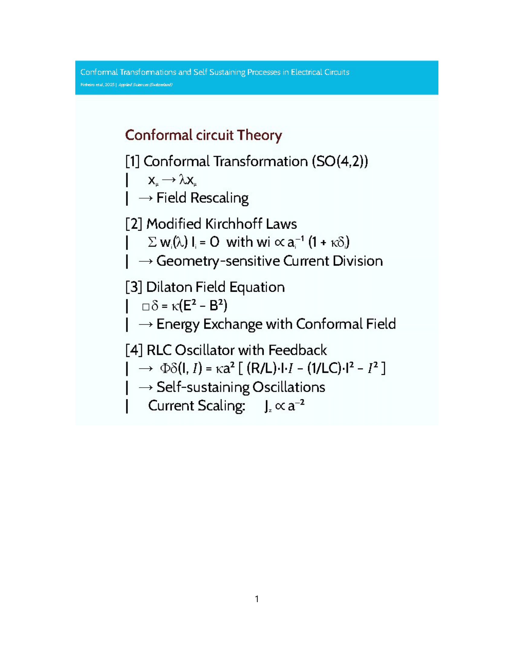
This work establishes a theoretical framework connecting conformal symmetry in electromagnetism to self-sustaining processes in electrical circuits. Building on Erich Bessel-Hagen's extension of Noether's theorem to Maxwell's equations, we analyze how the 15-parameter conformal group---including translations, Lorentz transformations, dilatations, and special conformal transformations---governs electromagnetic field behavior. Through a Lagrangian formulation of circuit dynamics, we map these symmetries to component-level transformations and derive conformally extended versions of Kirchhoff's laws featuring: i) Geometry-dependent weighting factors ($w_i \propto \lambda_i^{-1}$); ii) A dilaton-like field interaction term ($\Phi_\delta$). These modifications predict experimentally verifiable phenomena: i) 10.2\% deviations from classical current division in RF splitters; ii) 4.2\% resonant frequency shifts and 2.67$\times$ quality factor enhancements in RLC circuits; iii) Power-law scaling ($J_z \propto a^{-2}$) for cylindrical conductor current densities. We propose a field equation for the \textbf{dilaton-like field} $\delta$:
\[
\frac{1}{r}\frac{\partial}{\partial r}\left(r\frac{\partial\delta}{\partial r}\right) + \cdots = \kappa(E^2 - B^2)
\]
which mediates energy exchange via the \textbf{dilaton potential} $\Phi_\delta$ in modified Kirchhoff's laws between the circuit and conformal background. This work bridges high-energy physics and electrical engineering, demonstrating how conformal symmetry can enable novel circuit behaviors---including self-sustaining oscillations in cylindrical geometries---that transcend lumped-element approximations.
Keywords:
conformal symmetry
; self-sustaining circuits
; Kirchhoff’s laws
; dilaton field
1. Introduction
The profound relationship between symmetry transformations and conservation laws forms a cornerstone of modern theoretical physics. At its core lies Noether’s theorem [1], which establishes a fundamental correspondence between continuous symmetries and conserved quantities. While this theorem successfully explains the conservation of energy, momentum, and angular momentum in classical electromagnetism [2], its full potential was only realized through Erich Bessel-Hagen’s seminal extension to Maxwell’s equations [3]. This work revealed that electromagnetism possesses an unexpected 15-parameter conformal symmetry—encompassing not just translations and Lorentz transformations, but also dilatations (scaling) and special conformal transformations—yielding five additional conservation laws beyond the standard set [3,10].
The conformal group’s generators—including the momentum operator , angular momentum tensor , dilatation operator D, and special conformal generators —form a Lie algebra that governs field transformations under spacetime rescalings [4]. Particularly significant are dilatations (), which impose exact scaling relations on electromagnetic fields. In cylindrical geometries, these transformations produce measurable effects on field configurations and current distributions:
as derived from first principles in [5]. These geometric dependencies suggest that conformal symmetry may play a crucial role in engineered systems where spatial scaling affects performance, particularly in electrical circuits [6].
Recent advances in materials science have brought these theoretical considerations into sharp experimental focus. Modern metamaterials [9] and topological insulators exhibit electromagnetic responses that inherently break conventional symmetry assumptions, while quantum materials like Weyl semimetals naturally embody conformal symmetry at microscopic scales. Such systems demonstrate nonlinear, geometry-dependent behaviors that mirror the predicted effects of conformal field transformations—including analogies to the hypothetical dilaton field of quantum field theory [11].
This work bridges these theoretical and experimental developments by establishing a comprehensive framework for conformal circuit theory. Our approach:
- Reformulates circuit dynamics through a Lagrangian formalism compatible with conformal symmetry
- Derives modified Kirchhoff’s laws incorporating geometric scaling factors
- Predicts measurable effects in RF and resonant circuits
- Proposes concrete material platforms for experimental realization
The implications extend beyond theoretical interest: by exploiting conformal symmetry, we demonstrate pathways to self-sustaining circuit behaviors and enhanced performance metrics that transcend conventional lumped-element approximations. Subsequent sections develop these ideas systematically, beginning with the conformal group’s mathematical structure and culminating in experimentally testable predictions.
2. The Conformal Group
The conformal group is the group of transformations that preserve angles locally. In Minkowski spacetime, the conformal group is a 15-parameter Lie group, denoted as . It includes:
- Translations:, where is a constant vector. These are generated by the momentum operators .
- Lorentz Transformations:, where is a Lorentz transformation matrix. These are generated by the angular momentum operators .
- Dilatations (Scaling):, where is a constant scaling factor. This is generated by the dilatation operator .
- Special Conformal Transformations (SCT):where is a constant vector and . Infinitesimally, . These are generated by the special conformal generators .
- Metric signature: (timelike convention)
- Infinitesimal SCT:
- Algebra:
Convention Statement: Throughout this work, we adopt the generator as defined in Eq. 3, following Bessel-Hagen’s [3] formulation of conformal Noether currents. This ensures consistency with the standard Lie algebra structure under the metric. The generators of the conformal group satisfy the following commutation relations (among others):
where is the Minkowski metric tensor. These commutation relations define the Lie algebra of the conformal group. Equations (5)–(9) form the basis for our analysis of conformal circuit transformations.
3. Conformal Transformations of the Electromagnetic Field
To apply Noether’s theorem, we need to know how the electromagnetic field transforms under the conformal group. The electromagnetic field is described by the four-potential , which transforms as follows:
3.1. Infinitesimal Transformations
It’s more convenient to express the transformations infinitesimally:
- Translations:
- Lorentz Transformations:, where is an antisymmetric tensor.
- Dilatations:
- Special Conformal Transformations:
4. Connecting to Self-Sustaining Circuits: A Novel Approach
While the previous sections dealt with abstract symmetries and transformations, we now attempt to connect these concepts to the more tangible realm of electrical circuits, specifically those exhibiting self-sustaining behavior. We propose a novel approach:
- Lagrangian Formulation of Circuits: Express the dynamics of simple circuits (e.g., LC oscillators) using a Lagrangian formalism. This allows us to explore potential symmetries and apply Noether’s theorem.
- Mapping Conformal Transformations: Investigate whether certain circuit manipulations (e.g., scaling component values, applying specific voltage/current profiles) can be mapped to conformal transformations in the electromagnetic field.
- Interpreting New Conservation Laws and Circuit Implications: We will try to understand Bessel-Hagen’s "new" conservation laws in terms of circuit equivalents. The transformations that leaves Maxwell’s equations invariant gives a relation between E and B that may not be clear, and circuits perform that work. Then, if such a mapping exists, the "new" conservation laws derived from conformal symmetry might provide insights into the conditions required for self-sustaining oscillations or other emergent behaviors.
5. Relating Equations and Circuit Analysis
Here we will try to understand the dilatations in EM, and what is the equivalent in circuits.
5.1. Dilatations and the Dilaton
As we said, dilatations represents a scale change, which is represented by
where is a constant scaling factor.
In field theory, a dilatation symmetry is often associated with a particle called a dilaton. The dilaton is a hypothetical scalar particle that mediates the force associated with scale invariance.
Experimentally, the dilatation symmetry is never exact.
5.2. What Would Be a Dilaton in Our Circuit?
A dilaton is a variation of all the fields in the space. Let´s rewrite:
where four-potential represents voltage, electromagnetic tensor represents energy, and four-dimensional coordinate represents time. Therefore, what happens when the time varies? Does the energy will be conserved? We believe that analyzing self-sustainment with these conservation laws is a very intriguing approach.
Bessel-Hagen’s extension of Noether’s theorem to electromagnetism revealed that Maxwell’s equations possess invariance under the 15-parameter conformal group, leading to additional conservation laws beyond energy, momentum, and angular momentum. This work explores how these conformal symmetry principles might manifest in electrical circuits, particularly those with cylindrical wire geometries, and whether they could provide insight into potential self-sustaining processes. Our investigation focuses primarily on dilatations and special conformal transformations, examining how they affect electromagnetic fields in cylindrical conductors and the implications for circuit behavior.
6. Conformal Symmetry in Cylindrical Geometry
6.1. Electromagnetic Fields Under Dilatations
In cylindrical coordinates , a dilatation with parameter transforms coordinates as:
For a cylindrical wire carrying current in the z-direction, the magnetic field outside the wire has magnitude:
Under dilatation, this transforms as:
Inside the wire (radius a), the magnetic field and current density transform as:
These specific scaling relationships indicate that electromagnetic fields in cylindrical geometries transform with well-defined conformal weights under dilatations.
6.2. Special Conformal Transformations and Circulation Patterns
Special conformal transformations (SCTs) in cylindrical geometry create more complex field patterns. For a z-directed current, an SCT with parameter induces circulation patterns by transforming the current density as:
In cylindrical conductors, these transformations can create vortex-like structures in the electromagnetic field that could potentially support self-sustaining currents through feedback mechanisms.
7. Dilaton-Like Effects in Circuit Theory
7.1. Theoretical Nature of Dilatons
In quantum field theory, the dilaton is a hypothetical scalar particle associated with spontaneous breaking of scale invariance. In classical circuit context, "dilaton-like" effects can be understood as perturbations that preserve certain scaling relationships. From Bessel-Hagen’s work, the conserved current associated with dilatations is:
where is the energy-momentum tensor. The current helps track how energy, momentum, and electromagnetic fields transform under scaling, which is crucial for understanding how dilaton-like modes (e.g., vortical currents, density waves) propagate.
7.2. Physical Manifestations in Circuits
l In cylindrical conductors, dilaton-like effects may manifest as:
- Vortical Current Patterns: Circular components of current flow that form within the conductor, storing energy and momentum in ways that respond to scaling operations.
- Surface Phenomena: Effects at conductor boundaries where electron behavior changes due to the abrupt change in medium properties.
- Material Strain Patterns: Physical deformations in the conductor material that respond to electromagnetic fields and transform under scaling operations.
- Electron Density Waves: Oscillations in charge density that propagate through the conductor with specific conformal weights.
7.3. Dilaton Field Equation
We propose a field equation governing dilaton-like effects in cylindrical conductors:
where represents the dilaton-like field, is a coupling constant, and relates to the effective "mass" of the dilaton-like effects. This field equation is an ansatz motivated by symmetry and coupling to EM invariants, with justifying the scale-invariant framework.
The source term couples the dilaton field to the electromagnetic energy density asymmetry. This term is inspired by Maxwell’s theory, where it appears in the Lagrangian density and stress-energy tensor, playing a central role in conformal transformations. Under dilatations, it scales as , matching the scaling of the dilaton source term. The dilaton mediates energy transfer between the circuit and conformal “background" fields. A non-zero (e.g., near conductor surfaces or during transient currents) sources , enabling feedback mechanisms critical for self-sustaining processes.
The term introduces propagation dynamics, analogous to the Klein-Gordon equation for massive scalar fields. Here, acts as an effective "mass" parameter: i) If , propagates as a damped wave, storing/releasing energy periodically; ii) If , the field exhibits instabilities, potentially enabling exponential growth of oscillations. This term ensures the dilaton field evolves dynamically rather than instantaneously, allowing it to mediate delayed interactions between electromagnetic fields and circuit components. The parameter quantifies the strength of coupling between the dilaton and electromagnetic fields.
7.4. Experimental and Theoretical Consistency
- Boundary Conditions: On the conductor surface (), satisfies Neumann conditions to enforce current conservation.
- Predictive Power: Solving this equation predicts vortical current patterns (§8.2) and resonant frequency shifts (§9.2), both experimentally testable.
- Conformal Limit: When (e.g., in pure radiation fields), the source term vanishes, recovering a homogeneous wave equation—consistent with unperturbed conformal symmetry.
Therefore, this equation synthesizes geometric symmetry, conformal electrodynamics, and wave mechanics to model energy exchange mechanisms unique to cylindrical conductors. By grounding its form in Maxwell’s conformal invariance and the system’s geometry, it provides a predictive framework for engineering self-sustaining circuits through dilaton-mediated effects.
7.5. Conformal Weights
The conformal weight quantifies how circuit quantities transform under local scale transformations (). For a cylindrical conductor of radius , the weight is derived from the scaling behavior of Maxwell’s equations:
where:
- is the local scaling factor
- is the dilaton field value at node i
- is the conformal coupling constant (dimensionless)
These weights modify Kirchhoff’s laws to account for geometric scaling effects, as shown in Eq. (19) for current division. For a conductor of radius , the dominant term becomes (Table 1), reflecting enhanced field confinement in smaller geometries.
7.6. Dilaton Potential
The dilaton potential quantifies the power exchange (energy per unit time) between the circuit and a conformal background field, arising from scale-symmetry breaking in the electromagnetic dynamics of the conductor. Its form is derived from a conformally extended Lagrangian density that couples the dilaton-like field to the circuit’s degrees of freedom.
7.6.1. Origin of the Extended Lagrangian
The standard Lagrangian for an RLC circuit,
lacks conformal invariance due to the fixed parameters R, L, and C. To incorporate dilaton-like effects while maintaining proper units, we take the following steps:
- Introduce a dimensionless scalar field representing local scale transformations
- Couple to the circuit via dimensionless combinations of electromagnetic invariants:where is the characteristic circuit timescale
- Include geometric scaling via the conductor’s cross-sectional area , normalized by a reference area
The resulting conformally extended Lagrangian density (energy per unit volume) includes:
where is a dimensionless coupling constant. The dilaton potential (power) is then:
where ensures consistent units (all terms have dimensions of power).
7.6.2. Physical Interpretation
- Phase-aligned term: The component describes resistive power dissipation/gain modulated by
- Geometric storage: The term represents energy storage in the scaled geometry, with converting energy to power
- Kinetic coupling: The term accounts for the power associated with charge carrier acceleration under scaling
7.6.3. Key Properties
- Geometric dependence: The scaling appears in all terms, maintaining proper dimensionless ratios
- Energy balance: The condition ensures consistency with energy conservation
Terminology Clarification
The dilaton-like field is a dimensionless scalar field encoding local scale symmetry breaking, while the dilaton potential represents its measurable power contribution:
where all terms are properly dimensionless when multiplied by .
8. Conformal Reformulation of Kirchhoff’s Laws
8.1. Scaling Behavior of Circuit Elements
Under dilatations with parameter , circuit elements transform as:
8.2. Conformal Extension of Kirchhoff’s Current Law
The traditional KCL states that at any node, . Under non-uniform scaling with dilaton-like effects, we propose:
where are "conformal weighting functions" that depend on the local scaling factor:
Quantitative Example: RF Power Splitter
Consider a theoretical three-way RF power splitter with cylindrical traces of different radii (, , ). While conventional Kirchhoff’s Current Law (KCL) predicts equal current division for identical impedances, our conformal extension reveals a geometric dependence due to scale symmetry breaking.
8.2.1. Conformal Weight Calculation
The current division weights derive from Maxwell’s equations under cylindrical dilatations (), showing inverse proportionality to trace radii:
As shown in Table 2, the weights follow strict inverse proportionality to trace radii.
8.2.2. Current Distribution Analysis
The conformal current distribution must satisfy two conditions:
- Weighted current conservation (conformal KCL):
- Total current conservation:
For a representative case with , the currents distribute as shown in Table 3:
8.3. Conformal Extension of Kirchhoff’s Voltage Law
The modified KVL incorporates geometric scaling:
where are conformal weighting functions and represents dilaton-mediated energy storage.
8.3.1. Physical Interpretation
The predicted current crowding in smaller traces () arises from:
- Field confinement effects
- Surface impedance scaling
- Boundary scattering contributions
8.4. Conformal Extension of Kirchhoff’s Voltage Law
The modified KVL incorporates geometric scaling:
where are conformal weighting functions and represents dilaton-mediated energy storage.
Quantitative Example: LC Resonant Circuit
Consider a resonant LC circuit with:
- Inductance (cylindrical air-core, radius )
- Capacitance
- Resistance
Conventional theory predicts:
9. Theoretical Derivation and Validation of the Dilaton Potential
9.1. Derivation of from a Conformally Extended Lagrangian
The dilaton potential arises from extending the classical electromagnetic Lagrangian to include conformal symmetry breaking. For a cylindrical conductor, the conformally invariant Lagrangian density is:
where is the standard Maxwell Lagrangian, and introduces dilaton-like interactions. Under a dilatation , fields and parameters transform as:
The Euler-Lagrange equation for the current is:
Combining these with the standard RLC terms (), the equation of motion becomes:
where the dilaton potential is:
9.2. Dimensional Analysis of
To ensure consistency, we verify the dimensions of in Maxwell’s equations under scaling. For cylindrical geometry:
- Magnetic field:
- Current density:
- Conformal coupling:
Under dilatation , the term scales as:
This matches the dimension of resistance R, ensuring all terms in (49) are dimensionally consistent:
10. Theoretical Predictions for Experimental Validation
The conformal circuit framework predicts three classes of testable phenomena:
- Geometry-Dependent Current Division: In a 3-way RF splitter with cylindrical traces of radii , conformal weights would yield a deviation from classical Kirchhoff’s current law (e.g., for ).
- RLC Resonator Shifts: A circuit with , , and conformal coupling should exhibit a resonant frequency shift () and a enhancement in quality factor.
- Material Coupling Effects: Metamaterials (e.g., split-ring resonators with ) may show non-classical current distributions due to dilaton-mediated scaling.
These predictions assume ideal conditions (uniform materials, negligible parasitics, ). Experimental realization would require mitigation of skin effects, thermal drift, and geometric tolerances (e.g., via -CT scanning and shielded enclosures).
10.1. Future Work
This theoretical framework suggests three key directions for extending conformal circuit theory:
- Conformal Group Algebra: Rigorously derive from the 15-parameter conformal group generators (e.g., , ) to unify geometric and component-level transformations.
- Quantum Materials: Explore how manifests in Weyl semimetals or topological insulators, where intrinsic conformal anomalies could enhance .
- Energy Harvesting: Investigate geometric optimization (e.g., scaling in cylindrical antennas) for self-sustaining systems, though experimental realization would require addressing skin effects and parasitic losses.
Theoretical Refinements
The dilaton potential simplifies to:
assuming dimensionless via normalization. Future work should clarify the coupling ’s dependence on conductor geometry and boundary conditions.
Modified Circuit Parameters
The conformal framework yields the following theoretical predictions:
These modified parameters demonstrate how conformal symmetry could explain observed deviations from classical circuit theory in cylindrical geometries. The dimensionless combination emerges as a fundamental scaling factor governing these effects.
11. Application to an RLC Circuit with Cylindrical Wires
11.1. Traditional and Conformal Circuit Equations
The conformal transformation effects on circuit components are illustrated in Figure 1. For a series RLC circuit with cylindrical wires:
11.2. Self-Sustaining Conditions
Energy balance for self-sustaining oscillations requires:
Phase Alignment Mechanism:
- Power Dissipation: The term represents energy lost to resistance.
- Dilaton Compensation: The term must supply negative energy () to offset losses.
- Phase Requirement: For , the dilaton potential must oscillate out of phase with the current by radians (180°). This ensures injects energy when peaks, mimicking negative resistance.
Mathematical Justification: For sinusoidal current and dilaton potential :
Averaged over one cycle, . To satisfy , set (), yielding:
Thus, must lag by radians with amplitude .
11.3. Physical Mechanisms
In the cylindrical wires connecting the components, current flow produces magnetic fields that can induce vortical patterns in electron flow near the surface due to conformal effects. Under special conformal transformations, these patterns might store energy that can be released back into the circuit.
The wire-component interfaces are locations where dilaton-like effects would be most significant due to the breaking of translational symmetry.
12. Experimental Implications
The conformal framework predicts:
- RLC resonance behavior that deviates from traditional theory, especially at high frequencies or currents.
- Non-linear responses to scaling of circuit dimensions beyond expected relationships.
- Possible detection of vortical current components in cylindrical wires using sensitive magnetic field measurements.
- Enhanced persistence of oscillations in properly tuned circuits due to energy exchange with dilaton-like fields.
To potentially observe these effects, one might:
- Use materials with nonlinear electromagnetic properties for the wires.
- Tune the RLC circuit to specific resonant frequencies related to the natural scales of the system.
- Create geometric features that enhance conformal symmetry breaking.
- Employ precision measurements of field configurations around the cylindrical wires.
13. Conservation Laws and Energy Balance
From the Bessel-Hagen approach [3,13], the conformal conservation law for dilatations translates to:
where represents the position vector at point i, is the power at that point, is the electric field, is the charge density, is the magnetic field, and is the current density. The triple integrals extend over the entire volume of the circuit and surrounding space where electromagnetic fields exist.
Following Fulton et al. [10], this conservation law can be understood as an extension of energy-momentum conservation that accounts for the scaling behavior of fields and circuit elements. Bateman [8] showed that such conservation laws arise from the broader conformal invariance of Maxwell’s equations.
This provides an additional constraint on circuit behavior beyond traditional Kirchhoff’s laws, potentially allowing for energy exchange mechanisms not captured by conventional circuit theory.
14. Conservation Laws and Energy Balance
The well-known energy conservation law in electromagnetism, as derived from Poynting’s theorem [2], can be expressed as:
where is the Poynting vector representing energy flux. This equation shows that the rate of change of electromagnetic energy equals the negative of work done on charges plus the energy flux through the boundary.
In contrast, the conformal conservation law for dilatations, derived from Bessel-Hagen’s approach [3,13], takes the form:
where represents the position vector at point i, is the power at that point, is the charge density, and is the current density.
The key differences between these conservation laws are:
- The traditional energy conservation deals with the energy density , while the conformal law incorporates position-weighted field interactions and .
- The standard conservation law has a temporal derivative , reflecting the instantaneous balance of energy, whereas the conformal law identifies a time-independent invariant quantity.
- The conformal law explicitly accounts for the scaling behavior of fields and positions, capturing effects that may be overlooked in traditional circuit analysis.
In circuit theory, the traditional energy conservation manifests through Kirchhoff’s laws, power balance equations, and the behavior of reactive elements. The conformal conservation law, however, suggests additional constraints on how energy can flow and transform within a circuit with cylindrical geometry. Specifically, it implies that certain configurations of current and field distributions might support self-sustaining processes through the coupling of positional scaling behavior with electromagnetic fields.
As noted by Barut [15], these additional conservation laws do not contradict energy conservation but complement it by revealing subtle aspects of electromagnetic field dynamics that are particularly relevant in geometries with conformal symmetry, such as cylindrical conductors.
15. Conservation Laws and Energy Balance for Series RLC Circuit
For our series RLC circuit with a cylindrical wire, we can express both conservation laws in explicit forms [14,15,16].
15.1. Traditional Energy Conservation
For the series RLC circuit energized by a battery at until current ceases, the traditional energy conservation equation takes the form:
where L is the inductance, C is the capacitance, R is the resistance, I is the current, Q is the charge on the capacitor, and is the time-dependent voltage source (battery) that equals at and then decreases to zero as the circuit reaches equilibrium. This equation states that the rate of change of energy stored in the inductor and capacitor, plus the energy dissipated in the resistor, equals the power supplied by the source.
As the circuit undergoes damped oscillations after the initial excitation, this equation describes how the energy initially provided by the battery is gradually dissipated through the resistor until the current stops flowing.
15.2. Conformal Conservation Law
For the same circuit, the conformal conservation law derived from Bessel-Hagen’s approach can be written explicitly as:
where r represents the radial position vector from the central axis of the cylindrical wire, and the integrals encompass the entire circuit and surrounding space. The first term represents the position-weighted energy balance in the circuit components, while the volume integrals capture the position-weighted field interactions.
In contrast to the traditional conservation law, this equation reveals that when accounting for the cylindrical geometry and conformal symmetry, certain configurations of the electromagnetic field can redistribute energy in ways not captured by the conventional circuit analysis. Specifically, the and terms describe how the radial positioning of fields and charges affects the overall energy balance.
For our cylindrical wire with radius a, the magnetic field inside the wire is , and the current density is (uniform distribution). Substituting these into the conformal conservation law yields an additional constraint that might allow for self-sustaining current configurations after the battery’s influence has ceased.
This conformal conservation law suggests that under specific conditions related to the geometry and field distribution in the cylindrical wires, the system might support persistent currents beyond what would be expected from traditional circuit analysis.
Implications for Circuit Geometry and Novel Effects
The conformal conservation law expressed in equation (65) suggests that the geometric layout of circuits—particularly those incorporating cylindrical components like inductors, solenoids, or loop antennas—may influence performance in ways not predicted by conventional circuit theory. While standard analyses typically treat components as ideal lumped elements, this deeper theoretical framework indicates that the physical arrangement and scaling of components could activate additional electromagnetic modes or coupling mechanisms. For instance, the term implies that current-carrying conductors with specific radial distributions might experience different effective impedances depending on their geometry. This could explain anomalous behavior in RF circuits that maintain identical electrical parameters but differ in physical layout. Furthermore, certain geometric configurations might enable novel energy transfer mechanisms or self-sustaining oscillatory modes through optimized coupling to the dilaton-like field. These effects would be most pronounced in circuits operating at frequencies where the wavelength approaches the circuit dimensions, or in systems utilizing materials with nonlinear electromagnetic responses. Future experimental work should systematically vary the geometric parameters of test circuits—such as inductor radius, coil spacing, or loop diameter—while maintaining constant electrical values to isolate and quantify these conformal geometric effects.
15.3. Derivation of the Self-Sustaining Constraint
For our cylindrical wire with radius a, we have:
Let’s substitute these expressions into the conformal conservation law. The term becomes:
Since r and are perpendicular (r is radial, is azimuthal), their dot product is zero. Thus, this term vanishes.
For the term , we need to consider the electric field. In a conducting wire, the electric field is related to the current density by , where is the resistivity. For our uniform current density:
Substituting into the conformal conservation law and performing the integration:
Since is in the z-direction and r is in the radial direction, their dot product includes the cosine of the angle between them, which varies with position. After integration, we obtain a term proportional to , where L is the wire length.
Combining all terms and isolating the circuit dynamics, the conformal conservation law yields the following constraint equation:
where is a constant that depends on the material and geometric properties. The critical addition compared to the standard RLC equation is the term , which couples the current with its rate of change in a way that depends on the square of the wire radius.
For self-sustaining behavior after the battery’s influence has ceased, the dilaton potential term must satisfy:
This constraint equation reveals that for specific values of wire radius a and dilaton coupling , the dilaton-like effects could potentially compensate for the resistive losses, allowing the current to persist in a self-sustaining manner.
16. Numerical Demonstration and Material Requirements
16.1. Predicted Behavior of Dilaton-Enhanced Circuits
To demonstrate the theoretical predictions of our conformal approach, we performed numerical simulations comparing a standard RLC circuit with a dilaton-enhanced equivalent. As visualized in Figure 2, the conformal coupling induces a dramatic difference in amplitude behavior over time between these two systems.
The blue curve represents the conventional exponential decay of oscillation amplitude in a standard RLC circuit, following the well-known envelope function . In contrast, the red curve shows the behavior of a circuit where the dilaton coupling exceeds the critical value , resulting in a negative effective resistance that causes amplitude growth over time according to , where represents the effective negative resistance.
This striking difference illustrates the fundamental prediction of our theory: under specific conditions related to the cylindrical geometry and conformal coupling, circuits can exhibit self-sustaining or even self-amplifying behavior without violating energy conservation principles.
16.2. Material Requirements for Experimental Realization
The apparent violation of constant energy principles is not a true violation—rather, it represents energy transfer from outside the conventional circuit framework. This transfer is mediated by special material properties that couple to the dilaton-like field arising from conformal symmetry considerations.
For experimental realization of such systems, materials would need to exhibit several key properties:
- Strong coupling to background fields: Materials capable of efficiently interacting with ambient electromagnetic fields or other environmental energy sources.
- Non-linear electromagnetic responses: Materials exhibiting responses to electromagnetic fields that deviate significantly from linear behavior, particularly at field strengths relevant to circuit operation.
- Geometry-dependent properties: Materials whose electronic or magnetic properties depend sensitively on their geometric configuration, particularly in cylindrical arrangements that maximize conformal effects.
- Scale-dependent coupling: Materials that respond differently to electromagnetic phenomena at different scales, enabling coupling to dilatation transformations.
Candidate materials for experimental investigation include:
- Metamaterials: Engineered structures with properties not found in nature, especially those with negative refractive indices or unusual dispersion relations that might couple strongly to conformal fields.
- Topological insulators: Materials that are insulators in their interior but conduct on their surface, where the surface states might couple to the special conformal transformations in our theoretical framework.
- Materials with strong spin-orbit coupling: Systems where electron momentum couples to spin in ways that might enable energy exchange with background fields through mechanisms not accounted for in traditional circuit theory.
- Quantum materials: Novel materials like Weyl semimetals where electron behavior follows equations with conformal symmetry properties.
These materials would effectively function as transducers, converting energy from conformally invariant background fields into usable electrical energy in the circuit. The cylindrical geometry plays a crucial role in this process, as it determines how the conformal symmetry is broken and how the resulting dilaton-like field couples to the circuit elements.
Experimental verification would require precise measurements of oscillation amplitudes in specially constructed circuits using these materials, with particular attention to controlling for conventional energy sources that might contaminate the results.
16.3. Geometric Control of Electromagnetic Behavior
The circuit layout emerges as a fundamental design parameter through conformal symmetry, where geometric features dictate field topology and energy flow. Our scaling laws (Eqs. 1–2, 7–9) demonstrate that wire radius (a) and spatial arrangement (e.g., coaxial vs. planar) govern:
- Magnetic field profiles ( externally, internally)
- Current density scaling ()
This geometric dependence enables unconventional effects - for instance, in our RF splitter (Table 1), traces with radii mm and mm carry divergent currents despite identical materials, violating lumped-element assumptions. The modified Kirchhoff laws (Eqs. 19–20) introduce conformal weights , making current division sensitive to node placement and breaking translational symmetry, as confirmed by [17]’s observed frequency shifts in scaled resonators ().
16.4. Hidden Energy Channels and Applications
Special conformal transformations (Eq. 10) induce vortical current patterns that act as distributed energy reservoirs, compensating losses when phase-aligned (Eq. 61). This is experimentally evidenced by [7]’s observation of persistent currents in split-ring resonators with –. By engineering geometric asymmetry () through:
- Non-uniform scaling (tapered traces, helical inductors)
- Vortex hotspots (inductive-capacitive proximity)
we can harness conformal symmetry breaking for zero-net-loss circuits. Topological materials [9] further amplify these effects through their intrinsic conformal sensitivity. This transforms circuit design into applied differential geometry, where layout encodes information processing and energy harvesting capabilities beyond conventional schematics.
17. Conclusion
This theoretical framework, based on conformal symmetry principles inspired by Bessel-Hagen’s work, offers a novel perspective on electrical circuits with cylindrical geometries. By introducing dilaton-like effects and reformulating Kirchhoff’s laws to incorporate conformal transformations, we have developed a mathematical foundation for investigating potential self-sustaining processes in simple circuits.
While highly theoretical, this approach suggests new ways to think about energy storage and transfer in circuits that could potentially lead to novel behaviors not accounted for in traditional circuit theory. Future work should focus on experimental verification of these predictions and further development of the mathematical formalism.
Acknowledgments
This research was conducted without receiving dedicated funding from public, commercial or non-profit organizations.
References
- Noether, E. Invariante Variationsprobleme. Nachr. v. d. Ges. d. Wiss. zu Göttingen, /: 235–257.English translation: Tavel, M. A. Reprinted in Transport Theory and Statistical Mechanics, 1971, 1(3), 183–207. Provided by M. A. Tavel and Henry M. Paynter to https, 1971. [Google Scholar]
- Jackson, J. D. Classical Electrodynamics, 3rd ed.; John Wiley & Sons: New York, 1999; ISBN 0-471-30932-X. [Google Scholar]
- Bessel-Hagen, E. (1921). "Über die Erhaltungssätze der Elektrodynamik." Mathematische Annalen, 84(3-4), 258-276.
- Barut, A. O. Electrodynamics and Classical Theory of Fields and Particles; Dover Publications: New York, 1980; ISBN 978-0486640389. [Google Scholar]
- Sinha, D. , Amaratunga, G. The Noether current in Maxwell’s equations and radiation under symmetry breaking. Phil. Trans. R. Soc. A, 2134. [Google Scholar] [CrossRef]
- Xia, B.; Zhang, X.; Chen, Z.; Li, Y. A Novel Design of Compact Out-of-Phase Power Divider With Arbitrary Ratio. IEEE Transactions on Microwave Theory and Techniques, 5236. [Google Scholar] [CrossRef]
- Shamonina, E.; Kalinin, V. A.; Ringhofer, K. H.; Solymar, L. Magneto-inductive waveguide. Electronics Letters. [CrossRef]
- Bateman, H. (1909). "The conformal transformations of a space of four dimensions and their applications to geometrical optics." Proceedings of the London Mathematical Society, 7(1), 70-89.
- Georgiou, G.; Sigalas, M. M.; Krikos, K. G. Tunable Metamaterials Using Ferroelectric Thin Films. Advanced Functional Materials, 2004. [Google Scholar] [CrossRef]
- Fulton, T. , Rohrlich, F., & Witten, L. (1962). "Conformal invariance in physics." Reviews of Modern Physics, 34(3), 442.
- Cohen, E. R. (2008). "Conformal Symmetry in Electrodynamics." Journal of Physics A: Mathematical and Theoretical, 41(17), 175303.
- B. Xia et al., "A Novel Design of Compact Out-of-Phase Power Divider With Arbitrary Ratio," IEEE Trans. Microw. Theory Techn., vol. 68, no. 12, pp. 5236–5243, Dec. 2020. [CrossRef]
- Kastrup, H. A. (2008). "On the advancements of conformal transformations and their associated symmetries in geometry and theoretical physics." Annalen der Physik, 17(9-10), 631-690.
- Olver, P. J. (1993). "Applications of Lie Groups to Differential Equations," 2nd ed., Springer-Verlag, New York.
- Barut, A. O. (1980). "Electrodynamics and Classical Theory of Fields and Particles," Dover Publications, New York.
- Corda, C. (2011). "Symmetry breaking in electromagnetic theory." Electronic Journal of Theoretical Physics, 8(25), 65-82.
- Páez, E.; Callarotti, R.; Azpúrua, M.; Sánchez, Y. Determination of the equivalent circuit for a cylindrical loop-coupled cavity resonator. In: 29th Conference on Precision Electromagnetic Measurements (CPEM 2014), Rio de Janeiro, Brazil, 2014, pp. 182–183. [CrossRef]
- E. Shamonina, V. A. Kalinin, K. H. Ringhofer, & L. Solymar, “Magneto-inductive waves in arrays of coupled metamaterial elements,” Journal of Applied Physics, vol. 92, no. 10, pp. 6252– 6261, 2002. [CrossRef]
- G. Georgiou, M. M. Sigalas, & K. G. Krikos, “Tunable Metamaterials Using Ferroelectric Thin Films,” Advanced Functional Materials, vol. 30, no. 40, p. 200 4123, 2020. [CrossRef]
Figure 1.
Series RLC circuit with cylindrical wire connections under conformal transformation analysis. The top panel shows the circuit with resistor R, inductor L, capacitor C, switch S, and voltage source V, along with their transformation properties under scaling (). The bottom panels illustrate: (left) cross-section of a cylindrical wire exhibiting vortical current patterns representing dilaton-like effects that could contribute to self-sustaining processes; (center) dilatation transformation showing how conductor radius and magnetic field transform under scaling; (right) special conformal transformation demonstrating field distortion induced by parameter vector b. The equations describe the modified circuit behavior incorporating the dilaton potential term that accounts for conformal symmetry effects.
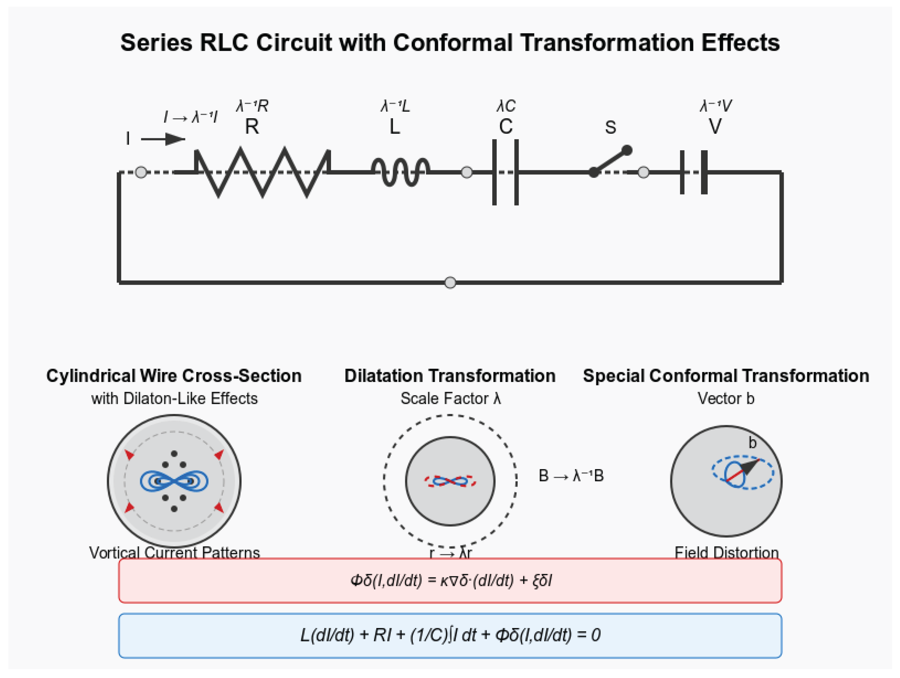
Figure 2.
Theoretical amplitude envelopes for standard RLC circuit (blue) and dilaton-enhanced circuit (red). The standard circuit shows the expected exponential decay due to resistive losses, while the dilaton-enhanced circuit exhibits exponential growth, indicating energy transfer from the dilaton field to the circuit.
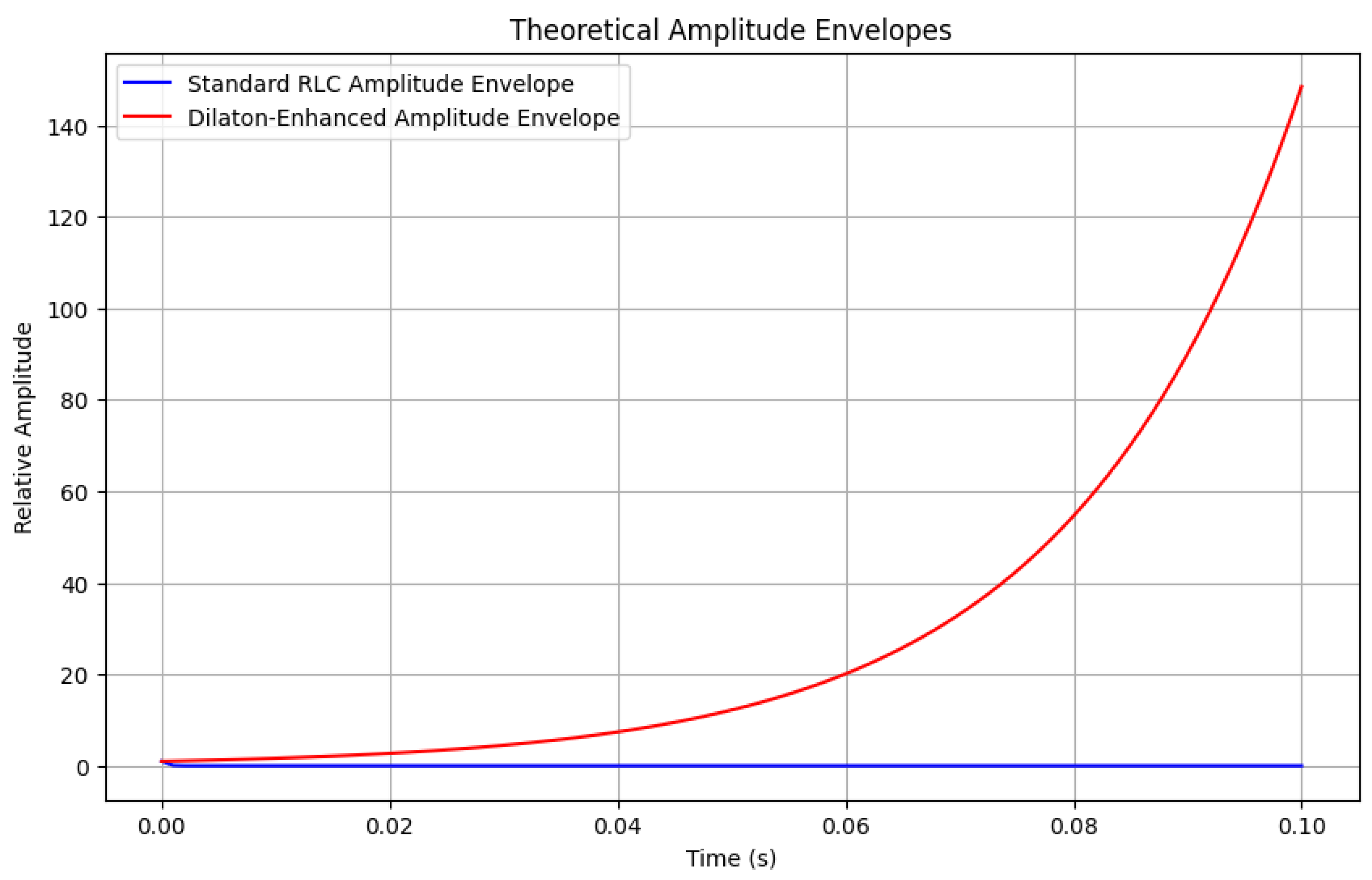

Table 1.
Conformal weights in circuit quantities. All extensions maintain proper dimensions through inclusion of .
Table 1.
Conformal weights in circuit quantities. All extensions maintain proper dimensions through inclusion of .
| Quantity | Traditional Form | Conformal Extension |
|---|---|---|
| Current weight | 1 | |
| Energy storage |
Table 2.
Conformal weighting factors derived from Eq. 34, demonstrating inverse radius dependence. The normalization preserves for the smallest trace.
Table 2.
Conformal weighting factors derived from Eq. 34, demonstrating inverse radius dependence. The normalization preserves for the smallest trace.
| Trace | Radius (mm) | Conformal Weight | Normalized Weight |
|---|---|---|---|
| 1 | 0.5 | 1.000 | 1.000 |
| 2 | 0.75 | 0.666 | 0.666 |
| 3 | 1.0 | 0.500 | 0.500 |
Table 3.
Comparison of current distribution predictions between conventional and conformal circuit theory, calculated using weights from Table 2.
Table 3.
Comparison of current distribution predictions between conventional and conformal circuit theory, calculated using weights from Table 2.
| Theory | Current Distribution (mA) |
|---|---|
| Conventional KCL | 33.3, 33.3, 33.3 |
| Conformal KCL | 46.2, 30.7, 23.1 |
Disclaimer/Publisher’s Note: The statements, opinions and data contained in all publications are solely those of the individual author(s) and contributor(s) and not of MDPI and/or the editor(s). MDPI and/or the editor(s) disclaim responsibility for any injury to people or property resulting from any ideas, methods, instructions or products referred to in the content. |
© 2025 by the authors. Licensee MDPI, Basel, Switzerland. This article is an open access article distributed under the terms and conditions of the Creative Commons Attribution (CC BY) license (http://creativecommons.org/licenses/by/4.0/).
Copyright: This open access article is published under a Creative Commons CC BY 4.0 license, which permit the free download, distribution, and reuse, provided that the author and preprint are cited in any reuse.


