
Submitted:
14 July 2025
Posted:
15 July 2025
You are already at the latest version
Abstract
This paper describes the results and benefits of applying a comprehensive methodology for simulating and planning surgeries related to the restoration of bone structures damaged by various types of pathologies, through seven clinical success cases. Pre-surgery simulations are performed using 3D printed anatomical test models. In addition, restorations or bone transformations are supported by customised implants manufactured for each case, including customised cutting guides as well. Appropriate polymeric materials are used, and Fused Deposition Modelling (FDM) is applied as the main additive manufacturing technique to obtain the medical devices. The results demonstrate the feasibility of applying such techniques, their advantages and the possibilities of access to them in Ecuador.
Keywords:
additive manufacturing
; cutting guide
; surgical planning
; medical image
; reverse engineering
1. Introduction
Additive manufacturing (AM) is being applied in many areas of social development. Among these, public health stands out. This technology is significantly impacting the medical sector, helping to produce customised and complex medical devices, improving the results of surgical procedures on patients and optimising their precision.
Additive manufacturing facilitates the production of customised implants, i.e. implants tailored to the individual anatomy of the patient receiving the implant. Such customisation measures have been demonstrated to ensure an adequate fit level and improve surgical outcomes [1,2,3]. Furthermore, technological advances in this field demonstrate great results in enhanced patient comfort and satisfaction [4,5]. Additionally, the fabrication of intricate structures and complex geometries, which are challenging to replicate through conventional manufacturing methodologies, is attainable [3,6].
A recent literature review indicates a substantial increase in scientific publications concerning surgical applications of AM and 3D printing. Cranio-maxillofacial surgery accounted for the second highest percentage of these publications. As additive manufacturing technology improves and becomes more affordable, its use in plastic and reconstructive surgery is also expanding (see references [7,8]).
In such applications, the materials employed encompass biocompatible metals, such as titanium alloys, polymers and bio-composites, which possess the capacity to emulate (and even surpass) the mechanical properties of bone [9,10,11]. A variety of additive manufacturing techniques are under development to produce medical devices for a range of specific applications. The following processes are included: direct laser sintering of metals, stereolithography, selective laser sintering, modelling and fused deposition manufacturing or fused deposition modelling (FDM) [11,12,13,14,15,16,17,18].
Image integration and reverse engineering processes are of pivotal significance in the medical device manufacturing domain. Additive manufacturing has been demonstrated to successfully integrate with medical imaging techniques (e.g. computed tomography (CT) scans) to create accurate three-dimensional digital models of the patient’s specific anatomy. These models are integrated into design methodologies and the additive manufacturing processes themselves, intending to digitally generate surgical instruments, anatomical test models to simulate procedures, implants and surgical guides [3,6]. Reverse engineering is defined as the process of creating a three-dimensional digital model of an object or organ of a patient’s anatomy from medical imaging data [6]. These models are indispensable for designing perfectly fitting implants, reducing the risk of implant failure and improving post-intervention outcomes. The extent of customisation ensures that devices possess optimal dimensions, form, and mechanical properties, which are particularly advantageous in complex surgeries, such as craniomaxillofacial and orthopaedic surgeries [1,19,20,21,22].
Medical images (e.g. magnetic resonance imaging (MRI), CT scan, X-ray, ultrasound) can play a key role in fabricating customised medical devices and implants through additive manufacturing technology. This process is comprised of a series of stages in which image data plays an important role. In the context of custom implants, for instance, CT and MRI are the techniques most frequently employed to obtain detailed images of the patient’s anatomy. These images are then converted into digital models that accurately represent the patient’s unique anatomical features [23,24,25]. The subsequent processing of the acquired image data is facilitated by specialised software (e.g. OsiriX Imaging Software, 3D Slicer, Mimics, Magics, 3D Doctor, InVesalius, among others), which enables the creation of a 3D digital model. This model is then exported in a standard triangulated language (or stereolithography) (STL) format for utilisation in AM technologies [1,15,19,23,24]. The implant parameters verification, including shape, external dimensions and internal structure (e.g. porosity), is also performed by imaging techniques such as CT [16,17]. In the context of manufacturing, the thickness of the layer during production is a critical factor, as it can influence the mechanical properties and the precision of the implant [26].
The necessity for enhanced visualisation of surgical processes and outcomes has precipitated the emergence of anatomical test models, patient-specific surgical guides (in addition to customised 3D printed implants) [8]. These processes involve several critical considerations to ensure accuracy, safety and efficacy. Cutting guides must be adapted to the patient’s anatomy to ensure accurate fit and effective surgical outcomes [2,27,28]. The materials utilised must demonstrate an adequate degree of biocompatibility to circumvent the occurrence of adverse reactions. An anatomical test model used for simulating surgery does not necessitate the utilisation of a biocompatible material in its fabrication. In the case of an implant intended to be permanent, it is essential to utilise a material that exhibits the highest degree of biocompatibility. The most common materials used in this process are polymers and metals, such as titanium and polyether-ether-ketone (PEEK) [13,27]. The clear procedural establishment, standards design, and guidelines are also of great importance. This includes ensuring that the cutting guide can be uniquely positioned and stably fixed during surgery [27,29].
Before clinical implementation, the ergonomic effectiveness and ease of use of the device designed must be evaluated in simulated environments. This is an integral component of surgical planning, enabling surgeons to meticulously try the procedure, anticipate potential challenges, and refine the procedural approach. It is evident that adopting a comprehensive approach results in enhanced precision and efficiency during surgical procedures. This approach enables the selection and optimisation of materials based on their biocompatibility, strength, and suitability for specific applications [19,21,22,30,31,32].
Integration of these processes, namely reverse engineering with AM and the study of materials and imaging techniques, facilitates the design of implants with complex geometries and reticular structures that promote osseointegration and reduce device stiffness. This facilitates enhanced biomechanical performance and longevity (see references [1,33]).
The utilisation of custom implants and cutting guides, which have been reverse-engineered and designed using AM, has demonstrated results in superior fit and enhanced performance compared to conventional implants. This has been demonstrated to result in improved patient outcomes. Surgical planning and simulation have been shown to reduce the risks associated with complex surgeries. As is evidenced by the existing bibliography, the expense of the initial set-up can be high. However, the overall cost is reduced through fewer complications and shorter surgery times [1,3,19,21,22,31]. Nevertheless, considerable regulatory requirements are in place for the approval of medical devices produced by AM, which has the potential to impede the process of adoption [4,13].
The present paper sets forth seven cases in which the entire process of materialisation of anatomical test models for surgery simulation, surgical cutting guide designs and customised cranial and clavicular implants, manufactured with additive printing techniques, was carried out. The objective of the present analysis is to elucidate any potential ambiguities or unresolved questions that may persist concerning these technologies. What are the advantages that can be attributed to them? The ultimate beneficiaries of this approach are as yet unclear, and the question of whether the patient, the surgeon, or the health institutions themselves are the true beneficiaries remains unresolved. It is imperative to ascertain whether the aforementioned advantages are sufficient to compensate for any potential disadvantages that may persist.
The article structure is as follows. The second section provides a detailed description of the materials employed and the applied methodology in the surgical interventions that are documented herein. The third section presents a general description of each case, including the diagnosis, the procurement of the anatomical test model, the surgical planning, the approach to the surgical process, and the postoperative follow-up. The results are then presented and discussed in general terms. The fifth section of this study offers some conclusions.
2. Materials and Methods
To digitally reconstruct a bone structure in three dimensions from a medical image, a segmentation process is carried out to correlate the anatomical model. This model is filtered using a post-process to generate stereolithography (STL) files exported from 3D Slicer software, which are rendered using Autodesk Meshmixer software. The segmentation of tomographic images is achieved by the specific intensity selection, known as Hounsfield Unit (HU). This intensity measures the attenuation coefficient in the grey scale, facilitating the analysis of compact and soft tissues within the designated anatomical region [34]. A thresholding algorithm was applied to obtain a three-dimensional digital model of the anatomical area of interest, ready for printing. In the anatomical test model fabrication for surgical planning, the additive manufacturing technology FDM was employed, utilising a Creality CR-X Pro 3D FDM printer (Shenzhen Creality 3D Technology Co., Ltd.).
The material employed for the manufacturing of anatomical test models was polylactic acid (PLA), fabricated by the Creality brand. The long-lasting implants, where required, were manufactured with polymethylmethacrylate (PMMA) applying the mould-forming technique.
The route code reading, processing and generation started from the STL file of the segmentation. The fabrication of the printed object was facilitated by Creality Slicer, version 1.2.3, an open-source and cost-free software.
Table 1 describes the characteristics of the FDM technology. The values of the manufacturing parameters were adjusted to obtain the best performance in the process.
The printing parameters were set based on the geometric characteristics, size, surface quality, the anatomical model functionality, and the type of material used. The mechanical characteristics of the employed polymers are outlined in Table 2. It should be noted that the PLA is not biocompatible and was employed exclusively for the anatomical test models.
It is imperative to note that, within the context of the care process for each patient, the medical device design and simulated surgery phases are to be incorporated. The design is supported by the tomographic image analysis, providing anatomical test models, patient-specific cutting guides and custom implants (if necessary). In summary, the segmentation algorithms have been shown to facilitate the identification of the bone structure in need of restoration. Furthermore, the performance of measurements to manufacture cutting guides has been demonstrated to be possible for a range of surgical procedures, including tumour excision with negative margins, following a previous tomographic assessment.
Concerning the regulations for this procedure, it should be noted that all of the cases presented here have been part of a research project. In such a condition, Ecuadorian national legislation stipulates that informed consent is required from the patient (or the patient’s parents if the patient is a minor) (Resolución ARCSA-DE-2023-033-AKRG Reforma a la Normativa Técnica Sanitaria para el Registro Sanitario de Dispositivos Médicos de Uso Humano y de los Establecimientos en donde se fabrican: ARCSA Regulations - Instructions). Therefore, signed documents of acceptance for participation in the project are available for all patients treated.
3. Virtual Surgical Planning, Computer-Aided Design and Manufacturing Technologies in Clinical Cases
This section presents the results obtained for seven cases, each with a distinct pathology and sequelae, necessitating intervention related to the developed methodology.
3.1. Case 1: Skull Trauma Sequel
3.1.1. Diagnosis and Analysis
A 2-year-old female patient attended the consultation due to prominence in the temporal region as a result of cranioencephalic trauma. Physical examination reveals the prominence of the left temporal bone and ocular proptosis on the same side (see Figure 1). A computerised axial tomography (CAT) with three-dimensional reconstruction reveals a solution of bone continuity in the orbital roof and region of the left temporal squama, with front-orbital and temporal encephalocele (see Figure 2).
3.1.2. Surgical Planning
The defects identified were corroborated by both the patient’s medical history and physical examinations, as well as by tomography. The tomographic images were then segmented to reconstruct the left temporo-parietal cranial bone tissue. The density of compact cranial tissue was established using a range of 180 to 2000 HU (see Figure 3 and Figure 4).
3.1.3. Planning and Printing Anatomical Model
3.1.4. Intraoperative Approach
Following a rigorous testing and planning process in the 3D model, the actual intervention is carried out with the previously chosen technique. During the surgical procedure (Figure 7), cranial osteotomies were performed, in addition to in-bloc resection of the entire affected bone complex (Figure 6, red line). This complex consists of the orbital roof, zygomatic-temporal region, and temporoparietal region. Subsequently, reconstructive osteotomies and the placement of prostheses or osteosynthesis material were performed, as required (purple lines in Figure 6).
3.1.5. Postoperative
The surgical outcomes were corroborated through a combination of tomographic analysis, digital photography, and physical examination (see Figure 8 and Figure 9). These post-surgical assessments revealed a substantial enhancement in the temporoparietal bone, a finding that was instrumental in guiding the surgical planning process.
3.2. Case 2: Skull Trauma Sequel
3.2.1. Diagnosis and Analysis
The patient is a 10-year-old male who has sustained a cranial collapse in the left temporal-parietal-occipital region. This is a sequelae of cranioencephalic trauma, with multiple surgical interventions having been performed. A physical examination was conducted, which revealed subsidence in the temporo-parieto-occipital region, accompanied by some scars. Cerebral activity manifests itself externally, as evidenced by the visible transmission of light from the brain to the skin (see Figure 10). Upon tactile examination, the irregular edges of a bone defect resulting from an anterior craniotomy are palpable. A CT scan with 3D reconstruction is performed, where the solution of bone continuity in the affected area can be seen (Figure 11).
3.2.2. Surgical Planning
Reconstruction of the defects found, both in the anamnesis and in the physical and radiological examinations, applying 3D digital restoration (Figure 12), and manufacturing of the anatomical test models with the help of stereolithography.
3.2.3. Anatomical Model Printing
The 1:1 scale digital model facilitates the production of a precise and customised prosthesis for the particular bone defect, obviating the necessity of a bone tissue donor area creation. As illustrated in Figure 13, the cranial anatomical model and the customised implant prototype have been positioned accordingly. The methodology described in [35] was followed for the prosthesis design and manufacture.
3.2.4. Intraoperative Approach
The surgery was simulated, and in this trial, the prosthesis was tested in the 3D model. The surgical procedure was then conducted in a living subject, employing the selected approach determined through simulation. The final prosthesis was placed and was manufactured using medical-grade PMMA. This approach enabled the reconstruction of the bone defect and the recovery of the patient’s cranial aesthetics. As illustrated in Figure 14, the surgical process is observed at various stages.
3.2.5. Post-Operative Results
3.3. Case 3: Osteofibrous Dysplasia
3.3.1. Diagnosis and Analysis
The patient is an 11-year-old male who had been suffering from a hard, immobile, painless, progressively growing right frontal tumour for four years before attending the consultation. The tumour produced orbital deformity, manifesting as ocular proptosis, enophthalmos and hypotropia (see Figure 17, Figure 18 and Figure 19).
3.3.2. Surgical Planning
The defects found in the anamnesis and physical and radiological examinations are to be reconstructed using 3D digital restoration (see Figure 20). The manufacturing of anatomical test models was by stereolithography.
3.3.3. Planning and Printing Anatomical Models
The segmentation process was facilitated by implementing a thresholding algorithm, a digital tool that enabled the isolation of the anatomical area of interest and the subsequent construction of an anatomical model for the simulated surgical procedure.
3.3.4. Intraoperative Approach
Following the selected approach from the simulated surgery, cranial osteotomies were performed in bloc, resulting in the resection of the entire affected bone complex (orbital roof, zygomatic-frontal and temporal region). The fixation procedure was performed using resorbable osteosynthesis material (see Figure 21).
3.3.5. Post-Operative Results
Postoperative results were verified with a new tomography, digital photography, and physical examination. It was possible to appreciate the complete reconstruction of the orbital roof, the anterior cranial vault, and the excision of the tumour, all of which corresponded to the pre-surgical planning (see Figure 22 and Figure 23).
3.4. Case 4: Right Sternoclavicular Joint Tumour
3.4.1. Diagnosis and Analysis
A 55-year-old female patient was diagnosed with osteosarcoma of the right sternoclavicular joint. This condition resulted in pain in the joint and limited the mobility of the right upper extremity (see Figure 24).
3.4.2. Surgical Planning
The surgical excision of the tumour was performed through simulated surgery. The manufacturing process involved the creation of a cutting guide to facilitate the procedure and fabrication of a 3D patient-specific prosthesis. In the context of the phase of simulated surgery and the design of medical devices, a customised cutting guide was obtained from the study of tomographic images. To this end, the digital model of the anatomical surface with osteosarcoma was generated using image segmentation algorithms, the bone structure was identified, and a 5 cm notch was made in the direction of the acromial extremity to facilitate cutting (Figure 25).
In the case of the virtual lower clavicular replacement model, the restoration was performed on the model with osteosarcoma. Consequently, it was possible to obtain a personalised model that was both anatomically (geometrically) and structurally sound (see Figure 26).
As illustrated in Figure 27, the replacement clavicular virtual model, with the localised restorations, was employed to obtain the implant prototype through 3D additive manufacturing.
3.4.3. Design and Printing of Anatomical Models
The 3D printed cutting guide facilitated the exeresis of the tumour with negative margins previously assessed in the tomography (Figure 28).
The three-dimensional models were used to print the test anatomical model (PLA was used as impression material), and the personalised implant for the patient was manufactured in PMMA. (Figure 29).
3.4.4. Intraoperative Approach
Following the surgical procedure simulation with the assistance of three-dimensional test models, was planned and performed actual surgery. This involved clavicular osteotomies, which were utilised for the excision of the tumour. In this procedure, the cutting guide was used to reconstruct the bone structure, encompassing the placement of a customised implant that was securely fixed with osteosynthetic material and covered with muscle tissue. Figure 30 illustrates various surgery stages.
3.4.5. Post-Operative Results
Postoperative examinations (physical and tomographic) allowed to corroborate the total reconstruction of the bone structure and the recovery of the mobility of the affected extremity (see Figure 31).
3.5. Case 5: Posterior Chest Tumour
3.5.1. Diagnosis and Analysis
3.5.2. Surgical Planning
The excision of the tumour from the right posterior chest wall was conducted through simulated surgery, utilising anatomical test models that were printed in PLA (rib grill and cutting guide)
3.5.3. Design and Printing of Anatomical Models
Fabrication of the 3D anatomical test models and cutting guide was accomplished through an Ender printer. As illustrated in Figure 34, the printing process and the cutting guide are shown simultaneously. In Figure 35, an additional detail of the cutting guide is demonstrated, and the anatomical test model incorporates the reproduction of the tumour.
3.5.4. Intraoperative Approach
The use of 3D test models to simulate the surgical procedure has been demonstrated to facilitate the programming and execution of the actual intervention. In this procedure, rib osteotomies are performed for tumour excision in a bloc with the thoracic wall. The cutting guide facilitated the process. As illustrated in Figure 36, the photographic planes demonstrating the placement of the cutting guide are presented.
3.5.5. Post-Operative Results
Post-surgical examinations (tomography, digital photography and physical examination) were conducted to corroborate the complete resection of the tumour with negative margins and to verify the total reconstruction of the rib grill. Figure 37 illustrates the state of the scar some hours after surgery.
3.6. Case 6: Right Sternoclavicular Tumour
3.6.1. Diagnosis and Analysis
A 55-year-old female patient was diagnosed with a tumour in the right sternoclavicular region, which compromised half of the sternal handle and the proximal third of the clavicle on the same side. As in the preceding cases, the three-dimensional digital model of the entire area is obtained from the tomographic images of the affected area. Figure 38 shows the process of delimiting the damaged bone structure.
3.6.2. Surgical Planning
After anatomical test models and cutting guide printing, the surgical process was planned and tested. This process includes the tumour excision and bony structure reconstruction with a patient-specific 3D-printed implant. As illustrated in Figure 39, the cutting guide was designed for this particular case and its placement.
3.6.3. Design and Printing of Anatomical Models
The simulation of the surgical procedure was conducted using the test anatomical model. Similarly, the test model of the cutting guide, which was printed in 3D, enabled the excision of the tumour to be simulated with negative margins that had previously been assessed in the tomography. This facilitated the placement of the personalised 3D implant, which was manufactured with PMMA. As shown in Figure 40, the anatomical test model was printed with PLA, the cutting guide was manufactured with BioMed resin MED610 (this material exhibits a provisional biocompatibility that persists for 24 hours), and the personalised prosthesis was printed in PMMA.
3.6.4. Intraoperative Approach
Following the simulated surgery, the respective sternoclavicular osteotomies are programmed and executed for the excision of the tumour, now with the help of the cutting guide. Following tumour resection, the reconstruction of the bone structure was initiated with the implementation of a 3D prosthesis, which was then secured using osteosynthetic material. The wound was closed and the prosthesis was covered with muscle tissue (see Figure 41).
3.6.5. Post-Operative Results
Postoperative tests (tomography, physical examination) demonstrated complete resection of the tumour, with negative margins, and reconstruction of the sternoclavicular joint with adequate functionality (see Figure 42).
3.7. Case 7: Metopic Craniosynostosis and Trigonocephaly
3.7.1. Diagnosis and Analysis
A 9-month-old female patient is presented with metopic craniosynostosis and trigonocephaly, characterised by premature fusion of the metopic suture, resulting in a triangular frontal deformity and possible hypertelorism. The recommended treatment in this situation is cranial remodelling surgery. Figure 43 shows different aspects of defect identification using tomographic images.
3.7.2. Surgical Planning
The medical team decided to perform the surgery assisted by 3D printing technology, using customised cutting guides.
3.7.3. Design and Printing of Anatomical Models
To facilitate surgical planning and simulation, a test model of the deformed skull of the child was used. In addition to the necessary cutting guide for developing the intervention. Figure 44 shows the skull’s anatomical test model and the cutting guide’s test model, both printed in PLA. And Figure 45 shows the digital models of the two medical devices.
3.7.4. Intraoperative Approach
The patient underwent a precise, symmetrical and safe osteotomy, which reduced surgical times and improved both the aesthetic and functional results. In Figure 46, moments of the surgical process can be seen.
3.7.5. Post-Operative Results
With the intervention, a significant improvement in craniofacial morphology was achieved, which corresponded to the prevention of future intracranial hypertension. This procedure is intended to ensure adequate neurological development; however, it is acknowledged that some additional correction may be necessary as a result of the patient’s growth. The patient continues to receive strict medical follow-up regularly, with no abnormalities having occurred to date.
4. Results and Discussion
There is considerable information on the benefits and limitations of 3D printing for medical applications. Surveys conducted on surgeons regarding this activity have indicated that the three primary benefits of this technology are the capacity for surgical planning, enhancement in the quality of surgical outcomes, and reduction in patient risks and complications. Conversely, the three principal factors that impede the utilisation of 3D printing in the public health domain are: the elevated expense, the intricacy of the organisational framework required to obtain the finished product, and the extended delivery time [36].
The primary advantages of implementing a planned and personalised surgical approach are safety, patient satisfaction and reduced surgical time [37,38]. In light of the great importance attributed to patient safety, the provision of a predefined cutting guide and a personalised implant has been shown to mitigate the risks associated with procedures conducted without such aids. The utilisation of the 3D-printed cutting guide and implant resulted in a reduction of approximately in the duration of the surgical procedure. This finding is of significant importance from a health economic perspective [39].
As demonstrated in [40,41], 3D printing techniques utilisation in maxillofacial surgical interventions offers several notable clinical advantages. These include a reduced risk of injury and/or damage to the mandibular nerve, a diminished risk of mandibular fractures, a decreased risk of intra- and postoperative bleeding, and a reduced duration of surgery due to the streamlined procedure. Concerning financial implications, there are concomitant benefits. As asserted in [42], it is estimated that a substantial reduction in operating room expenses and duration can be achieved through the utilisation of a consumer-grade 3D printer. The findings of the present study indicate that a total of 58 hours of annual operating room time was saved, which is equivalent to a reduction in operating room costs amounting to USD 87,000.00.
Similarly, the current state of affairs is not entirely conducive to the medical applications described. In [43,44], the authors posit that a notable disadvantage associated with 3D-printed medical devices corresponds to the cutting guides’ utilisation. Specifically, they contend that erroneous placement of the bespoke guide on the bone to be manipulated can potentially result in inaccuracies. Following the results reported in this synthesis of cases, the significance of this technology for medical applications is based:
- The utilisation of scale 1:1 models for simulated surgery and trial-and-error testing with the corresponding anatomical models is pivotal in appropriate surgical approach selection, and the individualised planning of surgery for each patient.
- The additive manufacturing of surgical guides facilitates the execution of precise incisions, with sufficient margins to ensure both oncological efficacy and defect reconstruction.
- The fabrication of custom-made prostheses for bone reconstruction and restoration circumvents the morbidity associated with the donor site and the augmented anaesthetic-surgical time, which is concomitant with freehand manufacturing. The prosthesis is custom-made to fit each patient’s specific defect, offering both anatomical and aesthetic benefits.
All aforementioned factors result in advantageous outcomes for the patient. This procedure has been shown to result in a reduction in hospital stay time, anaesthetic-surgical times, potential morbidity and mortality of the donor site, and the total final cost.
5. Conclusion
The utilisation of computer-aided design and additive manufacturing methodologies has been demonstrated to be a highly efficacious approach in the domain of custom implant design. In the present work, the entire manufacturing process of 1:1 models for simulated surgery and surgical planning, cutting guides, and custom prostheses has been exposed to perform personalised surgeries on seven patients with different pathological scenarios. The implant’s fabrication and surgical planning were conducted under the proposed methodology, utilising open-source software for the segmentation and post-processing of medical images and digital models.
It has also been clinically shown that custom implants fabricated with computer technologies improve the patient’s cosmetic appearance and minimise surgery time, blood loss and the risk of complications. The applied methodology offers surgeons enhanced decision-making capabilities regarding the optimal routes to follow, with these decisions being informed by the specific requirements of each patient. Such decisions will be contingent on the medical and surgical interventions that are the consequence of each diagnosis.
It is imperative to acknowledge the limitations of this technology and to recognise that, despite its numerous advantages, it should not substitute for clinical judgment or the technical expertise of a surgeon. The technology does not ensure perfection in outcomes. However, when implemented correctly, virtual surgical planning, computer-aided design, and manufacturing have been shown to improve efficiency, precision, reproducibility, and creativity.
Author Contributions
Conceptualization, Moncayo-Matute F.P., Vázquez-Albornoz, J. H. and Vázquez-Silva E.; methodology, Moncayo-Matute F.P., Vázquez-Albornoz, J. H. and Vázquez-Silva E.; validation, Hidalgo-Bravo A. J., Torres-Jara P. B. and Moya-Loaiza D. P.; formal analysis, Vázquez-Silva E., Moncayo-Matute F.P. and Hidalgo-Bravo A. J.; investigation, Vázquez-Albornoz, J. H., Vázquez-Silva E., Moncayo-Matute F.P., Moya-Loaiza D. P., Hidalgo-Bravo A. J. and Torres-Jara P. B.; resources, Moya-Loaiza D. P.; data curation, Moya-Loaiza D. P. and Hidalgo-Bravo A. J.; writing—original draft preparation, Vázquez-Silva E.; writing—review and editing, Vázquez-Silva E., Moncayo-Matute F.P., Moya-Loaiza D. P., Torres-Jara P. B. and Hidalgo-Bravo A. J.; visualization, Vázquez-Silva E.; supervision, Moya-Loaiza D. P. and Torres-Jara P. B.; project administration, Vázquez-Silva E.; funding acquisition, Moya-Loaiza D. P. All authors have read and agreed to the published version of the manuscript.
Funding
This research received no external funding. However, the work was carried out under the auspices of research projects,
Informed Consent Statement
Informed consent was obtained from all subjects involved in the study.
Data Availability Statement
The original contributions presented in this study are included in the article/supplementary material. Further inquiries can be directed to the corresponding author(s).
Acknowledgments
The authors of this work appreciate the support provided by the Research Group on New Materials and Transformation Processes (GIMAT) of the Mechanical Engineering Carrier, in terms of the availability of hours to carry out the research processes.
Conflicts of Interest
The authors declare no conflict of interest.
References
- Di Bella, S.; Mineo, R. The Engineer’s Point of View. In 3D Printing in Bone Surgery; Springer, 2022; pp. 39–51.
- Soni, N.; Leo, P. Artificial recreation of human organs by additive manufacturing. Mechanical Engineering in Biomedical Applications: Bio-3D Printing, Biofluid Mechanics, Implant Design, Biomaterials, Computational Biomechanics, Tissue Mechanics 2024, pp. 23–42.
- Glennon, A.; Esposito, L.; Gargiulo, P. Implantable 3D printed devices—technologies and applications. In Handbook of Surgical Planning and 3D Printing; Elsevier, 2023; pp. 383–407.
- Geng, Z.; Bidanda, B. Medical applications of additive manufacturing. Bio-materials and prototyping applications in medicine 2021, pp. 97–110.
- Delgado, J.; Blasco, J.R.; Portoles, L.; Ferris, J.; Hurtos, E.; Atorrasagasti, G. FABIO project: Development of innovative customized medical devices through new biomaterials and additive manufacturing technologies. Annals of DAAAM & Proceedings 2010, pp. 1541–1543.
- Wolf, C.; Juchem, D.; Koster, A.; Pilloy, W. Generation of Customized Bone Implants from CT Scans Using FEA and AM. Materials 2024, 17, 4241. [Google Scholar] [CrossRef]
- Hsieh, T.y.; Dedhia, R.; Cervenka, B.; Tollefson, T.T. 3D printing: current use in facial plastic and reconstructive surgery. Current opinion in otolaryngology & head and neck surgery 2017, 25, 291–299. [Google Scholar]
- Tack, P.; Victor, J.; Gemmel, P.; Annemans, L. 3D-printing techniques in a medical setting: a systematic literature review. Biomedical engineering online 2016, 15, 1–21. [Google Scholar] [CrossRef]
- Velásquez-García, L.F.; Kornbluth, Y. Biomedical applications of metal 3D printing. Annual review of biomedical engineering 2021, 23, 307–338. [Google Scholar] [CrossRef]
- Larosa, M.; Jardini, A.; Bernardes, L.; Wolf Maciel, M.; Maciel Filho, R.; Zaváglia, C.; Zaváglia, F.; Calderoni, D.; Kharmandayan, P. Custom-built implants manufacture in titanium alloy by Direct Metal Laser Sintering (DMLS). In Proceedings of the High Value Manufacturing: Advanced Research in Virtual and Rapid Prototyping-Proceedings of the 6th International Conference on Advanced Research and Rapid Prototyping, VR@ P, Vol. 2014; 2013; pp. 297–301. [Google Scholar]
- Germaini, M.M.; Belhabib, S.; Guessasma, S.; Deterre, R.; Corre, P.; Weiss, P. Additive manufacturing of biomaterials for bone tissue engineering–A critical review of the state of the art and new concepts. Progress in Materials Science 2022, 130, 100963. [Google Scholar] [CrossRef]
- Sharma, S.K.; Saxena, K.K.; Dixit, A.K.; Singh, R.; Mohammed, K.A. Role of additive manufacturing and various reinforcements in MMCs related to biomedical applications. Advances in Materials and Processing Technologies 2024, 10, 231–248. [Google Scholar] [CrossRef]
- Singh, A.B. Transforming healthcare: a review of additive manufacturing applications in the healthcare sector. Engineering Proceedings 2024, 72, 2. [Google Scholar] [CrossRef]
- Cano-Vicent, A.; Tambuwala, M.M.; Hassan, S.S.; Barh, D.; Aljabali, A.A.; Birkett, M.; Arjunan, A.; Serrano-Aroca, Á. Fused deposition modelling: Current status, methodology, applications and future prospects. Additive manufacturing 2021, 47, 102378. [Google Scholar] [CrossRef]
- Jardini, A.; Larosa, M.; Macedo, M.; Bernardes, L.; Lambert, C.; Zavaglia, C.; Maciel Filho, R.; Calderoni, D.; Ghizoni, E.; Kharmandayan, P. Improvement in cranioplasty: advanced prosthesis biomanufacturing. Procedia Cirp 2016, 49, 203–208. [Google Scholar] [CrossRef]
- Radovan, H.; Jozef, Ž.; Teodor, T.; Jaroslav, M.; Martin, L. Evaluation of custom-made implants using industrial computed tomography. In Proceedings of the The 10th International Conference on Digital Technologies 2014. IEEE; 2014; pp. 82–86. [Google Scholar]
- Hudák, R.; Živčák, J.; Tóth, T.; Majerník, J.; Lisỳ, M. Usage of industrial computed tomography for evaluation of custom-made implants. In Applications of Computational Intelligence in Biomedical Technology; Springer, 2015; pp. 29–45.
- Rontescu, C.; Amza, C.G.; Bogatu, A.M.; Cicic, D.T.; Anania, F.D.; Burlacu, A. Reconditioning by welding of prosthesis obtained through additive manufacturing. Metals 2022, 12, 1177. [Google Scholar] [CrossRef]
- Jardini, A.L.; Larosa, M.A.; de Carvalho Zavaglia, C.A.; Bernardes, L.F.; Lambert, C.S.; Kharmandayan, P.; Calderoni, D.; Maciel Filho, R. Customised titanium implant fabricated in additive manufacturing for craniomaxillofacial surgery: This paper discusses the design and fabrication of a metallic implant for the reconstruction of a large cranial defect. Virtual and physical prototyping 2014, 9, 115–125. [Google Scholar] [CrossRef]
- Munsch, M. Laser additive manufacturing of customized prosthetics and implants for biomedical applications. In Laser additive manufacturing; Elsevier, 2017; pp. 399–420.
- Abouel Nasr, E.; Al-Ahmari, A.M.; Moiduddin, K.; Al Kindi, M.; Kamrani, A.K. A digital design methodology for surgical planning and fabrication of customized mandible implants. Rapid Prototyping Journal 2017, 23, 101–109. [Google Scholar] [CrossRef]
- Jardini, A.L.; Larosa, M.A.; Maciel Filho, R.; de Carvalho Zavaglia, C.A.; Bernardes, L.F.; Lambert, C.S.; Calderoni, D.R.; Kharmandayan, P. Cranial reconstruction: 3D biomodel and custom-built implant created using additive manufacturing. Journal of Cranio-Maxillofacial Surgery 2014, 42, 1877–1884. [Google Scholar] [CrossRef] [PubMed]
- Haleem, A.; Javaid, M. Role of CT and MRI in the design and development of orthopaedic model using additive manufacturing. Journal of clinical Orthopaedics and Trauma 2018, 9, 213–217. [Google Scholar] [CrossRef]
- Mendonça, C.J.A.; Setti, J.A.P. 3d printing in orthopedic surgery. In Personalized Orthopedics: Contributions and Applications of Biomedical Engineering; Springer, 2022; pp. 375–409.
- Wong, K.C. 3D-printed patient-specific applications in orthopedics. Orthopedic research and reviews 2016, pp. 57–66.
- Almeida, H.A.; Vasco, J.; Correia, M.; Ruben, R. Layer Thickness Evaluation Between Medical Imaging and Additive Manufacturing. In Proceedings of the VipIMAGE 2019: Proceedings of the VII ECCOMAS Thematic Conference on Computational Vision and Medical Image Processing, October 16–18, 2019, Porto, Portugal. Springer, 2019, pp. 693–701.
- Peel, S.; Bhatia, S.; Eggbeer, D.; Morris, D.S.; Hayhurst, C. Evolution of design considerations in complex craniofacial reconstruction using patient-specific implants. Proceedings of the Institution of Mechanical Engineers, Part H: Journal of Engineering in Medicine 2017, 231, 509–524. [Google Scholar] [CrossRef]
- Biscaccianti, V.; Fragnaud, H.; Hascoët, J.Y.; Crenn, V.; Vidal, L. Digital chain for pelvic tumor resection with 3D-printed surgical cutting guides. Frontiers in Bioengineering and Biotechnology 2022, 10, 991676. [Google Scholar] [CrossRef]
- Popescu, D.; Laptoiu, D.; Marinescu, R.; Botezatu, I. Design and 3D printing customized guides for orthopaedic surgery–lessons learned. Rapid Prototyping Journal 2018, 24, 901–913. [Google Scholar] [CrossRef]
- Pereira, C.; Ventura, F.; Gaspar, M.; Fontes, R.; Mateus, A. Customized implant development for maxillo-mandibular reconstruction. In Virtual and Rapid Manufacturing; CRC Press, 2007; pp. 159–166.
- Cholkar, A.; Kinahan, D.J.; Brabazon, D. Topology and FEA modeling and optimization of a patient-specific zygoma implant. DORAS: DCU Research Repository 2021.
- Larosa, M.A.; Jardini, A.L.; Zavaglia, C.A.d.C.; Kharmandayan, P.; Calderoni, D.R.; Maciel Filho, R. Microstructural and mechanical characterization of a custom-built implant manufactured in titanium alloy by direct metal laser sintering. Advances in Mechanical Engineering 2014, 6, 945819. [Google Scholar] [CrossRef]
- Mian, S.H.; Moiduddin, K.; Abdo, B.M.; Sayeed, A.; Alkhalefah, H. Modelling and evaluation of meshed implant for cranial reconstruction. The International Journal of Advanced Manufacturing Technology 2022, pp. 1–19.
- Fedorov, A.; Beichel, R.; Kalpathy-Cramer, J.; Finet, J.; Fillion-Robin, J.C.; Pujol, S.; Bauer, C.; Jennings, D.; Fennessy, F.; Sonka, M.; et al. 3D Slicer as an image computing platform for the Quantitative Imaging Network. Magnetic resonance imaging 2012, 30, 1323–1341. [Google Scholar] [CrossRef]
- Moncayo-Matute, F.P.; Pena-Tapia, P.G.; Vázquez-Silva, E.; Torres-Jara, P.B.; Abad-Farfán, G.; Moya-Loaiza, D.P.; Andrade-Galarza, A.F. Description and application of a comprehensive methodology for custom implant design and surgical planning. Interdisciplinary Neurosurgery 2022, 29, 101585. [Google Scholar] [CrossRef]
- Serrano, C. Impression 3D de dispositifs médicaux utilisés en chirurgie: quelles recommandations pour l’élaboration d’un modèle d’évaluation médico-économique? PhD thesis, Université Paris-Saclay, 2020.
- Sazzad, F.; Ramanathan, K.; Moideen, I.S.; Gohary, A.E.; Stevens, J.C.; Kofidis, T. A systematic review of individualized heart surgery with a personalized prosthesis. Journal of Personalized Medicine 2023, 13, 1483. [Google Scholar] [CrossRef] [PubMed]
- Moncayo-Matute, F.P.; Peña-Tapia, P.G.; Vázquez-Silva, E.; Torres-Jara, P.B.; Moya-Loaiza, D.P.; Abad-Farfán, G. Surgical planning for the removal of cranial espheno-orbitary meningioma through the use of personalized polymeric prototypes obtained with an additive manufacturing technique. In Proceedings of the 2023 3rd International Conference on Electrical, Computer, Communications and Mechatronics Engineering (ICECCME). IEEE, 2023, pp. 1–7.
- Daniels, A.H.; Singh, M.; Knebel, A.; Thomson, C.; Kuharski, M.J.; De Varona, A.; Nassar, J.E.; Farias, M.J.; Diebo, B.G. Preoperative Optimization Strategies in Elective Spine Surgery. JBJS reviews 2025, 13, e24. [Google Scholar] [CrossRef] [PubMed]
- Han, H.H.; Shim, J.H.; Lee, H.; Kim, B.Y.; Lee, J.S.; Jung, J.W.; Yun, W.S.; Baek, C.H.; Rhie, J.W.; Cho, D.W. Reconstruction of complex maxillary defects using patient-specific 3D-printed biodegradable scaffolds. Plastic and Reconstructive Surgery–Global Open 2018, 6, e1975. [Google Scholar] [CrossRef] [PubMed]
- Kämmerer, P.W.; Müller, D.; Linz, F.; Peron, P.F.; Pabst, A. Patient-specific 3D-printed cutting guides for high oblique sagittal osteotomy—an innovative surgical technique for nerve preservation in orthognathic surgery. Journal of Surgical Case Reports 2021, 2021, rjab345. [Google Scholar] [CrossRef]
- Sharma, A.; Rickey, D.; Hayakawa, T.; Pathak, A.; Dubey, A.; Sasaki, D.; Harris, C.; Buchel, E.; Alpuche, J.; McCurdy, B.M.; et al. Utilization of 3D Printing in Surgical Oncology: An Institutional Review of Cost and Time Effectiveness. Cureus Journal of Medical Science 2017. [Google Scholar]
- Van den Broeck, J.; Wirix-Speetjens, R.; Vander Sloten, J. Preoperative analysis of the stability of fit of a patient-specific surgical guide. Computer Methods in Biomechanics and Biomedical Engineering 2015, 18, 38–47. [Google Scholar] [CrossRef]
- Caiti, G.; Dobbe, J.G.; Strijkers, G.J.; Strackee, S.D.; Streekstra, G.J. Positioning error of custom 3D-printed surgical guides for the radius: influence of fitting location and guide design. International journal of computer assisted radiology and surgery 2018, 13, 507–518. [Google Scholar] [CrossRef]
Figure 1.
Left temporoparietal prominence and ocular proptosis.
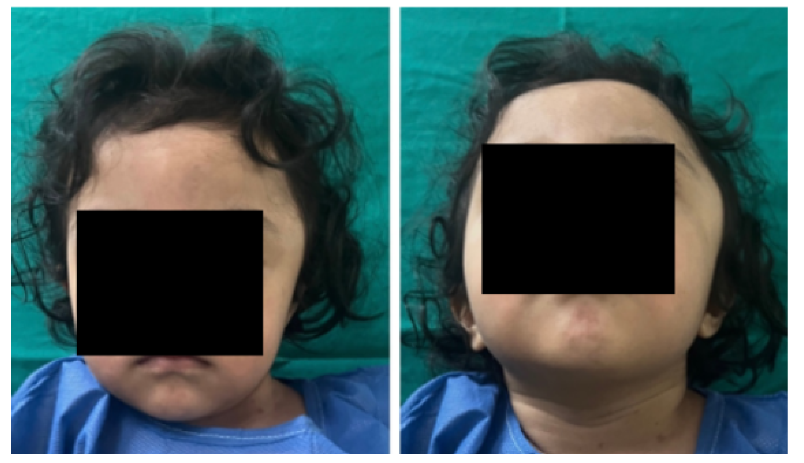
Figure 2.
Computed Tomography (CAT). Left temporoparietal cranial defect, solution of continuity in the roof of the orbit and temporoparietal region.
Figure 2.
Computed Tomography (CAT). Left temporoparietal cranial defect, solution of continuity in the roof of the orbit and temporoparietal region.
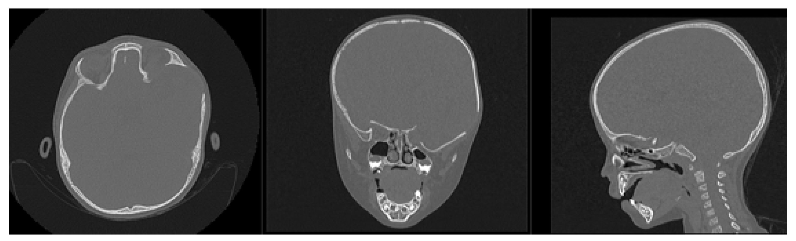
Figure 3.
Selection of the HU intensity (corresponding to the necessary bone density) from the tomographic image.
Figure 3.
Selection of the HU intensity (corresponding to the necessary bone density) from the tomographic image.
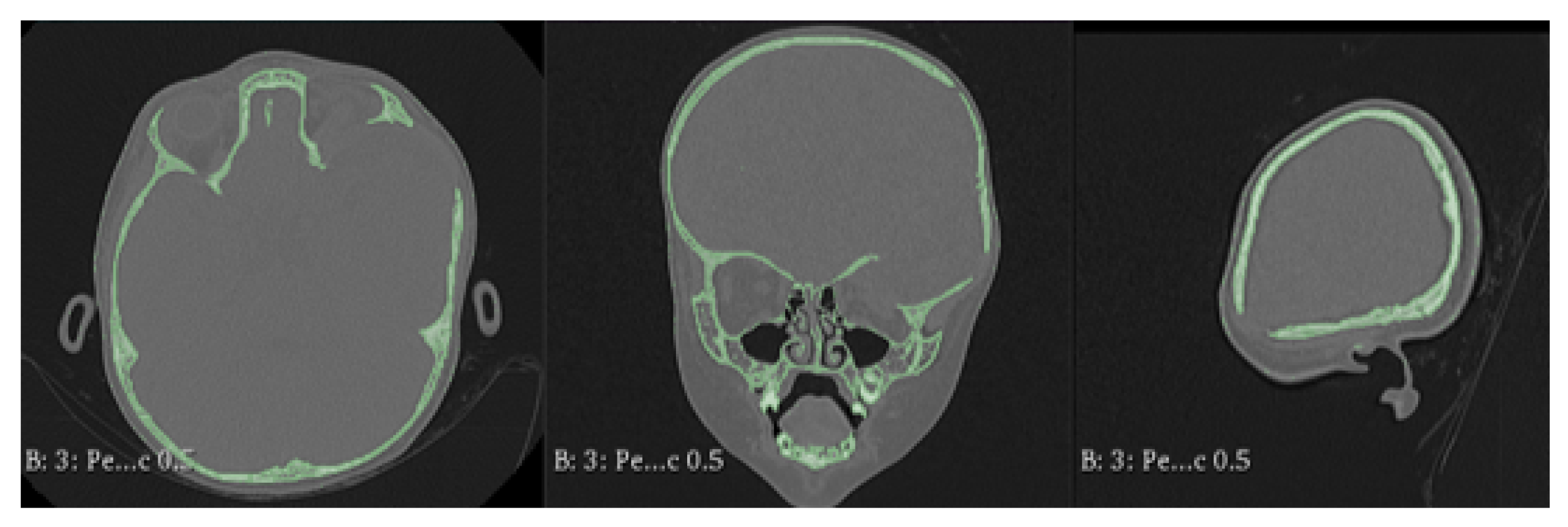
Figure 4.
Bone segmentation of the anatomical model with the cranial defect.
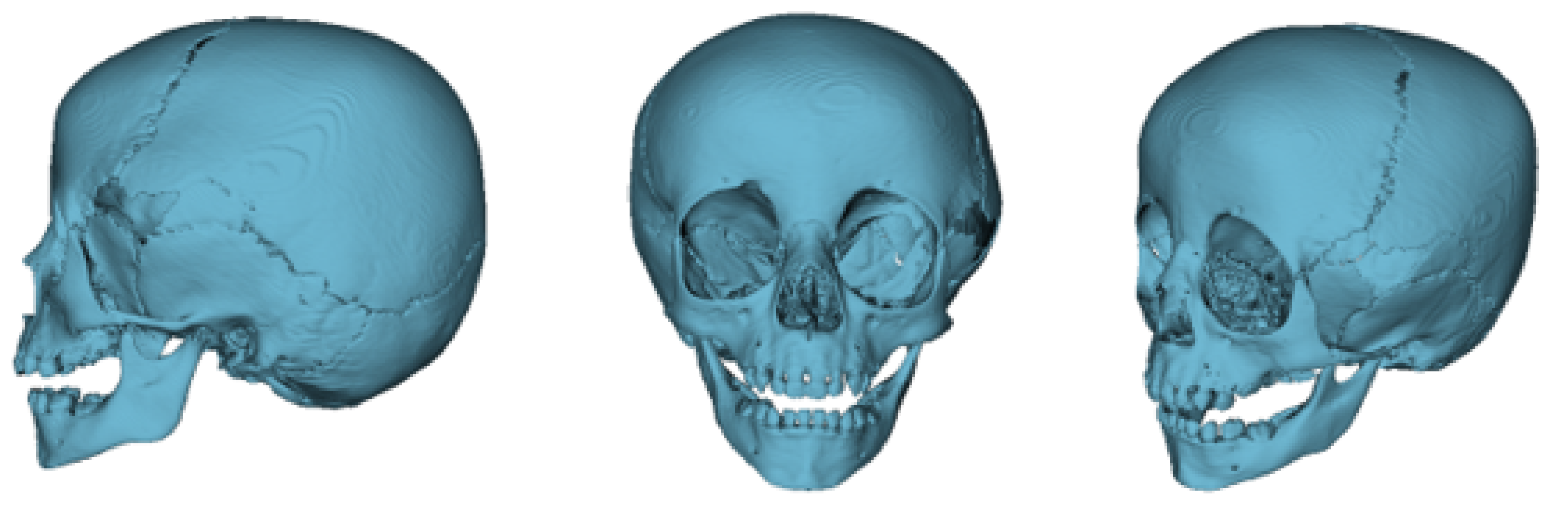
Figure 5.
Preparation of the 3D-printing model.
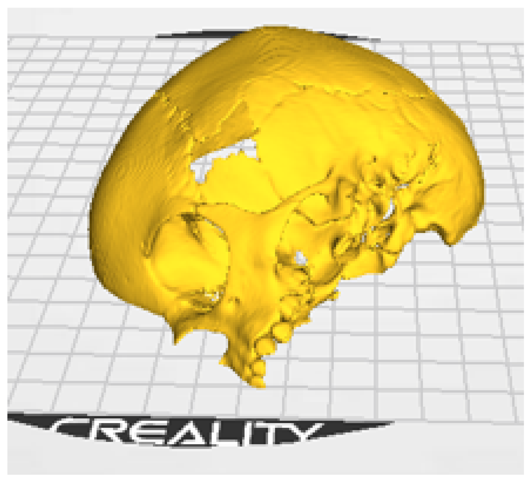
Figure 6.
3D-anatomical model of the skull and cutting plan.
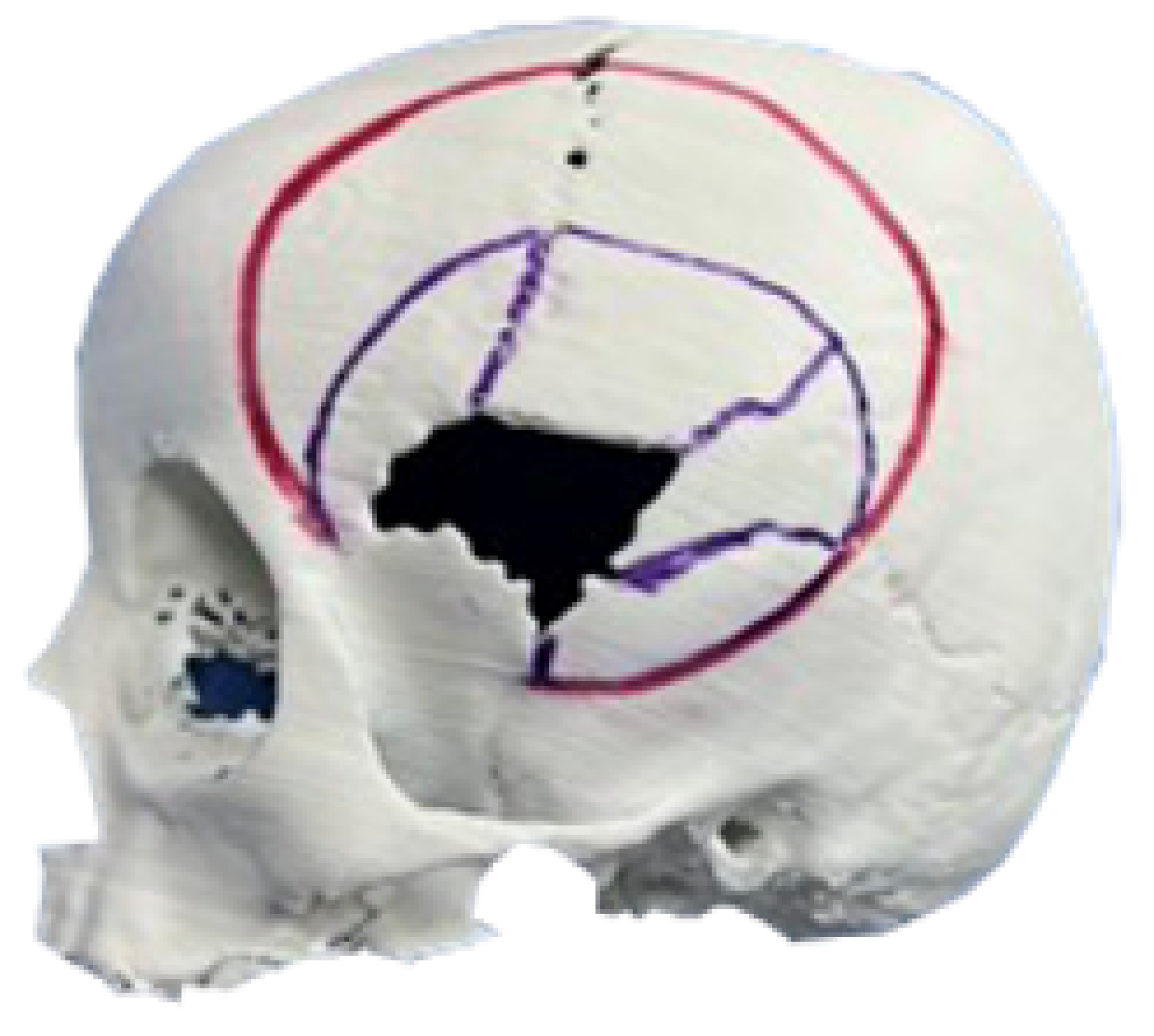
Figure 7.
Resected bone complex (top left). Bone complex with osteotomies (top right). Union of osteotomies and reconstruction of the temporoparietal bone defect with osteosynthesis (bottom left). Placement of orbital roof prosthesis for its reconstruction (bottom centre). Placement of reconstructed bone complex (bottom right).
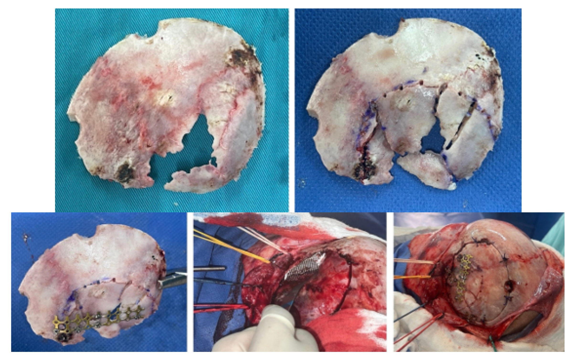
Figure 8.
Immediate postoperative tomographic control. The correction of the cranial defect, temporoparietal encephalocele, and the roof of the orbit are observed.
Figure 8.
Immediate postoperative tomographic control. The correction of the cranial defect, temporoparietal encephalocele, and the roof of the orbit are observed.
Figure 9.
Significant reduction of ocular proptosis and temporoparietal prominence is observed.
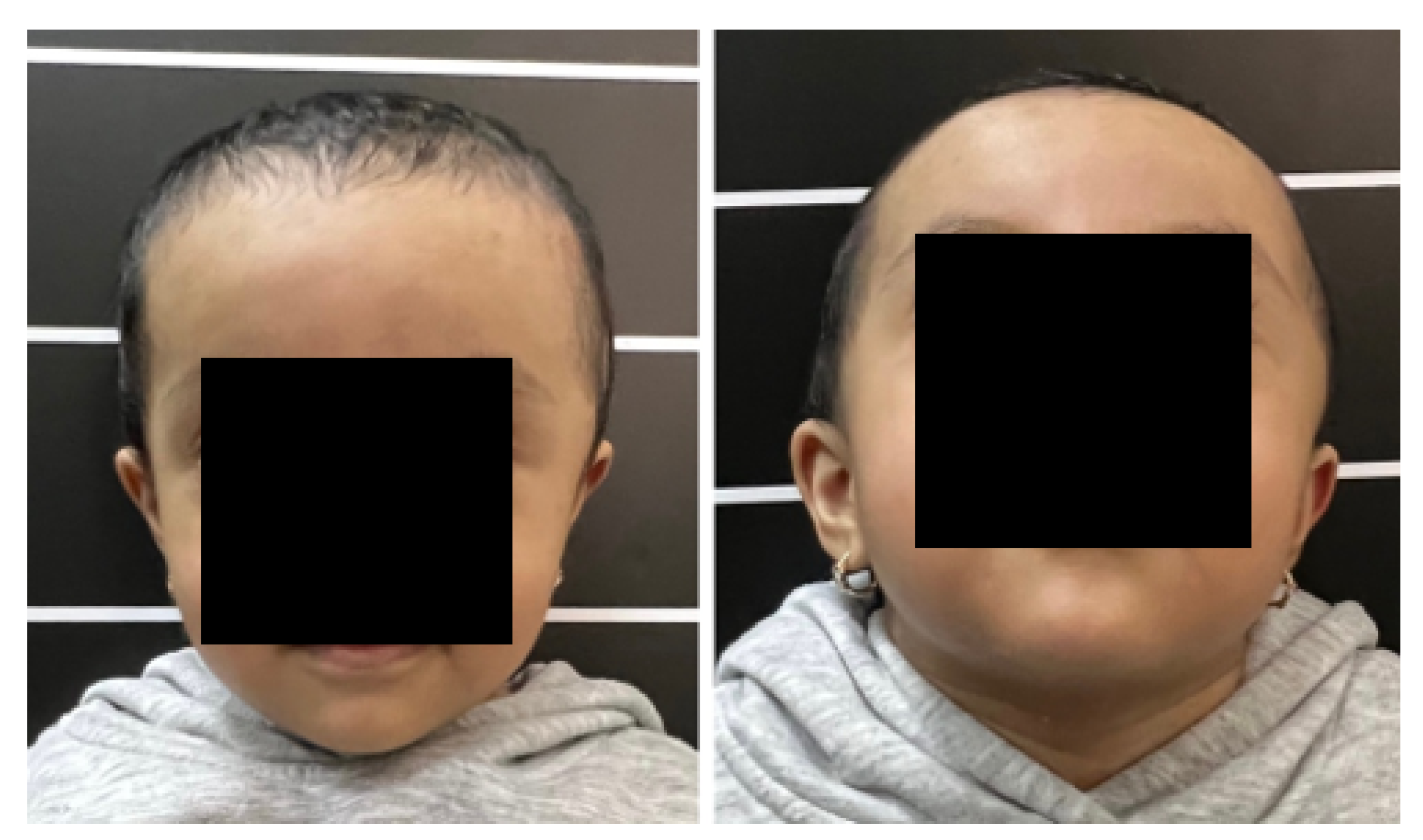
Figure 10.
Collapse in the left temporo-parieto-occipital region.
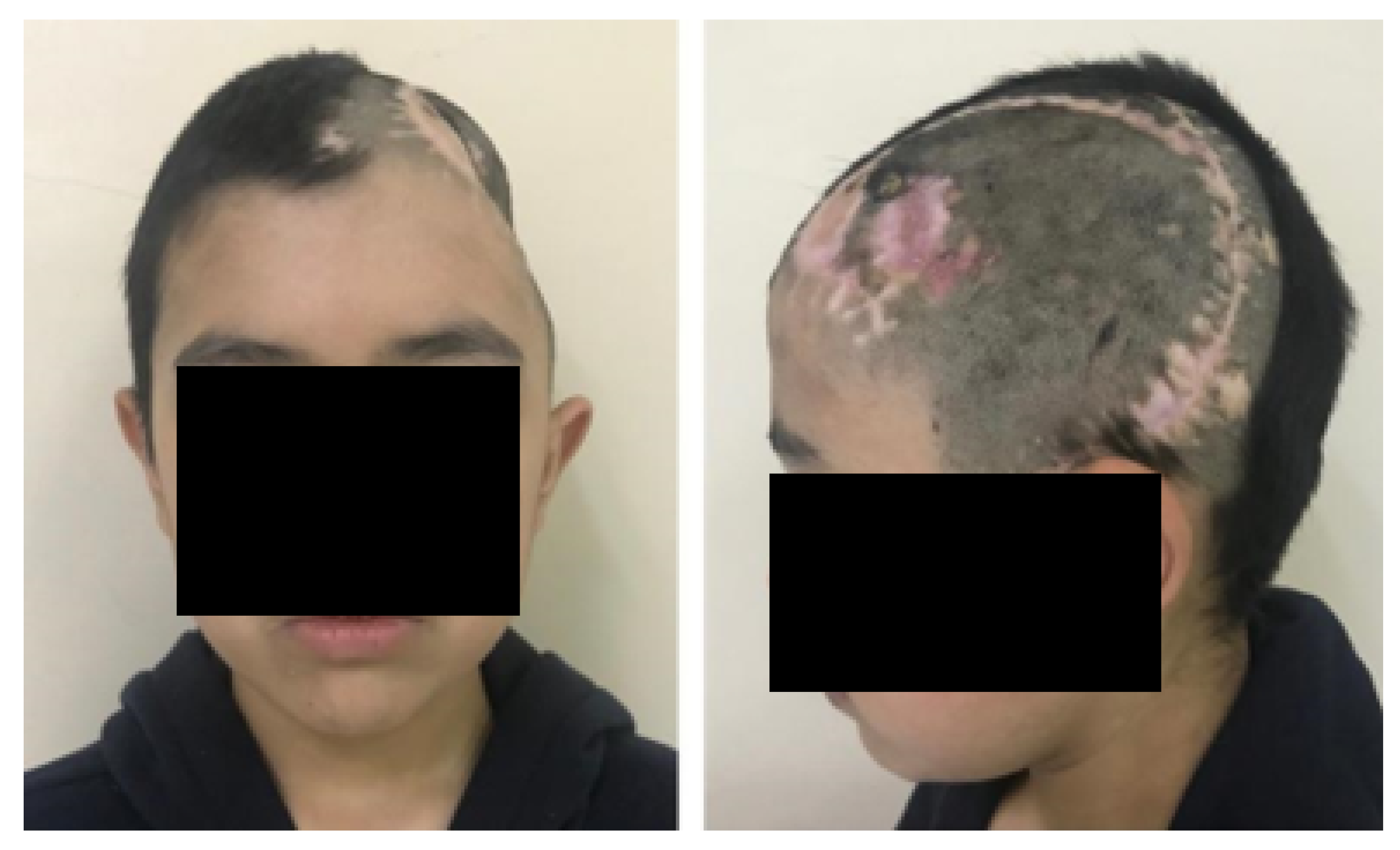
Figure 11.
TAC: sinking in the temporo-parieto-occipital region (left). Solution of bone continuity in the affected area (centre-right).
Figure 11.
TAC: sinking in the temporo-parieto-occipital region (left). Solution of bone continuity in the affected area (centre-right).
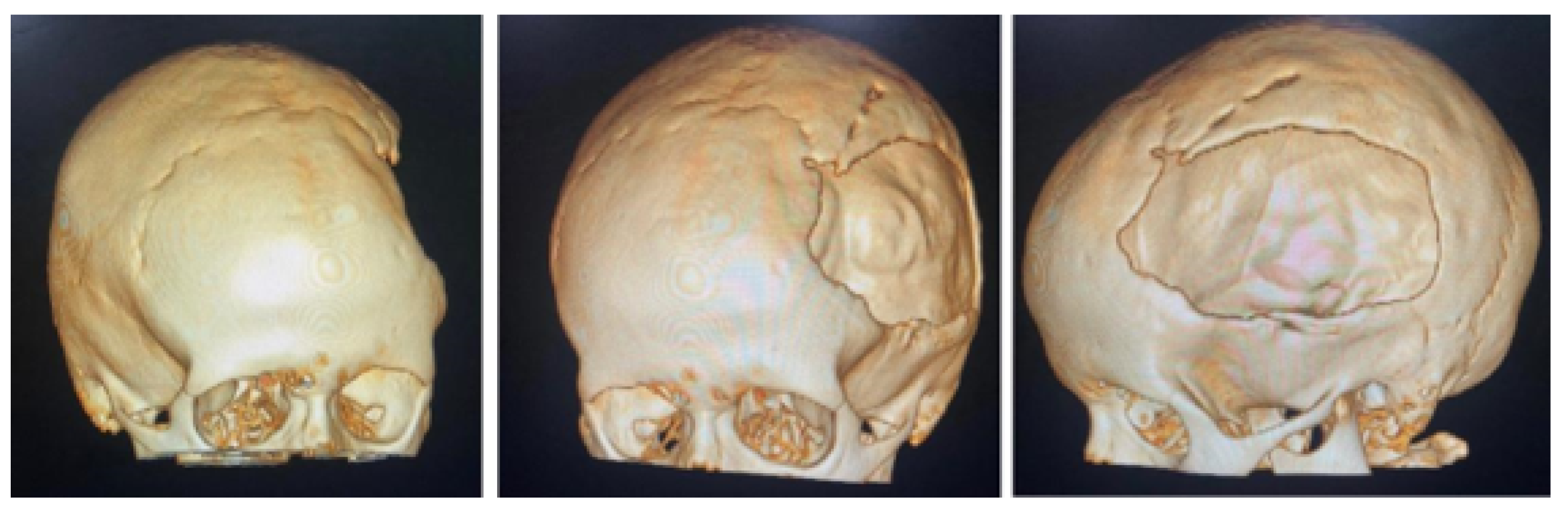
Figure 12.
Bone segmentation of the anatomical model from the tomographic image.
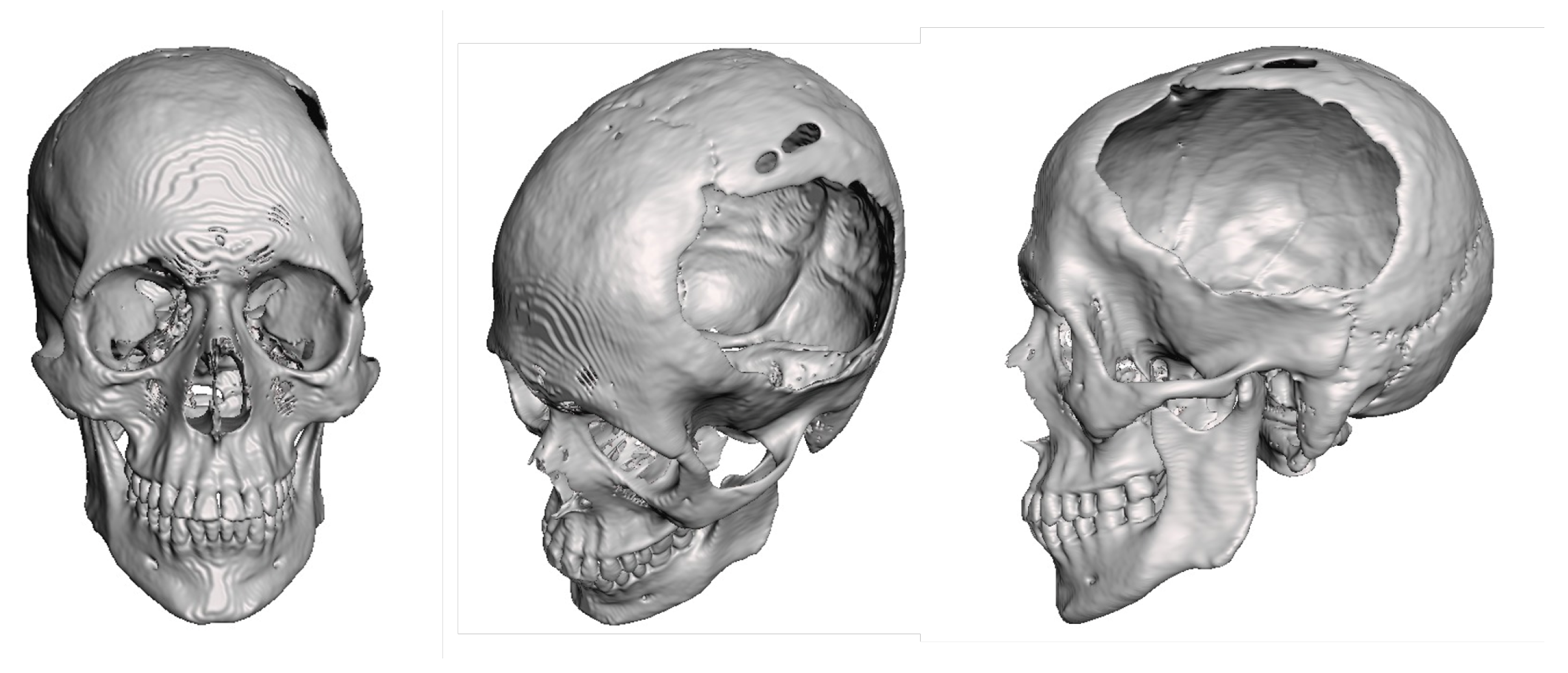
Figure 13.
3D anatomical model of the skull and non-implantable prosthesis (only for planning).
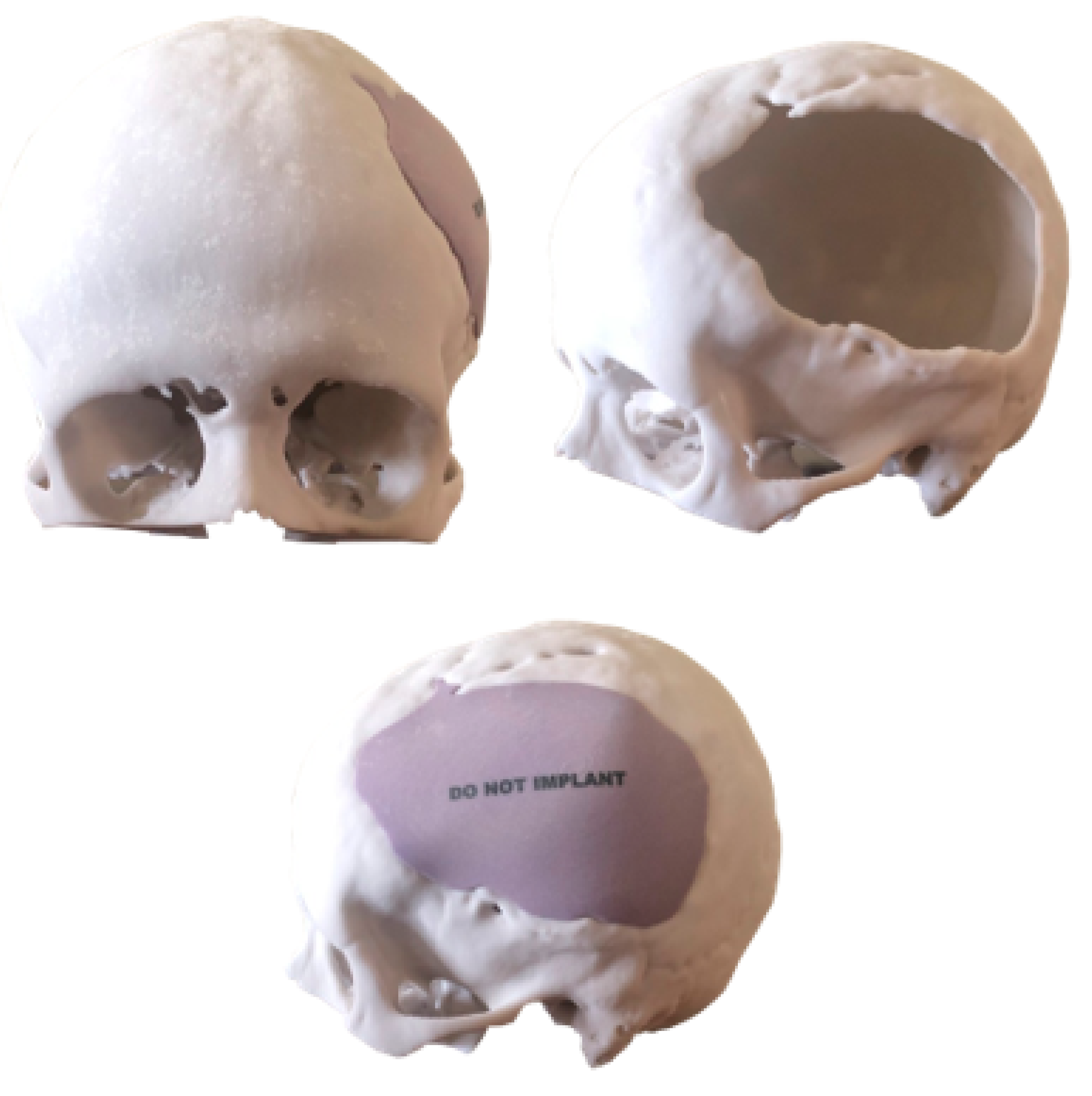
Figure 14.
3D patient-specific implant placement (left). Detail of implant fixation (right).
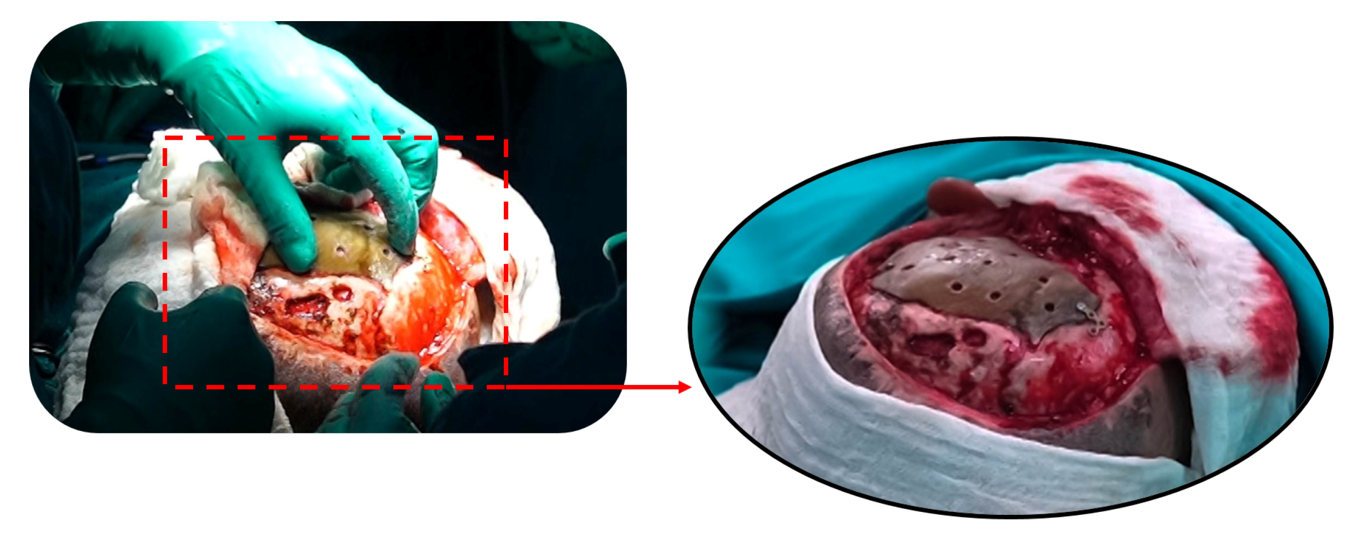
Figure 15.
Postoperative tomographic control. The reconstruction process has been successfully executed to a satisfactory degree.
Figure 15.
Postoperative tomographic control. The reconstruction process has been successfully executed to a satisfactory degree.
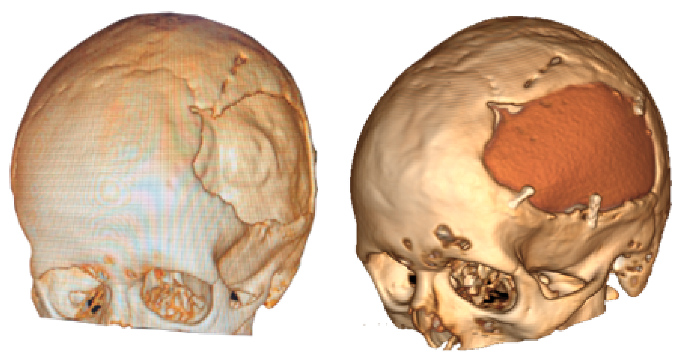
Figure 16.
Resolution of the cranial deformity.
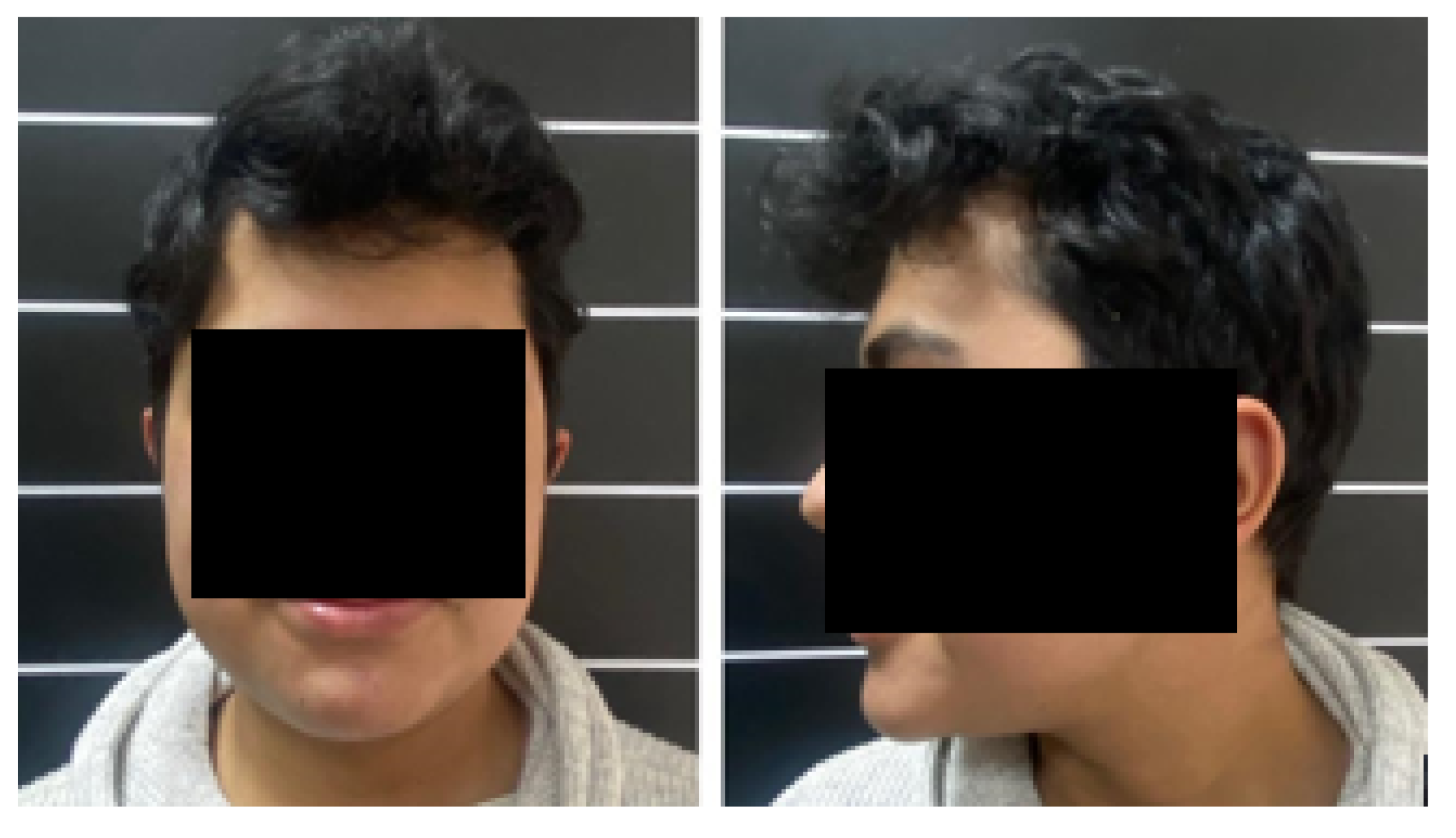
Figure 17.
Frontal tumour, ocular proptosis, enophthalmos.
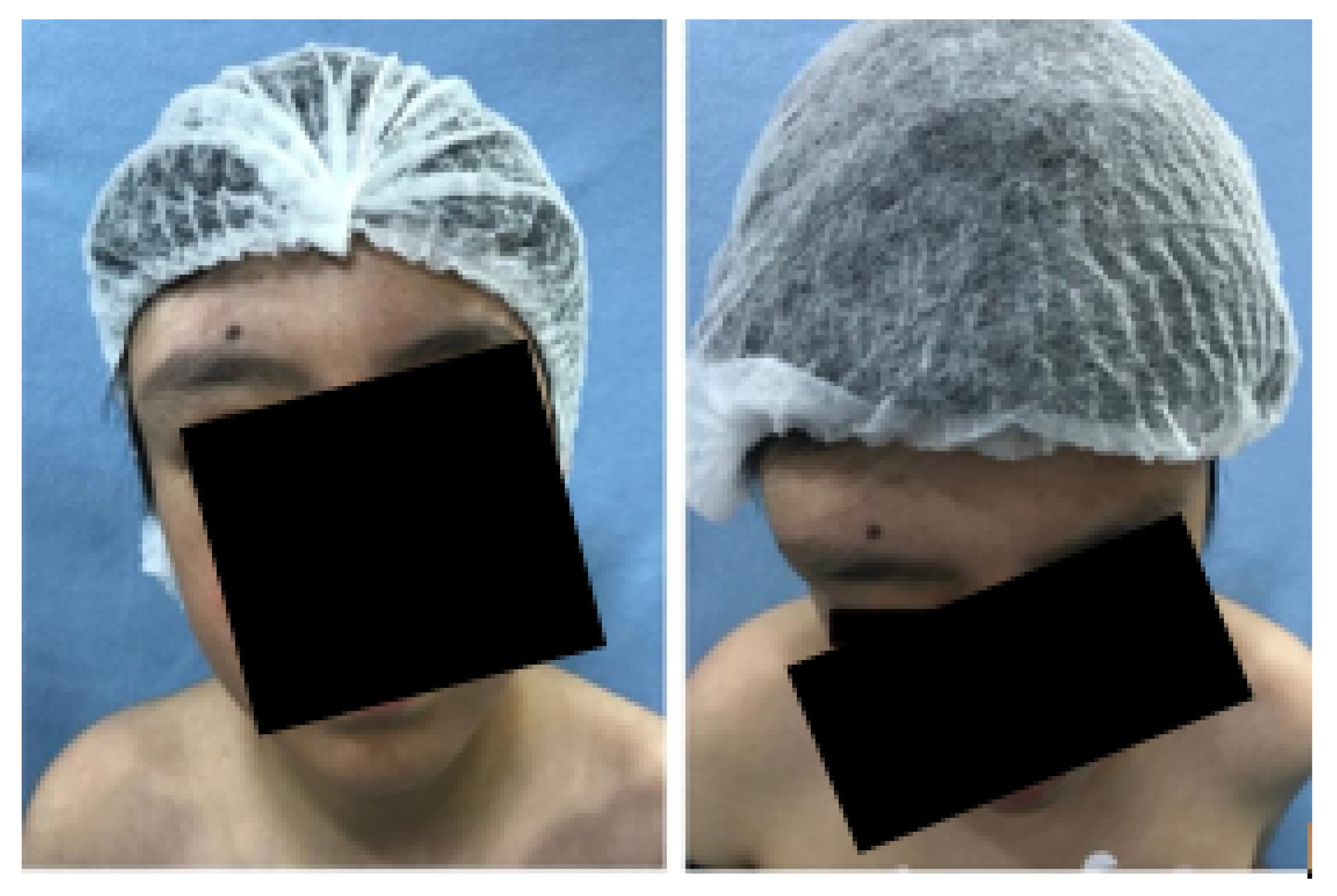
Figure 18.
CAT: 5-cm bone lesion in the roof of the orbit, paranasal sinus, and anterior vault of the skull.
Figure 18.
CAT: 5-cm bone lesion in the roof of the orbit, paranasal sinus, and anterior vault of the skull.
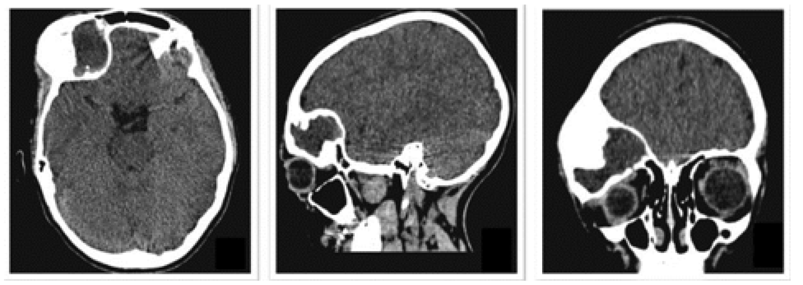
Figure 19.
Exposure of cranial damage from the tomographic image, and three-dimensional model.
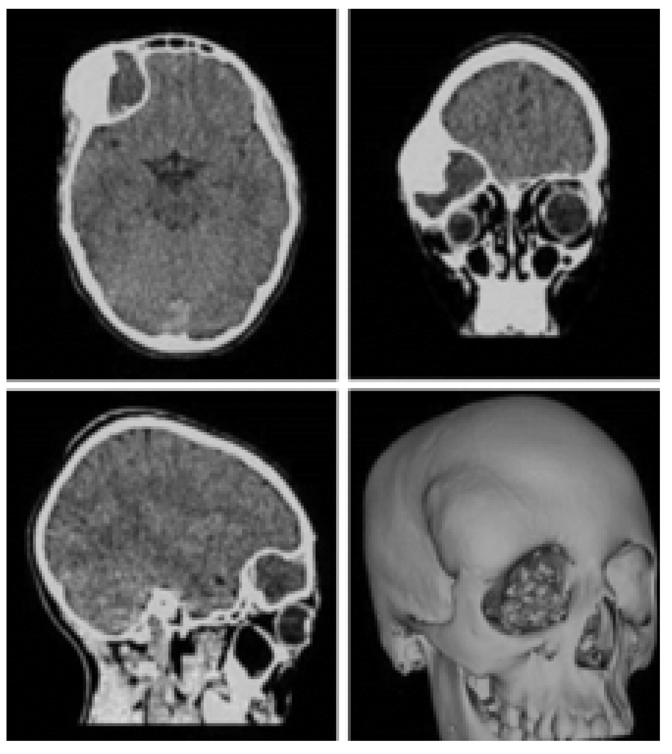
Figure 20.
3D printing of the anatomical model of the skull with the defect.
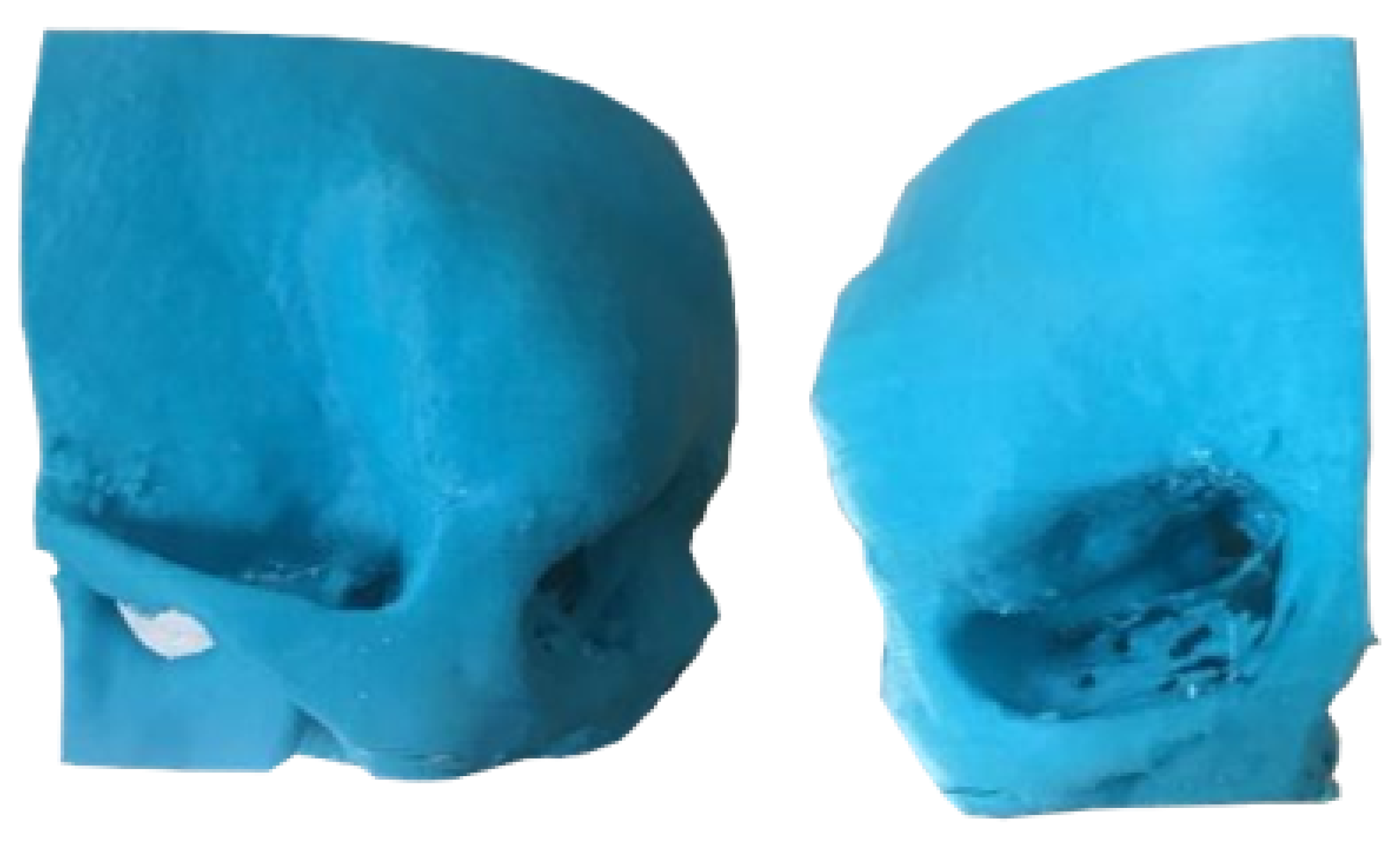
Figure 21.
Skull fixation for actual surgery (left). Placement of reconstructed bone complex (right).
Figure 21.
Skull fixation for actual surgery (left). Placement of reconstructed bone complex (right).
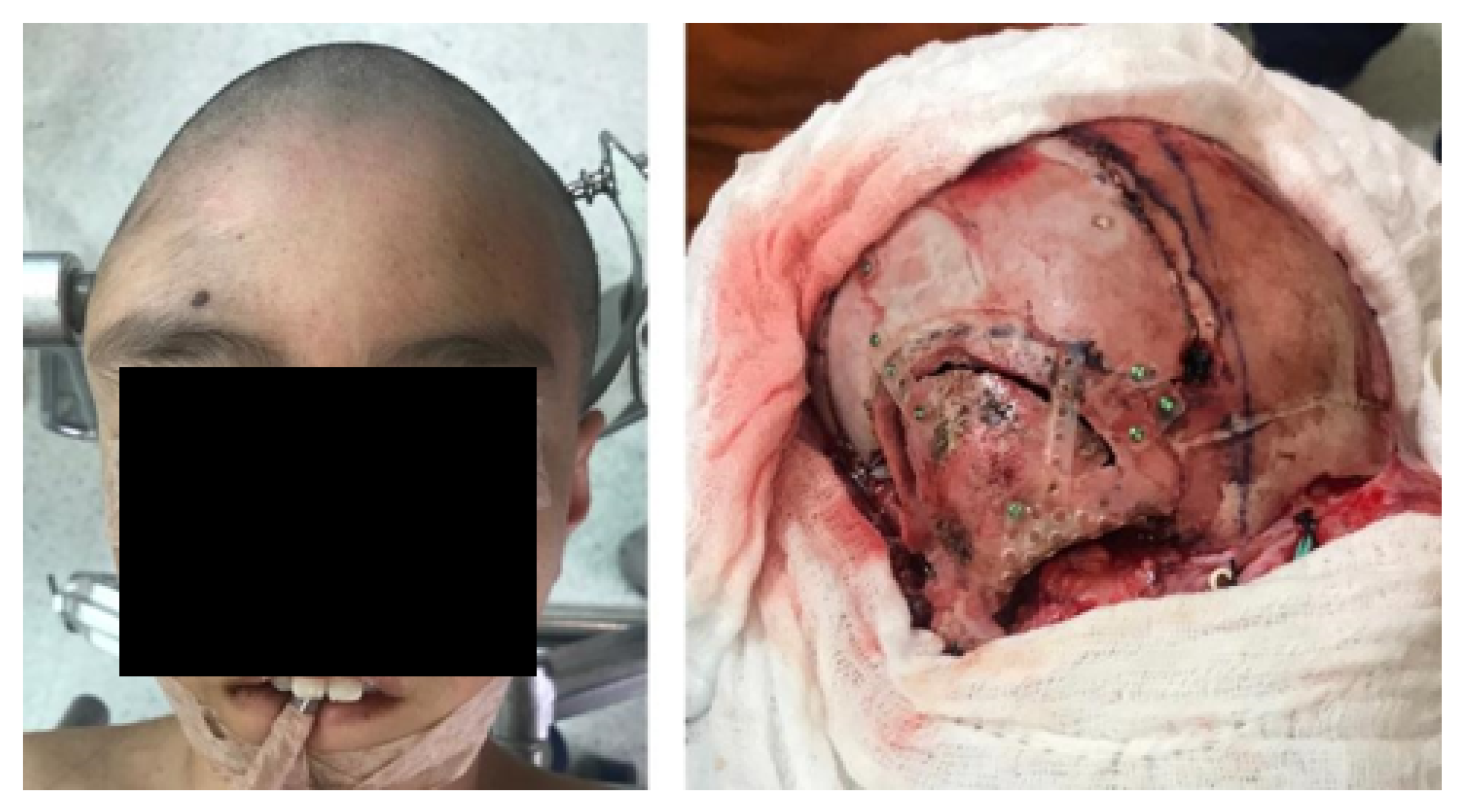
Figure 22.
Post-surgical tomography. Removal of the cranial tumour, frontoparietal and roof orbit reconstructions are observed.
Figure 22.
Post-surgical tomography. Removal of the cranial tumour, frontoparietal and roof orbit reconstructions are observed.
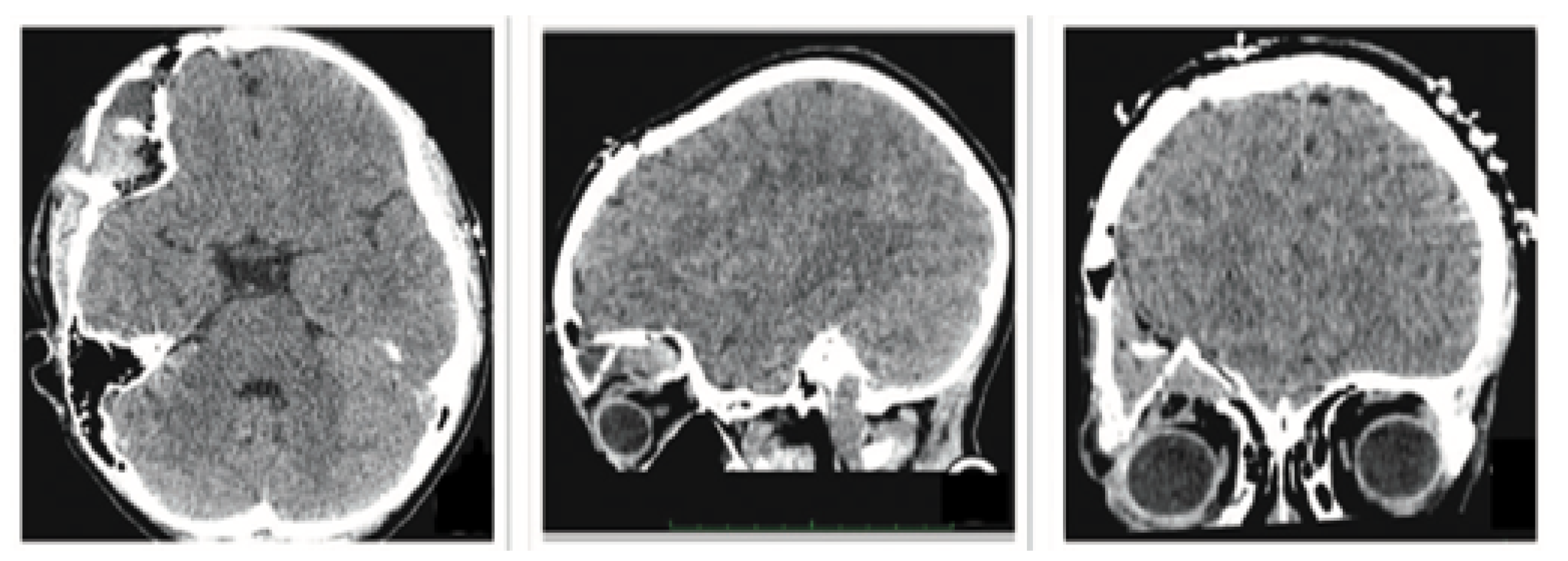
Figure 23.
Resolution of ocular proptosis and frontal zygomatic prominence.
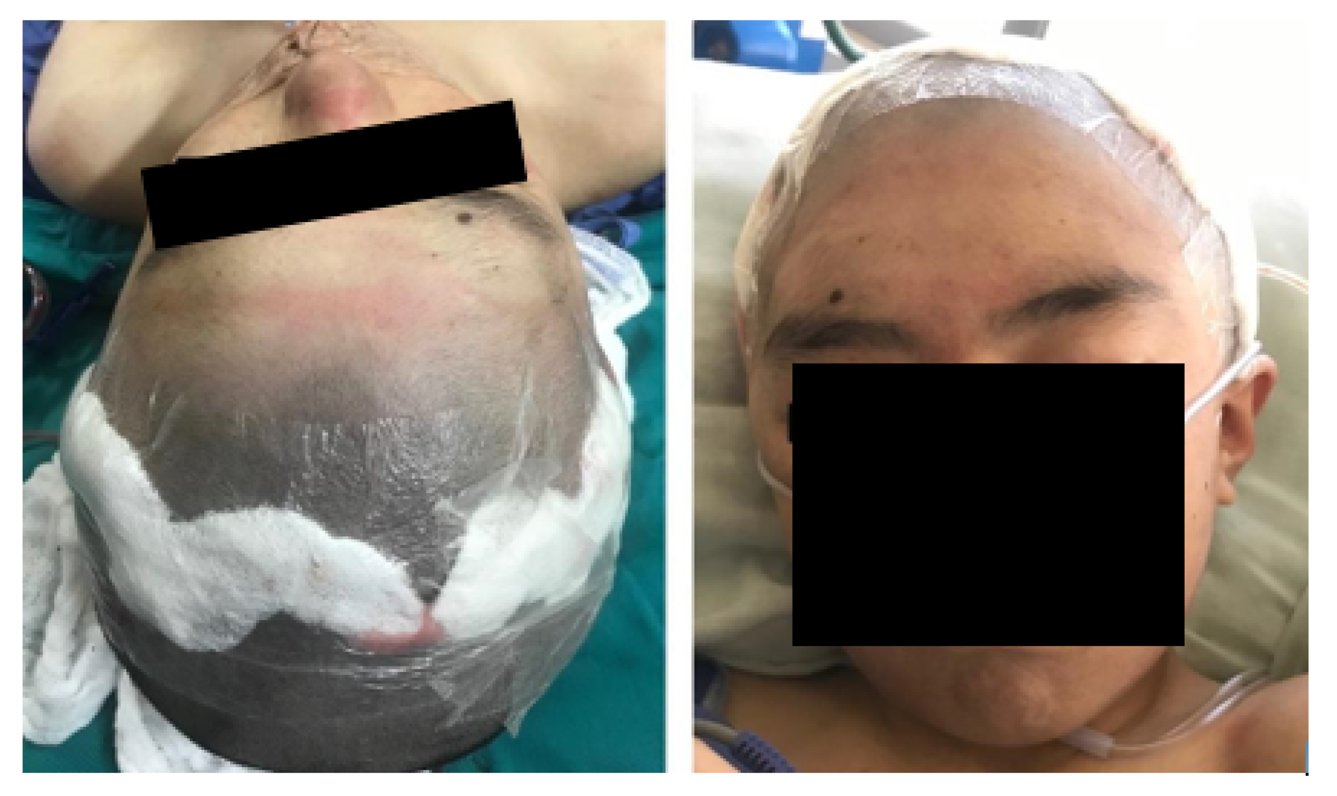
Figure 24.
Pre-surgical tomography.
Figure 25.
Virtual models: anatomical defect (left, yellow area), virtual model of the custom cutting guide (right, holes for fasteners and cutting slot shown).
Figure 25.
Virtual models: anatomical defect (left, yellow area), virtual model of the custom cutting guide (right, holes for fasteners and cutting slot shown).
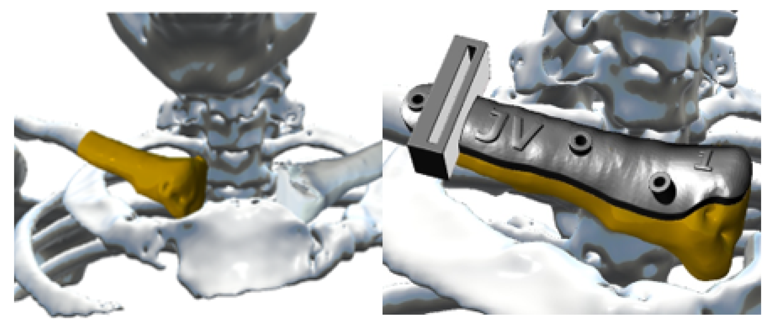
Figure 26.
Anterior view (left), showing joint damage. Posterior view (right), defects caused by osteosarcoma.
Figure 26.
Anterior view (left), showing joint damage. Posterior view (right), defects caused by osteosarcoma.
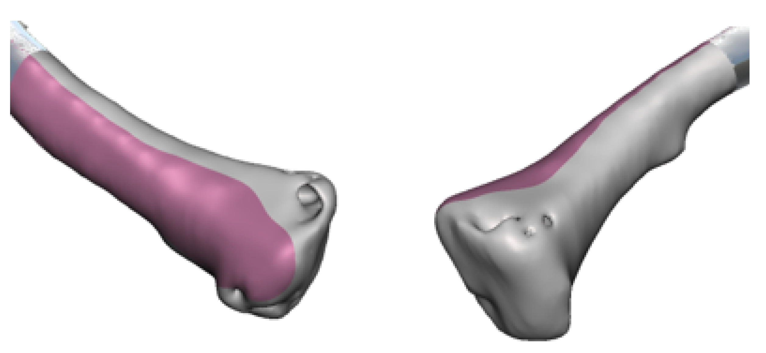
Figure 27.
Repaired virtual model: anterior view, undamaged joint (left). Posterior view, without osteosarcoma (right).
Figure 27.
Repaired virtual model: anterior view, undamaged joint (left). Posterior view, without osteosarcoma (right).
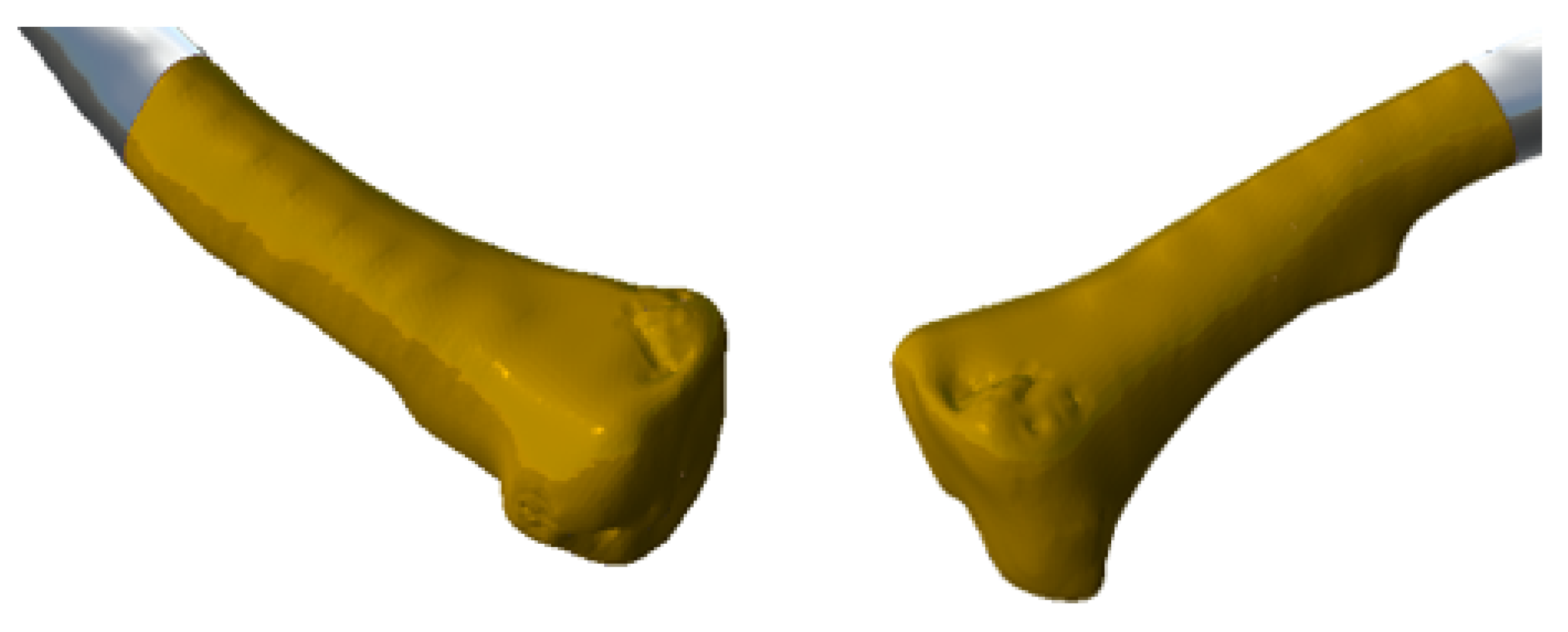
Figure 28.
Anatomical model, cutting guide and personalised prosthesis, printed in 3D.

Figure 29.
3D printed implant anatomical model.
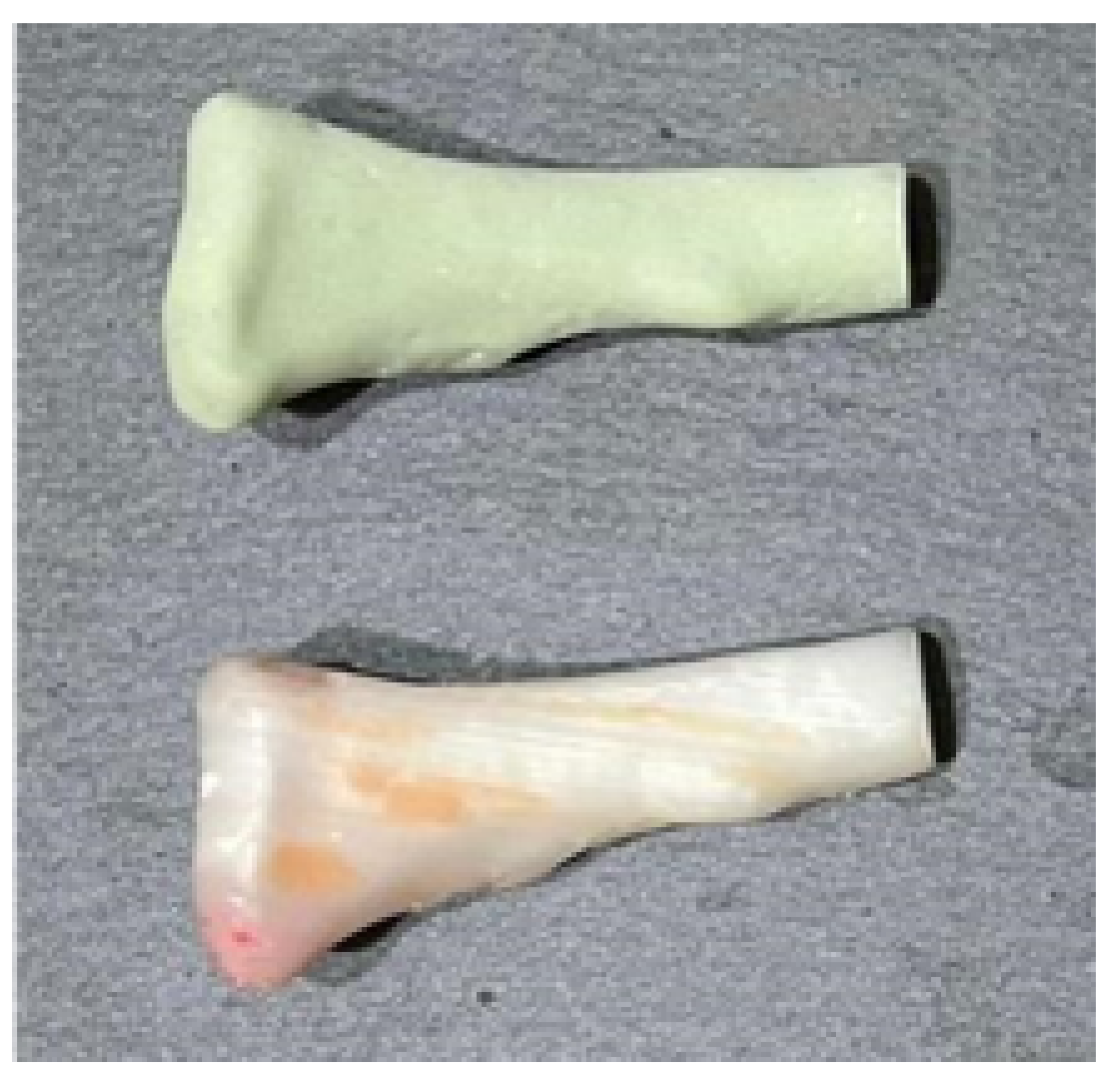
Figure 30.
Moments of surgery: Positioning and fixing the cutting guide (above). Removed the tumour alongside the anatomical test model and implant (bottom left). Implant fixation elements (bottom right).
Figure 30.
Moments of surgery: Positioning and fixing the cutting guide (above). Removed the tumour alongside the anatomical test model and implant (bottom left). Implant fixation elements (bottom right).
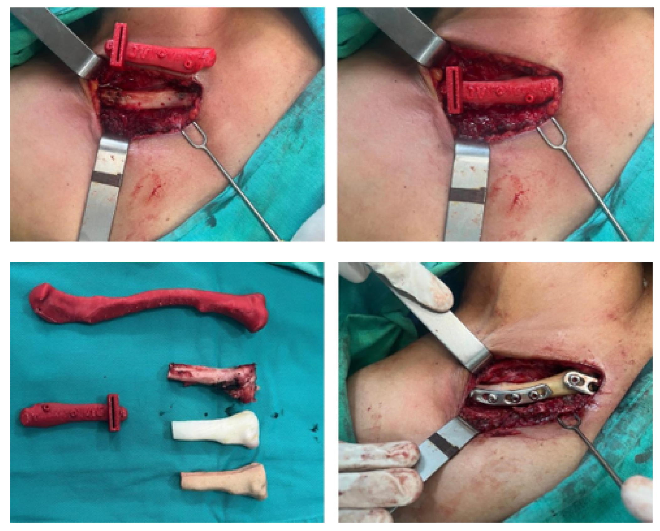
Figure 31.
Post-surgical tomography. Reconstruction of the right sternoclavicular joint after tumour excision.
Figure 31.
Post-surgical tomography. Reconstruction of the right sternoclavicular joint after tumour excision.
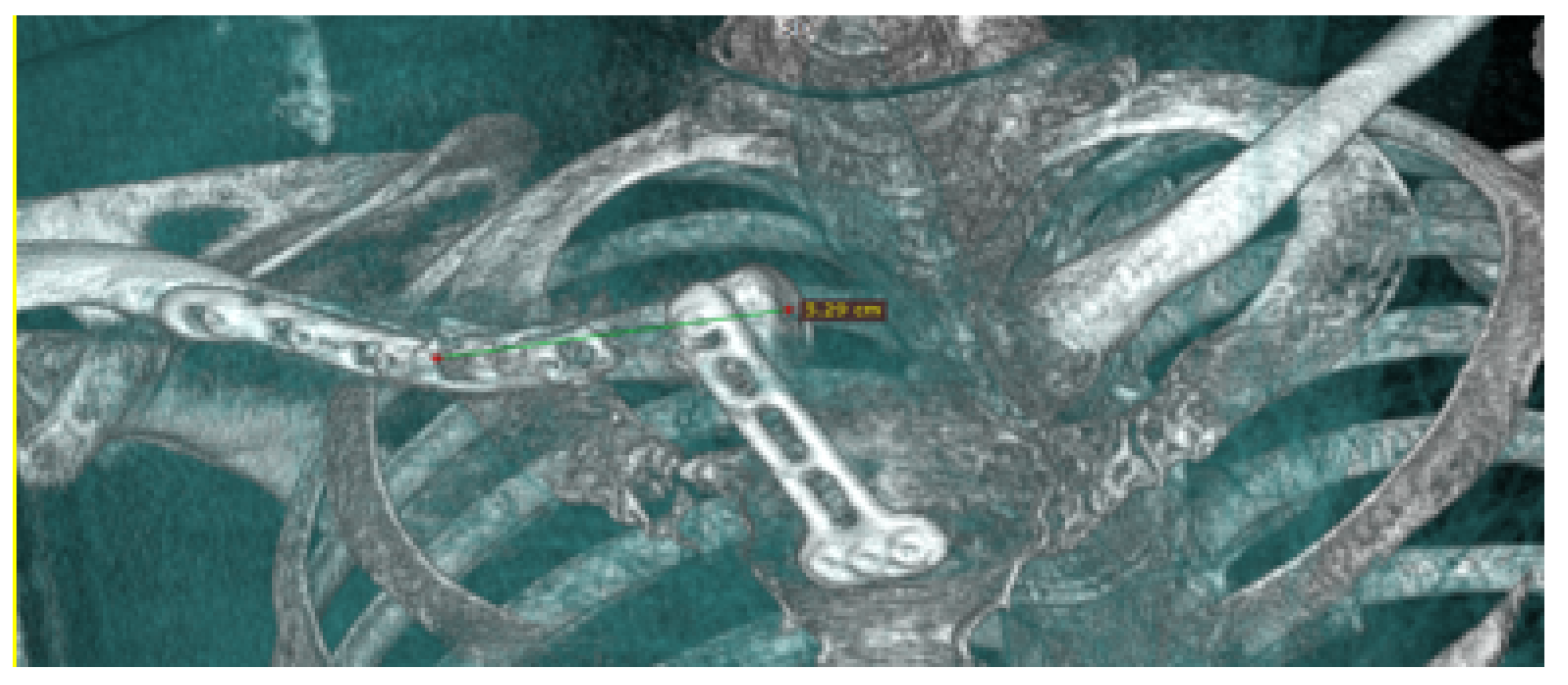
Figure 32.
External views of the thoracic tumour.
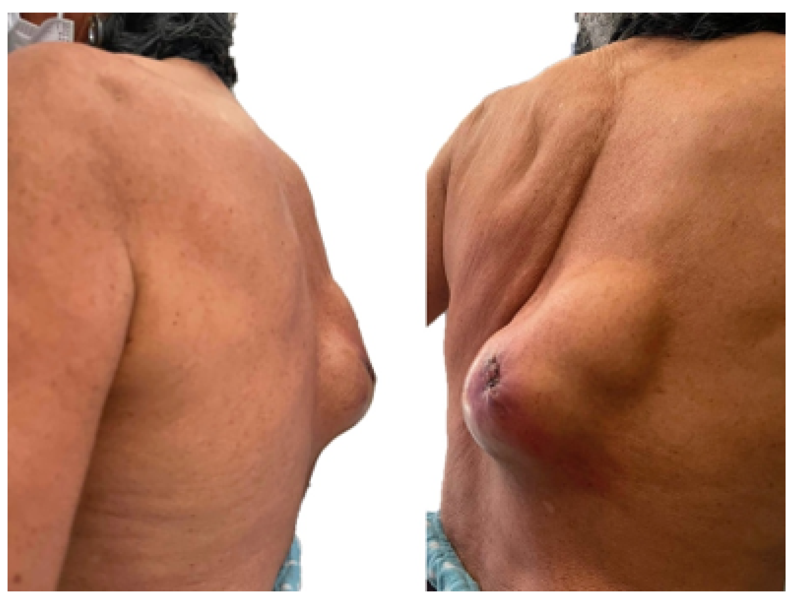
Figure 33.
Tomographic image that reveals involvement of the skin, subcutaneous cellular tissue, soft tissues, and rib grill with pleura invasion.
Figure 33.
Tomographic image that reveals involvement of the skin, subcutaneous cellular tissue, soft tissues, and rib grill with pleura invasion.
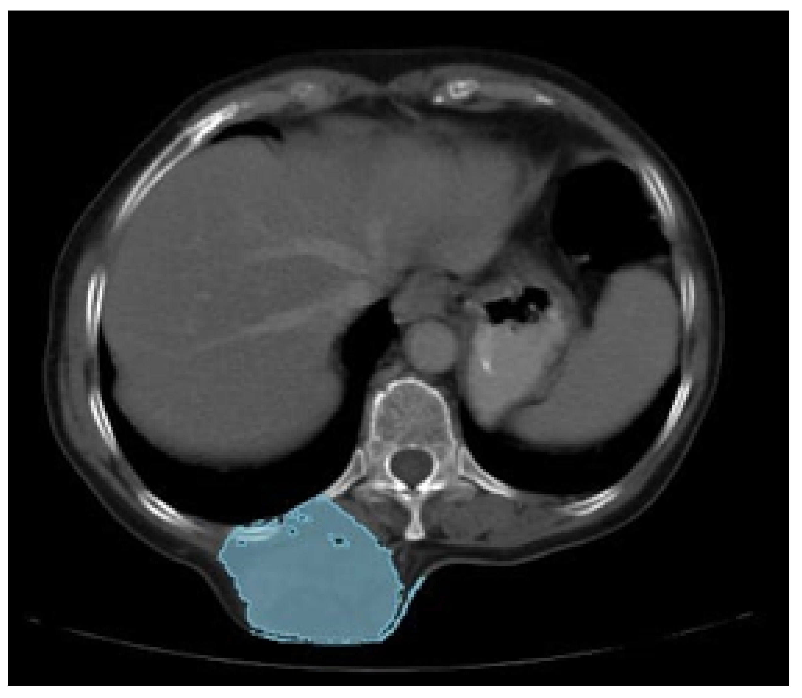
Figure 34.
Anatomical model printing process (left). Cutting guide (right).
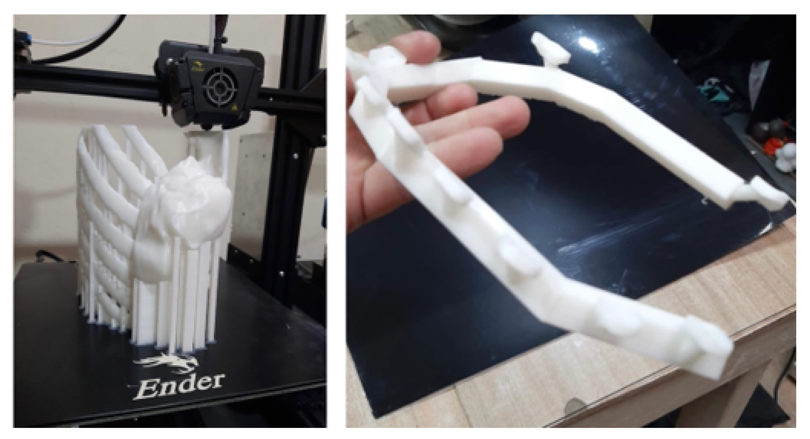
Figure 35.
Detail of the cutting guide (left). Anatomical test model with the tumour (right).
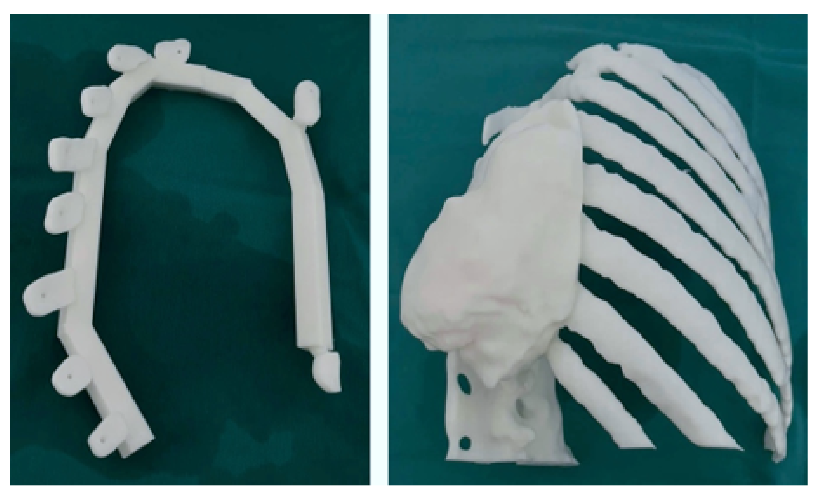
Figure 36.
Excision of the tumour through limits marked by the cutting guide.
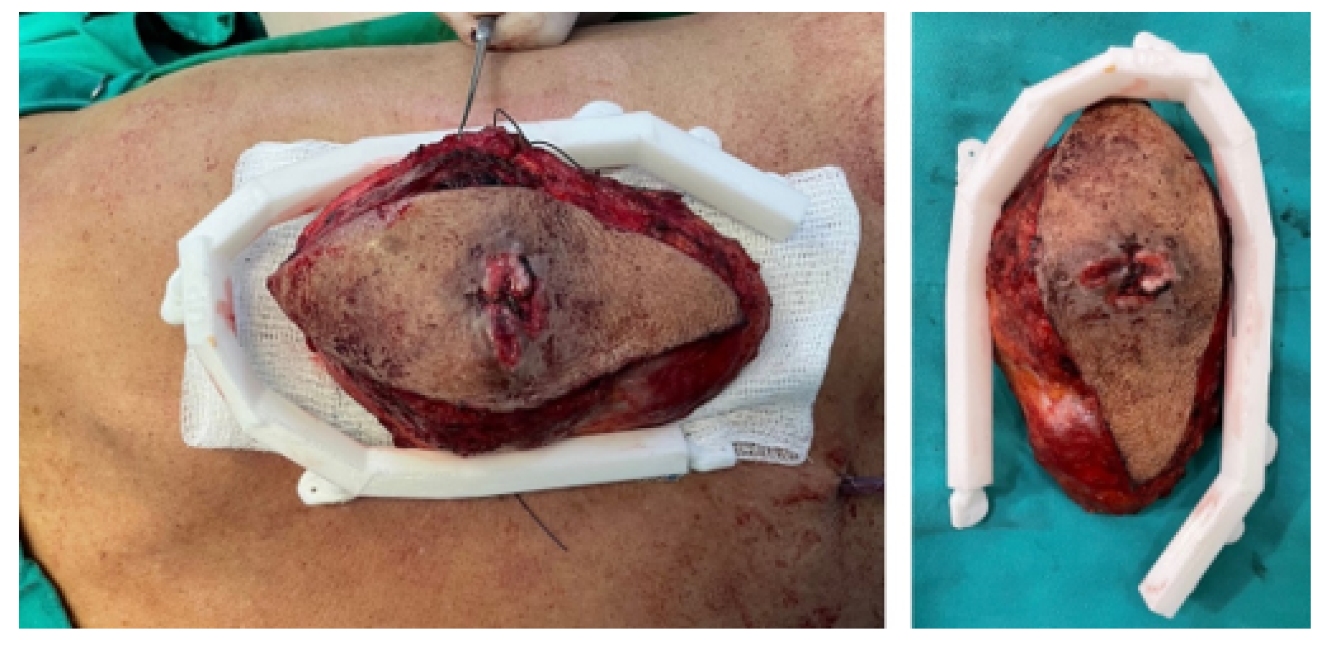
Figure 37.
Reconstruction of the posterior chest wall.
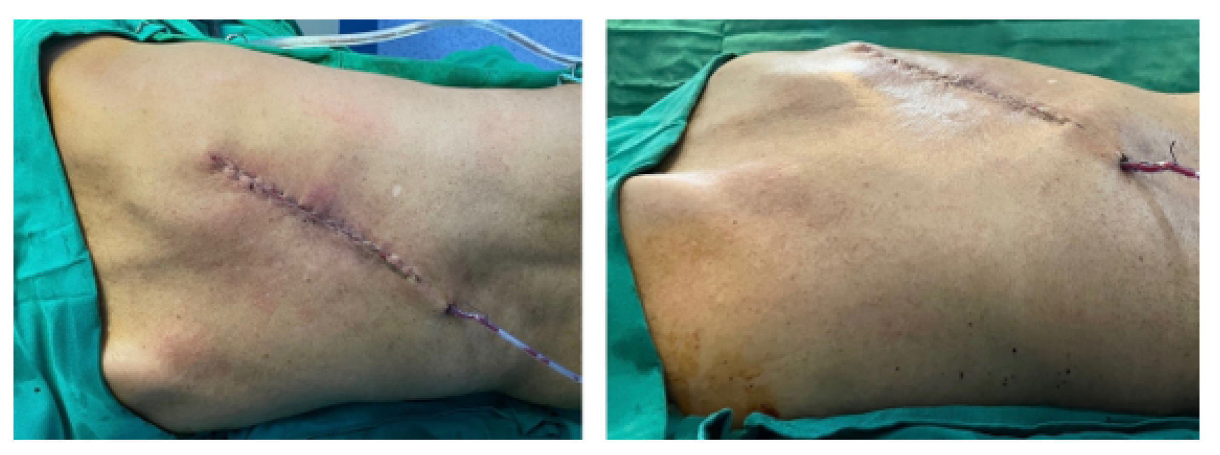
Figure 38.
Isolation of the clavicular tumour (left). Clavicle and sternum reconstruction model (right).
Figure 38.
Isolation of the clavicular tumour (left). Clavicle and sternum reconstruction model (right).
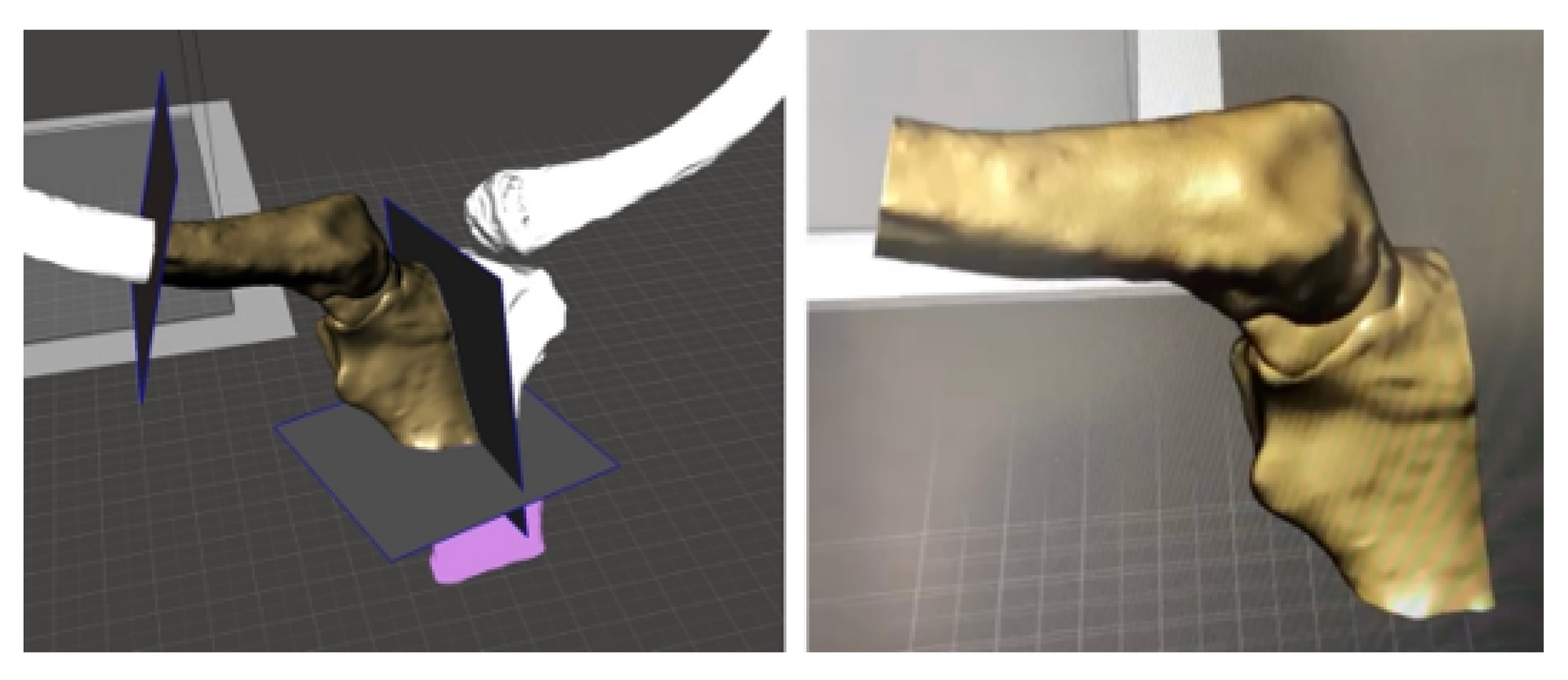
Figure 39.
Bone segmentation model and anatomical reconstruction (left). Anatomical positioning of the cutting guide (right).
Figure 39.
Bone segmentation model and anatomical reconstruction (left). Anatomical positioning of the cutting guide (right).
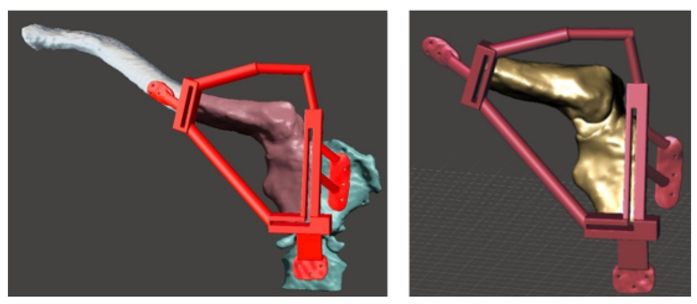
Figure 40.
Anatomical model printed in PLA and BioMed white resin-based cutting guide (left). PMMA-based custom implant (right).
Figure 40.
Anatomical model printed in PLA and BioMed white resin-based cutting guide (left). PMMA-based custom implant (right).
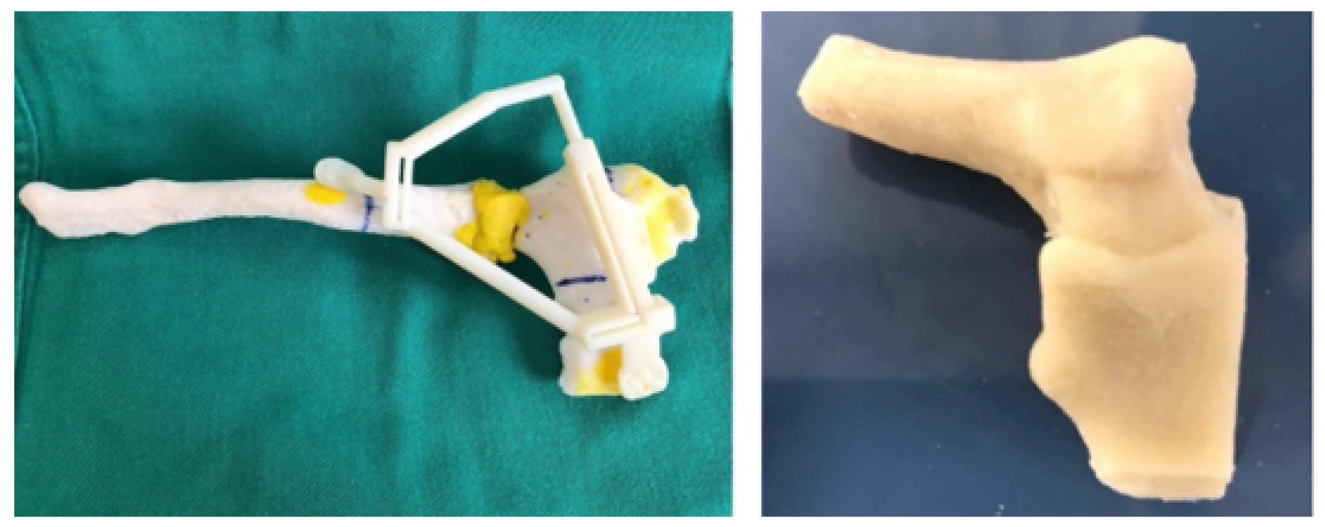
Figure 41.
Surgery details: Positioning the cutting guide (top, left). Space left by the excision of the tumour (top, right). Placement of the custom implant (bottom, left). Implant fixation (bottom, right).
Figure 41.
Surgery details: Positioning the cutting guide (top, left). Space left by the excision of the tumour (top, right). Placement of the custom implant (bottom, left). Implant fixation (bottom, right).
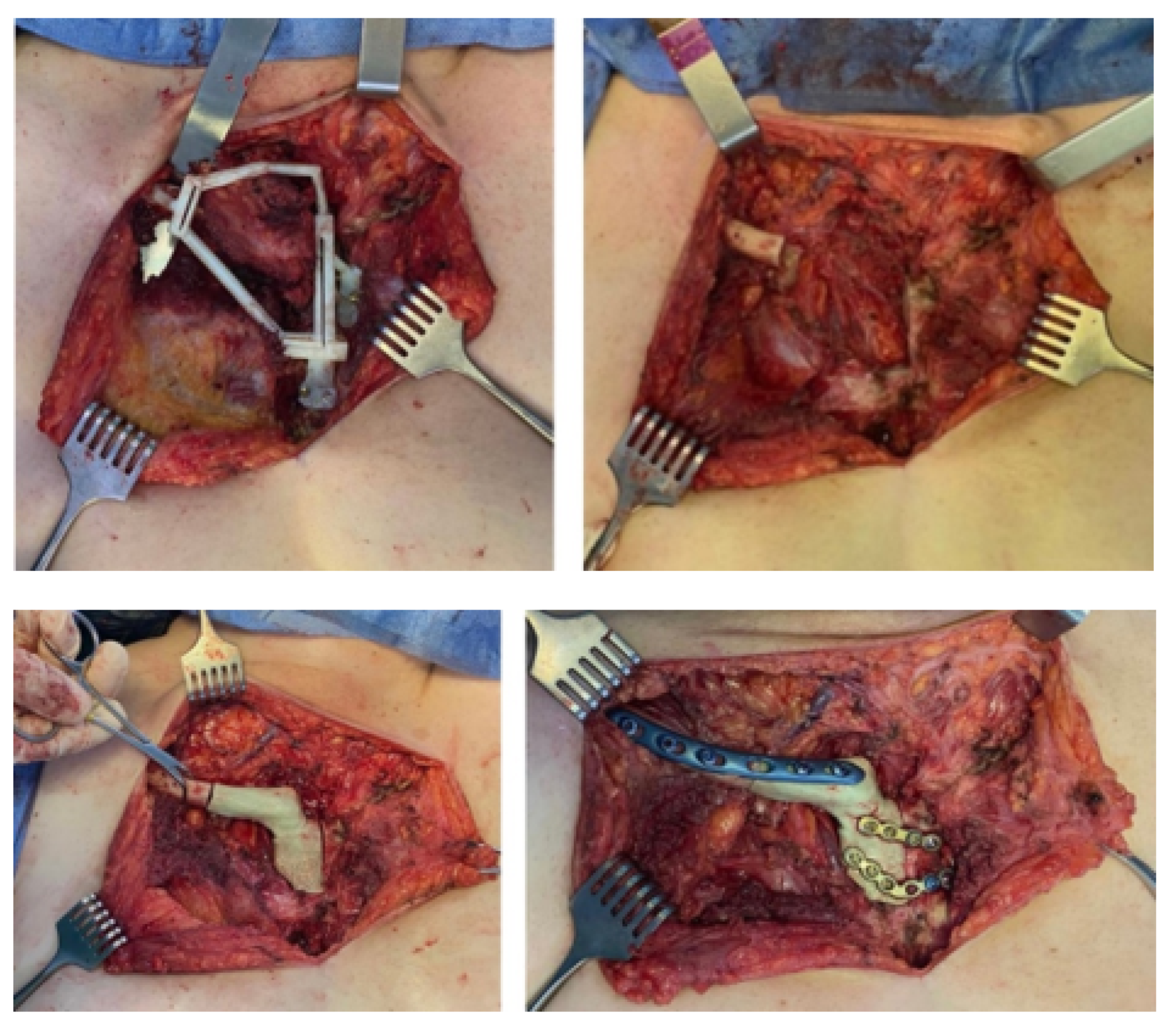
Figure 42.
Right sternoclavicular reconstruction after tumour excision (tomographic image).
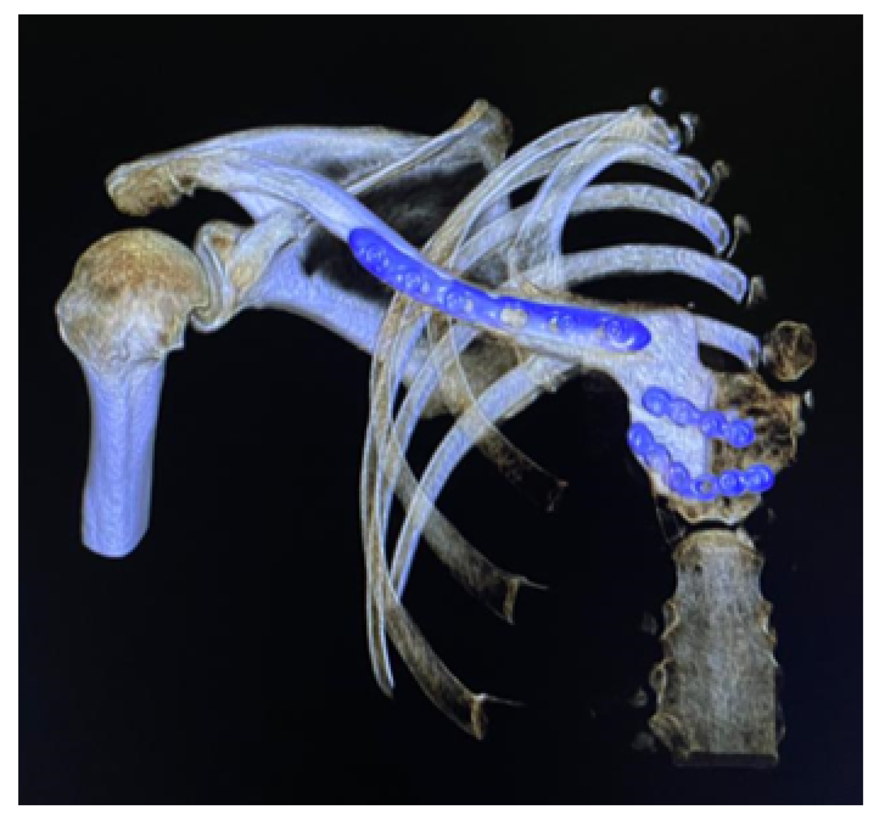
Figure 43.
Different aspects of deformity identification (tomographic image).
Figure 44.
Anatomical test model of the skull (left). Test model of the cutting guide and planning of cuts on the cranial bone (right).
Figure 44.
Anatomical test model of the skull (left). Test model of the cutting guide and planning of cuts on the cranial bone (right).
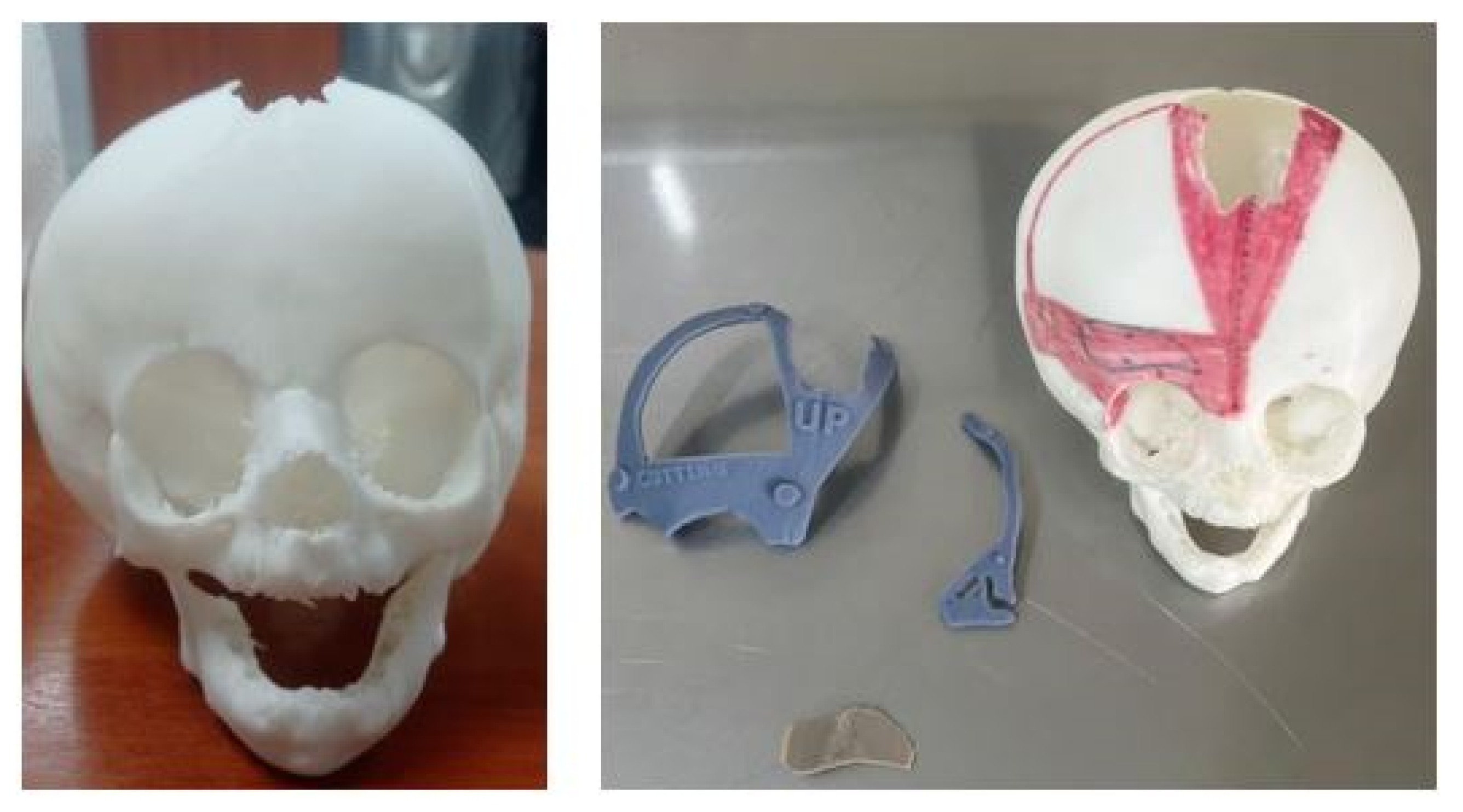
Figure 45.
Digital models of the skull and the cutting guide.
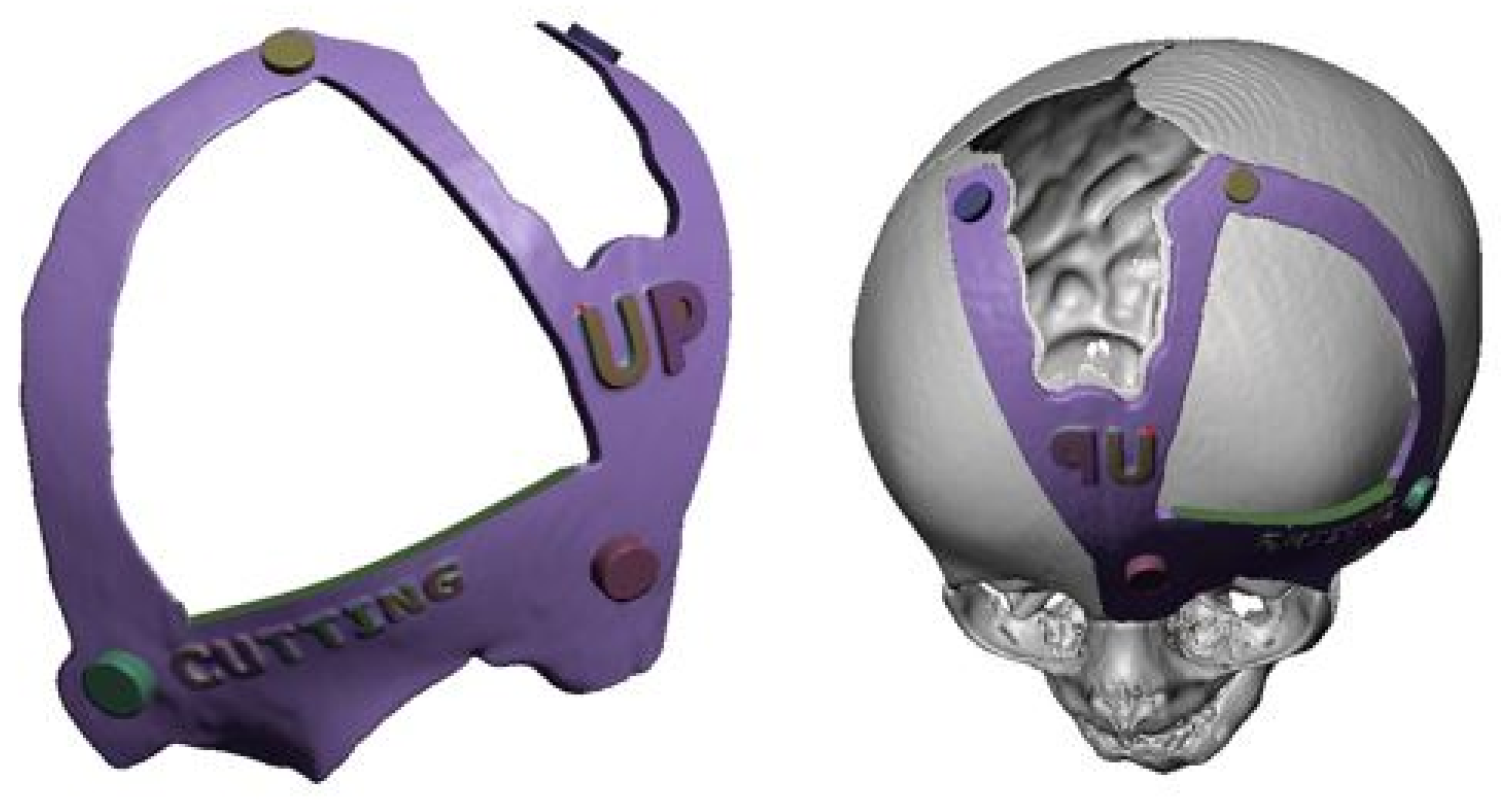
Figure 46.
Before surgery (left). Bone distraction for positioning the frontal bone block (top right). After surgery (bottom right).
Figure 46.
Before surgery (left). Bone distraction for positioning the frontal bone block (top right). After surgery (bottom right).
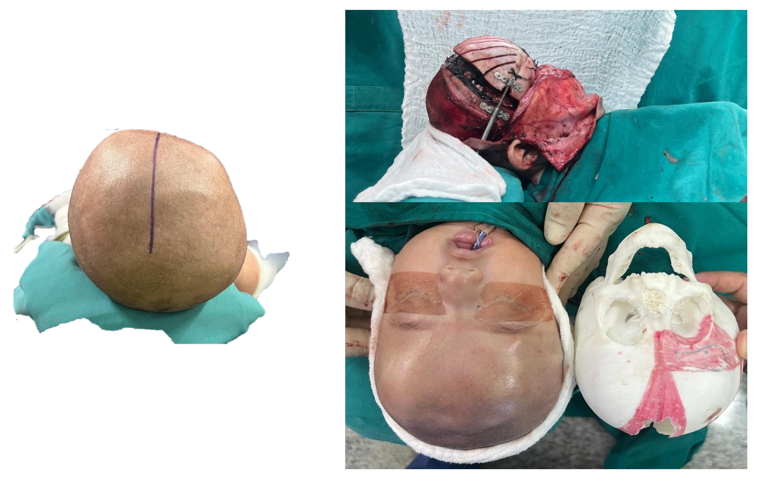

Table 1.
FDM additive manufacturing characteristics and parameters.
| Characteristics and manufacturing parameters | Fused Deposition Modeling (FDM) |
|---|---|
| Company and model | Creality CR-X Pro (2019 Updated) |
| Maximum build envelope | |
| Nozzle diameter | |
| Positioning resolution | |
| Selected layer thickness | |
| Printed filament line width |
Table 2.
Characteristics of the polymers that were utilised in this study.
| Characteristics | PLA (FDM) | PMMA | Resin PolyJet |
|---|---|---|---|
| Polymer | Thermoplastic | Thermoplastic | Photopolymer |
| Manufacturer | Creality HP | Veracril, New Stetic S.A. | Stratasys |
| Commercial | HP-PLA | PMMA | MED610 |
| Color | White (Bone) | Transparent | Transparent |
| Density | |||
| Tensile strength | |||
| Print/molding temperature | |||
| Filament diameter | - | - | |
| Printed diameter | - | - |
Disclaimer/Publisher’s Note: The statements, opinions and data contained in all publications are solely those of the individual author(s) and contributor(s) and not of MDPI and/or the editor(s). MDPI and/or the editor(s) disclaim responsibility for any injury to people or property resulting from any ideas, methods, instructions or products referred to in the content. |
© 2025 by the authors. Licensee MDPI, Basel, Switzerland. This article is an open access article distributed under the terms and conditions of the Creative Commons Attribution (CC BY) license (http://creativecommons.org/licenses/by/4.0/).
Copyright: This open access article is published under a Creative Commons CC BY 4.0 license, which permit the free download, distribution, and reuse, provided that the author and preprint are cited in any reuse.


