Submitted:
13 July 2025
Posted:
15 July 2025
You are already at the latest version
Abstract
This technical report presents PACFramework (PFw), an open framework designed to support the development of application software for programmable controllers (PLC/PAC) and SCADA/HMI systems. PFw addresses common challenges in industrial automation by offering a structured, reusable, and standardized software architecture based on international standards such as ISA-88, ISA-95, and IEC 61131. The framework incorporates engineering best practices for diagnostics, alarm handling, simulation, contextual variable modeling, and system integration. Supporting tools, such as PFwTools and PFwIoTGateway, enable automated code generation, commissioning, and integration with IIoT and MES platforms. Drawing on years of practical experience, PFw is suitable for a wide range of industrial projects, from small-scale systems to complex multi-device architectures. The report also outlines the motivation and roadmap for PFw2, the next version of the framework, aimed at deeper integration with DevOps principles and Digital Twin technologies.
Keywords:
PLC
; PAC
; software framework
; software engineering
Table of Contents
PacFramework: Technological Solutions for PLC/PAC Programming 1
Introduction 4
1. Background and Motivation 6
Using Different Platforms 7
Process Visibility (Situational Awareness) 7
Alarm Subsystem 8
Equipment Diagnostics 9
Fault Handling 10
System Commissioning 10
Operator Training 11
Design-Phase Changes 11
Integration with MES/MOM and Other Subsystems 12
A Common Language 13
A Unified Software Development Standard and Team Collaboration 13
Balancing Functionality with Resource Constraints 13
Integration into IIoT Systems 13
2. What Is PACFramework 14
Definition of PFw 14
Purpose 14
Key Characteristics 15
Related Projects 16
PFwTools 16
PFwIoTGateway 18
PFw2 Infrastructure 19
3. Core Technologies Behind the Framework 20
Standards 21
Equipment Concept 22
State Based Control 24
State 24
State Machines 26
Modes 30
Transition Conditions and Commands 31
Propagation of Modes and States Between Objects 32
Equipment Hierarchy 32
Definition of Equipment Hierarchy 32
Equipment Hierarchy in ISA-88 (IEC 61512) 35
IoT Technologies 36
Overview of Other Technologies Used 37
Hardware Abstraction 37
Built-In PLC Simulation Models 38
4. Technological Solutions in PFw 38
Equipment Hierarchy 38
CM Hierarchy 39
Typical Modes 41
PLC Class and Object 41
Channels (LVL0) and PLC Map 42
Process Variables (LVL1) and Variable Map 45
Control Modules, Loops, Actuators (LVL2) 47
General Requirements for the Implementation of PACFramework POU, Function and Function Block Interfaces 48
Structure of Function/Procedure and Function Block Interfaces 48
ID та CLSID 49
Principles of Using Buffered Exchange with SCADA/HMI 49
State (STA) and Command (CMD) Variables 52
Data type requirements 53
Object Classification and Customization Concept 53
Classes (CLSID) 53
Parameters 53
State Variables (STA) 54
Methods for Adapting an Algorithm to Execute Special Actions for Specific Objects (Customization) 54
General Principles for SCADA/HMI Development 55
5. Conclusions 56
References 56
Introduction
In the IT industry, complexity has been successfully simplified. Programmers once had to manually configure environments, gather dependencies, and execute numerous scripts. Today, they rely on tools like Git, Docker, CI/CD, and frameworks that offer clear rules for building projects. These advances allow developers to concentrate on creating value rather than constantly battling routine tasks.
But what about industrial automation? Manual transfers of programs between PLCs are still widespread. Projects are often copied and pasted, with inconsistent code structures even within the same organization or from the same vendor. The absence of centralized version control and a well-defined architecture makes collaboration and system maintenance challenging. The issue is not a shortage of skilled engineers, but rather the lack of standardized DevOps practices and open frameworks to simplify and unify the development of control system software.
To help address these challenges, PACFramework (PFw) was developed. It is an open framework comprising a set of interconnected rules, guidelines, data structures, and software components. PFw is primarily intended for developing application software for programmable devices such as industrial controllers (PLC/PAC), though its use is not limited to them. The framework is based on typical control system requirements, international standards (ISA, IEC, ISO), and modern trends such as Industry 4.0 and IIoT. It enables rapid development of PLC/PAC and SCADA/HMI software for industrial automation systems, supporting all types of processes - continuous, discrete, and batch. PFw can be applied to any programmable device intended for monitoring and control.
Since PACFramework (PFw) was introduced as an open project in 2017 and published in a GitHub repository [1], it has undergone significant evolution. The framework has taken shape as a collection of libraries and has expanded to incorporate DevOps concepts. Today, PFw is a stable framework, although its various implementations are not always fully synchronized. In fact, its current state exceeds the initial expectations, as PFw was originally envisioned as a conceptual model and a set of guidelines rather than a software library.
Although my colleagues have occasionally contributed to the project, the core structural decisions have remained consistent with those I initially defined back in 2016. I have documented the history and development of PFw in a separate article in Ukrainian [2], providing detailed explanations of the rationale behind those decisions.
It is worth noting that, while my colleagues and I are faculty members at the Department of Automation at a Ukrainian technical university [3], we are also actively involved in the development and implementation of PLC and SCADA/HMI software - often as subcontractors for engineering companies. As a result, our expertise is rooted not in theory, but in hands-on practice. PFw did not originate as an academic or research initiative; it emerged as a response to real-world challenges.
To date, PFw has been used in approximately ten projects in which I was directly involved, as well as at least ten additional projects led by my colleagues. Most of these projects involved high algorithmic complexity, including Batch Control and Procedural Control. Some were also deployed on PLCs with over 1,000 I/O points and rapidly changing operational requirements. A variety of platforms and controllers were utilized, including TIA Portal (S7-1200, S7-1500, S7-300) from Siemens; Machine Expert based on Codesys (M241, M251) from Schneider Electric; and Unity PRO / Control Expert (M340, M580), also from Schneider Electric. While each implementation had its own specific features, all of them were built using PFw, demonstrating its advantages in terms of accelerated development, smoother commissioning, and easier maintenance of PLC/SCADA software.
Throughout the lifespan of the open repository, I had hoped that PFw would become not only a tool for our internal use but would also gain adoption within the broader Ukrainian automation engineering community. It was not until 2021, when we were collaborating with colleagues as subcontractors for an engineering company (hereafter referred to as “Company A”), that we managed to transfer our experience and adapt the upper (LVL2) layer of the framework to align with their needs and existing libraries.
Unfortunately, Russia’s full-scale invasion of Ukraine disrupted many ongoing initiatives. Nevertheless, we have continued our work, and Company A is still successfully using PFw in its current projects. To the best of my knowledge, there have been no other reported cases of PFw adoption. Based on the lack of activity in the repository, it appears that no additional users are currently engaged with the framework.
Reflecting on the history of PFw and the reasons it did not gain wider popularity [2], I have concluded that its localization in Ukrainian has limited its potential. In addition, the first version contains structural constraints that hinder its further development toward DevOps integration and its applicability as a foundation for Digital Twin solutions.
Today, I view the project as more than just a framework for PLC and SCADA/HMI, as I mentioned during a recent working session [4]. Consequently, I have decided to initiate a new version, PFw2, which will address broader needs and eliminate the limitations inherent in the original version. To support this, I have created a new open repository on GitHub (https://github.com/pupenasan/PFw2), designed for the international community from the outset.
In addition to the project’s primarily engineering focus, and even when standards are treated as best practices, there is another potential limitation: the lack of engagement from the research community. In my view, it is time to begin exploring recent advancements in frameworks and DevOps for industrial automation, and to incorporate a scientific dimension into the future development of the project.
Currently, I do not observe interest in PFw2 development among my colleagues, so I hope to find like-minded contributors within the international community.
Since PFw2 is not being developed from scratch but is a logical continuation of PFw, I believe it makes sense to concisely document all PACFramework developments. All previously available Ukrainian-language documentation has already been translated into English and published in the GitHub repository [1].
This technical report focuses on the core concepts of PFw, while also addressing its limitations and outlining the promising directions in which I plan to evolve the project. The report does not include references to scientific studies or experimental results and contains a considerable number of self-citations. Given these factors, along with the substantial length of the content, the material does not conform to the format of a scientific article. Therefore, it is presented as a technical report, which I intend to use as a primary reference for future publications.
The report is available in both Ukrainian and English.
1. Background and Motivation
The development of PFw was driven by practical needs related to frequent code modifications and system commissioning. Over time, the framework began to incorporate technologies and solutions commonly used in daily PLC and SCADA/HMI software development [2]. It also anticipated potential future needs that were identified early but awaited appropriate opportunities for implementation.
Overall, the concept behind PFw resembles that of a multitool: everything you might eventually need is included, even if not required at the beginning of a project. In practice, almost every project revealed new requirements along the way, and the prebuilt solutions within the framework often proved essential. I have frequently observed that attempts to save time by omitting “unnecessary” parts of PFw during early development stages ultimately led to additional effort during commissioning and maintenance.
That said, some features are rarely used in practice. As a result, one of the key goals for the second version of the framework is to carefully determine which components should remain in the core and which should be moved to optional modules.
This section focuses on the practical needs that led to the creation of specific PFw functionalities and how those needs were addressed within the framework. The listed needs are not presented in any specific order or by level of priority.
Using Different Platforms
Our engineering work involved collaboration with a variety of contractors. Each engineering company had its own preferences and selected tools for implementing PLC and SCADA/HMI systems. In many cases, the choice of technical platforms was determined by the end customer.
As a result, we often had to quickly familiarize ourselves with different development environments and adapt our solutions to the specific characteristics of each hardware and software platform. To address this, PFw includes a set of software blocks that decouple projects and libraries from particular hardware, enabling us to maintain consistent structure and logic across platforms.
PFw is implemented in Structured Text (ST), which significantly simplifies porting projects to new platforms without requiring substantial changes to the overall architecture.
Process Visibility (Situational Awareness)
Modern research on the development and operation of human-machine interfaces (HMIs) in industrial automation systems, along with established standards [5], emphasizes the importance of providing contextual information to enhance operators’ situational awareness.
In other words, displaying a numeric value without explaining its context, such as whether it is within normal operating limits or how it compares to average values, can reduce the operator’s ability to clearly understand the current system state. To address this, it is essential to use structured variables rather than flat ones, ensuring that all relevant information about a process variable is accessible throughout the system. For example, this information may include:
- the status of the process variable (presence of alarms at different levels, data validity, maintenance status),
- normal operating limits, including minimum and maximum values,
- other data that describe the process context.
Contextual information is applied both in HMI tools and in the PLC’s processing functions. PFw adopts a structured variable approach, particularly for HMI, allowing parameter values to be paired with contextual data, such as status bits, to ensure high process visibility and ease of operation.
In modern systems, a substantial portion of device and equipment capacity remains underutilized. The rapid adoption of VFD (Variable Frequency Drive) and other intelligent devices in industrial automation, combined with the widespread use of industrial networks (fieldbuses), enables the collection of large volumes of additional process data without incurring extra costs.
These data make it possible to analyze processes at a higher level. For instance, a VFD can provide real-time information on power consumption, torque, voltage, and current, which enables the calculation of KPIs used to assess operational efficiency. Minor malfunctions typically do not produce immediate symptoms but gradually increase energy consumption and can ultimately result in unplanned shutdowns. By calculating KPIs and comparing them with reference values, it becomes possible to detect early indicators of problems before they escalate into critical failures.
Implementing such capabilities is relatively straightforward when using object-oriented programming principles and a flexible architecture. PFw relies on classic FC/FB with encapsulation, which is supported by most development environments, while keeping the data exposed as variables to simplify their use.
Although full object-oriented programming was introduced in the IEC 61131-3 standard [6], it is still rarely applied in practice. PFw allows object-oriented approaches to be used within familiar tools, without complicating the transfer of solutions between different platforms.
Situational awareness can also be improved by comparing current parameter values with reference models. For example, this may involve balancing tank level against flow rate or comparing pressure with a pump’s head curve at a given speed.
When integrating PLC devices with cloud services, a variable’s context can be generated through cloud-based calculations. At the same time, these calculations can utilize the variable’s existing context, creating a flexible system for analysis and decision-making.
Alarm Subsystem
The challenges associated with poorly implemented alarm subsystems, as well as methods for addressing them, are thoroughly described in the ANSI/ISA-18.2 standard [7]. One of the most common problems is alarm flooding, which typically results from faulty equipment or incorrect alarm configurations.
The implementation of alarm functions largely depends on the capabilities of the SCADA/HMI system. For instance, many systems either lack the ability to temporarily disable alarms for maintenance purposes or do not offer this feature at all, which often renders alarm functionality ineffective. The ability to take a process variable out of service, especially when it serves as the basis for an alarm, greatly simplifies system maintenance. A faulty loop will no longer generate unnecessary notifications. Additionally, information about a process variable being out of service can be utilized elsewhere in the program. For example, when controlling a valve with a limit switch, if the sensor is temporarily malfunctioning, this allows the control logic to adjust accordingly. It is important to note that in many cases, a “temporary” fault may persist for months, and blocking the valve’s control logic in such situations could prevent the system from functioning correctly.
PFw supports taking process variables out of service, and the control algorithms for actuators account for this state during operation.
Another challenge is aligning the alarm subsystem in the SCADA/HMI with the control of visual and audible signaling devices. Since alarm implementation depends heavily on the capabilities of the SCADA/HMI, it was decided to place most alarm processing functions at the PLC level, where there is generally greater flexibility for implementing control logic. An additional argument in favor of this approach is the need to apply blocking functions directly within the PLC, as well as to define supplementary behavioral states in the logic.
In PFw, only discrete alarms (except for system alarms) are handled at the SCADA/HMI level, while primary alarm processing is performed by the PLC. This ensures stable system operation regardless of the specific SCADA/HMI package in use.
Batch production typically involves equipment downtime between production cycles, along with changing process requirements depending on the recipe. The classical approach used in continuous-process automation systems, where alarm setpoints are defined during development or commissioning, is not suitable for batch processes. For instance, monitoring the temperature at the outlet of a heat exchanger is necessary during heating or cooling phases, but not during idle periods or cleaning. Additionally, alarm and warning thresholds depend on the specific product being manufactured.
To address these challenges, PFw adapts the alarm subsystem according to the product type, equipment state, and the current stage of the process. This logic is implemented at the PLC level rather than in the SCADA/HMI, ensuring flexibility and precision in control system behavior during batch production.
Equipment Diagnostics
The “flat” (unstructured) variable space used in PLCs during the 20th century is still often the foundation for software development today, despite the availability of modern tools that support object-oriented programming and structured variables. Flat variables contain only the value of a process parameter, but effective process control requires full contextual information about that parameter.
As mentioned earlier, one of the key attributes of a process variable is data validity, which is influenced by several factors, including channel status. Modern PLCs are fully capable of supporting software-based diagnostics. However, the substantial effort required to implement additional validity checks within control functions, especially when such checks are not planned at the beginning of a project’s lifecycle, often results in these capabilities remaining unused. As a result, software-based diagnostics are frequently not implemented at all. An exception is found in industrial automation systems involving safety-critical processes, where such diagnostics are mandatory.
In PFw, data validity is represented in the status of each channel and its associated process variable. Along with transmitting the variable’s value throughout the industrial automation system, its validity status is also propagated. This allows the system to account not only for process states but also for the “invalid” state (for example, a channel failure), which is handled using dedicated logic. This approach is consistent with modern state machine implementations in process automation devices.
Handling the invalid state is integrated into the same software blocks that process the value of the corresponding variable. For instance, during a temperature stabilization control function at the outlet of a heat exchanger, a channel failure could cause the value to spike to an extreme - or worse, remain constant. With validity checking in place, a dedicated alarm (e.g., “Heat exchanger temperature measurement channel failure”) would be generated, and the stabilization function could place the valves into a safe state. It is important to note that this type of program structure requires a state-based approach, even within control functions.
Fault Handling
The absence of contextual diagnostics for the process, equipment, and control system often results in significant time losses when identifying both the existence and root cause of a fault. For example, if an analog input channel fails, the system might trigger an alarm for a critically low level, even though a basic software check could indicate that the channel is invalid. It is worth noting that this level of basic diagnostics is already commonly implemented in modern industrial control systems.
However, a channel failure may have various root causes, ranging from a damaged sensor circuit to a hardware malfunction in the PLC itself. Modern PLCs provide advanced tools for in-depth software diagnostics of input channels, enabling the detection of specific failure causes and significantly faster troubleshooting.
PFw includes mechanisms that help identify the nature of faults and use this information within the control logic to improve overall system reliability.
Another challenge involves dealing with faulty PLC components and replacing hardware with different characteristics. Typically, spare PLC modules are available on-site only for the most critical subsystems. In many situations, resolving a failure requires waiting several months for a replacement module - an unacceptable delay for most production processes.
Frequently, only individual channels or groups of channels fail, while the rest of the module remains operational. In such cases, there are often unused channels of the same type still available within the PLC. It is therefore practical to implement a channel reassignment mechanism to restore system functionality without replacing the entire module. This capability is supported in PFw, enhancing system flexibility and reliability in the event of partial hardware failure.
Replacing or modifying hardware often necessitates adjusting measurement ranges, which must be supported by the control system. This standard functionality includes configuring each process variable - such as signal scaling, alarm thresholds, and filtering. In PFw, these capabilities are provided out of the box at both the PLC and SCADA/HMI levels, allowing the system to be quickly adapted to new technical conditions without requiring major software changes.
System Commissioning
System commissioning presents a range of challenges that are typical for industrial automation projects. To successfully commission both the program and the system as a whole, the following capabilities are required:
- The ability to change the state of an input variable independently of the physical channel value for algorithm testing.
- Rapid response from simulated sensor signals during algorithm testing without a real process (e.g., limit switches on valves).
- The ability to override output channel values independently of the values calculated by the user program in order to test outputs.
Using the classical approach to commissioning, such as step-by-step testing or test tables, meeting the first two requirements often involves a large amount of repetitive manual work. In the field of IT software development, automated tests are commonly used for such purposes, but similar mechanisms remain largely undeveloped in industrial automation.
The third requirement often necessitates the involvement of the software developer to perform manual overrides, modify values on unused channels, and so on - typically using PLC programming tools.
These tasks become significantly easier when software-based simulation and override mechanisms are available directly through HMI tools. PFw includes built-in mechanisms for value forcing, simulation modes, and simulation algorithms implemented in embedded libraries, which greatly simplify the commissioning process.
Operator Training
In many cases, personnel training does not receive adequate attention. The core issue is that training is typically conducted directly on the real system, while most scenarios cannot be manually simulated because they depend on the dynamics of the actual process. Critical situations, in particular, cannot be recreated on-site due to safety concerns.
PFw integrates simulation modeling directly into the PLC program. This makes it possible not only to simplify software commissioning without access to the physical system, but also to provide operators with the opportunity to train in a simulated process environment.
In addition, development environments for mid- and high-end PLCs typically include built-in emulators. These tools allow the control system to be deployed and tested in any location, further facilitating training and enabling personnel to safely practice their actions.
Design-Phase Changes
Large-scale projects often involve a significant amount of repetitive work. The situation becomes even more complex when software development occurs in parallel with system design, leading to constant changes in the source data used for programming. As a result, the program must be updated in multiple places, increasing the risk of human error. Identifying repetitive components and establishing rules for their implementation in the application software greatly accelerates development and reduces mistakes. With this type of code organization, changes to the logic of a typical object need to be made in only one place. PFw was designed from the outset to support this need for continuous change.
Furthermore, given the iterative nature of development and the frequent changes in requirements and input data, automating the development process becomes a logical step. The first step in this direction is the standardization of how software objects are represented. The next step involves creating tools that can automatically convert project source data, such as lists of process variables or actuators, into program code.
In later stages of PFw’s evolution, a companion project called PFwTools was developed. It automatically generates code for PLCs and, to some extent, for SCADA systems (currently Plant SCADA). Based on master data provided in Excel spreadsheets, PFwTools generates PLC code and can also produce SCADA code derived from the PLC project.
PFwTools additionally offers features such as generating reports for the active project, detecting design inconsistencies, and performing other functions that enhance development efficiency.
Integration with MES/MOM and Other Subsystems
Integration challenges with MES/MOM systems and other subsystems typically do not arise from communication issues. Modern standardized protocols such as OPC, EDDL, FDT/DTM, and FDI effectively address communication-related tasks. Instead, the main difficulties stem from how lower-level entities (objects) are functionally represented for higher-level systems, as well as from the coordination of components operating at the same level.
In many existing solutions, raw data is transmitted to the upper levels of the industrial automation system (SCADA/HMI), requiring additional preprocessing. Due to limited contextual information (e.g., non-displayed or missing data) and the restricted communication speed between PLCs and SCADA/HMI, it becomes difficult to calculate certain key performance indicators (KPIs) and statistical or aggregated data required by MES/MOM systems (Level 3).
In some cases, this data is either difficult to calculate with sufficient accuracy or cannot be delivered in a timely manner.
At the same time, the computing power of control devices, including industrial PLCs, has increased significantly. This makes it possible to perform preliminary data processing directly within automation devices, whether at the process or machine control level, and in some cases even at the field level.
PFw adopts the concepts and equipment hierarchy models defined in standards such as ISA-88, ISA-95, ISA-106, and RAMI 4.0 (the German Reference Architectural Model for Industry 4.0). According to these approaches, information about each piece of equipment is represented as a distinct set of structures within the device that controls or monitors it.
This type of organization enables calculations to be performed directly at the point of measurement and control, while also improving system flexibility in terms of functional distribution.
PFw applies the principle of functional distribution, as described in IEC TR 62390 [8], which involves dividing the entire application into functional blocks. This approach can be used across various control paradigms, including centralized and decentralized control (IEC 61131), as well as distributed control (IEC 61499 [9]).
One example is the use of structures and functions for controlling electric motors directly within drive control systems (PDS or VFDs), based on profiles such as CiA402, ProfiDrive, and others.
To implement the integration concepts defined in the aforementioned standards, support is required at the PLC level as well as in lower-level hardware and software. In practice, the degree of support for standard-defined functionality varies significantly across different SCADA/HMI platforms. As a result, much of the required functionality often needs to be implemented manually.
The simplest and most flexible solution is to implement this functionality directly within the programmable controller, particularly when using the IEC 61131 paradigm or a hybrid approach. PFw includes all the necessary features, making it inherently ready for integration with higher-level control systems.
A Common Language
When working with clients, communication issues often arise due to the lack of a shared terminology. The use of standards helps establish a common understanding, enables clearer formulation of technical requirements, and reduces the risk of confusion.
PFw applies standards such as ISA-88, ISA-95, and others to define and interpret entities within a project. The introduction of PFwTools has further emphasized the need for clear formalization of project data. This, in turn, helps prevent errors and supports effective collaboration with external developers and customer representatives by enabling immediate validation of results as changes are made.
A Unified Software Development Standard and Team Collaboration
Large projects are often developed by multiple programmers, driven by the need to run several projects in parallel or to support commissioning activities. When different programming standards are used, effective teamwork becomes nearly impossible.
In contrast, using a shared framework enables multiple developers to work on the same project simultaneously. Commissioning engineers can also make changes during startup without compromising the overall code structure. In practice, projects involving multiple programmers over extended periods and during commissioning are significantly more successful when unified approaches are applied.
PFw provides well-structured methodological materials that help new personnel quickly get oriented and develop a shared understanding of the project structure and coding standards.
Balancing Functionality with Resource Constraints
The more functionality implemented in the software, the more system resources it consumes. When working with limited resources, such as S7-1200 PLCs or basic operator panels, ensuring the required functionality becomes a significant challenge.
PFw applies a set of engineering techniques that make it possible to use advanced mechanisms even under constrained SCADA/HMI resources, while still maintaining the required system functionality. These approaches are described in detail in [10].
Integration into IIoT Systems
The modern Industry 4.0 landscape offers a wide range of technologies and tools that significantly enhance production efficiency. At the same time, integration with PLCs still requires substantial time and resources, as it often involves the parallel development of IIoT solutions. While newer PLCs are equipped with built-in OPC UA servers and/or MQTT clients that simplify integration, additional data processing is often required in practice. The built-in IIoT features of PLCs still fall short of the capabilities envisioned by the standards.
During the development of PFw, a prototype called PFwIoTGateway was created. Its main purpose is to integrate PFw with IT services and various cloud or edge applications. This prototype is a self-configuring device that automatically adjusts to project data retrieved through PFwTools. Unfortunately, it was never deployed in a real project due to the occupation and annexation of part of Ukraine’s territory by the Russian Federation.
Commissioning and maintaining a system is significantly more convenient when using tablets or smartphones. Although modern SCADA/HMI tools provide this capability, it depends on the vendor, and the solutions are often not optimized for small screens, which limits their effectiveness. PFwIoTGateway addresses this issue by automatically adapting to the actual project configuration.
2. What Is PACFramework
Definition of PFw
The current version of PFw is the first official release, published as a GitHub repository [1]. It includes a description of the framework, implementation libraries for selected platforms, and links to related projects that are built on top of the framework.
PACFramework (PFw) is a set of interconnected rules, recommendations, data structures, and software components intended for developing application software for programmable devices such as PLCs and PACs. However, its use is not limited to these platforms. Fundamentally, PFw is a concept and a set of guidelines; the libraries are a secondary element.
For simplicity, the abbreviation PFw is used throughout the remainder of this document.
Purpose
PFw was created to address practical challenges encountered by developers of software for PLCs and PACs. Its primary benefit is the significant acceleration of development through the use of ready-made software constructs with built-in functionality that meets common requirements, along with the ability to automate routine tasks using PFwTools.
Another key advantage of PFw is the reduction of coding errors. This is achieved by relying on tested framework blocks and proven approaches that have demonstrated reliability in previous projects. Automated deployment through PFwTools further minimizes the impact of human error, which is especially important in large projects with frequent iterations.
PFw also promotes the formalization and standardization of terminology used during team collaboration and client communication. In particular, the use of unified concepts, such as modes and states, helps ensure a shared understanding among all stakeholders.
Importantly, PFw enforces code standardization, which greatly simplifies collaboration among multiple developers working on the same project. It also improves system maintainability (especially for the client), facilitates solution replication, and supports integration with other systems. In addition, the standardized code structure enables efficient automation of deployment processes, which is a key element in modern software development practices for industrial systems.
In summary, the purpose of PFw is to address the challenges that motivated its creation and to support fast, reliable, and standardized software development for control systems.
Key Characteristics
PFw has a number of features that define its flexibility and make it suitable for a wide range of industrial automation tasks. It is an open framework, available on GitHub under the MIT license, which allows it to be freely used in custom projects. The framework is platform-independent and designed for implementation on most modern PLCs and PACs, regardless of the specific vendor.
One of PFw’s key attributes is its extensibility. Adaptation mechanisms are already built into the framework, and additional extensions can be implemented as long as structural requirements are followed and compatibility is maintained. PFw is suitable for both large-scale projects with thousands of I/O channels and medium-sized systems with dozens or hundreds of channels.
PFw includes libraries for various platforms, including Unity PRO / Control Expert and TIA Portal (S7-1200/1500, S7-300). A working implementation also exists for Machine Expert, although it is not currently published in the repository. The framework is optimized for efficient resource usage, even on platforms with limited capabilities.
PFw is built on best practices and ideas derived from established standards and frameworks. It is based on standards such as ISA-88 (Batch Control, IEC 61512), ISA-101 (HMI), and ISA-18.2 (Alarm Management), and it is designed for integration with higher-level MES/MOM systems using ISA-88 and ISA-95. Importantly, PFw is continuously evolving and improving based on experience gained through implementation in new projects.
A new version of the framework, called PFw2, is currently under development. It addresses the structural limitations and weaknesses of the first version, as well as new requirements identified through previous projects.
The framework is designed to promote unified software development principles for programmable controllers based on the IEC 61131 standard and beyond, across a variety of medium- and large-scale systems. It supports a consistent approach to organizing control hierarchies. PFw uses a harmonized set of data types, function classes, and function blocks, enabling its application across different systems regardless of their specific characteristics.
Importantly, PFw can be implemented on any hardware, software platform, or programming language that provides the necessary resources. The proposed interfaces and structures can be modified and extended as needed without compromising the overall philosophy of the framework, making it a flexible tool for a wide range of industrial automation tasks.
Related Projects
As previously mentioned, several additional projects have been developed based on PFw. These projects bring the framework closer to DevOps principles and enable integration into IIoT architectures. They expand PFw’s capabilities by supporting automated deployment processes and facilitating interaction with cloud services and web interfaces.
The related projects include:
- PACFramework Tools (PFwTools)
- PACFramework IoTGateway (PFwIoTGateway)
PFwTools
PACFramework Tools (PFwTools) is a set of utilities for the rapid deployment of systems based on the core PFw feature set. PFwTools is implemented as a Node.js project, and the project repository is available at: https://github.com/pupenasan/pacframework-tools.
PFwTools works with master data consisting of structured project input - such as lists of process variables, actuators, channels, alarms, and their associated attributes and properties. This data is used to automatically generate code for PLCs and SCADA/HMI systems, ensuring consistency and reducing the likelihood of development errors.
Master data is stored in JSON format, either in a database (if required) or as standalone JSON files. PLC designers and developers typically interact with this data in Excel table format (see Figure 1), although other tools such as Eplan Electric can also be used.
The PFwTools utilities are designed for the following purposes:
- Automating PLC deployment based on project master data
- Reverse-generating project data from the PLC into master data
- Validating the correctness of master data
- Generating reports based on master data
PFwTools generates all the necessary data and code for import into the PLC programming environment to implement every level of the PFw framework. This process is referred to as PFw deployment. When performed manually, deployment requires a large number of repetitive operations to generate code according to established rules. In large projects or those with frequent iterations, this results in considerable time consumption and increases the risk of errors.
Mistakes can occur even at the stage of entering or modifying master data in Excel tables. Therefore, before deployment, the tables are analyzed to identify issues such as incorrect entity names, missing values, or invalid relationships. A detailed report is generated based on the findings.
PFwTools includes a variety of utilities that can be combined into toolchains, creating the required sequence of actions for process automation.
In addition, PFwTools includes utilities for generating master data from project files of the PLC programming environment. This is necessary to generate dependent project data based on the active version of the project, particularly when the original link to the master data is no longer valid. PLC projects also contain information generated by the programming environment itself, rather than by the developer, and this information is also imported using PFwTools.
The resulting master data is used by utilities to build the PFwIoTGateway database and to generate SCADA/HMI content (currently supported only for Plant SCADA). At this stage, reverse generation of master data is supported from export files of Unity PRO / Control Expert projects and from resource files of TIA Portal.
Master data is presented in report outputs formatted as tables.
The following utility groups have been created and are currently in use:
- XLSX - for importing master (project) data from Excel into JSON format
- Unity PRO/Control Expert - deployment and processing utilities for Unity PRO / Control Expert
- TIA Portal - utilities for working with TIA Portal and WinCC
- PFW IoT Gateway - utilities for IoT Gateway integration
- Citect - utilities for Plant SCADA
- other
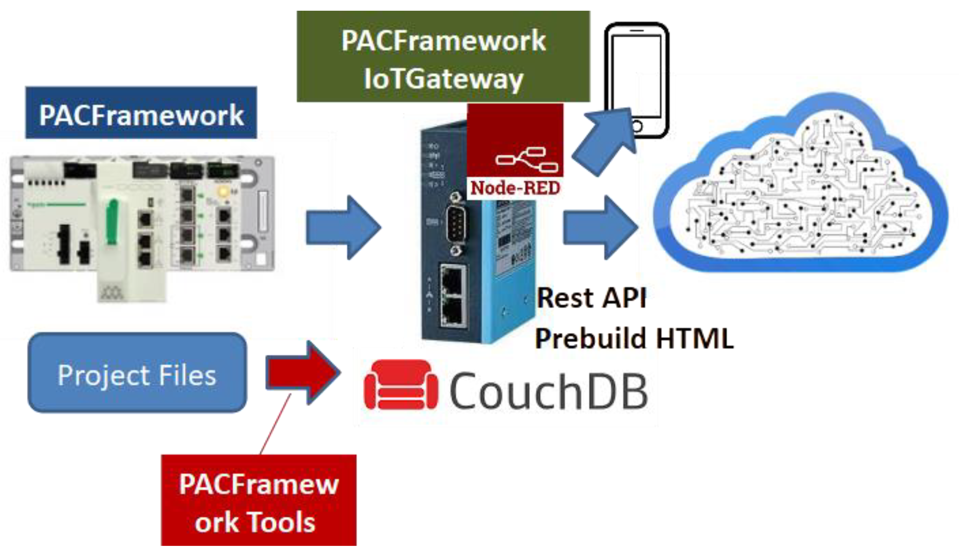
PFwIoTGateway
PACFramework IoTGateway (PFwIoTGateway) is an execution system project developed in the Node-RED environment. It is designed to operate in conjunction with PLCs that use PFw.
The core functions of PFwIoTGateway include:
- Providing a web-based human–machine interface (HMI) for commissioning and tuning control systems implemented with PFw
- Performing IoT gateway tasks, including data collection, processing, local storage, and interaction with cloud applications and storage systems
PFwIoTGateway can run on any hardware platform that supports Node-RED deployment. The project was originally created as a prototype for a specific site, but its implementation was halted after the full-scale invasion of Ukraine by the Russian Federation, as the site is currently located in temporarily occupied territory.
The PFwIoTGateway prototype was fully functional. It was automatically deployed from master data, communicated with an S7-1500 PLC via Modbus TCP/IP, supported commissioning through a web console for process variables (LVL1) and actuators (LVL2), and stored process history locally.
At the time, however, the implementation was relatively bulky and relied on less convenient tools for graphical interface development (native HTML). As a result, it was decided not to continue developing that version. Instead, subject to funding, a new implementation will be developed based on the experience gained.
Figure 2.
PFwIoTGateway Concept.
PFw2 Infrastructure
In the next version of PFw, the framework will be treated as a comprehensive solution that incorporates the functionality of both PFwTools and PFwIoTGateway (see Figure 3). While the framework will still be usable independently of these utilities, its architecture will be designed with their integration in mind.
Although it is still too early to discuss the details of the second version, since development has only just begun, the first iteration is expected to introduce the following changes (highlighted in yellow in Figure 3):
- Master Data (DB) is planned to become part of a composite digital twin of the system, which will eventually serve as a component of the DTw PFw Platform. Import and export via JSON will continue to be supported for offline use.
- Excel or Google Sheets will no longer be considered Master Data, but instead one of several possible Master Data Editors. Reverse synchronization from Master Data to Excel is planned.
- Import/export integration with Eplan Electric (or other CAD systems) into Master Data is also planned.
- The structure of Master Data will be redefined to meet the needs of the new version.
- The DTw PFw Platform is intended to serve as the primary platform for PFwIoTGateway.
- PFwTools in their current form will no longer be developed. Instead, a new set of Node-RED–based services will be created to simplify maintenance and customization.
- PFwTools will include a graphical interface via a dedicated user dashboard.
3. Core Technologies Behind the Framework
At one point, we were offered a project to develop software for a sugar syrup evaporation subsystem at a sugar processing plant. Although the production process was mostly continuous, the control object in this case exhibited characteristics typical of a batch system. Therefore, we proposed using the terminology and approaches of the ISA-88 standard, which had already been implemented in PFw at the equipment phase control level.
The client was skeptical of this suggestion and proposed that we instead follow the approach of another company’s project, which had previously yielded successful results. After reviewing that project, I concluded that it was, in fact, a typical implementation of ISA-88. This situation once again demonstrated that developers often copy best practices from others without understanding their underlying principles or origins.
As a result of such blind replication, a “broken telephone” effect occurs: many concepts remain unclear or are misinterpreted, and portions that were not implemented become unavailable for reuse.
There is a noticeable lack of awareness in Ukraine about international standards and globally recognized best practices. For this reason, we are making significant efforts to promote them [11]. The PFw documentation includes a dedicated section outlining the technologies that form the foundation of the framework, so that developers can either extend PFw or apply similar practices with a proper understanding of their source. The following is a brief overview.
PFw is based on the following key concepts:
- Equipment object model as defined by ISA-88 (IEC 61512), ISA-95 (IEC 62264), and ISA-106
- State-based control, including state machines and operating modes, according to ISA-88
- Alarm state machine as defined by ISA-18.2 (IEC 62682)
- Visualization based on ISA-101 guidelines
- Built-in simulation models within the PLC
PFwIoTGateway additionally builds upon:
- Standardized industrial network protocols
- IoT protocols such as MQTT and REST API
- The Node-RED environment
Standards
A few words about the standards on which PFw concepts are based.
ISA-88 (IEC 61512) is a standard developed for structuring, modeling, and automating batch processes in industrial automation. It defines an object-oriented equipment model, recipe structure, and control procedures, which simplifies the design, implementation, and maintenance of control systems for batch production with flexible recipes not just in terms of parameters but also in sequencing. Ukrainian-speaking readers can explore the principles of this standard in the training materials [12]. The most valuable part for understanding is Part 1 of the ISA-88 standard.
ISA-106 defines the automation of procedures in continuous processes. It provides models and methods for representing and implementing procedural control to improve consistency, safety, and operational efficiency in continuous manufacturing. This standard is particularly interesting because it shows how to automate procedures that are often performed manually. In my opinion, the standard contains several problematic aspects, which I discussed in [13].
ISA-95 (IEC 62264) defines the integration of manufacturing operations management (MES) systems with enterprise business systems (ERP) for discrete, batch, and continuous production. It introduces data models, functions, and interfaces that enable standardized data exchange between enterprise and production levels. Although it focuses on integration, it also introduces a consistent vocabulary and helps structure one’s understanding of manufacturing. Ukrainian-speaking readers can learn more about this standard in the training materials [14]. ISA-95 is valuable for PLC and SCADA/HMI automation because it presents a holistic view of an integrated control and management systems. While the approaches to integrated systems are being reimagined in the Industry 4.0/5.0 era, the hierarchical control model for enterprises remains relevant, albeit with some adaptations.
ISA-18.2 (IEC 62682) defines alarm management in industrial automation systems. It describes processes for designing, implementing, and maintaining alarm systems to ensure timely operator notification and support safe and efficient plant operations. This and other standards related to SCADA/HMI are covered in the handbook [15] and its GitHub version [16]. Additional discussion of these standards can be found in [17] and [18].
Equipment Concept
According to the ISA-88 (IEC 61512) and ISA-95 (IEC 62264) standards, during the design, development, and operation of software for manufacturing and process control systems, each automation object is treated as a distinct entity. From a control perspective, an equipment hierarchy is defined, within which each object has its own role and interacts with other objects.
In addition to equipment, the ISA-95 standard also identifies other enterprise resources such as materials, personnel, and their groupings in the form of process and product segments, as well as assets. However, given that PFw focuses on the L1 and L2 automation levels, these resources are not currently considered within the PFw context.
At the control system level (DCS/SCADA), according to ISA-88, all entities are clearly separated into “process” (how to produce the product) and “equipment” (where to produce the product). Process modeling and automation are especially relevant for production with variable recipes, which is exactly what ISA-88 was designed for. On the other hand, equipment automation applies to all types of production, including continuous processes with fixed recipes.
In all the standards mentioned, equipment aggregates functions and their relationships into more general entities that are perceived as a whole. Familiar terms used by automation engineers, such as “control device,” “control loop,” and “actuator,” become parts of the overall equipment structure.
Let’s consider an example of how a basic on/off valve or damper is represented in a classic automation system. Such an object typically includes:
- a control element (the valve or damper itself),
- an actuator with a single pneumatic control signal “OPEN,”
- two end position sensors: “OPEN” and “CLOSED.”
In the P&ID (Process and Instrumentation Diagram), each of these parts is usually marked with a separate symbol (see Figure 4), corresponding to a specific automation component.
In addition to its physical components, an on/off valve is also associated with a range of functions that are often not shown on P&ID diagrams but must be implemented in the PLC and SCADA/HMI algorithms. These functions include:
- Basic control and monitoring functions, such as executing control commands according to a defined logic
- HMI interaction functions, including manual/automatic mode switching and manual control capability
- Alarm signaling functions, such as indicating a “failed to close” condition
All of these functions must be implemented in both the PLC and SCADA/HMI programs, which requires the presence of appropriate variables, tags, or functions. In a traditional approach, these elements are often represented as separate and disconnected variables and functions, rather than being grouped into a single logical entity.
From an operational perspective, a valve is perceived not as a collection of separate functions but in terms of its states. These may include functional states (such as “open” or “closed”), operating modes (“manual” or “automatic”), or alarm states (“failed to open”). These concepts apply to the valve as a whole, not to its individual components or functions. On HMI displays, such automation devices are usually shown as grouped graphical elements, and the animations rely on all tags related to valve operation.
Engineers who are not directly involved in automation perceive valves in a similar way. They also operate in terms of states, not in terms of individual functions or instrumentation. As a result, they are usually not concerned with the separate status of end position sensors; sometimes these sensors are omitted entirely or only one is installed.
This state-based perception of a valve by operations personnel is both natural and intuitive. However, the traditional loop-based approach to control system programming often contradicts this perception. In that structure, all functions are implemented as a list of variables (tags) that are evaluated or modified across different parts of the program.
For example, the control logic for the valve might be implemented in the process control loop, while alarm signaling is handled in a separate alarm and interlock loop. This kind of “scattering” of functionality throughout the code makes it bulky and significantly harder to read and maintain.
Here are several examples of tasks that require cross-functional interaction:
- Blocking a valve if one of the sensors fails
- Blocking a valve if it fails to open
- Temporarily allowing operation without one of the sensors
Using software objects of type “valve” for the example above allows encapsulation of all logic related to that object into a single entity. In this case, interaction with the object from outside components occurs directly through the object itself, rather than by manipulating individual tags or functions associated with it.
For many control system engineers, using an object-oriented approach has become standard practice. However, not everyone applies it, and a partially object-oriented approach is still common. This is often due to the lack of a clear methodology for developing control software. The ISA-88 (IEC 61512) standard provides guidelines for identifying and working with equipment objects, though it does not impose strict constraints. Specifically, it suggests that:
- Equipment exists as a distinct entity in the control system, with its own attributes
- Equipment has an assigned role that determines which functions it is responsible for
- Equipment forms a hierarchy, where its position affects how it interacts with other control elements
Thus, in addition to a set of functions and associated variables implemented in PLC or SCADA/HMI programs, there are separate entities called equipment that can include other objects (smaller equipment parts) and functions. In this report, the term equipment refers to these specialized control system objects that represent the state of their physical counterparts. The functions performed by equipment will be referred to as functional elements.
Other control system components interact with equipment via its state variables and commands.
State Based Control
State
A state is a general property that reflects the current condition or situation of an object. Since equipment includes certain functional elements, its state depends on the states of these elements, as well as on its own previous state. According to the principle of emergence, the state of a system is not simply the sum of the states of its components. However, for the sake of simplicity, we will assume this to be the case in further discussion.
Thus, the state of a piece of equipment can be assessed through its functional elements, for example, in terms of the current operation, active alarms, maintenance status, or control source. In this context, the “generalized state” refers to the combination of all functional element states into a single whole. Depending on the equipment’s state, control signals and execution algorithms may change.
To illustrate, let us consider the previously mentioned valve. Its state can be analyzed based on the states of its functional elements:
- Operational function (control/position monitoring): OPEN, CLOSED, OPENING, CLOSING, UNDEFINED (e.g., both end switches activated simultaneously), and so on.
- Alarm function: NO ALARMS, FAILED TO OPEN, FAILED TO CLOSE, UNEXPECTED POSITION, etc. Each of these alarms also has its own state: INACTIVE, ACTIVE UNACKNOWLEDGED, ACTIVE ACKNOWLEDGED, and so on. The overall alarm state of the valve is determined as an aggregation of the individual alarm states.
- Operating mode: AUTOMATIC (controlled by system logic), MANUAL (operator control), LOCAL (controlled by local switches), or LOCKED (control functions disabled).
- Simulation mode (for commissioning): NOT SIMUALTED (input values are read from physical inputs and outputs are written) and SIMULATED (sensor values are generated by the simulation algorithm, and output signals are not physically written).
- Maintenance function: ON REPAIR, OPERATING, along with parameters such as the time of the last service and the number of switch operations.
The list of functional elements and their states is determined by the control and monitoring requirements of the equipment and is not limited by the standard. Since a piece of equipment may consist of multiple devices, the total number of possible states can be much larger, as it spans multiple components.
For example, in equipment such as a pump with a VFD, the overall state is defined as a combined set of states from two objects: the motor and the VFD. Additionally, from an operational perspective, beyond discrete states (e.g., ON, OFF), analog values such as current frequency (speed), current, voltage, and others are also considered. At the same time, sets of discrete states of functions, such as “running at minimum frequency” or “at maximum”, can be formed based on analog values.
Thus, equipment monitoring is carried out via corresponding state variables, which must be implemented in the PLC program, SCADA/HMI, or another intelligent device. For discrete functional states, these are typically status bits with TRUE/FALSE values or combinations thereof.
bit statuses = discrete states or a combination of it
The combined states of functional objects represent a concatenation of their respective statuses. In this case, all functional object states can be grouped into an ordered set of bits that forms a status word for the entire piece of equipment.
status word = set of bit statuses of equipment element functions
By using the status word, other parts of the system can analyze the state of equipment as a single whole through its bitwise representation. This allows monitoring of both the individual state of a specific functional element by referencing the corresponding bit, and bitwise processing using masks.
For example, the status word for a valve might look like the one shown in Table 1. Certain state bits may be mutually exclusive, such as the bits for “OPEN” and “CLOSED.” If both of these bits are zero, it may indicate an intermediate state. Similarly, if bits 5 through 8 are all zero, this may signal an “UNDEFINED” state.
The conditions regard not only the equipment but also the procedures in procedural management.
State Machines
When writing a program to implement an equipment object, it is necessary to ensure that its state changes based on the states of its functional elements and other objects it contains. These states should transition according to defined conditions. Such behavior can be described using a verbal algorithm, for example:
if the valve is in the “CLOSED” state and the “OPEN” command has arrived,
go to the “OPEN” state
For the alarm function, this might look like this:
if the valve is in the “OPEN” state and the end sensor does not work
position and opening time is greater than the maximum, then go to the state “NOT OPENED”
It should be noted that in this example, the state control algorithm for the alarm signaling function relies on the states of the operational function. This means that the states of different functional elements within a piece of equipment are interrelated. This interdependency is one of the reasons why it is logical to group functions within the equipment object.
An algorithm that defines the rules for transitioning between states for a given function is known as a state machine. A more convenient way to represent a state machine is through a graphical state diagram. In such diagrams, the states are represented as nodes, and the transitions, along with the conditions under which they occur, are shown as edges.
State machines are a classical mechanism for formalization and modeling, widely used across various domains, including industrial automation. For example, Figure 5 shows a simplified state diagram of a classical alarm state machine as described in the IEC 62682 standard. The alarm states are represented as circles with labels that describe the combinations of alarm status and acknowledgment. In this case, the alarm state is a generalized indicator that depends on the current status values and the previous state. The arrows in Figure 5 represent transitions between states, with conditions specified for each transition.
Although the alarm system has only four states, the diagram appears fairly simple. However, the ISA-18.2 (IEC 62682) standard defines three additional shelving states, which can be entered from any other state.
Now let’s consider a state diagram for the operational function of a valve. In the simplest case, the valve has two states - “OPEN” and “CLOSED”. Depending on the availability of limit switches, the valve can be described using different state machines, examples of which are shown in Figure 6. The labels on the arrows indicate the conditions for triggering transitions.
At first glance, each of these options seems self-sufficient. However, each comes with a number of drawbacks.
In the version with two limit switches, a failure of one sensor may lead to a situation where neither is active - or both are active simultaneously. This scenario is not accounted for in the state machine. A similar issue can occur in the second variant if the position sensor fails. In the third variant, there is no state monitoring at all. In this case, proper control logic might require considering the movement time to avoid issues such as water hammer. None of the presented options include alarm generation based on states, as there is no alarm state machine to rely on.
Clearly, in cases involving limit switches, it is necessary to incorporate control commands as conditions for state transitions. These commands refer to the instructions sent to the equipment object—not directly to the hardware components like the actuator.
To simplify the construction of the alarm state machine, it is also advisable to introduce additional transitional states such as OPENING and CLOSING. Furthermore, an UNDEFINED state should be provided for situations where the valve position cannot be determined. This state can be used as the initial state during control program initialization or triggered in case of sensor faults (for example, when both position sensors are active).
Using this approach, the state diagram of the operational functional element would look like the one shown in Figure 7.
The previous example focused on determining and managing states, but it did not address actions on the physical device. Each state can include certain control actions. For example, in the OPENING state, a digital output of the PLC can be activated to open the valve. Additionally, a timer can be started in this state to track how long it persists - this duration can then be used for alarm handling.
This state-based action mechanism simplifies control logic, as in a given state of a control object, only a subset of sensors is typically relevant, rather than all available signals.
Using the state diagram of the valve’s operational functional element, a control algorithm can be described that also leverages other state machines. Other functional elements of the same valve can reference this state machine to build their own logic.
As an example, consider the state machine for the alarm functional element NOT CLOSED. For simplicity, we’ll only consider the alarm activity status without confirmation or shelving (see Figure 5). As shown in the diagram (Figure 8), the alarm is triggered when the valve is in the CLOSING operational state and the time spent in that state exceeds the maximum allowed.
As shown, the state machines of alarm-related functional elements are closely tied to operational state machines. In some cases, these state machines are visualized together on a single diagram. However, it is important to understand that combining two state machines, such as those from Figure 7 and Figure 8, may result in multiple states being active at the same time. For example, both “CLOSING” and “NOT CLOSED” could be active simultaneously, which might not be immediately apparent from the graphical representation.
At the same time, there are cases where multiple state machines can be merged into one - for example, this is often done for VFDs. In any case, the software implementation can be based on operational states, within which the state transitions of other functional elements are handled.
In the valve example, the equipment can be described using several interrelated state machines:
- an operational state machine;
- four alarm-related machines: “NOT OPENED”, “NOT CLOSED”, “POSITION MISMATCH”, and “SENSOR ERROR”;
- a lockout state machine;
- an operating mode machine;
- a simulation machine.
Modes
According to the ISA-88 standard, a mode defines the manner in which operational functions are controlled. Essentially, modes are distinct states that influence how equipment functions are executed and, in some cases, affect the behavior of their state machines.
For equipment, ISA-88 recommends using two modes: MANUAL and AUTOMATIC. In MANUAL mode, the operational state of the equipment is determined by commands from the HMI, whereas in AUTOMATIC mode, it is driven by control algorithms.
In practice, additional modes may be required. For example, for the valve described earlier, Figure 9 presents a state diagram that includes extra modes such as LOCAL MANUAL and LOCKED. In LOCAL MANUAL mode, the valve is controlled from a local bypass panel located near the valve. In LOCKED mode, the valve continuously receives a CLOSE command.
In the state machine shown in Figure 9, control commands may originate from different sources. However, in certain cases, the state machines of some functions may vary depending on the current mode of the equipment. For instance, the diagram in Figure 7 does not consider the OPEN and CLOSE commands in the LOCAL MANUAL mode, since those commands are not monitored by the system. In such cases, it is advisable to define a separate state machine for that mode.
The examples above illustrate mutually exclusive states. For example, the states OPENING and CLOSING from Figure 7 can never be active simultaneously. However, with the four-mode example, situations may not be as clear-cut. For instance, MANUAL (from HMI) and LOCAL MANUAL (from local bypass panel) modes could occur at the same time. In such cases, it is essential to clearly define priority rules for managing states in the program. Typically, LOCAL MANUAL has higher priority, as commands from the controller are ignored in this mode.
It is also worth noting that defining a state machine helps to identify ambiguities and contradictions in the technical specification more easily. This is another reason why formalization, especially in the form of diagrams, is essential.
Transition Conditions and Commands
As mentioned earlier, state machines are defined by states and transitions between them, each governed by specific conditions. Transition conditions may include control commands issued by automation logic (or HMI), or state changes detected by the control system, usually via sensors. For example, in Figure 7, the transition from the OPEN state to the CLOSING state is triggered by a CLOSE command from the control system, while the transition from CLOSING to CLOSED occurs based on a signal from a limit switch. It’s important to note that the limit switch, which is a component of the valve, is also an equipment object with its own states. For instance, it may have a FAULT state, which can affect the states or even the operating modes of higher-level equipment, such as the valve itself.
From the perspective of equipment as a virtual representation of a physical entity, any action directed at it, or verification of its internal state (such as a control command or state monitoring), can serve as a transition condition. The implementation of a state machine precisely facilitates changing the equipment to the required state.
Controlled transitions are triggered by commands that may originate from different sources: control algorithms, HMI systems, higher-level systems, and so on. In some cases, these commands are processed using different algorithms, and this should be clearly reflected in the state diagram. Commands may be implemented as bit signals (e.g., OPEN, CLOSE) or as a numerical command word, where each command corresponds to a specific numeric value. Since equipment typically processes only one command at a time, a single variable (command word) is usually sufficient to convey all possible control commands. The command handler ignores any commands that are not permitted in the current state or operating mode.
Important Note:State machines should be used with caution. It is essential to implement fallback mechanisms for scenarios where transition conditions fail to trigger - otherwise, the state may get “stuck.” To prevent this, it is advisable to include, for instance, a forced initialization command for the state machine. Additionally, critical blocking conditions (such as safety interlocks) should be implemented in a separate part of the program with the highest execution priority, ideally at the end of the PLC task cycle, and without relying on a state machine.
For safety-critical applications, these functions must be implemented within dedicated safety systems. PAC Framework is not intended for this purpose!
Propagation of Modes and States Between Objects
The modes and states defined within the control system for different objects typically interact with each other. For example, the overall system may have defined modes such as MANUAL, AUTOMATIC, and COMMISSIONING. Switching to the COMMISSIONING mode may alter the priority between the MANUAL and AUTOMATIC modes, as well as the BLOCKED/UNBLOCKED states.
In hierarchical and distributed control systems, individual entities (such as equipment or procedures) are often interdependent, resulting in mode and state relationships between them. In many cases, these dependencies can also be represented through state machines. For instance, switching the entire system to manual mode may automatically switch all actuators within the system to manual mode. Similarly, placing the main control procedure into a PAUSE state may result in all currently executing phases entering the PAUSE state as well.
Equipment Hierarchy
Definition of Equipment Hierarchy
According to the ISA-88 (IEC 61512) and ISA-95 (IEC 62264) standards, all equipment at a manufacturing site occupies a specific level within a hierarchy, depending on its role in the production chain and business processes. When designing control systems using these approaches, it is necessary to decompose equipment according to its functional role. This means that all existing production (and sometimes non-production) equipment must either be grouped into specific entities or, conversely, divided into smaller objects, each fulfilling a defined role and described by its own set of state machines.
Depending on the type of production process (continuous, batch, or discrete), the principles for defining equipment objects may vary. In any case, clear rules for equipment decomposition must be established at the design stage, as poorly considered decisions can complicate future development and maintenance.
Decomposition criteria may be formulated from different perspectives depending on specific control objectives. Some general guidelines include:
- the object has a unique set of operational states;
- the object has performance indicators (KPIs);
- the object has its own set of operating modes;
- the object has a defined set of alarms;
- the object is identified as a technological unit that performs one or more process operations.
If an equipment object consists of a set of other equipment, each element within it will have its own functional states, operating modes, and alarm states, which together form the corresponding state set for the higher-level object.
For example, a pasteurization-cooling unit (PCU) may include a pasteurizer, separator, and homogenizer. From the perspective of the process control system, these three units perform specific functions within the technological process. However, from the perspective of Manufacturing Operation Management (MOM), they are viewed as a single object known as the PCU, which produces a product with defined characteristics. At the same time, the homogenizer may be a standalone automated machine, consisting of its own equipment set with individual states and modes.
The hierarchy is built according to the principle of subordination. That is, it defines how higher-level objects control or monitor lower-level ones. In the case of a valve, for example (see Figure 10), the valve object includes three lower-level equipment objects: two limit switches (“OPEN” and “CLOSED”) and an opening solenoid. When developing the control software, a higher-level equipment object such as a heating unit interacts directly with the valves via commands and status feedback, rather than with their individual limit switches and solenoids.
This approach allows the control system developer to focus on implementing equipment functionality by first defining the state machines and their interactions at different levels of the hierarchy.
According to this structure, the implementation of functions for the lowest-level equipment may involve direct interaction with sensors and actuators, including:
- Processing of input and output values: scaling, filtering, inversion, etc.
- Ability to manually override sensor values (forcing)
- Operation in simulation mode
- Alarm handling in accordance with IEC 62682, including:
- Threshold-based response for analog signals
- Consideration of delay and hysteresis
- Generation of system bits for fault or warning conditions
- Configuration capabilities:
- Setting threshold values and alarm parameters;
- Temporarily taking alarms out of service;
- Configuring scaling and filtering parameters.
Thus, the role-based hierarchy enables interaction between equipment using state machines without requiring knowledge of their internal structure. In addition to clear interactions via commands and status feedback, the hierarchical approach provides several less obvious but important advantages. For instance, in the case of an equipment object like a valve, it allows:
- Considering the state of lower-level objects (normal/alarm/validity) and diagnostic information in the control logic. For example, if a limit switch is in an INVALID state (due to I/O module failure), the valve can automatically switch to a LOCKED mode.
- Simulating the operation of subordinate sensors by managing their states using a simulation algorithm (e.g., for testing or operator training).
- Controlling the INVALID state of subordinate sensors with logic - for example, if both limit switches simultaneously indicate activation.
Given the interaction logic within the hierarchy, switching higher-level equipment (such as a pasteurization-cooling unit) to manual mode often automatically sets manual mode for all subordinate elements such as actuators. In other words, the hierarchy enables the propagation of modes from higher-level equipment to lower levels - or vice versa. Similarly, state propagation can also occur.
Standard IEC 61512 only mentions the possibility of such propagation, but this already implies the need to define specific implementation rules during the design stage. An example of state propagation is the transmission of alarm states from lower-level equipment up the hierarchy. This means that all alarms are monitored at a higher equipment level according to the categories defined in IEC 62682.
The equipment role hierarchy defined in ISA-88 (IEC 61512) and ISA-95 (IEC 62264) is illustrated in Figure 11. According to this hierarchy, each equipment entity performs a defined role in the production process. When integrating higher-level systems with industrial automation systems, control and monitoring are performed through equipment states and commands.
Higher-level control entities (enterprise, site, area) are viewed from the perspective of organizational management and fall within the domain of ERP-level systems. In this context, the term “equipment” is best understood as “production facilities”. Areas produce a defined set of products, while production operations are carried out at work centers - equipment that produces intermediate products.
Work centers are the primary means of managing production operations. Their activities are scheduled, dispatched, and monitored by MOM (Manufacturing Operation Management) systems. Within the work centers, the control of operation execution depends significantly on the production type. For batch production, these processes are governed by the ISA-88 (IEC 61512) standard, which also defines the implementation of lower-level equipment, starting from the work center itself.
It is important to emphasize that this equipment model is based on functional roles. In this hierarchy, a pump is understood as any equipment that performs a pumping function at a specific location within the process. It refers to equipment that has a designated symbol on the P&ID. If the specific pump is replaced with a unit from a different manufacturer that performs the same role, it is still considered the same pump within this model.
To account for specific equipment instances (including serial numbers), the ISA-95 (IEC 62264) standard defines a separate Asset Model. PFw currently does not implement the asset model, as it requires significant memory resources on the device. However, in the context of distributed control based on the framework, a separate object can be created to represent an asset if needed.
Equipment Hierarchy in ISA-88 (IEC 61512)
According to the ISA-88 standard, the highest level of equipment within an industrial control system is the Process Cell (see Figure 11). The Process Cell, as defined in ISA-88, corresponds to the Work Center defined in IEC 62264 and ISA-95. While a Work Center may be used across various production types, the Process Cell is defined strictly in the context of batch processes, which is a distinguishing feature of ISA-88.
A Process Cell is a logical grouping of equipment required to produce one or more batches of (semi-)product. It defines the scope of logical control over a specific set of process equipment within a production area.
The existence of a Process Cell enables production planning at this level and supports the development of a comprehensive control strategy for the entire process. A Process Cell includes Units, Equipment Modules, and Control Modules, all of which are necessary to produce one or more batches.
The key idea of ISA-88 is that a recipe is created for each Process Cell, specifying what and how is to be produced using available equipment. The recipe is created by process engineers and includes the Procedure for producing the (semi-)product, along with additional parameters. The Process Cell Procedure is further divided into Unit Procedures, which can in turn be split into Phases, forming what can be considered a complete “production program” for a given batch.
A Batch Unit is equipment in which one or more major processing activities can be carried out with an entire batch of material or a portion of it. As an independent grouping, a Unit combines all the necessary processing and control equipment required to execute these operations. It consists of Equipment Modules and Control Modules, which may either be permanently associated with the Unit or temporarily allocated to it for specific tasks.
An Equipment Module is capable of performing a defined set of specific processing operations, such as dosing or weighing. It includes all the physical equipment and control elements needed to carry out those operations. From the perspective of batch control, the Equipment Module executes the minimal process action defined in a recipe called a Phase.
A Control Module (CM) typically consists of sensors, actuators, other control modules, and associated process equipment that operate as a single control unit. A Control Module can be composed of other control modules. For example, a control module for a material feed manifold might include several valve control modules (each with an actuator and sensors). Control Modules may be part of an Equipment Module or directly assigned to a Unit or Process Cell. In the physical model, a Control Module cannot simultaneously belong directly to both a Unit and an Equipment Module.
From the ISA-88 perspective, Control Modules are responsible for executing Basic Control functions.
IoT Technologies
PFwIoTGateway collects data from PLCs using industrial protocols and facilitates communication with external systems via IoT and IT protocols. Its implementation is based on the LoCode tool Node-RED [20], which enables the development of IoT (and other) applications through a graphical, web-based editor. Despite its power and relative simplicity, this tool has not yet gained widespread adoption in the field of industrial automation in Ukraine.
To interface with other systems, the following IoT protocols are used: MQTT, WebSocket, and REST API. In my view, a modern industrial automation programmer should be proficient in these protocols. For this reason, I have created and published relevant courses, which are freely available on GitHub [21].
Overview of Other Technologies Used
PFw incorporates many additional practices that are commonly accepted by engineers and often considered standard techniques. Therefore, they are only briefly listed here.
TimersHardware timers, which remain a limited resource in PLCs, are still used in some devices. However, current best practices recommend using IEC-standard timers (TON, TOF, TP). Many developers, seeking to optimize resource usage and gain more flexible control (e.g., the ability to freeze values), implement custom software timers.
Two main approaches can be identified in this practice:
- Using incremental counter variables updated by a periodic pulse bit;
- Using a variable that increases based on the time difference between function calls.
In the early implementations of PFw, the first approach was used. However, it later presented issues when the function was called less frequently than the pulse bit’s cycle. Therefore, the second method is now preferred, as it is more reliable and flexible.
Hardware Abstraction
The concept of hardware abstraction involves creating an intermediate layer upon which the rest of the code is built. This approach is widely used across various environments, including Java, .NET, and many other platforms. Even operating systems have dedicated subsystems that enable them to function across different hardware platforms.
In PLC programming, this approach is applied for indirect addressing of inputs, providing a unified interface for functions (FCs) and function blocks (FBs), and creating FCs/FBs specifically for abstraction purposes. This allows libraries to be reused across different PLCs without changing the core control logic.
Working with Platform Constraints
During development, engineers often face various platform limitations. For PLCs, these may include constraints on memory, the number of variables, processing speed, functionality, or network connections. For SCADA/HMI systems, limitations typically involve the number of simultaneously displayed tags, available screens and variables, or supported protocols.
In such cases, at least three strategies can be distinguished:
- Avoiding constraints by changing the system architecture or selecting a different platform;
- Accepting the constraints and adapting the architecture accordingly;
- Offloading part of the functionality to external services or devices.
When applying the second strategy, architectural adaptation may lead to a reduction in functionality. However, this is not necessarily the case by using certain techniques, it is possible to retain the required functionality. Some of these techniques include:
- Using indexed arrays and buffers to exchange large volumes of data;
- Implementing universal FCs/FBs with parameterization;
- Distributing processing across cycles (using a scheduler);
- Bit-packing into words to optimize data transmission.
Further details on overcoming such limitations can be found in [10].
Built-In PLC Simulation Models
Simulation modeling has long been used for code debugging and personnel training. There are several approaches to this, including the use of external simulation tools or embedding the model directly within the PLC program. PFw currently employs the second approach, utilizing built-in simulation models within the PLC itself. A detailed description of this method is provided in the corresponding section of the manual [22], which is also available in the GitHub version [23].
4. Technological Solutions in PFw
This section outlines the technological solutions adopted in PFw. A detailed description of each object—including variable structures, FC/FB interfaces, testing procedures, implementation examples, and library elements is available in the GitHub repository [1] in both Ukrainian and English. Here, we focus solely on an overview of the key solutions.
First and foremost, it is important to note that PFw does not restrict PLC or SCADA/HMI developers in implementing control algorithms. Instead, the framework provides a ready-made mechanism for implementing abstractions, enabling developers to focus solely on designing the control logic of the technological process. The developer can write a program that coordinates the invocation of existing PFw software components, without spending time on implementing basic functions.
Equipment Hierarchy
The ISA-88 and ISA-106 standards are both based on the equipment concept, although they consider it from slightly different perspectives. The lower equipment levels according to these standards are shown in Figure 12 (left). PFw adopts the concept defined in ISA-88, and its implementation fully aligns with the standard’s requirements.
In addition to the equipment concept, PFw also incorporates other entities, such as procedural control. More details about this can be found in the GitHub repository; this report does not cover that topic.The higher equipment levels in PFw are used in the same sense as defined by ISA-88. Particular attention is paid to the lowest level, namely the Control Module, which serves as the foundation of PFw. It will be described in more detail below.
CM Hierarchy
ISA-88 allows control modules to be included within other control modules. In the PFw framework, regardless of the type of process controlled by the industrial automation system, three typical levels of equipment objects are defined at the Control Module (CM) level (see Figure 12, right )
1. LVL0 (Channels) – PLC channels, for diagnostics, binding logical channels to physical ones, and forcing inputs/outputs:
- CHDI – Digital inputs
- CHDO – Digital outputs
- CHAI – Analog inputs
- CHAO – Analog outputs
- CHCOM – Communication channels
- Additionally, other objects related to channel operations are included here, such as MODULS, used for displaying module states and providing interactive diagnostics (e.g., PLC module mapping).
2. LVL1 (Process Variables) – Process variables for full signal processing, including binding to channels, filtering, scaling, inversion, etc.; for convenient process debugging; for simulation modeling; for process alarming:
- AIVAR – Analog input variables
- AOVAR – Analog output variables
- DIVAR – Digital input variables
- DOVAR – Digital output variables
3. LVL2 (Devices) – Device and actuator level, designed for easier debugging, simulation modeling, process alarming, and statistics collection:
- Actuators (on/off valves, control valves, motors, pumps)
- Control loops and regulation circuits (for feedback control functions)
- Other devices that include multiple process variables and have explicitly defined states
All the elements listed above are considered Control Modules according to ISA-88 and Devices according to ISA-106. For consistency, we use ISA-88 terminology, as it is the currently prevailing standard.
The three-level architecture defines the interaction model between levels as follows:
- All elements, regardless of level, are processed in parallel, there is no nested POU calling; the subordination model is implemented via an Allocation mechanism or conventional programmatic links.
- Level 2 elements (e.g., actuators, controllers) must not interact directly with Level 0 elements (channels).
- Higher-level elements can interact with any lower-level elements except those at Level 0 (as per the previous rule).
- A higher-level element may change the state of a lower-level element: modify its value, switch modes (e.g., forcing, simulation), change alarm settings, etc.
- A Level 1 element (process variable) can allocate a Level 0 element (channel).
- A Level 0 element is aware of who owns it.
- A Level 1 element knows what it owns.
- When elements are implemented across different devices (in distributed systems), the interaction occurs via STATUS–COMMAND pairs (described later). When implemented within the same device, both direct value access and STATUS–COMMAND interaction are allowed.
All levels except LVL0 must interact only with entities defined in PFw; otherwise, platform portability cannot be ensured. For this reason, LVL0 also serves as an abstraction layer from the specific PLC/PAC implementation. Further abstraction is provided through PLCFN.
Typical Modes
For most Control Module (CM) objects, the following modes are used:
- Supervisory/Automatic – for LVL2 objects, indicates whether control is performed by SCADA/HMI or PLC logic.
- Local Manual – for LVL2 objects, indicates that control is performed from a source outside the PLC+SCADA/HMI system.
- Simulation – a mode in which input values are generated by a simulation model algorithm.
- Forcing – a CM mode for LVL0 and LVL1, in which the input or output value is set from SCADA/HMI (similar to supervisory mode for LVL2).
PLC Class and Object
Framework-level abstraction from a specific platform implies that the upper layers of PFw interact only with lower-level objects. Access to I/O is resolved via LVL0 objects, while other framework functionalities are implemented using the PLCCFG variable and PLCFN function block. These serve as the central coordinating modules of controller-level logic (see Figure 12) and are responsible for:
- Executing controller-wide functions, particularly those not related to any specific process area or equipment section;
- Monitoring controller statuses, such as lockouts, forcings, manual modes, first scan, and whether at least one object is in simulation mode - used, for example, to display controller status on HMI;
- Monitoring global alarm statuses (e.g., active alarms, warnings, channel faults, new alarms, unacknowledged alarms);
- Handling general signaling, such as hardware light and sound indicators (buzzers, sirens, etc.) and their acknowledgment;
- Processing PLC-specific alarms (e.g., cycle time overrun);
- Generating interval bit pulses and square waves (meanders);
- Maintaining statistical data (if required);
- Calculating integral metrics, including total runtime since the last or first start, and timestamps of the last stop/start events;
- Formulating general operator messages;
- Receiving and processing broadcast commands for other framework objects.
- The PLCFN function block handles essential general controller operations:
- acknowledges broadcast commands (passes the broadcast command through for one cycle)
- detects the first scan of the task - sets the corresponding bit to 1 for one cycle at the first scan
- generates bit pulses and square waves (see CFG) that can be used within the same task (TASK) where the function is triggered
- maintains general time in milliseconds (rolls over upon reaching the maximum UDINT value)
- tracks the elapsed time since the first controller cycle (in seconds)
- tracks total PLC uptime since startup (in minutes)
- provides astronomical time in BCD format
- indicates the start of the hour and day
- indicates the start of a shift (default: 8-hour shift)
- resets alarm bits and certain status bits collected during the entire cycle from procedural and basic control (see PLC_CFG)
- resets alarm counters and some status words
- displays current cycle time (last task execution time and maximum in milliseconds)
The PLCFN function block can also handle the following general PLC operations:
- generation of additional square waves
- control of general audible alarms
- maintenance of additional general statistics
- monitoring (alarm control) of communication with other PLCs
- monitoring (alarm control) of communication with DIO (distributed I/O)
Note on future use
The PLC abstraction in PFw does not support multitasking mode. This is a significant limitation for applications that explicitly require task separation. Therefore, version 2 introduces two entities:
- TASK, which handles each task and is executed in sequence with all objects associated with it
- PLC, which processes the results of TASKs and communicates with the HMI
Channels (LVL0) and PLC Map
The lowest level of control modules, called channels, provides abstraction from the specific hardware implementation (PLC, distributed I/O, etc.). The implementation of this level depends both on the selected platform and the method of realization.
CM elements of the “channel” type represent arrays of all available controller channels, regardless of their location (local chassis, remote I/O) or actual use in the process. Each array element has a unique number, and binding to the physical channel is hardcoded at the software level.
A CM of the “channel” type performs the following functions:
- binds its internal value to the physical value of a specific channel
- provides higher-level CMs with diagnostic information, at minimum a valid bit, and if possible - the reason for channel failure or malfunction
- includes a value forcing mode:
- forced overrides the input channel value regardless of the physical signal
- forced overrides the output channel value regardless of the variable assigned to it
- indicates the fact of binding to a process variable and its number
Figure 13 and Figure 14 show example display screens implementing these functions on different platforms with varying resource constraints. Such mimics are referred to in the framework as the PLC map. Channels used by the PLC are marked with a “+” symbol. Information for each channel is available by clicking on it. The PLC map provides functions such as showing the bound variable, validity flag, and force commands. In case of a hardware fault, the channel is highlighted in red. For implementations with very limited resources, some functions may be omitted if they significantly complicate the system or consume excessive resources (see example in Figure 14).
When implementing the PLC map, a significant amount of resources is required not only on the PLC side but also on the SCADA/HMI side. For example, the number of tags needed to implement this on a high-channel-count PLC can be extremely large, often making the direct solution unacceptable.To preserve this diagnostic capability while avoiding excessive consumption of SCADA/HMI resources, an intermediate solution is proposed: displaying information grouped by channel sets combined into separate objects - MODULS and SUBMODULS.
Examples of both approaches (without grouping and with grouping) are shown in Figure 15.
Below is one implementation option for working with a group of channels. Implemented functions include:
- continuous monitoring (display) of channel errors (if at least one) at the MODUL level
- selection of a channel group for display (SUBMODULS - a group of 16 channels)
- displaying the status of channels in the selected group according to the channel structure data
- loading any channel from the group into a buffer (see below for buffer details)
- interaction with the channel via the buffer (forcing, value modification)
Note on future use
Even with data exchange implemented via MODULS and SUBMODULS, channels still consume a significant amount of PLC memory resources. As a result, in certain implementations, colleagues completely removed this level from the hierarchy. In PFw2, the channel concept will be fully rethought and redesigned to retain functionality. First prototypes already show positive results, though it is too early to speak of a final implementation. So far, the following has been achieved:
- a significant reduction in the memory required for channel variables
- synchronization of channel buffer loading with the variable bound to the channel
It is also worth considering a mechanism for abandoning LVL0 in favor of direct access to channels or their simple copy. This would eliminate the PLC map but would enable further resource savings and allow PFw to be implemented on small PLCs.
Process Variables (LVL1) and Variable Map
CMs of LVL1 type, called process variables, can be linked to a channel of the same type (e.g. a digital input linked to a digital input process variable) by their index. This makes the binding of a process variable to a channel dynamic, allowing the physical connection of a specific sensor or actuator to be changed in case of partial system failure. Such switching can also be performed programmatically.
Process variables are positioned above channels in the control hierarchy. All diagnostic information is transferred from the channels to the variables. The implementation of this level is independent of the controller’s hardware, as all platform-dependent specifics are handled at the channel level, whose interface is standardized within the framework.
Process variables provide the following functionality:
- binding to a channel by its number and type, with optional dynamic reassignment (configured channel number)
- deactivation from service (alarm suppression and upper-level exclusion)
- monitoring of value validity based on channel faults, out-of-range measurements, etc.
- diagnostic reporting from the linked channel to the upper level
- input/output value processing: scaling (including piecewise linear interpolation if needed), filtering, inversion (for digital variables)
- forcing (manual mode according to ISA-88)
- simulation mode, where for input variables the value is set by upper-level CMs (or an independent program), and for output variables the values are frozen at the output channel
- alarm handling (ISA 18.2): threshold reaction, delay consideration (limits configurable via separate setpoints if needed), hysteresis, generation of a general system alarm/warning bit, one-cycle new alarm flag
- alarm configuration (ISA 18.2): setting alarm values, alarm types (alarm/warning/channel failure), temporary alarm suppression
Examples of process variable diagnostics and configuration on the HMI are shown in Figure 16 and Figure 17.
Screens listing all process variables in the framework are referred to as the variable map.
Variable statuses (alarms, faults, forcing) accompany the display of the variable on all HMI mimic screens.
Figure 18 shows an example of a warning indication for variable PT102 on a panel with limited functionality (Simatic Basic Panel).
The following types of process variables can be distinguished separately:
- network variables - their data source is located on other (networked) nodes, and the address cannot be changed during operation
- calculated (internal) variables - computed based on several other variables or channels
These variables are expected to be implemented as subclasses of AIVAR, AOVAR, DIVAR, and DOVAR. Their processing logic must include special handling based on the class number (CLSID) or the variable ID. For convenience, it is also recommended to reserve a separate identifier (ID) range for such variables.
Note on future use
The current implementation of LVL1 process variables is mature and stable, but questions remain regarding the interaction between LVL0 and LVL1 in the context of different tasks, shared use of the same channel by multiple variables, and linking to network variables. The internal implementation is expected to remain largely unchanged. There is also a need to implement a mechanism for data exchange in IoT systems, as the current functionality is still quite limited.
Control Modules, Loops, Actuators (LVL2)
VL2 CMs represent actuators, controllers, and other elements that implement basic control functions (according to ISA-88 terminology). Each such CM supports bidirectional interaction with process variables, both for reading and writing. This enables, in addition to specific functional logic for a given CM, the following capabilities:
- considering the state of the process variable (normal/alarm/validity) and diagnostic data in the execution logic of the CM
- simulating CM behavior using an internal modeling algorithm (if needed) for:
- advanced model-based process diagnostics
- model-based control
- simulation mode for demonstration, training, or system commissioning
- enabling simulation mode for the CM and all related lower-level CMs
- collecting statistical information (depending on CM type)
Each equipment entity is assigned a function block/function behavior algorithm and a data structure (interface) for communication with other subsystems or objects.
The data structure and function/function block behavior are compatible with ISA-88, i.e., based on state machines, operating modes, and interface definitions specified in the standard.
Figure 19 shows an example of configuration and diagnostics for valve control.
Note on future use
The need for a large number of LVL2 types has led to a certain structural separation in implementation. The current bulky structure has proven to be inconvenient and requires redesign.Moreover, this is one of the most frequently controlled objects from both the IoT and engineering perspectives, so significant changes are expected in its integration at the Digital Twin level.
General Requirements for the Implementation of PACFramework POU, Function and Function Block Interfaces
Structure of Function/Procedure and Function Block Interfaces
Each FC/FB that implements a CM or other object includes internal state data and interface data for interaction with other subsystems (e.g. SCADA/HMI). Interface data for SCADA/HMI is divided into two types:
- Real-Time HMI Data (RT HMI)
- PLC Configuration Data (CFG)
Real-Time HMI data contains all the necessary information for continuous monitoring and control of the CM from SCADA/HMI, including:
- HMI display
- Alarm subsystem integration
- Trend and log data
- Control of the CM state (including configuration control)
PLC Configuration Data (CFG) contains all information required to configure the operation of the CM or other object. Exchange of configuration data with SCADA/HMI occurs during:
- CM parameter setup and verification
- Advanced diagnostics of CM operation
- Use of CM service modes (forcing, simulation, deactivation)
Due to the large volume of configuration data, it is recommended to minimize traffic with other subsystems. This reduces communication load and lowers the cost of SCADA systems that use tag-based licensing.
To achieve this, data exchange between SCADA/HMI and the PLC for configuration purposes can be implemented through an intermediate buffer, shared by all CM instances of the same type (see below).
Separation of data into real-time (HMI) and configuration (CFG) is optional and may require duplication of certain data on the PLC. It may also require strict access separation from SCADA/HMI.It should be noted that although the CFG variable is labeled as “configuration”, it is the primary interface for interaction between program entities within the PLC. The separation between CFG and HMI is needed only for communication with external systems.
ID та CLSID
The configuration data of a CM belonging to a specific group must include both an ID (object identifier within the group) and a CLSID (class identifier of the object). CLSID is used for object classification and customization (see below). ID is a unique identifier of the object within its class.
Principles of Using Buffered Exchange with SCADA/HMI
As previously noted, in addition to real-time data (RT DATA – variable values, statuses), each CM is associated with a large amount of configuration data (CFG DATA) that must also be exchanged with SCADA/HMI, but only when necessary. Most SCADA/HMI systems are licensed based on the number of I/O points.
To reduce the volume of configuration data transferred between SCADA/HMI and the PLC, it is recommended to use a buffer. A separate buffer should be used for each array (set) of similar CMs or other objects. Distinct buffers can be applied for all objects at a given level. For example, separate buffers may be allocated for all channels (LVL0), variables (LVL1), and devices (LVL2).
Each CM has a unique identifier within the set (this can be a combination of ID and CLSID), which allows it to be linked to the buffer (see Figure 20). Upon receiving a READ_CFG command, the CM loads its data into the buffer and associates itself with it (claims or occupies it). Real-time data (RT DATA) is continuously updated in the buffer by the CM logic in the PLC. This may include not only visible RT data, but also additional debug information (e.g., step number, step duration, integral value, etc.). Configuration data is updated in the buffer only upon a read command. This allows the operator to modify values in the buffer and then write them to the CM using a WRITE_CFG command.
The type of configuration variables that need to be stored in the PLC may differ from the type of buffer variable used for transport. The buffer variable typically contains a larger predefined set of fields to allow for the transport of different types of data within the same level (see below).
A particularly practical mechanism is the so-called contextual configuration. In this approach, the configuration (or debugging) window is triggered directly at the location where the CM is displayed on the main mimic screens. This significantly speeds up commissioning, as it eliminates the need to navigate to the process variable maps for actions such as forcing or configuration changes.This mechanism has already been tested in several projects using both SCADA and HMI systems. On the PLC side, no additional functionality is required, since the same buffer mechanism is used.On the SCADA/HMI side, an event must be defined for graphical elements to initiate a buffer read (selection). For SCADA, this can be a context menu item; for HMI, it could be a tap on a designated part of the display element, etc.
Figure 21.
Example of contextual configuration: right-click triggers a pop-up configuration screen (implemented in Citect SCADA).
Figure 21.
Example of contextual configuration: right-click triggers a pop-up configuration screen (implemented in Citect SCADA).
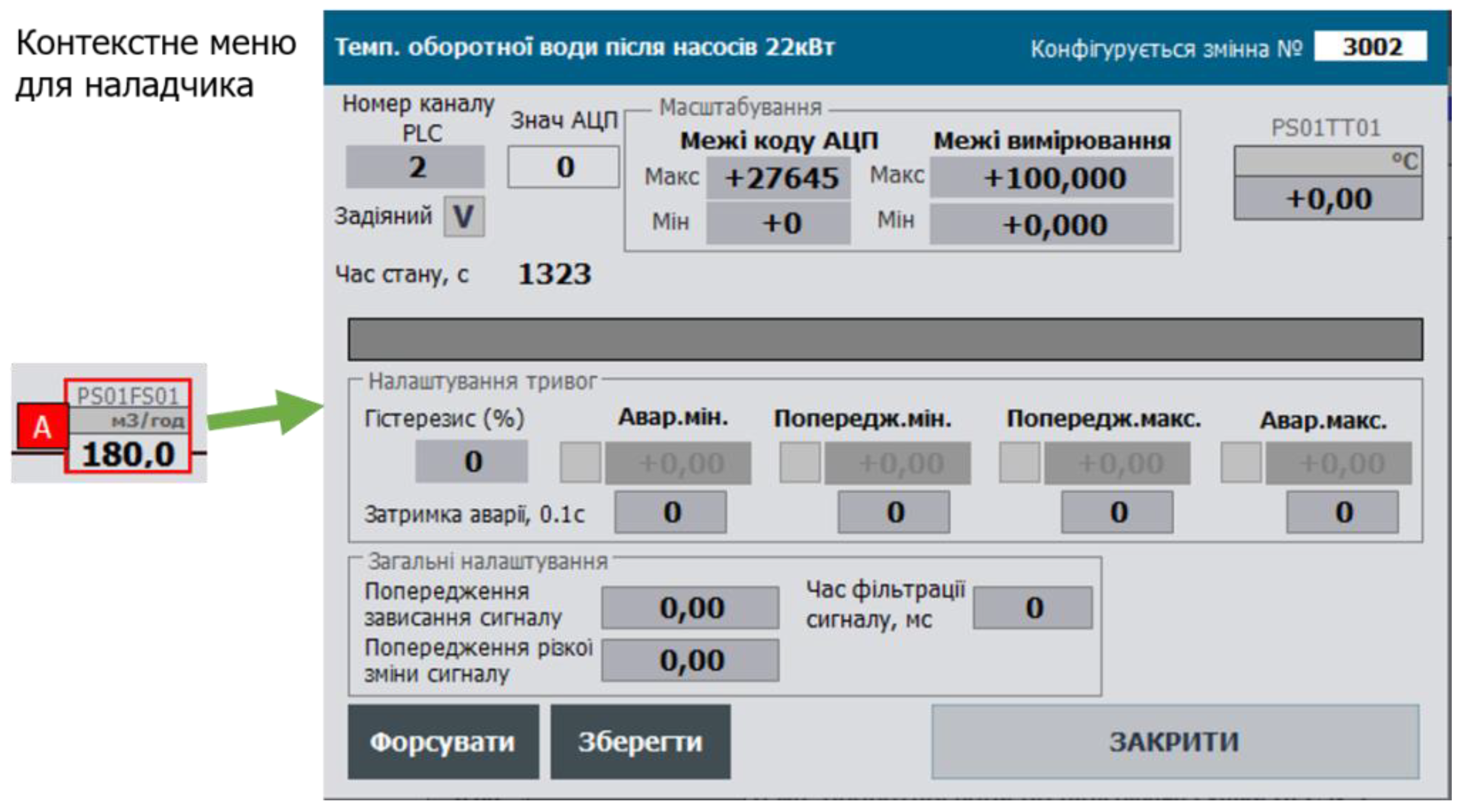
Another possible method of buffer-based configuration is using REQUEST/RESPONSE principles. In this approach, the buffer is not claimed by the object but is passed as a separate variable. When a read request is initiated by a client (SCADA/HMI or another subsystem), the buffer is populated in the same way as in the previously described mechanism. The fully filled structure is placed into the buffer variable, and the object being referenced is determined by its ID and CLSID. After reading, the buffer data is written to the client’s internal variable, completing the session. Even in the case of concurrent access, the client can verify the result of the read request.
The write operation works similarly: the client makes changes in its local buffer variable, which is then copied into the PLC buffer. Unlike the buffer claiming mechanism, variable updates in the client’s buffer require continuous read requests. Furthermore, some SCADA/HMI platforms have limitations regarding reassignment and maintaining the integrity of structured buffer variables, which may prevent use of this approach.
However, this method is more suitable for IIoT solutions based on the framework, as it does not require constant data exchange between the cloud and the field device (PLC, Edge).
Note on future use
Despite significant resource savings, buffer usage comes with certain limitations. The most critical one is the inability to use the same buffer from multiple HMI clients simultaneously — the buffer is “taken over” by the most recent user. Additionally, the current framework lacks a locking mechanism to prevent concurrent access. A potential solution is to allocate multiple buffers, with each client having its own variable.
Another drawback of using buffer-based configuration exchange is the inability to use tabular views for PLC and process variable maps. In practice, there are REQ/RESP-based solutions that can work around this limitation, but they typically require significant scripting effort on the SCADA/HMI side, which is not always feasible.
It is likely that future versions will include recommendations for extending the CM interface to support multiple buffers. Similarly, the REQ/RESP-like exchange mechanism will be reconsidered and redesigned.
State (STA) and Command (CMD) Variables
HMI data typically includes the following 16-bit words:
- STA - status word containing bit sets for all state machines (STATUS) and operating modes (MODES)
- CMD - command word used for controlling the state and modes of the CM, as well as for its configuration; each command is encoded as a unique numerical value across all CM types
The 16-bit word format was chosen for compatibility with most modern IEC 61131-3 platforms. The CMD word must be reset at its destination. This means that, the CM that receives the command is responsible for clearing it (set to 0). An exception is in the case of broadcast commands, in which case a mechanism must be implemented to clear the command after it has been processed by all recipients.
To support hierarchical control, all internal variables representing CMs used inside other CM/EM/UNIT structures are passed using INOUT or by reference, which significantly saves controller memory.
For convenience, configuration data may also include STA and CMD (referred to as STA_CFG and CMD_CFG), which are used only within the PLC program. Thus, the STA sent to the HMI (referred to as STA_HMI) is a copy of the configuration status and is read-only, while the CMD received from the HMI (CMD_HMI) is treated as an operator command and handled accordingly.The STA_CFG and CMD_CFG variables may be implemented as bit structures.
Considering that only a single command, READ_CFG (which also binds the CM to a buffer), is used for CMs at the channel level (LVL0) and process variable level (LVL1), SCADA/HMI tag usage can be optimized. This is achieved by combining the STA and CMD bits into a single variable - STA (STA_HMI). One of the bits in this variable is modified in the HMI to trigger a read command.This configuration has been successfully tested in multiple implementations and has proven to be both functional and efficient.
The framework also supports broadcast commands. All such commands are transmitted via the CMD of the PLC class (see PLC class). These commands are received by all objects of the specified type, not just the one currently bound to the buffer. This may be useful, for example, in the following functions:
- setting default configuration
- enabling/disabling simulation mode
- switching all objects of a class to manual/automatic mode
- ...
Broadcast commands may use the format 4XXX (HEX), i.e., with the 14th bit set. Since each CM of the specified type must process the command, it should only be cleared after a complete PLC cycle has been completed (it is assumed that all CMs are processed within a single cycle).
For implementation details, refer to the repository.
CMD variables for CMs at LVL0 and LVL1 are used exclusively for communication between SCADA/HMI and PLC, or for inter-device communication. CMDs at LVL2 and above are also used within user programs. In this case, multiple sources of commands must be considered: CMD_HMI (SCADA/HMI), CMD_BUF (buffered), and CMD_CFG (program logic). The priority of each command source may depend on the operating mode of the CM or the type of command (e.g., buffer read may have lower priority than a control command, or vice versa).
Note on future use
The presence of STA and CMD is not always required, particularly for some subclasses of channels. To optimize resource usage, these structures will be redesigned.
Data type requirements
For HMI communication, the following data types are recommended: INT/UINT (16), DINT/UDINT (32), REAL (32), ARRAY of INT/DINT/REAL
It is not recommended to use the BOOL memory area or standalone BOOL variables for HMI communication. Instead, use bit fields (but not structures), such as STA bits. In place of the TIME type, use UDINT (milliseconds), or convert the value to REAL. Other data types should be used only as exceptions, if conversion to the recommended types is not feasible. Where possible, 4-byte alignment should be maintained. Following these requirements ensures easier portability of framework elements across different platforms.
Object Classification and Customization Concept
Classes (CLSID)
The separation of functions and their associated data, as well as operational specifics, is based on the concept of classes. Classes enable the implementation of common functionality within a single program element.
When the functions are related to equipment objects, the classes are distributed across levels according to the equipment hierarchy defined in the PAC Framework. Each class is assigned a unique CLSID within the system, which necessitates proper allocation and management.
Parameters
Parameters are configuration variables that define the characteristics of an object and typically change infrequently. They are set during system commissioning and may be modified when operating conditions change (e.g., failures, changes in object properties).
The framework includes mechanisms for the automatic adjustment of certain parameters. In particular, bit-level parameters can be modified when linking multiple objects. For example, actuators connected to position sensors may alter the parameters of those sensors.
Specifically, warning and alarm options for the sensors are forcibly disabled, since such signals are not meaningful in this context.
On the other hand, if a sensor fails, the actuator can be temporarily switched to operate without the sensor by setting a corresponding disabling parameter. When this is done, the actuator automatically enters a “sensorless operation” mode.
State Variables (STA)
State variables are not used to configure the behavior of the object.
Methods for Adapting an Algorithm to Execute Special Actions for Specific Objects (Customization)
To avoid creating multiple separate functions or function blocks that are nearly identical except for a few specific behaviors, it is preferable to implement them within a single program element. Several methods exist for adapting the algorithm to perform special actions:
1. Using CLSID. Assign a different subclass CLSID to special objects, for example by changing the last hexadecimal digit. In this case, the function checks the CLSID and performs specific (custom) actions based on it. This approach is suitable for objects whose algorithm always requires the execution of these special actions. The same program element will thus handle multiple subclasses, executing shared logic while branching conditionally based on the subclass for custom behavior. Example - this code applies to all objects of the class except subclass 16#1011:
//If not a DI with counterIF #DIVARCFG.CLSID <> 16#1011 THEN #VAL := INT_TO_BOOL (#DIVARCFG.VALI);END_IF;
2. Using ID. If only a few objects in the class require custom behavior (a small number), it is not practical to define separate subclasses. In this case, the program element can use the object’s ID to identify and apply custom logic. Example - special behavior for a specific ID:
IF #DIVARCFG.ID = 10001 THEN #VAL := INT_TO_BOOL (#DIVARCFG.VALI);END_IF;
3. Using Parameter Bit (Option) . If the special behavior needs to be enabled or disabled via configuration, bit-level parameters (options) in the object’s settings should be used.Example - inversion is performed only when the inversion option is enabled:
//If inversion parameter is setIF #PRM_INVERSE THEN #DI := NOT #VRAW;ELSE #DI := #VRAW;END_IF;
4. Auto-Configuration. If special behavior depends on parameters of other objects (and only in that case), the bit parameters from method 3 can be automatically set. This is known as auto-configuration. Example - the PRM_ZCLSENBL parameter (used to enable monitoring of the closed-position sensor for an actuator) is automatically determined based on the presence and activation status of the associated process variable.
#ACTCFGu.PRM.PRM_ZCLSENBL := NOT #SCLS.PRM.PRM_DSBL AND #SCLS.ID <> 0;
General Principles for SCADA/HMI Development
The framework defines a set of guidelines for use at the SCADA/HMI level. Implementations of the framework across platforms with varying functional capabilities have demonstrated its scalability and adaptability to different hardware and software environments. However, the concept inherently requires the transfer of large volumes of data, which can significantly increase costs in SCADA/HMI systems that use I/O tag-based licensing. To reduce network load and optimize tag usage, the following principles are adopted:
- separation of real-time data from configuration data
- packing bits into words, avoiding the use of Boolean (bit) structures for HMI communication
- using a buffer for configuring homogeneous object types
These principles are explained in more detail below. While the framework does not restrict HMI implementation in any way, we recommend following the methods outlined in ISA-18.2 and ISA-101 standards.
HMI systems are encouraged to include a status panel to indicate the overall system state (as shown in Figure 22). This may include:
- presence of manual mode in at least one actuator
- presence of forcing in at least one CM
- presence of simulation mode in at least one CM
- presence of at least one “warning” level alarm
- presence of at least one “alarm” level alarm
- presence of at least one “invalid” data alarm
- and others
The status panel provides immediate insight into the system state and serves as a reminder to switch out of non-standard modes. Similar mechanisms are used in PLCs, where indicator LEDs reflect the module or device status. For example, on an S7-300 PLC, a dedicated LED lights up when forcing is active. In the same way, signaling lamps can be used to indicate the status of a process or system.
Note on future use
- All standard diagnostics will be integrated into PFwIoTGateway and accessible via the web console, eliminating the need to implement them in SCADA/HMI. However, PFwTools will continue to offer options for generating SCADA/HMI tag databases.
- There is a need to separate status bits and counters (e.g., alarms, locks) by zones.
5. Conclusions
In this technical report, I have aimed to present the core ideas behind PACFramework and the experience gained through its development, while intentionally avoiding excessive detail. As previously noted, all implementation details and libraries are available in the GitHub repository. You are welcome to explore PFw for use in your own projects or to review its implementation.
Please note that the repository for the current version [1] will remain relevant only for this version. A separate repository will be created for the second version, PFw2.
Plans for the future:
1. Continue developing PFw2 for PLC/PAC (the work has already started and will follow an iterative process).
2. Launch several parallel research initiatives related to the project. While previous work was based solely on standards and best practices in industrial automation, I now intend to integrate academic research, particularly in areas such as:
- PLC/PAC frameworks
- Digital Twin
- DevOps in ICS
- Simulation modeling and other domains
3. Involve interested individuals and organizations in collaborative work, including via grant programs.
4. Continue the development of PFw2Tools (based on Node-RED) and PFw2IoTGateway.
5. Develop connectors for Eplan Electric and other CAD systems.
6. Create a deployment project for PFw2 in the Node-RED environment.
7. Develop a project for the PFw2DTwPlatform.
All my contact information is available at: https://pupenasan.github.io/. I am open to dialogue and collaboration.
My native language is Ukrainian, but I am fully ready to communicate in English in written correspondence.
References
- Pupena, O. M. (2017). PACFramework [GitHub repository]. GitHub. https://github.com/pupenasan/PACFramework.
- Pupena, O. M. (2025, ). PACFramework: History of the project development [Blog post, in Ukrainian]. GitHub. https://github.com/pupenasan/PACFramework/blob/master/blog/history07072025. 7 July.
- Department of Automation and Computer-Integrated Technologies of Control Systems. (n.d.). IASU-NUFT. Retrieved , 2025, from https://www.iasu-nuft.pp. 6 July.
- Pupena, O. M. (2025, ). PAC Framework: What it is and why it is needed [Video]. YouTube. https://youtu. 6 July.
- International Society of Automation. (2015). ANSI/ISA-101.01-2015: Human Machine Interfaces for Process Automation Systems. Research Triangle Park, NC: ISA.
- International Electrotechnical Commission. (2013). IEC 61131-3:2013 Programmable controllers – Part 3: Programming languages (3rd ed.). Geneva, Switzerland: IEC.
- International Society of Automation. (2016). ANSI/ISA-18.2-2016: Management of alarm systems for the process industries. Research Triangle Park, NC: ISA.
- International Electrotechnical Commission. (2005). IEC TR 62390:2005 – Common automation device – Profile guideline (1st ed.). Geneva, Switzerland: IEC.
- International Electrotechnical Commission. (2012). IEC 61499-1:2012 – Function blocks – Part 1: Architecture (2nd ed.). Geneva, Switzerland: IEC.
- Polupan, V.; Mirkevych, R.; Pupena, O.; Klymenko, O.; Mirkevych, O. Determining the efficiency of techniques for optimizing the number of tags in modern human-machine interfaces under conditions of limited resources. Eastern-European J. Enterp. Technol. 2024, 4, 52–66. [Google Scholar] [CrossRef]
- TDA in, UA. (n.d.). TDA in UA [Website]. Retrieved , 2025, from https://sites.google. 6 July.
- Retrieved , 2025, from https://ela.kpi. 6 July 1234.
- Пупена, О.М. МЕТОДИКИ СТАНДАРТУ ISA-106 ДЛЯ АВТОМАТИЗАЦІЇ ПРОЦЕДУР ОПЕРАЦІЙ НЕПЕРЕРВНИХ ПРОЦЕСІВ. Autom. Technol. Bus. - Process. 2024, 16, 101–109. [Google Scholar] [CrossRef]
- MOMdisc. (n.d.). Дисципліна «Автoматизoвані системи керування вирoбничими oпераціями (Manufacturing Operations Management, MOM)» [Website]. Retrieved , 2025, from https://pupenasan.github. 6 July.
- SCADA/HMI: Навчальний пoсібник. Київ: Ліра-К.
- Pupena, O. M. (n.d.). HMI book [GitHub repository]. Retrieved , 2025, from https://github. 6 July.
- Пупена, О.М.; Шишак, А.В. СУЧАСНІ СТАНДАРТИ З РОЗРОБЛЕННЯ ТРИВОЖНОЇ СИГНАЛІЗАЦІЇ В АВТОМАТИЗОВАНИХ СИСТЕМАХ КЕРУВАННЯ ТЕХНОЛОГІЧНИМИ ПРОЦЕСАМИ. Autom. Technol. Bus. - Process. 2019, 11, 46–58. [Google Scholar] [CrossRef]
- Шишак, А.В.; Пупена, О.М. Життєвий цикл oрганізації системи тривoжнoї сигналізації. Autom. Technol. Bus. - Process. 2021, 13, 4–11. [Google Scholar] [CrossRef]
- Retrieved , 2025, from http://dspace.nuft.edu.ua/jspui/bitstream/123456789/31888/1/Tom_26_%233. 6 July.
- Node-RED: Flow-Based Programming for the Internet of Things. Available online: https://nodered.org (accessed on 30 August 2021).
- Pupena, O. M. (n.d.). TI40 [GitHub repository]. Retrieved , 2025, from https://github. 6 July.
- Unity Pro: Навчальний пoсібник. Київ: Ліра-К.
- Pupena, O. M. (n.d.). Control Expert book [GitHub repository]. Retrieved , 2025, from https://github. 6 July.
- International Society of Automation. (2010). ISA Draft TR88/95.00.01: Batch control and enterprise-control system integration, using ISA-88 and ISA-95 together. ISA.
Figure 1.
PACFramework Tools Concept.
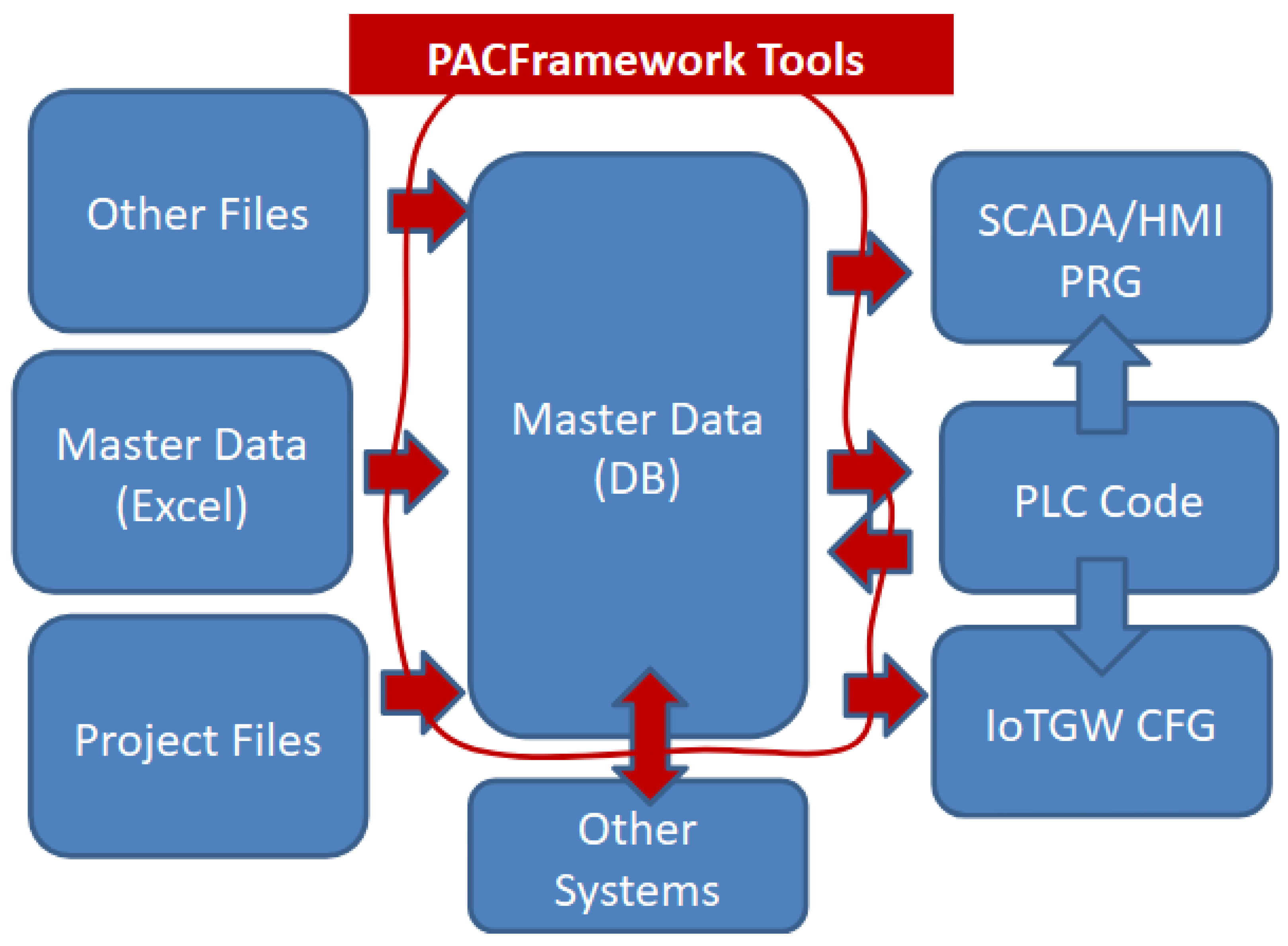
Figure 3.
PFw2 Infrastructure.
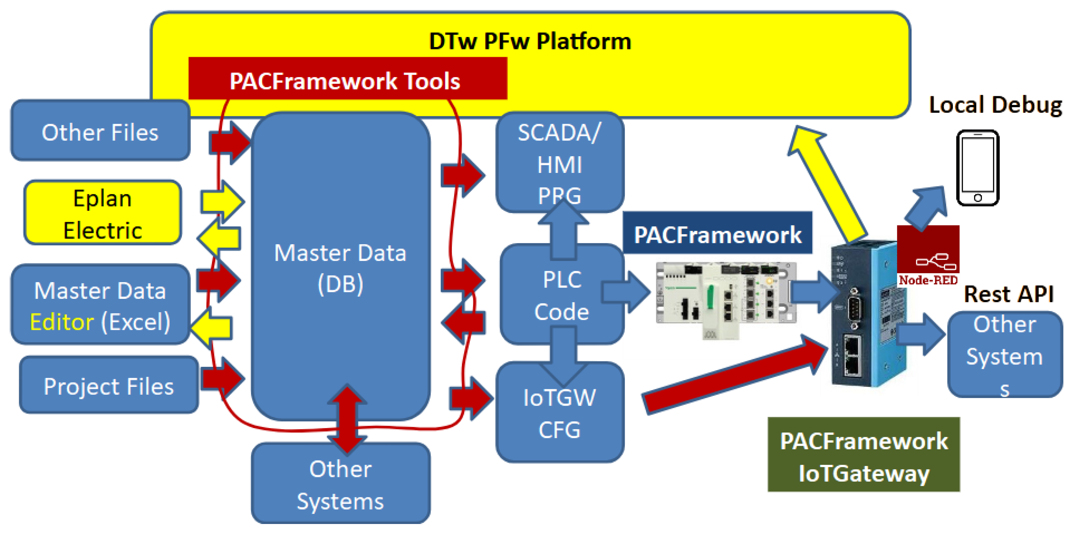
Figure 4.
Valve Representation on the P&ID.
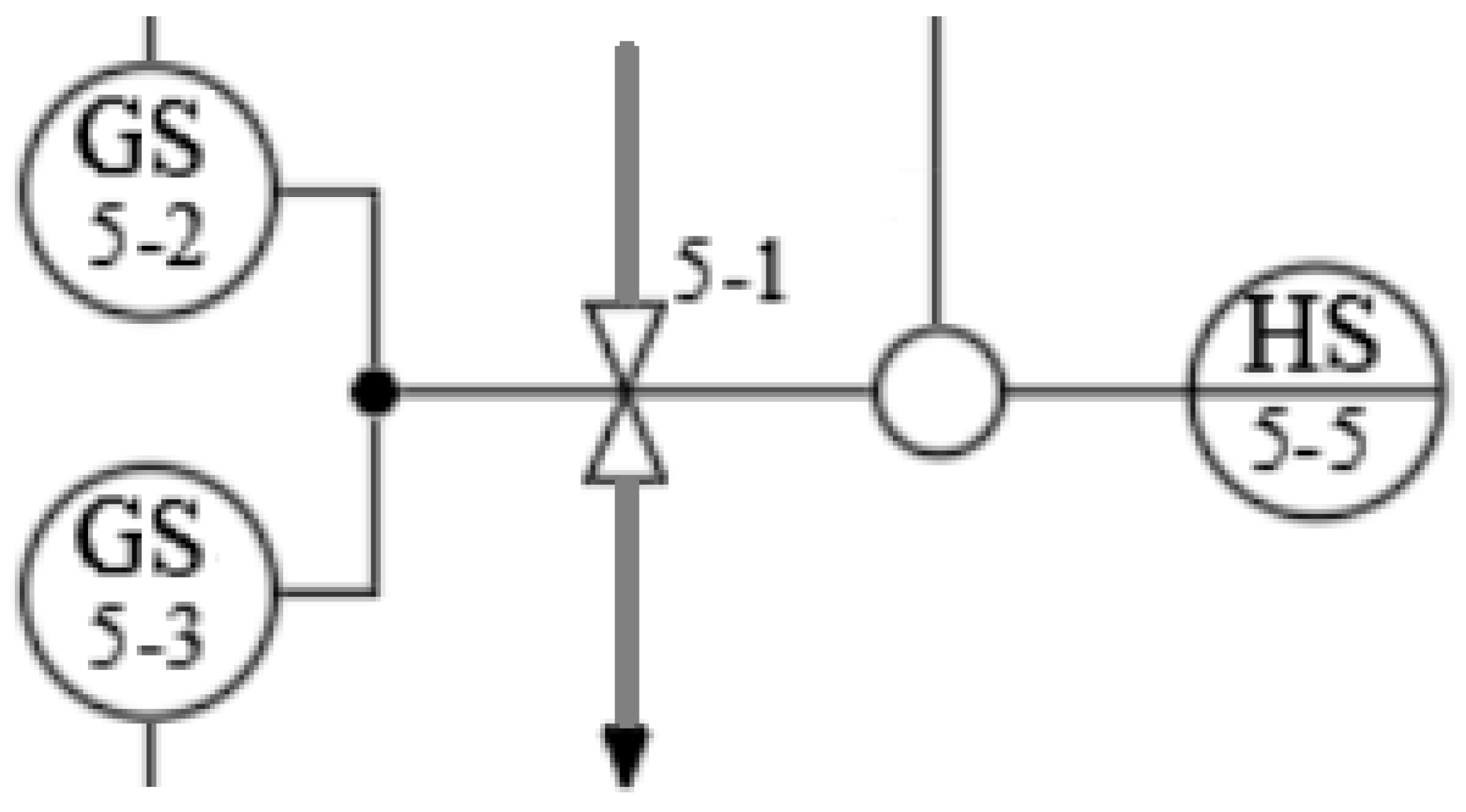
Figure 5.
Simplified alarm machine.
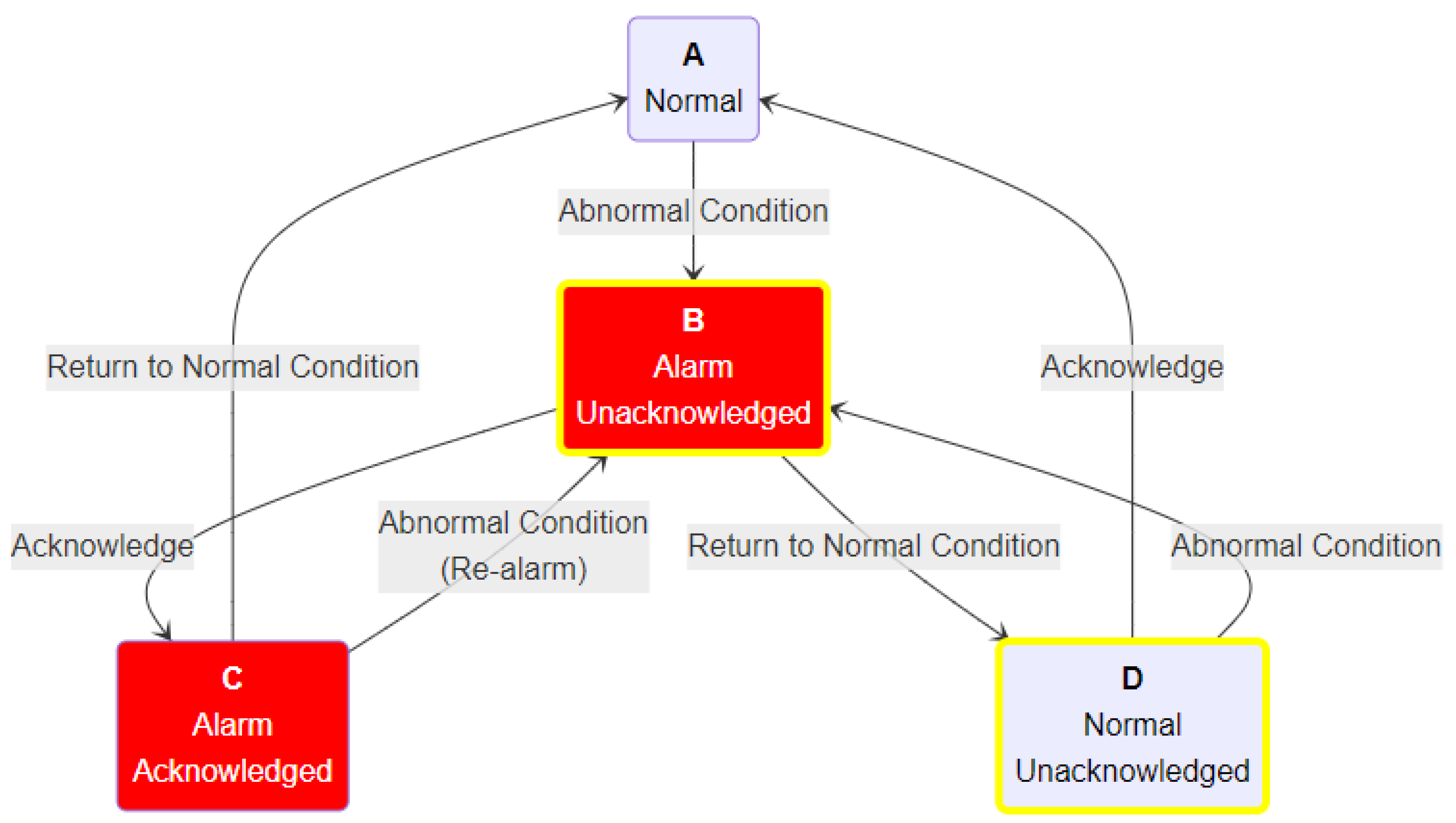
Figure 6.
Examples of basic valve state machines.
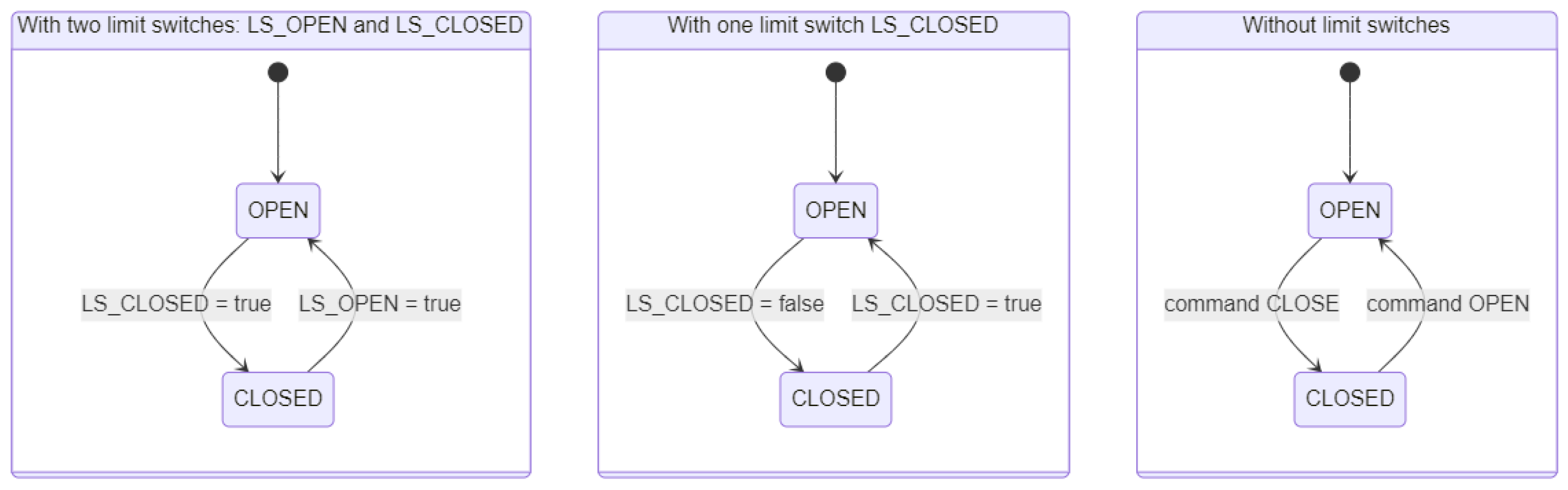
Figure 7.
Example of an extended state machine for a valve’s operational functional element.
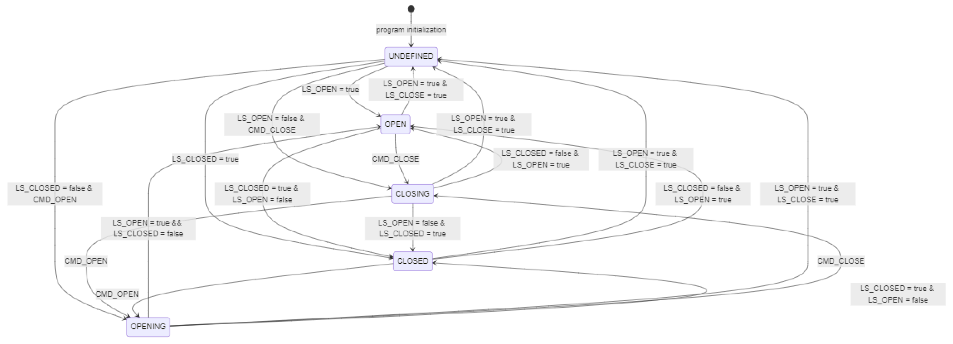
Figure 8.
Simplified State Machine Diagram for the “NOT CLOSED” Alarm.
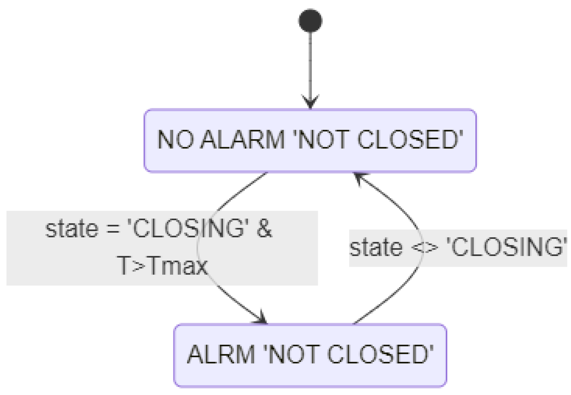
Figure 9.
State Machine for Switching Equipment Modes (Valve Type).
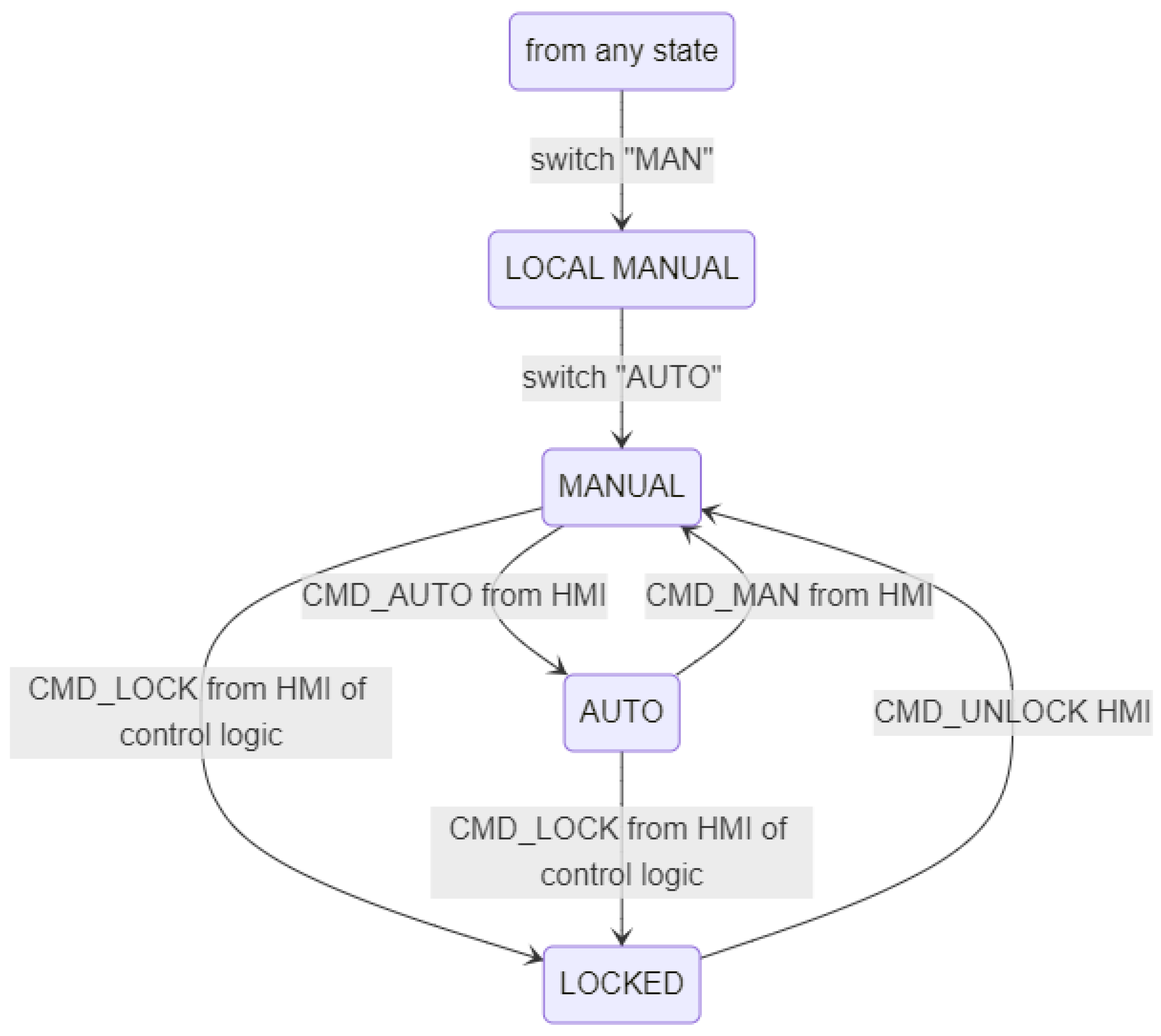
Figure 10.
Equipment hierarchy at the valve level.
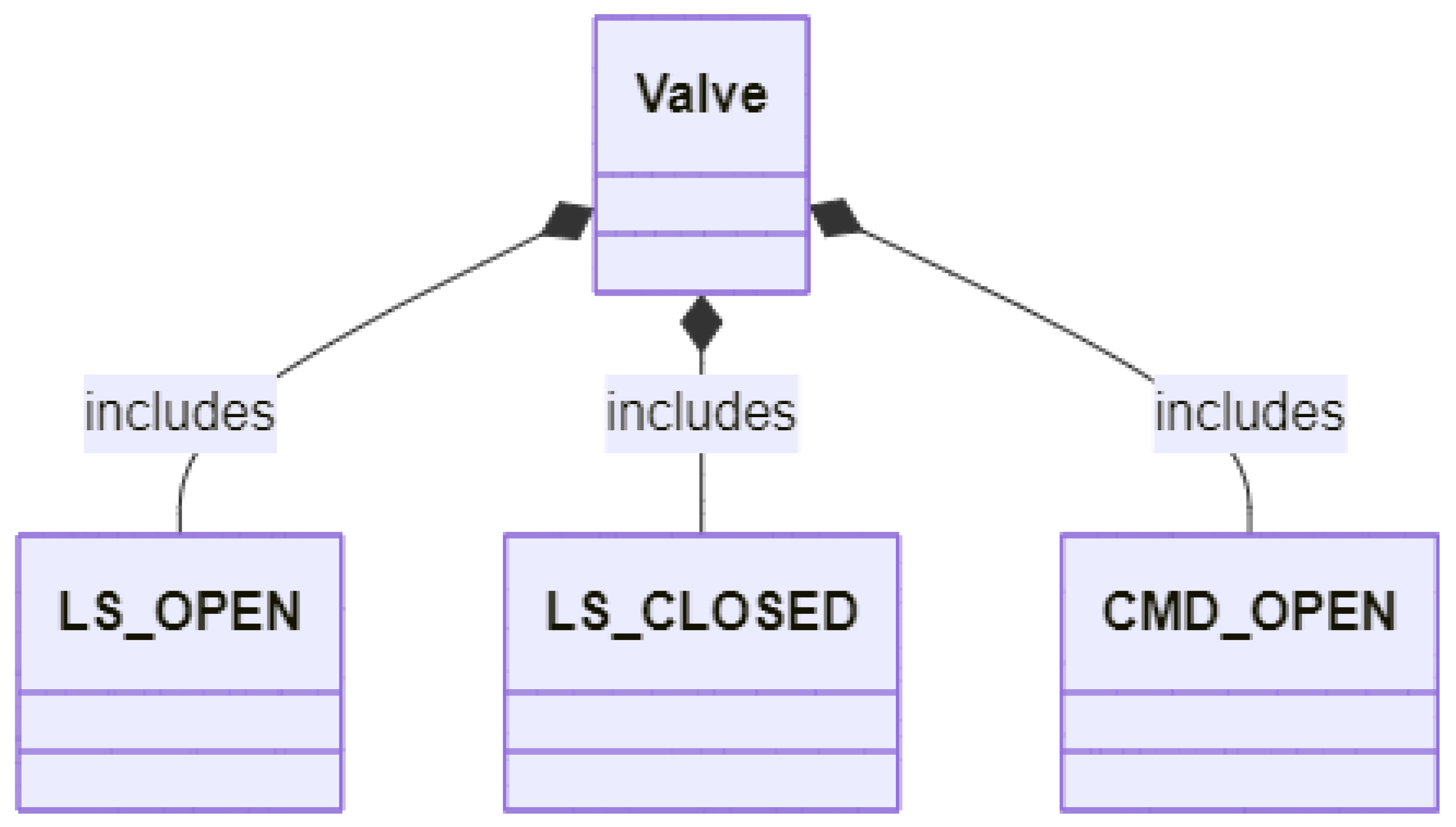
Figure 11.
Role-Based Equipment Hierarchy of an Enterprise (Source: [24]).
Figure 11.
Role-Based Equipment Hierarchy of an Enterprise (Source: [24]).
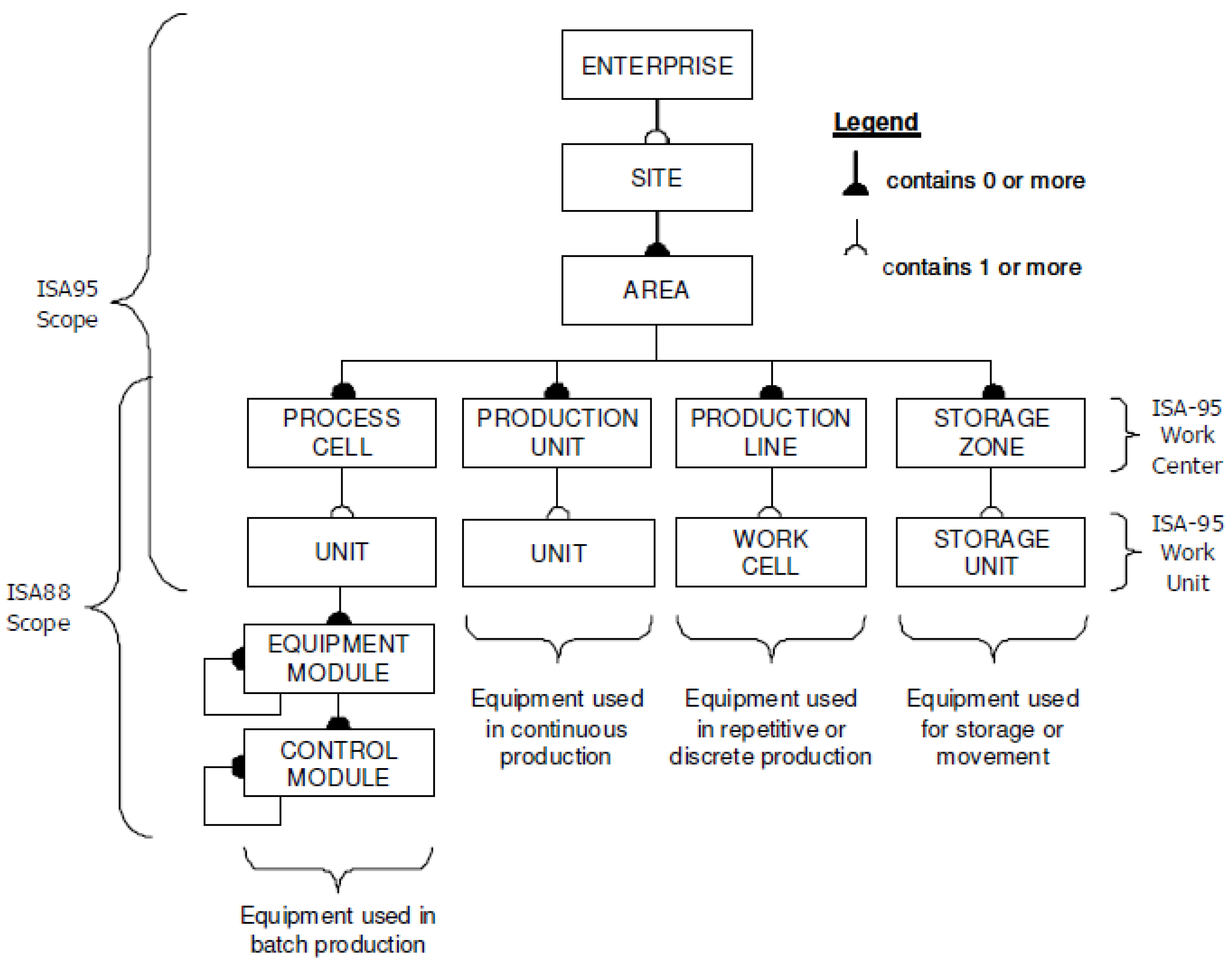
Figure 12.
Control Module Hierarchy.
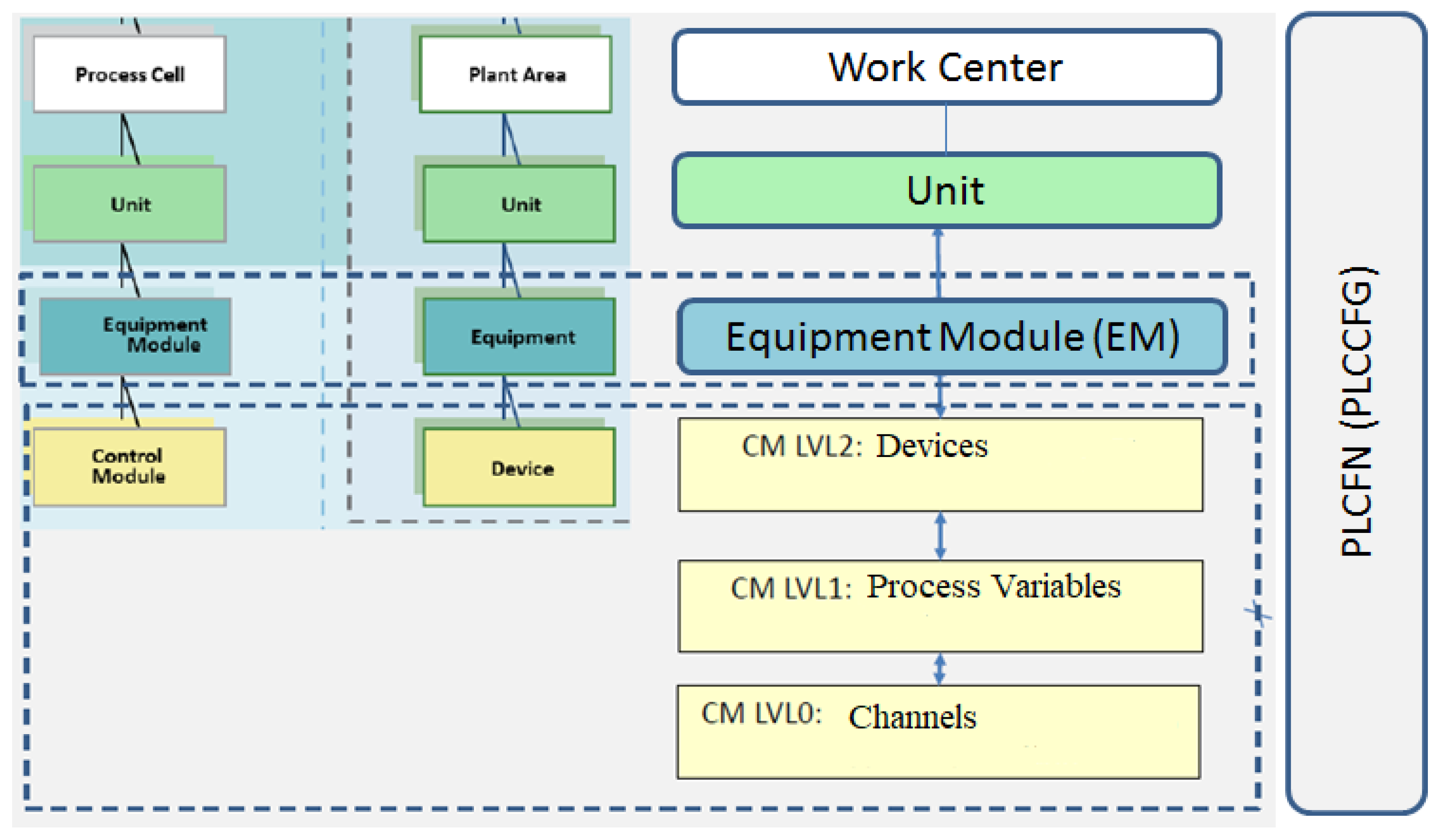
Figure 13.
Example of channel functions on the HMI (version with sufficient resources, Simatic Comfort Panel: TIA).
Figure 13.
Example of channel functions on the HMI (version with sufficient resources, Simatic Comfort Panel: TIA).
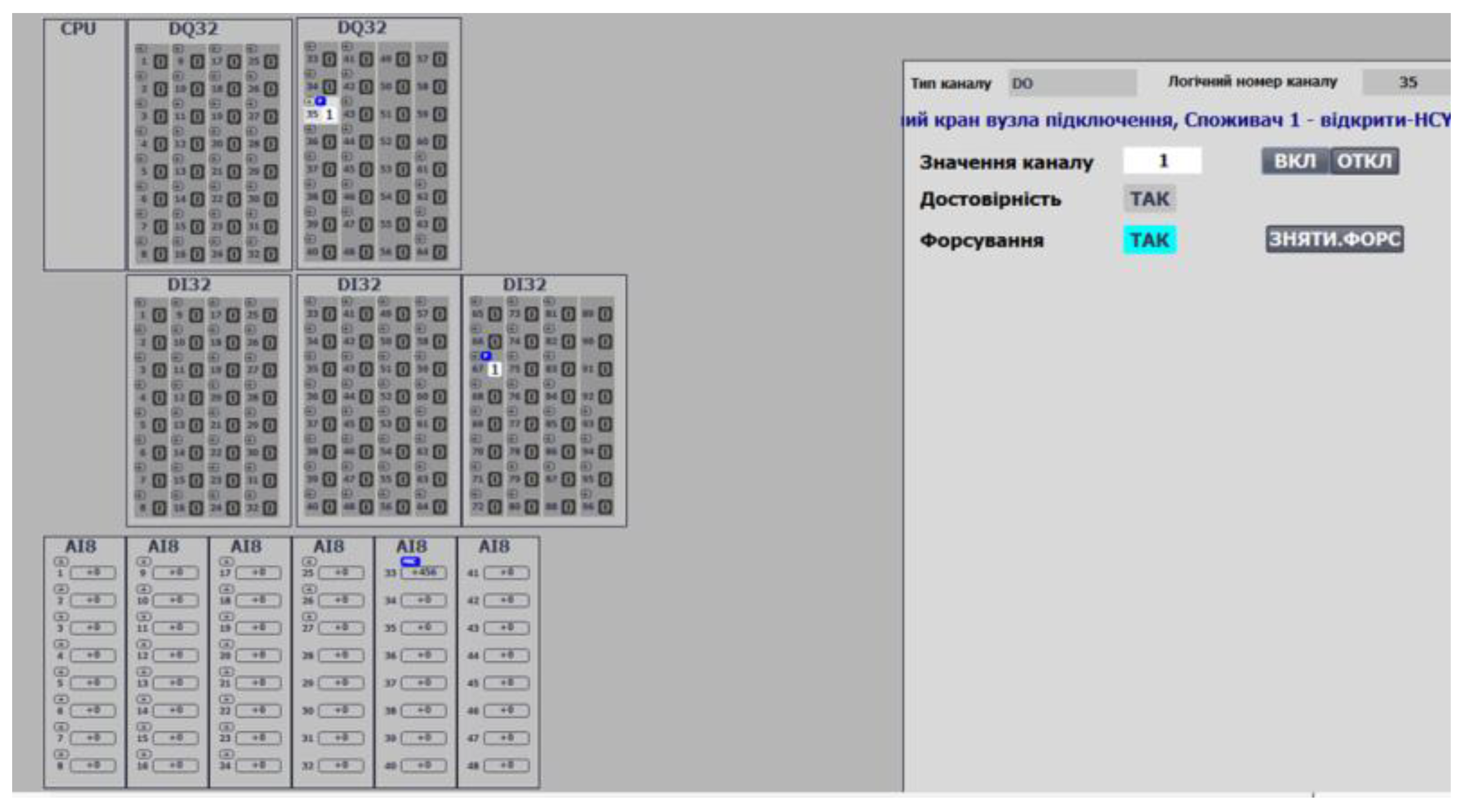
Figure 14.
Example of channel functions on the HMI (version with limited resources, Simatic Basic Panel: TIA).
Figure 14.
Example of channel functions on the HMI (version with limited resources, Simatic Basic Panel: TIA).
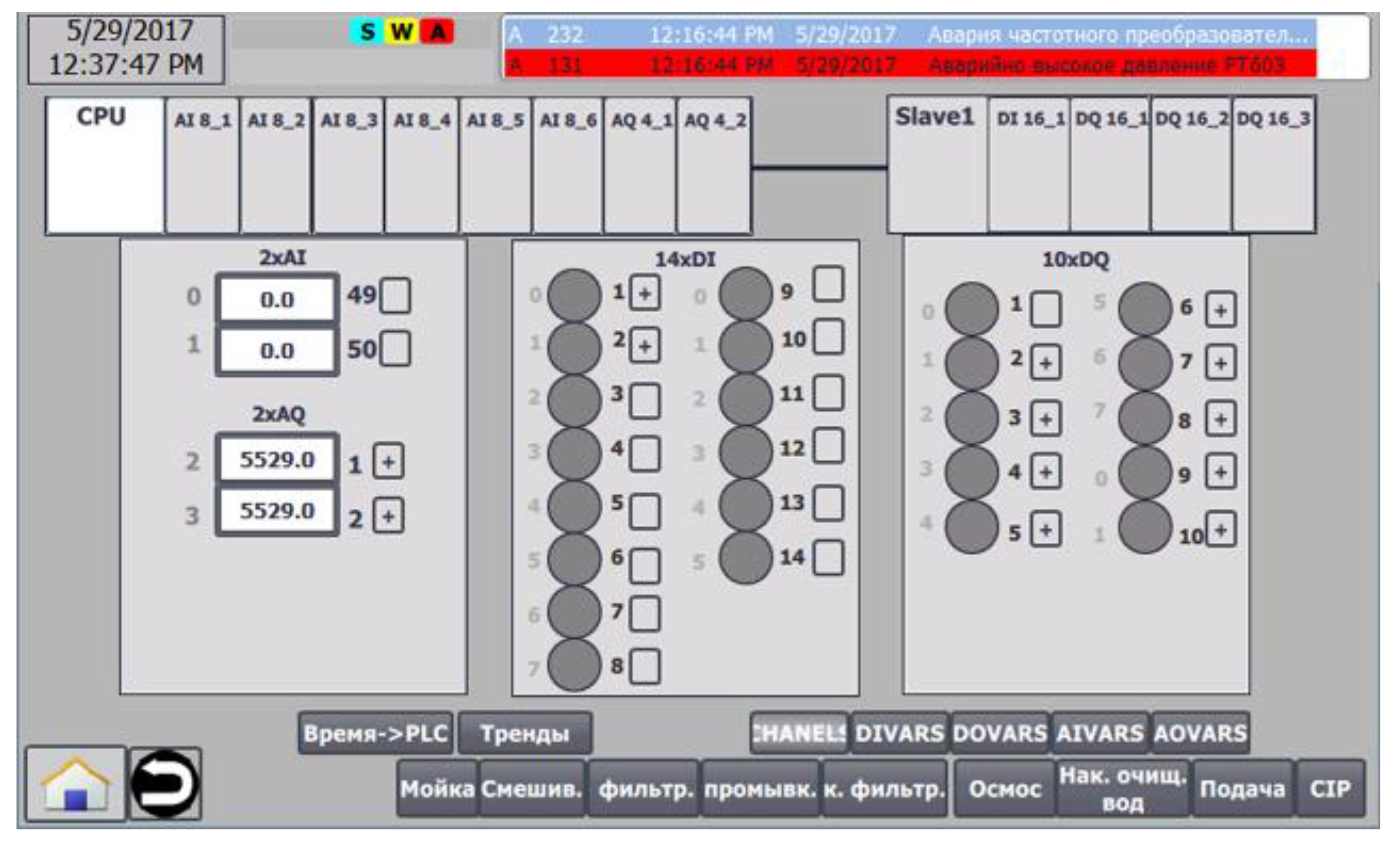
Figure 15.
Example of using MODULS and SUBMODULS .
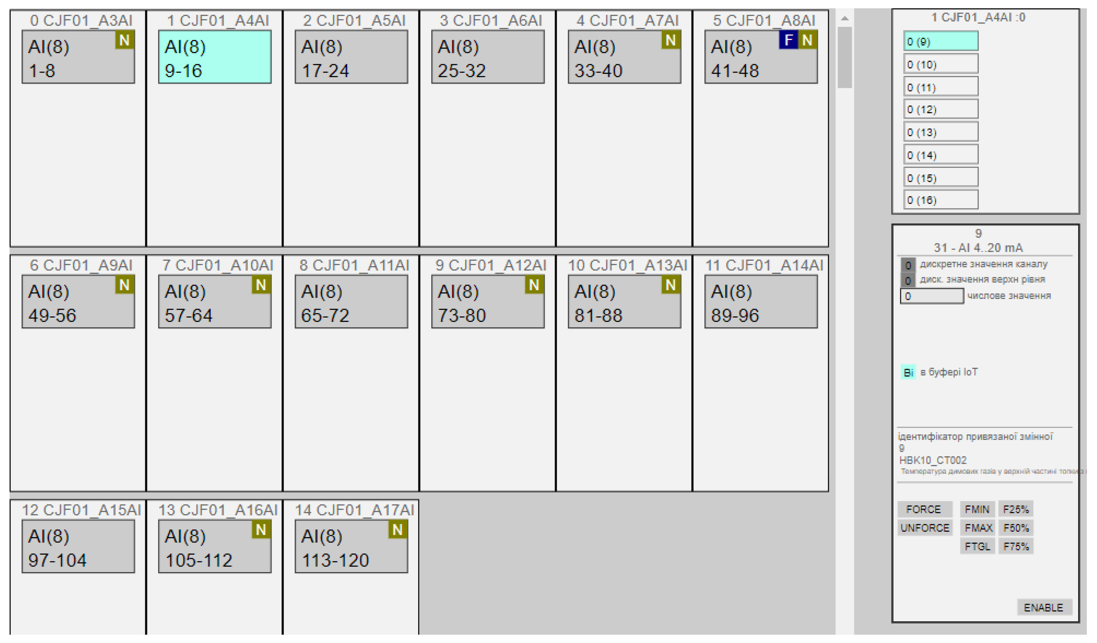
Figure 16.
Example of analog input variable functions on the HMI.
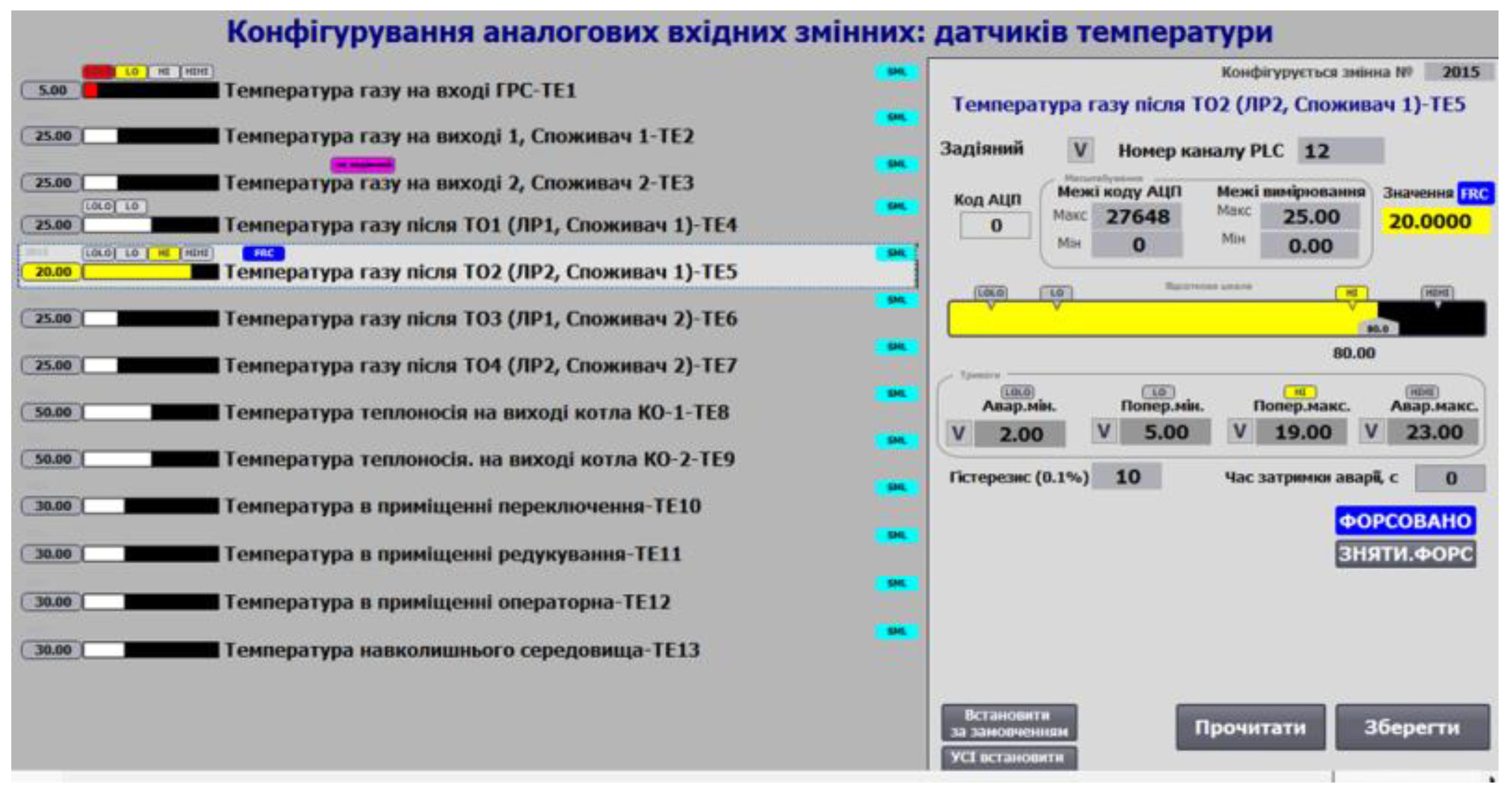
Figure 17.
Example of analog output variable functions on the HMI.
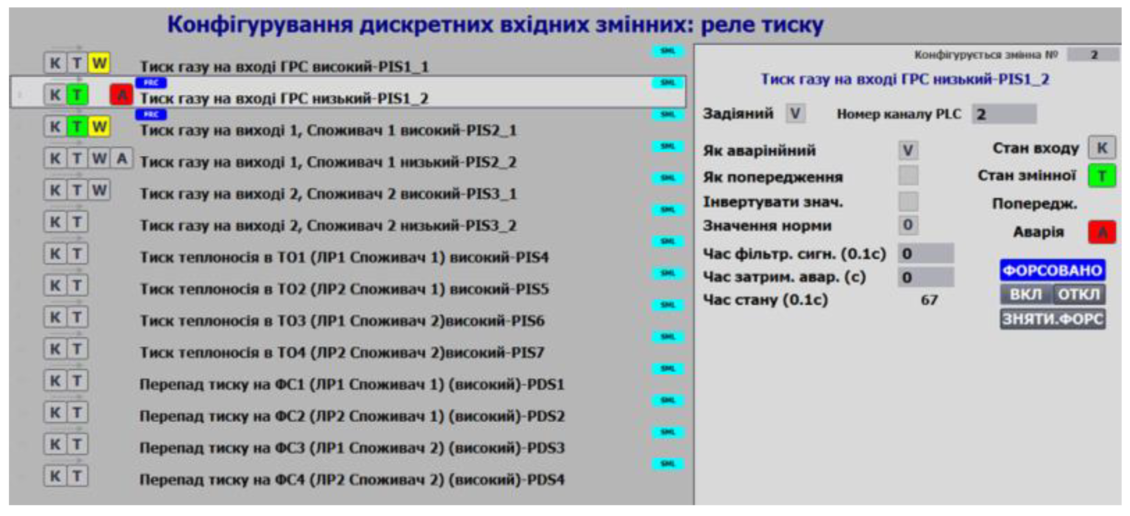
Figure 18.
Examples of variable status display on the HMI
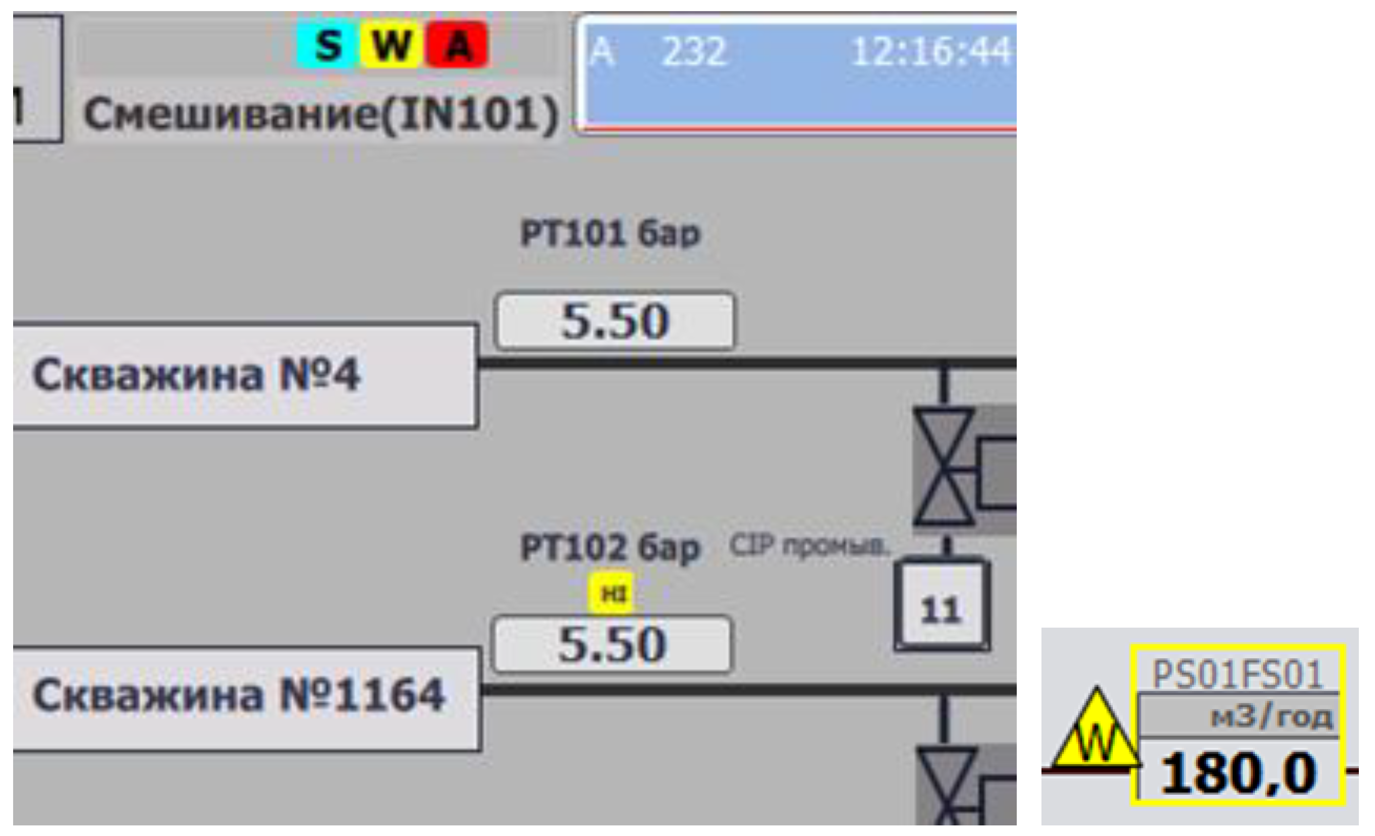
Figure 19.
Example of valve configuration on the HMI.
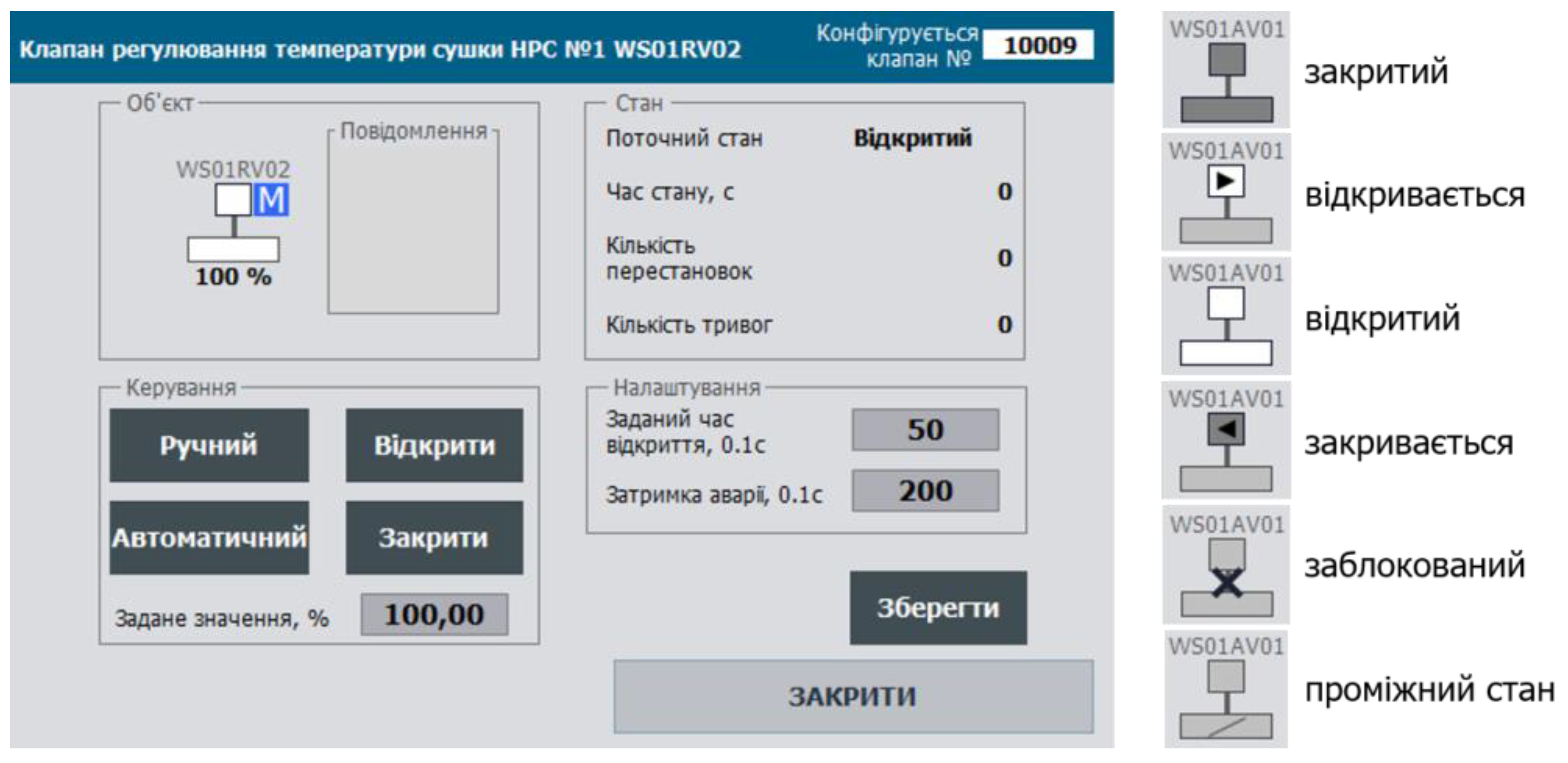
Figure 20.
Principles of Using a Buffer for Configuration Data Exchange.
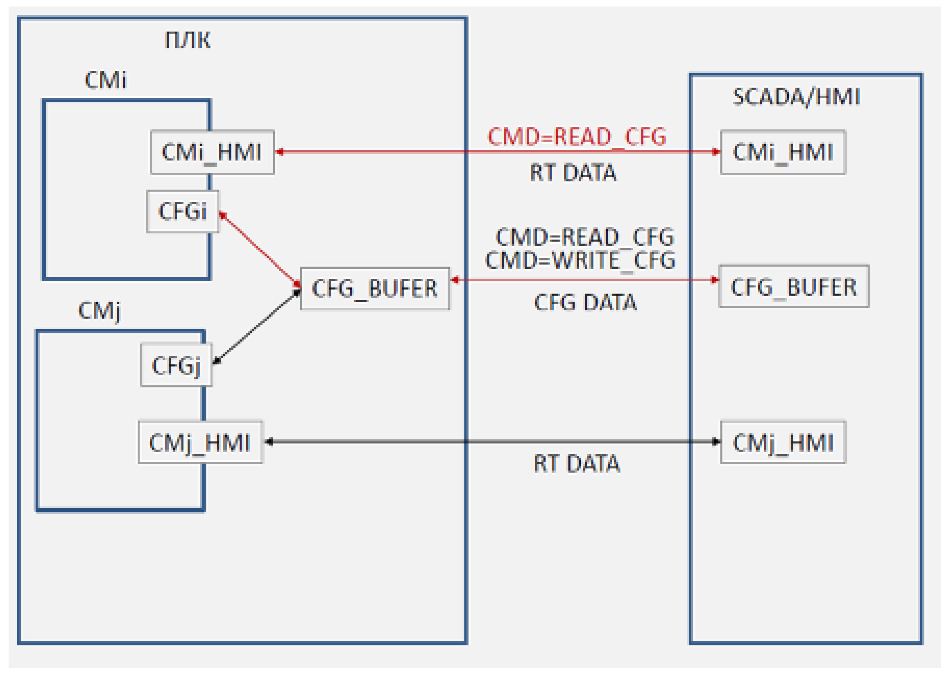
Figure 22.
Possible layout of the status panel.


Table 1.
Example of a status word for a 2-position valve.
| Bit | Description |
| 0 ALMOPN | = 1 alarm DOES NOT OPENED |
| 1 ALMCLS | = 1 alarm DOES NOT CLOSE |
| 2 BLCK | = 1 BLOCKED |
| 3 ALMSHFT | = 1 alarm RANDOM SHIFT |
| 4 ALMSNSR | = 1 alarm SENSOR ERROR |
| 5 OPNING | = 1 OPENING |
| 6 CLSING | = 1 CLOSING |
| 7 OPNED | = 1 OPENED |
| 8 CLSED | = 1 CLOSED |
| 9 DISP | = 1 MANUAL mode (with PC/OP), = 0 AUTOMATIC mode |
| 10 MANBX | = 1 LOCAL mode |
| 11 ALM | = 1 general alarm |
| 13 FRC | = 1 at least one of the variables in the object is forced |
| 14 SML | = 1 simulation mode |
Disclaimer/Publisher’s Note: The statements, opinions and data contained in all publications are solely those of the individual author(s) and contributor(s) and not of MDPI and/or the editor(s). MDPI and/or the editor(s) disclaim responsibility for any injury to people or property resulting from any ideas, methods, instructions or products referred to in the content. |
© 2025 by the author. Licensee MDPI, Basel, Switzerland. This article is an open access article distributed under the terms and conditions of the Creative Commons Attribution (CC BY) license (https://creativecommons.org/licenses/by/4.0/).
Copyright: This open access article is published under a Creative Commons CC BY 4.0 license, which permit the free download, distribution, and reuse, provided that the author and preprint are cited in any reuse.


