
Submitted:
08 July 2025
Posted:
09 July 2025
You are already at the latest version
Abstract
Midline diastemas are a common cosmetic concern in clinical practice. There are several causative factors of midline diastema. Treatment of midline diastema starts with recognizing the major etiology and mitigating it first. Among various treatment approaches, composite resins offer a conservative treatment that minimizes tooth loss, saves time, and necessitates fewer dental appointments and upkeeps. Since the shape, location, and color of teeth may be changed without sacrificing tooth substance, adhesive resin composite technology opens up new options for minimally invasive dentistry. This article describes cases where sectional and bioclear matrices were used to close the space with minimum amount of time. At two-year recall no sensitivities, discolorations, or fractures were detected on teeth and restorations.
Keywords:
anterior teeth
; bioclear matrix
; direct composite
; midline diastema
Introduction
The distance between two maxillary central incisors is known as the midline diastema. There are multiple physiological and pathological causes of midline diastema. It is physiologically seen as a normal growth pattern during the primary and mixed dentition eras. This stage is referred to as the "Ugly Duckling stage" and is usually corrected after the permanent maxillary canines erupt.
The most common causes of diastemas in adults are tooth size disparities and severe vertical overlap of the incisors. Labiolingual incisor inclination, frenum, generalized spacing, incisor mesiodistal angulation, and pathological state are other significant factors [1].
The direct-bonding restoration approach is the recommended therapeutic choice for cosmetic procedures. The maximum amount of tooth structure is preserved, and in a few clinical visits, function and appearance are restored. The procedure is also cost-effective and can delay the potential need for complex indirect restoration. For direct-bonding restorations, superior clinical expertise is required [2].
Research has shown that crowns, porcelain laminate veneers, and direct composite resin restorations are effective ways to treat anterior diastema [3]. Understanding the etiology and carefully planning the course of treatment are necessary before closing the diastema. The most typical method for closing diastemas is to prepare the tooth and use composite resin to restore it. Compared with all the other treatment alternatives, the restorative approach using composite resin is the least intrusive, cost-effective, and aesthetically pleasing procedure that may be completed in a single visit.
Case 1
A 23-year-old female patient visited our clinic with a chief complaint of an unpleasant gap between her upper central incisors. To enhance the appearance of the smile, the patient desired to close the middle diastema (Figure 1). This instance involved the use of a direct composite approach since she wanted a quick treatment that would preserve her enamel the best.
The "button technique" was used for color selection (Figure 2), which involved placing a section of composite on the structure and picking its color. The best option for choosing an enamel shade is to place the composite in the incisal third, where the thickness of the enamel allows for the observation of the enamel shade.
A rubber dam was used as a mode of isolation. Additionally, it is particularly helpful since it improves access to the teeth's cervical region by retracting the papillae [4]. The enamel surface was etched with 37% phosphoric acid for 20 second (Figure 3). Following a 40-second surface rinse, the tooth was thoroughly dried. For the highest bond strength quality and the smoothest transition between the composite and tooth surface, the etched area was marginally wider than the working area [5].Following the placement of the bioclear matrix, the bonding agent Tetric N-Bond (Ivoclar) was applied, and the composite was light cured at approximately 460 nm.
A small increment of flowable composite (Ivoclar Tetric N-flow) was injected into both teeth to fill the critical cervical area (Figure 4). The ideal material for this initial increment is a flowable composite rather than a paste composite [6]. Placing a paste composite in this space without creating cavities or disrupting the matrices would be practically impossible [7]. The uncured flowable composite was subsequently filled with paste composite. This procedure is known as the "Injection molding technique" and the "Snow plow technique." (Figure 5)
Once the restoration was complete, a polishing kit (Shofu Super Snap –X -Treme, 8 mm size, black (L507) was used to define the correct fundamental anatomy after the hypothetical transitional lines were drawn with a pencil (Figure 5). A red pencil was used for secondary characterization (Figure 6). These grooves are more open in the incisal region and narrower in the cervical region. We were able to achieve the best esthetics for the patient after the procedure (Figure 7a). On 2 years follow up, the restoration was intact with no failure.
Case 2
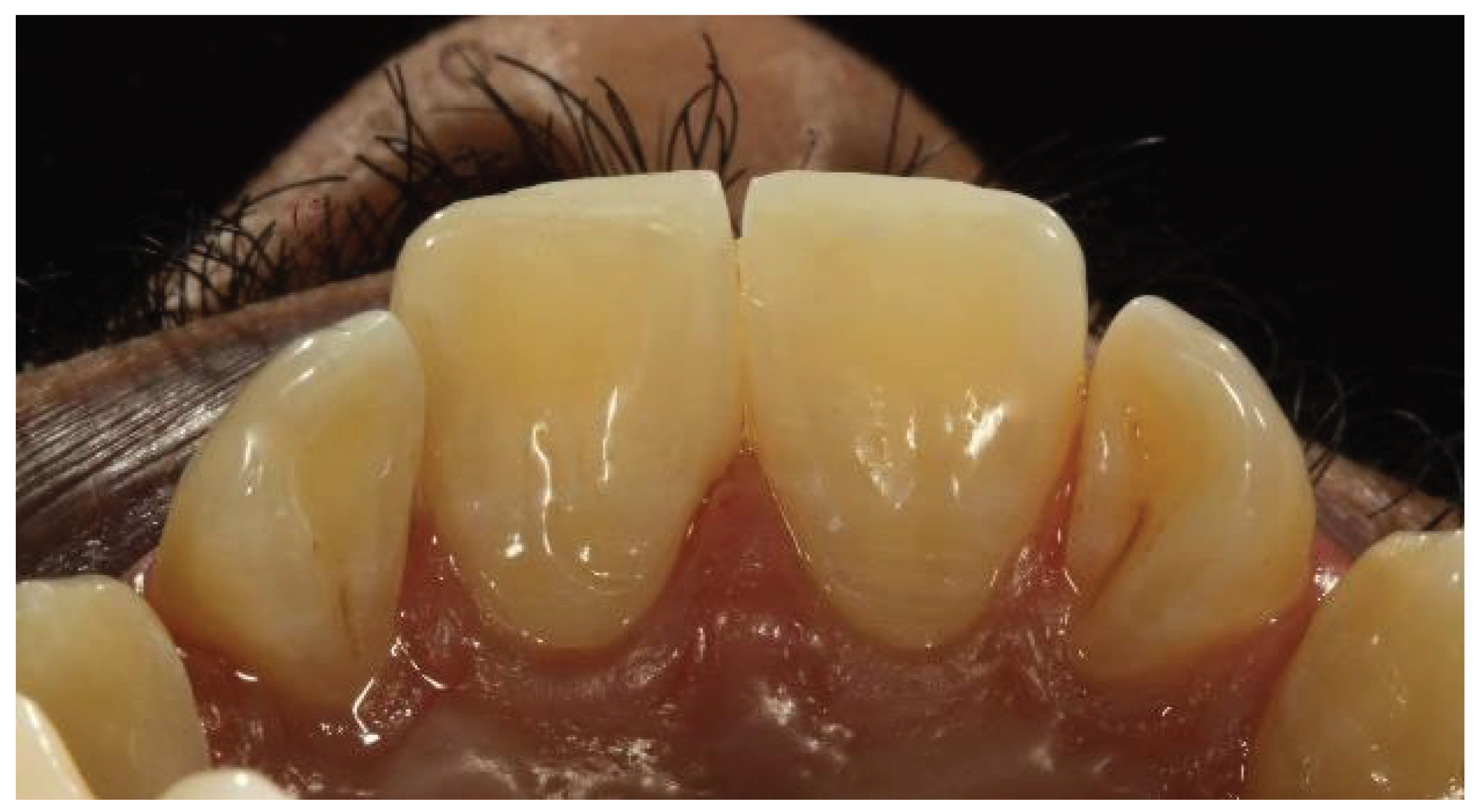
A 21 year-old female patient presented to our clinic with the primary complaint of psychological anguish caused by an unsightly appearance due to midline diastema (Figure 8).
The patient's medical history did not indicate any systemic disorders, and clinical examination revealed a significant gap between the maxillary central incisors. A periodontal examination revealed no pockets and confirmed the patient's dental hygiene. For both maxillary central incisors, direct aesthetic midline diastema closure via a composite layering approach was considered because it is a more expedient, conservative, inexpensive, and aesthetically pleasing option.
Preoperative radiographs were taken first. The tooth to be repaired was then shaded, and composite shade A2 (VITA classical shade guide) was chosen for the composite restoration (Figure 9). Isolation was achieved by placing a rubber dam (Figure 10). Both central incisor mesial surfaces were treated with 37% phosphoric acid for 15 seconds, washed for 20 seconds, and then lightly dried with air (Figure 11). To ensure proper contact between the two maxillary central incisors, bioclear matrices were positioned (Figure 12). The etched surface was coated twice with Ivoclar's Single Bond universal adhesive, (Figure 13), which was then air blasted until it stopped moving and polymerized for 20 second under LED light.
The cervical region was filled by gently inserting a small amount of flowable composite into both teeth (Figure 14). Paste composite was then used to fill the uncured flowable composite. After the line angles were marked (Figure 15), the restoration was finished and polished using a polishing kit (Shofu Super Snap Rainbow kit) and a smooth tapered diamond bur (Shofu preparation set). Detailed polishing from coarse to fine grains was accomplished with polishing discs and a low speed handpiece. The patient was happy with the outcome (Figure 16). At the 2-year follow up, the restoration was intact with no failure (Figure 17).
Case 3
A 27 year old colleague came to our dental facility to have her maxillary central incisors repaired. She was grumbling about the odd form and mismatched shades of the restored teeth (Figure 18). First, the shade was chosen prior to the tooth dehydration process. Before the case was managed, we found that the two incisors were joined by a composite. A diamond bur was used to cut the composite placed in the diastema, followed by rubber dam isolation (Figure 19). To harmonize the color of the tooth with that of the composite, enamel beveling is required (Figure 20). Featheredge bevel to the enamel surface is the preferred technique; chamfers or butt joints are not ideal. After the mechanical preparation of the tooth, light-cured calcium hydroxide was added to protect the pulp. 37% phosphoric acid was used to etch the enamel border (Figure 21).
Mylar strips were used to provide high translucency enamel shade for the palatal shell after several layers of bonding agent were used to strengthen the bond (Figure 22). Sectional matrices were applied to build proximal walls (Figure 23). The most crucial thing was to modify the composite on the band wall in an effort to prevent the emergence of gaps. (Figure 24). Once the tooth's contour was restored, we began applying the dentin composite portion from the bevel to the incisal area (Figure 25). To avoid compromising the final value and to provide the restorations with the necessary translucency and opalescence features, the final layer of enamel was made half as thick as the native tooth enamel. Red and led pencils were used to mark the primary and secondary characterizations (Figure 26).
The Shofu snap discs, eve twist polisher, sirona enhance finishing system, and fine diamond burs were used to complete the polishing and finishing process. We can appreciate the final outcome with proper contact and countour. (Figure 27).
Case 4
The patient was dissatisfied with the filling of her maxillary central incisors due to poor aesthetics (Figure 28). We started the re-restoration process by selecting the appropriate shade. By placing a section of composite on the structure and choosing its color, the "button technique" was used to choose the shade (Figure 29). To isolate the site effectively, rubber dam isolation was carried out (Figure 30). A Shofu Snap Kit Black Disk was used to prepare the tooth and remove the old filling (Figure 31).
37% phosphoric acid was used to etch the enamel surface for 20 seconds (Figure 32). The tooth was then thoroughly dried after 40 seconds of surface rinsing. A new incisal margin (Ivoclar A2E) was established using mylar strips (Figure 33). To verify the contact, two bioclear matrices were positioned (Figure 34). To fill this important cervical region, a tiny initial increment of flowable composite was carefully injected into both teeth (Figure 35). The uncured flowable composite was subsequently filled with paste composite. Following the completion of the restoration, the discs and burs were used to define the correct primary anatomy after the hypothetical primary lines were drawn (Figure 36, Figure 37, Figure 38). A photograph was taken after the rubber dam was removed. (Figure 39).
Case 5
The patient, a 23-year-old man, was referred to our dental office by his orthodontist to schedule the closure of several diastemas (Figure 40). The patient was concerned about the ceramic veneers as a choice of treatment. Despite being the most effective tool available to restorative dentists for achieving the highest level of aesthetics, indirect ceramic partial restorations are costly and typically require some tooth preparation. Direct composite veneers should be the first choice, particularly for young patients.
The management process began with rubber dam isolation, followed by shade selection and enamel etching with 37% phosphoric acid (Figure 41). Bioclear matrices were positioned between the central incisors, but the gap was still present (Figure 42). Therefore, we decided to make a palatal shell (Figure 43). The palatal expansion was created freehand toward the midline. To ensure that the diastema space was spread evenly, the palatal shell was extended to the midline, supporting the bioclear matrices (Figure 44). This important cervical region was filled by carefully injecting a small initial increment of flowable composite into both teeth. (Figure 45). After that, the paste composite was injected into the flowable, uncured composite and light cured. The final removal of the bioclear resulted in the following outcome (Figure 46). The principal line angles were drawn once the repair was complete (Figure 47). Finishing and polishing were performed with burs and discs (Figure 48). We can appreciate the final outcome after rubber dam application, as shown below (Figure 49, Figure 50).
Discussion
Closure of the diastema through direct adhesive restorations is a recommended procedure and is frequently accomplished by many clinicians. With the current trend toward minimally invasive dentistry, direct composite veneering has provided clinicians with the added advantage of achieving predictable aesthetic results with minimal trauma to teeth [8]. The size of the diastema is an important determinant when selecting the mode of treatment as well as the material for correction. When greater space closure is needed, orthodontics may be indicated to improve the aesthetic outcome. When a small diastema with teeth is in proper orthodontic alignment, no preparation of the tooth structure is necessary, and direct composite bonding may yield the desired result. Direct composite restorations are preferable to ceramic materials for opposing dentition [9]. In the event of an unforeseen fracture, they can be repaired more easily compared to costly and time-consuming repairs or remakes for porcelain alternatives [10].
After restoration, if the patient is not happy with the outcome, the restoration can be removed without damaging the tooth structure. Compared with other treatment options, such as indirect veneer and crowns, which cannot be performed in a single visit and requires a minimum of two to three visits, the time taken to close the gap is also very short, whereas orthodontic treatment takes approximately a few months to years [2].
The use of a rubber dam is important not only because it helps to avoid moisture contamination but also to obtain good gingival retraction, providing better access to the cervical area and enabling composite addition in areas previously occupied by gingival tissue, thus, avoiding non-esthetic black triangle [4].
One important aspect of composite resins is their ability to mimic dental enamel, with an overall survival rate higher than 88% for up to 10 years [11]. The only disadvantage of composite restoration is that these materials possess less fracture toughness, shear strength, and compressive strength and are not ideally suited for ultrahigh-stress areas found in certain clinical situations [12,13]. The presence of unmanaged parafunctional forces such as bruxism, Class III end-to-end occlusal schemes, or noxious oral habits such as nail biting can potentially jeopardize the longevity of direct composite resin restorations [14,15]. However, in our cases, at the two-year follow up, no fracture, discoloration, marginal leakage or de-bonding was noted.
By taking this into consideration and according to the positive results, an experienced dentist with proper case selection, using an appropriate technique and modern materials, can perform highly aesthetic and durable direct composite resin restorations that can satisfy patients under the conditions of the case presented.
Conclusions
The restorative method with composite resin is the least invasive, reversible, economic and aesthetic treatment, which can be performed in a single visit in comparison with all other available treatment options. Midline diastema has a complex etiology. Management relies heavily on accurate diagnosis and timing. Good retention is the key to success in midline diastema closure.
Funding
This research did not receive any specific grant from funding agencies in the public, commercial, or not-for-profit sectors.
Ethical Approval
Ethical approval was not needed, as the format of this paper is a case series.
Data Availability Statement
The data that support the findings of this study are available upon request from the corresponding author. The data are not publicly available due to privacy or ethical restrictions.
Clinical Trial Number
Not applicable
Informed Consent Statement
Written informed consent was obtained from the patients for the publication of this case and accompanying images. A copy of the written consent is available for review by the Editor-in-chief of this journal upon request.
References
- Oesterle, L.J.; Shellhart, W.C. Maxillary midline diastemas: A look at the causes. The Journal of the American Dental Association. 1999, 130, 85–94. [Google Scholar] [CrossRef] [PubMed]
- Azzaldeen, A.; Muhamad, A.H. Diastema closure with direct composite: Architectural gingival contouring. J Adv Med Dent Sci Res. 2015, 3, 134–139. [Google Scholar]
- Bhoyar, A.G. Esthetic closure of diastema by porcelain laminate veneers: A case report. PJSR. 2011, 4, 47–50. [Google Scholar]
- de Campos, P.R.; Maia, R.R.; de Menezes, L.R.; Barbosa, I.F.; da Cunha, A.C.; da Silveira Pereira, G.D. Rubber dam isolation--key to success in diastema closure technique with direct composite resin. International Journal of Esthetic Dentistry. 2015, 10. [Google Scholar]
- Buonocore, M.G. A simple method of increasing the adhesion of acrylic filling materials to enamel surfaces. Journal of dental research. 1955, 34, 849–853. [Google Scholar] [CrossRef] [PubMed]
- Chuang, S.F.; Jin, Y.T.; Liu, J.K.; Chang, C.H.; Shieh, D.B. Influence of flowable composite lining thickness on Class II composite restorations. OPERATIVE DENTISTRY-UNIVERSITY OF WASHINGTON-. 2004, 29, 301–308. [Google Scholar]
- Gomaa, M.M.; Mosallam, R.S.; Abou-Auf, E.A.; Hassanien, O.E. Clinical evaluation of “Snowplow” technique versus Bulk-fill technique in restoration of class II cavities: A randomized clinical trial. Journal of International Oral Health. 2024, 16, 158–165. [Google Scholar] [CrossRef]
- Lal, S.M.; Jagadish, S. Direct composite veneering technique producing a smile design with a customised matrix. Journal of Conservative Dentistry and Endodontics. 2006, 9, 87–92. [Google Scholar] [CrossRef]
- Magne, P.; Belser, U.C. Porcelain versus composite inlays/onlays: Effects of mechanical loads on stress distribution, adhesion, and crown flexure. International Journal of Periodontics & Restorative Dentistry 2003, 23. [Google Scholar]
- Berksun, S.; Kedici, P.S.; Saglam, S. Repair of fractured porcelain restorations with composite bonded porcelain laminate contours. The Journal of Prosthetic Dentistry. 1993, 69, 457–458. [Google Scholar] [CrossRef] [PubMed]
- Lempel, E.; Lovász, B.V.; Meszarics, R.; Jeges, S.; Tóth, Á.; Szalma, J. Direct resin composite restorations for fractured maxillary teeth and diastema closure: A 7 years retrospective evaluation of survival and influencing factors. Dental Materials. 2017, 33, 467–476. [Google Scholar] [CrossRef] [PubMed]
- Jordan, R.E. Esthetic composite bonding: Techniques and materials. (No Title). 1993.
- Stappert, C.F.; Ozden, U.; Gerds, T.; Strub, J.R. Longevity and failure load of ceramic veneers with different preparation designs after exposure to masticatory simulation. The Journal of prosthetic dentistry. 2005, 94, 132–139. [Google Scholar] [CrossRef] [PubMed]
- Hickel, R.; Heidemann, D.; Staehle, H.J.; Minnig, P.; Wilson, N.H. Direct composite restorations: Extendes use in anterior and posterior situations. Clinical oral investigations. 2004, 8. [Google Scholar]
- Hemmings, K.W.; Darbar, U.R.; Vaughan, S. Tooth wear treated with direct composite restorations at an increased vertical dimension: Results at 30 months. The Journal of prosthetic dentistry. 2000, 83, 287–293. [Google Scholar] [CrossRef] [PubMed]
Figure 1.
Preoperative image showing midline diastema.
Figure 2.
Button technique for shade selection.
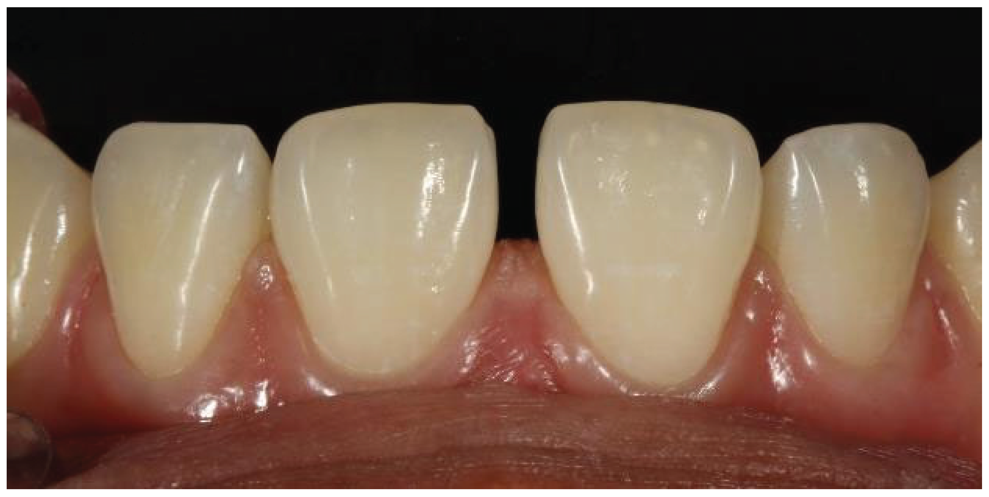
Figure 3.
Acid ethcing with 37% phosphoric acid after rubber dam isolation.
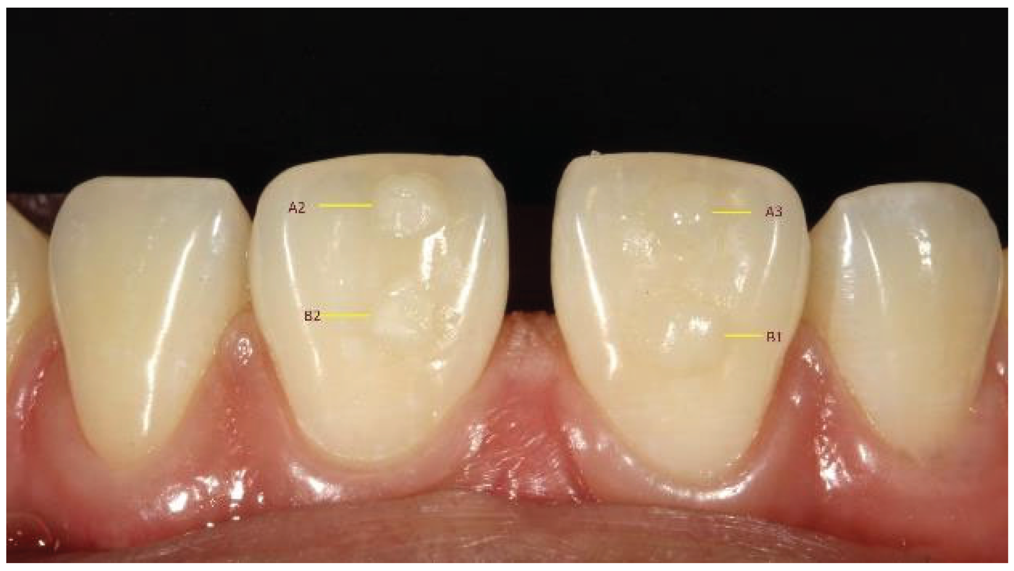
Figure 4.
Flowable composite filling in the cervical area after placement of the bioclear matrices.
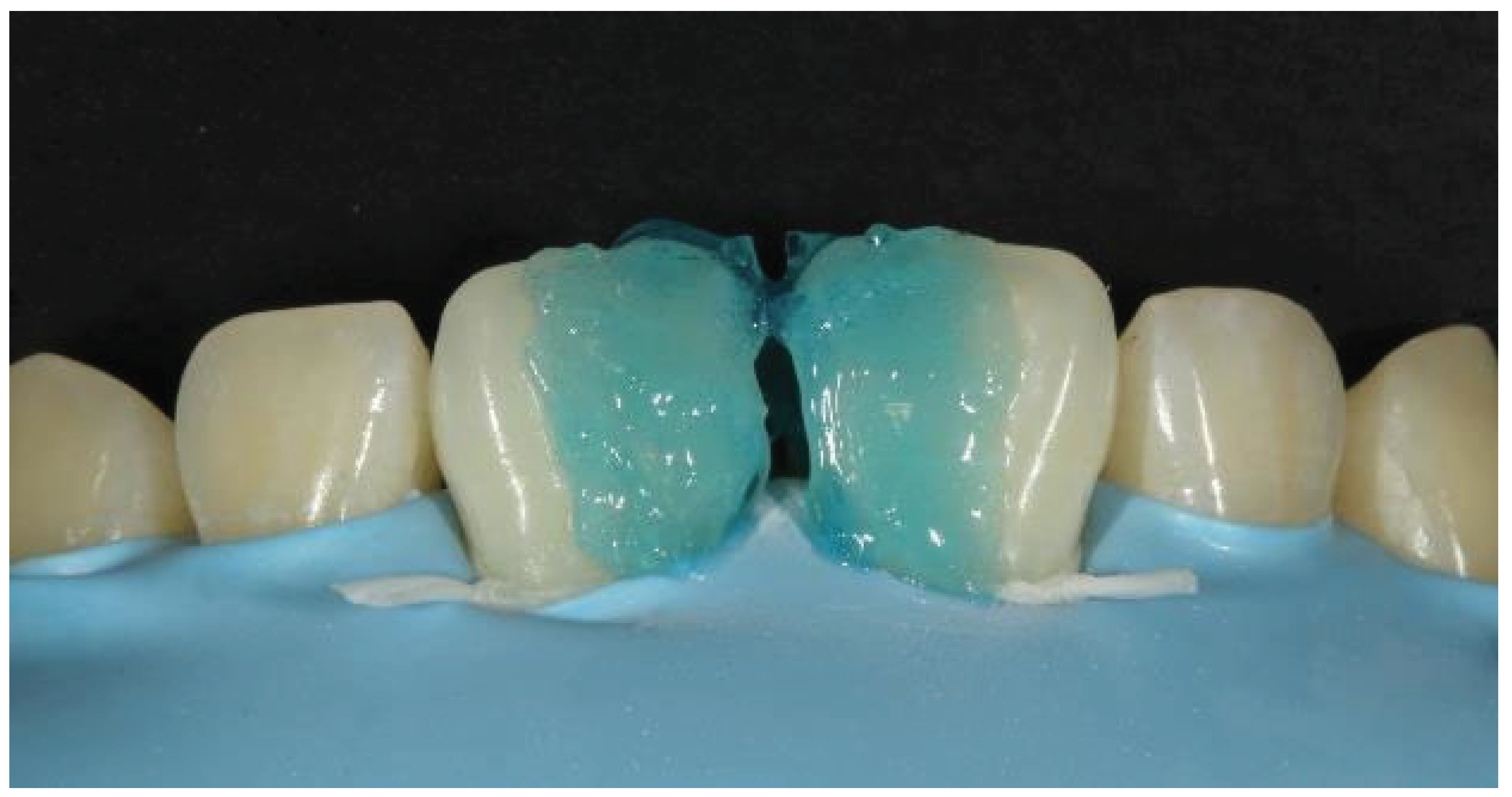
Figure 5.
Uncured flowable composite subsequently filled with paste composite.
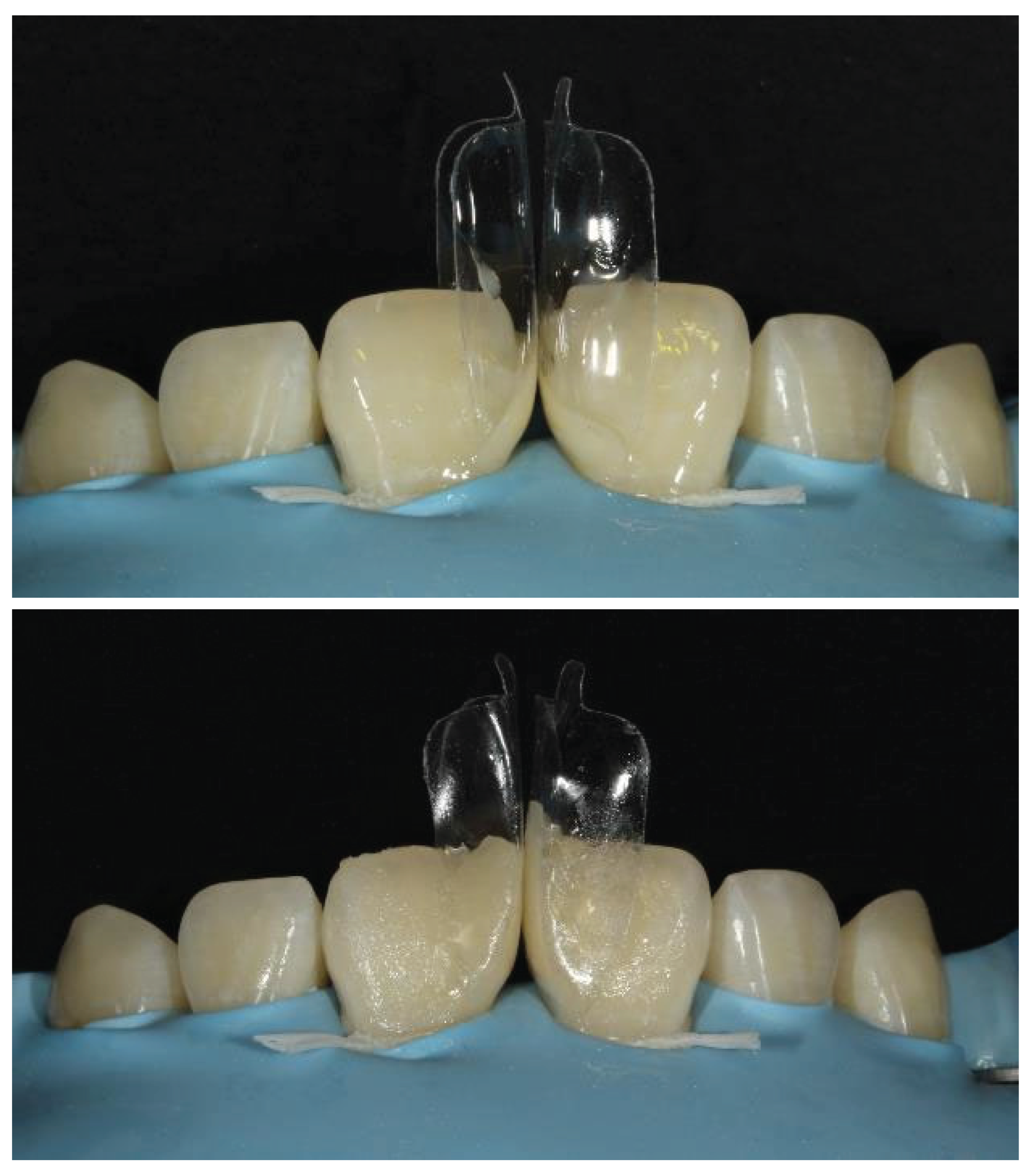
Figure 6.
Grooves for showing secondary characterization.
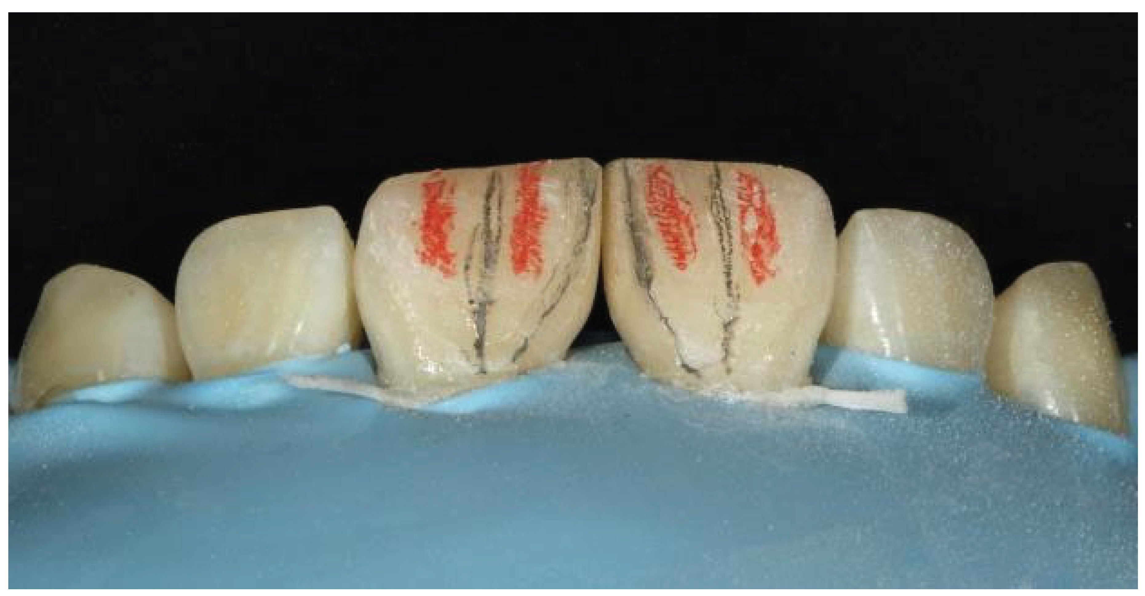
Figure 7a.
Final outcome immediately after removal of the rubber dam.
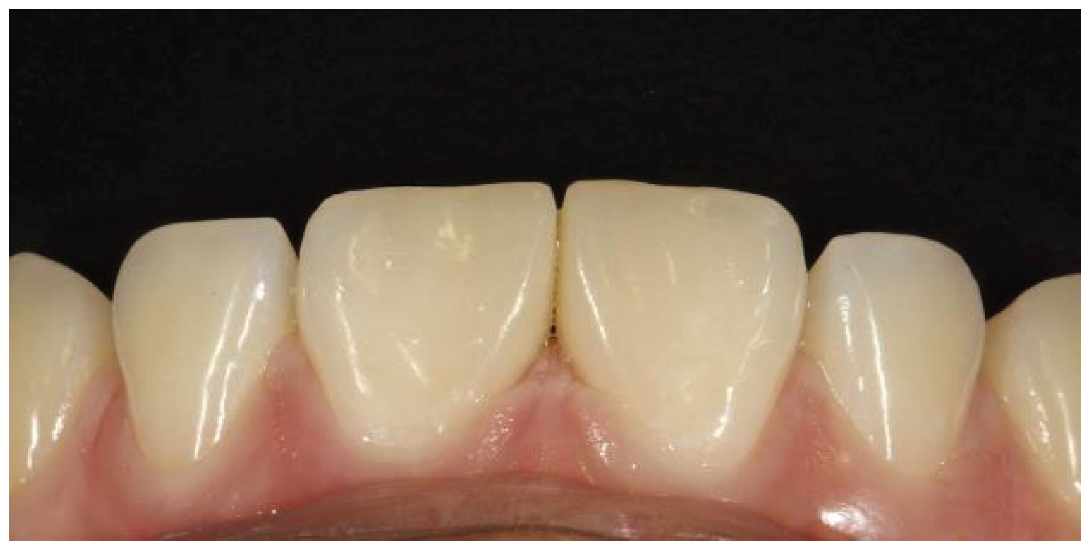
Figure 7b.
2 years follow up.
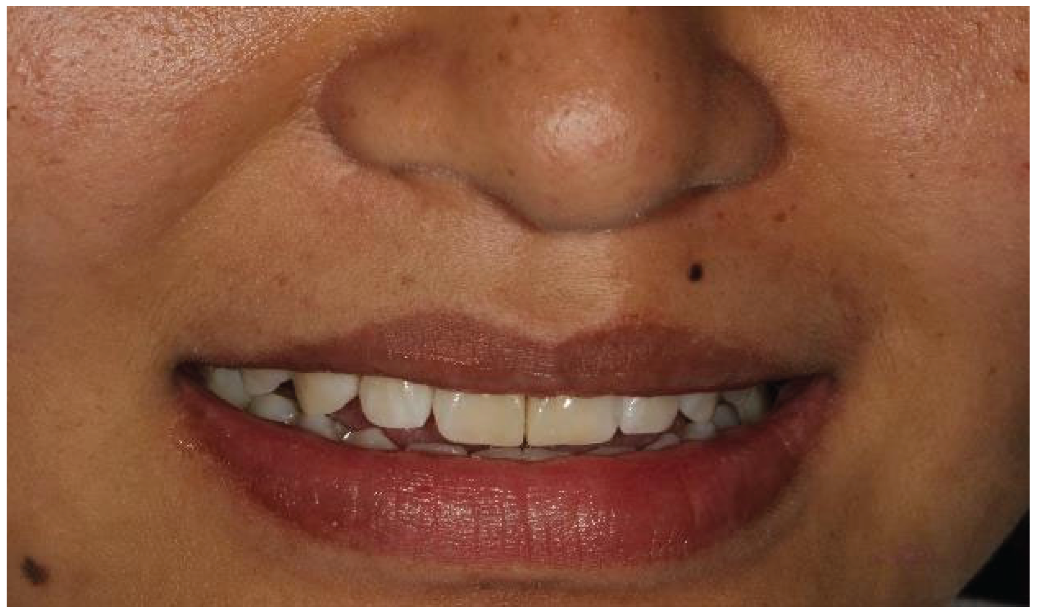
Figure 8.
Clinical image showing midline diastema.
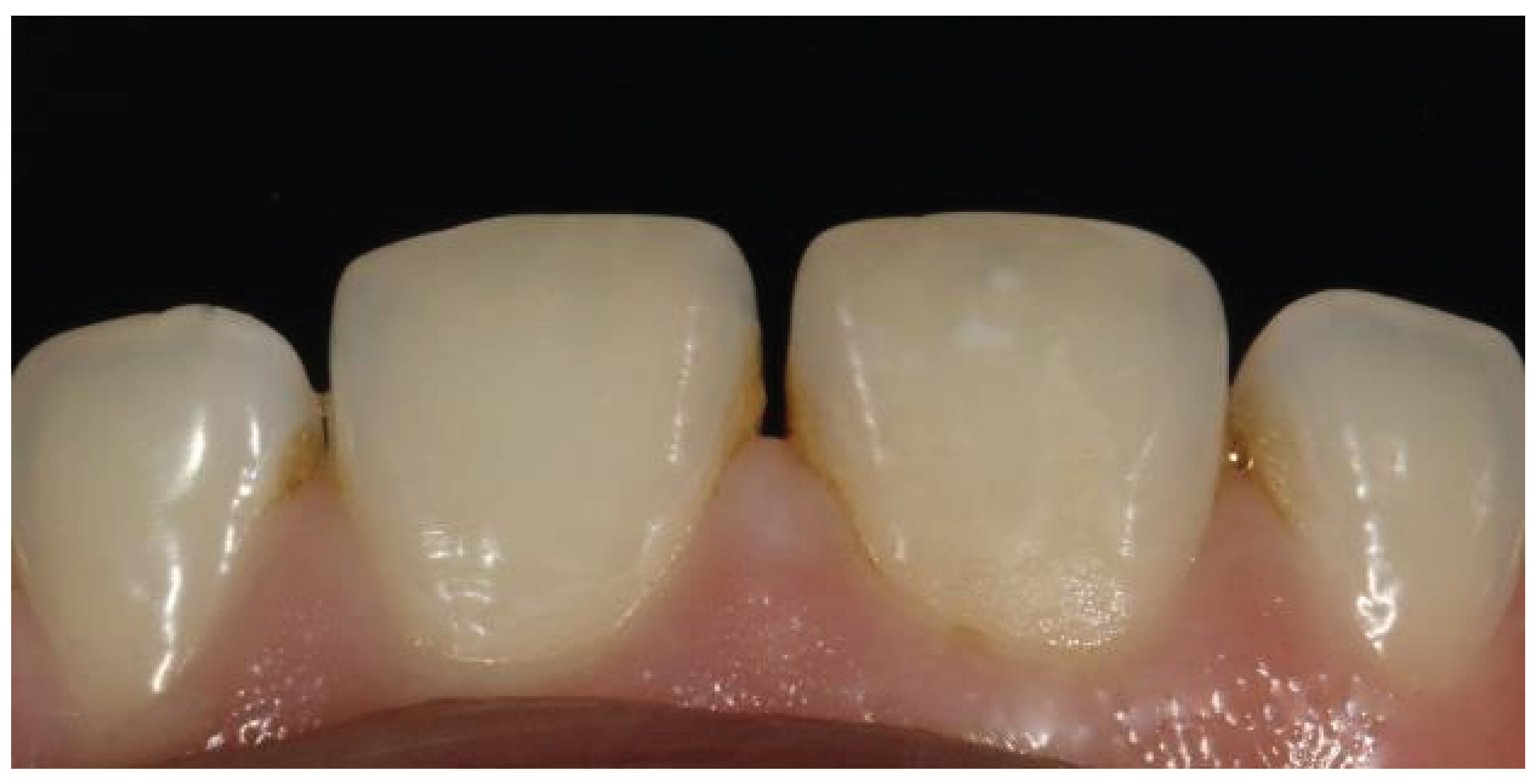
Figure 9.
Shade selection.
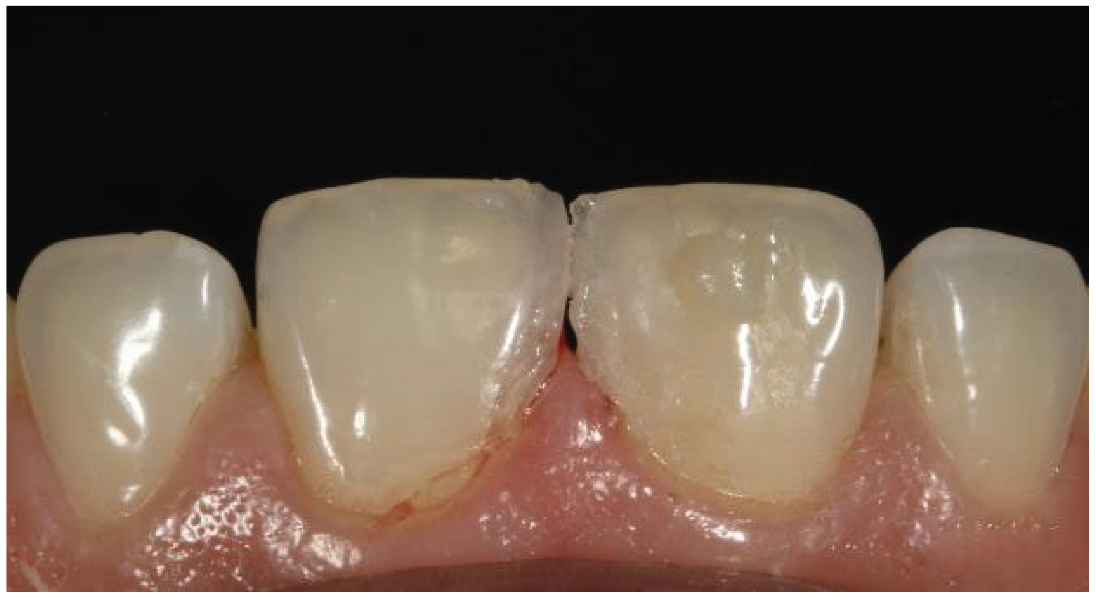
Figure 10.
Application of the rubber dam.
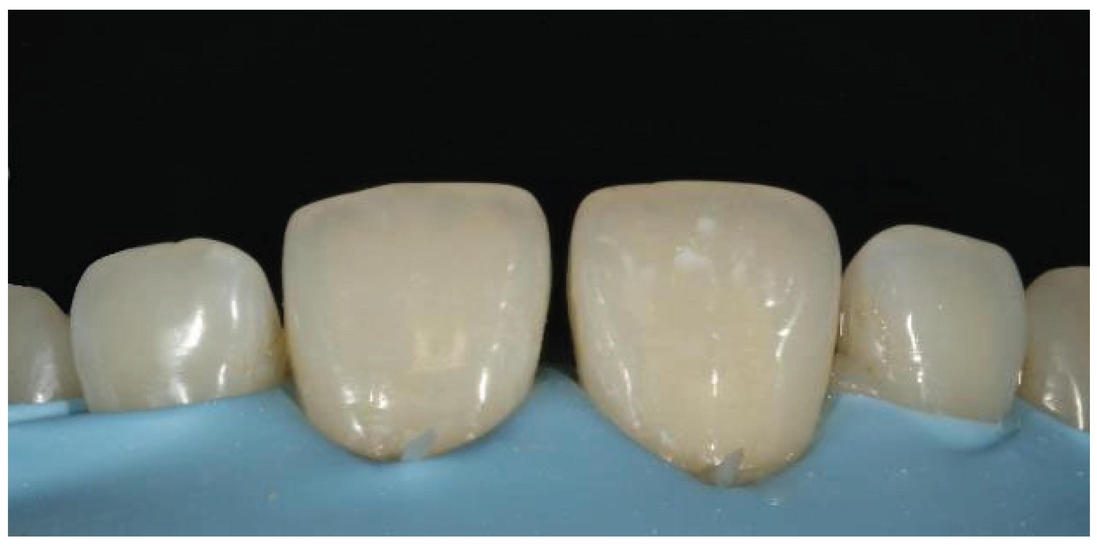
Figure 11.
Etching with 37% phosphoric acid.
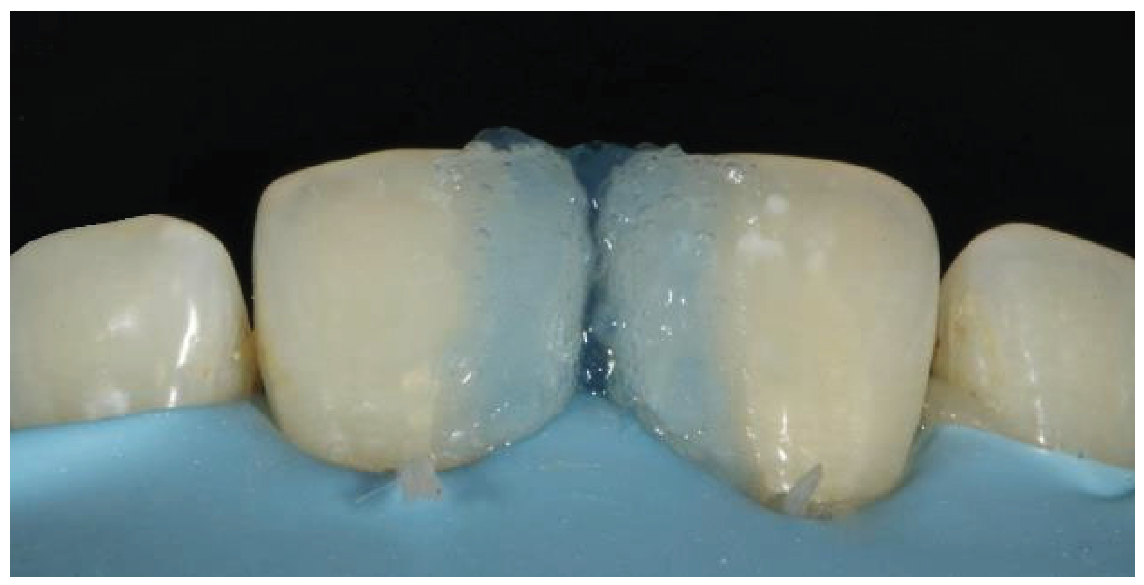
Figure 12.
Placement of the bioclear matrices.
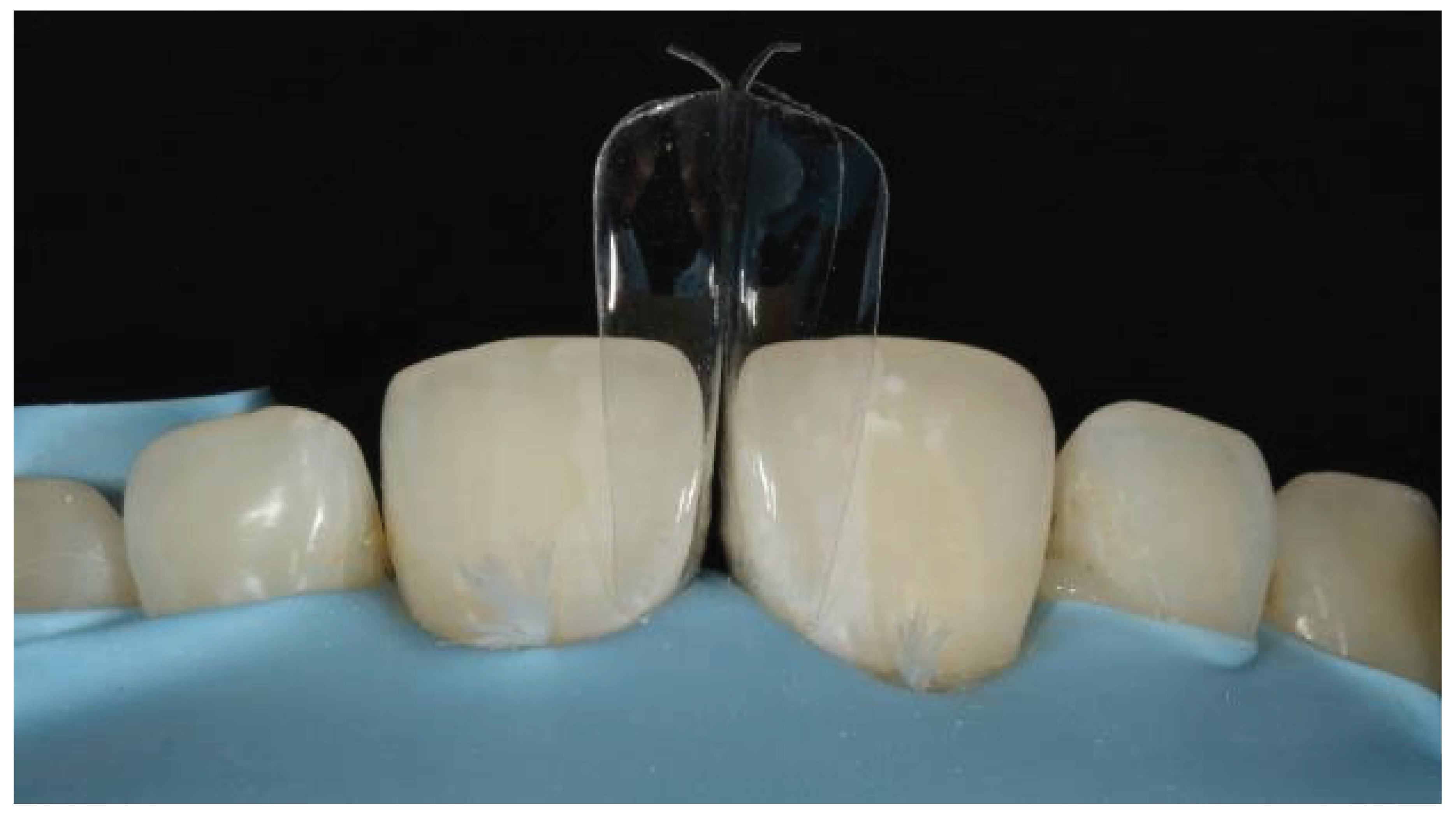
Figure 13.
Application of the bonding agent.
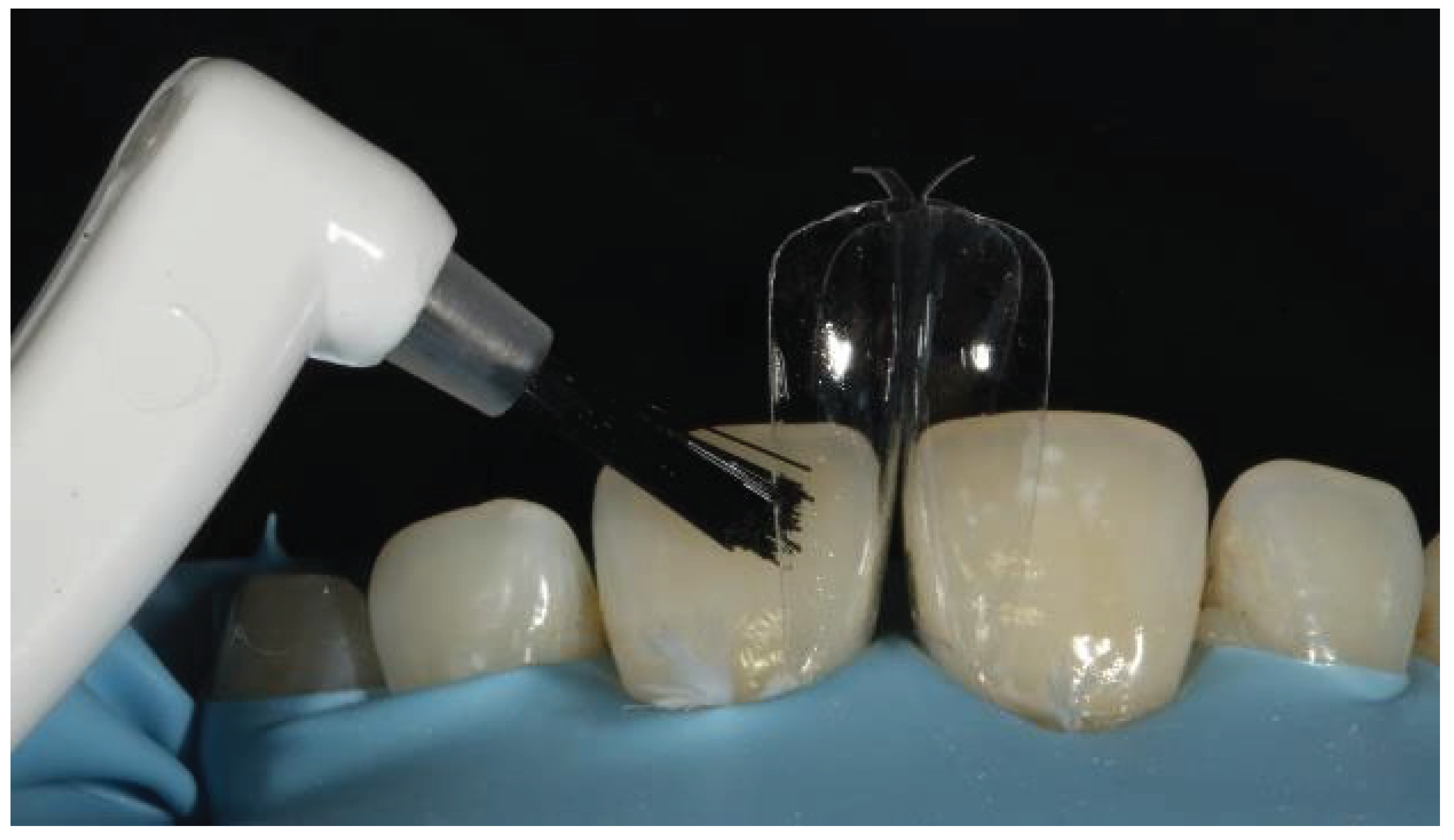
Figure 14.
Placement of the flowable composite in the cervical region.
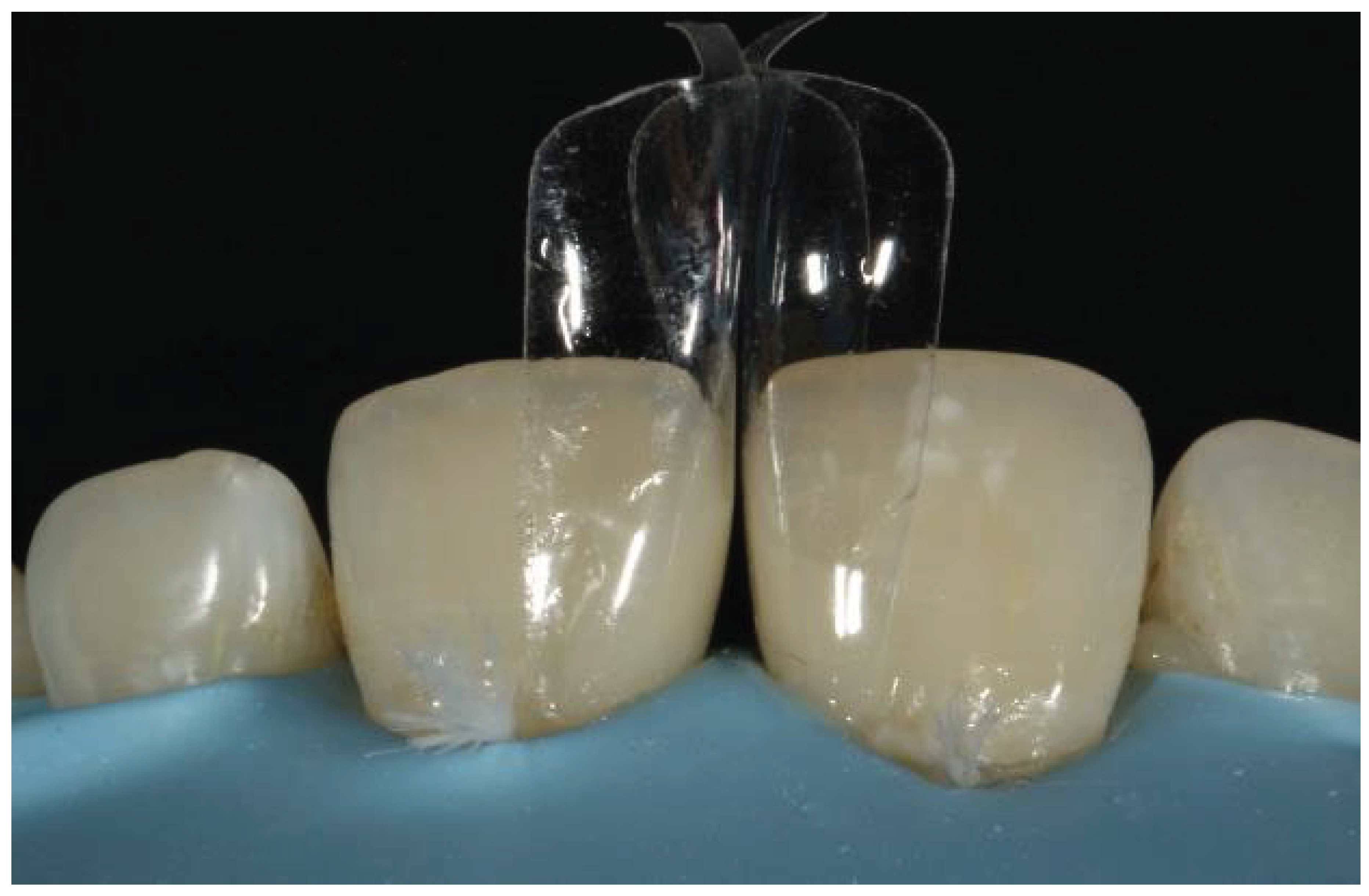
Figure 15.
Line angle marking.
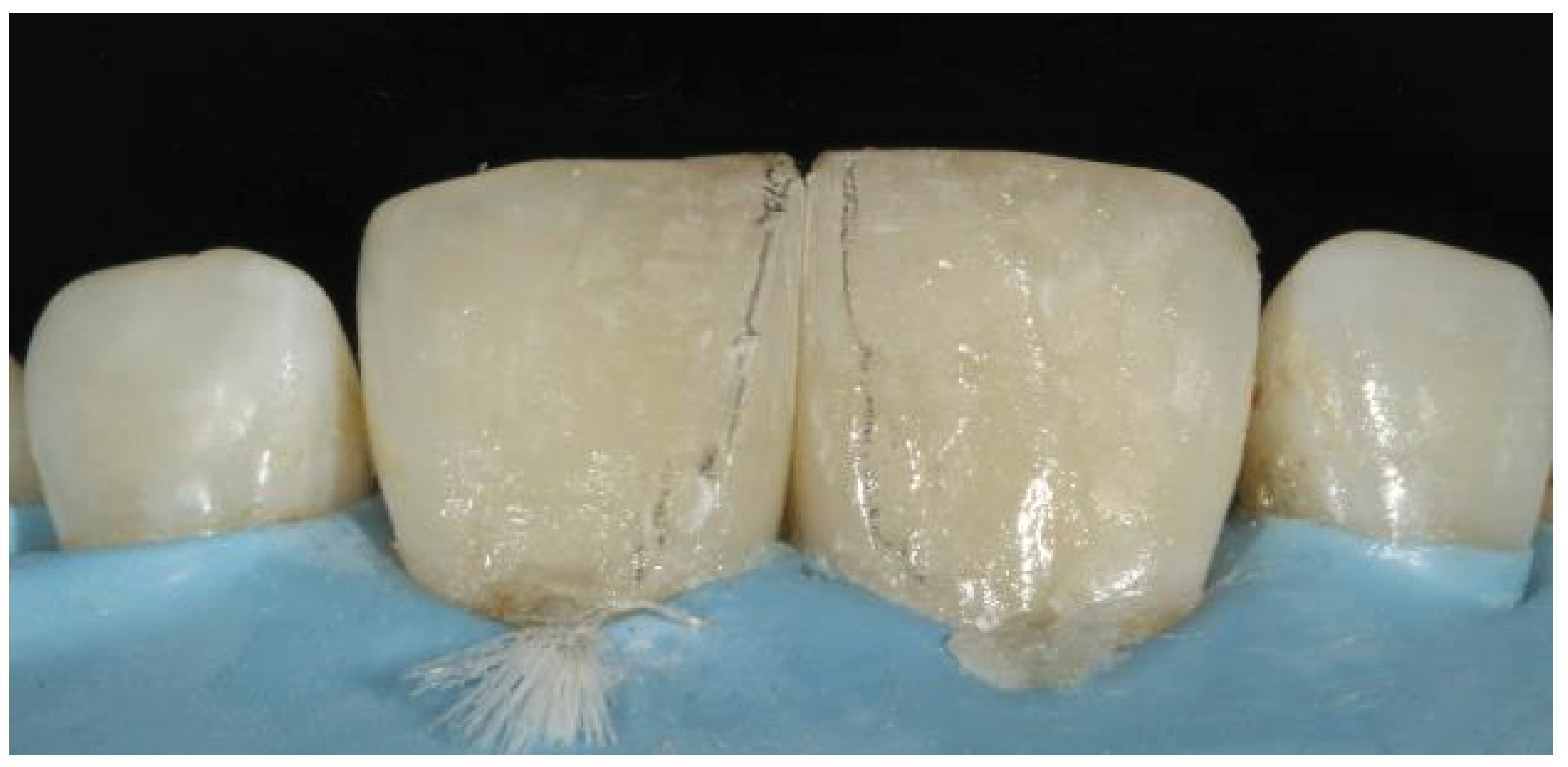
Figure 16.
Final outcome after the removal of the rubber dam.
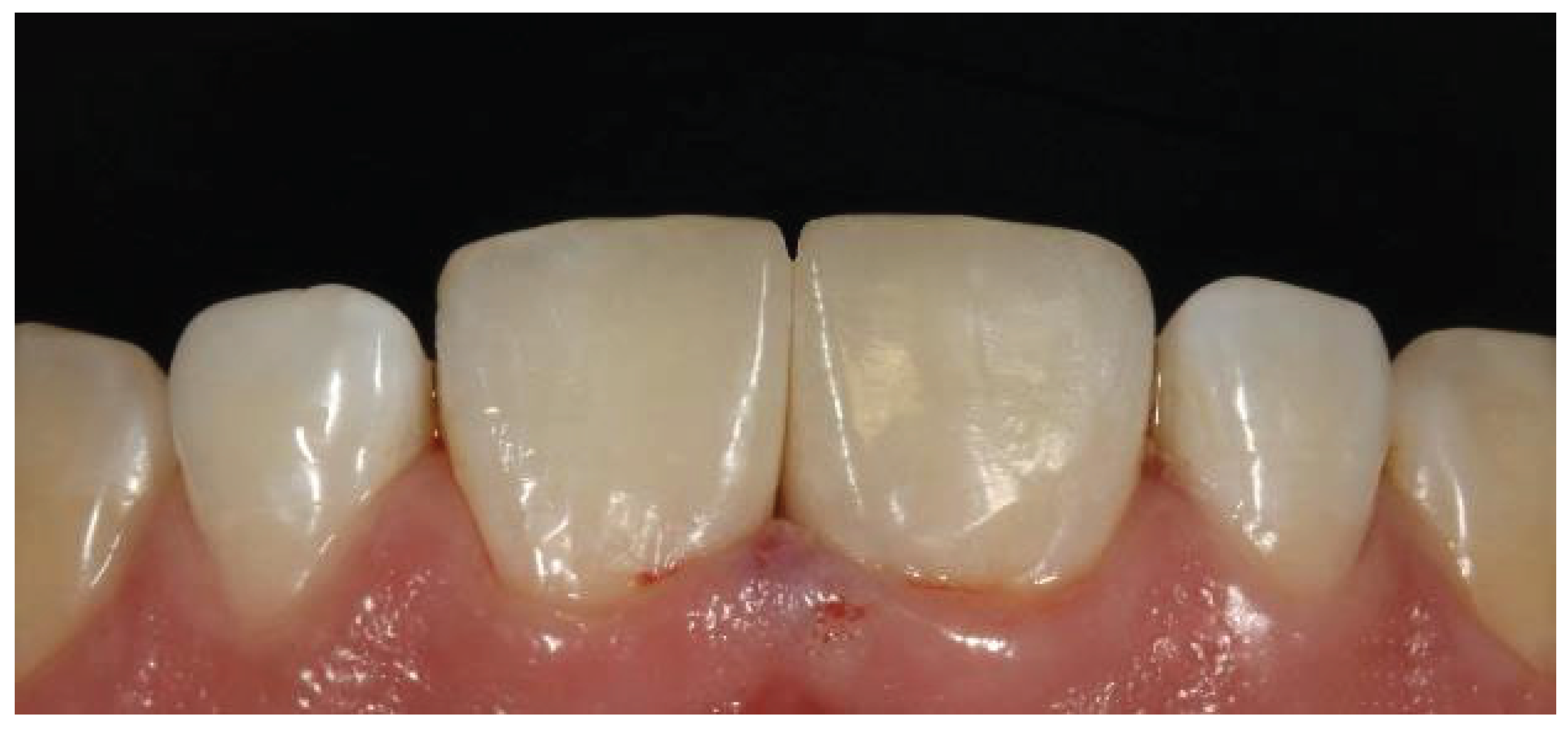
Figure 17.
Follow-up image after 2 years.
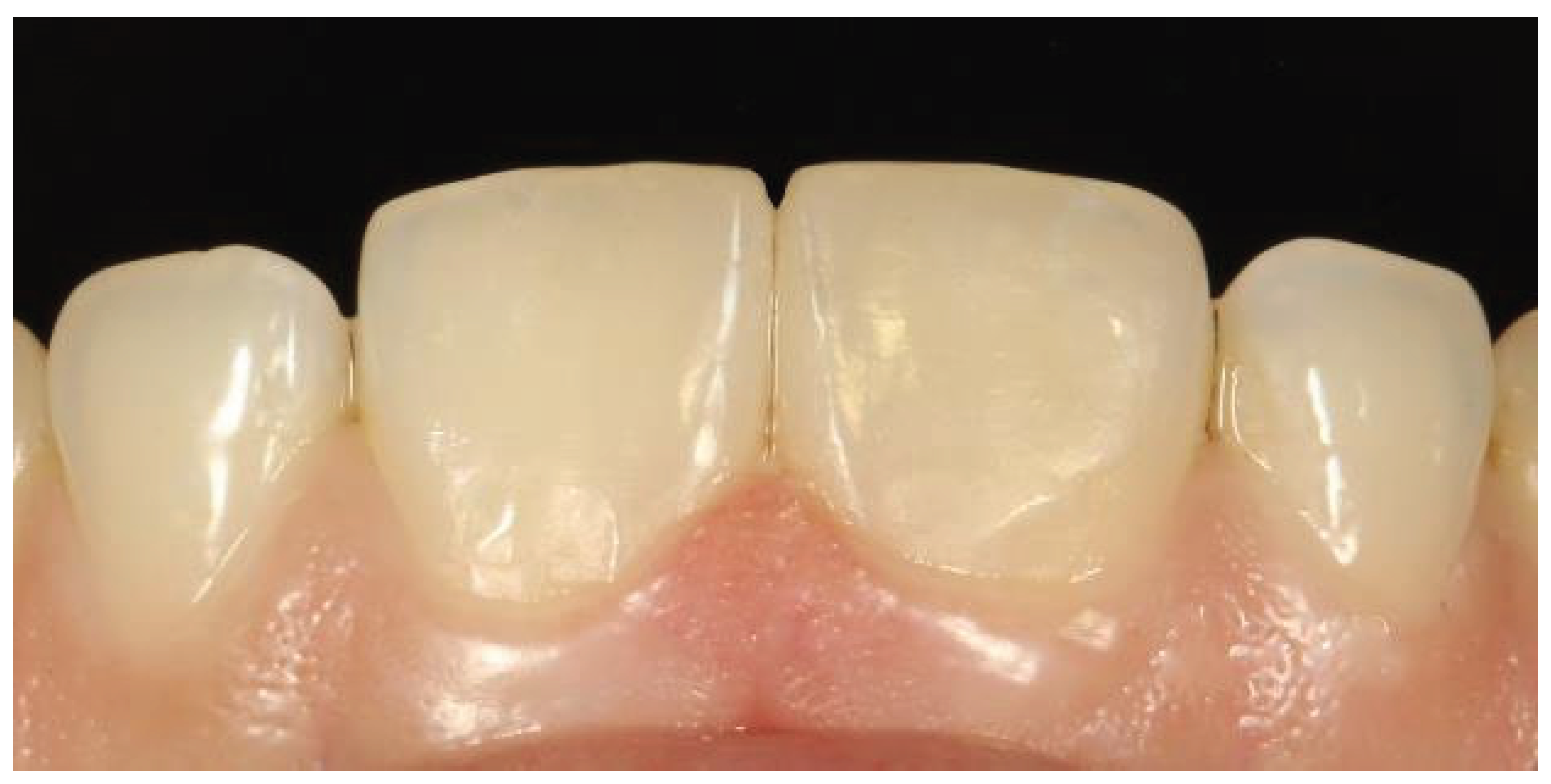
Figure 18.
Previously restored teeth showing mismatched shade.
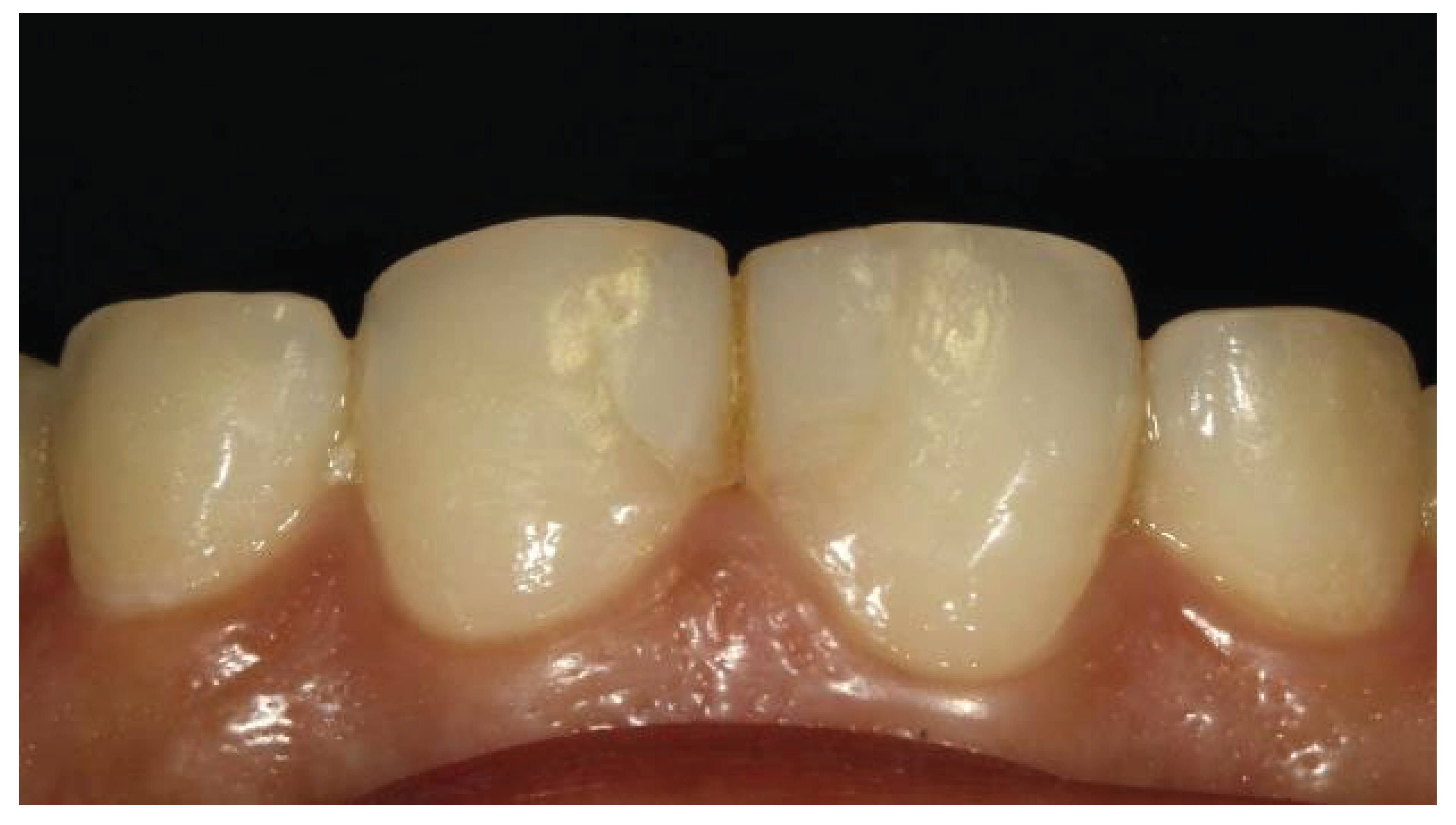
Figure 19.
Application of a rubber dam with removal of the midline composite restoration.
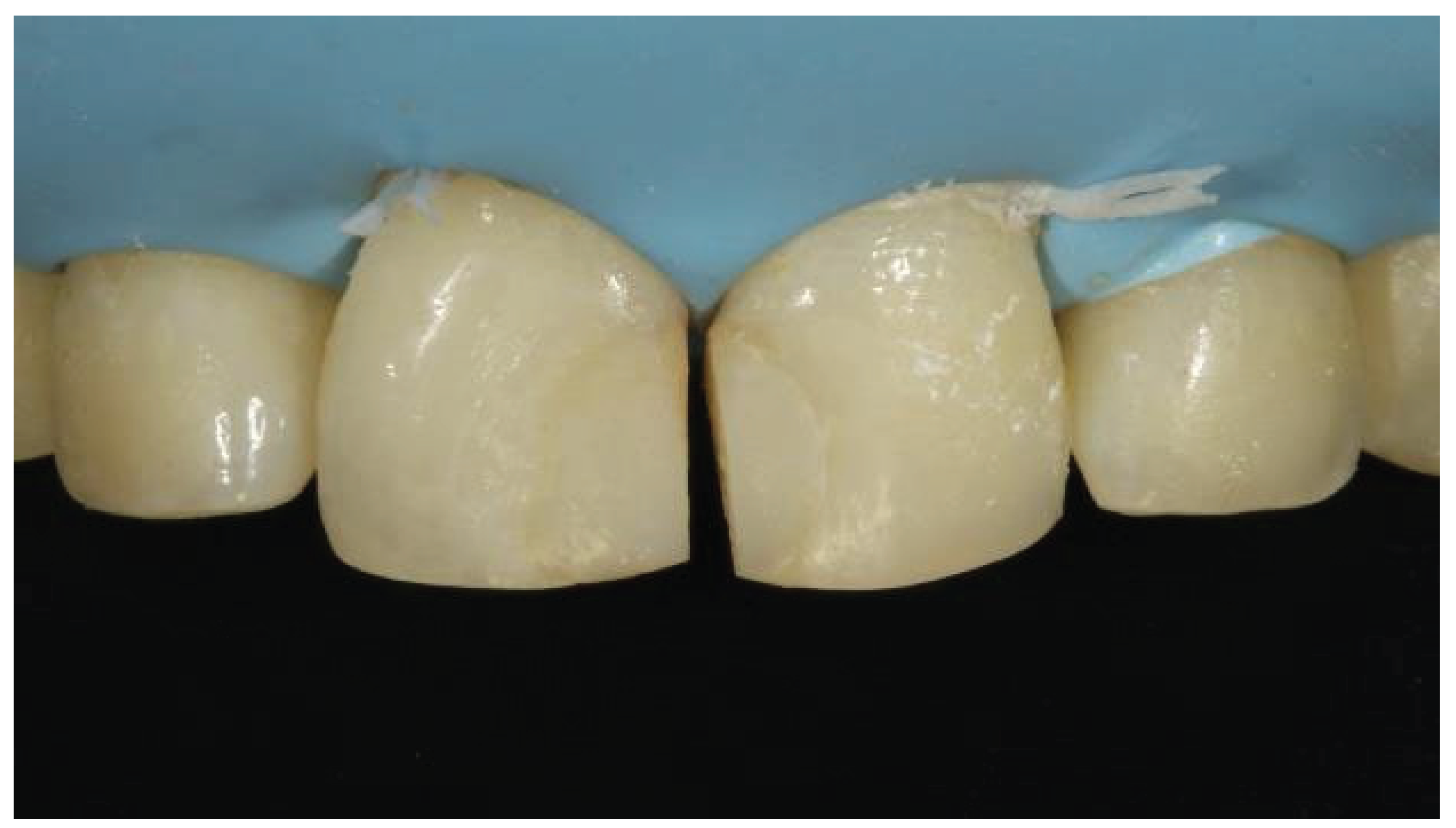
Figure 20.
Removal of old restorative material with enamel beveling.
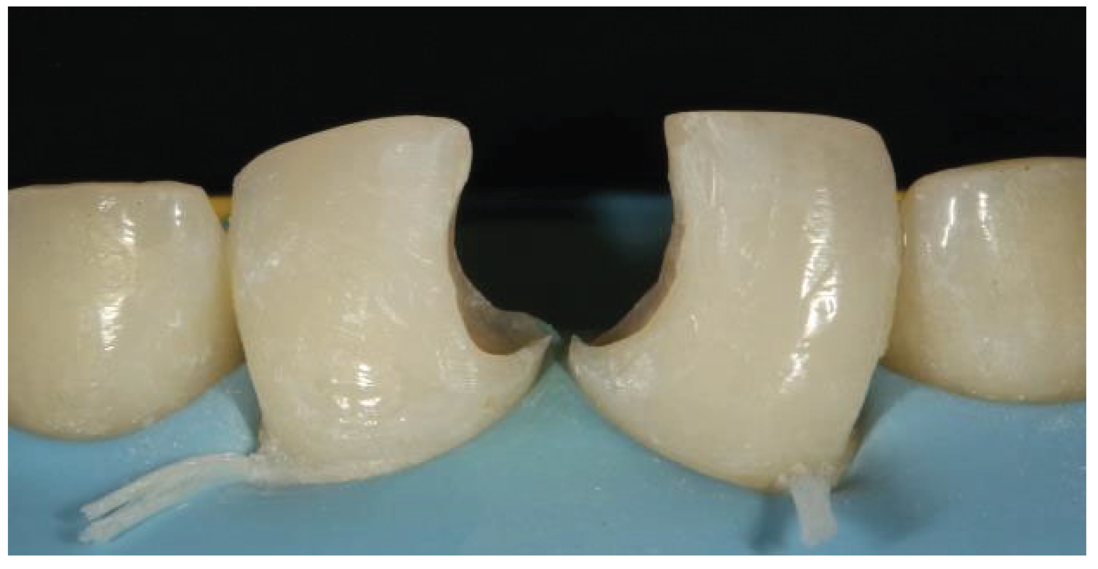
Figure 21.
Etching performed with 37% phosphoric acid.
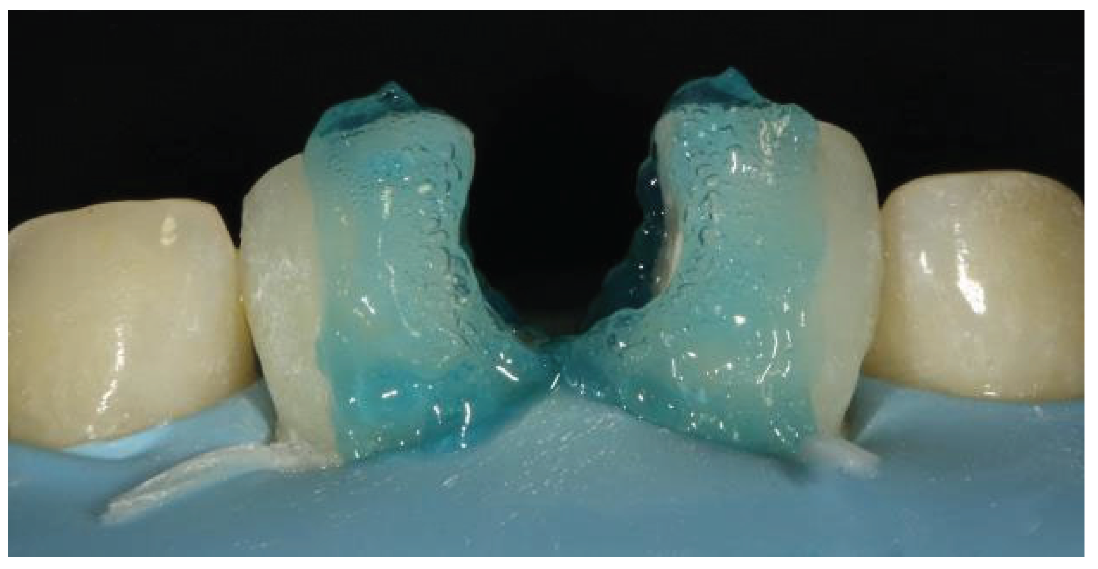
Figure 22.
Creation of the palatal shell with the help of a mylar strip.
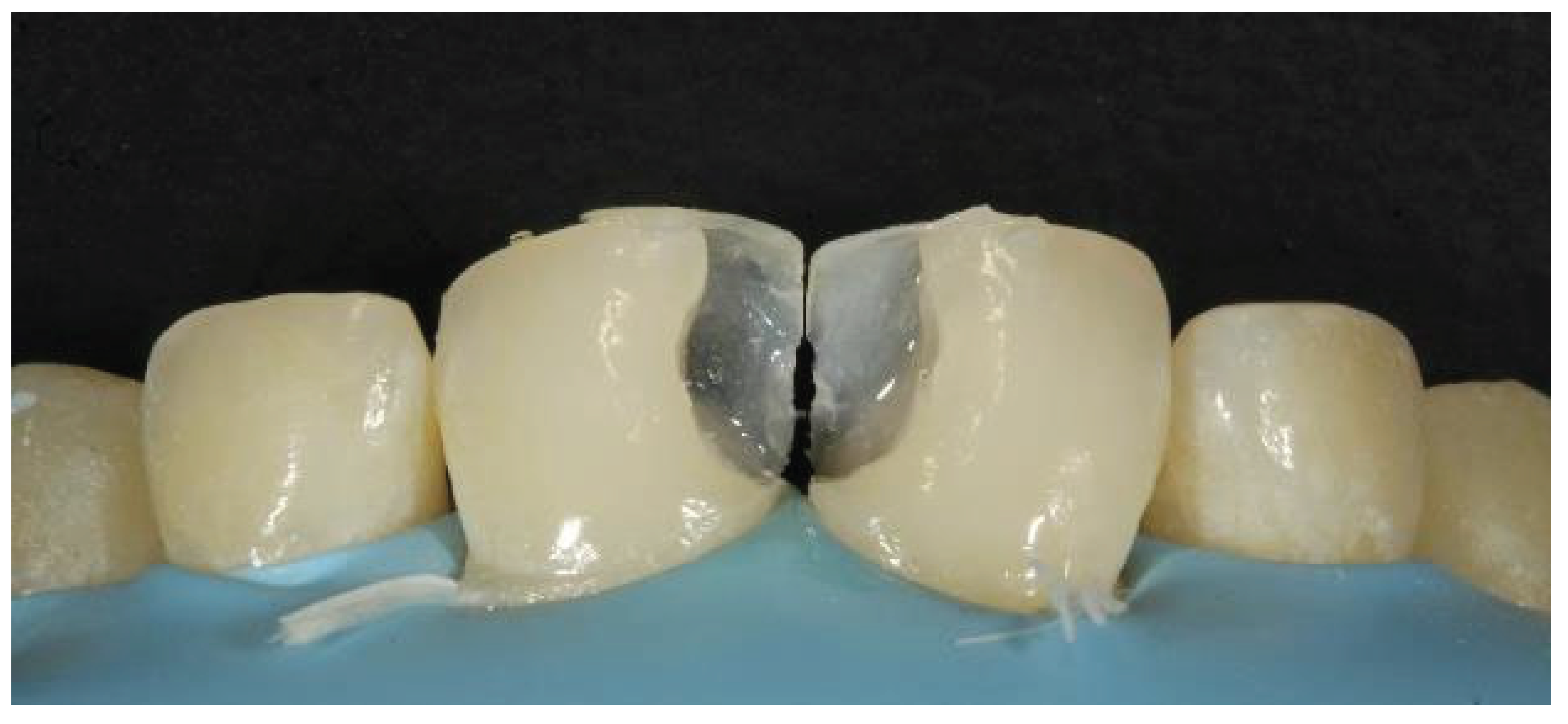
Figure 23.
Use of a sectional matrix for creating the proximal wall.
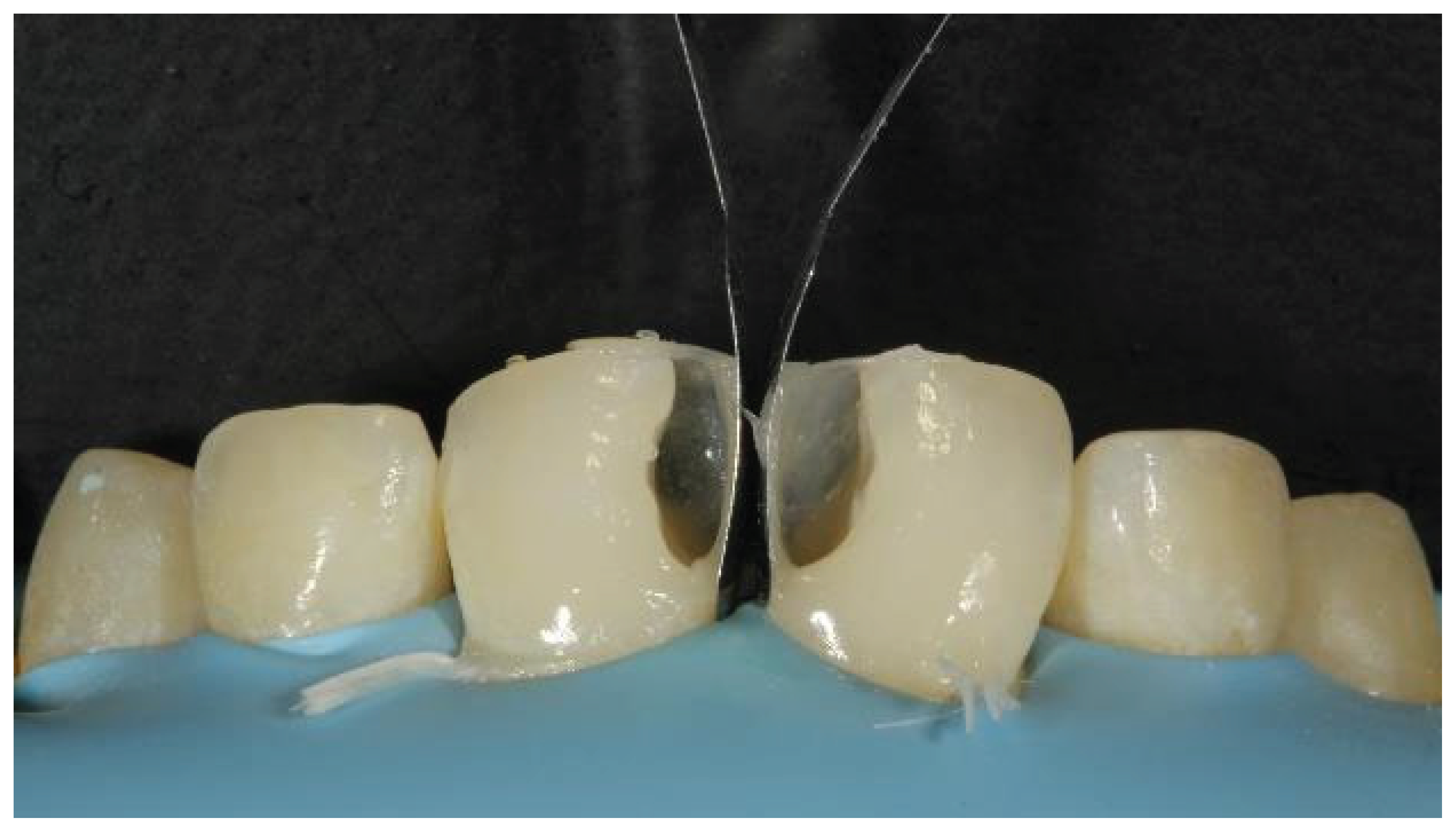
Figure 24.
Tooth contour created with a sectional matrix showing gaps in between.
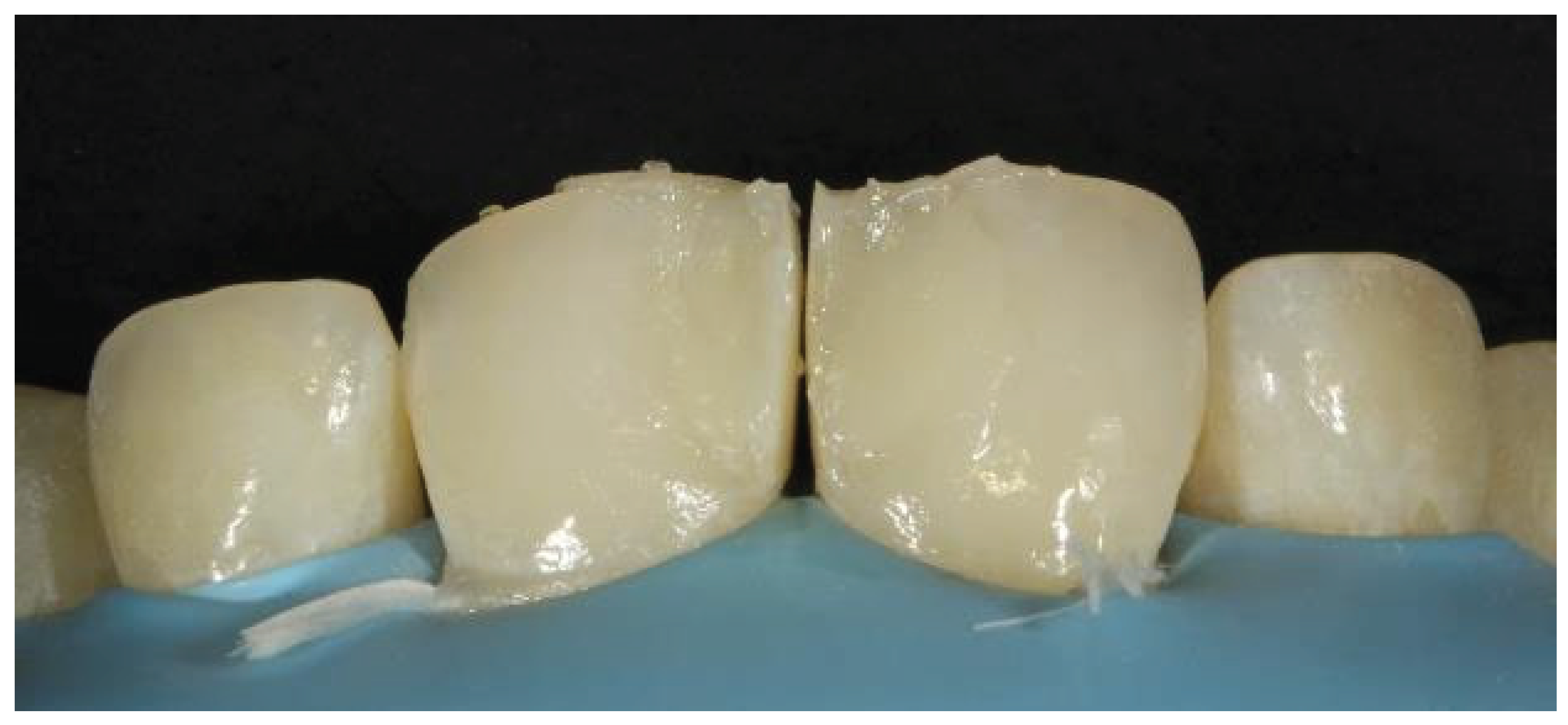
Figure 25.
Application of a dentin composite followed by an enamel composite.
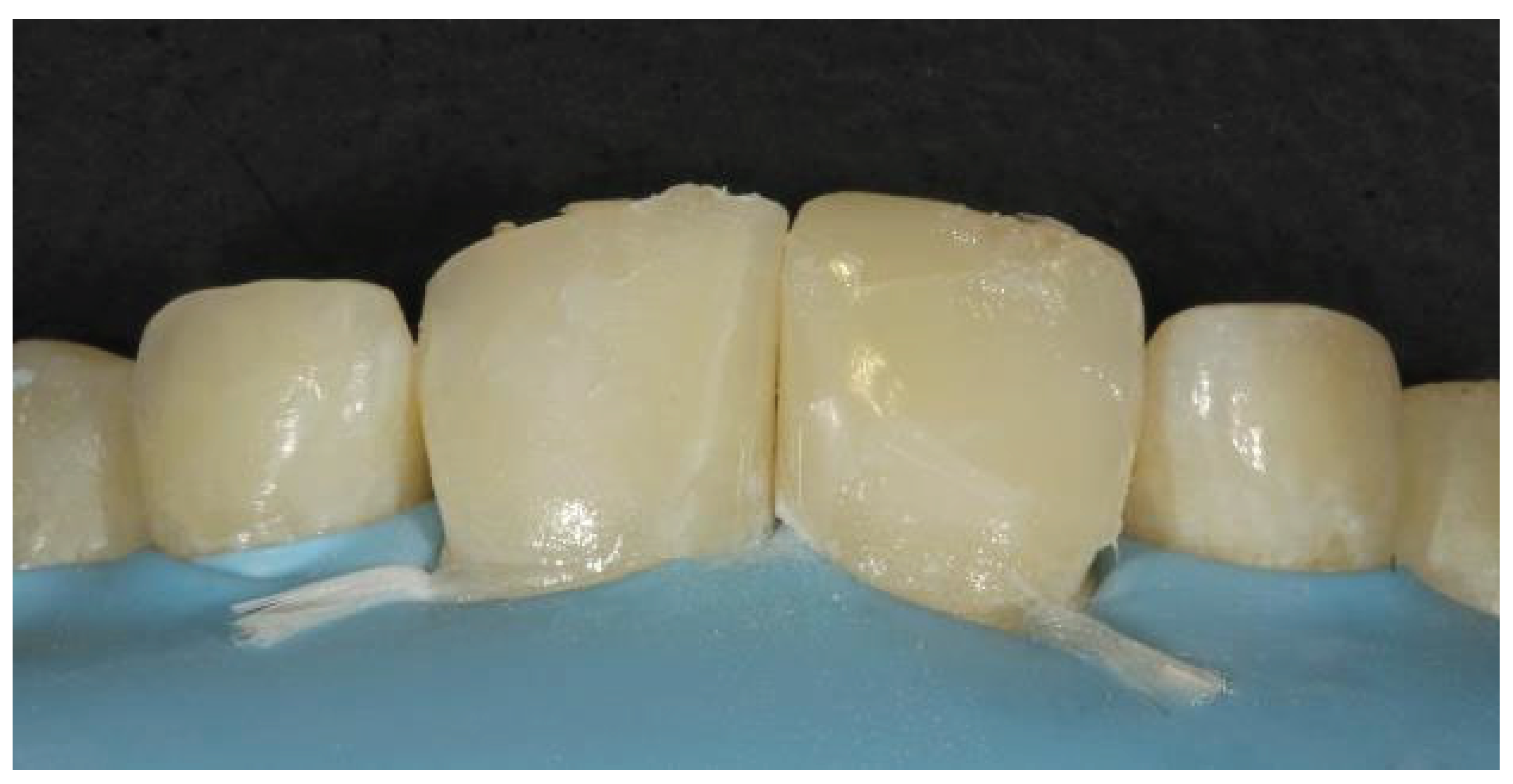
Figure 26.
Marking of line angles.
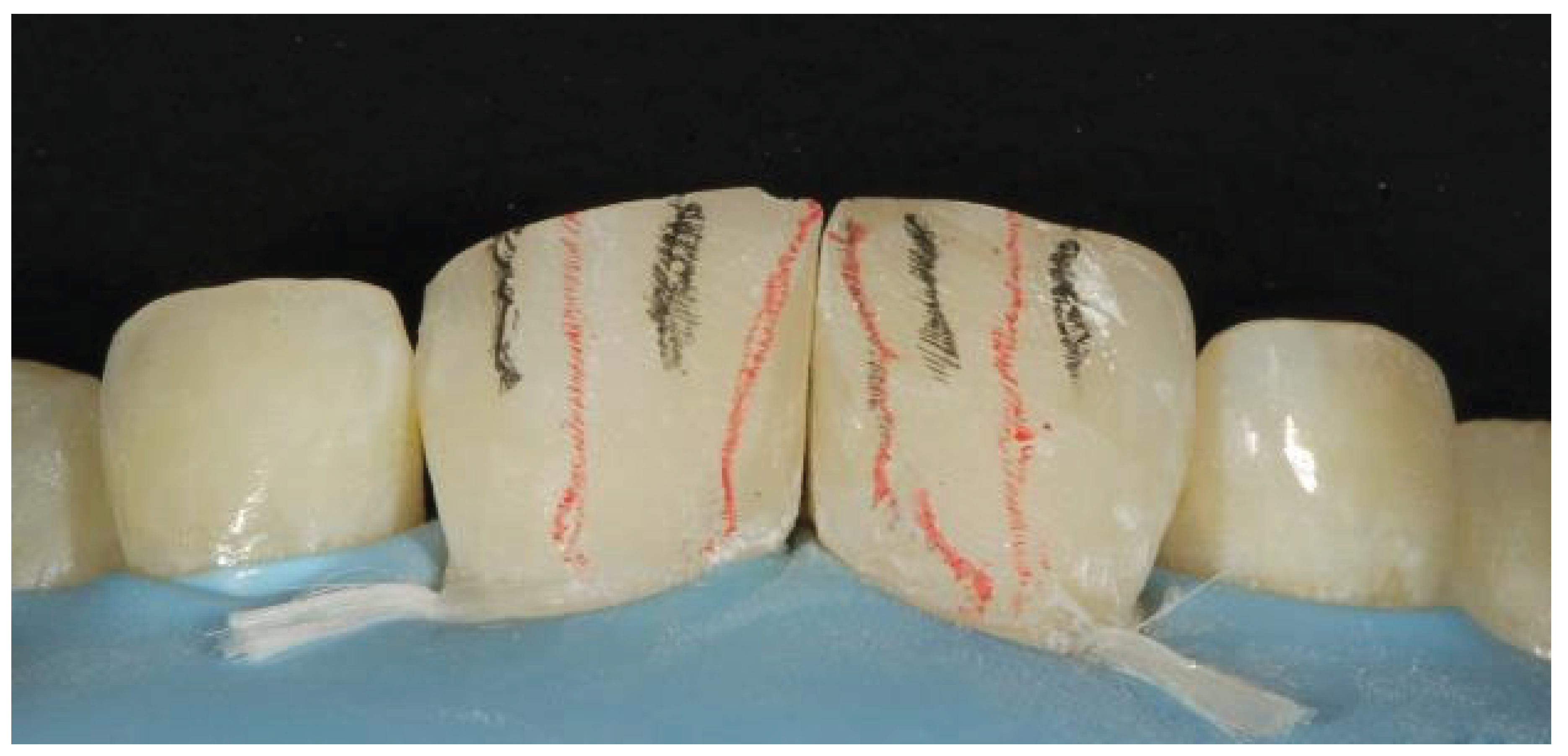
Figure 27.
Final outcome after the removal of the rubber dam.
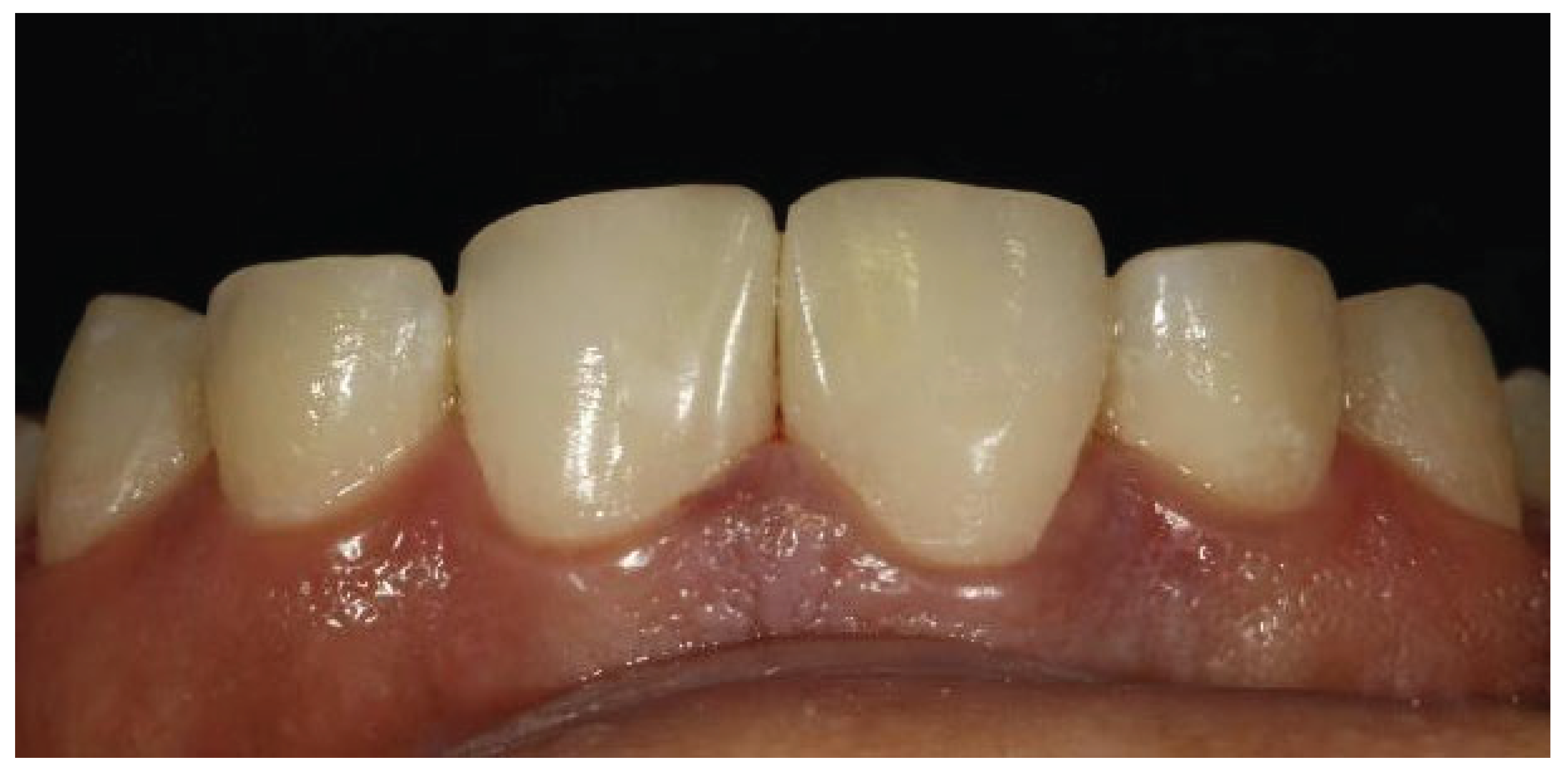
Figure 28.
Preoperative image showing a fractured restoration with poor aesthetics.
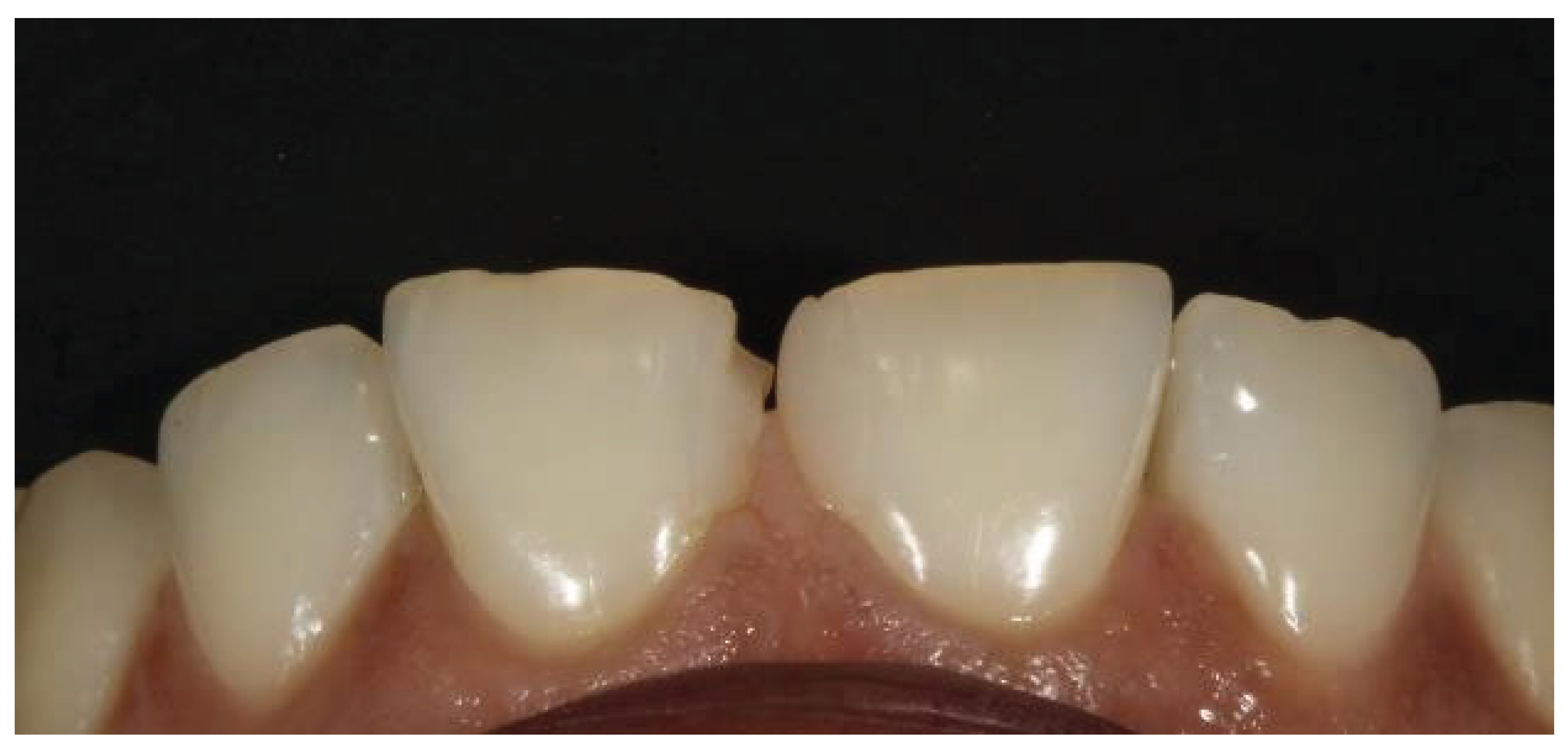
Figure 29.
Shade selection.
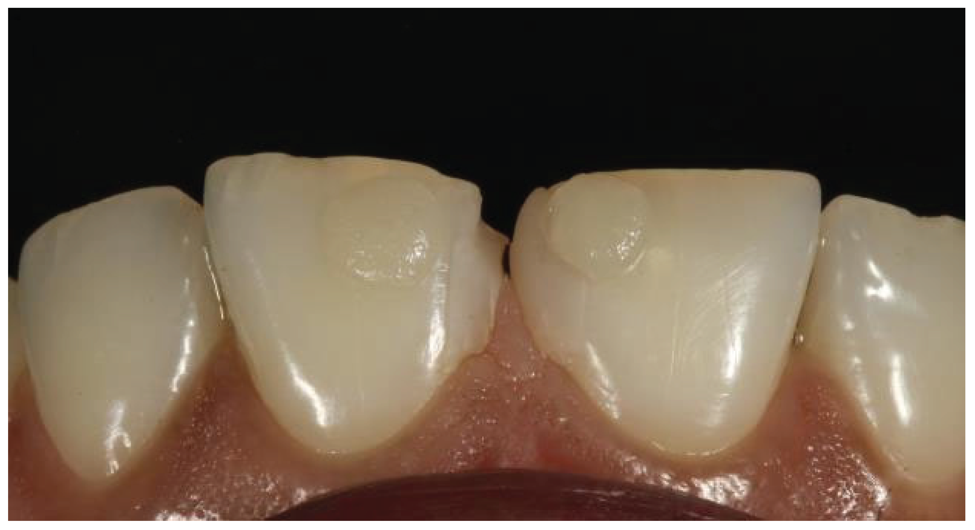
Figure 30.
Application of the rubber dam.
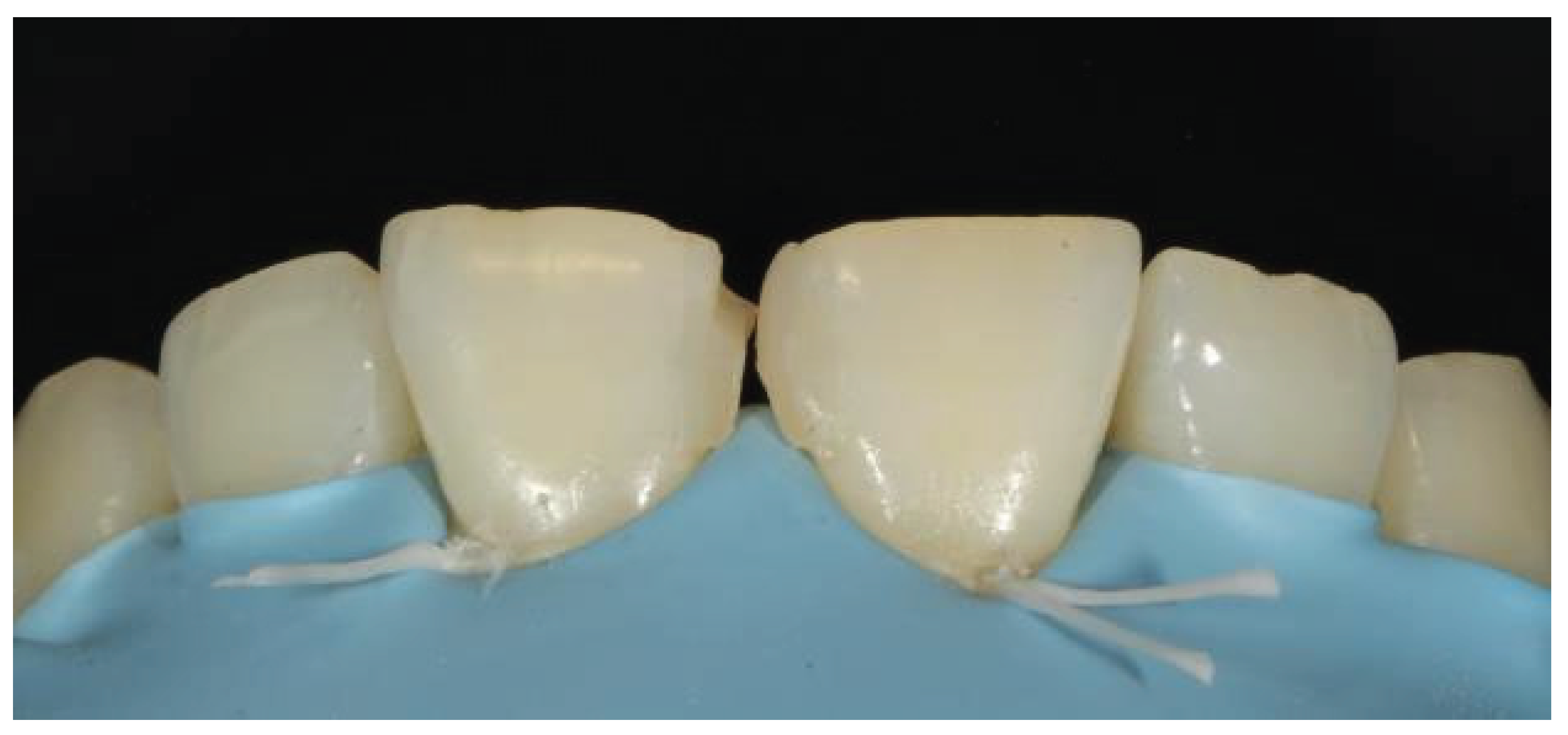
Figure 31.
After removal of the old restoration.
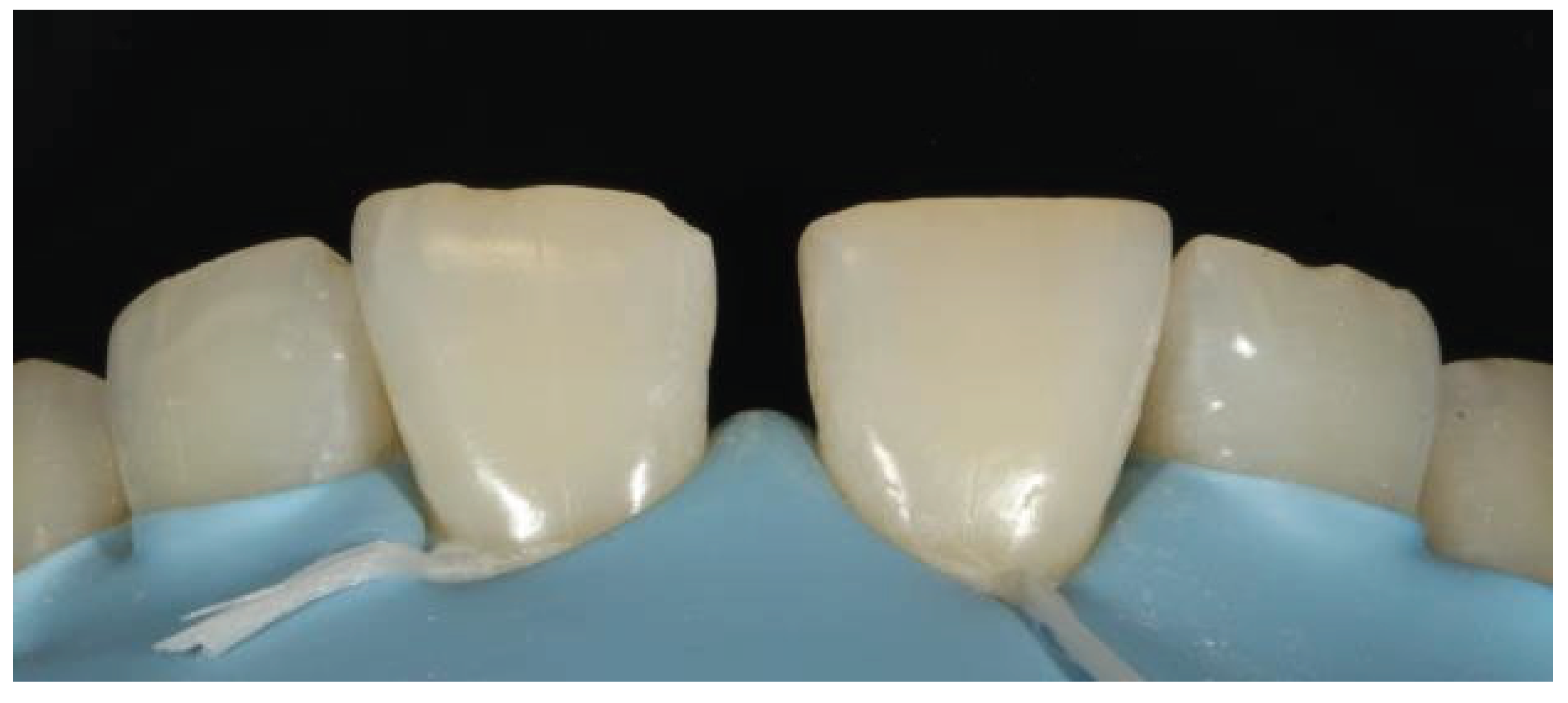
Figure 32.
Application of the etchant.
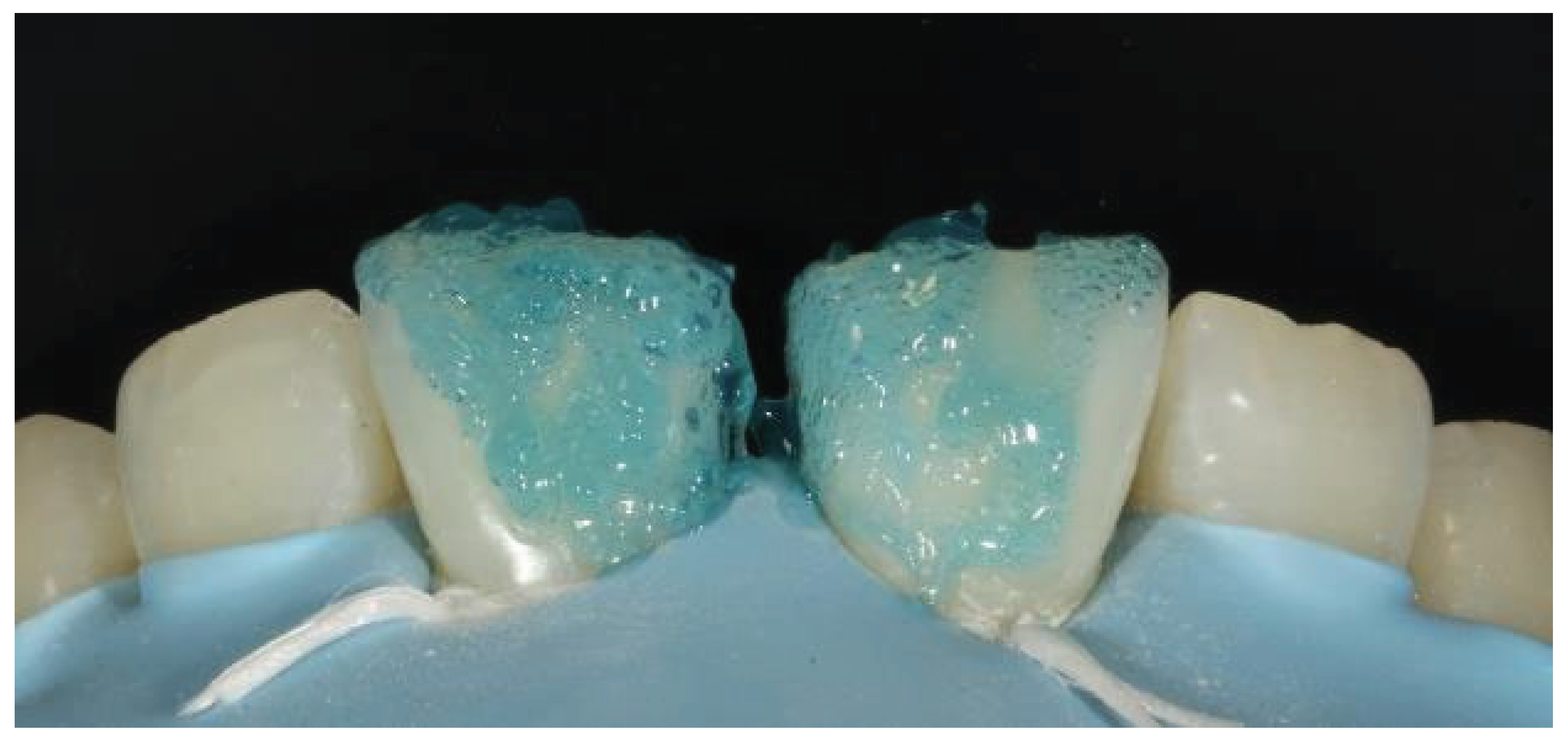
Figure 33.
Incisal edge made with a Mylar strip.
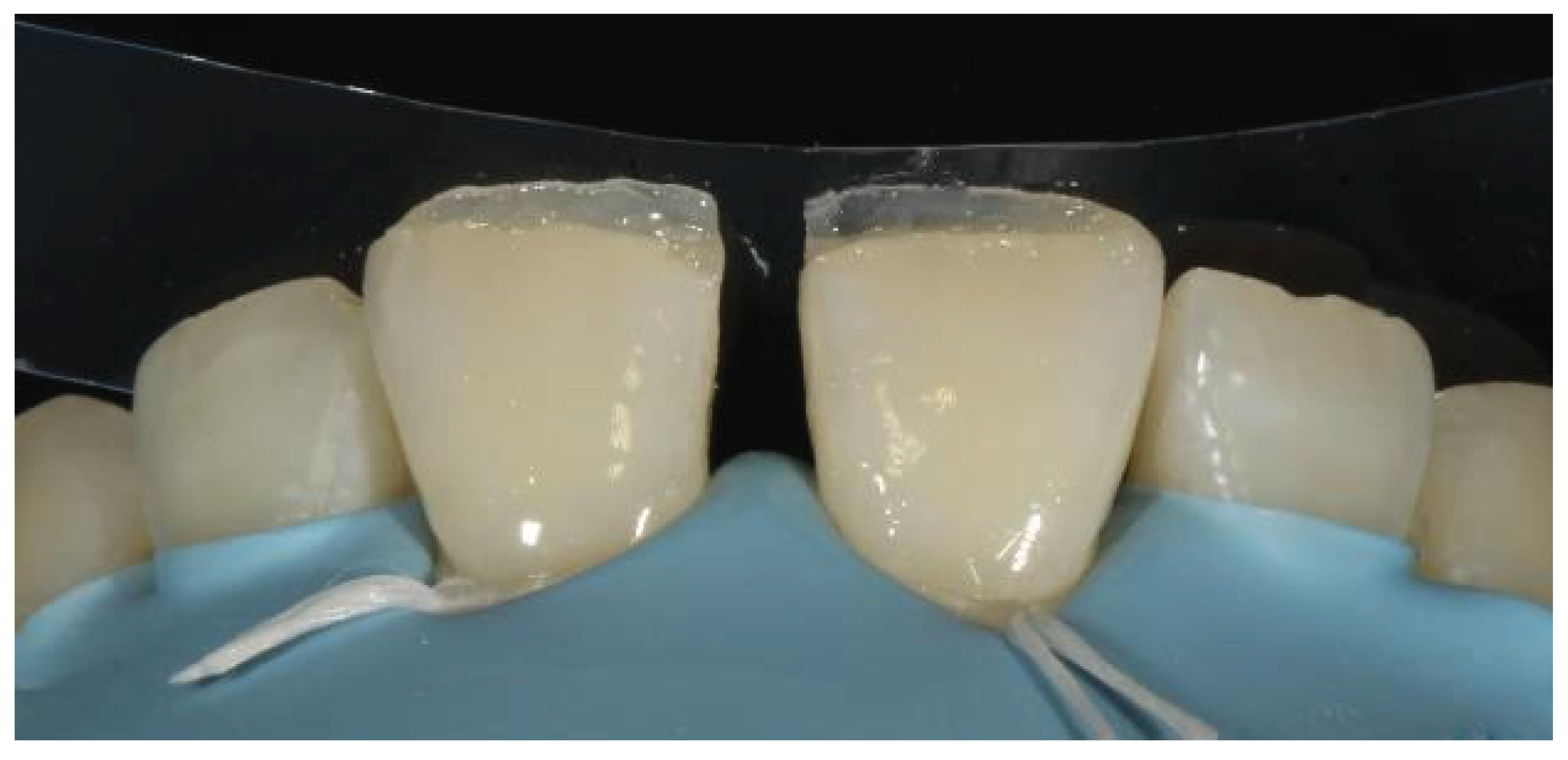
Figure 34.
Positioning of the bioclear matrices.
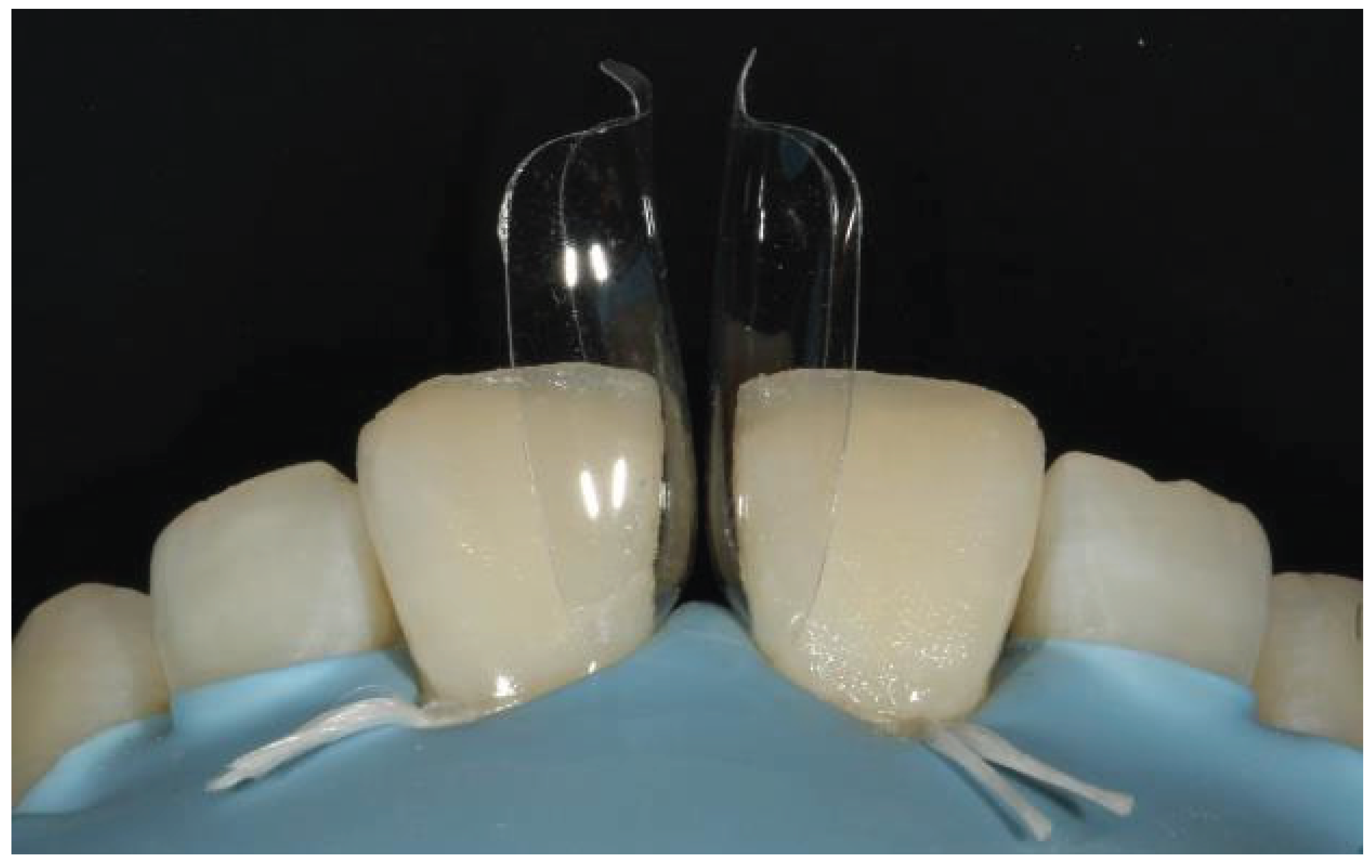
Figure 35.
Filling of the cervical region with the flowable composite.
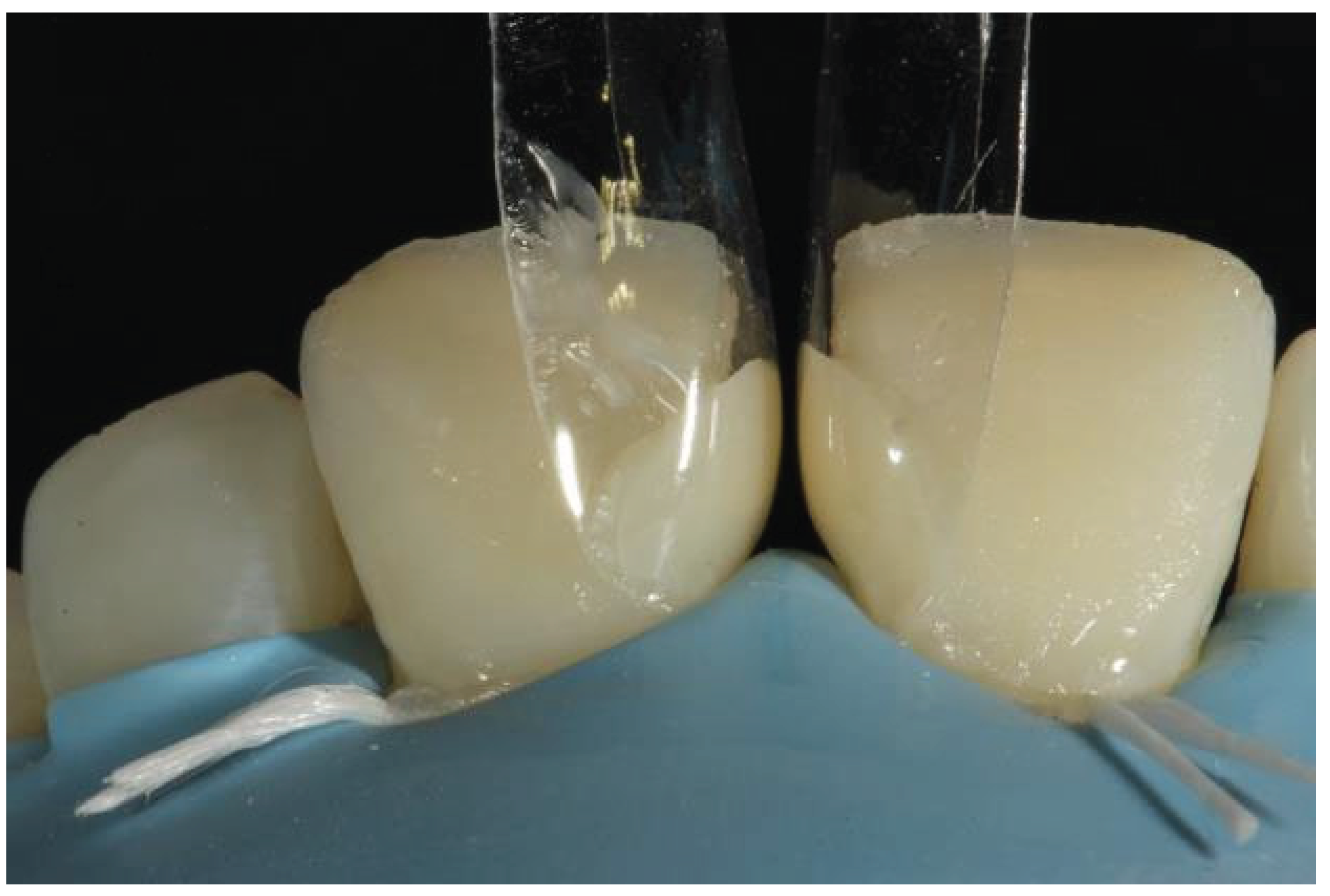
Figure 36.
Tooth contour after removal of the bioclear matrices.
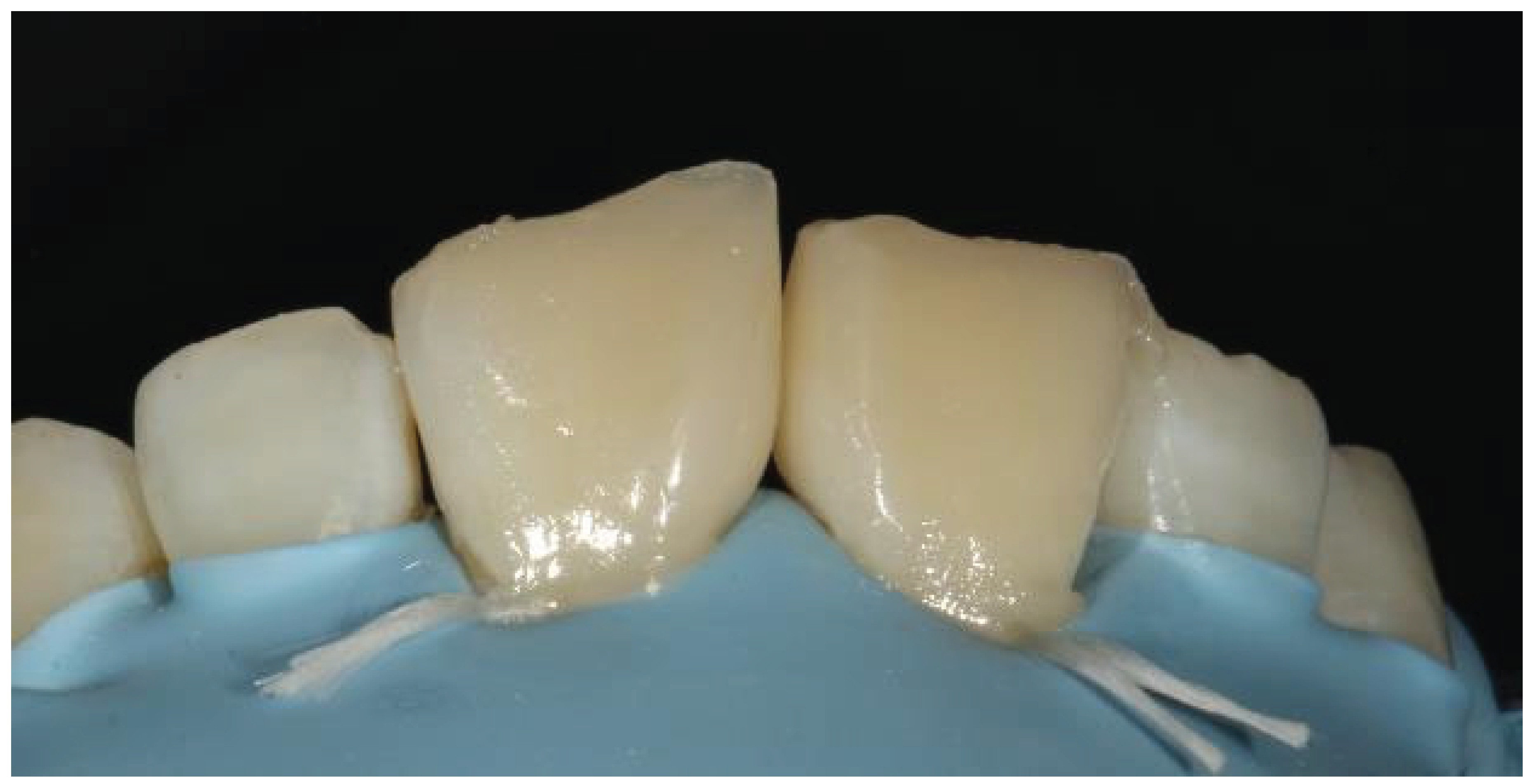
Figure 37.
Marking of line angles.
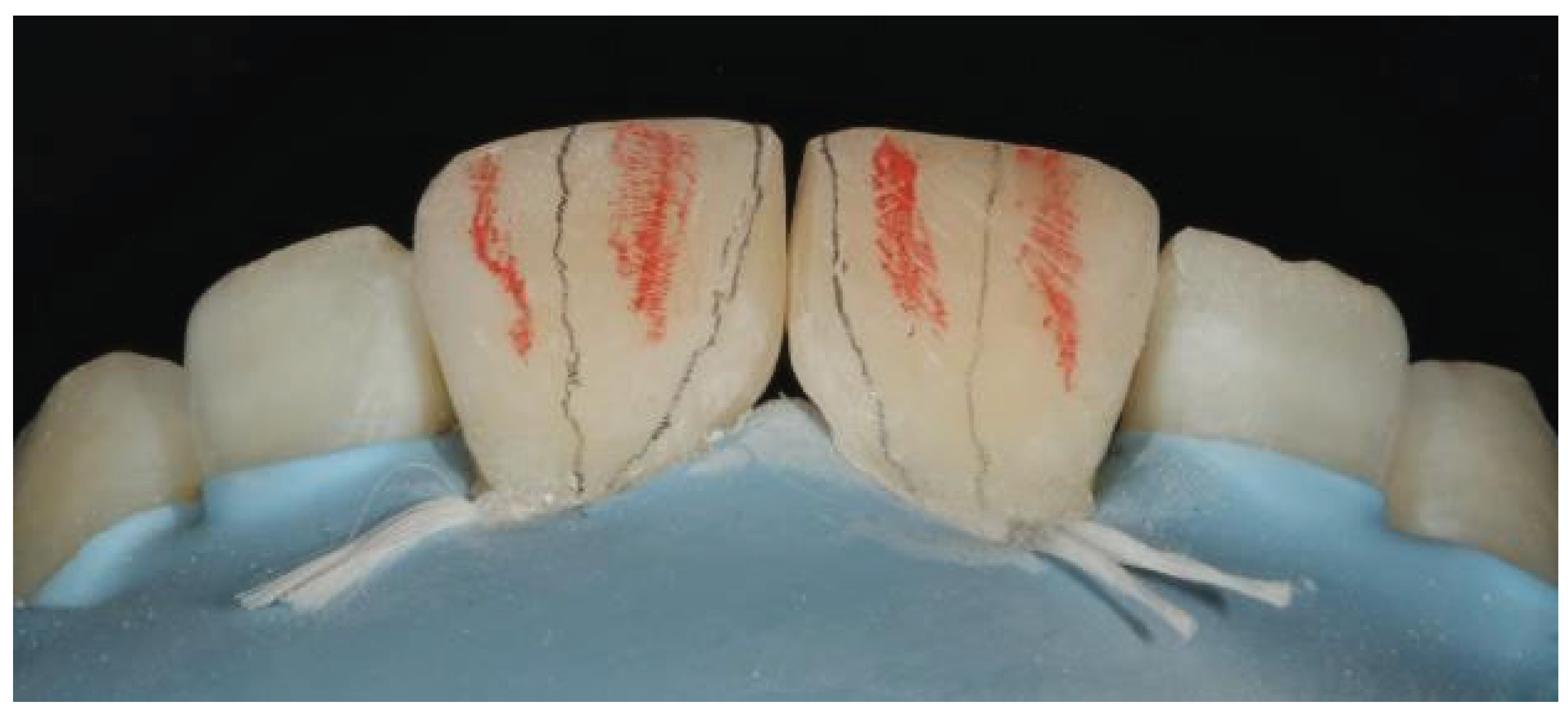
Figure 38.
Finished restorations with discs and burs.
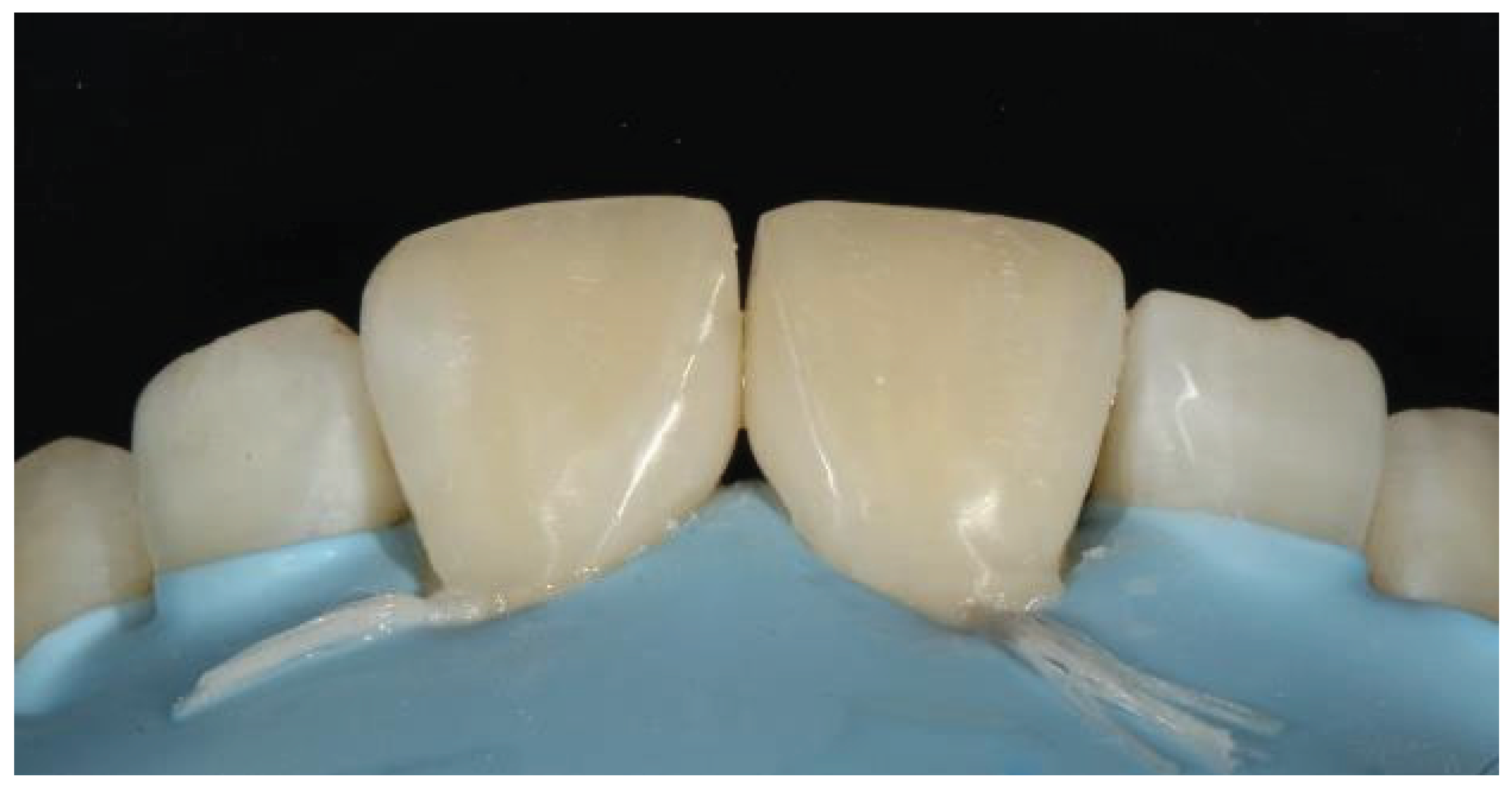
Figure 39.
Final results after the removal of the rubber dam.
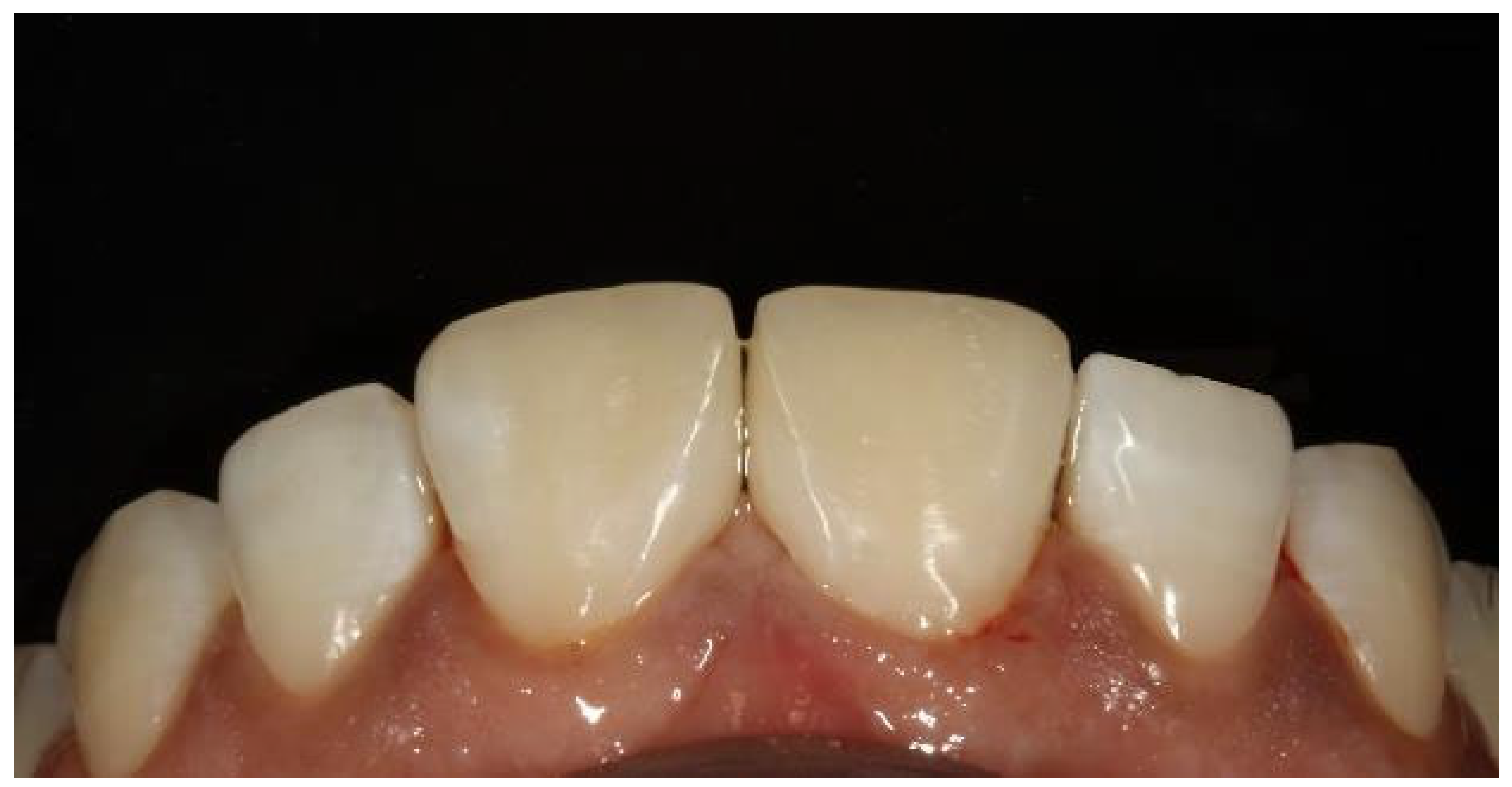
Figure 40.
Clinical image showing midline diastema.
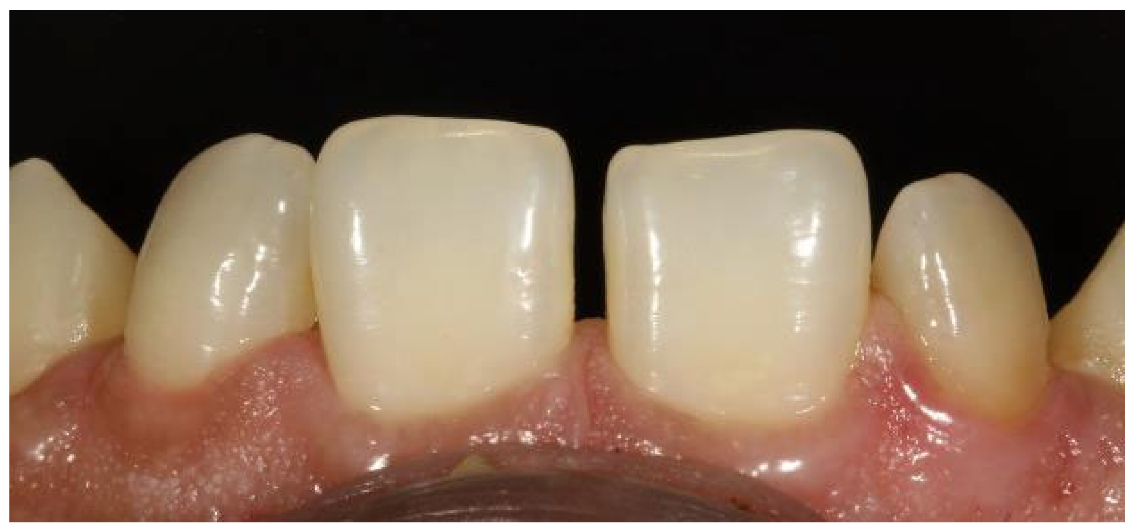
Figure 41.
Ethching after isolation with a rubber dam.
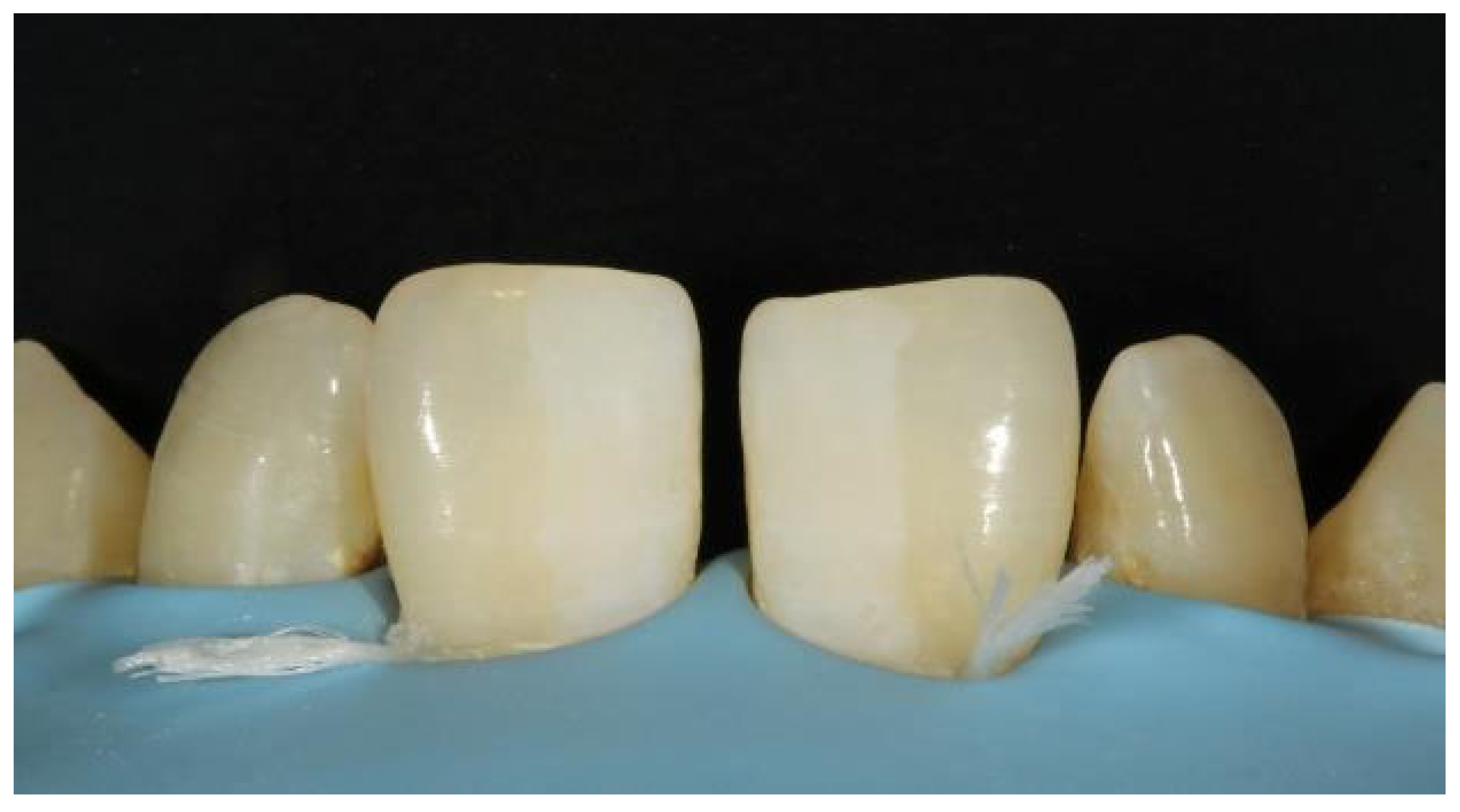
Figure 42.
Improper contact even after placement of the Bioclear matrices.
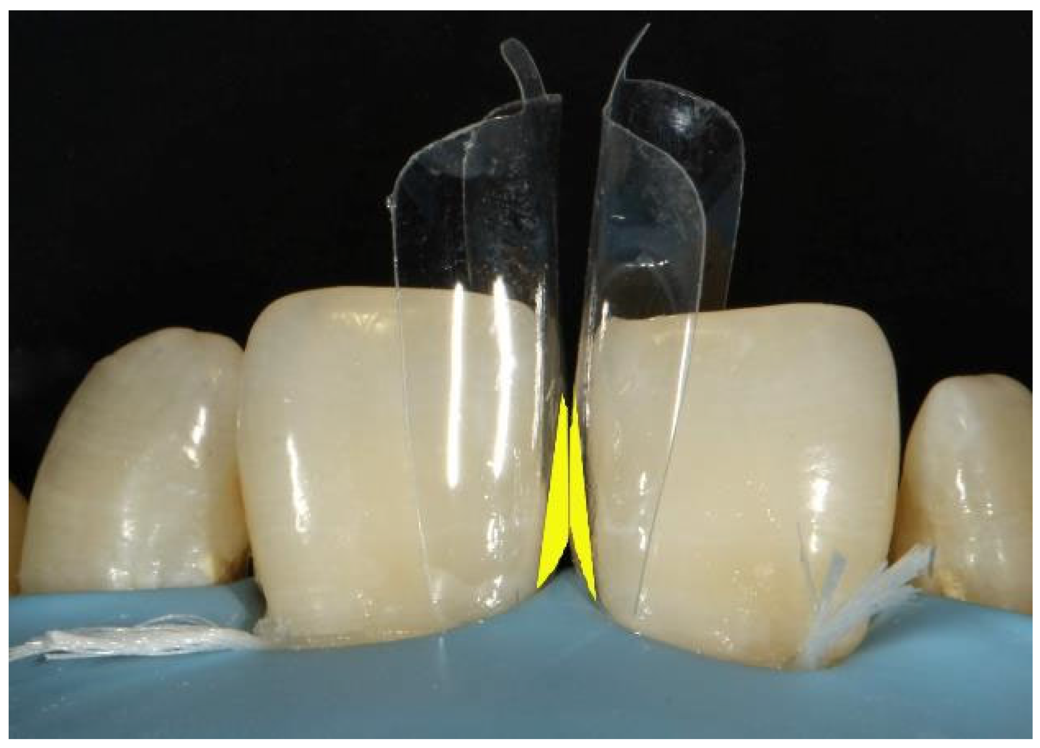
Figure 43.
Planning for creating the palatal shell.
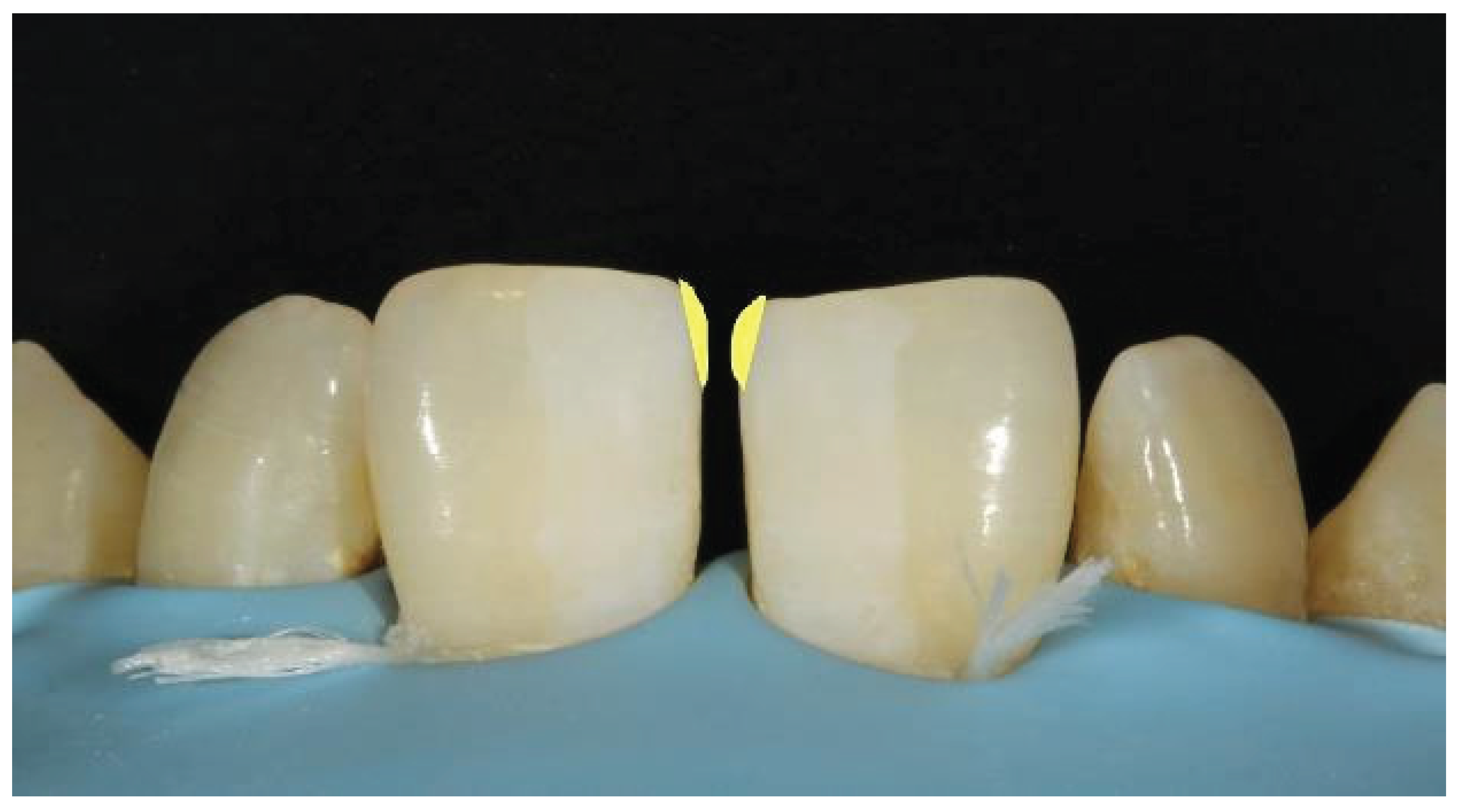
Figure 44.
Palatal shell extending toward the midline, supporting a bioclear matrix.
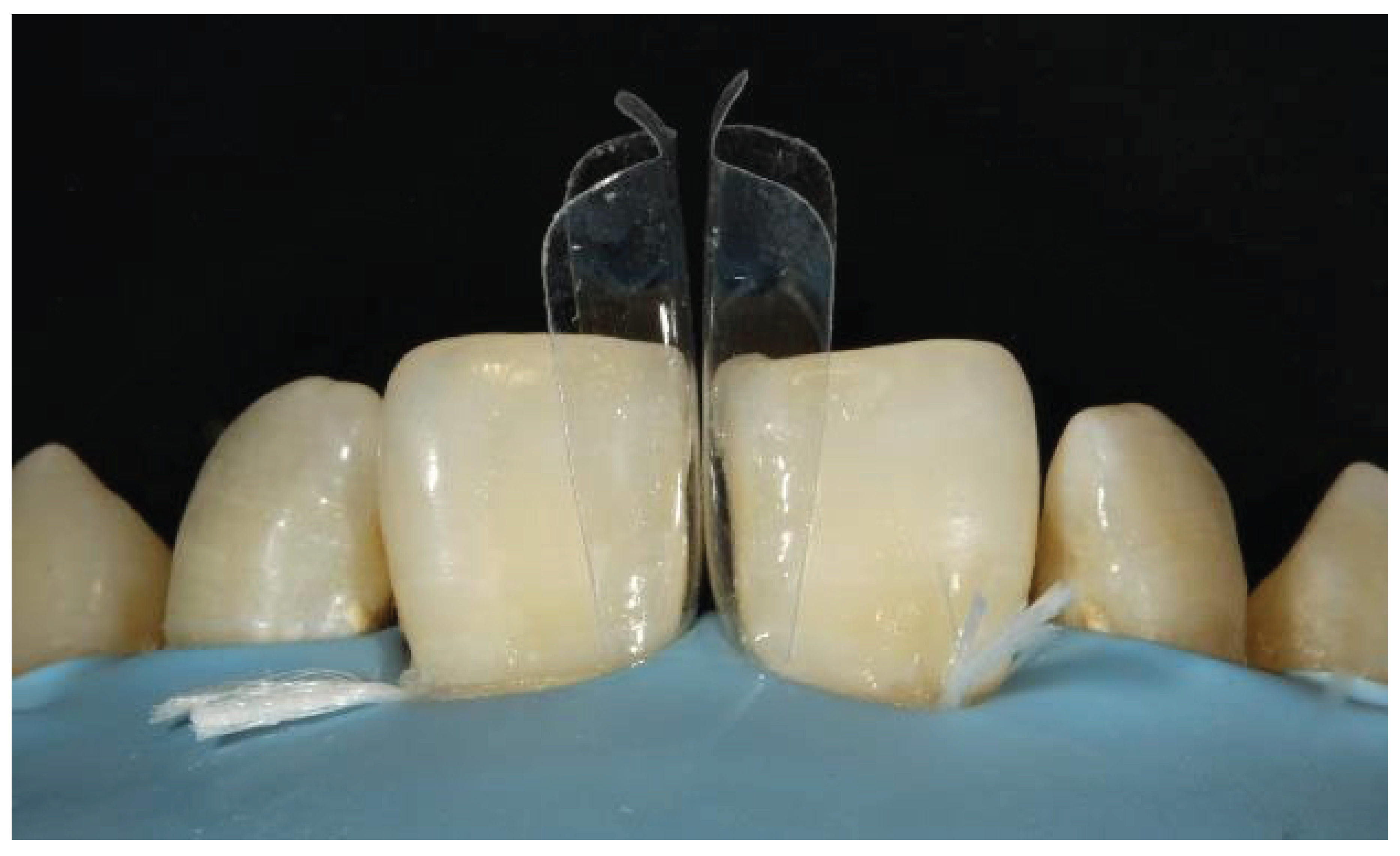
Figure 45.
Cervical region filled with flowable composite.
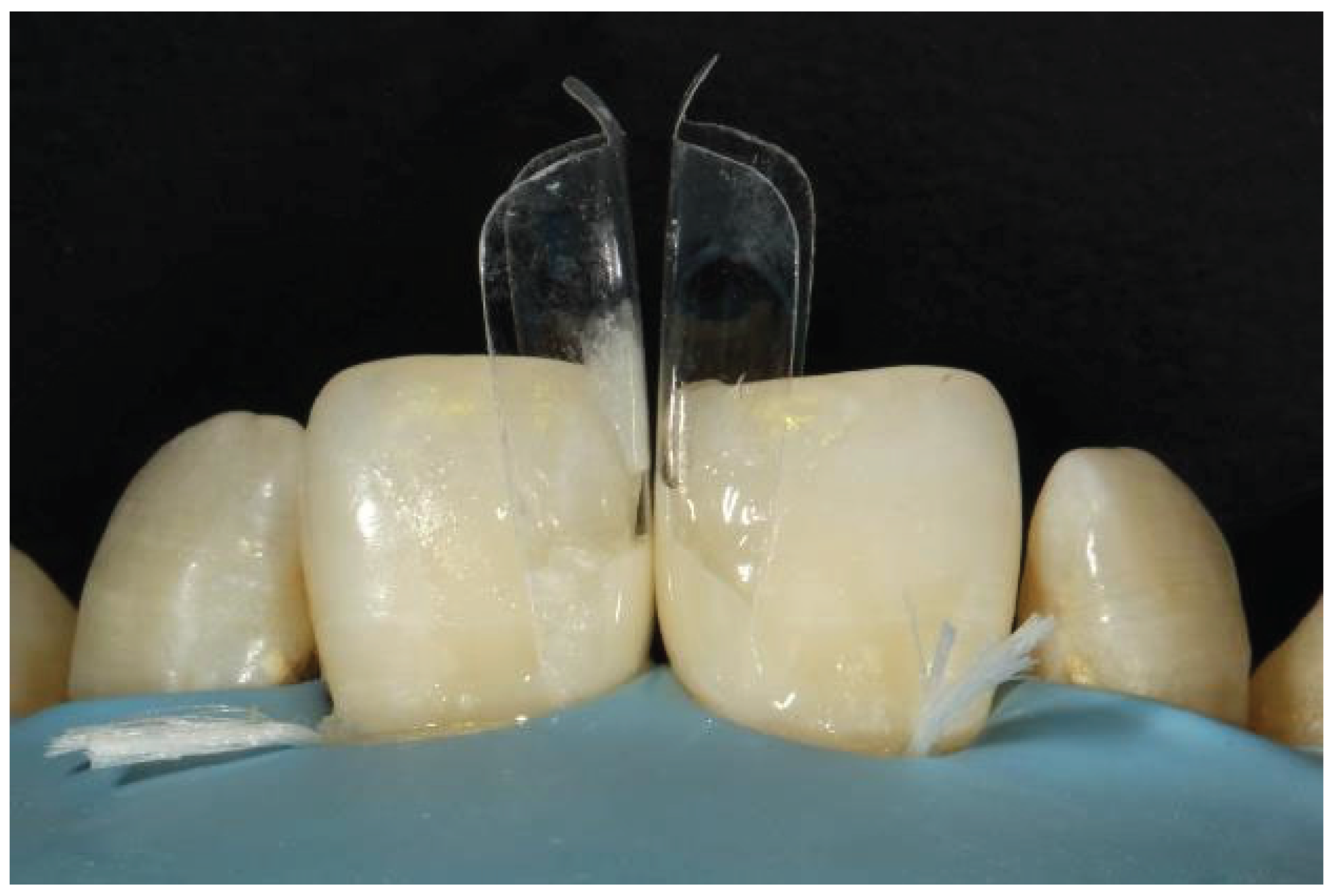
Figure 46.
Restoration after removing the bioclear matrices.
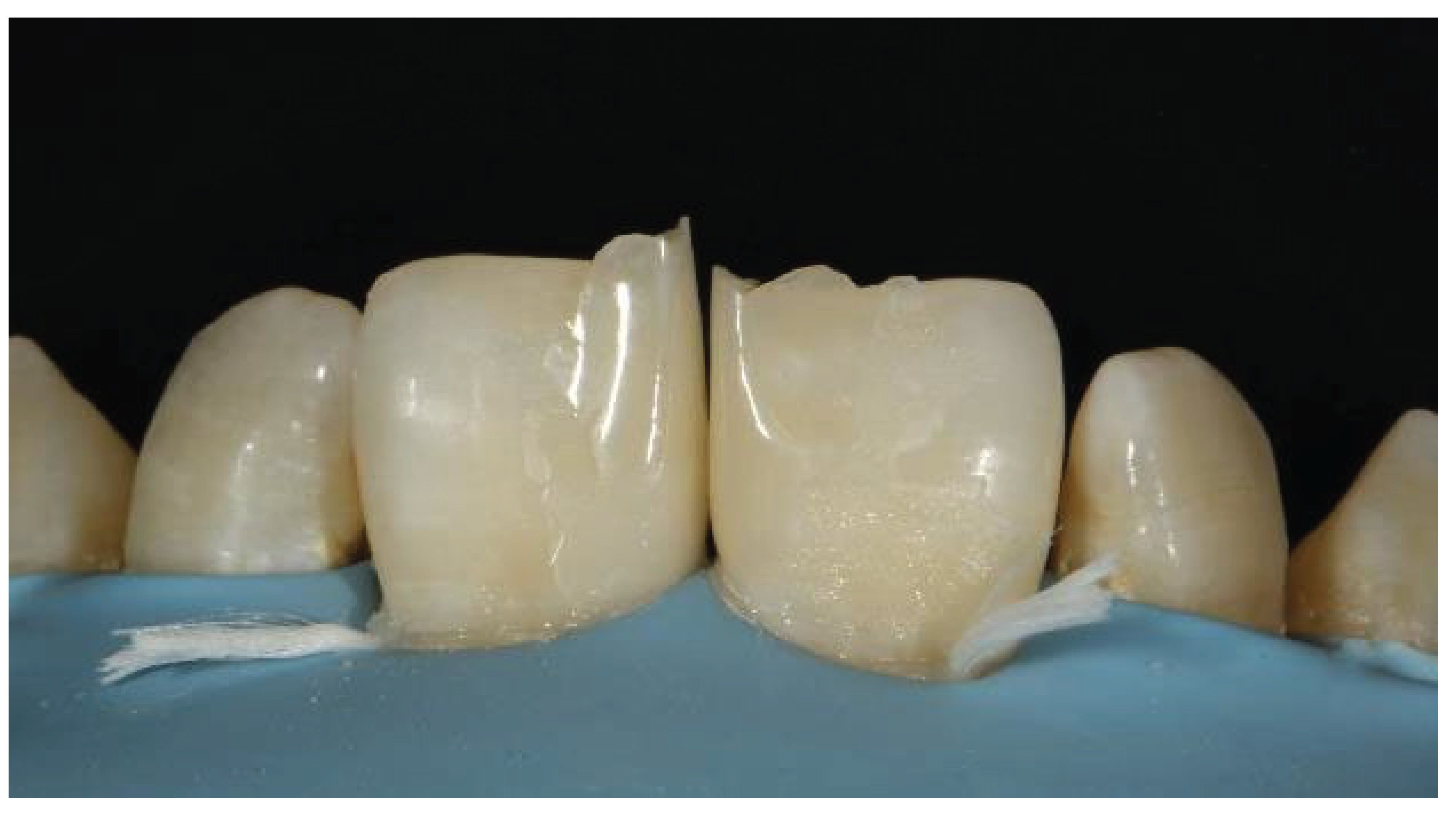
Figure 47.
Marking of line angles.
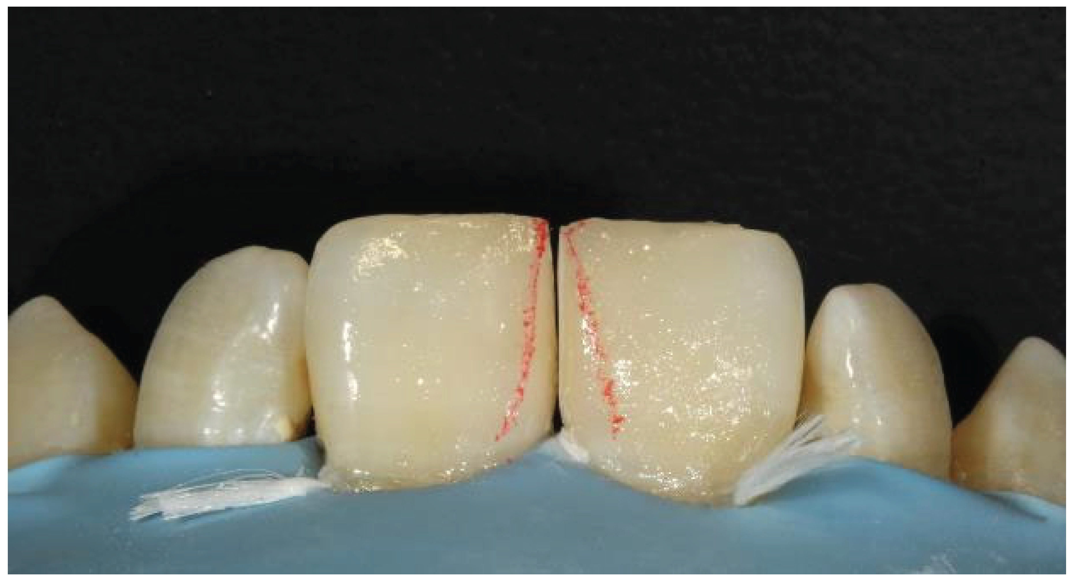
Figure 48.
After finishing and polishing.
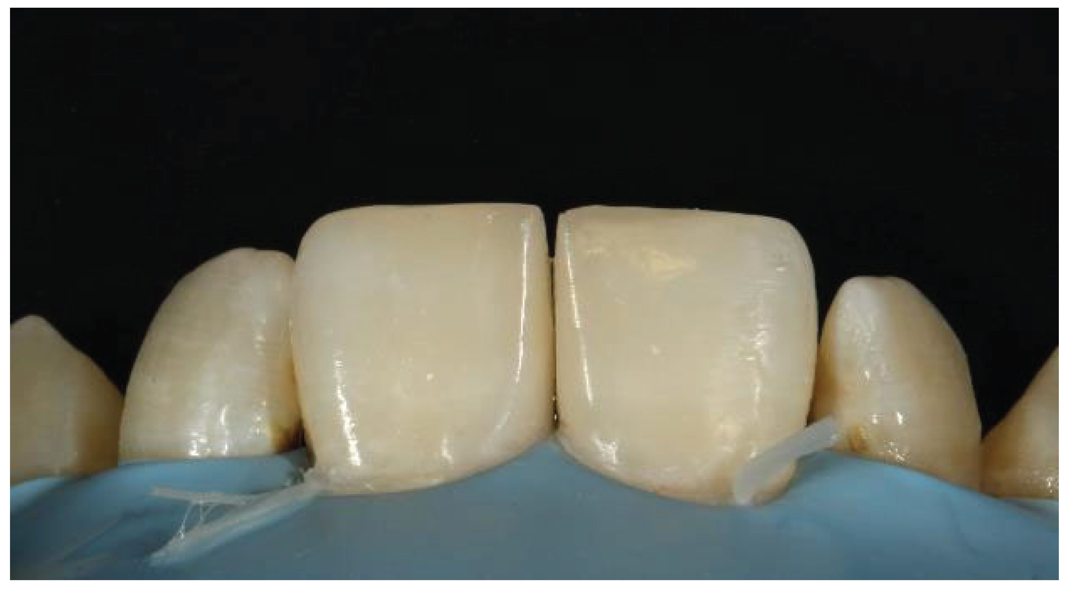
Figure 49.
Final outcome showing aesthetic restoration.
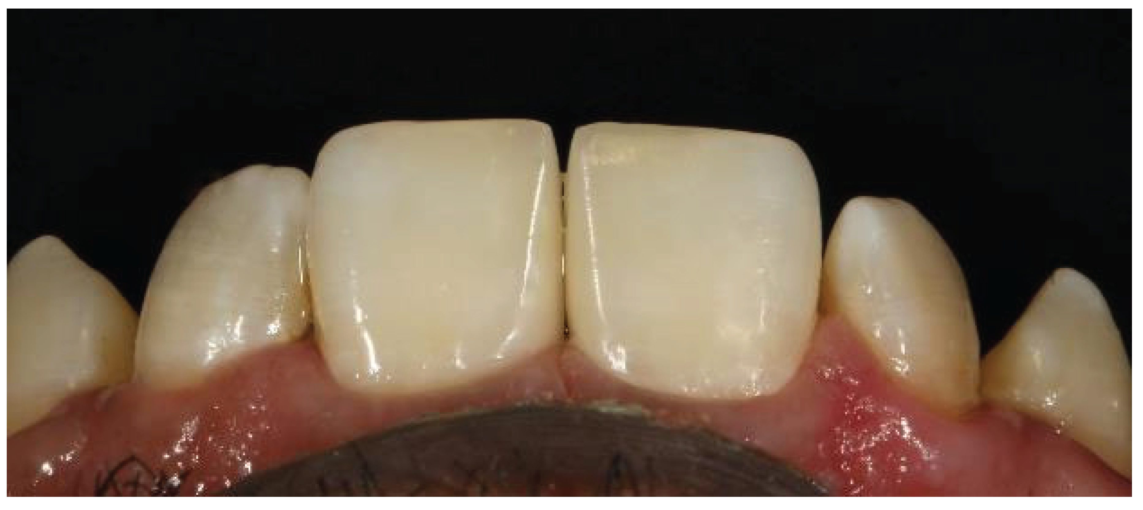
Figure 50.
Palatal view.
Disclaimer/Publisher’s Note: The statements, opinions and data contained in all publications are solely those of the individual author(s) and contributor(s) and not of MDPI and/or the editor(s). MDPI and/or the editor(s) disclaim responsibility for any injury to people or property resulting from any ideas, methods, instructions or products referred to in the content. |
© 2025 by the authors. Licensee MDPI, Basel, Switzerland. This article is an open access article distributed under the terms and conditions of the Creative Commons Attribution (CC BY) license (http://creativecommons.org/licenses/by/4.0/).
Copyright: This open access article is published under a Creative Commons CC BY 4.0 license, which permit the free download, distribution, and reuse, provided that the author and preprint are cited in any reuse.


