
Submitted:
08 July 2025
Posted:
09 July 2025
You are already at the latest version
Abstract
Extended-reach drilling (ERD) offers significant economic and operational advantages but poses severe friction challenges due to complex wellbore geometries and extreme operating conditions. This study investigates the multi-interface lubrication behavior of OBDFs, particularly under high-pressure and high-temperature environments encountered in ERD. A series of laboratory tests were conducted to evaluate the lubrication performance of OBDFs at metal-rock, metal-mud cake, and metal-metal interfaces using specialized apparatus. Lubricants including PF-LUBE OB, PF-LUBE EP, and CX-300 were assessed across varying concentrations, loads, and simulated formations. Results show that at 2 wt% dosage, PF-LUBE EP reduced the metal-rock friction coefficient from 0.01025 to 0.00648 (a 36.8% decrease), metal-mud cake interface from 0.23075 to 0.16726 (−27.5%), and metal-metal from 0.11943 to 0.08058 (−32.5%). A quantitative scoring system standardized against water and base oil was developed to compare overall lubrication efficiency, which PF-LUBE EP scored 155.39 on average (mineral oil = 100). The findings highlight that effective lubricant selection and dosage optimization are critical for ensuring safe and efficient ERD operations, especially in offshore environments. This work provides technical guidance for enhancing drilling fluid formulations to mitigate frictional issues and improve drilling reliability under extreme conditions.
Keywords:
ERD
; OBDFs
; friction reduction
; lubrication performance
; multi-interface
; extreme pressure
1. Introduction
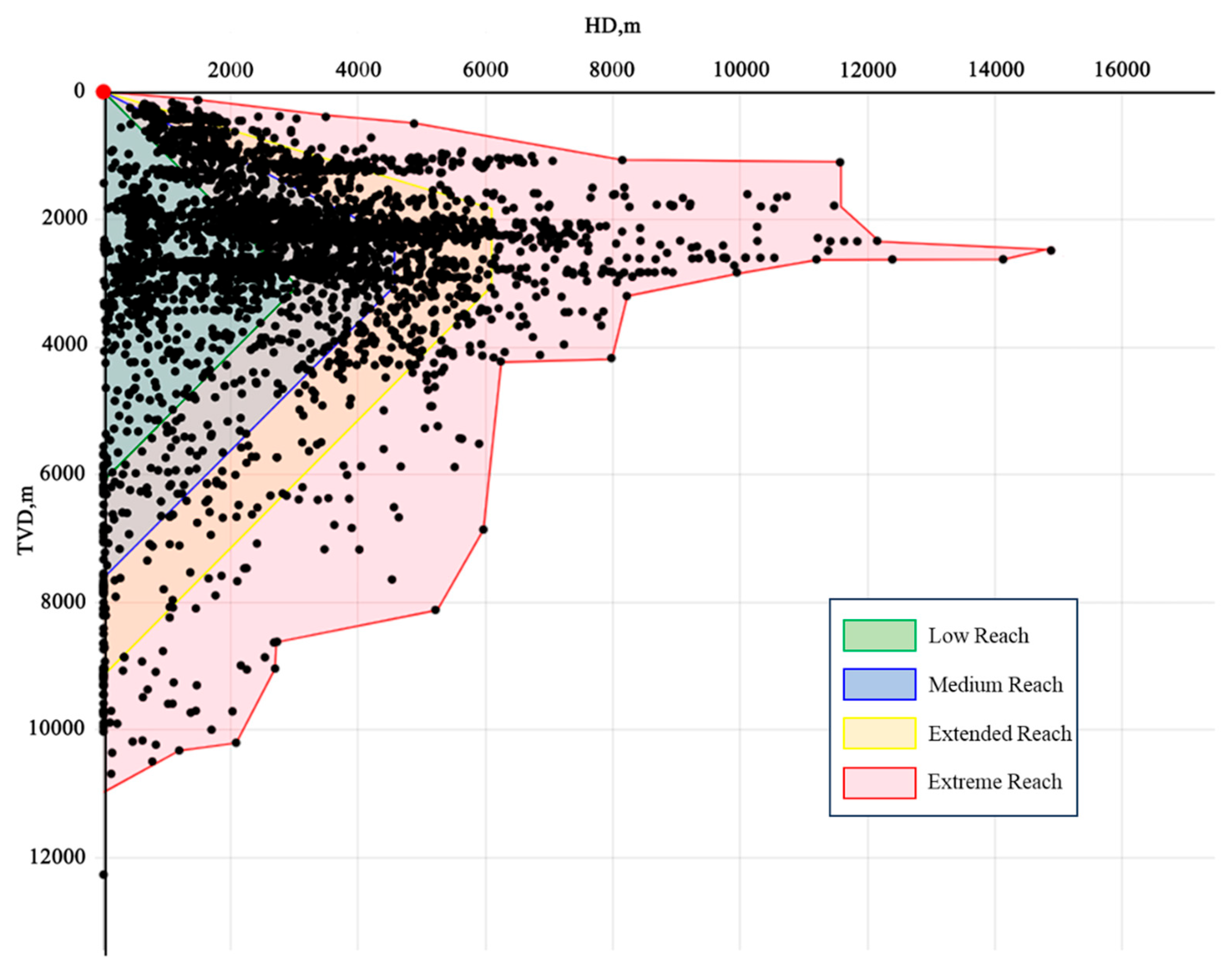
The ERD technology is currently widely used in oilfield development, particularly in offshore operations. Its primary advantage lies in the ability to cover a large area of reservoirs (especially thin layers or scattered oil reservoirs), while significantly reducing the number of drilling platforms and surface facilities required, cutting down development costs [1,2,3]. According to past experience, ERD can be classified into four types based on different horizontal-vertical ratio (HVR): low reach, medium reach, extended reach and extreme reach, with an HVR exceeding 3.33 and horizontal displacements is greater than 6,096 m (20,000 ft) [4,5]. Figure.1 shows the drilling displacements worldwide [6]. It can be seen from the figure that with the demands of oilfield development and the advancement of technology, an increasing number of wells are located in the extreme extended reach area. Nowadays, the maximum well depth of extended reach wells has currently exceeded 15,000m, reaching 15,240m (TVD of 2,469m and HD of 14,198m) [7].
Figure 1.
Worldwide drilling displacements and classifications.
Despite these advancements, deeper ERD wells present a range of technical challenges, with friction being a primary concern [8]. Unlike vertical wells, ERD configurations involve significantly greater horizontal displacements. From a lateral perspective, the drill string bends under gravitational forces and often rests against the lower side of the wellbore wall [9,10]. This contact substantially increases the contact area and normal pressure, thereby resulting in a significant rise in frictional torque [11]. Jia et al. [12] investigated the frictional and torque behavior of drill strings in ERD wells by developing a modified three-dimensional soft-string model. Their model demonstrated strong predictive capabilities for well A but showed limitations when applied to large-scale or extreme-depth operations. Similarly, Ihua-Maduenyi et al. [13] conducted torque and drag simulations to evaluate drill string integrity under various frictional regimes, focusing on operations in the Niger Delta. Their findings emphasized the value of predictive modeling in mitigating downhole challenges. Nonetheless, they acknowledged the need for more robust models tailored to extreme wellbore conditions encountered in deep ERD scenarios.
Oil-based fluids (OBDFs) are widely recognized for their superior lubricity, primarily attributed to the base oil component [14]. Compared with water-based drilling fluids, OBDFs exhibit significantly lower friction coefficients [15]. This advantage allows for the formation of a continuous and stable oil film between the drill string and the wellbore wall, which helps to minimize frictional resistance, reduce tool wear, and enhance drilling efficiency (Figure 2a). However, under extreme high-temperature and high-pressure (HTHP) conditions—typically above 150 °C and 30 MPa—the stability of the oil film deteriorates markedly [16]. The film becomes susceptible to rupture or desorption, leading to direct contact between the drill string and the wellbore or casing. This results in a sudden and sharp increase in friction (Figure 2b), which not only elevates energy consumption but also increases the risk of downhole accidents such as pipe sticking, potentially interrupting operations and causing severe economic losses [17].
In complex geological settings, particularly when drilling through low-permeability formations, filtration losses are minimal. As a result, the drilling fluid often fails to form an effective mud cake on the wellbore wall, leading to direct contact between the drill string and the exposed formation rock [18]. Conventional extreme-pressure lubrication tests typically assess steel–steel friction pairs, while mud cake adhesion tests examine steel–mud cake interfaces—neither of which fully replicate the range of actual downhole contact scenarios encountered in extended-reach drilling (ERD) operations [19,20]. Yu et al. [21] investigated the frictional behavior of rock surfaces under high-pressure conditions in tight gas reservoirs and highlighted the complexity of drill string–rock interactions. However, their work did not provide a comprehensive framework for steel–rock friction under ERD-specific conditions. Zhang et al. [22] examined wear-resistant materials used in drill joints for deep and ultra-deep wells, affirming the importance of lubrication in mitigating frictional wear. Yet, their research also fell short in addressing the nuanced friction dynamics specific to ERD environments, particularly where lubrication may be insufficient or absent due to formation properties.
To address these gaps, the present study systematically investigates the friction and lubrication characteristics of OBDFs across multiple interface types. Using a suite of specialized test protocols, we evaluate the performance of different lubricant formulations under varying contact surfaces, load conditions, and additive concentrations. Furthermore, a quantitative evaluation framework is developed, benchmarking against distilled water and base oil to normalize performance across all test scenarios. The objective is to identify and optimize an oil-based lubricant capable of maintaining operational integrity and reducing friction-related risks in ERD applications, particularly in offshore drilling environments.
2. Materials and Methods
2.1. Materials
W1-110 mineral oil was used in accordance with the NB/SH/T 0913-2015 standard for Light White Oil. Analytical-grade calcium chloride was employed. Additional materials for the preparation of OBDFs—including primary emulsifier PF-EMUL, auxiliary emulsifier PF-COAT, organoclay PF-HIVIS, alkalinity regulator PF-MOALK, plugging agent PF-MOLSF, filtrate reducer PF-MOHFR, gel-strength enhancer PF-HIRHEO-3, lubricants (PF-LUBE OB, PF-LUBE EP, CX-300), and weighting agents—were supplied by COSL Shanghai Branch.
2.2. Experiment Apparatus
The HZKM-2 extreme pressure and anti-wear tester (Baoding Huazheng Electric) was used to evaluate lubrication under high-load conditions. The NZ-3A mud cake adhesion coefficient tester (Qingdao Haitongda) and the 112-00-C-EP lubricity tester (OFI Testing Equipment) were employed for interface-specific measurements. Additional apparatus used for testing OBDFs complied with the API RP 13B-2-2023 standard Field Testing of Nonaqueous-Based Drilling Fluids.
2.3. Methods
Before evaluating the improvement effect of the lubrication performance at each interface, it is necessary to assess its impact on the properties of the oil-based drilling fluid, so as to avoid adverse effects on the drilling fluid properties after its addition.
2.3.1. Drilling Fluid Properties
The oil-based drilling fluid was formulated as follows: 340 mL of W1-110 mineral oil, 60 mL of 25 wt% CaCl2 aqueous solution, 19.2 g of primary emulsifier (PF-EMUL), 4.8 g of auxiliary emulsifier (PF-COAT), 12 g of organoclay (PF-HIVIS), 12 g of alkalinity regulator (PF-MOALK), 12 g of plugging agent (PF-MOLSF), 12 g of filtrate reducer (PF-MOHFR), and 3.2 g of gel-strength enhancer (PF-HIRHEO-3). Weighting materials were then added to adjust the fluid density to 1.5 g/cm3.
The rheological and performance characteristics of the prepared oil-based drilling fluid were tested before and after hot-rolling at 150 °C, following procedures outlined in API RP 13B-2-2023 Field Testing of Nonaqueous-Based Drilling Fluids.
2.3.2. Friction Test at the Metal-Rock Interface
A schematic diagram of the metal–rock interface friction test apparatus is shown in Figure 3. The core testing unit is the HZKM-2 extreme pressure and anti-wear tester, which operates using an electric motor-driven rotating mechanism. On the left side of the setup, a tachometer is employed to monitor rotational speed, while a volt-ammeter measures real-time voltage and current outputs. Upon completion of the test, the circuit is switched, and a multimeter is used to measure the total resistance of the system. All time-dependent measurement data are collected and transferred to a computer for further analysis.
The physical configuration of the HZKM-2 tester is illustrated in Figure 4a. Notably, the sliding component in contact with the sample is interchangeable. A steel slider is used initially to simulate steel–steel friction conditions. In this study, we replaced the steel slider with custom-fabricated artificial sandstone specimens (Figure 4b), prepared by cutting quartz-based sandstone blocks with varying particle sizes into 1 cm-long cuboids, to mimic formation rocks of different permeabilities.
The overall power of the instrument includes the kinetic energy change of the drive shaft, the internal frictional resistance of the instrument, the frictional resistance of the slider, and the current thermal effect. It can be expressed as:
where P is the total power, W; ΔPk is the kinetic energy change of the drive shaft, W; Pi is the internal frictional resistance of the instrument, W; Pf is the frictional resistance of the slider, W; PQ is the current thermal effect, W; I is the current, A; R is the resistance of instrument, Ω.
When the instrument rotates steadily, the kinetic energy of the drive shaft remains unchanged, and the power generated by the current is zero, that is:
In the no-load condition, P0 reflects the internal frictional resistance of the instrument.
Since the heat generated by friction is proportional to the angular velocity, the interfacial friction coefficient can be expressed as [23]:
where D is the diameter of the ring, cm; fr is the friction coefficient of metal-rock interface; F is the contact load, N; ω is the angular velocity of the rotating shaft, rad/s.
So, we obtained the friction coefficient of the metal-rock interface according to equation (1) – (4):
During the test, first turn on the switch and let the instrument rotate under no-load condition for 15 minutes, then read the stable current I0 at this time. After turning off the switch, use a multimeter to measure the resistance R0 of the entire instrument. Put the simulated core in, and pour oi-based drilling fluid into the sample cup. After assembling the 1# and 2# levers, add a 1 kg load. Turn on the switch again, run it for 5 minutes, and read the stable current I1 and stable rotational speed ω at this time. After turning off the switch, use a multimeter to measure the resistance R1 of the entire instrument again.
2.3.3. Friction Test at the Metal-Mud Cake Interface
The friction behavior at the metal–mud cake interface was assessed using the NZ-3A mud cake adhesion coefficient tester (Figure 5). Prior to testing, mud cakes were prepared via an API fluid loss test on OBDFs subjected to hot rolling. The mud cake formed after a 30-minute test was collected for evaluation.
To initiate the test, the sliding plate was rotated to a horizontal position, and the three leveling wheels located beneath the outer shell were adjusted to center the bubble in the spirit level. The zero-reset button was then pressed to calibrate the angle on the LCD display to zero. The prepared mud cake was gently placed onto the surface of the sliding plate, followed by the careful positioning of a metallic sliding block on top. The setup was allowed to rest undisturbed for one minute to stabilize the interface contact. Subsequently, the start/stop button was pressed to activate the micromotor, which gradually tilted the sliding plate via a transmission mechanism. When the sliding block began to move, the start/stop button was pressed again to halt the device. The critical tilt angle at which motion occurred was recorded from the LCD screen.
The friction coefficient between the metal and mud cake interface (fc) was calculated as the tangent of the measured angle θ, using the following equation:
where fc is the t friction coefficient of metal-mud cake interface; θ is the angle at which the sliding block starts to slide.
2.3.4. Friction Test at the Metal-Metal Interface
The frictional performance between metallic surfaces was evaluated using a standardized lubricity tester, as shown in Figure 6. To conduct the lubricity test, first clean the lubricity test ring and the test block with acetone, followed by thorough rinsing with deionized water, ensuring all machine parts in the sample area are spotless and avoiding bare-hand contact with metal surfaces. Install the test ring on the tapered main shaft, and preheat the machine for 15 minutes. Set the motor speed to 60 RPM, place the test block in the holder with the concave side outward, and zero the torque reading after 15 minutes of operation.
After the instrument is preheated, fill the stainless-steel cup with 260-280 mL of the test fluid, submerge the ring, block, and holder, and zero the torque again. Position the torque arm, apply 150 inch-pounds of torque, start the timer, record the torque reading after 5 minutes, and release the torque. Use water as a reference with a friction coefficient of 34±2 at 60 RPM and 150 inch-pounds; if outside this range, do not proceed. Calculate the friction coefficient of metal-metal interface as follows:
where fm is the friction coefficient of metal-metal interface; Nm is the torque reading for mud (oil-based drilling fluid) and Nw is the torque reading for distilled water.
3. Results
3.1. Base Properties
3.1.1. Rheological Properties
A six-speed rotational viscometer was employed to determine the rheological properties of OBDFs containing 2 wt % lubricant. The results are summarized in Table 1. Hot-rolling was carried out at 150 °C for 16 h to simulate the high-temperature conditions encountered during down-hole circulation. As shown in Table 1, the viscosity of the base fluid decreased after hot-rolling. This reduction is attributable to the thermally induced desorption of surfactants from the organoclay, which converts surface-bound, water-wetted bentonite into oil-wetted organoclay; the diminished lipophilicity weakens its viscosity-enhancing capability.
The addition of lubricants had little influence on the fluid’s rheology, indicating that cuttings-transport performance remains adequate for normal drilling operations. A slight post-rolling viscosity decline was observed for the CX-300-treated system, probably because ester-based lubricants undergo hydrolysis at elevated temperatures, producing fatty acids that react with the alkalinity regulator, thereby lowering system alkalinity and hindering organoclay dispersion.
3.1.2. Plugging Properties
- Filtrate loss
The filtrate loss is a critical parameter in evaluating the performance of drilling fluids. When filtrate from the drilling fluid invades the formation, it can gradually transmit hydrostatic pressure from the wellbore to the surrounding strata. This pressure transmission elevates near-wellbore stress and may contribute to wellbore instability. The effects of different lubricants on the filtration behavior of OBDFs are summarized in Table 2. Results indicate that the addition of lubricants had minimal impact on both standard API and HTHP filtrate loss.
- 2.
- Sand bed test
The sand bed test offers direct insight into the depth of filtrate invasion, using quartz sand to simulate reservoir rock. The invasion depths of OBDFs formulated with different lubricants are presented in Table 3. Among the tested systems, the fluid containing CX-300 exhibited a notably deeper invasion depth compared to the others. This effect is likely due to the adsorption of the lubricant onto the quartz surface, which alters the surface wettability and capillary pressure, thereby facilitating filtrate penetration into the formation. Such behavior may pose potential operational risks during drilling.
3.2. Lubricating Properties
3.2.1. Friction Coefficient of Metal-Rock Interface
- 1.
- Influence of Dosage
The amount of lubricant added is a key factor influencing the friction coefficient. Through friction performance tests at the metal-rock interface, we found that at the initial stage of lubricant addition, the friction coefficient decreased significantly. This effect is attributed to the lubricant’s ability to fill microscopic surface irregularities between the metal and rock, thereby smoothing the contact interface and reducing friction.
For PF-LUBE EP, increasing the concentration from 0% to 2 wt% resulted in a substantial reduction in the metal–rock friction coefficient from 0.010246 to 0.006478, reflecting a reduction ratio of 36.8%. This pronounced decline suggests that 2 wt% represents the saturation point for surface adsorption and lubricating film formation. A further increase to 3 wt% led to only marginal improvement, with the friction coefficient decreasing to 0.006255—an additional reduction of just 2.3% compared to the 2 wt% case.
For CX-300, the minimum friction coefficient was observed at 1.5 wt%, indicating that surface adsorption reaches saturation at this dosage. Additional increases in lubricant concentration did not significantly enhance performance, suggesting diminishing returns beyond the saturation threshold.
From a cost-effectiveness perspective, it is essential to optimize lubricant dosage based on specific operational conditions to minimize additive costs without compromising performance. Based on these findings, a 2 wt% lubricant concentration was selected as the benchmark for all subsequent experimental evaluations.
- 2.
- Influence of load
The influence of applied load on the friction coefficient is also non-negligible. Under extreme pressure conditions, rupture of the lubricating oil film is the primary cause of the rapid increase in friction. In the test setup, the unit load applied to the contact surface was amplified 28-fold through the combined action of the primary (lever #1) and secondary (lever #2) force arms.
During the experiment, the system was first operated under a constant load for 5 minutes to ensure stable performance. The load was then incrementally increased, and testing continued for an additional 5 minutes. Friction coefficients under different loading conditions were calculated and are presented in Figure 8.
At the standard load of 1 kg—equivalent to 28 kg or approximately 274.4 N at the contact surface—the friction coefficient of the base fluid was measured at 0.10246. With the addition of 2 wt% PF-LUBE OB, the coefficient was significantly reduced to 0.00689. However, when the applied load was increased to 12 kg, the coefficient rose to 0.1134, reflecting a 10.6% increase relative to the initial condition. This increase is attributed to partial breakdown of the lubricating film under higher stress.
As shown in Figure 8 , when the lubricant concentration is held constant, the friction coefficient generally increases with rising applied load. This trend is attributed to the increased number of asperities contact points between the metal and rock surfaces under higher load, which leads to elevated contact pressure and enhanced adhesive friction.
Although the addition of lubricant moderates the rate of increase in the friction coefficient, the distribution and stability of the lubricant film become critical determinants of frictional behavior under high-load conditions. Thus, maintaining the structural integrity and effectiveness of the lubricating film is essential for achieving optimal lubrication performance in extreme loading environments.
- 3.
- Influence of formation
In the laboratory, artificial sandstones with varying particle sizes were used to simulate the effects of different geological formations on the friction coefficient. The particle sizes ranged from 180 μm to 9.6 μm, representing a spectrum from coarse sandstone to siltstone formations. The corresponding friction coefficients are presented in Figure 9. Experimental results demonstrate that rock type significantly influences lubricant performance. When simulating drilling through formations with particle sizes decreasing from 180 μm (coarse sandstone) to 9.6 μm (siltstone), the friction coefficient associated with PF-LUBE EP decreased from 0.006478 to 0.005092—a 21.4% reduction. This decline is attributed to the smoother contact interfaces and lower permeability of fine-grained formations, which facilitate the formation of a stable, continuous oil film and thus reduce friction more effectively.
In contrast, high-permeability sandstones or crushed rocks present rougher and more irregular contact surfaces. These conditions hinder the uniform distribution of the lubricant and compromise the integrity of the lubricating film, resulting in elevated friction coefficients.
However, under actual drilling conditions, the friction interface varies depending on the formation permeability. In high-permeability formations, filtrate from the drilling fluid readily invades the formation, leading to the formation of a mud cake along the wellbore wall. As a result, the friction coefficient between the drill string and the mud cake becomes the primary parameter of interest.
As low-permeability formations typically do not allow sufficient filtrate invasion to form an effective mud cake. Under such conditions, dry contact occurs between the drill string and the bare formation rock, often under high axial loads. This scenario poses a greater frictional challenge and is therefore the key concern when drilling through tight formations.
It is important to note, however, that the reduced friction coefficients observed in laboratory simulations of low-permeability formations do not necessarily indicate improved operational lubricity in the field. In real drilling conditions, such formations often do not allow the development of a continuous mud cake due to limited filtrate invasion. As a result, the drill string may come into direct contact with bare formation rock under high axial stress, leading to increased abrasive wear and frictional resistance. Therefore, the frictional advantages seen in fine-grained artificial rock specimens should be interpreted within the limitations of static laboratory conditions.
3.2.2. Friction Coefficient of Metal-Mud Cake Interface
When the drill string contacts the mud cake, interfacial lubrication directly influences torque and drag during drilling operations. Inadequate lubrication at this interface can lead to increased friction, resulting in drill string sticking or jamming. To evaluate this behavior, a friction test was conducted between a metal block (simulating the drill string) and an API-standard mud cake (simulating the filter cake formed along the wellbore wall), thereby replicating the metal–mud cake interface encountered in real drilling scenarios.
This test enables the assessment of mud cake lubricity and anti-sticking performance, offering guidance for drilling fluid formulation adjustments to mitigate the risk of stuck pipe incidents. The experimental results for various lubricants are presented in Figure 10. Quantitatively, the base mud exhibited a friction coefficient of 0.23075. With the addition of 2 wt% PF-LUBE EP, the coefficient was reduced to 0.16726, representing a 27.5% decrease. Under the same dosage, PF-LUBE OB and CX-300 achieved coefficients of 0.18524 and 0.19428, corresponding to reductions of 19.3% and 15.8%, respectively, compared to the base mud.
The superior lubricating performance of PF-LUBE EP may be attributed to its ability to chemically interact with both the metallic surface and the mud cake, forming a semi-permanent boundary film. This film potentially prevents direct metal-to-cake contact and reduces adhesive friction. Furthermore, the enhanced hydrophobicity of the PF-LUBE EP–treated mud cake likely reduces mechanical interlocking between the drill string and filter particles, thereby contributing to lower drag forces.
3.2.3. Friction Coefficient of Metal-Metal Interface
Due to the substantial axial load applied during drilling, the drill string is subject to deformation and bending, which causes it to come into contact with the upper casing. This phenomenon is particularly pronounced in extended-reach drilling (ERD) operations. Such contact can result in wear on either the drill string or the casing, posing a significant risk of downhole failure or equipment damage. The friction coefficients at the metal–metal interface, as measured under different lubricant conditions, are presented in Figure 11.
As illustrated in Figure 11, all three lubricants contributed to a reduction in the metal–metal friction coefficient, with PF-LUBE EP exhibiting the most pronounced effect. The base mud displayed a friction coefficient of 0.11943, whereas the addition of 2 wt% PF-LUBE EP reduced this value to 0.08058—a 32.5% decrease.
PF-LUBE OB and CX-300 also demonstrated notable improvements, reducing the friction coefficient by 24.2% and 17.2%, respectively, compared to the base mud.
3.3. Quantitative Evaluation of Lubricants
Due to the differences in test apparatus, interfacial mechanics, and evaluation methodologies across the metal–rock, metal–mud cake, and metal–metal interfaces, direct comparison of absolute friction coefficients lacks inherent consistency. To enable a unified and objective assessment of lubricant performance, a normalized scoring system was established. In this framework, distilled water was designated as the baseline (score = 0), and W1-110 mineral oil served as the optimal reference (score = 100). The friction coefficients obtained under each interfacial condition were normalized via linear transformation and subsequently integrated using a weighted average to yield a comprehensive performance score (Figure 12).
Among the tested candidates, PF-LUBE EP achieved the highest overall score of 466.17(155.39 on average), indicating superior and well-balanced performance across all three interfaces. At the metal–rock interface, PF-LUBE EP reduced the friction coefficient to 0.00648, compared to 0.02294 for water and 0.01146 for W1-110 mineral oil, yielding a normalized score of 143.45—outperforming PF-LUBE OB and CX-300 by 2.6% and 8.7%, respectively. At the metal–mud cake interface, the coefficient decreased to 0.16726, corresponding to a score of 186.19, again surpassing PF-LUBE OB (174.99) and CX-300 (169.35). For the metal–metal interface, PF-LUBE EP achieved a coefficient of 0.08058 and a normalized score of 136.54, marking a 17.6% improvement relative to base mud.
A key finding of this analysis is the consistency and robustness of PF-LUBE EP under varying conditions, including dosage levels, applied loads, and simulated formation lithologies. This superior performance is attributed to its molecular architecture: the organophosphorus groups form strong coordination bonds with Fe atoms on the metal surface, generating a stable “anchoring layer,” while the outward-oriented alkyl chains establish a mobile “slip layer.” This dual-layer structure, inspired by the bionic architecture of sea anemones, enables the formation of a self-repairing lubricating film that resists microcrack propagation and pressure-induced breakdown.
The proposed multi-interface scoring framework offers a systematic and quantitative approach for screening and optimizing lubricants in ERD applications. It facilitates rational formulation design under complex wellbore geometries and heterogeneous lithologies, ultimately improving drilling safety, efficiency, and cost-effectiveness.
4. Discussion
The multi-interface frictional evaluation framework developed in this study offers a comprehensive perspective for assessing lubricant performance under conditions representative of actual ERD operations. Results indicate that PF-LUBE EP exhibits superior lubricating performance across metal-rock, metal–mud cake, and metal–metal contact surfaces, particularly under HTHP environments. The superior performance of PF-LUBE EP under high-pressure metal-rock conditions is attributed to its organophosphorus group, which forms strong coordination bonds with Fe atoms on metal surfaces. This interaction creates a robust chemically adsorbed “anchoring layer.” Above this, the flexible alkyl chains extend into the oil medium, forming a dynamic and mobile “slip layer” that minimizes contact friction by promoting shear accommodation at the lubricant-oil interface. This dual-layer model, reminiscent of a bionic sea-anemone structure, ensures a self-healing lubricating film that remains effective even under microfracture-induced perturbations (Figure 13). These findings imply that lubricant selection should consider not only friction coefficients but also the chemical adaptability of the additive to the expected interface type and thermal regime. This can be a determining factor in minimizing torque-and-drag-induced downtime during ERD.
Under metal–rock conditions, PF-LUBE EP’s unique ability to maintain structural integrity of the lubricating film under escalating load conditions underscores its robustness. This is particularly critical in tight formations where low-permeability rocks prevent mud cake formation, leading to direct rock-metal contacts with high axial loads. Unlike CX-300 or PF-LUBE OB, PF-LUBE EP consistently outperforms in terms of both absolute and normalized friction coefficient values, offering tangible risk reductions in pipe sticking, torque spikes, and tool failure.
The study also demonstrates that friction coefficients are significantly influenced by geological factors, such as lithology and formation permeability. Experiments with synthetic sandstones of varied grain sizes simulate realistic drilling scenarios and highlight how smaller particle sizes—mimicking siltstone—facilitate improved lubricant dispersion and film formation. This further emphasizes the necessity of tailoring lubricants not just to drilling fluids, but to anticipated lithological profiles. While laboratory tests using fine-grained artificial rocks (e.g., 9.6 μm siltstone) showed a notably reduced metal–rock friction coefficient—ostensibly suggesting superior lubricity under such conditions—this may not fully reflect the actual downhole scenario. In practice, tight formations typically exhibit minimal filtrate loss, which prevents the formation of a protective mud cake. Consequently, the drill string is more likely to encounter direct contact with the bare formation under high axial loads. This contact is often more abrasive and frictionally severe than what is captured in static laboratory tests. Therefore, the apparent improvement in friction performance in low-permeability formations should be interpreted with caution, as it may underestimate the real frictional challenges encountered during extended-reach drilling in tight rock environments.
At the metal–mud cake interface, PF-LUBE EP reduces adhesive interactions by altering the mud cake’s surface energy and increasing hydrophobicity. The resulting semi-permanent boundary film imparts resistance to mechanical interlocking and enhances the anti-sticking properties of the drilling fluid. Notably, such improvements in lubricity were achieved without compromising other key drilling fluid properties, including rheology, filtration, and invasion depth.
The implementation of a quantitative scoring framework based on normalized values offers a reproducible method for benchmarking lubricants under variable operational parameters. This multidimensional approach bridges the gap between laboratory-scale friction testing and downhole performance forecasting. By capturing lubricant behavior under different contact mechanics and environmental stresses, it provides a practical guideline for lubricant formulation, selection, and dosage optimization in offshore and complex ERD drilling programs.
Ultimately, this study not only validates PF-LUBE EP as a leading candidate for challenging ERD environments but also establishes a holistic framework for future development and evaluation of next-generation oil-based drilling lubricants.
While the present study comprehensively evaluates the tribological performance of OBDF lubricants across three typical contact interfaces—metal–rock, metal–mud cake, and metal–metal—several critical gaps remain between the laboratory protocols and actual downhole conditions. These discrepancies highlight both the limitations of current test methodologies and opportunities for future refinement.
One notable observation is that the metal–mud cake interface exhibited the highest friction coefficient among the three interfaces, with a base fluid value of 0.23075 and a 27.5% reduction achieved by PF-LUBE EP at 2 wt%. Although these values are valid within the context of standardized laboratory tests, they may overestimate the actual frictional resistance encountered in the borehole. In real drilling scenarios, oil-based fluids tend to penetrate and saturate the mud cake, altering its surface energy, porosity, and mechanical interaction with the drill string. This dynamic behavior results in reduced interfacial adhesion and enhanced lubrication, a process not adequately simulated in static adhesion tests such as those performed with the NZ-3A apparatus. Consequently, future test designs should incorporate fluid flow simulation, mud cake permeability evolution, and cyclic shear conditions to better represent the real-time lubrication environment experienced during ERD.
A second area of concern lies in the metal–rock interface testing, particularly when simulating contact with low-permeability, fine-grained formations. The experimental results showed that rock types with smaller particle sizes (e.g., 9.6 μm artificial siltstone) yielded the lowest friction coefficient (0.005092), suggesting improved lubricant film formation on smoother surfaces. However, this apparent advantage in laboratory conditions may be misleading in practice. Tight formations typically exhibit negligible filtration loss, making the formation of an effective mud cake virtually impossible. As a result, the drill string may directly contact the bare rock surface under high axial loads, creating a highly frictional and abrasive interface despite favorable surface roughness metrics. Therefore, the frictional behavior under composite conditions—where formation lithology, permeability, and mud cake formation dynamics interact—warrants further investigation. Future research should focus on multi-layered interface modeling, considering the sequential or partial development of filter cake over various rock types, and how this affects the spatial distribution and effectiveness of lubricant films.
In summary, while the study presents a robust framework for lubricant screening via normalized scoring, bridging the gap between lab-scale characterization and field-scale application demands further refinement of interface-specific models and dynamic test conditions. Such efforts are critical for ensuring optimal drilling fluid performance in increasingly complex ERD environments.
5. Conclusions
Through a systematic evaluation of three oil - based drilling fluid lubricants, we have obtained the following conclusions:
1. In this study, PF-LUBE EP exhibited the best overall lubricating performance among the three tested oil-based drilling fluid additives, significantly reducing friction coefficients at metal–rock, metal–mud cake, and metal–metal interfaces. Its bionic dual-layer structure—comprising an organophosphorus anchoring layer and a mobile alkyl slip layer—demonstrated excellent stability and adaptability under extreme high-pressure and high-temperature conditions encountered in ERD operations.
2. The friction-reducing effect of lubricants was found to be strongly dependent on interface characteristics and formation lithology. In particular, tight formations with low permeability, where mud cakes are difficult to form, pose the highest frictional risk. PF-LUBE EP maintained superior performance across varying simulated rock textures, confirming its suitability for a broad range of downhole contact conditions.
3. Lubricant dosage plays a critical role in performance optimization. For PF-LUBE EP, 2 wt% was identified as the optimal concentration, beyond which further increases yielded only marginal improvements. This finding supports a cost-effective dosage strategy that balances additive cost with friction mitigation efficiency in practical drilling scenarios.
4. A multi-interface quantitative scoring system was established to normalize and compare lubricant performance across different friction environments. This framework allows for consistent, objective evaluation and can serve as a practical tool for lubricant screening and formulation in complex ERD applications, ultimately enhancing drilling safety, efficiency, and economic viability.
Author Contributions
Conceptualization, W.L. and L.W.; methodology, F.S.; validation, X.T. and J.W.; formal analysis, X.T.; investigation, J.W.; resources, B.C.; data curation, X.T.; writing—original draft preparation, X.T.; writing—review and editing, J.W.; visualization, X.T.; supervision, F.S.; project administration, W.L.; funding acquisition, M.Z. All authors have read and agreed to the published version of the manuscript.
Funding
This research was funded by Research on Drilling Fluid Technology Optimization for Ten-thousand-meter Extended-reach Wells in the East China Sea, grant number CCL2024SHPS006ET.
Data Availability Statement
The datasets used and analyzed during the current study available from the corresponding author on reasonable request.
Acknowledgments
The authors thank the anonymous reviewers for their valuable comments and suggestions.
Conflicts of Interest
The authors declare no conflicts of interest.
Abbreviations
The following abbreviations are used in this manuscript:
| ERD | Extended-reach drilling |
| HVR | Horizontal-vertical ratio |
| TVD | True vertical depth |
| HD | Horizontal displacement |
| OBDF | Oil-based drilling fluid |
| COSL | China Oilfield Services Limited |
| EP | Extreme pressure |
| API | American Petroleum Institute |
| RP | Recommended practice |
| RPM | Round per minute |
| AV | Apparent viscosity |
| PV | Plastic viscosity |
| YP | Yield point |
| FL | Filtrate loss |
| ES | Electrical Stability |
| BHR | Before hot rolling |
| AHR | After hot rolling |
References
- Zhang, L.; Xie, T.; Hou, X.; Li, W.; Jin, J. Study on Safe Drilling Cycle of Soft Mudstone of Minghuazhen Formation in An Oilfield in Bohai Sea. Unconventional Oil & Gas 2024, 11, 134–139. [Google Scholar] [CrossRef]
- Szymczak, P. D. Extended-Reach Drilling Hits Mainstream to Squeeze Difficult Reservoirs. Journal of Petroleum Technology 2021, 73, 35–40. [Google Scholar] [CrossRef]
- Wu, R.; Liu, Y.; Yu, H.; Lan, X.; Ai, X.; Guo, X.; Gao, P.; Deng, Fu. “Three-Low” Drilling Fluid Technology for Ultra-Shallow Horizontal Well with Extended Reach. Unconventional Oil &. Gas 2024, 11, 119–127. [Google Scholar] [CrossRef]
- Zhao, L.; Yi, T. Analysis of Coalbed Methane Horizontal Well Types and Drilling Technology Optimization. Coal Science and Technology 2020, 48, 45–53. [Google Scholar] [CrossRef]
- Li, Y.; Tian, J.; Guo, S.; Cai, B.; Ge, J. Research on Wellbore Cleaning Technology for Extended-Reach Wells in the East China Sea. Journal of Natural Science 2023, 12, 187–195. [Google Scholar] [CrossRef]
- Dog Nose Plot – K&M Technology Group. Available online: https://kmtechnology.com/dog-nose-plot/ (accessed on 8 June 2025).
- Adnoc Drilling Claims Longest Well Record. Available online: https://www.energyvoice.com/oilandgas/middle-east/exploration-production-middle-east/453178/adnoc-drilling-record-zakum/ (accessed on 10 June 2025).
- Huang, W.; Gao, D. Analysis of Drilling Difficulty of Extended-Reach Wells Based on Drilling Limit Theory. Petroleum Science 2022, 19, 211–222. [Google Scholar] [CrossRef]
- Mohammed, A.; Musab, A.; Bassam, A.; Kamran, A. An Innovative Approach Towards Real-Time Torque and Drag Model and Its Analysis-A Case Study. SPE Kingdom of Saudi Arabia Annual Technical Symposium and Exhibition, Dammam, Saudi Arabia. April 2017. [Google Scholar] [CrossRef]
- Rostagno, I. Friction Reduction Optimization for Extended Reach and Horizontal Wells. Doctor Thesis, The University of Texas at Austin, Texas, America, 5/2019. [Google Scholar] [CrossRef]
- Livescu, S.; Craig, S. A Critical Review of the Coiled Tubing Friction-Reducing Technologies in Extended-Reach Wells. Journal of Petroleum Science and Engineering 2017, 155, 252–260. [Google Scholar] [CrossRef]
- Jia, J; Yan, Z. ; Dou, Y.; Huang, G.; Ma, Q. The New Method and Application of Friction Torque for Extended Reach Well. Advances in Petroleum Exploration and Development 2014, 8, 37–42. [Google Scholar] [CrossRef]
- Ihua-Maduenyi, I. E.; Oguta, E. Mechanistic Evaluation of Drillstring Integrity in Extended Reach Wells Using Stiff String Torque and Drag Simulations under Variable Frictional Regimes. International Journal of Academic and Applied Research 2025, 9, 83–98. [Google Scholar]
- Oghenejoboh, K. M.; Ohimor, E. O. Application of Re-Refined Used Lubricating Oil as Base Oil for the Formulation of Oil-Based Drilling Mud-A Comparative Study. Journal of Petroleum Science and Engineering 2013, 4, 78–84. [Google Scholar] [CrossRef]
- Geng, Y.; Zhang, Z.; Yan, Z.; Yuan, Y.; Zhou, X.; Yue, W. A Novel Graphene/Triolein Complex-Based Lubricant for Improving High-Temperature Water Based Drilling Fluid. RSC Advances 2023, 49, 34772–34781. [Google Scholar] [CrossRef] [PubMed]
- Khan, M.A.; Al-Salim, H.S.; Leila, N. Development of High Temperature High Pressure (HTHP) Water Based Drilling Mud Using Synthetic Polymers, and Nanoparticles. Advanced Research in Fluid Mechanics and Thermal Sciences 2018, 45, 99–108. [Google Scholar] [CrossRef]
- D’Amicis, S.; Pagani, M.; Matteucci, M.; Piroddi, L. Stuck Pipe Prediction from Rare Events in Oil Drilling Operations. Upstream Oil and Gas 2023, 29, 125–140. [Google Scholar] [CrossRef]
- Dong, W.; Pu, X.; Ma, B. An Investigation on the Function of Mud Cakes on the Inhibition of Low Molecular Inhibitor for Water-Based Drilling Fluids. Energies 2019, 12, 3726. [Google Scholar] [CrossRef]
- Magzoub, M.I.; Ibrahim, M.H.; Nasser, M.S.; El-Naas, M.H.; Amani, M. Utilization of Steel-Making Dust in Drilling Fluids Formulations. Processes 2020, 8, 538. [Google Scholar] [CrossRef]
- Ezeakacha, C.P.; Salehi, S. Experimental Study of Drilling Fluid’s Filtration and Mud Cake Evolution in Sandstone Formations. Journal of Energy Resources Technology 2017, 139, 022912. [Google Scholar] [CrossRef]
- Zhang, K.; Wang, Z. Q.; Wang, D. G. Friction and Wear Behavior of Wear-Resistant Belts in Drill Joints for Deep and Ultra-Deep Wells. Strength of Materials 2015, 47, 771–781. [Google Scholar] [CrossRef]
- Yu, H.; Chen, Y.; Shu, Q.; Fang, F. Experimental Study of Friction Coefficient of Rocks in High Pressure and Tight Gas Reservoirs in Sichuan. Proceedings of the Institution of Mechanical Engineers 2018, 232, 678–687. [Google Scholar] [CrossRef]
- Zhang, C.; Guo, D.; Tian, J.; Niu, Q. Research on the Influencing Factors of Thermal Characteristics of High-Speed Grease Lubricated Angular Contact Ball Bearing. Advances in Mechanical Engineering 2021, 13, 16878140211027398. [Google Scholar] [CrossRef]
Figure 2.
Schematic diagrams of the lubrication mechanisms of oil-based drilling fluid under ideal conditions (a) and extreme pressure conditions (b).
Figure 2.
Schematic diagrams of the lubrication mechanisms of oil-based drilling fluid under ideal conditions (a) and extreme pressure conditions (b).
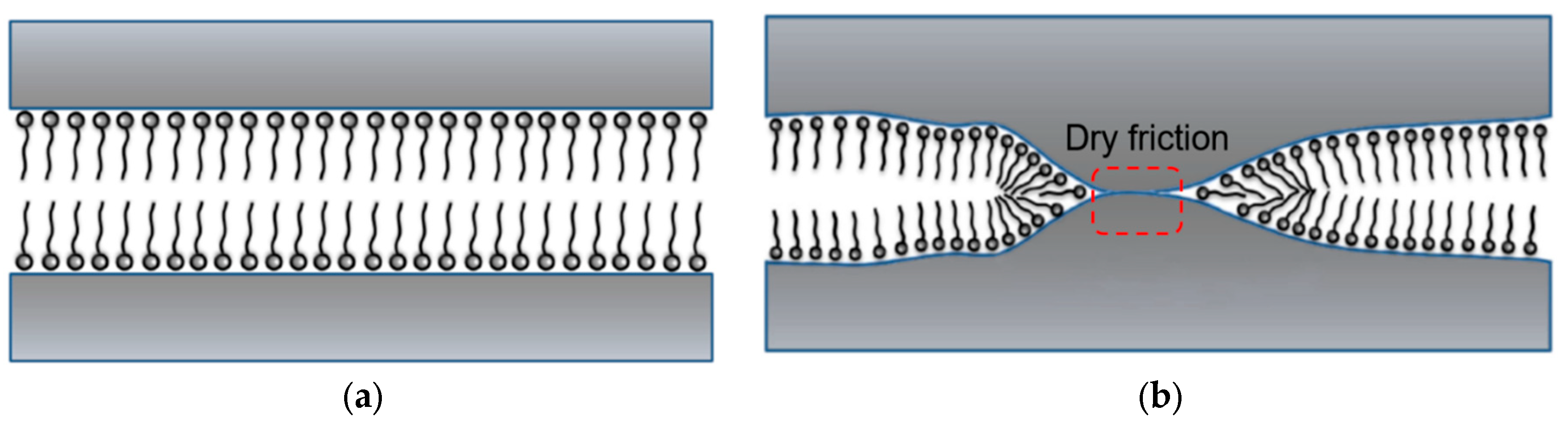
Figure 3.
Instrument schematic diagram of metal-rock interface friction test.
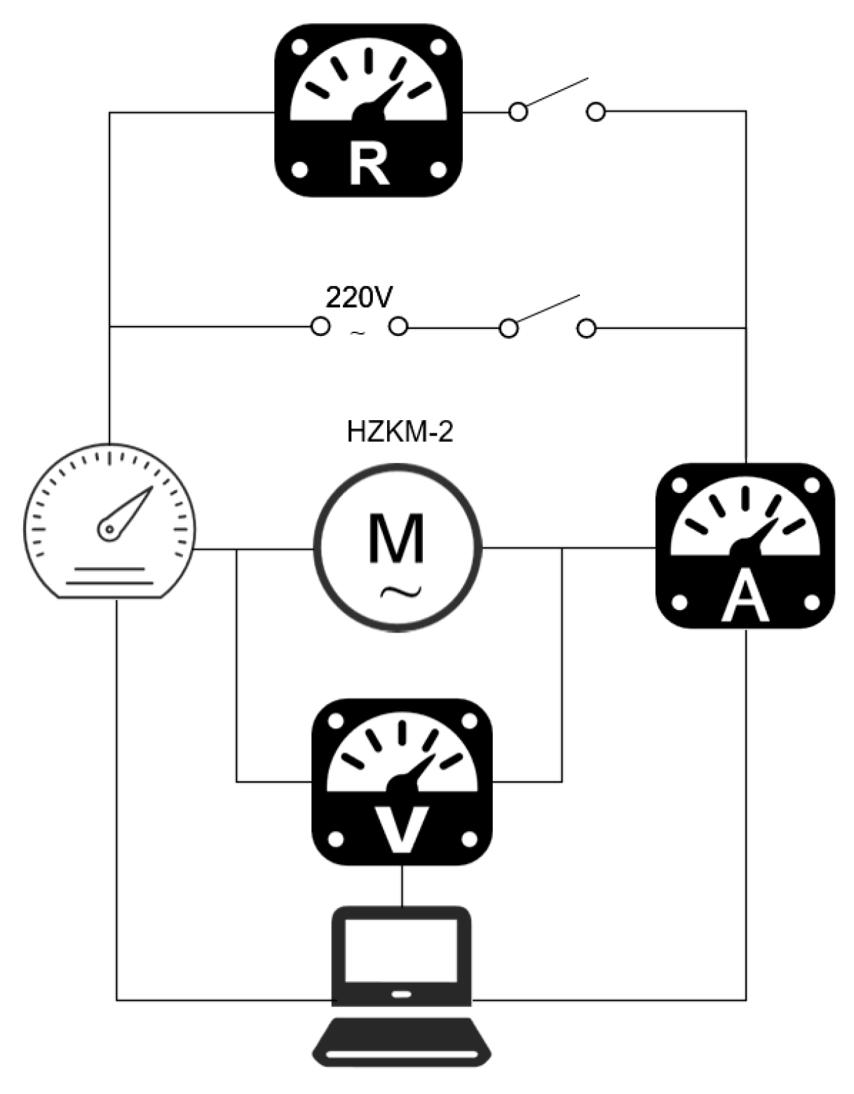
Figure 4.
HZKM-2 extreme pressure and anti-wear tester(a) and artificial sandstones(b).
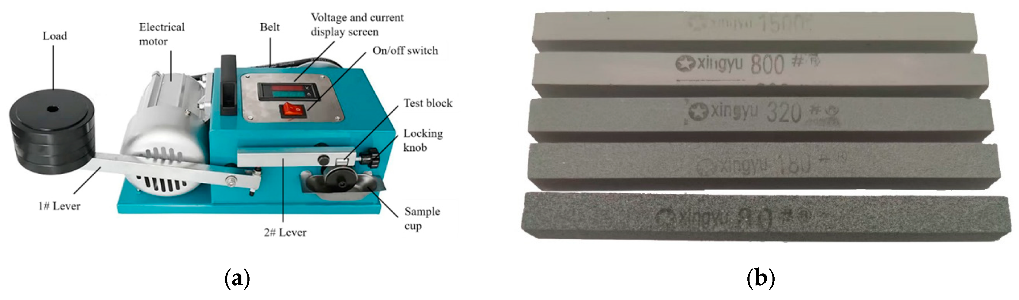
Figure 5.
NZ-3A mud cake adhesion coefficient tester.
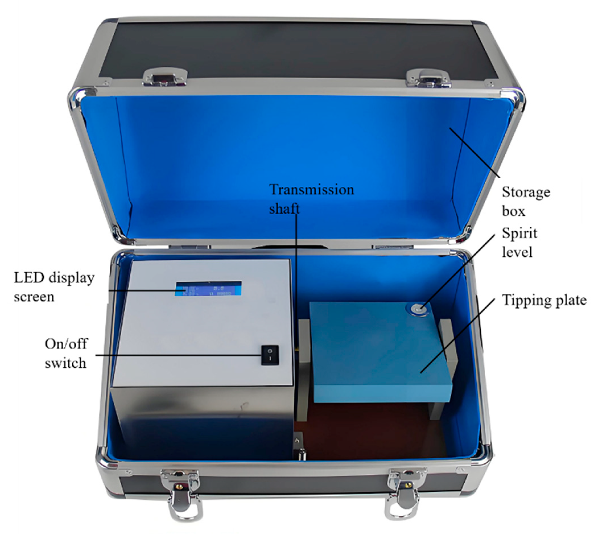
Figure 6.
112-00-C EP and lubricity tester
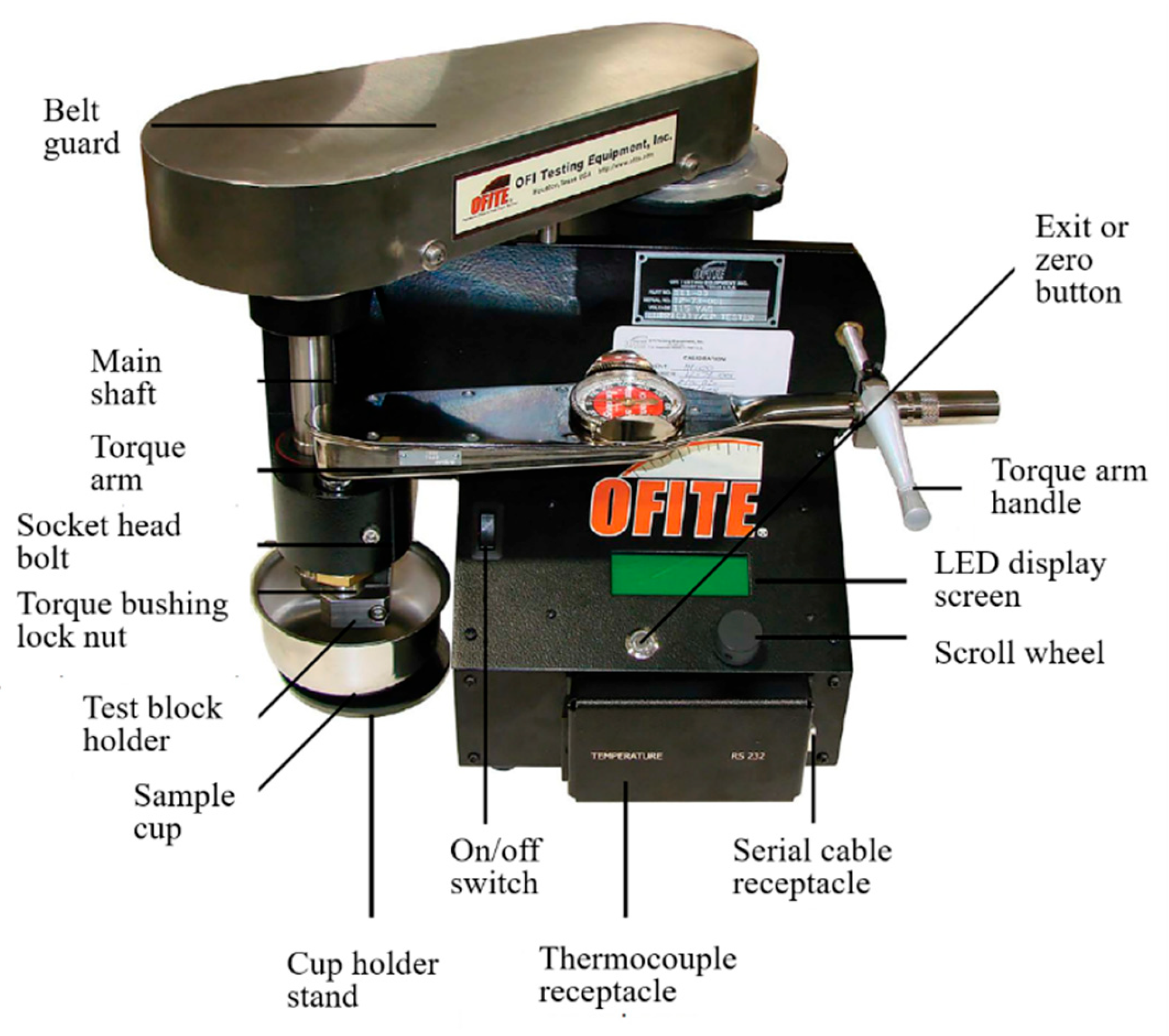
Figure 7.
Changes in the metal-rock friction coefficient under different addition dosage.
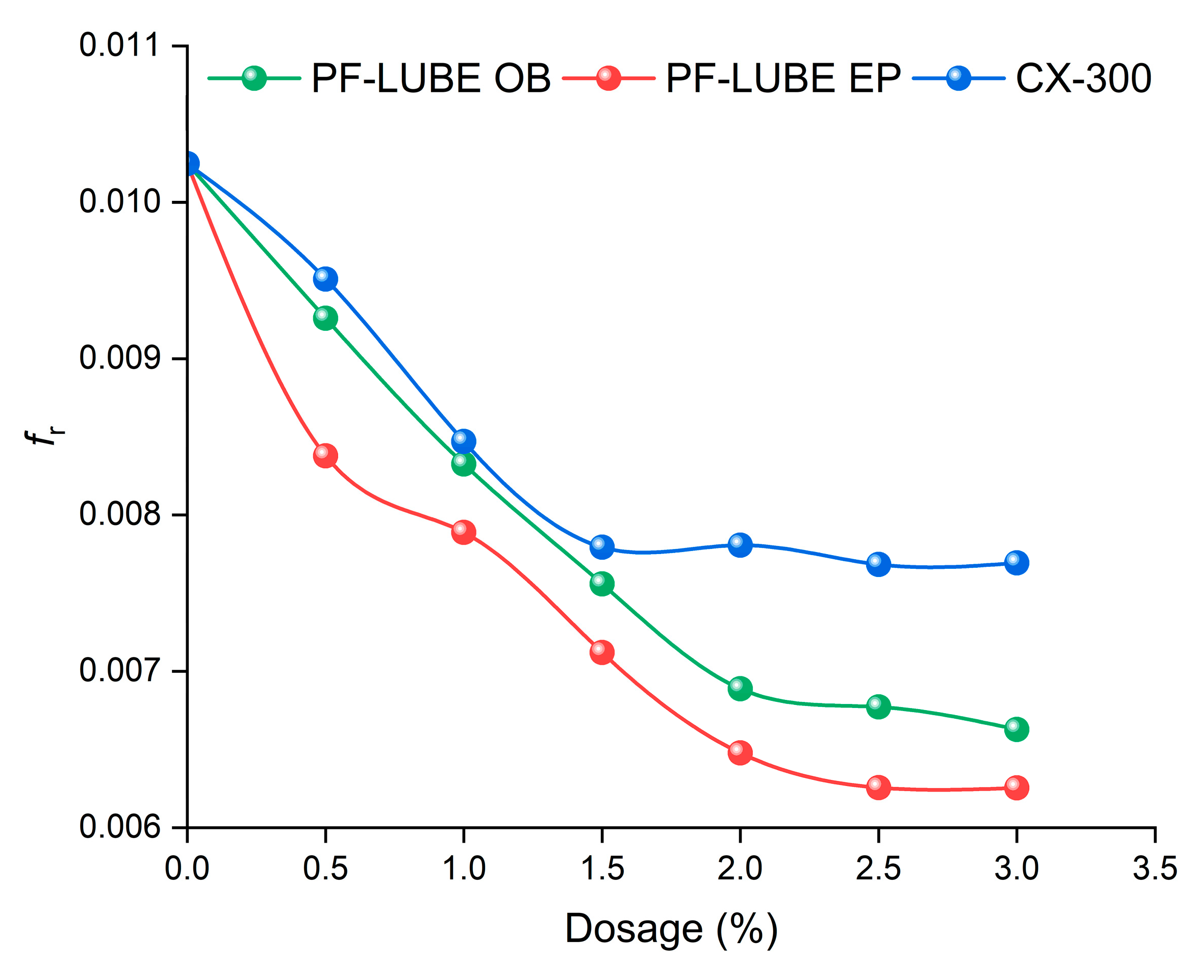
Figure 8.
Changes in the metal-rock friction coefficient under different load.

Figure 9.
Changes in the metal-rock friction coefficient under different formation.
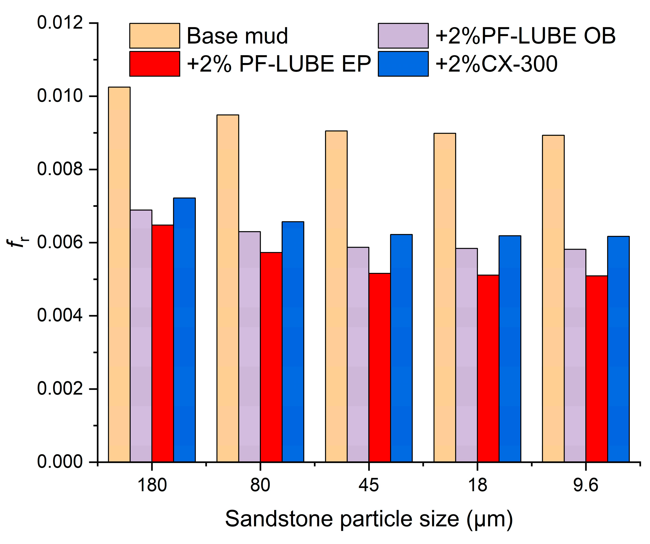
Figure 10.
Comparison of metal-mud cake interfacial friction coefficients of different lubricants.
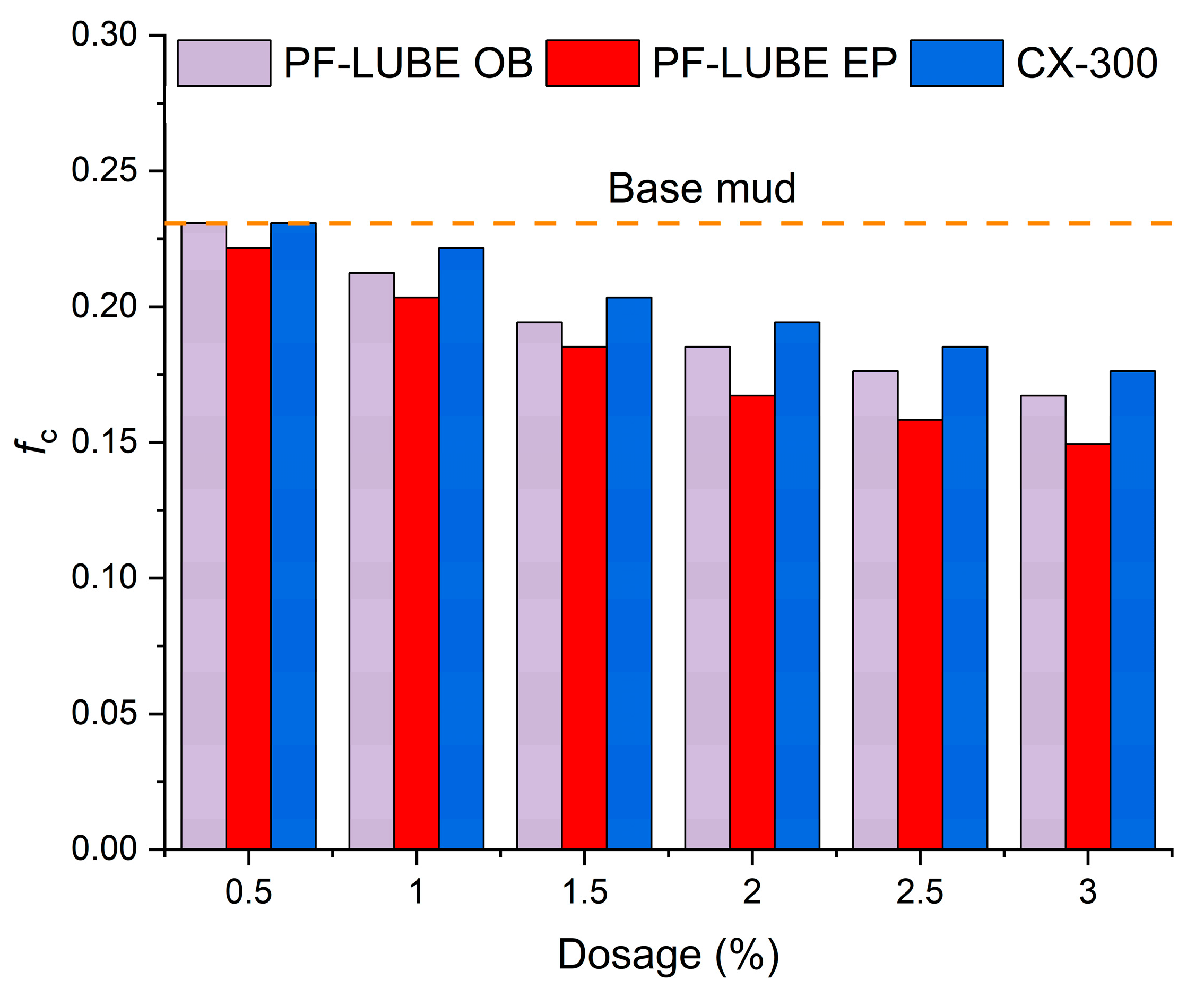
Figure 11.
Changes in the friction coefficient under different lubricants.
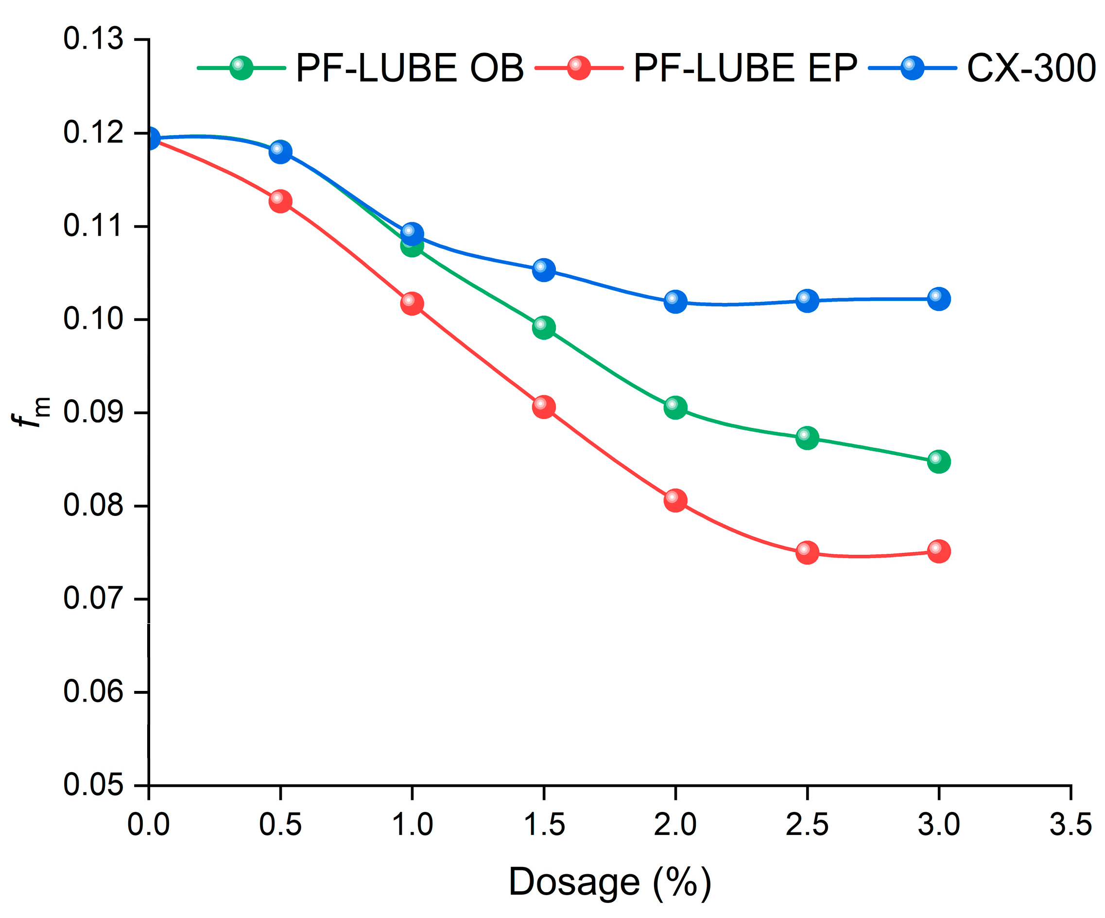
Figure 12.
Quantitative comparison of multi-interfacial friction coefficients of different lubricants.
Figure 12.
Quantitative comparison of multi-interfacial friction coefficients of different lubricants.
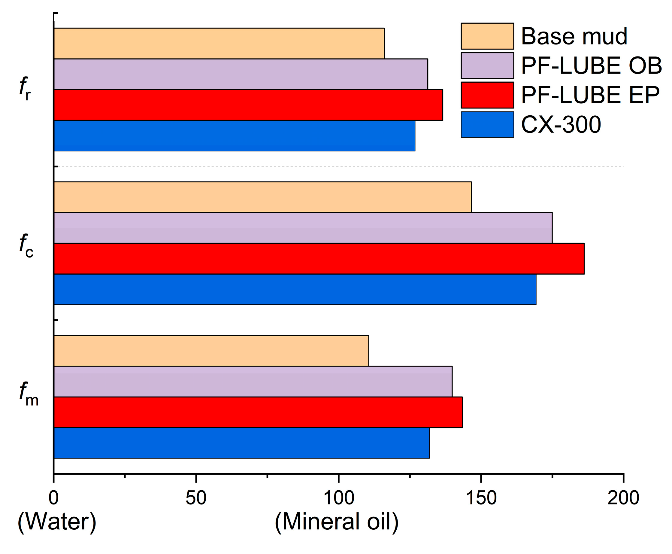
Figure 13.
Bionic sea anemone lubrication mechanism of PF-LUBE EP.
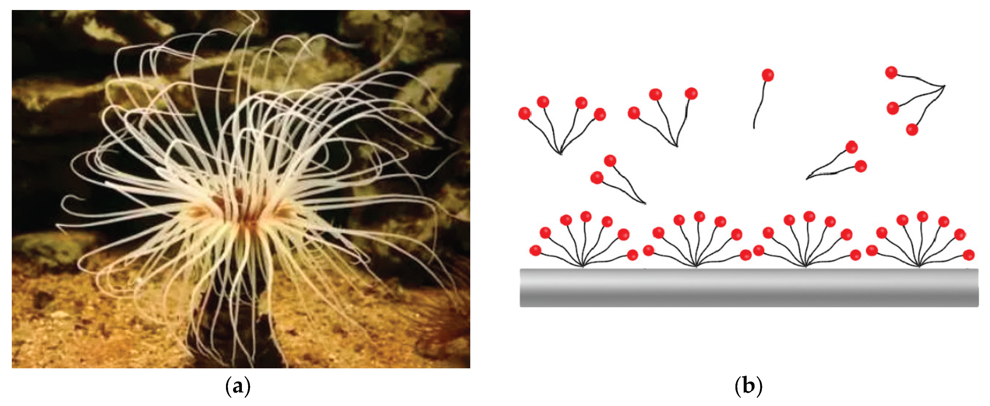

Table 1.
Influence of different lubricants on rheological properties of oil-based drilling fluids.
| Sample | Test time | AV(mPa·s) | PV(mPa·s) | YP(Pa) | 6/3 Reading |
|---|---|---|---|---|---|
| Base mud | BHR1 | 36 | 24 | 12 | 11/9 |
| AHR | 32 | 23 | 11 | 10/8 | |
| Base mud+ 2%PF-LUBE OB | BHR | 36 | 24 | 12 | 11/9 |
| AHR | 32 | 23 | 11 | 10/8 | |
| Base mud+ 2%PF-LUBE EP | BHR | 36 | 24 | 12 | 11/9 |
| AHR | 32 | 23 | 11 | 10/8 | |
| Base mud+ 2%CX-300 | BHR | 36 | 24 | 12 | 11/9 |
| AHR | 32 | 22 | 10 | 9/7 |
1 Hot rolling condition: 150℃ × 16h.
Table 2.
Influence of different lubricants on filtrate loss of oil-based drilling fluids.
| Sample | FLAPI2 | FLHTHP3 |
|---|---|---|
| Base mud | 1.0 | 3.6 |
| Base mud+ 2%PF-LUBE OB | 0.8 | 3.2 |
| Base mud+ 2%PF-LUBE EP | 0.8 | 3.2 |
| Base mud+ 2%CX-300 | 0.8 | 3.4 |
2 API condition: 25℃ × 0.7 MPa × 30 min. 3 HTHP condition: 150℃× 3.5 MPa × 30 min.
Table 3.
Influence of different lubricants on invasion depth of oil-based drilling fluids.
| Sample | Invasion depth(cm) 4 |
|---|---|
| Base mud | 2.4 |
| Base mud+ 2%PF-LUBE OB | 2.2 |
| Base mud+ 2%PF-LUBE EP | 2.2 |
| Base mud+ 2%CX-300 | 3.0 |
4 Test condition: 25℃ × 0.7 MPa × 30 min.
Disclaimer/Publisher’s Note: The statements, opinions and data contained in all publications are solely those of the individual author(s) and contributor(s) and not of MDPI and/or the editor(s). MDPI and/or the editor(s) disclaim responsibility for any injury to people or property resulting from any ideas, methods, instructions or products referred to in the content. |
© 2025 by the authors. Licensee MDPI, Basel, Switzerland. This article is an open access article distributed under the terms and conditions of the Creative Commons Attribution (CC BY) license (http://creativecommons.org/licenses/by/4.0/).
Copyright: This open access article is published under a Creative Commons CC BY 4.0 license, which permit the free download, distribution, and reuse, provided that the author and preprint are cited in any reuse.


