
Submitted:
20 June 2025
Posted:
24 June 2025
You are already at the latest version
Abstract
This study presents a numerical investigation into heart valve dynamics through a fluid–structure interaction (FSI) framework that incorporates biomagnetic blood flow and elastic arterial walls. The analysis focuses on the influence of magnetic field intensity—characterized by the Hartmann number (Ha)—and flow regime—defined by the Reynolds number (Re)—on critical hemodynamic parameters, including wall shear stress (WSS), velocity profiles, and pressure gradients in the valve region. Results demonstrate that stronger magnetic fields significantly stabilize intravalvular flow by suppressing recirculation zones and reducing flow separation distal to valve constrictions, offering protective hemodynamic benefits and serving as a non-invasive method to modulate vascular behavior and reduce the risk of cardiovascular pathologies such as atherosclerosis and hypertension.
Keywords:
fluid-structure Interaction (FSI)
; finite element method
; heart valves
; wall shear stress
; biomagnetic blood flow
; elastic walls
; hartmann number
; valve dynamics.
MSC: 35A15; 35-04; 35J65; 74-10; 74A10; 76-04; 76A05
1. Introduction
Cardiovascular diseases remain one of the leading causes of mortality worldwide, often linked to complex hemodynamic behaviors within arterial systems—particularly in regions of stenosis, bifurcation, or valve dysfunction [1,2,3]. Flow disturbances such as recirculation zones and oscillatory wall shear stress (WSS) have been implicated in endothelial dysfunction and atherogenesis [4,5]. A key contributor to these phenomena is the interaction between blood flow and the deformable arterial wall, formally treated as a fluid–structure interaction (FSI) problem [6,7,8,9].
Advances in computational biomechanics have enabled the use of fully coupled FSI models to simulate heart valve dynamics with greater accuracy. Borowski et al. [10] demonstrated that Arbitrary Lagrangian–Eulerian (ALE) methods improve the fidelity of valve deformation prediction in transcatheter aortic valve simulations. Kaiser et al. [11] employed an immersed boundary approach validated against 4D flow MRI, capturing realistic flow dynamics around pulmonary valves. Mao et al. [13] combined smoothed particle hydrodynamics with nonlinear finite elements to simulate coupled ventricular and valvular motion. These frameworks account for intricate interactions between pressure gradients, tissue motion, and geometric nonlinearity.
Beyond traditional hemodynamic considerations, there is growing clinical interest in the use of magnetic fields to modulate blood flow in cardiovascular applications. Given the weakly conducting nature of blood, external magnetic fields generate Lorentz forces that can dampen velocity fluctuations, suppress vortex formation, and enhance flow coherence. This is particularly relevant in heart valve regions, where shear-induced platelet activation, stagnation zones, and turbulent jets are common. These pathological flow features contribute to adverse outcomes such as thrombus formation, embolic risk, and accelerated bioprosthetic degeneration. By improving WSS uniformity and reducing peak stresses on the valve leaflets, magnetic modulation may offer a non-invasive therapeutic pathway to mitigate these risks and improve the functional longevity of both native and prosthetic valves [14,15].
Despite these promising insights, prior MHD studies have largely focused on rigid-walled arterial segments, simplified axisymmetric geometries, or steady-state flow assumptions. Very few incorporate realistic valve-adjacent conditions, let alone the dynamic FSI effects present in living tissues. The combined influence of magnetic field intensity (Hartmann number) and biomechanical compliance on flow-induced stress patterns remains underexplored. Furthermore, little is known about how magnetic fields might interact with leaflet motion or influence fatigue cycles in flexible valve supports. This study addresses these gaps by simulating magnetically influenced blood flow through a bifurcated, stenosed artery with elastic walls using a fully coupled ALE-based FSI framework. Our goal is to quantify how varying magnetic field strengths modulate flow separation, WSS, and wall displacement—thereby offering new computational insights into the design of magnetically augmented cardiovascular therapies [16,17].
This work contributes a novel perspective to the intersection of magnetohydrodynamics and cardiovascular biomechanics by providing the first fully coupled numerical simulation of biomagnetic blood flow through a bifurcated, stenosed geometry with compliant arterial walls. Unlike earlier studies that treat fluid and structure separately or assume simplified vessel mechanics, our model captures the nonlinear interplay between magnetic field intensity, flow separation, and elastic wall deformation using an Arbitrary Lagrangian–Eulerian (ALE) framework. The ability to systematically vary Hartmann and Reynolds numbers within this setting allows for controlled investigation of magnetic field effects on clinically relevant metrics such as wall shear stress (WSS), pressure gradients, and mechanical fatigue indicators. This work lays the groundwork for magnetically assisted flow modulation strategies in valve-adjacent regions and presents a computational platform that can be extended toward prosthetic valve optimization and thrombosis risk assessment.
The remainder of this paper is structured as follows: Section 2 develops the governing equations, outlining the ALE formulation for fluid–structure interaction under magnetic influence, along with constitutive models for both blood flow and arterial elasticity, and details the computational methodology, including domain geometry, boundary conditions. Section 3 presents a comprehensive analysis of the simulation results, examining the impact of varying Hartmann and Reynolds numbers on flow behavior, wall displacement, and WSS distribution. Finally, Section 4 summarizes the key findings, discusses implications for magnetically guided cardiovascular therapies, and outlines future directions for clinical translation and model refinement.
2. Mathematical Formulation
In this study, a two-dimensional, viscous, steady-state, incompressible laminar flow of a biomagnetic fluid is analyzed as it passes through a simplified representation of a heart valve. The computational domain reflects a symmetric valve geometry with a central constriction, mimicking the narrowing between deformable valve leaflets. It is assumed that the increase in effective viscosity due to the magnetic field is negligible and that the walls of the domain are electrically non-conductive, with no significant electric field effects present. The outer boundaries representing the vessel walls are modeled as linearly elastic, while the valve leaflets are treated as hyperelastic structures. The overall geometric configuration and the corresponding mesh used in the simulations are illustrated in Figure 2.
The blood, modeled as a Newtonian fluid, is assumed to be electrically conducting and is subjected to a transverse uniform magnetic field. A fully developed parabolic velocity profile is imposed at the inlet, whereas the outlet boundary is maintained at a fixed reference pressure, commonly set to zero. This setup provides a physiologically relevant approximation of flow conditions in the vicinity of the heart valve.
To effectively capture the coupled fluid–structure interactions inherent in such systems, the Arbitrary Lagrangian–Eulerian (ALE) framework is employed. This approach enables simultaneous treatment of fluid and solid domains by allowing mesh motion to be defined independently from both the material (Lagrangian) and spatial (Eulerian) frames. As such, ALE is particularly well-suited for simulating heart valve dynamics, where fluid motion interacts strongly with the deformable leaflet structures without prescribing a fixed mesh movement.
Considering the above assumption and methodology the governing equations in Arbitrary Lagrangian-Eulerian (ALE) formulation for fluid flow are given under, for more detail, see Donea et al. [19] and for monolithic ALE formulation of fluid structure interaction is given in Razzaq et al. [18]:
Conservation of mass
conservation of momentum
and are the dimensional velocity components and is the dimensional mesh coordinate velocity. is the electrical conductivity of the biomagnetic fluid. The fluid electric conductivity generates a term, , in Eq (11), representing the Lorentz force per unit volume.
The governing equations for the solid displacement in dimensional form is given by
Conservation of Momentum:
now, assuming that there is no external force acting on the solid body, i.e., .
where, h is the diameter of the artery and is the maximum velocity of the blood at the inlet. The dimensionless parameter and denote the Reynolds number and Hartmann number, respectively.
The eq (4) with the help of dimensionless parameters given in eq (5), can be written as:
where, is the strain tensor and in case of linearly elastic walls, the strain tensor can be written as:
here, J is the determinant value of F and F is defined as . Also the relation for second Piola-Kirchhoff stress tensor S with strain is, and , where E is Young’s modulus and is the Poisson ratio of solid wall and strain tensor is defined as:
By considering dimensionless parameter we can write eq 1-3 as:
The parabolic velocity profile is assumed at the inlet.
where, and outlet boundary conditions are prescribed on pressure. The pressure sets equal to zero at the outlet. On the interface of fluid and solid, regular no-slip boundary conditions are employed.
2.1. Geometrical Configuration
To provide anatomical context for the numerical investigation, Figure 1 presents a schematic of the human circulatory system, highlighting the pathways of deoxygenated and oxygenated blood through the heart chambers and major vessels. Of particular interest is the pulmonary valve and its adjacent vasculature, which play a central role in regulating blood flow from the right ventricle to the pulmonary artery. Although the true anatomy is three-dimensional and highly complex, this illustration helps orient the reader to the general flow direction and key anatomical landmarks relevant to the modeled domain.
A simplified two-dimensional representation of the valve region is employed in this study, as shown in Figure 2. This abstraction facilitates computational efficiency while capturing the essential structural and flow characteristics near the valve. The geometry consists of a constricted channel mimicking the narrowed orifice created by opposing valve leaflets, forming a stenosis-like throat region. The domain features symmetric, smoothly curved upper and lower boundaries that idealize the shape of valve leaflets in a planar section. The left side of the domain defines the inlet, where a fully developed parabolic velocity profile is prescribed, while the right side acts as the outlet. This configuration represents a cross-section of a valve chamber and includes gradual expansions upstream and downstream to model flow entrance and exit effects.
In this model, the vessel walls are treated as linearly elastic and isotropic, described using Young’s modulus E and Poisson’s ratio , capturing their relatively stiff mechanical response under flow-induced pressure loads. The material parameters used for the walls are:
In contrast, the leaflets are modeled using a Saint Venant–Kirchhoff (SVK) hyperelastic material model. While SVK is a relatively simple hyperelastic formulation—best suited for small to moderate deformations—it provides a nonlinear constitutive response needed for modeling valve leaflet flexibility under pulsatile flow. The material behavior is expressed in terms of the Lamé parameters and , which relate to E and through:
It is important to note that while the SVK model allows for some degree of nonlinear elastic response, it is most accurate under moderate strain levels. For small-deformation static studies such as this, it offers a reasonable compromise between simplicity and capturing the essential mechanical effects of leaflet flexibility.
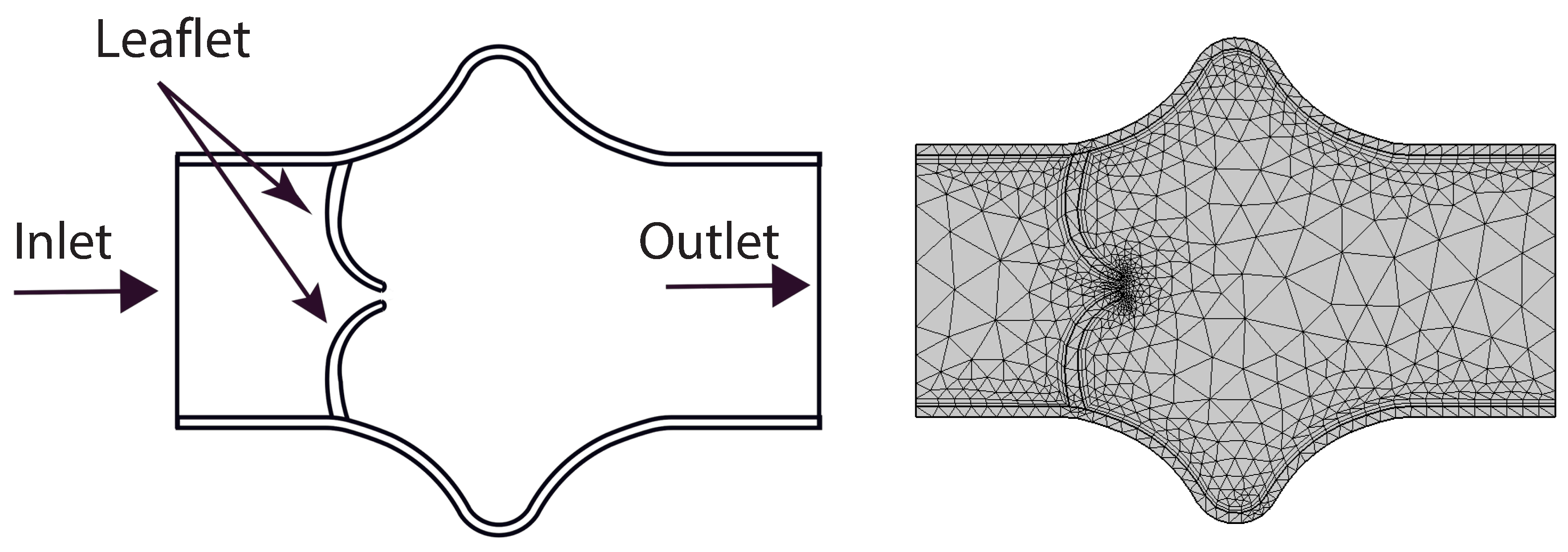
Figure 2.
Simplified 2D geometry of the heart valve region with symmetric, stenosis-like configuration and coarse mesh.
Figure 2.
Simplified 2D geometry of the heart valve region with symmetric, stenosis-like configuration and coarse mesh.
The initial coarse mesh is depicted in Figure 2, where a triangular discretization is employed to partition the computational domain into a finite number of elements. This coarse configuration consists of 1303 triangular elements. A detailed summary of mesh refinement levels—including the number of elements, the total wall shear stress (WSS) on the lower elastic boundary, and the corresponding absolute WSS error—is provided in Table 1. All simulations presented in this study are conducted using the mesh at refinement Level 4, which corresponds to 25,545 degrees of freedom.
3. Results and Discussion
In this section, we present and analyze the numerical results obtained from the fluid–structure interaction simulations of blood flow under the influence of an external magnetic field. The effects of varying Hartmann numbers are examined for different Reynolds numbers . The results focus on flow velocity, wall displacement, wall shear stress (WSS), and the general hemodynamic response under magnetic field influence.
3.1. Velocity Field Analysis
The numerical simulations present a comprehensive picture of intravalvular blood flow through a stenosed valve model subjected to various Hartmann numbers (Ha) and Reynolds numbers (Re), as shown in Figure 3, Figure 4 and Figure 5. The velocity fields were obtained from stationary fluid–structure interaction (FSI) computations on a two-dimensional domain resembling a simplified heart valve geometry with flexible leaflets and elastic walls. A parabolic inlet flow was prescribed, mimicking physiologically relevant conditions in the absence of pulsatility.
In the baseline case (Ha = 0), the velocity distribution demonstrates strong flow acceleration through the throat region due to geometric narrowing. Downstream of the stenosis, a pair of well-defined vortices emerge symmetrically near the leaflet tips, accompanied by a noticeable drop in core velocity and widening of low-velocity recirculation zones. These patterns are more pronounced at higher Reynolds numbers, where inertial effects dominate over viscous dissipation, leading to intensified flow separation and longer wake regions. The presence of these vortices is indicative of adverse pressure gradients and shear layer instability typically observed in pathological or prosthetic valvular configurations.
As the magnetic field intensity increases (Ha = 8, 10, 12), the velocity field exhibits a progressive suppression of flow separation and damping of recirculation zones. This is attributed to the Lorentz force generated by the imposed magnetic field, which acts as a momentum sink, introducing an effective damping mechanism. The Lorentz force resists lateral deviations of flow, promoting alignment along the axial direction and mitigating rotational structures. At lower Re (e.g., Re = 400), the magnetic field is highly effective in stabilizing the flow, nearly eliminating recirculation zones at moderate Ha values. At higher Re (e.g., Re = 1200), the inertia of the fluid is stronger, requiring correspondingly higher Ha values to achieve the same degree of stabilization, but the trend remains consistent.
Additionally, the velocity magnitude profiles near the leaflet tips show an observable reduction in peak jet velocity with increasing Ha. This attenuation is associated with an increased effective viscosity due to magnetic damping, leading to broader and more uniform velocity contours across the channel. The core jet narrows less dramatically, and velocity gradients near the wall and leaflet surfaces become smoother. This has significant biomechanical implications, especially regarding shear stress and its influence on endothelial integrity, blood element activation, and mechanical loading on the leaflet surfaces.
The observed velocity patterns highlight the interplay between inertial, viscous, and magnetic forces in shaping the hemodynamics of valvular flow. In the absence of magnetic influence, the velocity field reflects classic features of post-stenotic flow: jet acceleration through the throat, followed by separation, recirculation, and vortex shedding. These are pathological hallmarks in diseased valves and are often associated with hemolysis, platelet activation, and tissue degeneration due to elevated shear stresses and oscillatory flows.
The introduction of magnetic fields alters this behavior substantially. The suppression of vortices and stabilization of the flow field is particularly beneficial in mitigating shear-related damage and promoting hemodynamic efficiency. In essence, the magnetic field behaves as an active flow control mechanism, analogous to mechanical or geometric flow stabilizers but with the advantage of being externally tunable and non-invasive.
These findings align well with established principles of magnetohydrodynamics in biological flows and extend prior studies by demonstrating the effect within a coupled FSI framework. Importantly, the model incorporates deformable leaflet and wall boundaries, thereby capturing secondary interactions between fluid motion and structural deformation. Although a stationary formulation was adopted, the trends are expected to persist under transient flow regimes.
From a clinical or device-design perspective, the results suggest that magnetic field application could be employed as a passive stabilization strategy in valve prostheses or bio-hybrid systems, potentially prolonging device lifespan and reducing adverse flow-induced phenomena. Future work should consider full transient simulations and pulsatile inflow conditions to extend the current conclusions, and experimental validation would be essential to quantify the practical thresholds of magnetic field strengths in physiological settings.
3.2. Arterial Wall Displacement
The interaction between fluid flow and the elastic vessel wall is further assessed through the displacement of the upper wall, as shown in Figure 6. In the case of zero magnetic field, the deformation is significantly higher, particularly at the post-stenotic region, where high-velocity jets impinge on the wall.
When the magnetic field is applied, the Lorentz force reduces the flow momentum, thereby decreasing the fluid pressure on the wall. Consequently, the displacement magnitude is reduced across the entire upper wall. This effect is more significant near the bifurcation and downstream of the stenosis, where flow-induced forces are usually high.
Reduced displacement implies less wall fatigue and a lower risk of damage due to excessive mechanical stress. It also suggests that magnetic regulation could offer protective biomechanical benefits in arteries with compromised elasticity.
3.3. Pressure
The pressure plots shown in Figure 7 illustrate the centerline pressure distribution obtained under varying Hartmann (Ha) and Reynolds (Re) numbers. These simulations are conducted within a stationary framework to capture the pressure field resulting from the interaction between blood flow and valve leaflet deformation. Each subplot corresponds to a specific Reynolds number (Re = 400, 800, 1200), while curves within each plot represent different Hartmann numbers (Ha = 0, 4, 8, 12). As the Reynolds number increases, the inertial forces in the flow become more dominant, leading to sharper pressure gradients, particularly downstream of the valve region. The pressure consistently decreases along the flow direction, indicative of forward flow through a constricted passage such as a heart valve.
The effect of the magnetic field, represented by the Hartmann number, is clearly evident in the flattening of the pressure profiles as Ha increases. At higher Hartmann numbers, the pressure drop becomes more gradual due to the magnetic damping effects, which suppress flow instabilities and reduce velocity gradients. This behavior suggests a stabilizing influence of the magnetic field on the flow, resulting in a more uniform pressure distribution. In the context of cardiovascular applications, such as artificial or bio-prosthetic heart valves, this reduction in pressure fluctuation may translate into lower mechanical stresses on the valve leaflets. Consequently, incorporating magnetohydrodynamic effects in the design or operation of heart valve systems could potentially enhance their durability and functional performance.
3.4. Wall Shear Stress (WSS) Distribution
Figure 8 and Figure 9 show the distribution of wall shear stress (WSS) over the entire surface of the upper and lower heart valve leaflets. WSS is a critical biomechanical stimulus influencing endothelial function and the progression of valve related pathologies. The magnitude and spatial variation of WSS are key indicators of the mechanical environment experienced by the valve tissue.
In the baseline configuration without magnetic influence ($Ha = 0$), WSS exhibits significant spatial variation across the leaflet surface. The face of the leaflet directly exposed to the bloodstream experiences relatively high shear stress due to stronger flow interaction, while the back face, shielded from direct flow, is subjected to much lower WSS. Notably, a sharp peak in WSS is observed at the leaflet tip, where the geometry induces strong flow acceleration and shear concentration.
With increasing magnetic field strength, the WSS distribution becomes more uniform, and the magnitude increases especially in regions that initially experienced low shear, such as the back face of the leaflet. The peak at the leaflet tip becomes broader but less sharp, indicating a stabilizing effect on the shear field. These trends suggest that magnetic modulation not only smoothens the flow but also redistributes mechanical loading more evenly across the leaflet, potentially mitigating localized stress concentrations and reducing the risk of mechanical fatigue or endothelial damage.
4. Conclusions
This study presents a detailed numerical analysis of heart valve dynamics using a fluid–structure interaction (FSI) framework incorporating biomagnetic effects. By employing an Arbitrary Lagrangian–Eulerian (ALE) formulation, the model captures the coupled behavior of blood flow and deformable valve-like elastic walls under various magnetic field strengths, represented by the Hartmann number (Ha).
The results demonstrate that increasing the magnetic field intensity has a significant stabilizing influence on intravalvular flow. Specifically, higher Hartmann numbers suppress recirculation zones and flow separation downstream of the constriction, promoting smoother, more aligned velocity fields. This effect is particularly relevant in valve regions, where disturbed flow patterns contribute to shear-induced damage, thrombogenic risks, or calcific degeneration.
In addition, the simulations reveal that magnetic fields attenuate wall displacement and dampen fluid-induced oscillations of the valve structure. This suggests potential benefits in terms of reducing mechanical fatigue and prolonging the functional lifespan of biological or prosthetic valve tissues.
Furthermore, the pressure distribution along the centerline shows a consistent decrease in pressure downstream, with the magnitude of pressure drop moderated by increasing Hartmann numbers. At higher magnetic intensities, the damping effect leads to smoother pressure gradients, reducing localized pressure spikes that could otherwise contribute to mechanical stress and fatigue in valve structures. These findings support the hypothesis that magnetic modulation not only stabilizes flow velocity but also results in a more favorable pressure profile within the valve domain.
Critically, the wall shear stress (WSS) distribution becomes more uniform and increases in magnitude with stronger magnetic fields. Since abnormal WSS has been linked to valvular endothelial dysfunction and disease progression, the findings imply that controlled magnetic exposure could have protective hemodynamic effects in heart valve environments.
While idealized geometries were used to approximate heart valve behavior, the fundamental insights gained support the concept of magnetically modulated flow as a therapeutic or assistive strategy in cardiovascular devices. Future work should aim to integrate realistic valve morphologies, pulsatile flow conditions, and patient-specific boundary data to more accurately represent native or prosthetic valve mechanics.
Overall, this work highlights the potential role of magnetic field manipulation in modulating heart valve hemodynamics, reducing pathological flow features, and improving long-term biomechanical outcomes in valvular heart disease.
Acknowledgments
The authors gratefully acknowledge the financial support of the Deutsche Forschungsgemeinschaft (DFG, German Research Foundation) under the funding reference, GZ: FIP 61/1 - 2024 (Project Number: 528740160).
Conflicts of Interest
The authors declared that there was no conflict of interest in this study.
References
- Caro, C. G., Fitz-Gerald. Atheroma and arterial wall shear observation, correlation and proposal of a shear dependent mass transfer mechanism for atherogenesis. In Proceedings of the Royal Society of London B: Biological Sciences. 1971. 177(1046): 109-133.
- Iqbal K, Rossi di Schio E, Anwar MA. A Fluid–Structure Interaction Analysis to Investigate the Influence of Magnetic Fields on Plaque Growth in Stenotic Bifurcated Arteries. Dynamics 2024, 572–591. [Google Scholar] [CrossRef]
- DeBakey, M. E., Lawrie. Patterns of atherosclerosis and their surgical significance. Annals of surgery 1985, 201, 115. [Google Scholar] [CrossRef] [PubMed]
- Ku, D. N., Giddens. Pulsatile flow and atherosclerosis in the human carotid bifurcation. Positive correlation between plaque location and low oscillating shear stress. Arteriosclerosis, thrombosis, and vascular biology 1985, 5, 293–302. [Google Scholar] [CrossRef] [PubMed]
- Malek, A. M., Alper. Hemodynamic shear stress and its role in atherosclerosi. Jama 1999, 282, 2035–2042. [Google Scholar] [CrossRef] [PubMed]
- Stroud, J. S., Berger. Numerical analysis of flow through a severely stenotic carotid artery bifurcation. Journal of Biomechanical Engineering 2002, 124, 9–20. [Google Scholar] [CrossRef] [PubMed]
- Razzaq, M.; Anwar, M.A.; Iqbal, K.; Gurris, M. Investigation of Fluid–Structure Interaction in Stenosed Bifurcated Arteries: Flow Dynamics and Conjugate Heat Transfer. Mathematics 2025, 13, 1637. [Google Scholar] [CrossRef]
- Tzirtzilakis, E. E. A mathematical model for blood flow in a magnetic field. Physics of fluids 2005, 17, 077103. [Google Scholar] [CrossRef]
- Anwar MA, Iqbal K, Razzaq M. Analysis of biomagnetic blood flow in a stenosed bifurcation artery amidst elastic walls. Physica Scripta 2021, 96, 085202. [Google Scholar] [CrossRef]
- Borowski, M., de Vecchi. Comparison of FEA and FSI simulations of transcatheter aortic valve replacements. Current Directions in Biomedical Engineering 2018, 4, 511–514. [Google Scholar]
- Kaiser, T., Koch; et al. Validation of pulmonary valve hemodynamics in an immersed boundary fluid–structure interaction model using 4D flow MRI. Annals of Biomedical Engineering 2023. [Google Scholar] [CrossRef]
- Turabi, A., Sadiq; et al. Magnetohydrodynamic study of hybrid nanofluids in stenosed arteries under inflammatory conditions using finite element modeling. Innovative Infrastructure Solutions 2025. [Google Scholar] [CrossRef]
- Mao, W., Caballero. Fully coupled fluid–structure interaction simulation of the aortic and mitral valves in a realistic 3D left ventricle model. PLoS ONE 2017, 12, e0184729. [Google Scholar] [CrossRef] [PubMed]
- Dresp, J., Schmid-Schönbein. Electromagnetic fields and cardiovascular disease: Influence on hemodynamics and endothelial function. Frontiers in Cardiovascular Medicine 2020, 7, 611764. [Google Scholar] [CrossRef]
- Uddin, M. J., Rahman. Modelling of coronary artery stenosis and study of hemodynamic under magnetic field. Procedia Engineering 2015, 105, 306–312. [Google Scholar] [CrossRef]
- Cherkaoui, I., Asgari. Toward a mesoscopic modeling approach of magnetohydrodynamic blood flow in pathological vessels: A comprehensive review. Annals of Biomedical Engineering 2023, 51, 2415–2440. [Google Scholar] [CrossRef] [PubMed]
- Siddiqui, A. M., & Shah. The effect of magnetic field on blood flow through stenotic artery: A review on bio-magnetic fluid dynamics. Journal of Magnetism and Magnetic Materials 2013, 345, 123–137. [Google Scholar] [CrossRef]
- Razzaq, M.; et al. "Numerical simulation of fluid-structure interaction with application to aneurysm hemodynamics." Fluid-Structure Interaction. Theory, Numerics and Applications pp. 283– 294 Herrsching am Ammersee, 29.9.-1.10.2008.
- Donea, Jean, et al. "Arbitrary L agrangian–E ulerian Methods." Encyclopedia of Computational Mechanics Second Edition (2017): 1-23.
Figure 1.
Diagram of circulatory system with focus on pulmonary valve region. Adapted from biorender.com.
Figure 1.
Diagram of circulatory system with focus on pulmonary valve region. Adapted from biorender.com.
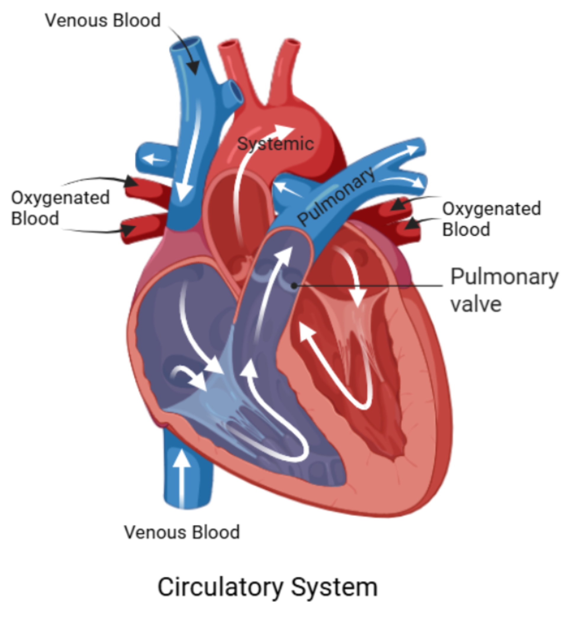
Figure 3.
Velocity field for at different Hartmann numbers: top to bottom, Ha=0, Ha=8, Ha=10, Ha=12.
Figure 3.
Velocity field for at different Hartmann numbers: top to bottom, Ha=0, Ha=8, Ha=10, Ha=12.
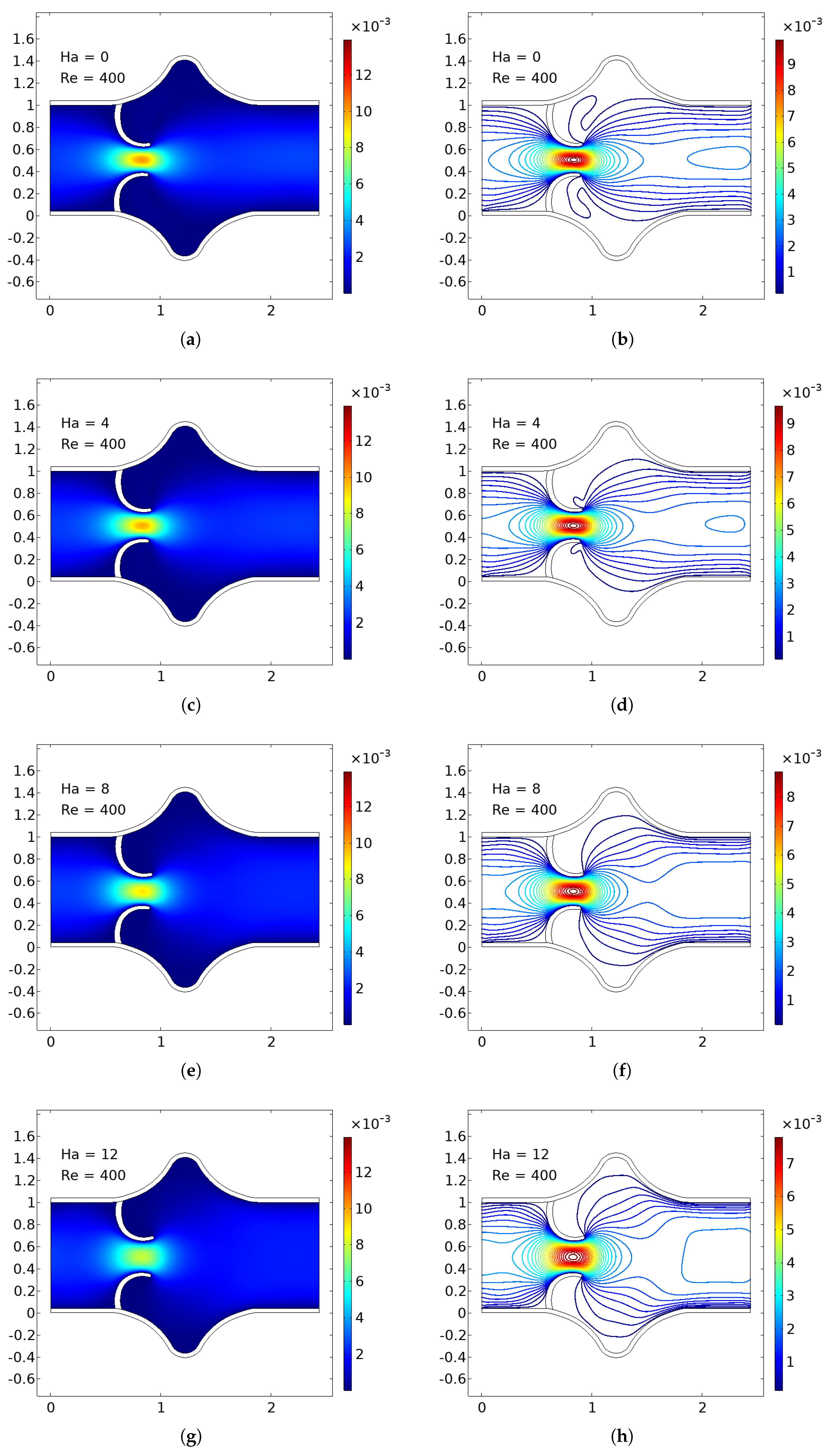
Figure 4.
Velocity field for at different Hartmann numbers: top to bottom, Ha=0, Ha=8, Ha=10, Ha=12.
Figure 4.
Velocity field for at different Hartmann numbers: top to bottom, Ha=0, Ha=8, Ha=10, Ha=12.
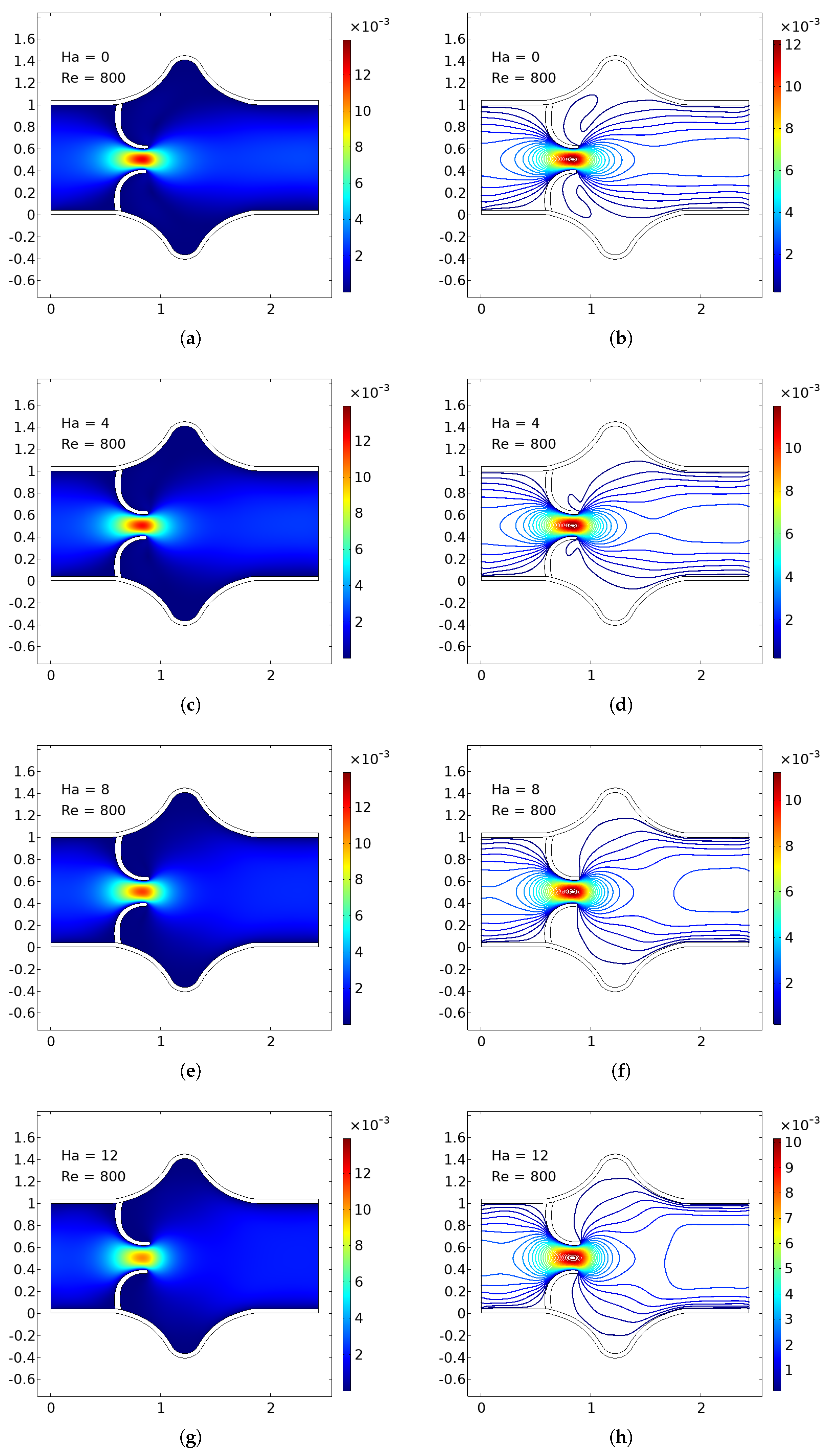
Figure 5.
Velocity field for at different Hartmann numbers: top to bottom, Ha=0, Ha=8, Ha=10, Ha=12.
Figure 5.
Velocity field for at different Hartmann numbers: top to bottom, Ha=0, Ha=8, Ha=10, Ha=12.
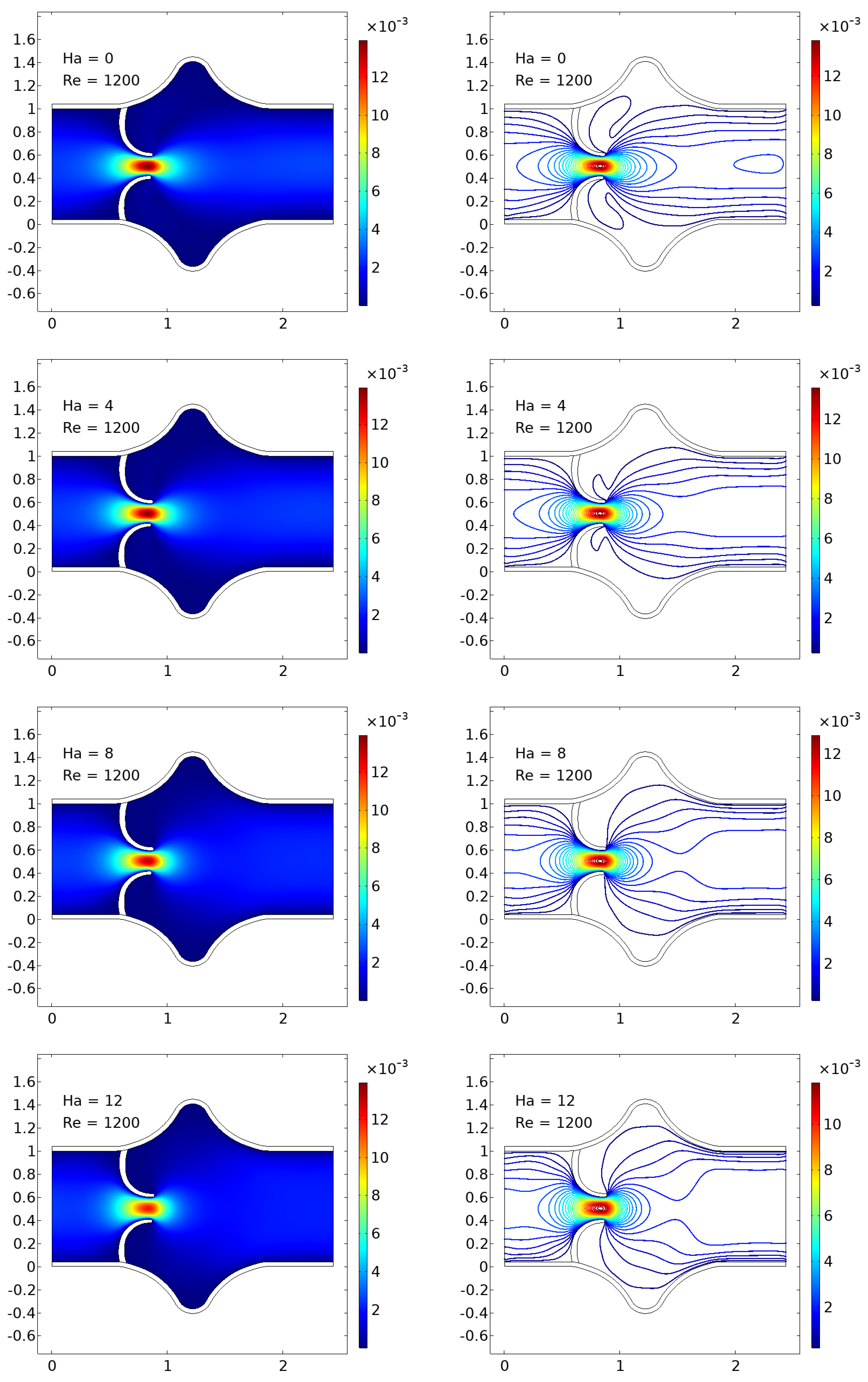
Figure 6.
Total displacement of the upper elastic arterial wall for various Hartmann and Reynolds numbers.
Figure 6.
Total displacement of the upper elastic arterial wall for various Hartmann and Reynolds numbers.
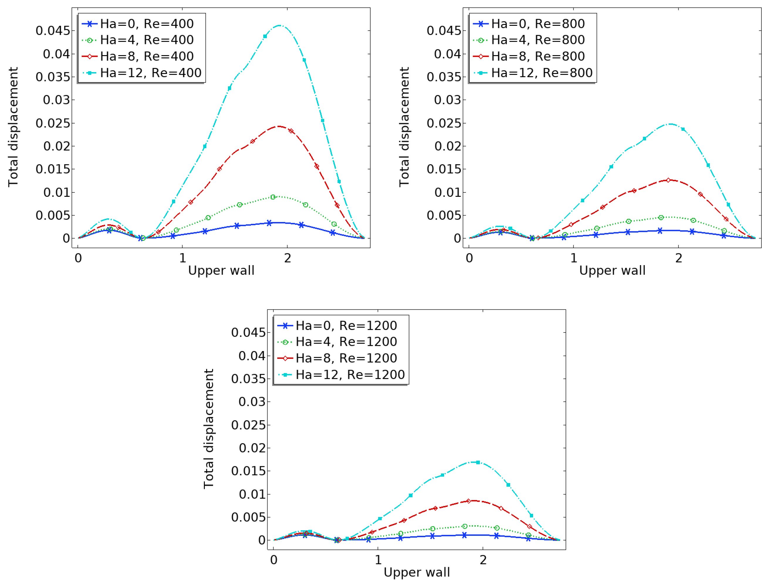
Figure 7.
Pressure computed at the center-line for various Hartmann and Reynolds numbers.
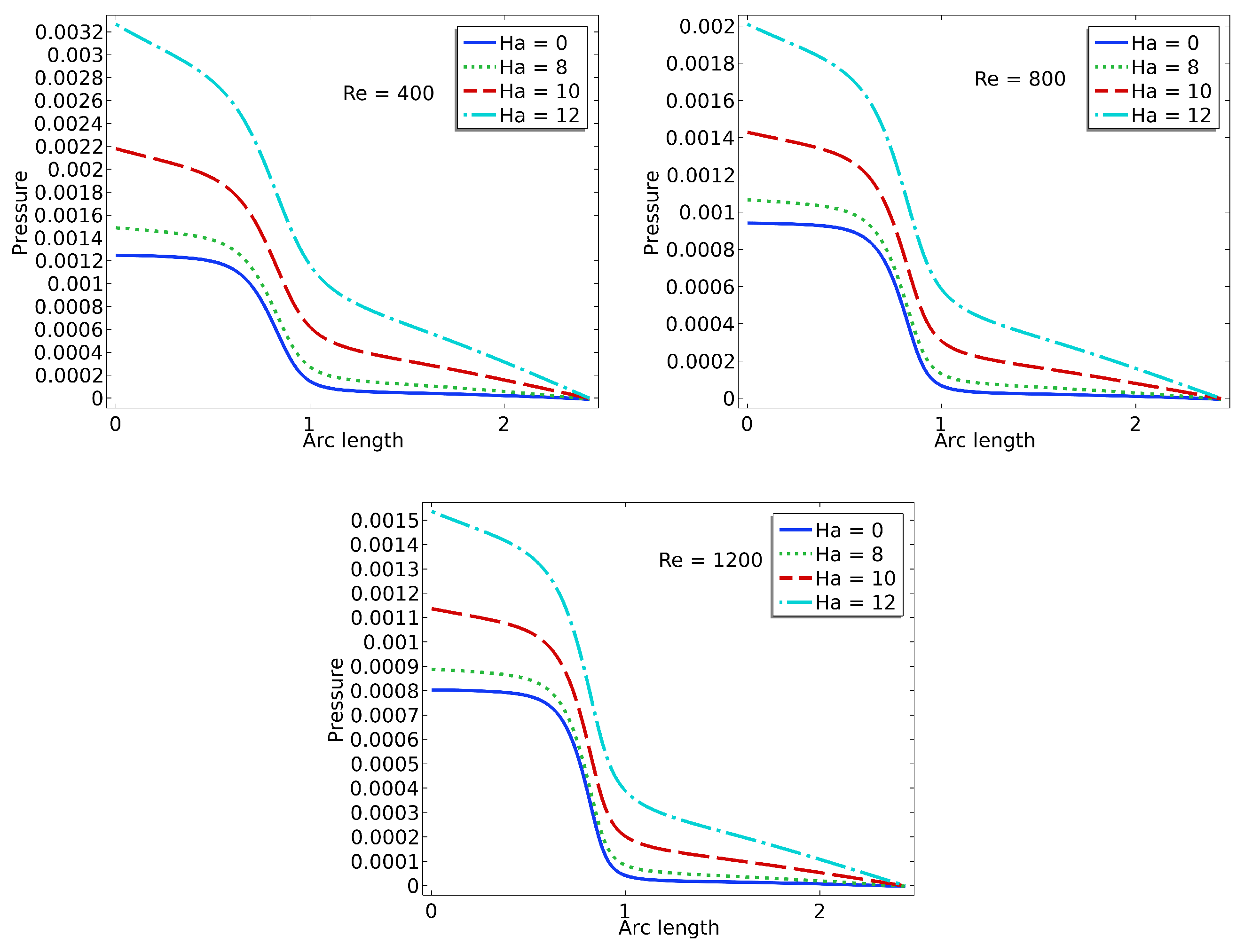
Figure 8.
Wall shear stress on upper leaflet.
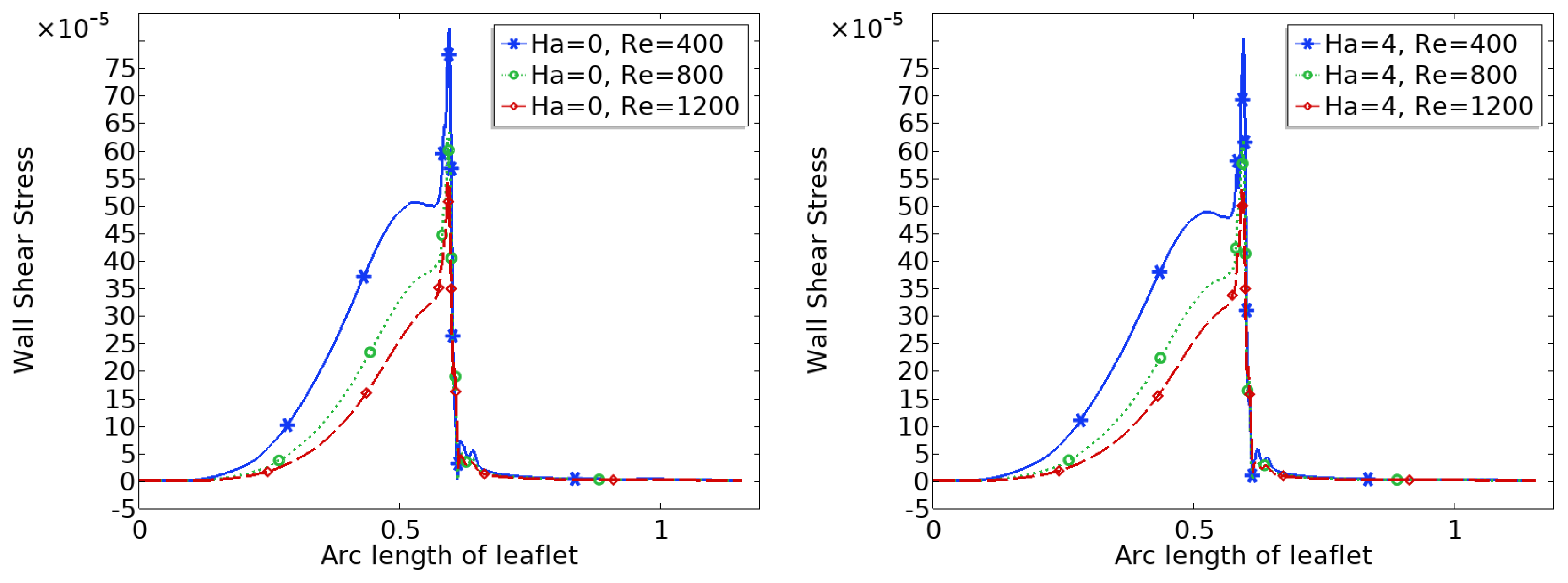
Figure 9.
Wall shear stress on upper leaflet.
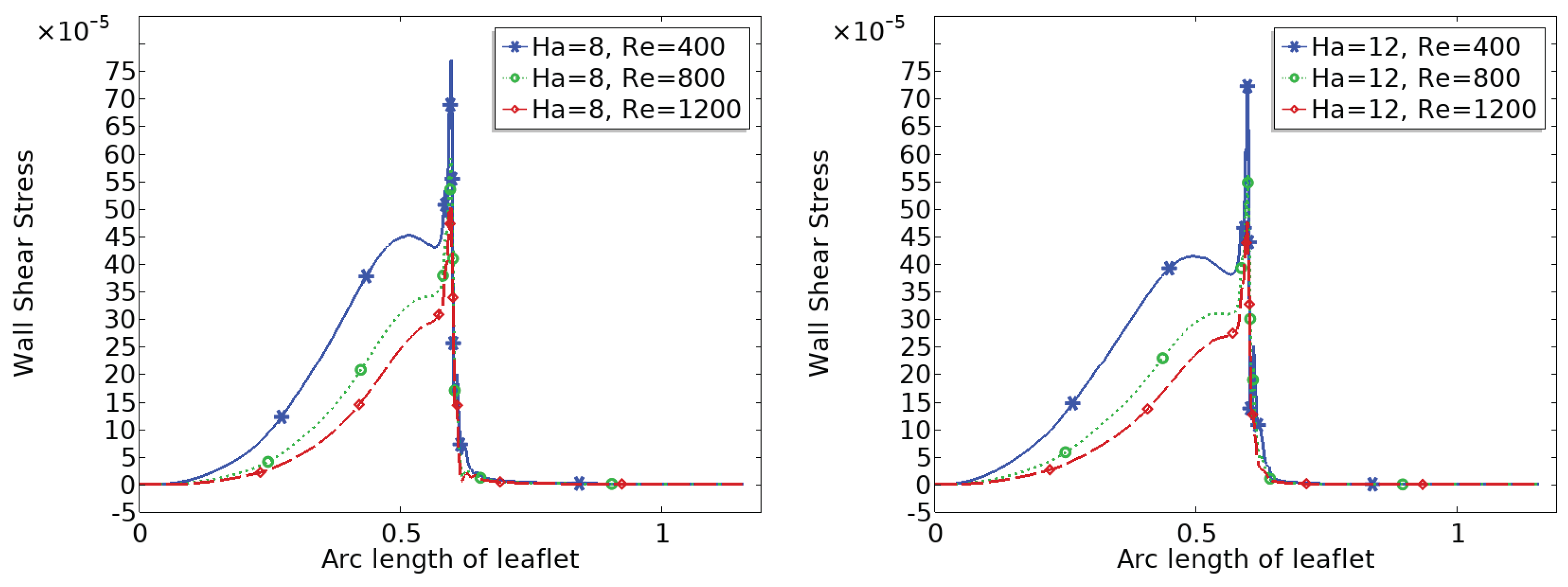

Table 1.
The mesh refinement levels with the number of elements and wall shear stresses
| Level | No of elements | Total WSS on lower wall | Absolute error |
|---|---|---|---|
| 0 | 1303 | 0.1483 | - |
| 1 | 1467 | 0.1532 | 0.0049 |
| 2 | 4087 | 0.1521 | 0.0011 |
| 3 | 9519 | 0.1561 | 0.0034 |
| 4 | 25545 | 0.1579 | 0.0018 |
| 5 | 28049 | 0.1578 | 0.0001 |
Disclaimer/Publisher’s Note: The statements, opinions and data contained in all publications are solely those of the individual author(s) and contributor(s) and not of MDPI and/or the editor(s). MDPI and/or the editor(s) disclaim responsibility for any injury to people or property resulting from any ideas, methods, instructions or products referred to in the content. |
© 2025 by the authors. Licensee MDPI, Basel, Switzerland. This article is an open access article distributed under the terms and conditions of the Creative Commons Attribution (CC BY) license (http://creativecommons.org/licenses/by/4.0/).
Copyright: This open access article is published under a Creative Commons CC BY 4.0 license, which permit the free download, distribution, and reuse, provided that the author and preprint are cited in any reuse.


