
Submitted:
18 June 2025
Posted:
24 June 2025
You are already at the latest version
Abstract
The Bric-a-Brick project aims to transform the role of the bricklayer by focusing on ergonomics and human-machine collaboration. By merging human expertise with robotics, the authors of the paper present a cost-effective prototype that aims to reduce the safety risks associated with part of the work of the regular bricklayer and cut down the future prospects of musculoskeletal disorders that are commonly associated with this profession. The Bric-a-Brick project aims to reach, by December 31, 2026, Technology Readiness Level 9 (TRL 9): a full technological maturity for implementation in real-world environments. To achieve this goal, Bric-a-Brick was developed as a promising intermediate validation activity. While the current system is still under development and much is yet to be achieved, initial results demonstrate strong potential. Further refinement is expected to enhance its future reliability and effectiveness.
Keywords:
high payload cobots
; ergonomics
; construction industry
; computer vision
1. Introduction
The construction industry stands at a critical juncture, both in terms of its economic significance and its environmental impact. Currently, it is responsible for approximately 35% [1] of global energy-related emissions, highlighting its substantial carbon footprint. Economically, the sector contributes around 14% to global GDP [2] and is projected to grow significantly, reaching an estimated value of $17.5 trillion by 2030 [3].
Despite this growth potential, the industry faces several major challenges. A global survey conducted by ABB in 2021, involving 1900 construction businesses across Europe, the US, and China, revealed a widespread skills shortage, with 91% of respondents anticipating a labor crisis within the next decade. Nearly half (44%) of these businesses are already struggling to recruit qualified workers [4]. In parallel, improving health and safety on construction sites and addressing environmental concerns were each identified as priorities by 42% of respondents, suggesting that workforce well-being and sustainability are becoming central to future industry strategies [5].
In 2017, the McKinsey Global Institute (MGI) published a well-known report titled Reinventing Construction: A Route to Higher Productivity [6]. This report highlights the significant productivity gap in the construction industry compared to other sectors (The Economist has elegantly re-presented the metric in the chart at Figure 1). Productivity growth in construction has been stagnant for decades, with labor productivity increasing by just 1% per year over the past 20 years — far below the 2.8% annual growth observed in other industries. From 1950 to 2010, in the United States, labor productivity in construction has declined since 1968, in contrast to its rise in other sectors: agriculture, manufacturing and retail [6].
In response to these challenges, there is growing interest in the adoption of robotics and automation [7]. While currently only 55% of construction companies report using robotic technologies — compared with 84% in the automotive industry and 79% in manufacturing — 81% of respondents indicated they plan to either introduce or expand automation in the coming years [5].
The adoption of automation and robotics technologies is, nonetheless, very dependent on the scale of the construction site. Advanced tools enable better planning, real-time monitoring, and precise execution, which are important requirements of major infrastructure projects, but are less ready to promise the same levels of advancement for limited-scale, bespoke interventions.
In fact, unlike large-scale, repetitive industrial environments where processes and tasks are highly standardized, small construction projects are characterized by low repeatability and high variability in the work to be performed. These types of construction sites - usually involving minor building works like residential renovations, commercial fit-outs, small home builds, extensions, or repairs - are for these authors to be taken as a benchmark, since they present a unique set of challenges that make the automation barrier extremely challenging to surpass.
Apart from reducing efficiency gains and increasing operational complexity, traditional automation is cost-prohibitive and demands high-skilled workers in the domain of automation engineering and robotics. In fact, whether the solution is offered by the integration of industrial robots with high payloads on tele-operated or autonomously-guided vehicles [8,9,10] as in Figure 2, or their placement on platforms and linear tracks to augment calibration accuracy [11] as in Figure 3 and automate repetitive high-load tasks, it is difficult to use them in small-scale operations, without an extensive and costly logistic infrastructure.
Many tasks on small sites require manual dexterity, problem-solving, and on-the-spot adaptation, which are hard to automate without a very skilled workforce. While automation technologies help manage infrastructural, large-scale projects efficiently by streamlining workflows (as an example, structural archs placement in tunnels [12] as in Figure 4 or rebar placement in bridges [13] as in Figure 5), improving project coordination, and reducing operational delays, the non-repetitive nature of tasks to undertake in small construction sites means workers must be skilled across multiple disciplines, yet training for this kind of versatility is both time-consuming and very costly.
To ensure the same productivity levels while ensuring assignment adaptability and that safety standards are met, machines and robots should constantly conform to new conditions, layouts, and obstacles, which significantly complicates job automation [14,15]. In practice, every project requires tailored adjustments, and automated equipment must be capable of understanding and navigating complex, unpredictable scenarios. This is obviously quite unlike a factory assembly line, where robots perform the same movements repeatedly in a controlled, predictable setting. Unlike a smooth factory floor, these sites often feature uneven terrain, debris, variable lighting, and constantly changing conditions due to ongoing construction activities.
For these reasons, construction companies generally employ skilled manual workforce of around 15 workers or fewer and demand often productivity levels at the expense of safety requirements, in order to meet cost-effectiveness and shorter timelines - weeks to few months - for job completion. A large portion of the current construction workforce in Europe is nearing retirement age and there’s a lack of younger workers entering the trades to replace them. Physical demands, safety risks, the consequent lack of gender, age, and disability inclusivity is more and more deterring younger generations from considering construction as a viable career path.
What is more, musculoskeletal disorders (MSDs) are the most common work-related health issue in the EU, affecting workers across all sectors and causing significant costs to enterprises and society [16]. Jobs with higher MSD risks, the so so-called "3-D jobs" (dirty, dangerous and demanding), are found particularly in the agriculture and horticulture, construction, health care, household, transport and food sectors.
In response, EU-OSHA launched a 4-year research initiative in 2017 aimed at addressing MSDs. The initiative’s goals include improving policy instruments at both EU and national levels, enhancing MSD prevention and management in workplaces, sharing successful practices, supporting national measures for workplace prevention, promoting the reintegration of workers with MSDs, and identifying research priorities to better understand the causes of MSDs.
One of the study’s conclusions is that the integration of ergonomic principles into product and process design plays a pivotal role in fostering effective and safe human-machine cooperation. Ergonomic design seeks to adapt systems to human capabilities and limitations, ensuring that workers interact with machines in ways that promote safety, comfort, and efficiency "by design".
Bric-a-Brick suggests leveraging ergonomics and user-friendliness as key strategies to automate physically demanding and repetitive tasks within small construction sites.
The remainder of the paper is organized as follows: Section 2 outlines the project background and core assumptions, establishing the context and guiding principles for the work. Section 3 describes the materials, detailing both the hardware and software components used. Section 4 presents the methods, focusing on the implementation process and key technical approaches. Section 5 reports the results, highlighting the main findings and timing metrics for each operation. Finally, Section 6 offers a discussion of the outcomes, addressing implications, limitations, and potential directions for future work.
2. Project Background and Core Assumptions
The precursor of the Bric-a-Brick project is the 2024 BRIX [17] system (Figure 6), a mobile manufacturing system prototyped by INDEXLAB and Sigma Ingegneria which integrates autonomous vehicles, robotic clay block laying, and algorithmic programming. First shown at 2023 SAIE Construction Fair in Bari, Italy, it leverages the precision and adaptability of off-site parametric modeling and, employing a vision system and calibration markers, constructs a clay block wall on-site.
The clay block aligns perfectly with Europe’s de-carbonization goals by offering a sustainable, low-carbon solution for modern construction. Prefabricated systems using clay blocks allow for efficient building processes, reducing waste and energy consumption on-site. Their lightweight design and compatibility with thin-joint mortar speed up construction and reduce labor costs. Made from natural materials, they support eco-friendly building practices with low embodied energy and help regulate indoor humidity for healthier environments. The chosen clay block type for these experiments is Wienerberger Pth BIO MOD 30-25/19 which is a modular block for load-bearing seismic-resistant walls measuring of 300 x 250 x 190 mm [18] and weighting 12.9 kg.
Construction with Porotherm block achieves 25-30 m2 per person per day, which is significantly faster than the 12-15 m2 typical of traditional methods. It reduces water usage by 95%, requiring just 72 liters for mortar in a 212 m2 building compared to 1060 liters with traditional methods. The blocks have a compressive strength of 10 N/mm2, offering better durability than standard concrete blocks. They are lighter, reducing the risk of injuries, and are non-combustible, enhancing safety. The clay’s natural properties ensure long-term sustainability, offering low-carbon manufacturing processes and providing buildings with a lifespan of over 150 years with minimal maintenance.
Clay blocks also provide excellent thermal and acoustic properties, and roughly 30% of the block material is created from alternative, recycled or secondary sources. The system’s precision engineering results in minimal waste, no moisture shrinkage, ensuring cleaner sites and reduced costs. Overall, Porotherm is a fast, efficient, and sustainable building system that offers several advantages over traditional masonry construction [19].
In BRIX, an algorithm is employed to take a BIM parametric wall of given dimensions, dividing it in sections and deriving the number of elements to be handled for each portions of the wall. A given number of waypoints are served to the rover to position itself coherently near the wall, as well as the instructions for a cobot to pick-and-place the clay block from a pallet to build the wall.
First, the movements for each clay block is programmed offline (the visual sequence is documented in Figure 7), starting with a linear approach to the gripping point, followed by accurate aligning of the robot over the gripping point. The gripper then tightens, and the robot withdraws from the gripping point in a linear motion. It proceeds with joint movement toward the release point, followed by another linear approach, placing the robot at the release point, opening the gripper, and finally withdrawing from the release point. The program is transferred to the robot controller, and the second phase begins: positioning the rover at the first predefined points integrating the vision system, and establishing communication between the rover and the robot. At the designated waypoint, the rover sends a digital signal to the robot, indicating the start of the subsequent operations. However, before executing any commands, the system ensures that the rover’s positioning is validated by the vision algorithm.
This validation process involves adjusting the camera height to target a specific marker, a grid-based point recognized by the algorithm. This marker, located near the pallet’s corner, helps redefine the shared reference system between the robot, pallet, and wall, as initially defined during offline programming. Once the marker’s position is verified, indicating the correction of any rover placement error, the robot proceeds to execute the programmed sequence for the designated portion of the wall. Upon completion, the robot sends a digital signal to the rover, instructing it to move toward the next station.
While the BRIX system constitutes a leap forward towards the automation of clay block construction, it doesn’t leverage the dexterity of the bricklayer in placing the clay block to build the wall. Mistakes like the misplacement of a certain clay block on the pallet in the pick or the placing operation, or in the correct alignment of the rover - particularly in the presence of failures to recognize the markers with the in-built vision system - debugging and problem solving can only be done by a skilled professional. Since the bricklayer is not equipped with an intuitive way to interact with the end-effector, the training required to interact with the machine is extensive for a someone who’s not necessarily willing to dig deeper into robot control and programming. Additionally, even if the system is lightweight (weighting around 650 kg), the rover is too large to pass from regular doors and does not comprise a mechanism to build the higher clay block rows of the wall.
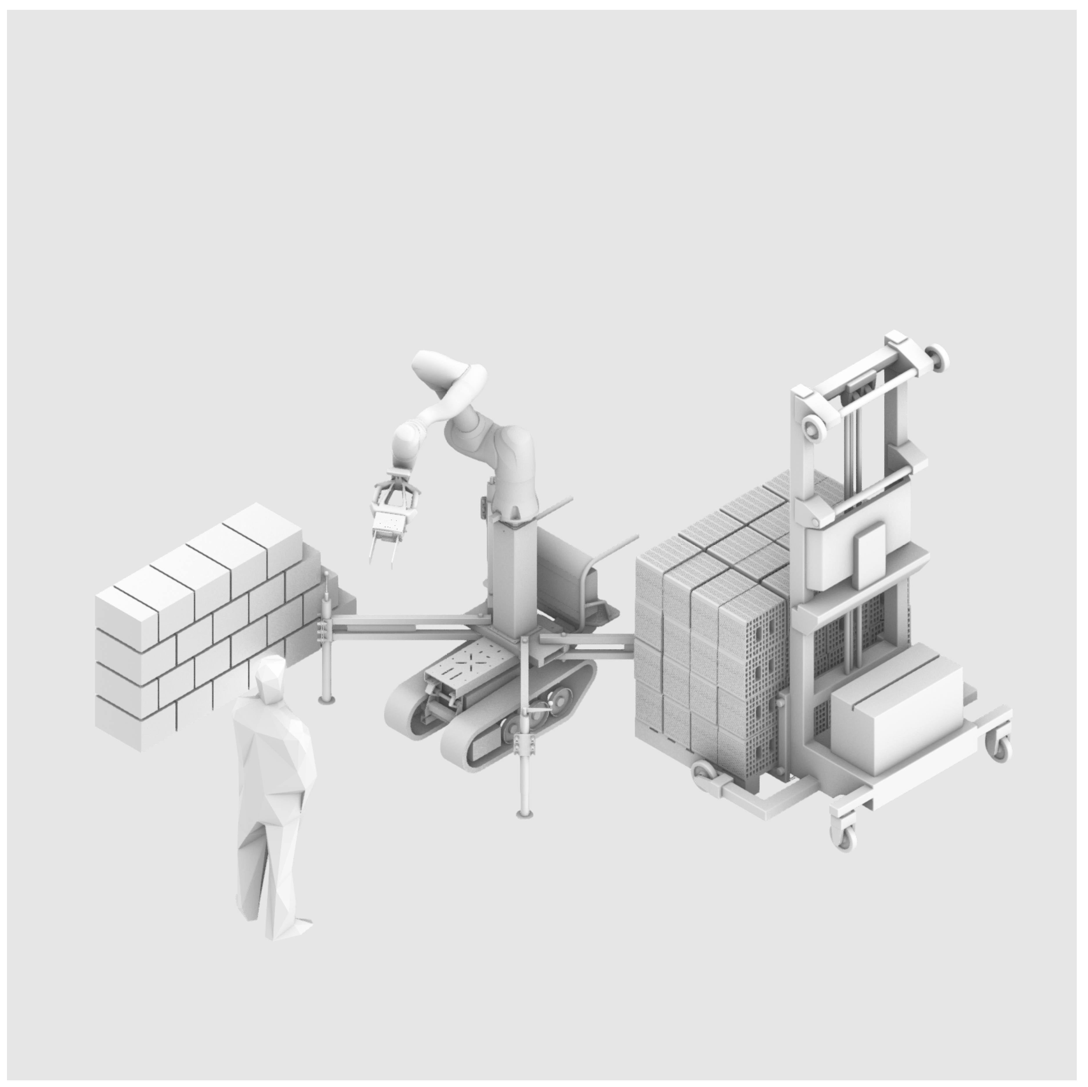
The experience of BRIX shifted the focus of the Bric-a-Brick from automating clay block wall construction towards relieving the major part of the manual work strains from the regular bricklayer profession, while still ensuring human-machine collaboration. In this way, the project promotes broader inclusivity to operators of different ages, genders, and abilities, nudging present practices towards an inclusive approach to make construction work more equitable and accessible, and emphasize the importance of creating technological solutions that respect diversity and value individual capabilities (Figure 20).
Therefore, to meet TRL 9 by December 31, 2026, some key assumptions have been established to enable a more immediate dive into the core characteristics of the machine.
The first set of assumptions is about the replicability of the job type: in this case-scenario doors and passages can be as narrow as 800 mm, attention is focused on clay block construction for walls (also load-bearing walls) of around 3 meters of height - since modular yet cost-effective solutions for a small-scale residential buildings in Italy normally employ clay block construction -, and a typical residential structure withstands live loads up to 2 kN / m2 [20]. It is mandatory to work with this limits (Figure 9), as with another important factor: foundations are already put in place.
These requirements are met if the prototyped system is: compact - its width is small enough to allow the machine to easily pass through doors (Figure 10) -, if it is lightweight - easily transportable on site employing a simple van (Figure 8) and movable next to the wall directly by the bricklayer - therefore cutting the majority of the system’s transportation costs, and if it comprises a lifting mechanism for the robot arm to lift the clay block at the required height to finish the wall construction.
The second set of assumptions is about the features of the clay block to be used, and precisely why the same model - Wienerberger Pth BIO MOD 30-25/19 - of the BRIX prototype was employed in this case.
Since in this phase it is essential to adopt an innovative approach to problem-solving, prioritizing the elimination of non-essential elements that, while potentially elegant, do not necessarily contribute to long-term objectives, a Porotherm clay block with rectangular apertures at the center was assumed to be the easiest to use straight away. The fingers of a standard industrial gripper can in fact immediately conform to its surface without requiring additional shape customization for adaptability. It was deemed unessential to focus on gripping flexibility in this phase, opening up to other shapes of clay block with a custom-designed mechanical gripper when, in prospect, a vacuum-based gripper adhering to the lateral surface could grant much more resilience for a plethora of other types of shapes.
Figure 8.
Bric-a-Brick can be transported on site employing a van.
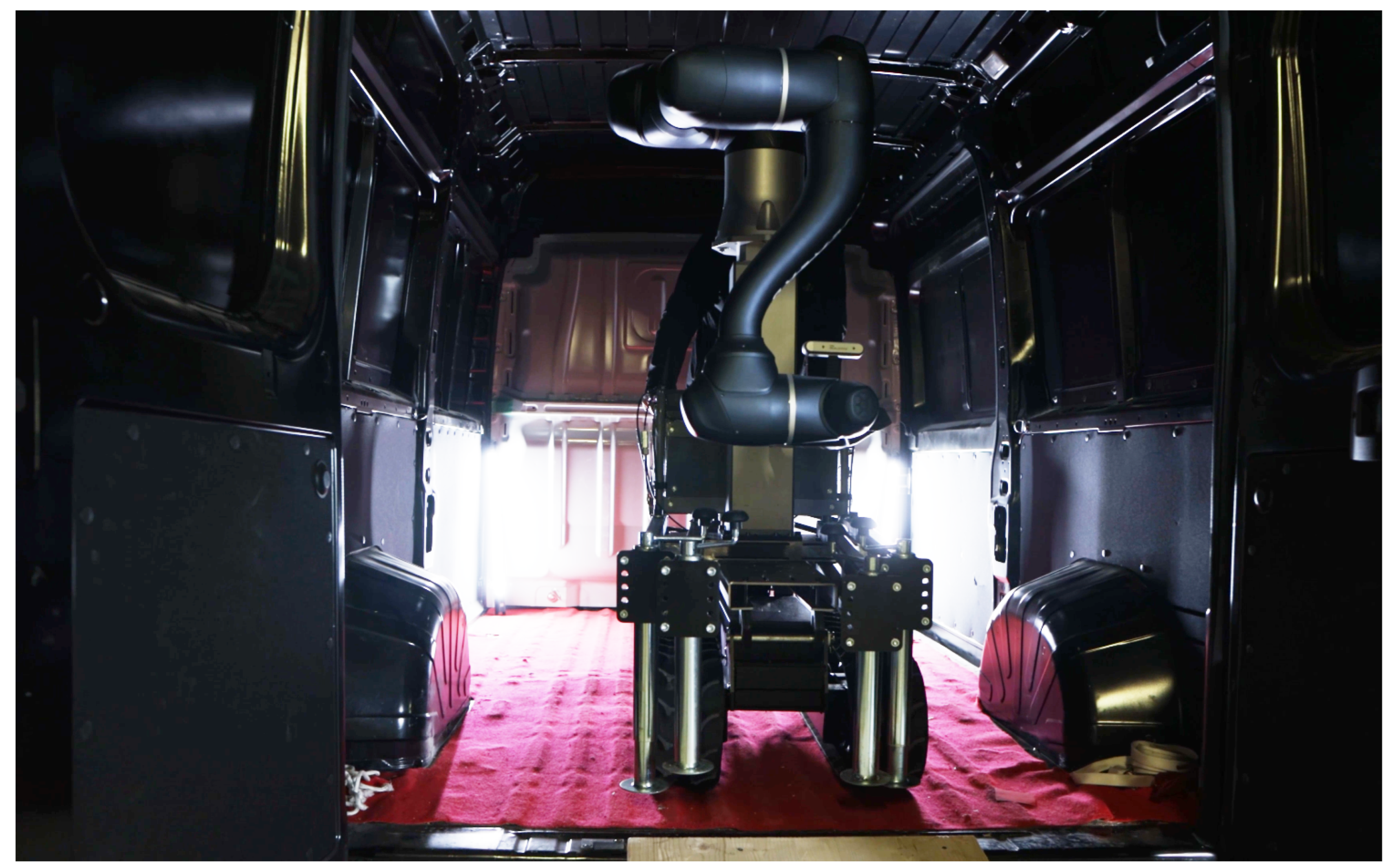
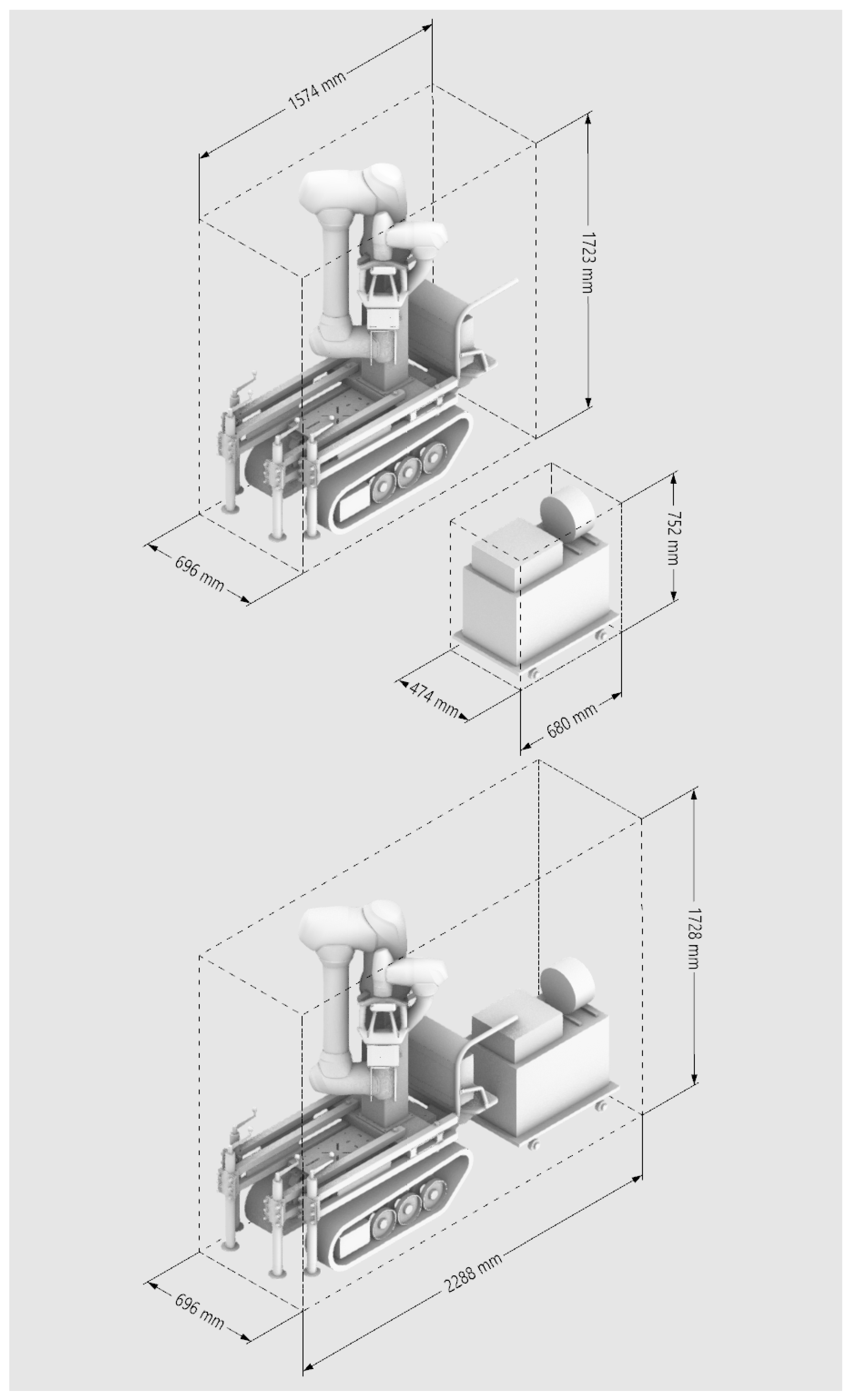
Figure 9.
The bounding box of the control box and of Bric-a-Brick in pack position.
This method has direct drawbacks because, gripping the clay block from the top, Bric-a-Brick won’t be able to place the last row of the wall elements if it needs to place it directly under an existing beam. Nonetheless, as described above, since many criticalities of lateral mechanical gripping remain and the prototyping cost and effort is largely unjustified compared to its long-term prospects, it has been decided to adopt the most simple and cheap solution available and to deep-dive into other critical issues.
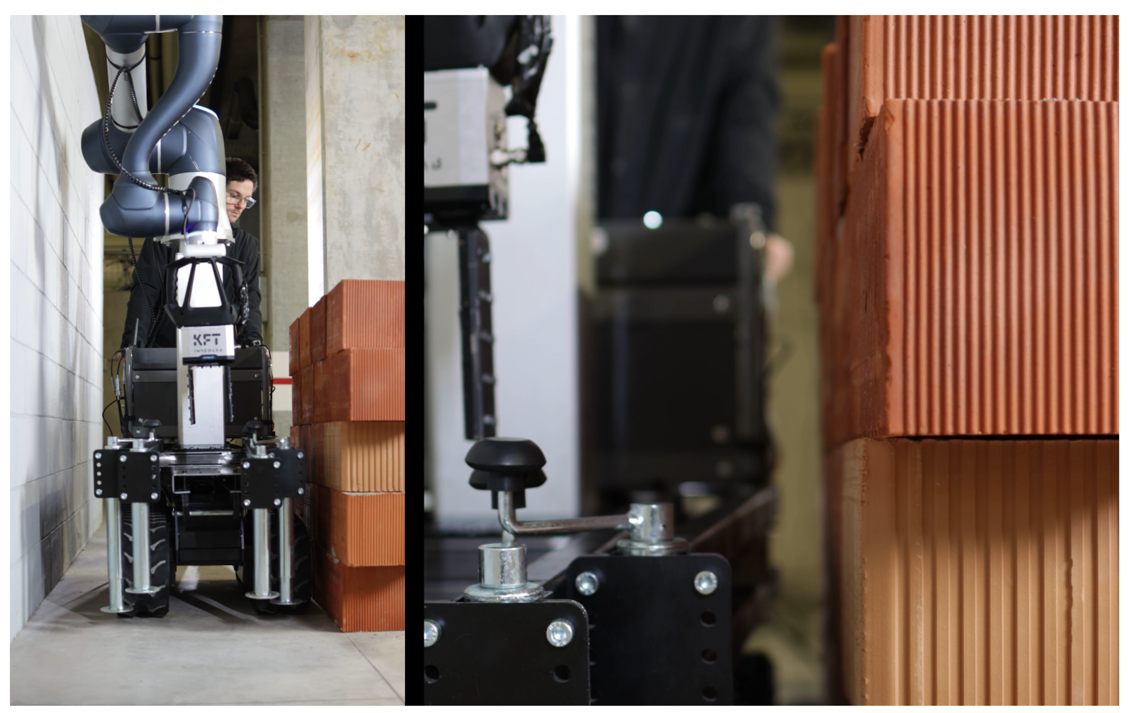
Figure 10.
Photo of Bric-a-Brick passing through a 800 mm passage. The wheelbarrow and the retracted stabilizing system account for around 600 mm of the total width, while the robot in pack position adds another 100 mm.
Figure 10.
Photo of Bric-a-Brick passing through a 800 mm passage. The wheelbarrow and the retracted stabilizing system account for around 600 mm of the total width, while the robot in pack position adds another 100 mm.
The perks of working with Porotherm blocks, among a great variety of block-based construction, is certainly their future sustainability prospects but also their shape’s high recognizability. In fact, if the geometry of the piece, its peculiar pattern of holes or silhouette, is simple enough to recognize and extrapolate from the surrounding environment, a computer vision system can detect objects in space with "seen" objects - i.e. supplying the CAD model (3D mesh) up front - without the need of real-time shape acquisition and reconstruction. The hardware setup can therefore be cheaper in this phase, mainly in terms of GPU used, and the focus can be placed on optimizing the pipeline on the software side.
Using a collaborative robot (cobot) with a high payload capacity of 25 kg is a strategic decision for the future development of Bric-a-Brick . This choice ensures that if the type, shape, or weight of the clay block evolves (i.e. if their prospect is to incorporate more and more insulating and finishing layers of the wall to augment its thermal transmittance) the cobot will be capable of lifting almost up to twice the current weight of the clay block .
Working with these premises, the solution could be effectively implemented within approximately one year of research an development, paving the way for future advancements and extensive testing of the Bric-a-Brick prototype. Despite its compact design, and the fact that it weights just 150 kg, the Bric-a-Brick delivers impressive range through its telescopic and retractable features (Figure 11).
3. Materials: Hardware and Software Overview
At the heart of the Bric-a-Brick lies the integration of a mobile base and a robotic arm through a lifting column and a manually operated stabilizing system (Figure 13). Following a strategic evaluation, at this stage of development, it has been decided to use mature, off-the-shelf technologies currently available on the market. Since the focus is not on optimizing for efficiency but on delivering a first working version, rather than reinventing core hardware components, it has been decided the complexity of interoperability and integration would be delegated to the software layer. This approach enables a quick unblocking of critical issues to move forward with development and concentrates efforts on the "missing parts".
A lightweight and cost-effective mobile base, increasingly used for transporting materials like sand, gravel, cement, and bricks across construction sites, is the wheelbarrow. As it helps reduce physical strain, speed up work processes, and improve safety by reducing the likelihood of worker fatigue or injury, it is a very versatile tool to overcome difficult terrains as well as steep slopes. Employing the typical construction site three-layer laminated spruce panel for formwork reinforcement (which are normally measuring 27 mm x 500 mm x 3000 mm) it is possible to manually load and unload the Bric-a-Brick from a van without the need of a tail lift (Figure 12). Wheelbarrows are not only simple to maneuver and very useful to solve logistical issues, they are also very cost-effective and compact compared to small cranes or other semi-movable vehicles like skid steer loaders, mini dumpers, or even forklifts.
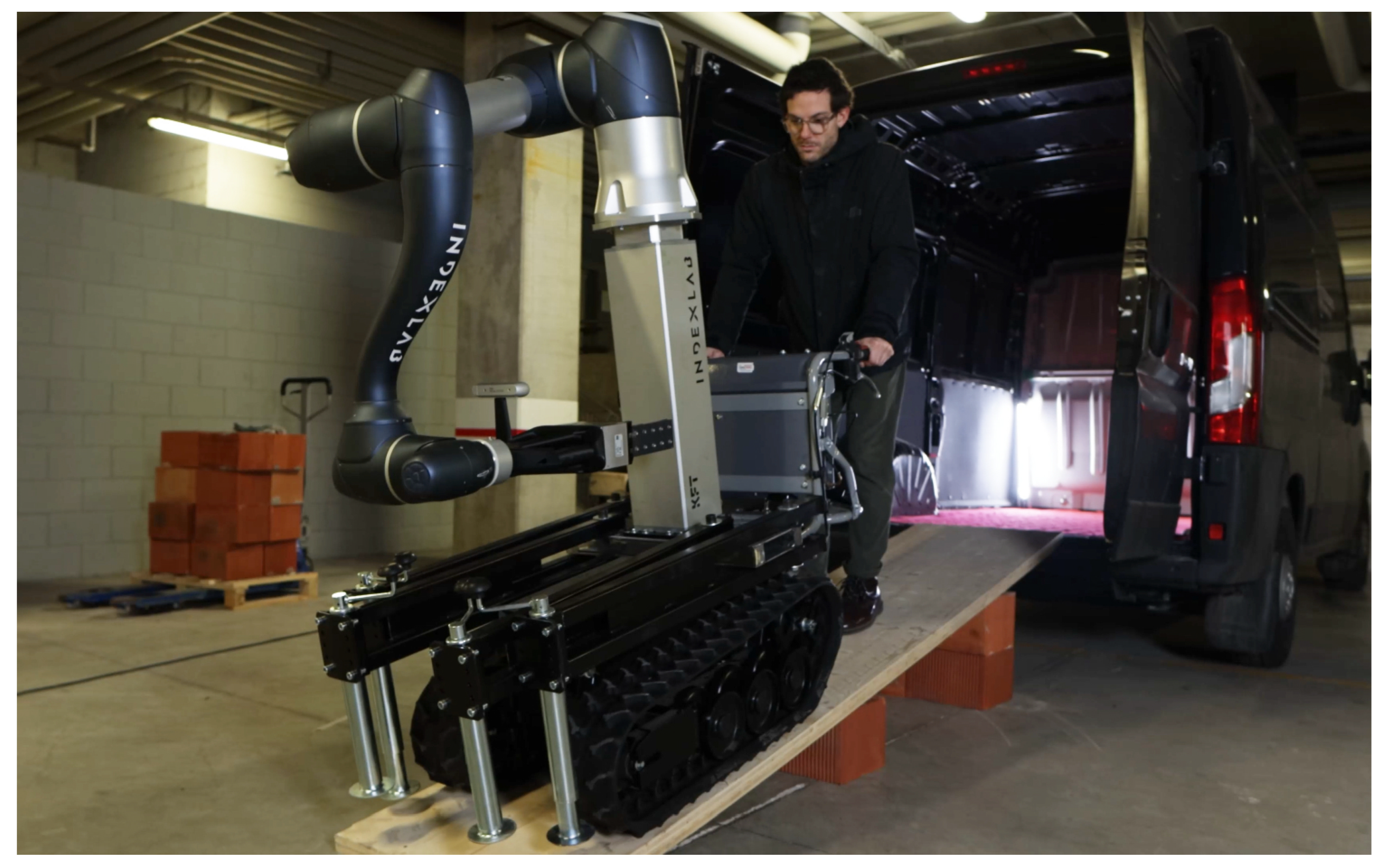
Figure 12.
Unloading the Bric-a-Brick is a simple and straightforward process involving just one person. Using a normal construction site three-layer laminated spruce panel for formwork reinforcement, an operator creates a slope to unload it from the van and manually guides it to the location on site.
The BEACH 270-E [21] is a tracked electric wheelbarrow with a load capacity of up to 450 kg designed to offer high-performance load transport on sloped surfaces up to 35%. This makes it especially suitable for use in construction, agriculture, and other labor-intensive sectors where transporting heavy items is routine and rough, uneven, grounds usually require machines with tracks. Equipped with an 800 W motor and powered by rechargeable 60 V - 20 Ah batteries, the BEACH 270-E can reach speeds of up to 5 km/h, ensuring emission-free operations and great adaptability.
Its removable loading bed, measuring 1320 x 1000 x 480 mm, was pulled out to install a custom bended steel 5 mm sheet interface, serving as connection between the wheelbarrow and the robotic arm. This metal piece’s geometry integrates a stabilizing system made of retractable square-section bars, with manual jacks at the end to balance the wheelbarrow, and a lifting column with a cobot on top. Provision was made for additional clearance at the front of the unit to accommodate the future integration of a supplementary robotic arm and, in the meantime, to allow for easy attachment and transport of objects."
The Bosch GCL 2-15 Professional Combi Laser [22] offers straightforward visual help to the operator to stabilize the machine. Featuring two centered plumb points, has a working range of 15 meters and laser class 2. Additionally, the included laser target plate enhances accuracy in various lighting conditions.
In order to lift the robot - and reach up to 4.5 meters with the fully extended arm - the Linak LC3E0008DK Elevate Easy [23,24] has been mounted on top of the metal piece: a robust lifting column weighting just 29 kg and measuring 163 mm x 163 mm x 730 mm when fully retracted. Designed with a three-stage telescopic mechanism, it is engineered for vertical actuation in collaborative robotic and industrial automation settings, enabling a long stroke of 900 mm with a payload capacity of up to 1000 N. It is powered by a 24 V DC supply and incorporates a brushless motor, which ensures high efficiency, low maintenance, and quiet operation. Depending on the spindle pitch, the unit can achieve a maximum speed of up to 100 mm/s, making it responsive enough for dynamic positioning tasks. The connection cables provide the necessary infrastructure for TCP master-slave functionality, ensuring communication with the robot controller.
Figure 13.
Overview of Bric-a-Brick ’s components
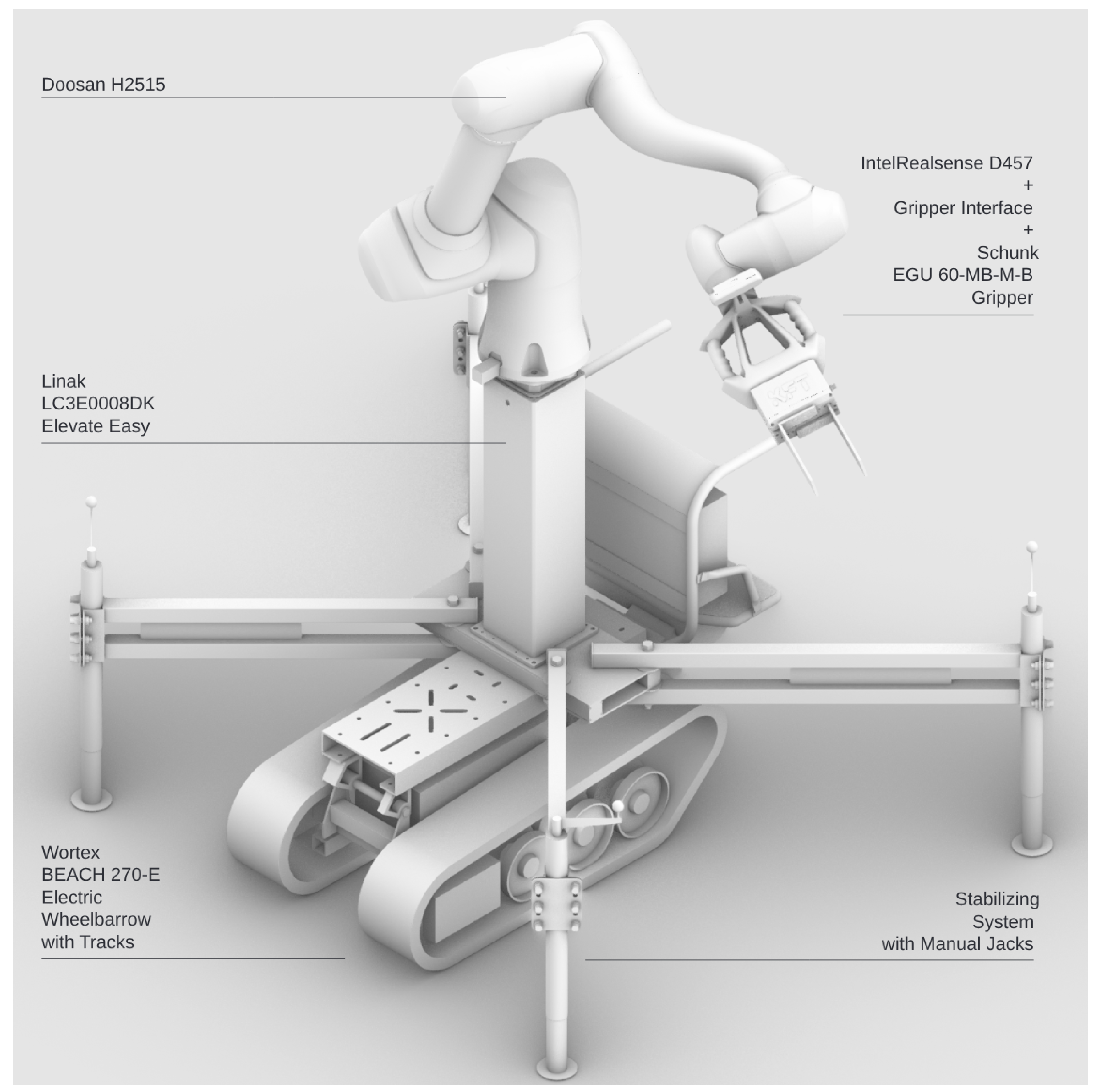
Bric-a-Brick operations are carried out with a collaborative robotic arm (Doosan model H2515 [25]) mounted at the center top to ensure optimal balance and reach.
It is always useful to point out that choosing a cobot over an industrial robot goes beyond payload and weight advantages. While benefits like reduced energy demand and integration flexibility support easy prototyping, cobots are part of a broader strategy to blend robotic productivity with human flexibility in safe collaboration zones. Cobots feature advanced safety sensors and built-in limits to ensure secure operations. Their intuitive interfaces and low-code setups, combined with computer vision, dramatically reduce deployment time, especially in dynamic, unstructured environments.
The H2515 is part of the H-SERIES and is a collaborative 6 d-o-f robot with a payload capacity of 25 kg and an operating radius of 1500 mm. It features 6 torque sensors and operates efficiently with low electrical power consumption. The maximum linear TCP speed is 1 m/s, and it has a repeatability of ± 0.1 mm.
Although more affordable robotic arm options, with higher reach but lower payload, were considered for the application, the decision was made to prioritize the collaborative robot with the highest payload available on the market. This choice ensures that, even with an extended arm reach - and with a heavier clay block compared to the chosen one for the demonstration - the robotic system maintains optimal joint load distribution, preventing excessive strain on the actuators and ensuring stable movements without compromising mechanical integrity.
The system’s control box, comprising an inverter to convert the battery voltage of 48V DC into alternating current at 220V AC and 50 Hz, the Doosan controller, its Teach Pendant, and a notebook host machine, is housed on top of a trailer measuring 680 x 540 x 320 mm. This trailer is designed for easy detachment and transportation on-site. This configuration is particularly critical for the future integration of the wheelbarrow’s battery pack as a power source, an objective that has not yet been tested but will be the next step in the integration process.
As gripper, Schunk’s EGU 60-MB-M-B [26] was chosen to provide a universal electric gripper designed for handling weighting less than 5 kg. It features a 60 mm stroke per jaw, with gripping forces ranging from 325 N to 1300 N, and these characteristics were selected as being the most suitable to mechanically grasp the clay block , inserting the fingers inside its central holes and considering a weight range of the piece from 10 to 18 kg. Powered at 24 V, it ensures secure hold via grip force maintenance. Operating temperatures range from 5 to 55°C in ambient temperature, which is normally fine in temperate environments, and particularly in the context of construction sites where the horizontal partitions are already in place and the exposition to harsh outside climate conditions is not common. The gripper interfaces with the notebook controller via a Modbus RTU to USB interface.
As the primary computer vision module for depth perception and object detection, Bric-a-Brick mounts an Intel RealSense D457 [27], a stereo depth camera with global shutter sensors, offering depth sensing from ~0.52 to 6 meters with <2% error at 4 meters. This range is optimal for the application, considering error-prone depth sensing and disparities begin to appear at almost double the span of the robot working range. It delivers depth at up to 1280 × 720 pixels at 90 fps and RGB at 1280 × 800 pixels at 30 fps. The depth field-of-view is 87° × 58°, which is optimized for mid- to long-range perception. IP65-rated, it is suited for dusty industrial environments like the average construction site and can withstand projected water.
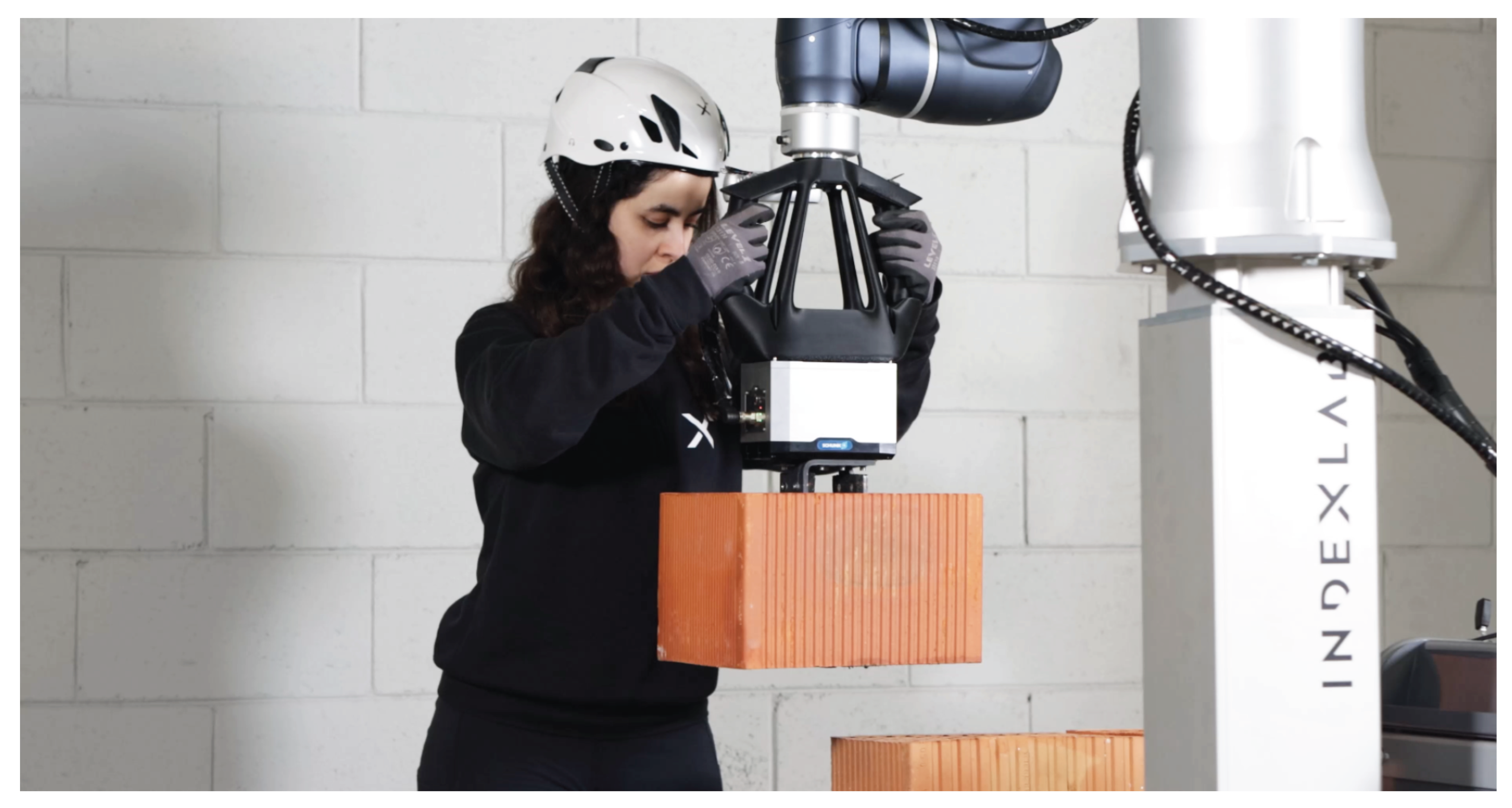
A custom 3D-printed robot flange-gripper interface (Figure 14) has been designed and engineered in order to add handles to the end-effector and easily manipulate the robot arm, to position and secure the camera in an optimal orientation for image capture, and to comprise four buttons for both taking direct control of the Doosan robot while running the program, and releasing the clay block in the desired position. Overall, the interface serves as backup if the camera is not being able to recognize the clay block because of poor lighting conditions, but it also prospectively provides a comfortable remote control for enhanced data acquisition of the cobot motion and its joint sensors.
The ergonomics of this piece, printed in PLA using a Bambu Lab X1C 3D Printer [28], allows for easy grasping by the operator and has embedded safety, giving an informed consent to release the clay block only when both buttons are pushed and inside of the collaborative volume . The weight compensation of the cobot gives more overall maneuverability to the bricklayer in the careful deployment of the gripped clay block using the handles.
The hardware for the Bric-a-Brick application is integrated using a Dell Inspiron 7577 [29] as host machine. This computer has 16.0 gigabytes of RAM memory and features an Intel Core i7-7700HQ processor with eight cores and a dedicated NVIDIA GeForce GTX 1060 [30] graphics card.
Serving as base for the major part of the pipeline is an infrastructure of Docker microservices running Ubuntu 24.04.1 LTS, 64-bit, with a firmware version of 1.17.0, with a kernel version of Linux 6.8.041-generic. The streaming pipeline, image segmentation, object recognition, and retrieval of the clay block gripping plane coordinates use a combination of Python scripts to output a coordinate file. The use of Docker containers for these Python scripts ensures that each service is isolated, making the infrastructure more scalable, maintainable, and portable for future use-cases.
The Segment Anything Model (SAM 2) [31] is a state-of-the-art segmentation tool designed to identify and delineate objects within images. It operates by leveraging advanced deep learning techniques, specifically trained on a diverse dataset to enhance its generalization capabilities. SAM 2 employs a text prompt or point detection approach, allowing users to specify regions of interest (ROIs), which the model then processes to generate segmentation masks. This flexibility enables it to adapt to various applications, from medical imaging to autonomous driving. The model utilizes a combination of convolutional neural networks and attention mechanisms to accurately capture object boundaries and details. By analyzing pixel-level information, SAM 2 can distinguish between overlapping objects and complex backgrounds.
To retrieve the 6 d-o-f pose NVlabs’s FoundationPose [32,33] pipeline has been used. FoundationPose is a unified model for object pose estimation and tracking that supports both model-based and model-free approaches. It can be applied to new objects at test-time without fine-tuning, requiring only a CAD model or a few reference images. The model uses a neural implicit representation for novel view synthesis, ensuring consistent pose estimation across different setups. It achieves strong generalization through large-scale synthetic training, a novel transformer-based architecture, and contrastive learning [34].
Supplying a CAD model of the clay block and its SAM 2 segmented mask on the RGB image taken from the camera, FoundationPose recognizes the pose of the clay block and supplies the 6 d-o-f coordinates of the plane of the mesh in the space of the frame (Figure 15).
On Windows 10, this coordinate file is imported in a simulation environment in Grasshopper3D [35], a popular visual programming environment for 3D modeling and analysis built on Rhinoceros. This Grasshopper3D script interprets the coordinate file, simulates the motion of the robot using the visose/Robots library [36], and plans the optimal path for the robot arm to grip the clay block , move it to the collaborative volume safely, interact with the bricklayer , and go back to pick another clay block .
4. Methods: Implementation
The tests for the Bric-a-Brick project were undertaken at the INDEXLAB laboratory in Lecco, Italy, and specifically, in a covered outdoor space (Figure 16) adjacent to the parking area, where the lighting is uniformly distributed at a low intensity, creating consistent yet subdued illumination throughout. This lighting configuration, which prioritize energy efficiency while avoiding any harsh contrasts or shadows, should be the minimum standard to test the camera vision system. While no direct light sources were aimed at or near the testing area, in the context of the construction site direct sources of light can be added at convenience to ensure the clay block gets recognized in most conditions.
At first, employing two standard three-layer laminated spruce panels commonly used for formwork reinforcement in construction, placed one on top of the other, a proof of concept of loading and un-loading the Bric-a-Brick from the van was successfully performed. With the panel serving as slope for the wheelbarrow, without the assistance of a tail lift (Figure 12), a single operator could handle these tasks intuitively and without supervision.
In a second phase, the operator guides the electrical wheelbarrow in the adjacencies (within the 1500 mm cobot arm reach, and usually at 1200-1300 mm distance) of the clay block pallet and of the wall to be built, manually extends the stabilizing system made with simple retractable square-section bars and adjusts the jacks at the end. In order to ensure the wheelbarrow is level, the operator uses the combi laser. Finished this quick setup, the operator starts the program on the notebook machine (Figure 16).
The operator knows where to manually guide the wheelbarrow from a 3D visualization on the notebook screen indicating how the clay block wall is clustered (Figure 17) and in what area - approximately - should the robot and the pallet be placed to pick-and-place every clay block cluster correctly. In these visualization, the bricklayer can orbit with the mouse and point-and-click to see annotations of distances and measures.
This visualization is prepared before by another operator - designing and planning the construction of the wall according to the chosen clay block - via a Grasshopper3D script that suggests its building process according to defined clustering rules and the setting of some parameters. If each wall has a certain axis, width and height, it can get divided based on the clay block following a convenient thickness of the mortar joint. Then, subsequently, it gets split into "macro-rows" which have the width of the wall and generally are about 1/3rd and 1/4th of the height, based on the specific dimensions of the wall and the robot reachability. These macro-rows are then divided as well, using clusters of a certain number of blocks - generally between 8 and 11 - that constitute the batch of blocks which Bric-a-Brick will build at a time. After having pick-and-placed this batch, the wheelbarrow will be moved and the routine continues to the next batch of blocks. The parameters that control this process are mortar thickness, dimensions of the clay block , batch geometry. The output is a simulation of robot reachability, a number and visualization of blocks in each batch, the quantity of batches inside a macro-row of blocks.
It is interesting to note here that the very nature of traditional clay block wall construction - the process via which the bricklayer places the blocks to build the first row, and on top of that the second row, then the third... until the bottom of the structural beam or ceiling - is in the case of Bric-a-Brick completely different. It would be irrational to move the wheelbarrow multiple times to build the wall per single rows, as it would mean the stabilizing system is repositioned and readjusted many times, leading to losses in productivity and possibly more calibration errors. If the wall is built in macro-rows, the batches of blocks could all have the same parallelogram shape (a part from the batches at the ends, which have a triangular-like, peacock-tail, shape to conform to the constraint of vertical structure) allowing for faster construction (Figure 18).
When the Grasshopper3D script supplies the visualization on the Rhinoceros canvas of the wall divided in portions - in convenient clay block batches according to the reachability of the cobot, the bricklayer is prompted to give consent to begin with the next phase.
The cobot begins a scanning routine using the camera, which consists of waiting for manual input by the user to hand guide, using the handles, the end-effector to point at the pallet of bricks, registering the position, and then moving in spiral mode (a built-in function in the Doosan movement library) outwards and inwards while saving RGB and depth frames with the camera using the best streaming configuration available. Specifically, an openCV [37] window is opened on the notebook and the operator sees the live camera stream framed by the current end-effector pose. When the clay block pallet is approximately in the center of the scene, the operator presses a key to go to the next stage, or another to redo this step.
If the frame is satisfactory, the stream begins and, with the pallet well visible, the operator is prompted to sketch - on the screen using the mouse - something to define the ROI of the pallet from the background of the construction site. Other modes are available to segment the pallet of bricks, such as text mode and point mode, but they were not extensively tested since it was deemed more intuitive to draw with the mouse directly on the picture instead of relying on a point-and-click solution.
Figure 18.
In the first phases of the construction process, the first clay block macro-row is being built with the clay block pallet on the ground and the lifting column retracted.
Figure 18.
In the first phases of the construction process, the first clay block macro-row is being built with the clay block pallet on the ground and the lifting column retracted.
A bounding box is thus derived from the rectangle convex hull of the sketch, and the SAM 2 model starts to segment the bricks, refining in real-time the segmentation while the stream is running and the script is saving frames in the dataset folder on the host machine. Even if the segmentation is not always correct and further refining could still be needed (i.e. the contouring of the clay block is pixelated, some portions are missing, some of the bricks are not part of the segmented fragment because the lighting conditions are poor) the scope of this part is only to remove a portion of the overall frame and separate it from the background. This part ensures computing power is not dispersed running the algorithm on the background of the image.
An automatic offset of roughly 30 pixels applied to the ROI ensures the majority of the blocks are comprised within the scene, a second bounding box is derived, and the RGB and depth frames are cropped and saved in another folder.
The program waits and prompts the user to supply a CAD model to identify within the ROI. In this case, the 3D mesh of the clay block was made readily available - alongside a plethora of other clay block mesh options - through a Grasshopper3D script. This script takes in Porotherm datasheets in .PDF as input, converts the plan of the clay block to vector, extrudes it, caps it, textures it with a solid orange colour, exports it in .STL format. When the user selects the appropriate mesh from the clay block list, the subsequent part of the script begins.
In this last part of the pipeline, FoundationPose compares the segmented portions of the scene and reconstructs - from the cropped RGB and depth frames of the scene - the 6 d-o-f pose of the recognized blocks. Another openCV window opens up and shows the video result of the operation, overlaying a bounding box of the supplied mesh and the x,y,z axis of the plane to the items it recognizes on the image stream. It then closes and outputs the coordinates files of the plane for each detected clay block in every frame of the RGB cropped stream.
A Python function calculates, among these planes representing the coordinates of each recognized clay block , what are the ones on the top of the pallet, dividing the top row from the other ones. Then, subsequently excludes the outliers from these coordinate values - i. e. the ones describing plane coordinates which are not comprised within the convex hull of the majority of the other planes, or the ones that feature a completely different orientation - and outputs one single file with one univocal gripping plane coordinate for each detected brick.
A Grasshopper3D script automatically opens up, interpreting the coordinates and plotting them in the simulation of the corresponding environment in the robot world. Each clay block is rendered orientated as the coordinates of the plane in the Grasshopper3D canvas, and the top row is the first one to be de-palletized, starting from the pieces nearer to the robot. It then calculates the movements to pick-and-place all blocks needed to construct the first portion of the wall with the first calculated clay block batch, generally using the top row of the pallet and a part of the blocks of the row underneath.
The Grasshopper3D script outputs a program, employing a custom post-processor, orchestrating linear motions at 50 mm/s to move the clay block outside of the pallet area and bring it inside the collaborative volume for the operator to take control of the end-effector in joint motion. After having placed the mortar on the clay block , the operator is prompted to take control of the cobot via manual hand-guiding by pressing the two buttons on the handle of the 3D printed gripper interface.
The operator places it in the desired position, applying the required pressure on the mortar bed to make it fully adhere, then presses the two buttons on the top of the gripper interface to successfully de-grip the clay block , and presses once more the two buttons on the handles to go outside of manual hand-guiding mode. The cobot registers the clay block ’s placement coordinates and goes back, at 50 mm/s, in linear motion up in Z, then to the collaborative volume again before going to grip the successive clay block from the pallet. This operation is carried out until the first portion of the wall is completed, then another cycle begins and the wheelbarrow must be re-placed according to the initial 3D simulation.
When the last macro-rows have reached a certain height, a lifting mechanism for the bricklayer is required as well, to continue collaborating with the robot comfortably at a certain height (Figure 19) and finish the wall.
5. Results
Overall, 12 full de-palletizing cycles have been tested for the Bric-a-Brick project (Table 1). The loading and un-loading operation performed by a single operator were completed respectively in 560 and 670 seconds for each operation, demonstrating the ease of use and the efficiency of the system. The tasks of robot packing for transport and un-packing contributed for roughly 150 seconds downtime to the loading and un-loading operations.
When the electrical wheelbarrow has been un-loaded and guided in the adjacency of the clay block pallet and of the wall to be built, the operator extends the stabilizing system and adjusts the jacks at the end using the combi laser. The operator took from 400 to 500 seconds on average to complete these tasks. Nevertheless, during the first four tests the full de-palletizing cycle had to be aborted, and the operation of extending the stabilizing bars had to be repeated with another configuration, because it did not prove to be stable enough when two bars on one side were "too parallel" to the wheelbarrow’s length.
When the scanning routine began, from the hand guiding part to the end of the spiral mode movement, no more then 200 seconds were employed during all tests, with lows of 140 seconds. Five times the operation had to be performed again - i.e. with the clay block pallet approximately in the center of the scene - to make sure that the spiral mode motion would catch the majority of the first row of blocks in one single operation.
The sketching stage failed the first two times, then the operator understood how to define the ROI in the most straightforward way: drawing a simple sketched circle. This part took commonly no more than 11 seconds.
When the user selects the appropriate mesh from the clay block list, FoundationPose begins the recognition routine. While this part, in an industrial application, would be trained in order to recognize the specific clay block , it already worked pre-trained out-of-the box for 9 of the 12 tests that were conducted by our team. On the notebook used, based on the frame-rate of the stream, this operation took from around 250 seconds (for a 480 x 360 pixels resolution and 30 fps frame-rate) to a maximum of 520 seconds (when streaming at 640 x 480 pixels resolution and 30 fps frame-rate). Higher resolutions were tested outside the Bric-a-Brick ’s testing pipeline but they proved to be taking substantially longer - for the recognition of more than one brick - considering the current hardware setup.
When the coordinates have successfully been selected, the outliers excluded and the sifted coordinates exported, the Grasshopper3D simulation opens up and renders the scene and the robot trajectories. In the these tests, this part took on average from 39 to 100 seconds based on Grasshopper3D opening time via the Python subprocess library. The trajectories are then visualized and the program is generated. The operator is prompted to send the program to the robot and the motions begin.
The linear motions - to move the clay block outside of the pallet area and bring it inside the collaborative volume - were performed correctly 7 times without any interruption, 3 times with interruptions (with the cobot blocking the motion when extracting the clay block too abruptly from the top batch and prompting the user to unblock the joints again and resume the motion) and 2 times causing another, adjacent clay block to fall down. These results are promising but show the difficulties in extracting an element too squeezed between other clay elements in the pallet. The timings, at 50 mm/s motion, are between 15 to 40 seconds to undergo these tasks.
It is useful to note that these errors usually occur because of the non-structured fashion by which these blocks - depending on the producer - are placed on the pallet. When the wrapping paper around the pallet of bricks is ripped apart, multiple things can occur. General misalignment, the presence of broken pieces in correspondence to the central holes of the clay block , inconsistencies in the positioning of the clay block rows in one pallet with respect to another pallet provided by the same producer, and other issues that generally the bricklayer has to deal with using dexterity, are in the case of Bric-a-Brick still dealt with the same way: using human "help" to facilitate automation. That is why, in any moment within the execution of the script, there is idling function which waits to be called by a double tap on the Doosan arm cockpit to abort the pipeline, take manual control via the handles again and use the system as a traditional lifter, counterbalancing the clay block ’s self-weight.
When the operator takes control of the end-effector in joint motion, the mortar has successfully been placed (the bricklayer takes about 8 to 10 seconds in doing so) and the hand-guiding fo the clay block begins, by pressing the two buttons on the handle of the 3D printed gripper interface. Generally, depending on the placing position of the clay block , the operation takes from 15 to 30 seconds, then the cobot registers the clay block ’s placement coordinates and goes back in linear motion up in Z, then to the collaborative volume in about 35 to 45 seconds.
None of the 12 tests conducted has put in place a full pick-and-place cycle of the clay block using the lifting column. While all the programmed "automatic" cobot movements employing the lifting column were tested, no interaction test with the bricklayer in height has been done at this stage. Further advancements of the Bric-a-Brick prototype will ensure these tests undergo in a real-world construction site with all the safety requirements and standards in place.
6. Discussion
Overall, the timings for the performed operations were deemed satisfying for a prototype comparing with the traditional wall building method.
Construction with Porotherm block achieves 25-30 m2 per person per day, compared to the 12-15 m2 typical of traditional methods [19]. Using a median of 20 m2 (a 4 x 5 meters wall) for a regular bricklayer 8 hours day shift as a benchmark and using the chosen Porotherm clay block , it has been calculated that the wall is composed of roughly 230 blocks, resulting in an overall productivity of 28,75 blocks per hour.
Summing up all the partial timings of the carried out operations, Bric-a-Brick takes from 1029 to 1334 seconds on average to complete the pick-and-place per clay block batch. Let us consider that, for a 4 x 5 m wall of roughly 230 blocks, around 23 batches of pick-and-place operations will be carried out. If 2/3rds of them will employ the lifting column to be brought at a certain height, the time increase for these batches should be calculated and an additional 20 seconds per batch (10 for the column to extend and bring the cobot up and 10 for it to get back down) is to be accounted for.
Symbolically, adding 20 seconds to the last 8 tests could take into account the use of the column while - on average - the cycle timings were getting shorter reflecting the bricklayer ’s learning curve and improved operational efficiency over time.
The median of the first 4 batches (1310 seconds) is multiplied for the first 7 batches of the wall (corresponding to the first macro-row, the one on the ground), and the median of the last 8 batches (1106 seconds) is multiplied for the last 16 batches (corresponding to the macro-rows on top of the first one). This yields 9170 seconds (around 153 minutes) to complete the first macro-row and 17696 seconds (around 295 minutes) to complete the other ones. To these, the loading and unloading times of the robot are still to be added: around 9 and 11 minutes respectively. This rough estimate gives a total of 468 minutes, or 7.8 hours to complete the wall.
While these tests are not to be taken as a real-world implementation metrics, they show promising results. Since the cycles were performed constructing the same clay block batch over and over, their timings inevitably lack generalization for a real-case scenario of building a 20 m2 wall in a construction site.
While in terms of efficiency, at this stage of development, Bric-a-Brick ’s collaboration strategy does not drastically reduce the overall cycle-time of building the clay block wall, it surely reduces physical strain and provides some seeds of replicability and automation for the case-scenario. Even if it were to substantially maintain the productivity level proper of skilled labor, Bric-a-Brick could greatly relieve the bricklayer from heavy physical loads and open up the profession to more machine-human collaboration (Figure 20) without renouncing safety and the overall quality of construction work.
The project has the potential to inspire applications in other sectors as well, such as logistics and manufacturing, where the challenges related to ergonomics and efficiency are also critical. Future research will explore several additional topics, and the team is actively seeking investors to support ongoing development and advance to the next phases of the project.
The current mechanical gripper should be replaced with a vacuum-based gripping system to improve adaptability, reduce mechanical complexity, and enhance reliability in handling various brick geometries. The space in the front of Bric-a-Brick can accommodate a 10 bar compressor ensuring that, if electric vacuum-based gripping systems are not strong enough to pick up the clay block , a pneumatic one can easily be implemented.
The system’s mechanical stability can be significantly improved by incorporating a linear actuator-based stabilization mechanism instead of a fully manual one, reducing undesired movement or vibrations during precision tasks.
The manually operated electric wheelbarrow can be replaced by a custom-designed Autonomous Guided Vehicle (AGV), providing navigation (and also material transport and monitoring) within the construction site. While this step involves re-thinking of the vehicle from scratch, the integration of the existing wheelbarrow’s battery pack as a power source for all Bric-a-Brick ’s equipment can be faster and more straightforward to implement right away.
Figure 20.
Inclusivity lies at the heart of the Bric-a-Brick project, guiding both its design and implementation. Weight compensation, maneuverability and embedded safety are key to ensure that Bric-a-Brick promotes broader access to the profession, including operators of different ages, genders, and abilities by design.
SAM can be further optimized through user-defined segmentation cues, such as specifying inclusion/exclusion zones or reference points. Additionally, enhanced debugging tools and operator feedback mechanisms should be implemented to enable iterative segmentation corrections, such as point-and-click exclusion or inclusion areas.
The current notebook-based user interface may be replaced with either a native application on the Doosan Teach Pendant or a browser-based web application developed using Flask that runs on a tablet, improving usability and deployment flexibility.
The gripper currently interfaces with the notebook controller using a Modbus RTU protocol over a USB interface. A planned upgrade will transition this communication to Modbus TCP over Ethernet, enabling more robust, faster, and scalable integration with the broader automation network.
The process of mortar placement can be fully automated through the integration of a mortar dispensing system, synchronized with the bricklaying cycle, to ensure consistent and efficient material application.
There is significant potential for enhanced integration between digital building models (BIM) and physical construction, enabling a continuous BIM-to-built workflow with minimal manual intervention. The robot’s flange-gripper interface serves a dual role: executing tasks and acquiring data. While manipulating the brick, trajectory data can be captured and stored in a spatial database. This dataset can then be used to train a large language model (LLM) for autonomous trajectory generation. As the dataset grows and the AI model improves, more of the robotic process can be automated by comparing real-time wall construction with a parameterized BIM and generate future actions accordingly.
Using an augmented reality (AR) visor integrated with a Building Information Model (BIM), the system can project the robot’s planned operations into the operator’s field of view. This would enable real-time spatial awareness, allowing the operator to see from the robot’s perspective — similar to capabilities offered by the Brix system. A wearable sensor (e.g., RFID, UWB, or IMU-enabled device) can be employed to detect when the operator enters the brick loading zone, enabling the robot to adjust its behavior accordingly for improved safety and coordination.
Overall, the application architecture could evolve toward real-time operation by leveraging real-time operating systems (RTOS), time-synchronized fieldbus protocols (e.g., EtherCAT, TSN-based Ethernet), and low-latency edge computing. This would enable deterministic task execution, such as closed-loop motion control, real-time feedback from vision or force sensors, and dynamic trajectory adjustments based on environmental changes or operator input, significantly enhancing system responsiveness and reliability.
Funding
This research is auto financed by the authors and the companies involved. No-conflicts with third parties.
Data Availability Statement
The data presented in this study are available on request from the corresponding author.
Acknowledgments
The authors of this paper thank the company KFT Costruzioni srl that supported the research, and in particular Federico Trebini and Roberto Orrù. The authors thank their colleagues at INDEXLAB who contributed to the technical development and the testing phase of the system, and in particular Imane El Bakkali. A special thanks goes to Homberger spa, and in particular to Gianni Ossola and his team.
Conflicts of Interest
The authors declare no conflicts of interest.
Abbreviations
The following abbreviations are used in this manuscript:
| MSD | Musculoskeletal disorder |
| Cobot | Collaborative Robot |
| SAM 2 | Segment Anything Model 2 |
| ROI | Region of Interest |
References
- United Nations Environment Programme. 2023 Global Status Report for Buildings and Construction: Beyond foundations - Mainstreaming sustainable solutions to cut emissions from the buildings sector; United Nations Environment Programme, 2024. [CrossRef]
- 93digital. Future of Construction. Available online: https://www.oxfordeconomics.com/resource/future-of-construction/ (accessed on 2025-06-04).
- Agency, I.E. Global Status Report for Buildings and Construction 2019 – Analysis. Available online: https://www.iea.org/reports/global-status-report-for-buildings-and-construction-2019 (accessed on 2025-06-16).
- Brucker Juricic, B.; Galic, M.; Marenjak, S. Review of the Construction Labour Demand and Shortages in the EU. Buildings 2021, 11, 17. Number: 1 Publisher: Multidisciplinary Digital Publishing Institute. [CrossRef]
- ABB Robotics advances construction industry automation to enable safer and sustainable building. Available online: https://new.abb.com/news/detail/78359/abb-robotics-advances-construction-industry-automation-to-enable-safer-and-sustainable-building (accessed on 2025-06-04).
- MGI-Reinventing-construction-A-route-to-higher-productivity-Full-report. Available online: https://www.mckinsey.com/~/media/McKinsey/Industries/Capital%20Projects%20and%20Infrastructure/Our%20Insights/Reinventing%20construction%20through%20a%20productivity%20revolution/MGI-Reinventing-construction-A-route-to-higher-productivity-Full-report.pdf (accessed on 2025-06-06).
- How Automation is Shaping the Construction Industry. Available online: https://www.procore.com/en-gb/library/construction-automation (accessed on 2025-06-04).
- BauBot - fischer international. Available online: https://www.fischer-international.com/en/products/innovationen/baubot (accessed on 2025-06-05).
- USA, H. Jaibot Drilling Robot. Available online: https://www.hilti.com/content/hilti/W1/US/en/business/business/trends/jaibot.html (accessed on 2025-06-05).
- Doka. DokaXbot Lift - Doka. Available online: https://www.doka.com/en/system-groups/doka-floor-systems/panel-floor-formwork/dokaxdek/dokaxbot-lift/index (accessed on 2025-06-05).
- WLTR Masonry Robot – Precision Bricklaying and Construction Efficiency. Available online: https://www.green.build/ (accessed on 2025-06-05).
- Steel ribs placer EKIP 21-04. Available online: https://www.cptechnology.it/en/steel-ribs-placer-robot/ (accessed on 2025-06-05).
- TyBOT | The Rebar Tying Robot | by Advanced Construction Robotics. Available online: https://www.constructionrobots.com/tybot (accessed on 2025-06-05).
- Braga, R.G.; Tahir, M.O.; Iordanova, I.; St-Onge, D. Robotic deployment on construction sites: considerations for safety and productivity impact. Available online: http://arxiv.org/abs/2404.13143 (accessed on 2025-06-07). arXiv:2404.13143 [cs]. [CrossRef]
- Belzile, B.; Wanang-Siyapdjie, T.; Karimi, S.; Braga, R.G.; Iordanova, I.; St-Onge, D. From Safety Standards to Safe Operation with Mobile Robotic Systems Deployment. Available online: http://arxiv.org/abs/2502.20693 (accessed on 2025-06-07). arXiv:2502.20693 [cs]. [CrossRef]
- Work-related musculoskeletal disorders: prevalence, costs and demographics in the EU | Safety and health at work EU-OSHA. Available online: https://osha.europa.eu/en/publications/msds-facts-and-figures-overview-prevalence-costs-and-demographics-msds-europe (accessed on 2025-06-05).
- Ruttico, P.; Pacini, M.; Beltracchi, C. BRIX: an autonomous system for brick wall construction. Construction Robotics 2024, 8, 10. [CrossRef]
- Porotherm BIO Modulare 30-25/19 (45) - BUB. Available online: https://www.wienerberger.it/prodotti/porotherm-bio/cerca-prodotti/porotherm-bio-modulare-30-2519-45—bub.html (accessed on 2025-06-06).
- What is Porotherm and why should you use it? Available online: https://www.wienerberger.co.uk/tips-and-advice/blockwork/what-is-porotherm-and-why-should-you-use-it.html (accessed on 2025-06-05).
- Ministero delle Infrastrutture e dei Trasporti. Norme Tecniche per le Costruzioni. Decreto Ministeriale 17 gennaio 2018, 2018. Gazzetta Ufficiale della Repubblica Italiana, Supplemento Ordinario n. 8.
- Wortex Motocarriola Cingolata Beach 270-E. Available online: https://www.wortex.it/beach-270-e.html (accessed on 2025-05-30).
- GCL 2-15 Combi Laser | Bosch Professional. Available online: https://www.bosch-professional.com/gb/en/products/gcl-2-15-0601066E00 (accessed on 2025-06-06).
- Linak elevate easy datasheet online. Available online: https://cdn.linak.com/-/media/files/data-sheet-source/en/lifting-column-elevate-data-sheet-eng.pdf (accessed on 2025-05-30).
- Linak Elevate Easy. Available online: https://cdn.linak.com/-/media/files/data-sheet-source/en/lifting-column-lc3ic-data-sheet-eng.pdf (accessed on 2025-05-30).
- H2515 : Products : Products & Solutions : Doosan Robotics. Available online: https://www.doosanrobotics.com/en/product-solutions/product/h-series/h2515/ (accessed on 2025-05-30).
- EGU 60-MB-M-B. Available online: https://schunk.com/it/it/sistemi-di-presa/pinza-parallela/egu/c/PGR_6556 (accessed on 2025-05-30).
- Intel RealSense D457 Stereo Depth Camera: GMSL/FAKRA – Intel® RealSense™ Depth and Tracking Cameras. Available online: https://www.intelrealsense.com/depth-camera-d457/ (accessed on 2025-05-30).
- Bambu Lab X1C | Carbon Fiber 3D Printer. Available online: https://eu.store.bambulab.com/products/x1-carbon (accessed on 2025-06-06).
- Inspiron 15 7000 Gaming Setup and Specifications. Available online: https://dl.dell.com/topicspdf/inspiron-15-7577-laptop_setup-guide_en-us.pdf (accessed on 2025-05-30).
- UserBenchmark: Nvidia GTX 1060-6GB. Available online: https://gpu.userbenchmark.com/Nvidia-GTX-1060-6GB/Rating/3639 (accessed on 2025-05-30).
- Ravi, N.; Gabeur, V.; Hu, Y.T.; Hu, R.; Ryali, C.; Ma, T.; Khedr, H.; Rädle, R.; Rolland, C.; Gustafson, L.; et al. SAM 2: Segment Anything in Images and Videos. arXiv preprint arXiv:2408.00714 2024.
- Wen, B.; Tremblay, J.; Blukis, V.; Tyree, S.; Müller, T.; Evans, A.; Fox, D.; Kautz, J.; Birchfield, S. BundleSDF: Neural 6-DoF Tracking and 3D Reconstruction of Unknown Objects. In Proceedings of the CVPR, 2023.
- Stan Birchfield, Wei Yang, Jan Kautz Bowen Wen. FoundationPose: Unified 6D Pose Estimation and Tracking of Novel Objects. In Proceedings of the CVPR, 2024.
- NVlabs/FoundationPose. Available online: https://github.com/NVlabs/FoundationPose (accessed on 2025-06-06). original-date: 2023-12-12T23:15:54Z.
- Grasshopper. Available online: https://www.grasshopper3d.com/ (accessed on 2025-06-06).
- visose. visose/Robots. Available online: https://github.com/visose/Robots (accessed on 2025-06-07). original-date: 2015-10-08T17:24:36Z.
- OpenCV. Available online: https://opencv.org/ (accessed on 2025-06-07).
Short Biography of Authors
 |
Pierpaolo Ruttico is an architect-engineer and researcher at Politecnico di Milano, Italy, who focuses on complex constructions and advanced production processes. He previously worked in New York City for Pelli Clarke & Partners, and subsequently earned a Ph.D. in Building Engineering, with a specialization in non-standard geometries. He is the founder and director of INDEXLAB, a multidisciplinary research group established in 2010. INDEXLAB is dedicated to exploring new paradigms for contemporary design and architecture, introducing innovative processes in digital fabrication, artificial intelligence, and robotics. |
 |
Federico Bordoni is currently Research Fellow at INDEXLAB, where he specializes in algorithmic design, robotic manufacturing, and machine learning. He earned his Master’s degree in Architecture in 2020 and, since 2021, has focused on digital fabrication, exploring augmented reality applications and pioneering innovative 3D printing technologies such as Robotic Additive Molding (RAM) with variable layer height. Bordoni is the inventor of patented solutions and the author of international scientific publications. In recent years, he has concentrated on mobile robotics for unstructured environments, with a particular focus on computer vision systems for building site automation. |
Figure 1.
The productivity gap on the construction sector, highlighted in comparison with other industries. Highlighted on the X axis, the years from 1947 to 2010, while on the Y axis, Gross Value Added per Hour Worked, at constant prices, where the baseline index is 100 and it corresponds to the year 1947. Building costs will rise due to a long-term decline in skilled labor, with insufficient workers addressing the industry’s challenges. How are prefabrication, modularity and automation helping to solve the current on-site building difficulties?
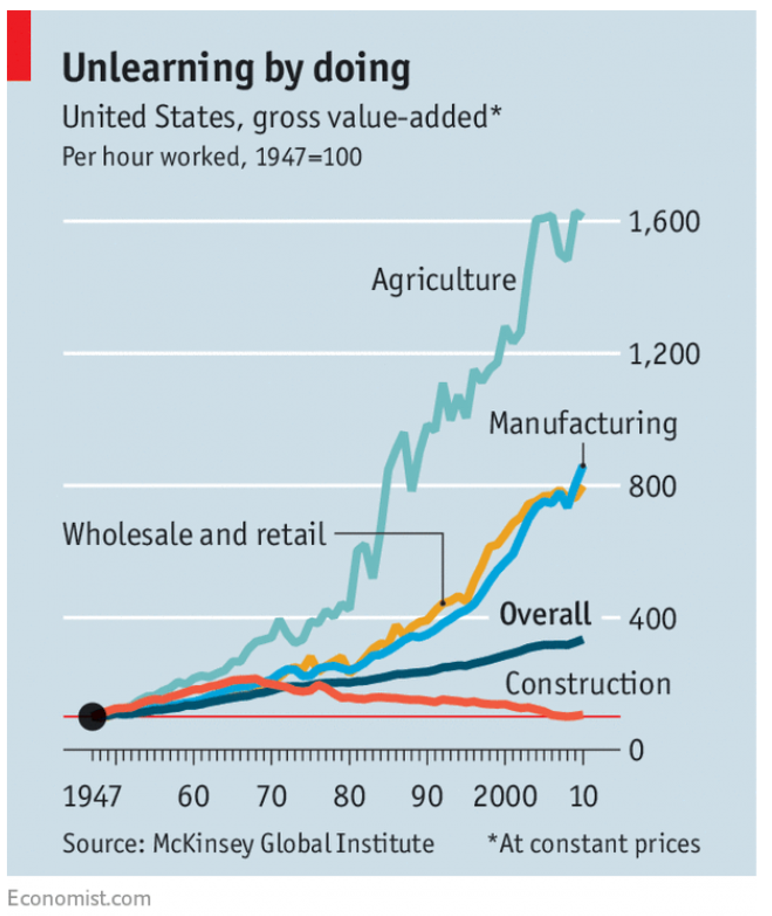
Figure 2.
Fischer’s Baubot is an automatic fastening robot which is used in combination with a digital BIM construction plan. It is an industrial robot on a vehicle with tracks that is meant to automate large construction site processes involving drilling and fastening, but since it is very heavy for small-scale construction, it needs specific use-cases to be successfully employed.
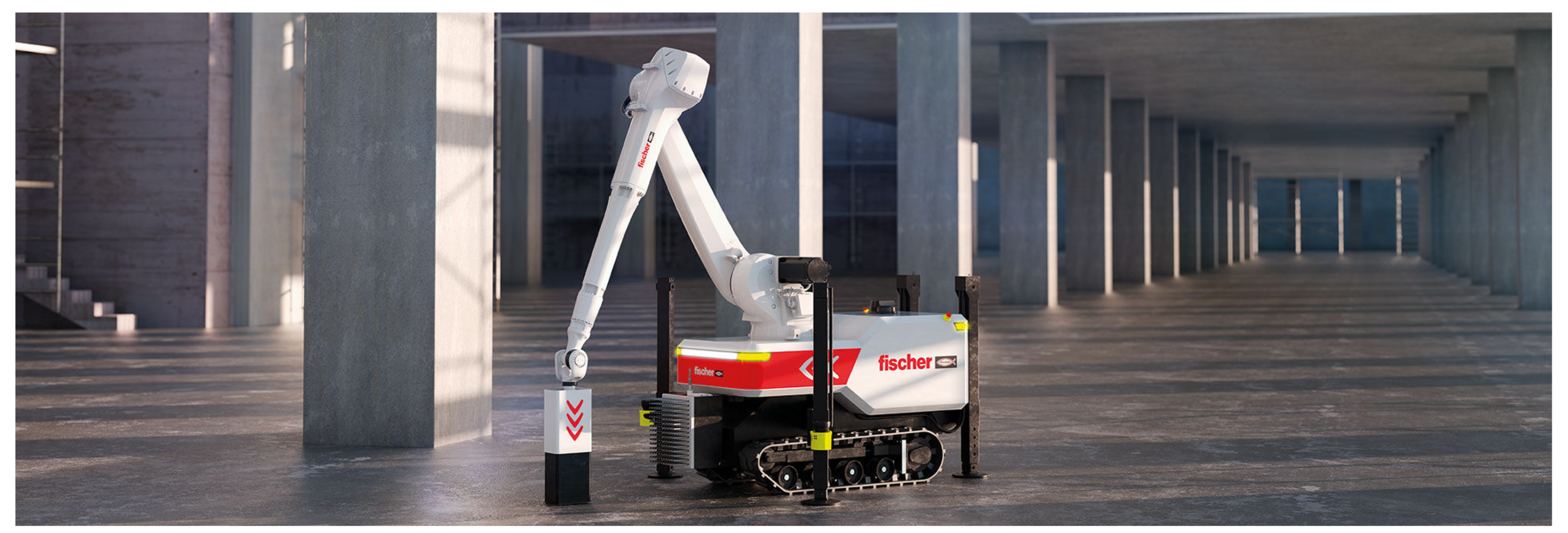
Figure 3.
Weinerberger’s WLTR masonry robot is an industrial robot on track placed in the construction site with a truck or a crane. It is aligned using a cross-line laser and monitors wall alignment with its sensors. It can pick up two bricks at a time and detect damaged ones, alerting the operator if misalignment occurs. The robot applies adhesive foam to the bricks before placing them with precision according to a virtual wall model. It communicates with an operator via a tablet and requires one supporting worker for tasks like supplying bricks and making adjustments. WLTR can move independently along the wall using a hydraulic lift and an electric pallet truck is included for floor movement. The system is very heavy and cumbersome for small-scale construction.
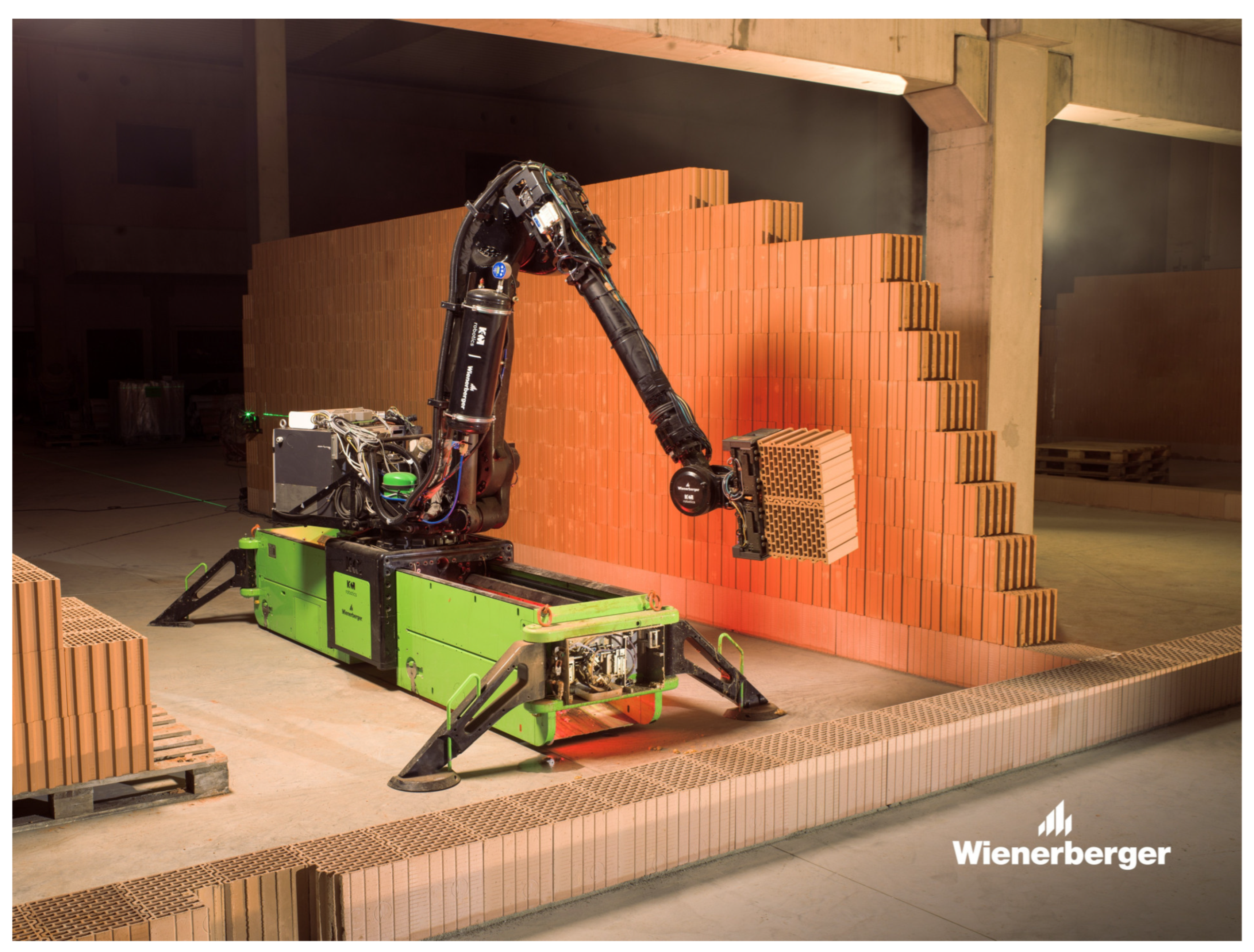
Figure 4.
CP Technology’s EKIP 21-04 robot semi-automates the insertion of tubular pre-assembled structural steel archs for tunneling. The arch is brought to the excavation front, lifted, and automatically opened with the robot: the central arm aligns it and the lateral arm places it correctly. Pre-installed supports replace chains, ensuring proper spacing, and a telescopic foot provides vertical compensation. Finally, the arch is filled with concrete to enhance its strength.
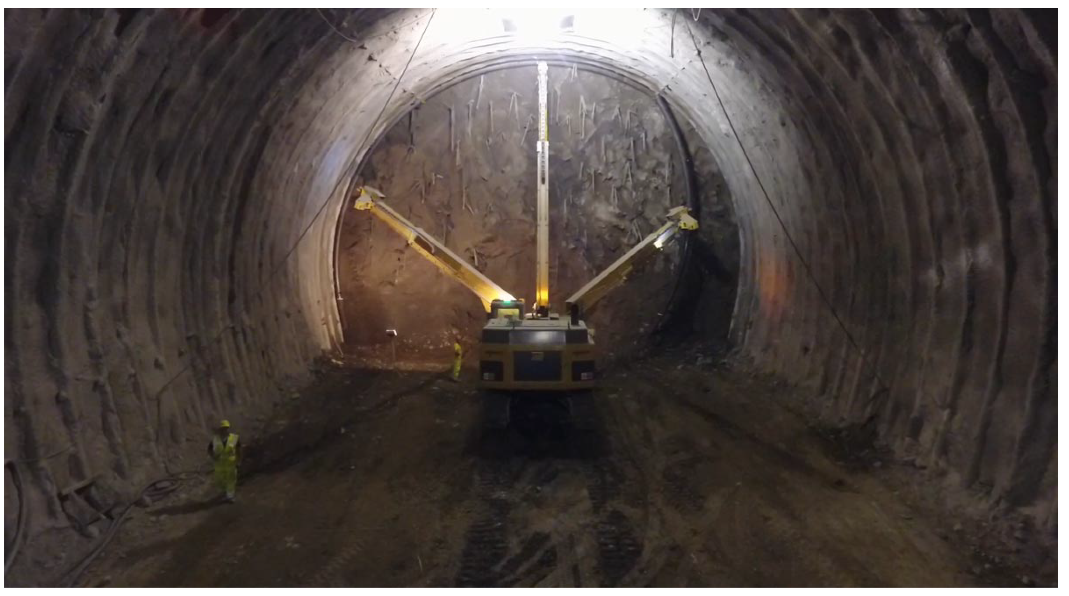
Figure 5.
Advanced Construction Robotics’ Tybot is an autonomous robotic system for rebar installation that self-navigates without pre-mapping and can be operational within two hours. It achieves over 1,200 ties per hour accommodating various rebar types and riding on existing edge forms or screed rails. It can tie rebar in multiple patterns and sizes, Tybot offers around of 25% schedule savings on construction projects.
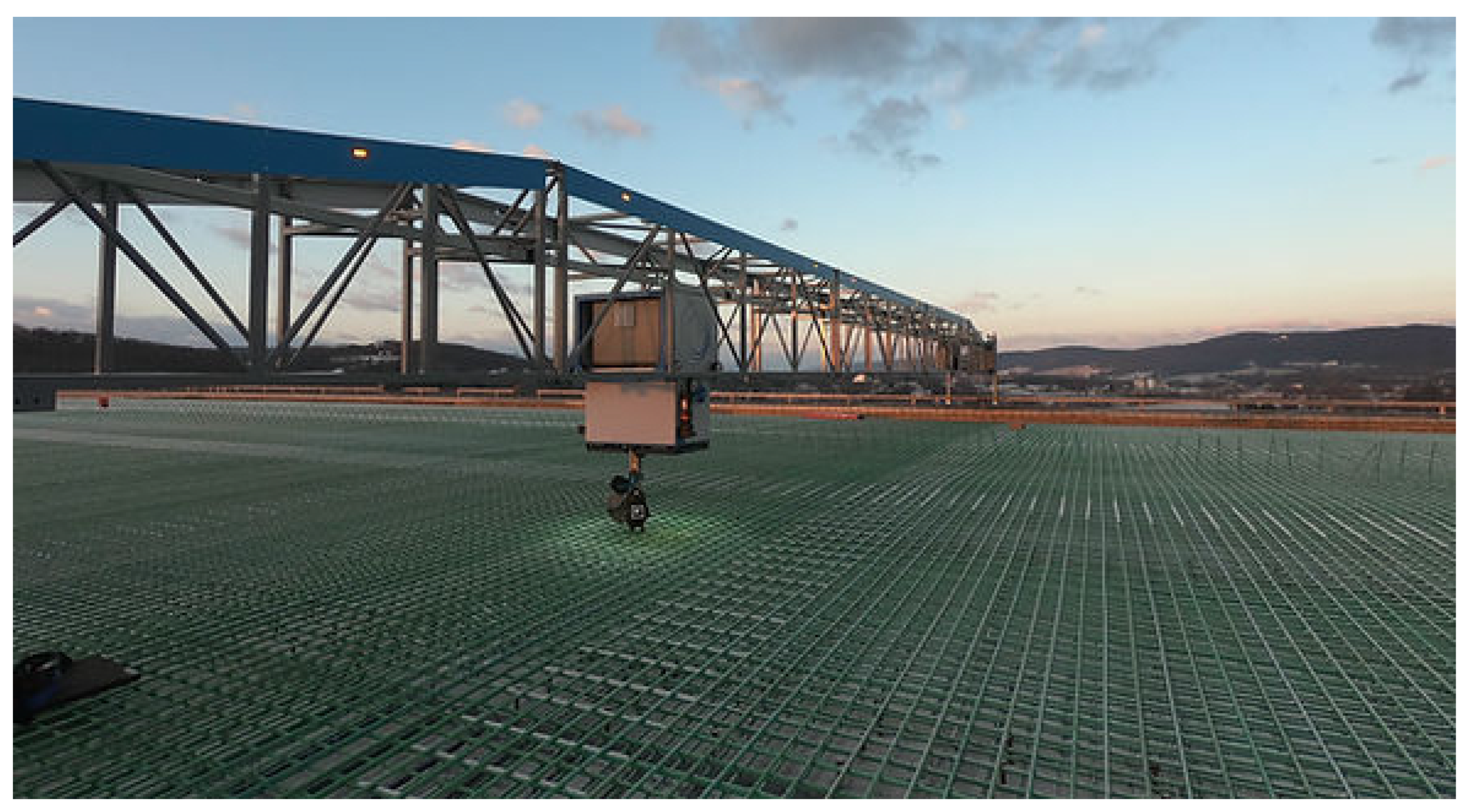
Figure 6.
The BRIX prototype in action at 2023 SAIE Construction Fair in Bari, Italy. This manufacturing system designed for on-site construction uses a rover and a robotic arm that work collaboratively with construction workers, who use augmented reality Microsoft Hololens2 for improved supervision and safety management. This integration highlights the effective combination of human skills and robotic efficiency in construction.
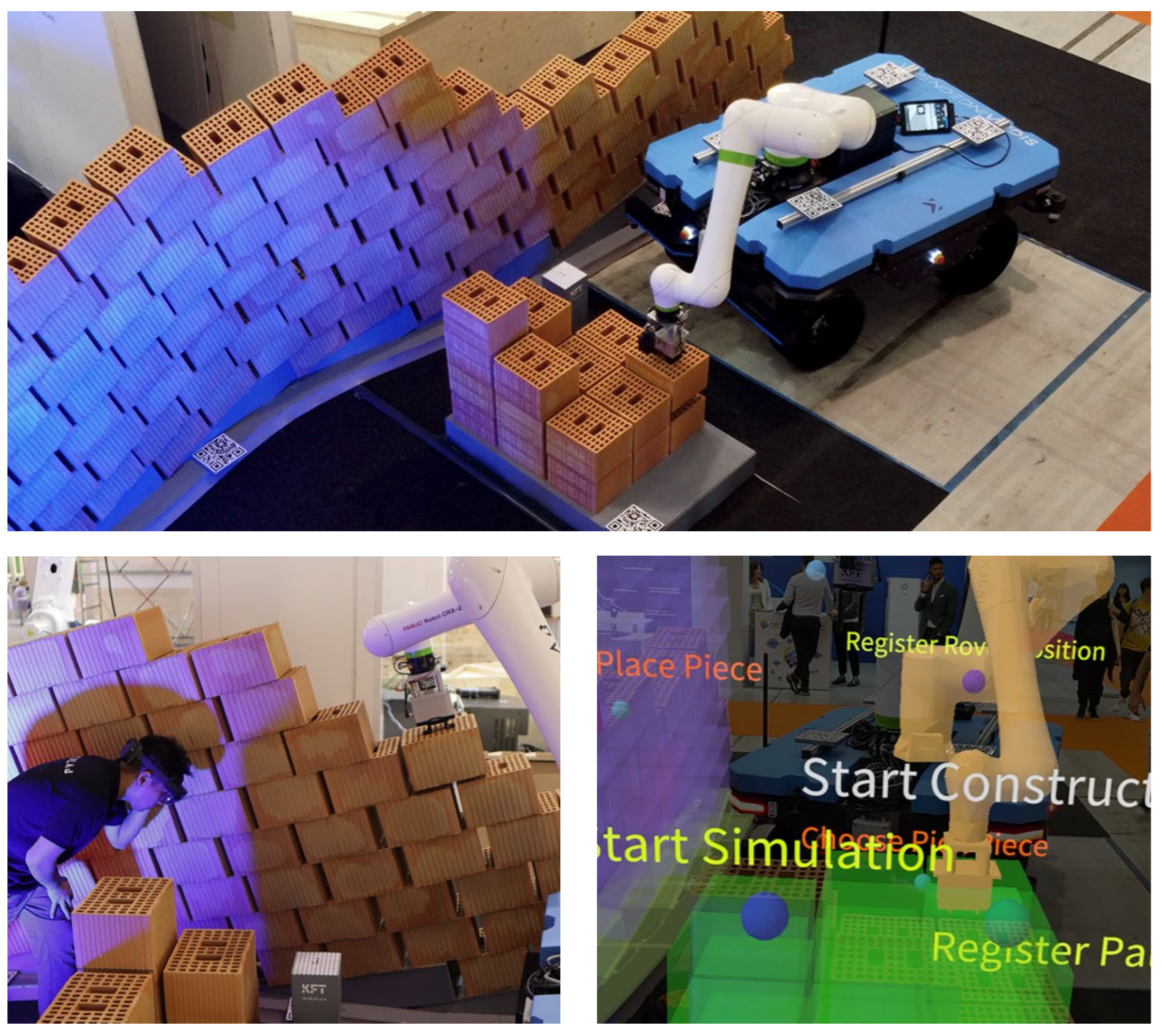
Figure 7.
The BRIX prototype in action at 2023 SAIE Construction Fair in Bari, Italy. The scanning clay block scanning sequence is based on the vision module and the markers position on the pallet.
Figure 7.
The BRIX prototype in action at 2023 SAIE Construction Fair in Bari, Italy. The scanning clay block scanning sequence is based on the vision module and the markers position on the pallet.
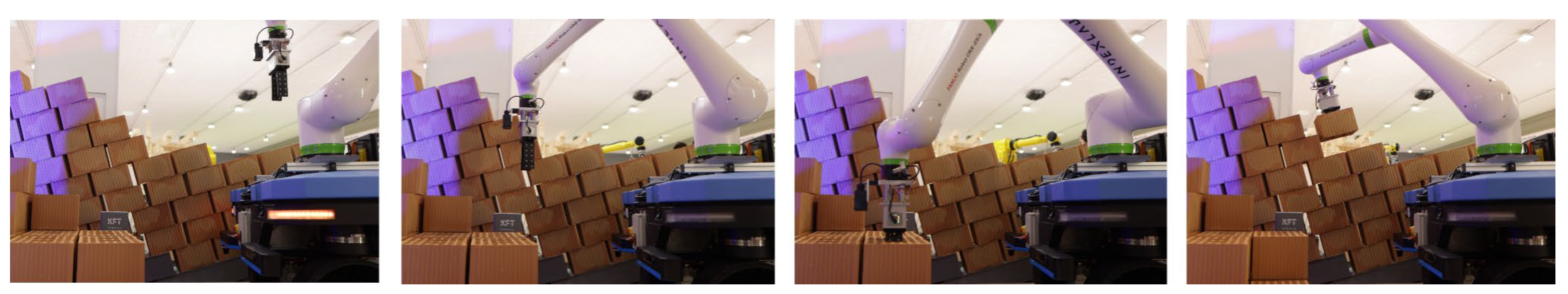
Figure 11.
The bounding boxes of Bric-a-Brick with both lifting column extended and robotic arm extended in the x, y and z directions
Figure 11.
The bounding boxes of Bric-a-Brick with both lifting column extended and robotic arm extended in the x, y and z directions
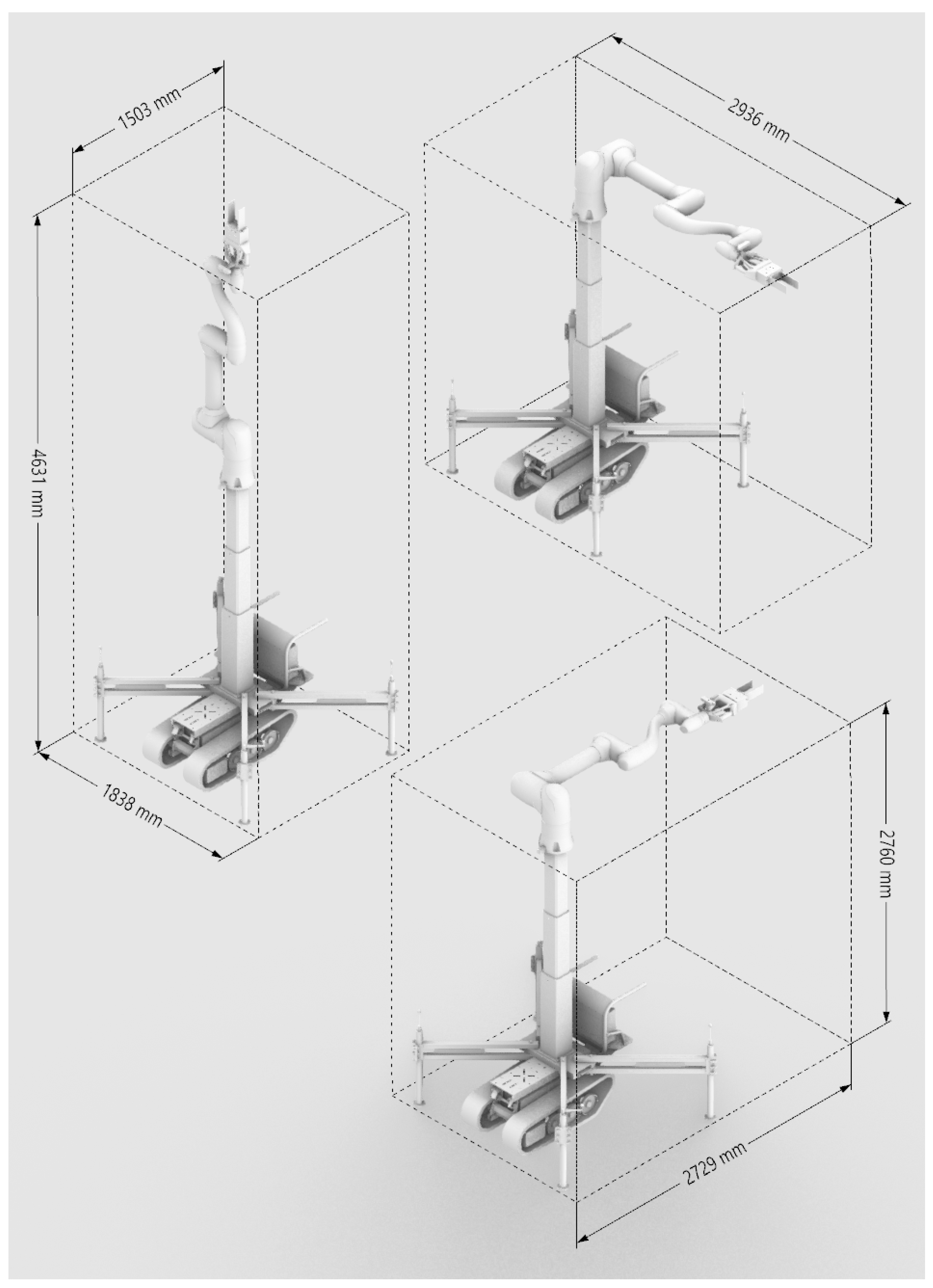
Figure 14.
Bounding box of the end-effector and overview of the new flange-gripper interface.
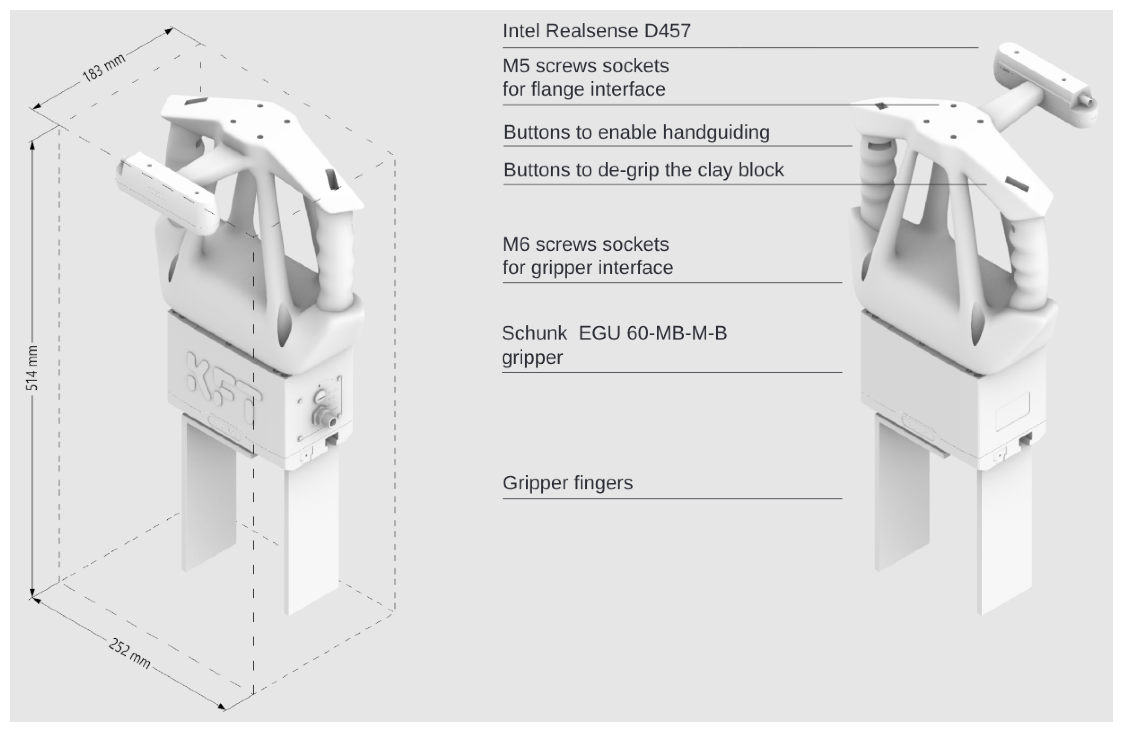
Figure 15.
Running the code on the notebook shows the 6 d-o-f pose of the clay block super-imposed on the RGB image of the camera stream.
Figure 15.
Running the code on the notebook shows the 6 d-o-f pose of the clay block super-imposed on the RGB image of the camera stream.
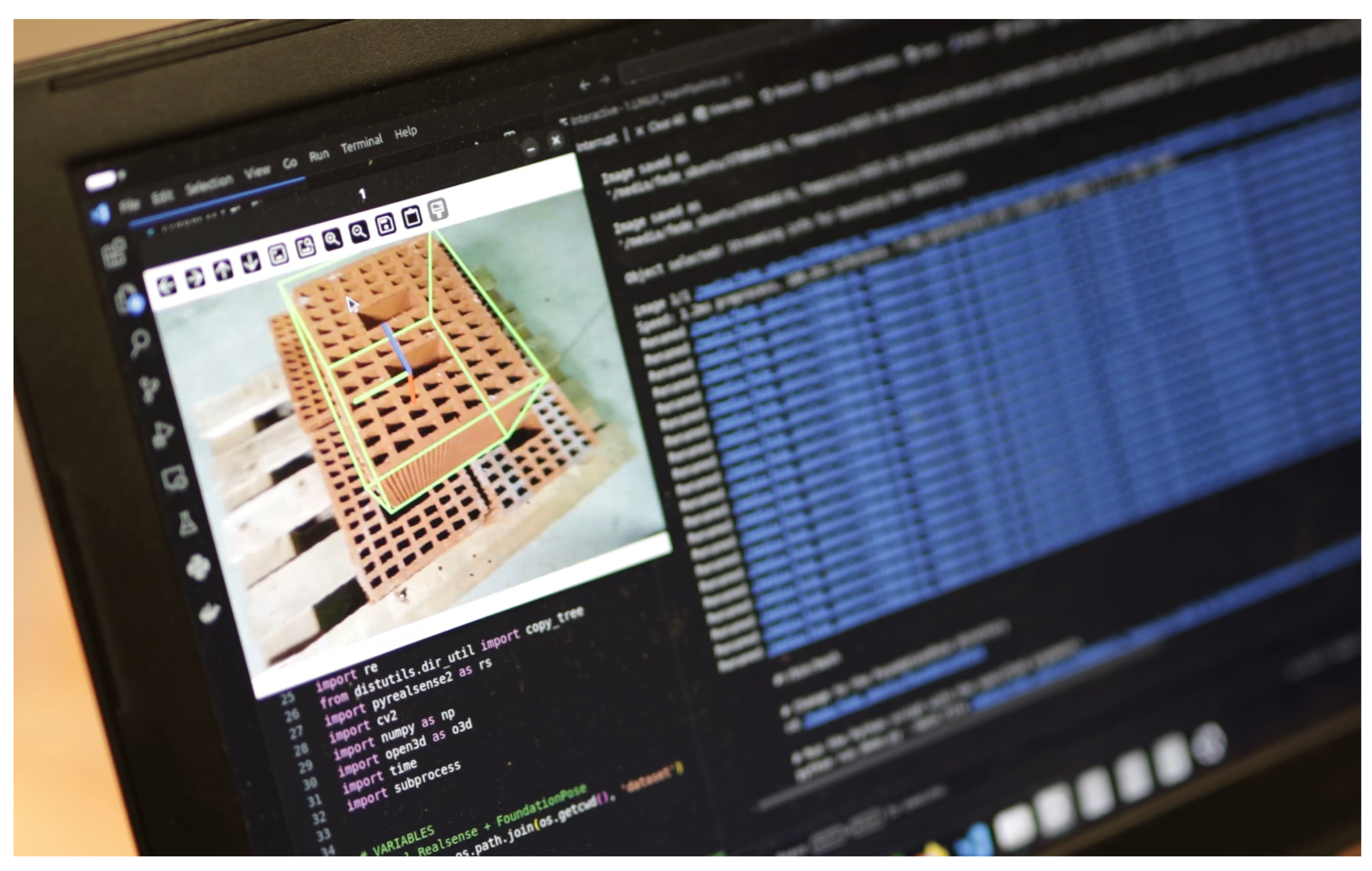
Figure 16.
The first tests of pick-n-place of Bric-a-Brick performed at INDEXLAB, Lecco.
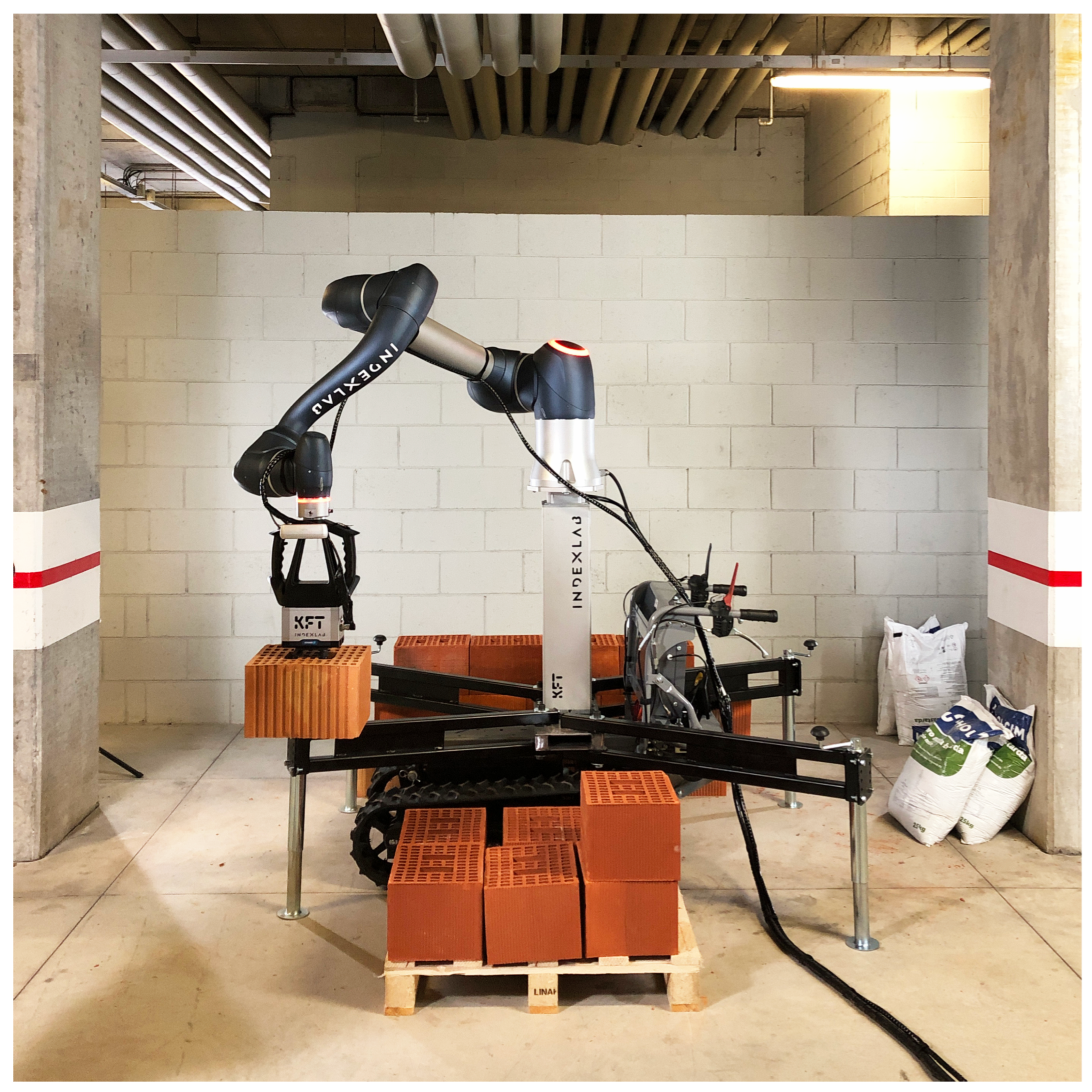
Figure 17.
Grasshopper3D visualization to show to the bricklayer how the wall patterning will be performed given a certain clay block cluster.
Figure 17.
Grasshopper3D visualization to show to the bricklayer how the wall patterning will be performed given a certain clay block cluster.
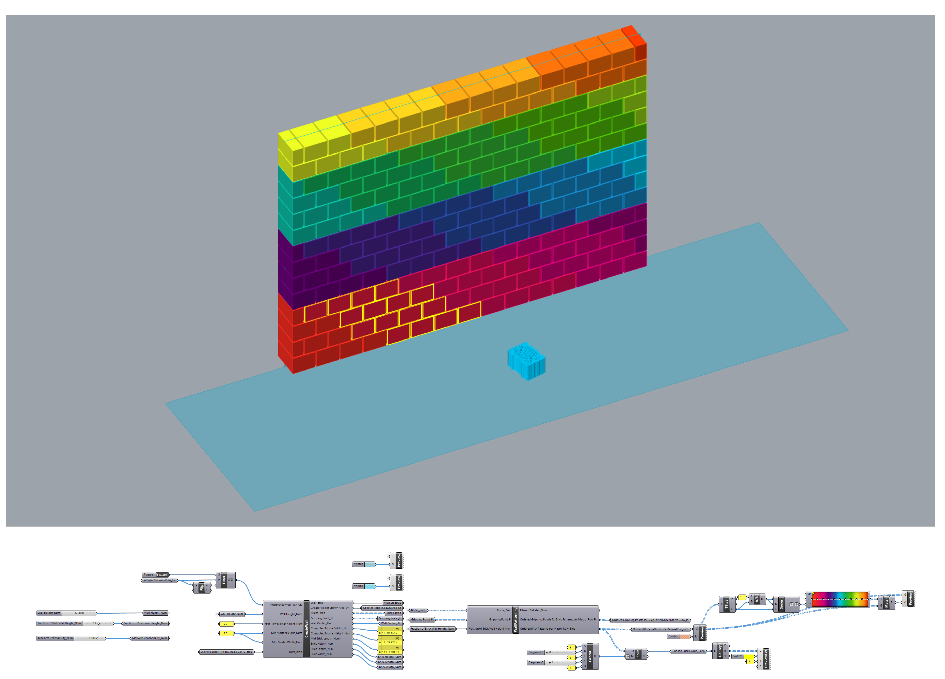
Figure 19.
In the ending phases of the construction process, the last clay block macro-rows are being built with the clay block pallet lifted and the lifting column fully up. The bricklayer is on a rolling scaffold or any other tool allowing to reach the robot height.
Figure 19.
In the ending phases of the construction process, the last clay block macro-rows are being built with the clay block pallet lifted and the lifting column fully up. The bricklayer is on a rolling scaffold or any other tool allowing to reach the robot height.
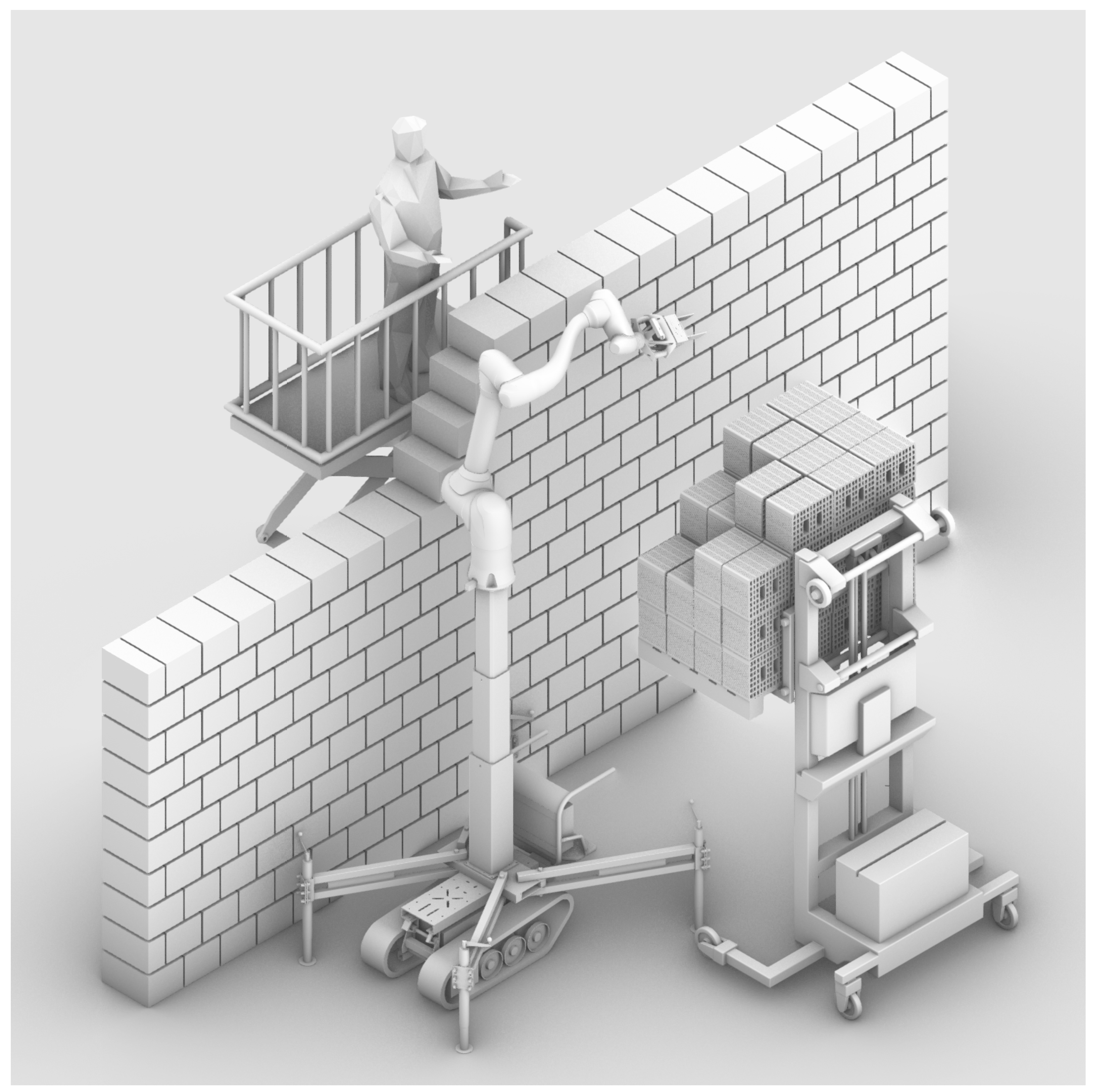

Table 1.
Timings per test cycle performed.
|
Guiding & positioning the wheelbarrow |
Scanning in spiral mode |
Sketching the region of interest (ROI) |
Recognizing the clay block |
Grasshopper3D simulation |
Picking up the clay block at 50 mm/s |
Moving the lifting column upward |
Placing the mortar |
Placing the clay block at 50 mm/s |
Moving the lifting column downward |
Robot moving back to the collaborative volume |
TOTAL | |
|---|---|---|---|---|---|---|---|---|---|---|---|---|
| Unloading the robot | 560 | |||||||||||
| Cycle 1 | 487 * | 143 | 10 * | 520 | 59 | 40 * | 0 † | 10 | 28 | 0 † | 37 | 1334 |
| Cycle 2 | 500 | 200 | 7 | 407 | 90 | 24 | 0 † | 10 | 23 | 0 † | 35 | 1296 |
| Cycle 3 | 429 | 187 * | 9 | 494 | 50 | 17 | 0 † | 8 | 26 | 0 † | 39 | 1309 |
| Cycle 4 | 462 * | 197 | 8 | 404 | 100 | 39 * | 0 † | 9 | 27 | 0 † | 36 | 1302 |
| Cycle 5 | 462 | 173 * | 10 * | 314 | 83 | 23 | 10 † | 9 | 18 | 10 † | 44 | 1156 |
| Cycle 6 | 482 * | 163 | 9 | 399 | 58 | 17 * | 10 † | 9 | 30 | 10 † | 44 | 1211 |
| Cycle 7 | 492 | 140 * | 10 | 255 | 88 | 31 | 10 † | 8 | 21 | 10 † | 45 | 1090 |
| Cycle 8 | 435 | 150 | 11 | 264 | 39 | 32 | 10 † | 9 | 27 | 10 † | 42 | 1029 |
| Cycle 9 | 471 * | 146 * | 8 | 361 | 50 | 29 | 10 † | 9 | 19 | 10 † | 45 | 1139 |
| Cycle 10 | 400 | 194 * | 8 | 333 | 57 | 36 * | 10 † | 9 | 15 | 10 † | 42 | 1094 |
| Cycle 11 | 426 | 180 | 7 | 313 | 59 | 15 * | 10 † | 9 | 29 | 10 † | 38 | 1096 |
| Cycle 12 | 424 | 173 | 11 | 271 | 42 | 37 | 10 † | 8 | 30 | 10 † | 38 | 1034 |
| Loading the robot | 670 |
Values marked with and asterisk (*) indicate that the attempt has been interrupted and re-performed again afterwards. Therefore, the timing refers to the second attempt. Values marked with a dagger (†) were not directly
measured during testing but were included to account for the use of the lifting column.
Disclaimer/Publisher’s Note: The statements, opinions and data contained in all publications are solely those of the individual author(s) and contributor(s) and not of MDPI and/or the editor(s). MDPI and/or the editor(s) disclaim responsibility for any injury to people or property resulting from any ideas, methods, instructions or products referred to in the content. |
© 2025 by the authors. Licensee MDPI, Basel, Switzerland. This article is an open access article distributed under the terms and conditions of the Creative Commons Attribution (CC BY) license (http://creativecommons.org/licenses/by/4.0/).
Copyright: This open access article is published under a Creative Commons CC BY 4.0 license, which permit the free download, distribution, and reuse, provided that the author and preprint are cited in any reuse.


