
Submitted:
18 June 2025
Posted:
19 June 2025
You are already at the latest version
Abstract
Human skeleton estimation technology is indispensable in several fields, including medical monitoring and sports biomechanics analysis. To overcome the drawbacks of traditional optical sensors and wearable devices, which include light sensitivity, privacy concerns, and usability challenges, we introduce a non-contact human skeleton estimation system that uses dual millimeter-wave (mmWave) Frequency-Modulated Continuous-Wave (FMCW) radar, termed as mm-HSE. We start by creating a dual-node mmWave FMCW radar data acquisition platform. In three distinct environments—a hallway, a meeting room, and an open space—data are collected from 12 participants, resulting in 30,000 range-angle maps using a customized signal processing pipeline. We then present a two-stage network for human skeleton estimation and optimization. In Stage 1, multi-scale spatiotemporal features are extracted from two input branches using a depthwise separable convolutional neural network augmented with a self-attention mechanism. Initial estimates of 21 skeletal keypoints are generated via a cross-modal attention fusion module. In Stage 2, we introduce a novel skeletal topology optimizer that leverages graph convolutional networks to refine keypoint positions. Experimental results demonstrate that mm-HSE achieves an average mean absolute error (MAE) of 2.78 cm. In cross-domain evaluations, the MAE remains consistently low at 3.14 cm, underscoring the model’s strong detection accuracy, environmental adaptability, and overall robustness.
Keywords:
human skeleton estimation
; mmWave FMCW radar
; range-angle maps
; cross-domain
1. Introduction
Next-generation human–machine interaction systems are rapidly transforming modern lifestyles, driven by advancements in millimeter-Wave (mmWave) radar miniaturization and edge computing technologies. As a core task in computer vision, high-precision Human Skeleton Estimation (HSE) plays a vital role in action recognition and behavior understanding by enabling the construction of three-dimensional motion representations of critical joints such as the head, shoulders, and elbows [1,2]. HSE has demonstrated its considerable potential in multiple areas, including medical monitoring, health, sports science, and smart home systems.
HSE approaches that are commonly used are divided into two categories: wearable device-based and optical sensor-based [3,4,5]. High-resolution motion data that is robust to lighting conditions is typically provided by inertial measurement units for wearable solutions [6]. In clinical settings where long-term monitoring is required, their reliance on body-worn devices presents challenges for user compliance [7]. The cost of equipment maintenance and discomfort from prolonged usage make large-scale deployment more difficult. Optical sensor-based approaches, like those that use camera systems combined with computer vision algorithms, can achieve high localization accuracy under favorable conditions [8], compared to other approaches. Nevertheless, their performance is highly prone to environmental lighting variations [9], and most importantly, the collection of biometric data raises growing worries about privacy protection under regulatory frameworks.
In an attempt to overcome the shortcomings of traditional HSE approaches, recent research has increasingly turned to alternative sensing approaches that use radio frequency signals [10]. Early efforts predominantly utilized commercial Wi-Fi devices operating in the 2.4/5 GHz frequency bands [11], where coarse-grained action recognition was achieved by analyzing time–frequency features extracted from channel state information. However, due to the relatively low carrier frequencies (e.g., 12.5 cm wavelength at 2.4 GHz), these systems suffer from strong diffraction effects, resulting in poor spatial resolution and making fine-grained skeletal localization particularly challenging. MmWave Frequency-Modulated Continuous-Wave (FMCW) radar has distinct advantages because of its superior physical properties.For instance, a 60 GHz mmWave radar, with a wavelength of approximately 5 mm, can achieve a minimum range resolution of 3.75 cm when operating with a 4 GHz bandwidth. The combination of a high center frequency and wide bandwidth is essential for enabling high-resolution, multidimensional motion perception, which is achieved through the accurate measurement of range, velocity, and angle [12,13]. In particular, the wide bandwidth plays a key role in determining range resolution, allowing the radar to precisely distinguish between closely spaced objects. This fine-grained resolution significantly enhances the accuracy of perception tasks across complex and dynamic environments. This modality confers three major benefits for HSE: 1) robust adaptability to varying environmental conditions, particularly under poor lighting; 2) enhanced privacy protection, as intermediate frequency spectrograms lack identifiable visual or biometric features; and 3) non-contact, long-term monitoring capabilities, which are especially suitable for scenarios such as continuous tracking in smart eldercare systems. Moreover, the recent industrial-scale development of compact and cost-effective mmWave FMCW radar chips [14] has substantially lowered deployment barriers, making this technology increasingly viable for consumer-grade and ubiquitous computing applications.
Current mmWave FMCW radar-based HSE techniques primarily follow two dominant paradigms. The first is the point cloud-based approach [15,16,17,18], which processes sparse radar point cloud data and leverages spatiotemporal modeling combined with attention mechanisms to estimate keypoint positions. While such methods preserve geometric structures and spatial topology [19], the inherent sparsity and noise of radar point clouds result in significant information loss, thereby limiting pose estimation accuracy. The second approach employs heatmap-based methods [20,21,22,23], where time–frequency representations—such as Range-Doppler (RD) or Range-Angle (RA) maps—are computed from intermediate frequency signals and used as inputs to deep neural networks [24]. These representations retain richer motion and frequency domain features, making them more informative than point clouds. However, several critical limitations remain in the current literature:
- Limited Model Generalization: Most prior studies have concentrated on optimizing performance within controlled experimental settings, with limited attention to cross-domain generalization or cross-user robustness. This restricts the applicability of current models in complex and dynamic real-world environments.
- Absence of Physiological Constraint Modeling: Existing methods typically lack explicit incorporation of human anatomical structures or kinematic constraints, which often leads to estimations that violate basic biomechanical principles. As a result, the predicted skeletal poses can deviate substantially from physically plausible human motion patterns.
To address the technical limitations of existing mmWave FMCW radar-based HSE systems, we propose a novel dual-radar skeleton estimation framework, termed as mm-HSE, which leverages collaborative sensing through a pair of orthogonally deployed mmWave FMCW radars. This orthogonal configuration greatly enhances observation coverage and cross-view complementarity, which enables richer spatial information acquisition from multiple angles. To support model development and evaluation, we collect a large-scale dataset comprising 30,000 raw ADC sequences from 12 participants across three representative indoor environments: a meeting room, a hallway, and an open space. To ingestion neural networks, a custom signal processing pipeline has been developed to turn raw intermediate frequency data into high-resolution RA maps. In terms of algorithms, mm-HSE utilizes a two-stage estimation architecture. In Stage 1, lightweight depthwise separable convolutional neural networks, augmented with self-attention modules, independently extract multi-scale spatiotemporal features from the dual radar inputs. An initial estimate of 21 skeletal key points is generated by fusing these complementary features using a cross-branch attention mechanism. In Stage 2, we introduce a skeletal topology optimizer based on Graph Convolutional Networks (GCN), which incorporates biomechanical priors—including bone length consistency and joint angle constraints—to refine the estimated skeleton into anatomically valid configurations. With this refinement, the final output is ensured to have high localization accuracy and structural plausibility across diverse motion scenarios.
We extensively evaluate the performance of the proposed mm-HSE system through a series of controlled experiments. First, to verify the feasibility of using RA maps for human skeleton estimation, we benchmark several classical deep learning architectures, including ResNet18 [25], Long Short-Term Memory (LSTM) [26], Convolutional Neural Networks-LSTM (CNN-LSTM) [27], and Mobile-friendly Vision Transformer (MobileViT) [28]. Results demonstrate that these baseline models can achieve estimation errors within 8 cm, confirming the effectiveness of RA maps as informative representations for radar-based HSE. Building upon this foundation, the mm-HSE framework further reduces the average error to 2.67 cm, significantly outperforming existing methods and highlighting the benefits of its dual-radar design and anatomical refinement modules. To assess model generalizability, we employed a stratified dataset partitioning scheme to evaluate the system under cross-domain and cross-user conditions. The mm-HSE system consistently maintained an average error below 4 cm in both settings, demonstrating strong robustness against environmental variability and individual user differences. In addition to accuracy benchmarking, this study also includes comprehensive analyses of critical performance factors, including keypoint-wise localization error, ablation of functional modules, and the influence of historical input frame length.
The remainder of this paper is organized as follows. Section 2 reviews related work and provides an overview of existing technologies for HSE using mmWave FMCW radar. Section 3 describes the data acquisition and processing pipeline, including the working principles of mmWave FMCW radar, the design of the sensing platform, and the generation of RA maps. In Section 4, we introduce the proposed mm-HSE framework, covering data augmentation strategies, feature extractor, fusion and initial estimation, and localization optimizer. Section 5 presents experimental results and analysis, including performance comparisons with baseline methods, evaluations under cross-domain and cross-user scenarios, and comprehensive ablation studies. Finally, Section 6 concludes the paper and outlines potential directions for future research.
2. Related Work
2.1. Point-Cloud Based
In the field of human skeleton estimation based on mmWave FMCW radar point clouds, the RadHAR system proposed by Akash et al. [12] represents a milestone. This system innovatively utilizes 5D point cloud data (including 3D spatial coordinates, Doppler velocity, and reflection intensity) from commercial radars, addressing the inherent sparsity of mmWave point clouds by constructing spatiotemporal voxel grids through a sliding time window. Experimental results demonstrate a classification accuracy of 90.47% across five daily activity recognition tasks, highlighting strong practical performance. Subsequently, Si et al. [13] developed the MARS system to address specific needs in rehabilitation healthcare. By employing intelligent 5D point cloud dimensionality reduction and 3D feature map transformation, MARS achieves 3D coordinate estimation for 19 skeletal keypoints with a Mean Absolute Error (MAE) of 5.87 cm. The mmMesh system proposed by Xue et al. [14] further advances the field by incorporating distance and reflection intensity into the 5D point cloud, forming an enhanced 6D representation. Integrating anchor modules and attention mechanisms, mmMesh achieves a mesh vertex reconstruction accuracy of 2.47 cm, setting a new benchmark for sparse point cloud processing.
For complex motion scenarios, Cao et al. [15] introduced the VirTeach framework, which proposes an innovative virtual point cloud augmentation strategy. By simulating point cloud distribution under rapid motion, this approach reduces MAE by 20% in vigorous motion sequences. Building on this, their subsequent mmPose-NLP system [16] adopts a natural language processing paradigm, utilizing a sequence-to-sequence architecture to process voxelized point cloud data, achieving a breakthrough MAE below 3 cm for 17 anatomical keypoints, demonstrating the potential of interdisciplinary approaches. Recent advances in temporal modeling are equally noteworthy. Shi et al. [17] overcome the limitations of single-frame data through sophisticated multi-frame 5D point cloud processing, combining bidirectional-LSTM networks with a reliability assessment module to filter noise artifacts, optimizing MAE to 2.84 cm. The Mikey system by Xie et al. [18] innovatively integrates adaptive GCN with Transformer architectures, maintaining robust performance (MAE < 6 cm) across diverse motion patterns. The mmHPE framework proposed by Wu et al. [19] employs a pioneering three-stage “detection-augmentation-estimation” pipeline, leveraging bounding box-guided point cloud augmentation and multi-scale networks to achieve an MAE of 4.5 cm while balancing computational efficiency for real-time applications.
2.2. FFT-Spectrum Based
In recent years, heatmap-based methods have garnered increasing attention for their ability to effectively exploit the rich spatial and temporal information embedded in radar signals. Within the domain of spectrogram-based representation, mmPose, proposed by Cao et al. [20], introduces a novel transformation of sparse point cloud data into customized three-channel RGB images that encode horizontal (range–azimuth–intensity) and vertical (range–elevation–intensity) features. Compared to the earlier RF-Pose system [21], mmPose reduces estimation errors in the X and Y axes by 1.0 cm and 1.3 cm, respectively. However, it also results in an increased error of 2.6 cm in the Z-axis, underscoring the persistent difficulty in accurate elevation estimation.
To address the challenges of multi-dimensional feature fusion, Xie et al. [22] proposed the RPM framework, which employs a dual-path heatmap input along with a spatiotemporal attention mechanism and a multi-dimensional fusion module. Cross-environment evaluations demonstrate that RPM consistently outperforms both RF-Pose and mmPose in terms of pose estimation accuracy. The HuPR framework introduced by Lee et al. [23] further advances the field by releasing the first public benchmark dataset for millimeter-wave radar-based pose estimation. HuPR utilizes four-dimensional heatmaps (range–Doppler–azimuth–elevation) and incorporates a GNN within a cross-modal learning framework to optimize skeletal predictions. This method achieves significantly improved average accuracy compared to RF-Pose. Notably, Rahman et al. [24] tackle the issue of kinematic inconsistency by introducing a tri-modal heatmap input processed via a CNN–LSTM hybrid architecture. Their system achieves an average estimation error of 6 cm across 13 keypoints, demonstrating the potential of mmWave radar-based pose estimation for clinical applications such as medical monitoring.
Through a systematic review of existing literature, several key challenges in the field of human skeleton estimation using mmWave radar remain insufficiently addressed: 1) The lack of comprehensive robustness evaluation limits model adaptability to complex and dynamic environments; and 2) most existing architectures neglect explicit modeling of human anatomical priors or kinematic constraints, which can lead to physically implausible or anatomically inconsistent pose estimations. These challenges collectively hinder the deployment of mmWave-based HSE systems in real-world applications, particularly in scenarios demanding high reliability, spatial coherence, and interpretability.
To address these limitations, we propose mm-HSE, as illustrated in Figure 1. The mm-HSE framework consists of three primary components: 1) a dual-radar data acquisition platform (detailed in Section 3.2), 2) a signal processing pipeline that converts raw ADC data into structured Range–Angle maps (Section 3.3), and 3) a two-stage neural architecture for skeletal keypoint estimation and anatomical refinement (Section 4).
3. Radar Data Acquisition and Processing
3.1. Operating Principle of FMCW Radar
The mmWave FMCW radar systems emit continuous signals whose frequency increases linearly over time, known as chirp signals [29]. The transmitted signal can be mathematically described as
where A represents the amplitude of the transmitted signal, denotes the initial frequency, represents the chirp rate with B being the bandwidth and the duration of the chirp, and is the initial phase.
When this signal reflects off a target located at a distance R and moving with a relative velocity v, the received signal experiences a time delay given by
where c is the speed of light. Consequently, the received signal can be expressed as
By mixing the transmitted and received signals, the system generates an Intermediate Frequency (IF) signal, whose frequency component is
Thus, the IF signal can be represented as
where encompasses the phase terms resulting from the mixing process.
In practical implementations, multiple chirp signals are transmitted sequentially. For the i-th chirp, received by the m-th antenna element, and sampled at the k-th point by the Analog-to-Digital Converter (ADC), the IF signal can be generalized as
where is the Doppler frequency component; corresponds to the range frequency component; represents the angular frequency component; is the sampling interval with being the number of samples per chirp; includes all constant phase terms; d is the spacing between adjacent antenna elements; is the angle of arrival of the target signal.
By performing two-dimensional Fourier transforms on the collected IF signals across multiple chirps and antenna elements, the system can extract the range, velocity, and angle information of targets, which are essential for subsequent detection and classification processes.
3.2. Experimental Setup and Data Acquisition
3.2.1. Data Acquisition Platforms
In this study, we develop a multimodal data acquisition system comprising the following components:
- mmWave FMCW Radar Sensing: As illustrated in Figure 2(a) and (b), the system integrates two commercial mmWave FMCW radars from Texas Instruments—the IWR1642BOOST and IWR6843ISK—as primary sensing devices. These radars are connected to the DCA1000EVM data capture module, enabling efficient acquisition and real-time transmission of raw radar signals.
- Optical Groundtruth Annotation: As shown in Figure 2(c), the system employs the Microsoft Kinect V2 optical sensor as the groundtruth annotation device. This sensor provides high-precision three-dimensional coordinates for 21 skeletal joints, as depicted in Figure 2(d), as a reliable reference for subsequent algorithm training.
- Synchronization and Control System: Two high-performance computers functioning as the control center manage the entire system. Time synchronization across multiple data sources is achieved using the Network Time Protocol (NTP), enabling millisecond-level timestamp alignment and ensuring temporal consistency among different modalities.
- Radar Configuration: The core parameters of the two radars are optimized as shown in Table 1. The IWR1642BOOST operates in the 77 GHz mmWave band, employing a 2-transmitter, 4-receiver antenna array design, which forms 8 equivalent channels in the azimuth dimension through MIMO virtual aperture technology. The IWR6843ISK operates at 60 GHz, featuring a 3-transmitter, 4-receiver antenna array to enhance elevation resolution. Notably, other parameters remain consistent across both devices: the effective bandwidth is set to 3.072 GHz, the number of samples per frame is fixed at 256, and the frame period is strictly controlled at 50 ms.
3.2.2. Data Acquisition and Action Design
To facilitate data alignment and spatial calibration, the IWR1642BOOST and Kinect V2 are precisely adjusted to a reference height of 1.2 m in the vertical (y) dimension, while the IWR6843ISK is positioned at 0.9 m to create a height difference. In the horizontal (x) layout, the IWR1642BOOST is placed 0.6 m from the Kinect V2 center and 0.25 m from the IWR6843ISK, forming a stable triangular observation network. During installation, high-precision tripods and a digital level are used to ensure that the axial deviation of each sensor remains below 0.5 degrees, minimizing systematic errors.
The experiment involves 12 volunteers participating in daily activity data collection across three typical environments: a meeting room, a hallway, and an open space. Volunteers are required to perform activities within a distance of 2.5 m to 3.5 m from the acquisition hardware. The experiment captures data for several daily actions, including walking, left-hand waving, right-hand waving, simultaneous waving with both hands, and jumping. Each volunteer performs two rounds per action, with each round consisting of 50 frames, resulting in a 2.5-second acquisition duration per action.
3.3. Signal Processing Pipeline for RA Map Generation
The transformation of raw IF signals into RA maps involves a structured sequence of signal processing steps, each designed to extract specific target information. The RA map, with range on the x-axis and azimuth angle on the y-axis, represents the intensity of target reflections and is instrumental in target detection and imaging. The processing pipeline encompasses the following stages:
- Range Processing: Perform a Fast Fourier Transform (FFT) along the fast-time axis (i.e., within each chirp) to obtain the range profilewhere denotes the IF signal for the i-th chirp, m-th antenna element, n-th sample within a chirp; and k indexes the range bins.
- Doppler Processing: Apply an FFT along the slow-time axis (i.e., across chirps) to generate the Range-Doppler mapwhere is the number of chirps per frame, and p indexes the Doppler bins.
- Angle Processing: Perform an FFT across the multiple receiver antennas to resolve the angular position of targetswhere is the number of receiver antennas, and q indexes the angle bins.
- RA Heatmap Generation: Generate the RA heatmap by extracting the zero-Doppler slice or integrating over the Doppler dimension of the radar data cube
This heatmap provides a two-dimensional representation of target reflections, facilitating subsequent tasks such as object detection and classification.
4. Methodology
We introduce mm-HSE , a two-stage framework for human skeleton estimation leveraging cooperative sensing from dual mmWave FMCW radars. As illustrated in Figure 1, the framework comprises four integral modules forming a comprehensive end-to-end processing pipeline. First, the data augmentation module employs multi-dimensional enhancement strategies tailored to the characteristics of mmWave FMCW radar data, effectively improving the model’s generalization capabilities. Second, the feature extractor module utilizes a hybrid network architecture that combines depthwise separable convolutions with self-attention mechanisms to efficiently learn feature representations from heterogeneous data collected by different radars. Third, the cross-modal fusion and initial estimation module applies a cross-attention-based feature fusion approach to fully exploit the complementary information from the dual radar inputs, generating an initial estimation of the human skeleton. Finally, the localization optimizer module incorporates human kinematic constraints to refine the initial estimation through a graph optimization network, significantly enhancing the accuracy and plausibility of the skeleton estimation.
4.1. Data Augmentation
To enhance the robustness and generalization capability of the model against sensor noise and target motion variability, we employ two data augmentation strategies: temporal augmentation and 3D keypoint rotation. These augmentations are applied to the radar heatmap sequences and their corresponding groundtruth labels, respectively.
- Temporal Augmentation: Each radar heatmap sequence comprises T consecutive frames, with each sample consisting of 5 frames. To introduce temporal variability, we apply random shuffling to the frame order with a probability of 0.5. Specifically, we generate a random permutation , where denotes the set of all permutations of T elements, and reorder the frames accordingly to obtain the augmented sequence . This process encourages the model to learn temporal-invariant features, thereby improving its robustness to dynamic motion patterns.
-
3D Keypoint Rotation: To account for variations in target orientation, we apply spatial transformations to the groundtruth 3D keypoints. With a probability of 0.5, we sample a random rotation angle from the interval and rotate the keypoints around the vertical (y) axis. The rotation is implemented using the standard 3D rotation matrix for the y-axisThe transformed keypoints are then computed as , where represents the original keypoint coordinates, and corresponds to the number of keypoints. This transformation maintains the skeletal structure while enhancing the model’s adaptability to changes in target orientation.
The augmented radar heatmap sequences and keypoints are subsequently fed into the feature extraction stage, where B represents the batch size, C indicates the number of channels, and specifies the heatmap resolution.
4.2. Feature Extractor
The augmented dual-channel radar heatmap sequences are first reshaped into a tensor of shape . We then propose a feature extraction network that integrates depthwise separable convolutions and a multi-head self-attention mechanism, aiming to efficiently capture both spatial structures and temporal dynamics from the radar sequences. As illustrated in Figure 4(a), the network comprises four depthwise separable convolutional blocks, each consisting of a depthwise convolution, a pointwise convolution, batch normalization, and a ReLU activation.
For each frame , the depthwise convolution with a kernel models the spatial features of each channel independently, followed by a pointwise convolution that fuses inter-channel information. The resulting high-dimensional spatial feature is denoted as .
To model the temporal dependencies across the sequence, we introduce a temporal modeling module based on multi-head self-attention. Each frame-level spatial feature is flattened and reorganized into a temporal sequence, yielding , where D denotes the dimensionality of the flattened feature. Query, key, and value vectors are then generated through linear projections and partitioned into four attention heads (head_dim = 4). The multi-head attention mechanism captures cross-frame dependencies and adaptively emphasizes critical motion frames, producing a temporal feature representation with dimensionality .
Finally, a learnable projection matrix is applied to compress the high-dimensional features into a compact representation . The above process is applied independently to both radar channels, resulting in two feature sequences , which are then fed into the subsequent feature fusion module.
4.3. Fusion and Initial Estimation
Following temporal feature extraction, we design a cross-view attention-based fusion module to effectively integrate complementary spatial information from the azimuth and elevation radar channels. As shown in Figure 4(b), this module enables explicit bidirectional interaction between the two branches, enhancing the network’s ability to capture motion-sensitive frames and structural patterns from multiple perspectives. Specifically, the cross-attention mechanism allows the network to effectively learn and fuse spatial features across the two radar views, facilitating better context alignment and feature interaction between the azimuth and elevation channels.
The extracted temporal feature sequences and are first projected into a shared embedding space through separate linear layers. The projected features are then fed into a symmetric cross-attention mechanism, where each branch serves as the query vector and attends to the other branch’s features as keys and values. This dynamic attention process enables the model to capture the most informative frames that contain key spatial cues from either view. By attending to complementary features from both views, the model learns to emphasize spatially critical areas in the radar signal, such as structural relationships between key points, improving the robustness of feature fusion in diverse radar conditions.
This interaction facilitates information exchange across views, allowing the model to emphasize frames containing critical spatial or temporal cues and to establish frame-level contextual alignment between modalities. The enhanced sequences and are obtained through multi-head attention, which allows the model to capture more fine-grained dependencies across multiple heads. Global feature representations and are computed by averaging over the temporal dimension. The two global features are concatenated and passed through a fully connected layer to produce the fused representation , which integrates complementary information from both views.
To map the fused semantic representation to the 3D keypoint space, we introduce a lightweight regression head composed of a ReLU activation followed by two linear layers. This regression module transforms into the coarse pose estimation , where N denotes the number of keypoints. The predicted coordinates serve as a reliable initialization for subsequent refinement, providing a structurally informed pose prior that facilitates improved accuracy and convergence in the final estimation stage.
4.4. Localization Optimizer
To further enhance the accuracy and anatomical plausibility of the coarse pose estimate , we design a refinement module as illustrated in Figure 4(c). This module, referred to as the Estimation Optimizer, consists of a graph-based feature encoder followed by a constraint projection step, producing the final refined pose .
4.4.1. Graph-Based Encoding
The first part of the module leverages a two-layer GCN to model structural dependencies among keypoints. Each GCN layer is followed by a ReLU activation to introduce non-linearity. The graph topology is defined by a fixed adjacency matrix that encodes the kinematic structure of the human body. A graph pooling operation aggregates contextual features, and a linear layer transforms the output into updated 3D coordinates .
4.5. Constraint Projection
To enable end-to-end training while enforcing anatomical constraints in a progressive manner, we design a differentiable module with three sequential steps: bone length refinement, joint angle refinement, and Residual Fusion. The module takes the GCN-encoded keypoints and features as input, producing the final refined pose .
4.5.1. Bone Length Refinement
A two-layer MLP predicts residual adjustments to enforce bone length constraints
where has 64 hidden units with ReLU activations, outputting residuals . For each bone connection , where contains 20 predefined bone pairs, we compute the predicted bone length
Target bone lengths are predicted by
where are GCN features. The bone length loss is
4.5.2. Joint Angle Refinement
A second two-layer MLP refines to enforce joint angle constraints
with the same MLP architecture. For each triplet , where contains four predefined angle constraints, we compute the cosine of the predicted angle
with for numerical stability. Target angles are predicted by:
The angle loss is
4.5.3. Residual Fusion
To balance constraint-based correction with the stability of the initial prediction, we apply the Residual Fusion mechanism. The final refined pose is computed as a convex combination of the coarse estimate and the constraint-refined pose
where is a fusion weight hyperparameter. This fusion ensures adaptive refinement while maintaining robustness.
4.5.4. Total Loss
The overall loss combines keypoint regression with anatomical constraints
where measures the error against ground-truth keypoints , and , are hyperparameters.
4.6. Evaluation Metrics
To evaluate the accuracy of the predicted 3D skeleton, we employ two widely adopted metrics, which provide interpretable and robust measurements of keypoint localization performance
- Mean Absolute Error (MAE): This metric quantifies the average L1 distance between the predicted keypoints and the groundtruth keypoints across all samples, joints, and spatial coordinate dimensions .where and denote the predicted and groundtruth coordinates of the n-th keypoint in the b-th sample, along the x, y, and z axes respectively.
- Root Mean Square Error (RMSE): This metric measures the average L2 error between predicted and groundtruth coordinates along the three spatial dimensions.
Each keypoint is defined by its position in centimeters, with x indicating the horizontal axis, y the vertical axis, and z the depth.
5. Experimental Results and Analysis
5.1. Experimental Setup
All experiments were conducted on a high-performance computing platform equipped with an AMD EPYC 7742 CPU and eight NVIDIA V100 GPUs. The implementation was based on the PyTorch 1.9.0 deep learning framework. To accelerate training, data parallelism was employed across the available GPUs. The dataset used in this study is a self-constructed radar-based human skeletal heatmap dataset, where each sample comprises an azimuthal heatmap, an elevational heatmap, and the corresponding 3D keypoint annotations.
A stratified sampling strategy was adopted to divide the dataset into training and testing subsets in an 8:2 ratio, with 80% of the data allocated for training and the remaining 20% reserved for evaluation. To assess the generalization performance of the proposed method, two types of domain adaptation scenarios were explored: (1) cross-domain, where the model was trained on one scene and tested on two distinct scenes; and (2) cross-user, where training was conducted on data from two individuals and testing on data from nine different individuals. During training, the data augmentation techniques detailed in Section 4.1, including temporal sequence shuffling and 3D keypoint rotation, were applied. No augmentation was applied during inference to maintain the authenticity and objectivity of the evaluation.
The model was trained using a batch size of 32 and an initial learning rate of 0.001. A step-based learning rate scheduler was applied, decaying the learning rate by a factor of 0.5 every 20 epochs. The optimization was carried out using the Adam optimizer for up to 100 epochs. Early stopping was triggered if the validation loss failed to improve for 20 consecutive epochs. In the residual fusion module (Equation (19)), the fusion weight w was set to 0.6 to balance spatial accuracy and anatomical regularization. The model dimensionality was set to 64, while the hidden dimension of the GCN was set to 128. Both the self-attention and cross-view attention modules were configured with 4 attention heads.
5.2. Comparative experiment
To validate the feasibility of performing HSE based on mmWave FMCW radar RA maps, we conduct comparative experiments using four representative deep learning models: ResNet18 (2D convolutional backbone) [25], LSTM (temporal sequence modeling) [26], CNN-LSTM (spatial–temporal hybrid model) [27], and MobileViT (a lightweight vision transformer) [28]. The results are presented in Figure 5 with performance evaluated using MAE and RMSE across horizontal, vertical, and depth axes. Among the baselines, ResNet18 yielded the highest error rates, with an average MAE of 5.86 cm and RMSE of 7.98 cm, particularly underperforming in depth estimation (MAE = 7.18 cm; RMSE = 9.27 cm). In contrast, CNN-LSTM and MobileViT showed significantly better performance. CNN-LSTM achieved an MAE of 4.36 cm and RMSE of 6.38 cm, while MobileViT reached an MAE of 4.83 cm and RMSE of 6.62 cm, indicating that architectures capable of modeling either temporal sequences or global attention contribute meaningfully to pose estimation accuracy from radar signals.
Further, Figure 5 shows that our proposed method, mm-HSE, achieves substantial improvements over all baselines. Specifically, mm-HSE attains the lowest average MAE of 2.78 cm and RMSE of 4.35 cm, with consistently superior performance across all axes (e.g., horizontal MAE = 2.24 cm; depth RMSE = 5.51 cm). These results validate the effectiveness of our dual-radar cooperative design and the proposed skeletal constraint refinement strategy. By integrating anatomical priors and leveraging cross-radar spatial complementarity, mm-HSE significantly enhances the structural accuracy and robustness of 3D skeletal keypoint localization from sparse radar reflections.
To further assess the effectiveness of the proposed mm-HSE framework, we conduct comparative evaluations against four representative radar-based 3D human pose estimation methods: RF-Pose3D [21], RPM [22], mmPose [20], and HuPR [23]. As summarized in Table 2, mm-HSE consistently achieves the lowest MAE across all spatial dimensions—horizontal, vertical, and depth—outperforming all baselines by a considerable margin. Compared to RF-Pose3D and mmPose—the two next-best performing methods with average MAE of 4.37 cm and 4.47 cm, respectively—mm-HSE achieves a relative error reduction of 36.4% and 37.8%. The improvement is even more pronounced when compared to HuPR, with a 59.2% reduction in average MAE. Additionally, mm-HSE consistently outperforms all methods on individual spatial axes: the horizontal, vertical, and depth errors are 2.24 cm, 2.75 cm, and 3.36 cm, respectively, whereas other methods show imbalanced or significantly higher errors—e.g., mmPose exhibits a horizontal MAE of 7.5 cm, and RF-Pose3D struggles in the depth dimension.
We observe that the mm-HSE model demonstrates superior performance compared to baseline methods. However, direct comparisons must be interpreted cautiously due to potential biases arising from variations in dataset size, training/test splits, and evaluation protocols. Specifically, our dataset comprises 30,000 samples collected from 12 participants, which is relatively limited for training deep learning models. Moreover, the high accuracy achieved may partially stem from the homogeneity of participants’ body types and the constrained range of actions in the dataset, potentially limiting the model’s generalizability. These findings motivate future efforts to expand our data collection strategy, incorporating a larger and more diverse participant pool with a broader range of actions to enhance the model’s robustness and applicability. Nevertheless, as demonstrated in the feasibility experiments shown in Figure 5, mm-HSE consistently outperforms traditional approaches under a standardized evaluation pipeline, providing compelling evidence of its efficacy.
To systematically evaluate the spatial reliability and anatomical consistency of the proposed mm-HSE model, we further analyze the distribution of localization errors across all 21 skeletal keypoints, as shown in Figure 6. Both MAE and RMSE were computed along the horizontal, vertical, and depth dimensions. The results reveal that the horizontal and vertical directions exhibit relatively stable error distributions across keypoints, with minor fluctuations and no extreme outliers. This suggests that the proposed spatial attention and dual-view fusion mechanisms effectively enhance pose estimation performance in these axes. In contrast, the depth axis demonstrates greater variability, particularly around central body joints such as the spine, hips, and shoulders (e.g., keypoints 9–15). This phenomenon is likely attributable to the limited resolution of millimeter-wave radar in the radial direction, compounded by multipath interference and occlusion effects. Despite these challenges, the average error across all joints remains consistently low, underscoring the model’s robustness in full-body 3D reconstruction tasks. These findings not only validate the mm-HSE’s precision in anatomical space but also highlight depth modeling as a critical area for future enhancement in radar-based skeletal keypoint estimation..
5.3. Cross-Domain Experiment
To evaluate the generalization capability of the proposed mm-HSE model, we conduct experiments under both Cross-Domain (CD) and Cross-User (CU) settings. Specifically, CD_1 refers to training on data collected in the meeting room, CD_2 corresponds to hallway data, and CD_3 represents open space training. The CU setting involves training with data from two volunteers and testing on unseen users. The evaluation is performed along three spatial axes—horizontal, vertical, and depth—using MAE and RMSE as performance metrics. The results are summarized in Figure 7.
In the cross-domain, mm-HSE demonstrates consistently low and stable localization errors across all three domains. The average MAE across CD_1, CD_2, and CD_3 is 3.34 cm, 3.17 cm, and 3.14 cm, respectively, with a maximum variation of only 0.20 cm. This stability highlights the robustness of the proposed spatiotemporal modeling strategy and the dual-radar fusion mechanism in adapting to different environmental contexts. Furthermore, the performance improves progressively from CD_1 to CD_3, suggesting that the model benefits from domain-agnostic learning and generalizes well to previously unseen distributions.
In contrast, the cross-user scenario presents a more challenging setting. The average MAE increases to 3.86 cm, representing a relative degradation of 22.9% compared to the best cross-domain result. The RMSE exhibits a similar trend, rising to 5.99 cm in CU from an average of 5.27 cm in CD_3. This degradation is particularly pronounced along the depth axis (MAE = 5.11 cm, RMSE = 7.34 cm), which may be attributed to user-specific motion habits and body morphology variations that are difficult to generalize across subjects.
Despite these challenges, the model maintains relatively stable and low errors in the horizontal and vertical dimensions across all scenarios, typically within the 2.5–3.2 cm MAE range. These findings suggest that while mm-HSE offers strong generalization across spatial environments, future improvements may be focused on enhancing its robustness to inter-user variability, especially in depth estimation.
5.4. Ablation Experiment
5.4.1. The Influence of the Module
To quantitatively assess the contribution of each component in the mm-HSE framework, we conduct a detailed ablation study, as summarized in Table 3. The baseline model, which includes only the Stage 1 architecture without any auxiliary modules, yields an average error of (MAE = 7.34 cm, RMSE = 9.86 cm). Upon incorporating the data augmentation strategy described in Section 4.1, the error is substantially reduced to (MAE = 5.86 cm, RMSE = 8.04 cm), confirming its role in improving generalization and mitigating overfitting.
Further enhancements are observed when the multi-view fusion module is introduced. While fusion alone (without Stage 2) improves performance to (MAE = 4.62 cm, RMSE = 7.19 cm), a more substantial improvement is achieved by activating Stage 2 alone (MAE = 3.84 cm, RMSE = 5.83 cm), indicating that the anatomically constrained refinement plays a more decisive role than early-stage fusion. Notably, the full configuration—comprising data augmentation, Stage 1, fusion, and Stage 2—achieves optimal results with (MAE = 2.78 cm, RMSE = 4.35 cm). This corresponds to a 62.1% and 55.9% relative improvement in MAE and RMSE over the baseline, and a 27.6% and 25.4% gain over the second-best variant (Stage 1 + Stage 2 without fusion). These findings suggest a synergistic effect in which performance benefits are not merely additive but multiplicative when all components are jointly optimized.
Figure 8 illustrates the qualitative validation of estimated skeletal keypoints before and after refinement for two representative actions—stand and waving. Taking the stand action as an example, by referencing the keypoint names in Figure 2(d), we observe that the unrefined predictions (stage 1) exhibit clear anatomical inaccuracies, the distance between the neck and shoulder center keypoints is excessively long, and the angle between the left ankle and left foot significantly deviates from human anatomical norms, resulting in unnatural limb configurations. After refinement (stage 2), the optimizer adjusts the keypoint distribution to align more closely with ground-truth joint positions. The refined predictions demonstrate more reasonable skeletal proportions, with corrected bone lengths (e.g., neck to shoulder center) and joint angles (e.g., left ankle to left foot), leading to smoother limb continuity and anatomically plausible postures. Similarly, in the waving action, the refined predictions exhibit enhanced joint symmetry and more natural arm elevation and torso rotation. These visual improvements corroborate the quantitative findings and highlight the practical significance of stage 2 structural correction mechanisms in real-world skeletal estimation tasks.
5.4.2. Impact of Historical Frame Amount
To assess the effect of historical frame input on 3D skeletal localization accuracy, we evaluate the mm-HSE model under varying numbers of preceding frames. Specifically, we test five configurations using 1 to 5 consecutive frames as input, while keeping the frame rate fixed. The experimental results are shown in Figure 9, where both MAE and RMSE are reported.
As shown in Figure 9(a), increasing the number of historical frames from 1 to 4 results in progressively improved localization performance, with MAE decreasing from 5.13 cm (single-frame input) to 2.78 cm. A similar trend is observed in RMSE (Figure 9(b)), which decreases from 7.74 cm to 4.35 cm. These results highlight the benefit of incorporating short-term motion history for improving robustness in spatial prediction, especially under noisy or occluded radar conditions. However, adding a fifth historical frame slightly degrades performance (MAE = 2.96 cm; RMSE = 4.87 cm), suggesting that excessive historical input may introduce temporal redundancy or aggregate outdated information, thus weakening spatial sensitivity. The RMSE increase is notably sharper than the MAE, indicating that rare but significant prediction deviations are more affected by longer history accumulation. Overall, the findings demonstrate that using four historical frames provides an optimal balance between temporal context and noise control. It underscores the importance of careful historical frame selection in radar-based human pose estimation models to maximize accuracy while avoiding temporal overfitting.
Notably, extensive experiments in this study established four historical frames as the optimal configuration. To determine the optimal and robust number of historical frames in practical settings, the following strategies are proposed: 1) Perform cross-validation experiments across diverse datasets, evaluating frame counts ranging from one to multiple frames to identify the point of diminishing returns; 2) Apply empirical selection, adjusting the number of frames based on action complexity or environmental conditions, where static poses typically require fewer frames (e.g., 2–3) and dynamic gestures, such as waving, benefit from additional frames (e.g., 4-more); 3) Incorporate an adaptive mechanism that dynamically adjusts the frame count by monitoring real-time performance metrics, such as keypoint localization error or joint angle deviation.
5.4.3. Impact of Fusion Weigh Size
To assess the impact of the fusion weight w in Equation (19) on the performance of the mm-HSE model, we conducted experiments with various fusion weight values. The fusion weight w modulates the contributions of the coarse skeleton estimation in Stage 1 and the fine optimization in Stage 2 to the final skeletal keypoint estimation. We tested seven different fusion weights ranging from 0.2 to 0.7, with the experimental results shown in Figure 10. Both MAE and RMSE metrics were used to evaluate the model’s accuracy.
As illustrated in Figure 10(a), increasing the fusion weight w from 0.2 to 0.6 leads to a reduction in MAE from 3.58 cm to 2.78 cm, indicating a progressive improvement in skeletal localization performance with the increasing contribution of Stage 2. A similar trend is observed in the RMSE values presented in Figure 10(b), where RMSE decreases from 5.64 cm to 4.35 cm. However, when the fusion weight is set to 0.7, performance slightly degrades, with MAE increasing to 2.89 cm and RMSE rising to 4.53 cm. This suggests that excessively high fusion weight may cause an over-reliance on Stage 2, potentially disrupting the balance between the stages. The increase in RMSE is more pronounced than the MAE, indicating that larger fusion weights may amplify infrequent but significant prediction deviations. Overall, these findings highlight that fusion weights between 0.3 and 0.6 provide the optimal balance.
5.4.4. Impact of Attention Head Amount
To evaluate the impact of the number of attention heads on the performance of the mm-HSE model, we conducted experiments with different numbers of attention heads. Specifically, we tested eight configurations ranging from 2 to 64 attention heads, with the experimental results shown in Figure 11. We report both MAE and RMSE metrics to assess the model’s accuracy.
As shown in Figure 11(a), increasing the number of attention heads from 2 to 4 results in a decrease in MAE from 2.88 cm to 2.78 cm, showing significant performance improvement. However, as the number of attention heads increases further, the MAE starts to rise, with MAE increasing to 3.81 cm when the number of attention heads is set to 64, indicating that adding more attention heads does not lead to further performance improvements and may even cause performance degradation. Similarly, the RMSE values in Figure 11(b) follow a similar trend, where RMSE decreases from 4.72 cm to 4.35 cm as the number of attention heads increases from 2 to 4, but then rises to 5.62 cm at 64 attention heads.
These results indicate that using 4 attention heads achieves the best performance, optimizing both MAE and RMSE while avoiding the complexity and overfitting associated with too many attention heads. This experiment highlights the importance of finding the optimal balance in the number of attention heads.
6. Conclusions
This paper presents mm-HSE, a novel dual-millimeter-wave radar framework for 3D human skeleton estimation. The proposed system integrates a two-stage estimation network, spatiotemporal fusion, and kinematic constraint refinement, and achieves strong performance across diverse evaluation settings. Extensive experiments verify the effectiveness of each component, the impact of historical input frames, and the robustness under cross-domain and cross-user conditions. The results demonstrate that mm-HSE not only achieves competitive accuracy but also exhibits promising generalization capabilities in complex radar-based pose estimation scenarios.
To further improve the applicability and generalization of mm-HSE, future research will focus on the following directions:
- Depth Estimation Refinement and Lightweight Real-Time Deployment. In current HSE systems, the relatively low accuracy of depth (z-axis) estimation limits the overall quality of skeletal reconstruction. To overcome this, future work will explore incorporating more diverse datasets and using larger-capacity neural networks to improve depth estimation. To enable real-time performance and flexible deployment in practical scenarios, we will also optimize the network via model pruning, quantization, and hardware-aware adaptation. These techniques aim to reduce model size and latency, supporting lightweight deployment on edge devices for real-time skeletal tracking under limited computational resources.
- Deployment in more diverse scenes and action categories. To enhance the applicability of mm-HSE, we plan to extend its deployment to a wider array of scenarios and action categories. Specifically, we aim to adapt the model for diverse real-world environments, including cluttered indoor spaces and dynamic outdoor settings, while supporting a broader spectrum of motion types, such as sitting, falling, and dancing. These advancements will enable robust full-body tracking in unconstrained applications, including smart healthcare, surveillance, and human-robot interaction.
- Integration with vision language models and large-scale heterogeneous data. We plan to explore the integration of radar signals with pre-trained vision–language models to enhance semantic reasoning and long-range contextual modeling. Additionally, we will construct a cross-domain and cross-user benchmark by combining open-source and self-collected radar datasets, thereby promoting more generalizable learning and robust adaptation in practical multimodal settings.
- High-precision evaluation with motion capture systems and application in gaming. To further improve the rigor and reliability of model evaluation, we plan to integrate our radar-based setup with a professional motion capture system (e.g., VICON). This integration will enable precise synchronization and provide accurate 3D skeletal ground-truth data via standardized formats such as C3D files or outputs from Nexus software. Such ground-truth references are widely accepted in the research community and will serve as a robust benchmark for performance assessment. In addition, given the centimeter-level joint accuracy and the incorporation of anatomical constraints in mm-HSE, we will investigate its potential for low-cost, lighting-invariant motion capture in game development scenarios—particularly where traditional camera-based systems are impractical or unreliable.
Author Contributions
Conceptualization, J.T. and Y.Z.; methodology, J.T.; software, J.T.; formal analysis, J.T.; investigation, J.T. and J.L.; data curation, J.L.; writing—original draft preparation, J.T.; writing—review and editing, Y.Z. and J.L.; visualization, J.T.; project administration, Y.Z. .; funding acquisition, Y.Z.. All authors have read and agreed to the published version of the manuscript.
Funding
This research is supported partly by the Guangzhou GJYC Fund No. 2024D01J0010, partly by Shenzhen Science and Technology Program Fund No. KQTD20230301092840010, as well as partly by the SCUT Fund No. K3200890.
Informed Consent Statement
Not applicable.
Data Availability Statement
The data used in this paper are collected through our own experiments and are not yet publicly available. However, data may be obtained from the authors upon reasonable request.
Conflicts of Interest
The authors declare no conflicts of interest.
References
- Luo, Y.; He, Y.; Li, Y.; Liu, H.; Wang, J.; Gao, F. A Sliding Window-Based CNN-BiGRU Approach for Human Skeletal Pose Estimation Using mmWave Radar. Sensors 2025, 25. [CrossRef].
- Cao, Z.; Ding, W.; Chen, R.; Zhang, J.; Guo, X.; Wang, G. A Joint Global–Local Network for Human Pose Estimation With Millimeter Wave Radar. IEEE Internet Things J. 2023, 10, 434–446. [CrossRef].
- Zhang, J.; Xi, R.; He, Y.; Sun, Y.; Guo, X.; Wang, W.; Na, X.; Liu, Y.; Shi, Z.; Gu, T. A survey of mmWave-based human sensing: Technology, platforms and applications. IEEE Commun. Surv. Tutor. 2023, 25, 2052–2087. [CrossRef].
- Kong, H.; Huang, C.; Yu, J.; Shen, X. A Survey of mmWave Radar-Based Sensing in Autonomous Vehicles, Smart Homes and Industry. IEEE Commun. Surv. Tutor. 2025, 27, 463–508. [CrossRef].
- Wang, Z.; Ma, M.; Feng, X.; Li, X.; Liu, F.; Guo, Y.; Chen, D. Skeleton-Based Human Pose Recognition Using Channel State Information: A Survey. Sensors 2022, 22. [CrossRef].
- Chen, W.; Yu, C.; Tu, C.; Lyu, Z.; Tang, J.; Ou, S.; Fu, Y.; Xue, Z. A Survey on Hand Pose Estimation with Wearable Sensors and Computer-Vision-Based Methods. Sensors 2020, 20. [CrossRef].
- Moniruzzaman, M.; Yin, Z.; Hossain, M.S.B.; Choi, H.; Guo, Z. Wearable motion capture: Reconstructing and predicting 3d human poses from wearable sensors. IEEE J. Biomed. Health Inform. 2023, 27, 5345–5356. [CrossRef].
- Mehta, D.; Sridhar, S.; Sotnychenko, O.; Rhodin, H.; Shafiei, M.; Seidel, H.P.; Xu, W.; Casas, D.; Theobalt, C. VNect: real-time 3D human pose estimation with a single RGB camera. ACM Trans. Graph. 2017, 36. [CrossRef].
- Jain, H.P.; Subramanian, A.; Das, S.; Mittal, A. Real-Time Upper-Body Human Pose Estimation Using a Depth Camera. In Proceedings of the Proc. 5th Comput. Vis. Comput. Graph. Collab. Tech.; Gagalowicz, A.; Philips, W., Eds., Berlin, Heidelberg, 2011; pp. 227–238. [CrossRef].
- Ren, Y.; Wang, Z.; Wang, Y.; Tan, S.; Chen, Y.; Yang, J. GoPose: 3D Human Pose Estimation Using WiFi. Proc. ACM Interact. Mob. Wearable Ubiquitous Technol. 2022, 6. [CrossRef].
- Zhou, Y.; Huang, H.; Yuan, S.; Zou, H.; Xie, L.; Yang, J. Metafi++: Wifi-enabled transformer-based human pose estimation for metaverse avatar simulation. IEEE Internet Things J. 2023, 10, 14128–14136. [CrossRef].
- Singh, A.D.; Sandha, S.S.; Garcia, L.; Srivastava, M. RadHAR: Human Activity Recognition from Point Clouds Generated through a Millimeter-wave Radar. In Proceedings of the Proc. 3rd ACM Workshop Millimeter-Wave Netw. Sens. Syst., New York, NY, USA, 2019; pp. 51–56. [CrossRef].
- An, S.; Ogras, U.Y. MARS: mmWave-based Assistive Rehabilitation System for Smart Healthcare. ACM Trans. Embed. Comput. Syst. 2021, 20. [CrossRef].
- Xue, H.; Ju, Y.; Miao, C.; Wang, Y.; Wang, S.; Zhang, A.; Su, L. mmMesh: towards 3D real-time dynamic human mesh construction using millimeter-wave. In Proceedings of the Proc. 19th Annu. Int. Conf. Mobile Syst. Appl. Serv., New York, NY, USA, 2021; p. 269–282. [CrossRef].
- Cao, Z.; Mei, G.; Guo, X.; Wang, G. Virteach: mmwave radar point-cloud-based pose estimation with virtual data as a teacher. IEEE Internet Things J. 2024, 11, 17615–17628. [CrossRef].
- Sengupta, A.; Cao, S. mmpose-nlp: A natural language processing approach to precise skeletal pose estimation using mmwave radars. IEEE Trans. Neural Netw. Learn. Syst. 2022, 34, 8418–8429. [CrossRef].
- Shi, X.; Ohtsuki, T. A Robust Multi-Frame mmWave Radar Point Cloud-Based Human Skeleton Estimation Approach with Point Cloud Reliability Assessment. In Proceedings of the 2023 IEEE SENSORS, 2023, pp. 1–4. [CrossRef].
- Xie, L.; Li, H.; Tian, J.; Zhao, Q.; Shiraishi, M.; Ide, K.; Yoshioka, T.; Konno, T. MiKey: Human Key-points Detection Using Millimeter Wave Radar. In Proceedings of the Proc. IEEE WCNC, 2024, pp. 1–6. [CrossRef].
- Wu, Y.; Jiang, Z.; Ni, H.; Mao, C.; Zhou, Z.; Wang, W.; Han, J. mmHPE: Robust Multi-Scale 3D Human Pose Estimation Using a Single mmWave Radar. IEEE Internet Things J. 2024, 12, 1032–1046. [CrossRef].
- Hu, S.; Cao, S.; Toosizadeh, N.; Barton, J.; Hector, M.G.; Fain, M.J. mmPose-FK: A forward kinematics approach to dynamic skeletal pose estimation using mmWave radars. IEEE Sens. J. 2024, 24, 6469–6481. [CrossRef].
- Zhao, M.; Tian, Y.; Zhao, H.; Alsheikh, M.A.; Li, T.; Hristov, R.; Kabelac, Z.; Katabi, D.; Torralba, A. RF-based 3D skeletons. In Proceedings of the Proc. Conf. ACM Spec. Interest Group Data Commun., New York, NY, USA, 2018; SIGCOMM ’18, p. 267–281. [CrossRef].
- Xie, C.; Zhang, D.; Wu, Z.; Yu, C.; Hu, Y.; Sun, Q.; Chen, Y. Accurate Human Pose Estimation using RF Signals. In Proceedings of the Proc. IEEE 24th Int. Workshop on Multimedia Signal Processing, 2022, pp. 1–6. [CrossRef].
- Lee, S.P.; Kini, N.P.; Peng, W.H.; Ma, C.W.; Hwang, J.N. HuPR: A Benchmark for Human Pose Estimation Using Millimeter Wave Radar. In Proceedings of the Proc. IEEE/CVF Winter Conf. Appl. Comput. Vis., 2023, pp. 5704–5713. [CrossRef].
- Rahman, M.M.; Martelli, D.; Gurbuz, S.Z. Radar-Based Human Skeleton Estimation with CNN-LSTM Network Trained with Limited Data. In Proceedings of the Proc. IEEE EMBS Int. Conf. Biomed. Health Inform., 2023, pp. 1–4. [CrossRef].
- He, K.; Zhang, X.; Ren, S.; Sun, J. Deep Residual Learning for Image Recognition. In Proceedings of the Proc. IEEE Conf. Comput. Vis. Pattern Recognit., 2016, pp. 770–778. [CrossRef].
- Hochreiter, S.; Schmidhuber, J. Long Short-Term Memory. Neural Comput. 1997, 9, 1735–1780. [CrossRef].
- Kim, T.Y.; Cho, S.B. Predicting residential energy consumption using CNN-LSTM neural networks. Energy 2019, 182, 72–81. [CrossRef].
- Mehta, S.; Rastegari, M. Mobilevit: light-weight, general-purpose, and mobile-friendly vision transformer. arXiv preprint arXiv:2110.02178 2021. [CrossRef].
- Chen, V.; Li, F.; Ho, S.S.; Wechsler, H. Micro-Doppler effect in radar: phenomenon, model, and simulation study. IEEE Trans. Aerosp. Electron. Syst. 2006, 42, 2–21. [CrossRef].
Figure 1.
The architecture of the mm-HSE system, consisting of three core modules: data acquisition, data processing, and the two-stage network.
Figure 1.
The architecture of the mm-HSE system, consisting of three core modules: data acquisition, data processing, and the two-stage network.
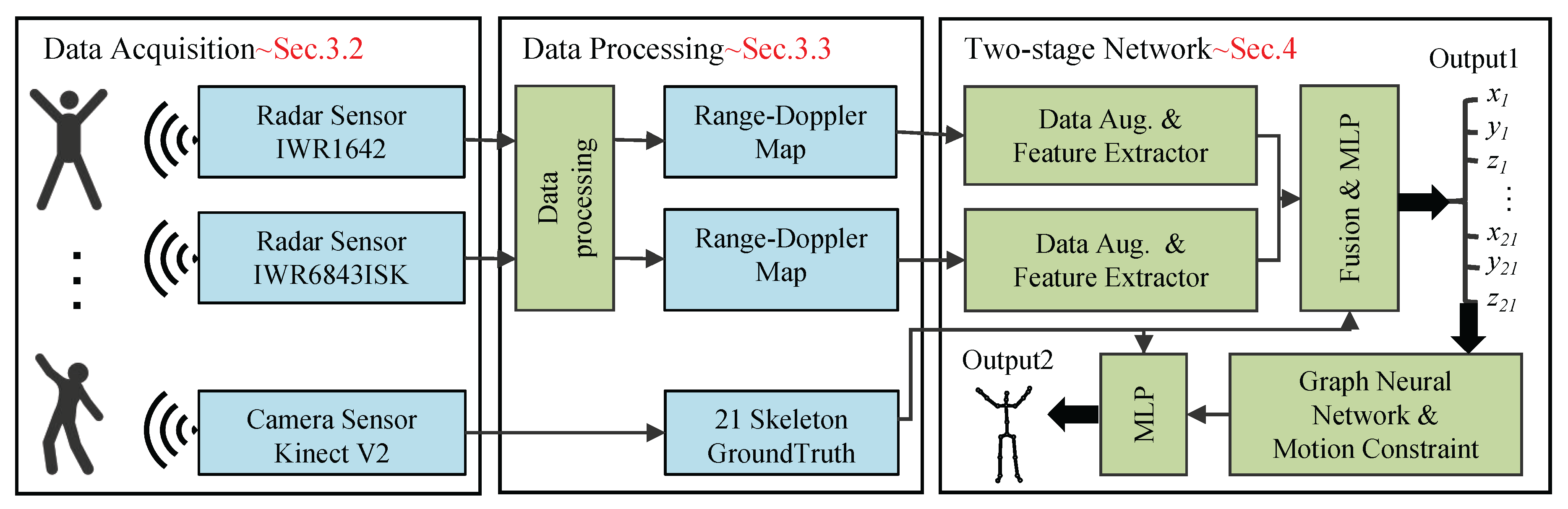
Figure 2.
The data collection and annotation process utilizes the following hardware: (a) the IWR1642BOOST radar for data acquisition, (b) the IWR6843ISK radar for data acquisition, (c) the Kinect V2 camera for data annotation, and (d) The annotation of bone points output by kinect V2.
Figure 2.
The data collection and annotation process utilizes the following hardware: (a) the IWR1642BOOST radar for data acquisition, (b) the IWR6843ISK radar for data acquisition, (c) the Kinect V2 camera for data annotation, and (d) The annotation of bone points output by kinect V2.
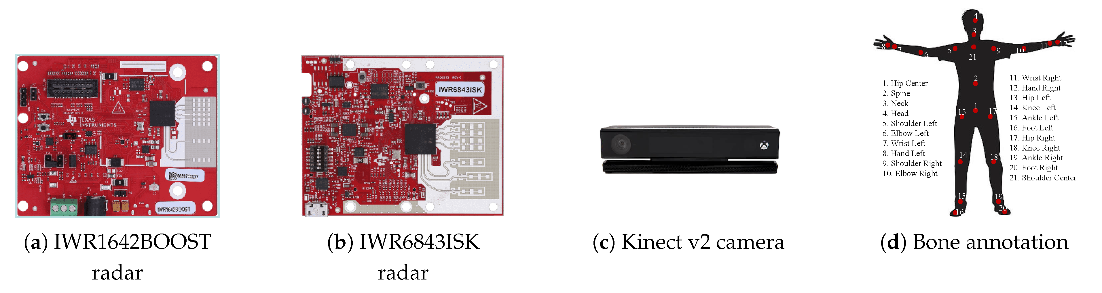
Figure 3.
Radar data processing Pipeline.
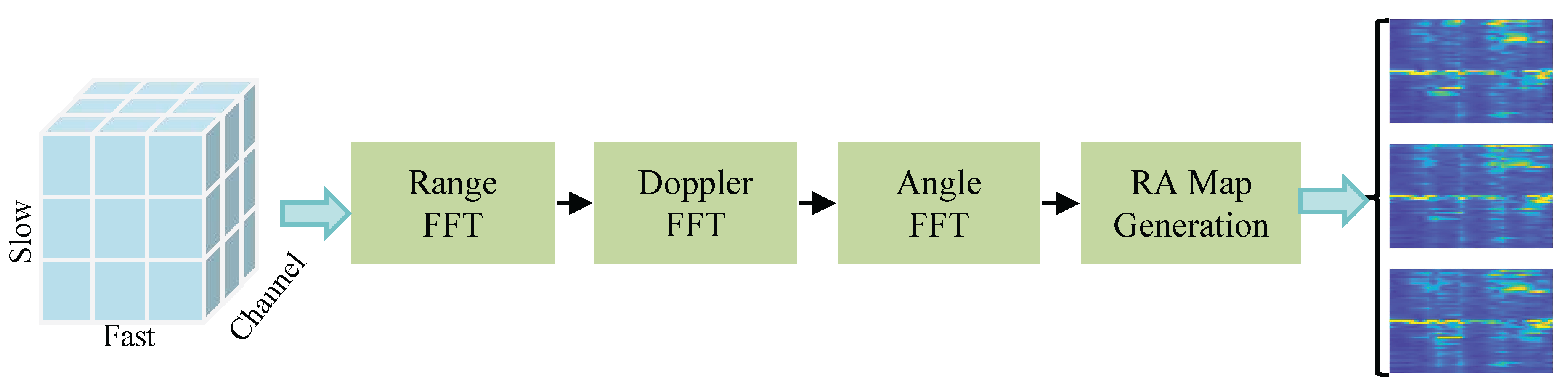
Figure 4.
Key modules of the mm-HSE system. (a) Feature extractor module: used for processing radar input data. (b) Fusion and initial estimation module: used for merging radar input branches and providing preliminary outputs of skeletal point coordinates. (c) Localization Optimizer: used for fine-tuning the skeletal point coordinates.
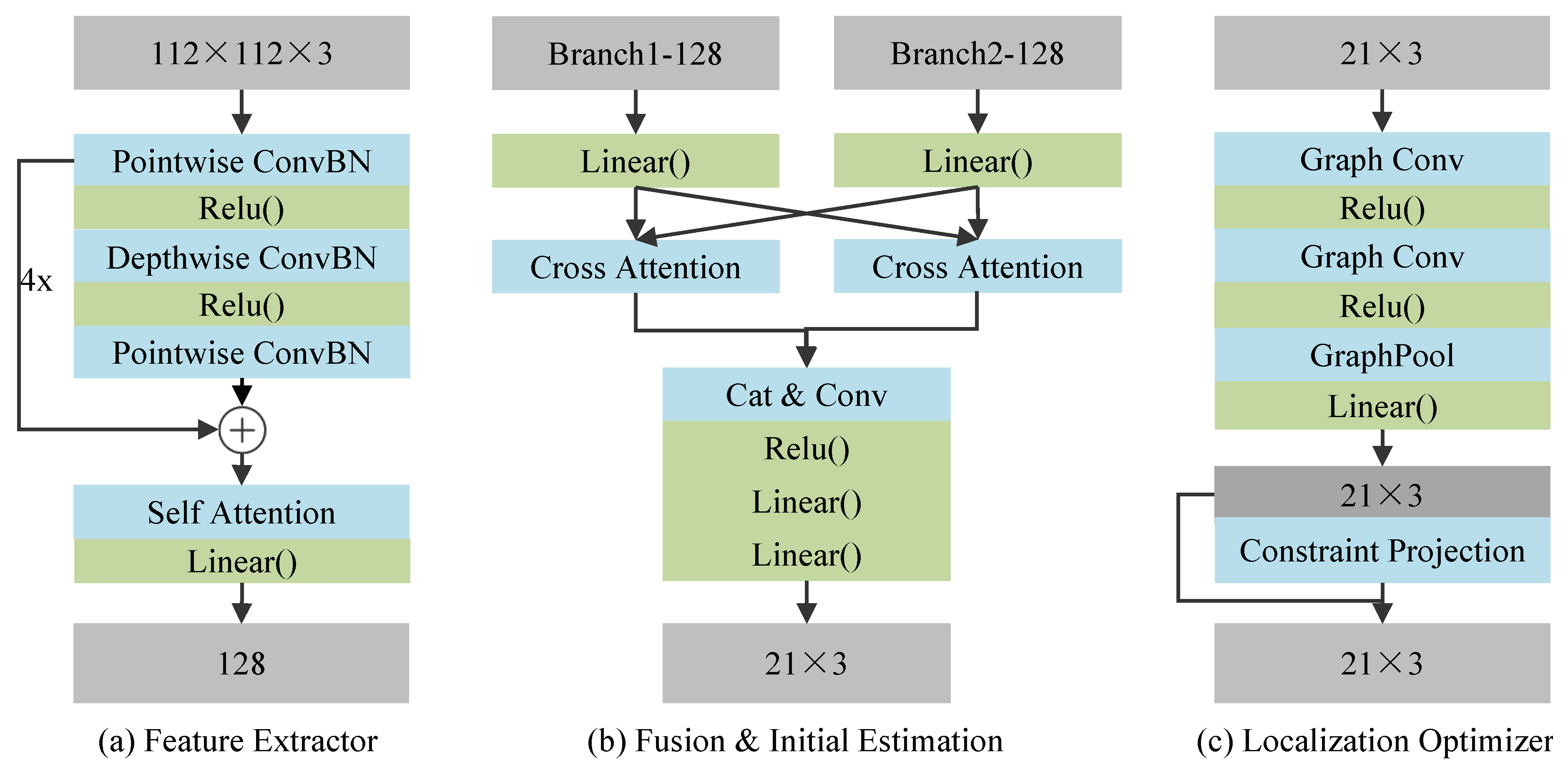
Figure 5.
Verifying the feasibility of using range-angle maps for human skeleton estimation.(a) represents the MAE error, and (b) represents the RMSE error.
Figure 5.
Verifying the feasibility of using range-angle maps for human skeleton estimation.(a) represents the MAE error, and (b) represents the RMSE error.
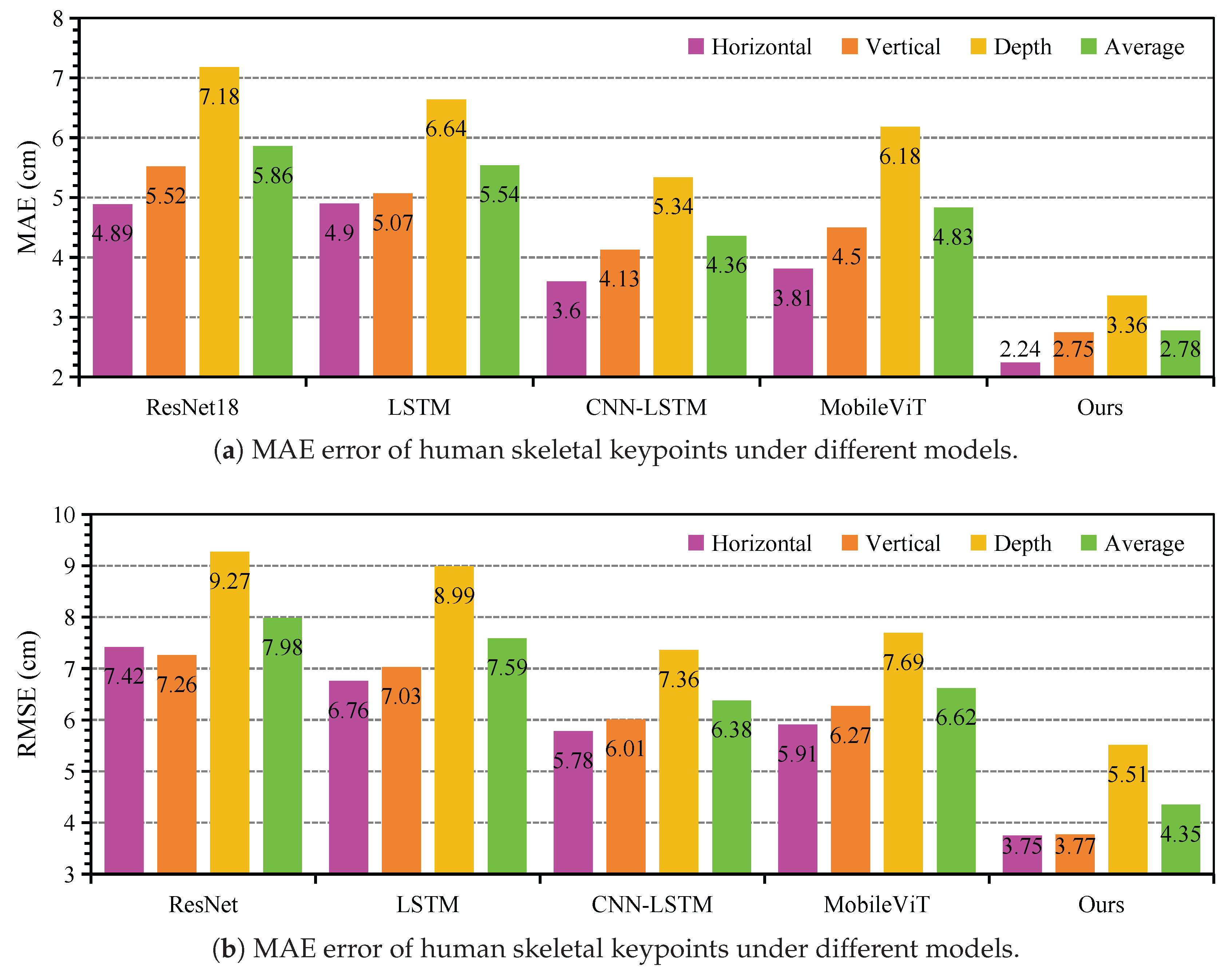
Figure 6.
MAE and RMSE errors for the 21 skeletal keypoints under the mm-HSE system. (a) represents the MAE error, and (b) represents the RMSE error.
Figure 6.
MAE and RMSE errors for the 21 skeletal keypoints under the mm-HSE system. (a) represents the MAE error, and (b) represents the RMSE error.
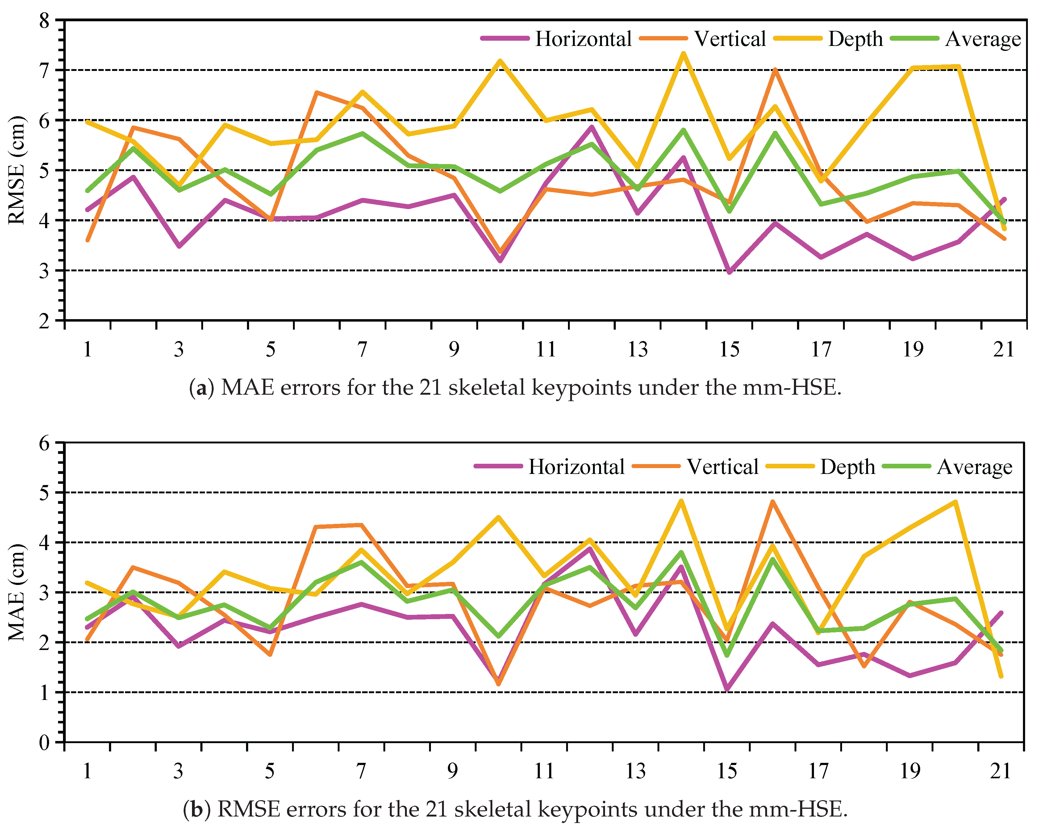
Figure 7.
Estimation performance of the mm-HSE system in cross-domain and cross-user scenarios. "CD" represents cross-domain, and "CU" represents cross-user. (a) represents the MAE error for cross-domain and cross-user, and (b) represents the RMSE error for cross-domain and cross-user.
Figure 7.
Estimation performance of the mm-HSE system in cross-domain and cross-user scenarios. "CD" represents cross-domain, and "CU" represents cross-user. (a) represents the MAE error for cross-domain and cross-user, and (b) represents the RMSE error for cross-domain and cross-user.
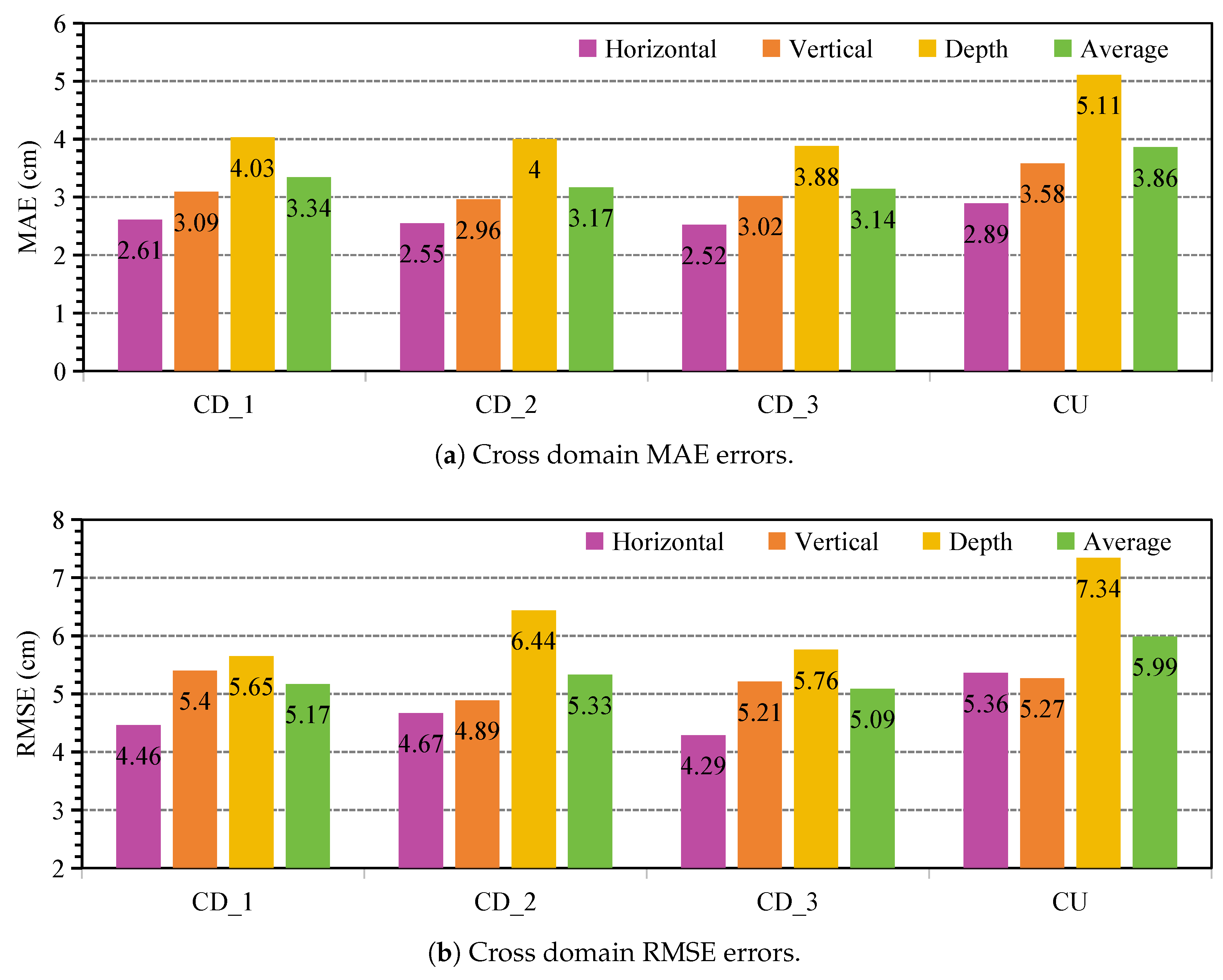
Figure 8.
Comparison of coarse estimation and optimized estimation for the 21 skeletal keypoints. The top row represents the action "stand", and the bottom row represents the action "waveing".
Figure 8.
Comparison of coarse estimation and optimized estimation for the 21 skeletal keypoints. The top row represents the action "stand", and the bottom row represents the action "waveing".
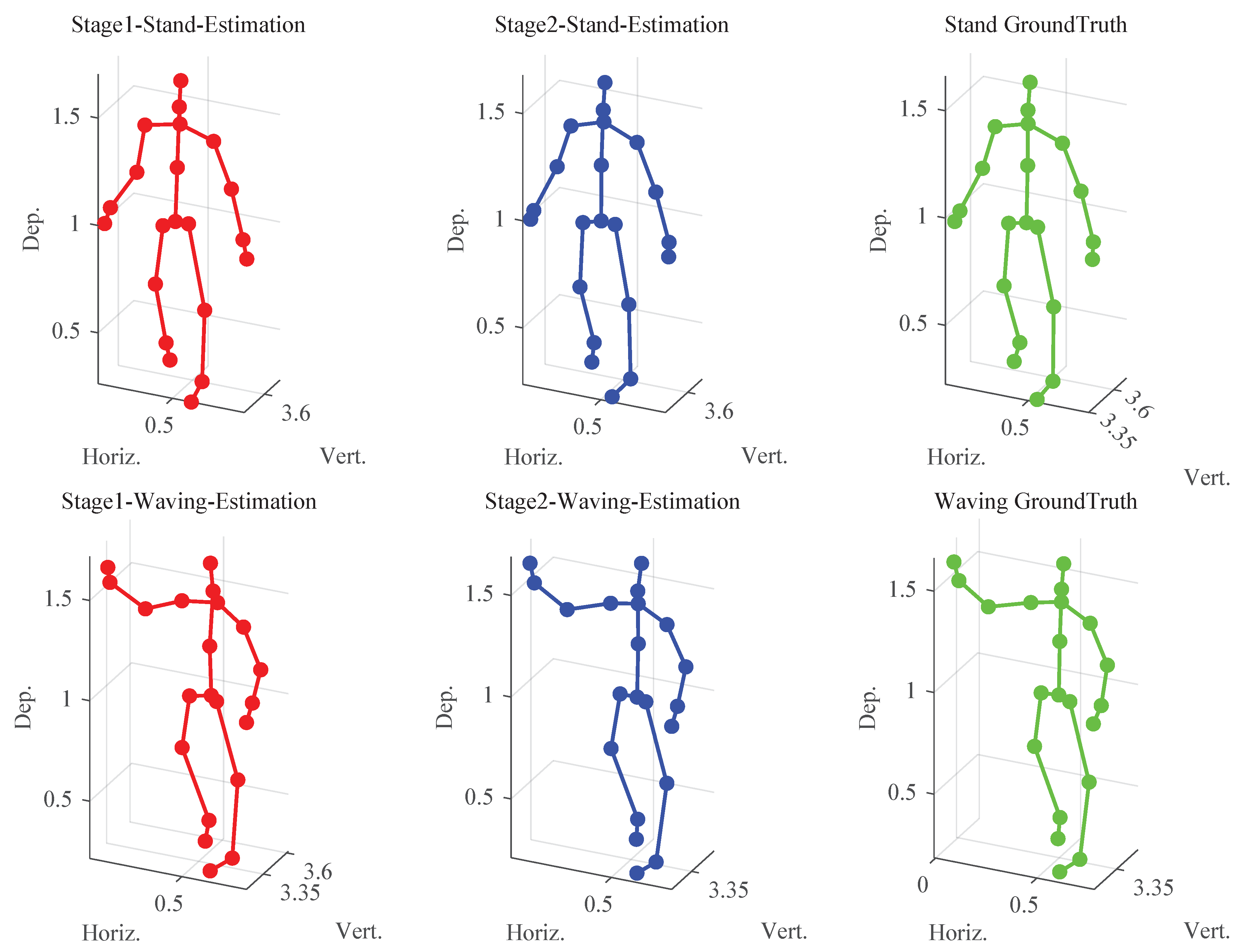
Figure 9.
The impact of historical frames on the mm-HSE system. (a) represents the experimental MAE error of historical frames, and (b) represents the experimental RMSE error of historical frames.
Figure 9.
The impact of historical frames on the mm-HSE system. (a) represents the experimental MAE error of historical frames, and (b) represents the experimental RMSE error of historical frames.
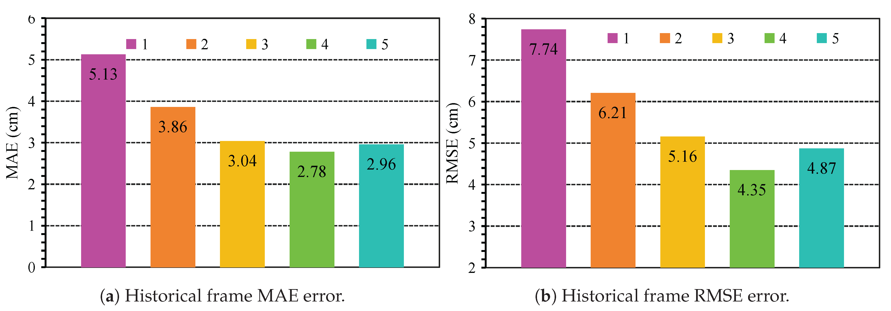
Figure 10.
The impact of fusion weight w on the mm-HSE system. (a) represents the experimental MAE error of fusion weight, and (b) represents the experimental RMSE error of fusion weight.
Figure 10.
The impact of fusion weight w on the mm-HSE system. (a) represents the experimental MAE error of fusion weight, and (b) represents the experimental RMSE error of fusion weight.
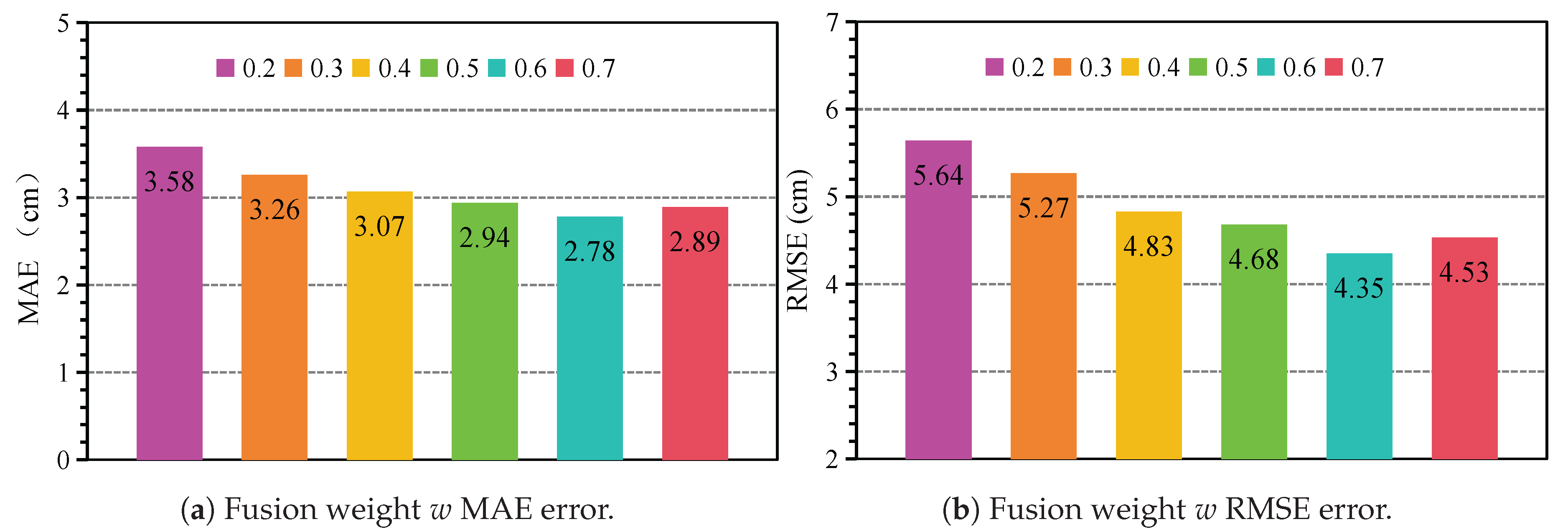
Figure 11.
The impact of attention heads on the mm-HSE system. (a) represents the experimental MAE error of attention heads, and (b) represents the experimental RMSE error of attention heads.
Figure 11.
The impact of attention heads on the mm-HSE system. (a) represents the experimental MAE error of attention heads, and (b) represents the experimental RMSE error of attention heads.
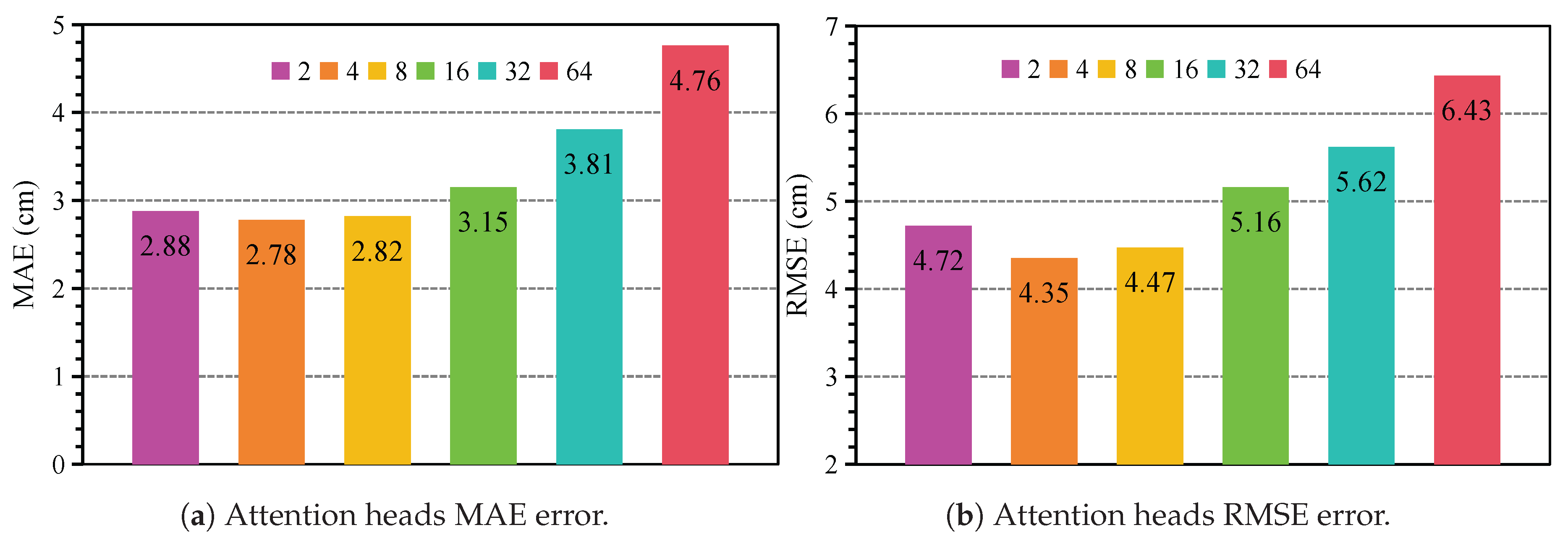

Table 1.
Dual Millimeter-Wave Radar Configuration Parameters
| Symbol | Parameter | IWR1642BOOST | IWR6843ISK |
|---|---|---|---|
| Starting Frequency | 77GHz | 60GHz | |
| B | Effective Bandwidth | 3.001GHz | 3.001GHz |
| Number of TX Antennas | 2 | 3 | |
| Number of RX Antennas | 4 | 4 | |
| Number of Samples per Chirp | 256 | 256 | |
| Number of Chirps per Frame | 32 | 32 | |
| Frame Period | 50ms | 50ms |
Table 2.
Experimental results of related work based on MAE evaluation index.
| Model | Data Representation | Training Set | Test Set | MAE (cm) | |||
|---|---|---|---|---|---|---|---|
| Horiz. | Vert. | Depth | Avg. | ||||
| RF-Pose3D[21] | Heatmap | 127080 | 423360 | 4.9 | 4.0 | 4.2 | 4.37 |
| RPM[22] | Heatmap | 278480 | 69620 | – | – | – | 5.71 |
| mmPose[20] | RGB Image | 32000 | 1700 | 7.5 | 2.7 | 3.2 | 4.47 |
| HuPR[23] | VRADE Heatmap | 115800 | 12600 | – | – | – | 6.82 |
| mm-HSE | Heatmap | 27000 | 3000 | 2.24 | 2.75 | 3.36 | 2.78 |
Table 3.
Ablation study on the effects of different components.
| Data Aug | Stage1 | Fusion | Stage2 | MAE (cm) | RMSE (cm) |
|---|---|---|---|---|---|
| ✓ | 7.34 | 9.86 | |||
| ✓ | ✓ | 5.86 | 8.04 | ||
| ✓ | ✓ | ✓ | 4.62 | 7.19 | |
| ✓ | ✓ | ✓ | 3.84 | 5.83 | |
| ✓ | ✓ | ✓ | ✓ | 2.78 | 4.35 |
Disclaimer/Publisher’s Note: The statements, opinions and data contained in all publications are solely those of the individual author(s) and contributor(s) and not of MDPI and/or the editor(s). MDPI and/or the editor(s) disclaim responsibility for any injury to people or property resulting from any ideas, methods, instructions or products referred to in the content. |
© 2025 by the authors. Licensee MDPI, Basel, Switzerland. This article is an open access article distributed under the terms and conditions of the Creative Commons Attribution (CC BY) license (http://creativecommons.org/licenses/by/4.0/).
Copyright: This open access article is published under a Creative Commons CC BY 4.0 license, which permit the free download, distribution, and reuse, provided that the author and preprint are cited in any reuse.


