Submitted:
16 June 2025
Posted:
19 June 2025
You are already at the latest version
Abstract
Introduction
Nervus hypoglossus stimulation implants are a well-known second-line option for the treatment of obstructive sleep apnea (OSA). Similar to other implants, postoperative radiological positional evaluation serves as a quality control measure for the surgical procedure and as a reference point for future adjustments. Furthermore, the impact of artifacts on the visual assessment of the adjacent structures might be of clinical importance. This study aimed to evaluate postoperative positional implant control and CT-generated artifacts of a bilateral hypoglossal nerve stimulation device.
Material and methods
We retrospectively evaluated postoperative radiological imaging of 9 patients on the first day after implantation of a bilateral nervus hypoglossus stimulation device. A variety of radiological imaging procedures were utilized: 8 CT scans (in sagittal and axial planes) and 9 X-ray examinations were conducted. Eight patients (89%) received postoperative X-ray and CT scans, and one patient (11%) received postoperative X-ray control only. Radiological imaging was analysed regarding the position of the implant, anatomy, and artifacts. The age range of patients varied from 59 to 87 years (mean, 68.9 years; SD, 8.6 years). Preoperative Apnoe-Hypopnoea Index (AHI) varied from 16.5 to 64 (mean 40.1) and Body Mass Index (BMI) ranged from 25 to 34 kg/m2 (mean 29.2 kg/m2).
Results
Evaluation of X-ray images did not reveal artifacts that affected the diagnostic accuracy of postoperative position control. In contrast, CT images showed artifacts in the coronal, sagittal, and axial planes, making radiological assessment more difficult. We observed a high variation of device position without any effect on functionality. Paddle asymmetry was found in 78% of cases (7 out of 9).
Conclusion
Postoperative radiologic monitoring after implantation of a bilateral hypoglossal nerve stimulator is recommended. A high variation of device position could be found. The variability in implant position observed in our study group does not affect the implant's functionality. CT artifacts need to be considered.
Keywords:
OSAS
; hypoglossus nerve stimulation
; radiology
; HGNS
Introduction
Obstructive sleep apnea (OSA) is a prevalent sleeping disorder characterized by partial or total obstruction of the upper airway due to a decrease in pharyngeal muscle activity during sleep [1]. As the first-The line treatment therapy, positive airway pressure (PAP), is established for moderate to severeOSA patients. As PAP therapy underlies a low acceptance rate, hypoglossal nerve stimulation (HGNS) has emerged as an effective and equivalent second-line treatment for patients with moderate to severe OSA with poor adherence to positive airway pressure (PAP) therapy [2,3,4,5]. A breathing-synchronized unilateral hypoglossal nerve stimulation device (uniHGNS, Inspire Medical Systems (United States) received FDA approval in 2014. A bilateral non-breathing-The synchronized HGNS (biHGNS) device represents a further approach to OSA treatment. The Genio (Nyxoah SA, Belgium) The system received its European CE Mark in 2019 and recently submitted the fourth and final module of its premarket approval application to the FDA. The Genio is used in adult patients to treat moderate to severe OSA who have not tolerated or refused PAP therapy, or in whom this therapy was not effective. The system involves the implantation of a single device that stimulates the hypoglossal nerve bilaterally, which in turn activates the tongue muscles to maintain an open airway during sleep. The system consists of a stimulator that is implanted during a minimally invasive procedure and positioned over the genioglossus muscle with the electrodes aligned bilaterally to both the left and right. The electrodes are aligned with the left and right branches of the hypoglossal nerve. The stimulation of the hypoglossal nerve leads to contraction of the tongue muscle, which keeps the airways open. Postoperative radiological monitoring of intracorporeal implants is part of the clinical standard and has three functions across all implants: 1. Objectification of what has been done. 2. Objectification of how it was performed. 3. Establishing a reference value for postoperative complications. In the field of ENT medicine, these principles can be found in plate treatment for midface fractures or the course of cochlear implant treatment. Here, the position of the electrodes is checked postoperatively. Postoperative position control is also recommended in the course of biHGNS. This postoperative assessment is a reference point for possible future stimulation changes. It can be assumed that the anatomical situation and the surgical variability influence the position of the implant. The presence of HGNS implants is assumed to generate radiological artifacts when patients undergo diagnostic imaging. These artifacts primarily affect modalities like magnetic resonance imaging (MRI) and computed tomography (CT), where interference from metallic components of the device may distort the resulting images. Physical effects causing metal artifacts depend on the composition and geometry of metal implants [6]. Radiological parameters of image acquisition and image reconstruction must also be taken into account [7]. Metal artifacts lead to undesirable distortions like streaks and shadows in the reconstructed images, which can obscure critical anatomical details and make radiological interpretation more difficult [8].
Radiological assessment of a unilateral HGNS device with a focus on therapeutic outcome and device position monitoring has been described recently [9]. Therapeutic outcome of biHGNS implants are well-documented, but literature addressing radiological assessment of biHGNS is to date not available. This retrospective study aimed to evaluate the postoperative variability of the submental-located biHGNS implant position by X-ray and to observe CT artifacts.
Material and Methods:
Inclusion criteria were (i) age ≥ 18 years; (ii) postoperative radiological examinations (CT/X-ray) after bilateral HGNS implantation. Data were collected retrospectively from 9 patients who underwent implantation of a bilateral nervus hypoglossus stimulation device (Genio Implant, Nyxoah, Mont-Saint-Guibert, Belgium) between January 2024 and January 2025.
Patient characteristics
A total of 9 patients underwent biHGNS surgery. Among these patients, all were male. The age range of patients varied from 59 to 87 years (mean 68.9 years; SD 8.6 years). The preoperative Apnoea-Hypopnoea Index (AHI) ranged from 16.5 to 64 (mean 40.1), indicating severe obstructive sleep apnea in our study group according to the AHI severity classification. The mean Body Mass Index (BMI) was 29.2 kg/m2 (25-34 kg/m2), indicating overweight to obesity according to BMI categories. All patients (100%) had dental implants. The known eligibility criteria for biHGNS operation were met by all patients.
An implantable bilateral hypoglossal nerve stimulation system
The implantable stimulator (IS) is a sterile, small, disposable implant that stimulates both left and right branches of the hypoglossal nerve (see Figure 1).
The body of the IS consists of a current-receiving antenna, an electrical circuit, and two lateral legs with two paddle electrodes. Materials with tissue contact: Polyp (p-xylylene) polymer - ParyleneC, coating of the implant. Platinum the electrodes of the implant. MED 4840/4860 - silicone rubber.
Physical description: Length (at the upper plate): 27,5 mm. Inner width (between the paddles in parallel position): 24,3 mm. Height: 20,0 mm. Maximum thickness: 3,2 mm. Total volume: 2,2 cm3. Total weight: 3 g.
Surgery
All patients underwent surgery under general anesthesia. The biHGNS is implanted during a minimally invasive surgical procedure through a small incision under the chin. A nerve monitoring-guided selective hypoglossal nerve stimulation was performed using a nerve integrity monitoring system (NIM 3.0; Medtronic) [10]. After NIM-guided separation of the protrusion and retrusion nerve fibers, paddle electrodes of the implantable stimulator were positioned on each side, and the implantable stimulator was sutured on both sides of the genioglossus muscle belly. Using an external stimulator intraoperatively, the correct paddle electrode position on the protruding nerve fibres of the genioglossus and tongue movements was visualized. The incision was closed with skin sutures after a satisfactory response was achieved. In all patients, no adverse events were reported during and after implantation. Surgery was performed successfully, and perioperative stimulation tests were sufficient.
Radiological Imaging
We retrospectively analyzed radiological imaging as part of postoperative position control. To determine the postoperative position of the biHGNS implant, conventional X-ray images in two planes (sagittal and anterior-posterior projection) and/or CT scans in three planes (coronal, sagittal, and axial planes) were performed. A variety of radiological imaging procedures were utilized: 8 CT scans (in sagittal and axial planes) and 9 X-ray examinations were conducted. Eight patients (89%) received postoperative X-ray and CT scans, and one patient (11%) received postoperative X-ray control only.
All patients were scanned in the supine position. A multislice computed tomography (CT) system (Aquilion ONE, Canon Medical Systems, Otawara, Japan) was used for scanning. The single-energy metal artifact reduction algorithm (SEMAR) was applied to reduce metal artifacts from electrodes [11]. SEMAR algorithms employ mathematical techniques to identify and model regions affected by metal artifacts.
The following CT scan parameters were applied: maximum tube current, 260 mA; tube voltage, 120 kV.
X-ray examinations were performed on Philips DigitalDiagnost C90. The protocol was as follows: DFP 5.73 – 33.78 cGy cm2. Exposure 4-18.
Visual analysis of images was performed using a medical image archive (DeepUnity Diagnost/Review 2.0.2.2, Dedalus S.p.A., Italy).
Anatomical features were measured according to a previous study for a unilateral implant device by Schwab et al. (2018) as follows: mandibular length (in mm), distance mandibula plane-to-hyoid (in mm), distance chin to hyoid (in mm) and distance hyoid to implant (in mm) were measured using a medical image archive both for CT and/or X-ray. Furthermore, the position of the paddle electronics was analyzed in relation to the mandible and hyoid bone, based on previous findings for a unilateral implant device by Steffen et al. (2020).
The implant position was analyzed using digital reference lines to assess symmetrical or asymmetrical alignment of the bilateral paddle electrodes. A vertical midline was drawn through the stimulation antenna. A horizontal reference line at the stimulation antenna base was drawn perpendicular to the vertical midline. Symmetry was defined as equally aligned paddle electrodes on both sides.
Artifacts caused by the implant and/or surrounding pre-existing external materials (e.g., dental implants, dental fillings) and/or soft/bone tissue were analyzed. The degree of metal artifacts severity of the biHGNS implant was assessed as follows: mild (good evaluation of surrounding tissue), moderate (acceptable evaluation of surrounding tissue), and strong (limited evaluation of surrounding tissue).
Results:
Anatomical features were measured as follows (see Figure 2 and Table 1): mean mandibular length was 102.0 mm (86.0 – 122.3). Mean distance from chin to hyoid was 61.2 mm (47.1 – 77.9). Mean distance mandibula plane-to-hyoid was 35.1 mm (20.3 – 55.3).
There was a variability of paddle electrode position. Visual radiological assessment and measurements of the paddle electrode position on the left and right sides revealed symmetrical positions in 2 out of 9 cases (22%) and asymmetrical positions in 7 out of 9 cases (78%) (see Table 1, Figure 3 and Figure 4).
Mean distance of the hyoid bone to the paddle electrode of the right side was 15.3 mm (7.9-18.8). Mean distance of the hyoid bone to the paddle electrode of the left side was 18.9 mm (6.6-32.9).
Evaluation of the hyoid bone to stimulation antenna angle (in °) revealed a mean angle of 52.0° (19.0 – 73.8) (see Figure 5).
The paddle electrode positioning was located proximal to the mandible in 9 out of 9 cases (100%) (see Figure 6).
The paddle electrode positioning, relative to the anterior margin of the hyoid bone, was proximal in 6 out of 9 cases (67%) and distal in 3 out of 9 cases (33%) (see Figure 7).
Evaluation of 9 X-ray images did not reveal artifacts in the sagittal and coronal views that might affect the diagnostic accuracy of postoperative position control. In all 9 cases (100%), examination could be performed without any image distortions.
CT images showed artifacts in all 8 cases (100%). Here, a visual artifact graduation was applied according to recognized artifact intensity (see Figure 8 and Figure 9).
Five out of eight cases (63%) exhibited moderate artifacts, with an acceptable evaluation of the surrounding tissue. Three out of eight cases (37%) presented with strong artifacts, which limited the review of surrounding tissue and resulted in significant limitations in postoperative CT image assessment.
In all cases, a regular protrusion of the tongue was observed both intraoperatively and postoperatively, regardless of radiological electrode position.
Discussion:
Postoperative radiological positional control is the standard of care for many implants used in the otolaryngological field (e.g., cochlear implant, plates, etc.).
For biHGNS, it acts as a reference point in cases of a complex postoperative adjustment process or malfunction caused by a dislocation.
In case of postoperative hematoma, seroma, or wound infections, radiological monitoring of the implant position can deliver essential insights into the submental region. Due to the age and secondary diseases of patients with obstructive sleep apnea, the detection and characterization of tumors, including primary tumors of the head and neck region, is of particular interest.
Despite the application of a single-energy metal artifact reduction algorithm (SEMAR) to reduce artifacts, radiological examinations are still affected by artifacts caused by dental implants or metal components of the implantable hypoglossal nerve stimulator. SEMAR cannot eliminate all artifacts, particularly if the metal object is located in a challenging area, such as the floor of the mouth, with anatomical relationships to bones, soft tissue, and dental fillings.
We used bone structures as landmarks for controlling the radiological implant position. We identified variable anatomical features (mandibular length, distance from the mandibular plane to the hyoid bone, distance from the chin to the hyoid bone, and distance from the hyoid bone to the implant position) based on individual anatomical differences.
Position control of paddle electronics symmetry was evaluated based on the assumption that an asymmetrical electrode position leads to insufficient nerve stimulation and tongue movement. We observed a high variability of implant position without any effect on the functionality of biHGNS.
Contrary to the hypothesis that a proximal electrode position is unfavorable and that an electrode position closer to the mandible reduces the risk of retraction fiber stimulation, no direct conclusions could be drawn about the postoperative stimulation of the nervus hypoglossus in our study group. These results align with those of Steffen et al. (2020). Radiological imaging can therefore be used to determine whether the electrode is in a proximal or distal position. Due to the individual and complex anatomy of the nerve, it is not possible to make a reliable statement postoperatively as to whether one of the desired tongue movements can be expected.
In the present study, postoperative assessment of X-ray images did not reveal artifacts in the sagittal and coronal views that might affect the diagnostic evaluation. X-rays provide 2D images that are less detailed and more challenging to interpret in cases of complex diagnostic requirements involving soft tissue. It can be difficult to distinguish structures that overlap on an X-ray image, which can lead to misinterpretations. Although the radiation dose is relatively low compared to CT scans, there is still radiation exposure.
Typically, CT scans are more advanced than X-rays in identifying detailed and complex conditions. CT scans provide high-resolution, cross-sectional images of the body, enabling more detailed views of bones and soft tissue than X-rays.
But artifacts caused by metal parts are a fairly common problem in CT imaging. CT images of our study group showed artifacts of varying intensity, ranging from moderate to strong, in all cases, which affected the visual assessment of the previously mentioned anatomical region. CT scans revealed artifacts in the coronal, sagittal, and axial planes, which made radiological assessment more challenging.
Artifacts in CT scans are manageable, but require CT scans in at least two planes to ensure optimal assessment of the submental region, the mouth base, and the base of the tongue.
Nevertheless, radiological CT assessment is restricted after biHGNS implantation due to artifacts influenced by factors such as individual anatomy measures, previous implants (e.g., dental implants, dental fillings), and the position of the biHGNS implant device.
However, the patient's exposure to radiation must be weighed up against the potential gain in knowledge. Besides the disadvantage of higher radiation exposure, CT imaging creates higher costs. A postoperative X-ray can nevertheless be recommended to document the implant position and rule out implant displacement.
But knowledge about the number of artifacts is of importance since an overlapping group of patients with biHGNS and head and neck cancer can be assumed in the future.
A limitation of the study is that, with the current biHGNS device, differentiation between unilateral and bilateral stimulation is not electrophysiologically possible without the use of anesthesia.
Conclusion
Postoperative radiologic monitoring after implantation of a bilateral hypoglossal nerve stimulator is strongly recommended. A high variation of device position could be found. The variability in implant position observed in our study group does not affect the implant's functionality. CT artifacts need to be recommended.
Author contributions
KA: writing, idea, data collection, statistics, final approval. RA: analysis, correction, final approval. KR: analysis, correction, final approval. GHB: analysis, correction, final approval. AN: analysis, correction, final approval. SLU: analysis, correction, final approval. TI: writing, design, idea, data collection, final approval, accountable for all aspects.
Ethical approval
The study is conducted by the guidelines for human studies and adheres to the World Medical Association Declaration of Helsinki. The study was reviewed and positively evaluated by the Ethical Commission of the Wilhelms Universität Münster (2024-809 fS; 25.11.2024). All patients provided written consent for their participation in the study.
Availability of data and materials
The data used to support this study’s findings are available from the corresponding author upon request.
Request.
Competing interest
The authors declare that they have no competing interests.
Conflict of Interests / Financial Disclosure
none
References
- Strollo PJ, Rogers RM. Obstructive sleep apnea. N Engl J Med 1996;334:99–104. [CrossRef]
- Schoch OD, Baty F, Niedermann J, Rüdiger JJ, Brutsche MH (2014) Baseline predictors of adherence to positive airway pressure therapy for sleep apnea: a 10-year single-center observational cohort study. Respiration 87(2):121–128. [CrossRef]
- McEvoy RD et al (2016) CPAP for prevention of cardiovascular events in obstructive sleep apnea. N Engl J Med 375(10):919–931. [CrossRef]
- Strollo PJJ et al (2014) Upper-airway stimulation for obstructive sleep apnea. N Engl J Med 370(2):139–149. [CrossRef]
- Hofauer B, Philip P, Wirth M, Knopf A, Heiser C (2017) Effects of upper-airway stimulation on sleep architecture in patients with obstructive sleep apnea. Sleep Breath Schlaf Atm. [CrossRef]
- Katsura M, Sato J, Akahane M, et al. Current and novel techniques for metal artifact reduction at CT: practical guide for radiologists. Radiographics 2018;38:450–61. [CrossRef]
- Lee MJ, Kim S, Lee SA et al (2007) Overcoming artifacts from metallic orthopedic implants at high-field-strength MRimaging and multi-detector CT. Radiographics 27:791–803. [CrossRef]
- Laukamp KR, Zopfs D, Lennartz S, Pennig L, Maintz D, Borggrefe J, Große Hokamp N. Metal artifacts in patients with large dental implants and bridges: combination of metal artifact reduction algorithms and virtual monoenergetic images provides an approach to handle even strongest artifacts. Eur Radiol. 2019 Aug;29(8):4228-4238. [CrossRef] [PubMed]
- Steffen, A., Wozny, A.S., König, I.R. et al. Upper airway stimulation for obstructive sleep apnea—Can radiological position monitoring predict tongue motion one year after implantation?. HNO 68 (Suppl 1), 11–16 (2020). [CrossRef]
- Heiser C, Hofauer B, Lozier L, Woodson BT, Stark T. Nerve monitoring-guided selective hypoglossal nerve stimulation in obstructive sleep apnea patients. Laryngoscope. 2016;126(12):2852-2858. [CrossRef]
- Chang YB, Xu D, Zamyatin AA. Metal artifact reduction algorithm for single energy and dual-energy CT scans. In: Proceedings of the 2012 IEEE Nuclear Science Symposium and Medical Imaging Conference Record (NSS/MIC), Anaheim, California. October 27 to November 3, 2012:3426–29.
Figure 1.
Overview of Genio® system technology. Source: Nyxoah SA, Belgium.
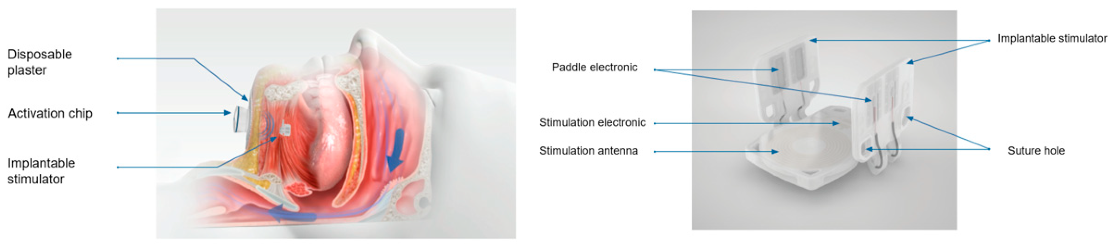
Figure 2.
X-ray (sagittal). Measurement of mandibular length, distance from mandible plane to hyoid, and distance from chin to hyoid bone.
Figure 2.
X-ray (sagittal). Measurement of mandibular length, distance from mandible plane to hyoid, and distance from chin to hyoid bone.
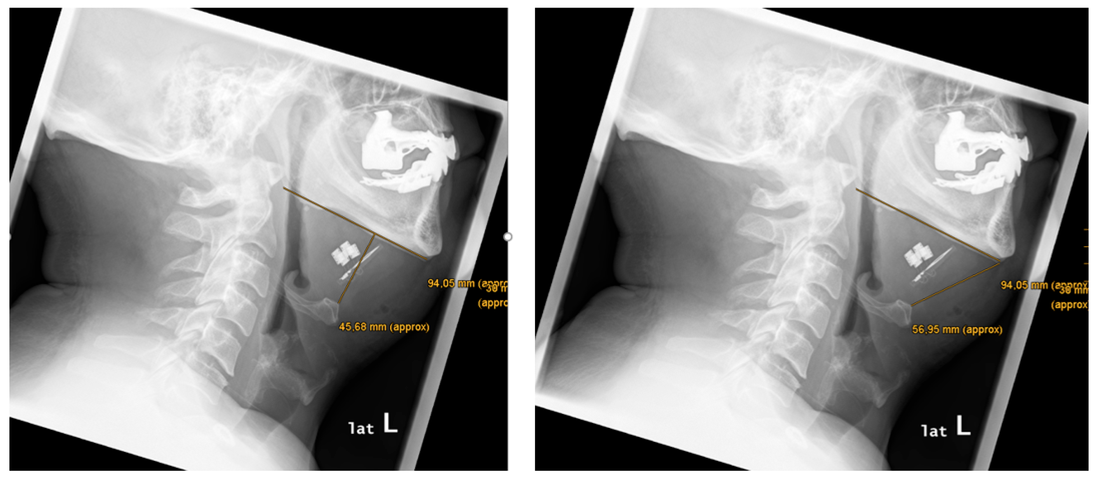
Figure 3.
X-ray (a.p., sagittal). Digital reference lines (blue). Symmetrical alignment of bilateral paddle electrodes.
Figure 3.
X-ray (a.p., sagittal). Digital reference lines (blue). Symmetrical alignment of bilateral paddle electrodes.
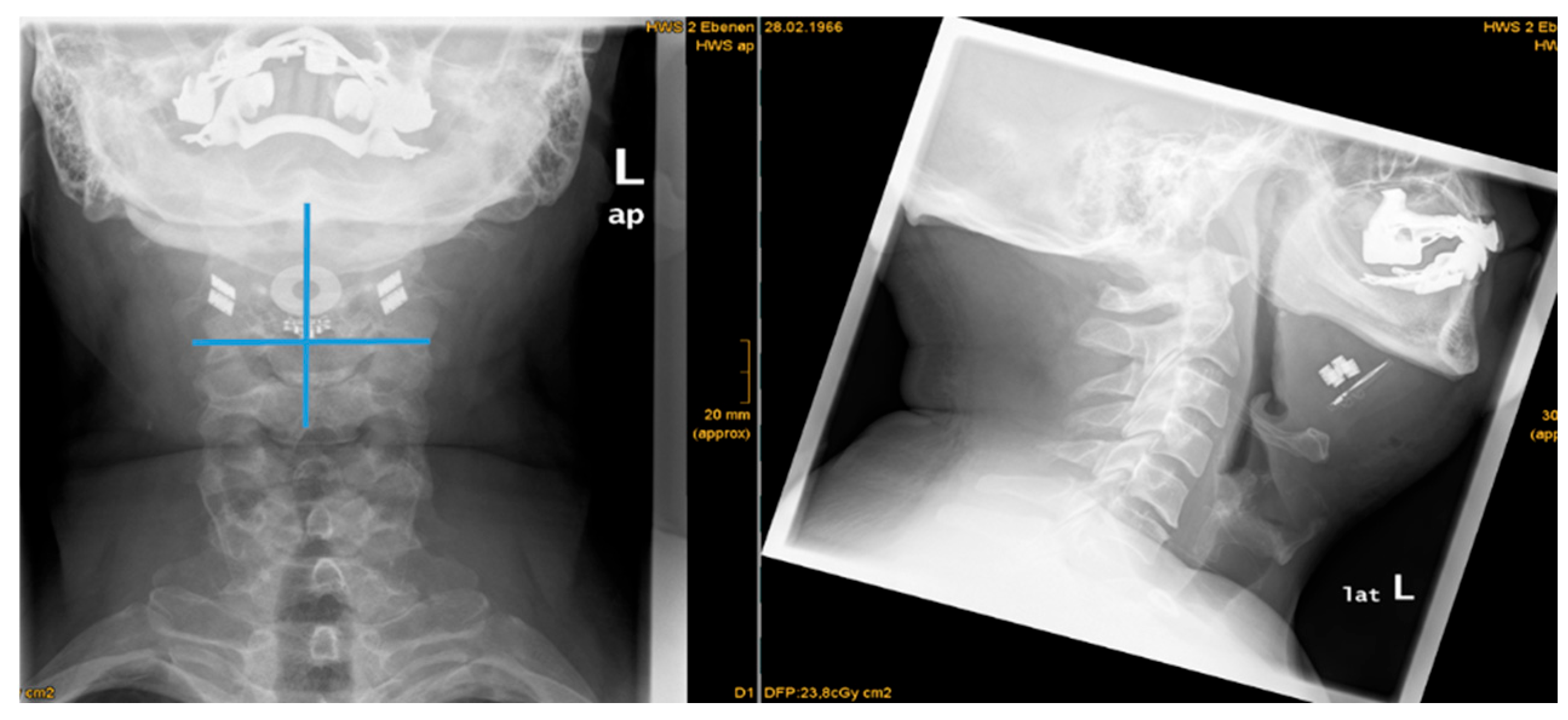
Figure 4.
X-ray(a.p., sagittal). Digital reference lines (blue). Asymmetrical alignment of bilateral paddle electrodes.
Figure 4.
X-ray(a.p., sagittal). Digital reference lines (blue). Asymmetrical alignment of bilateral paddle electrodes.
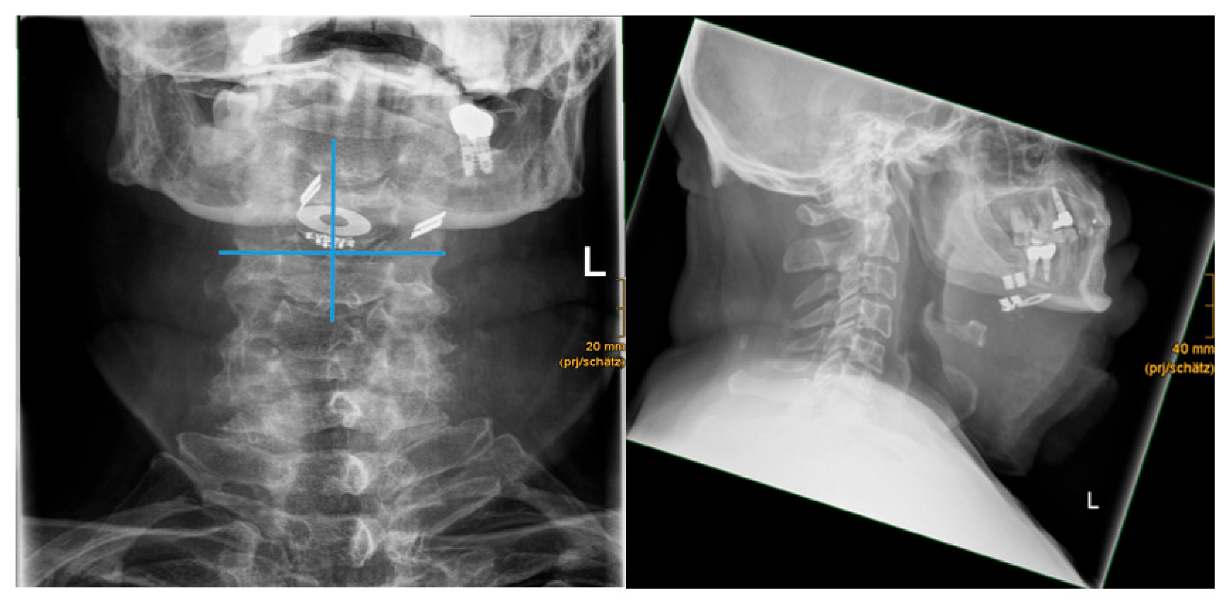
Figure 5.
X-ray (sagittal). Position of paddle electronics and angle of hyoid to implant (in °).
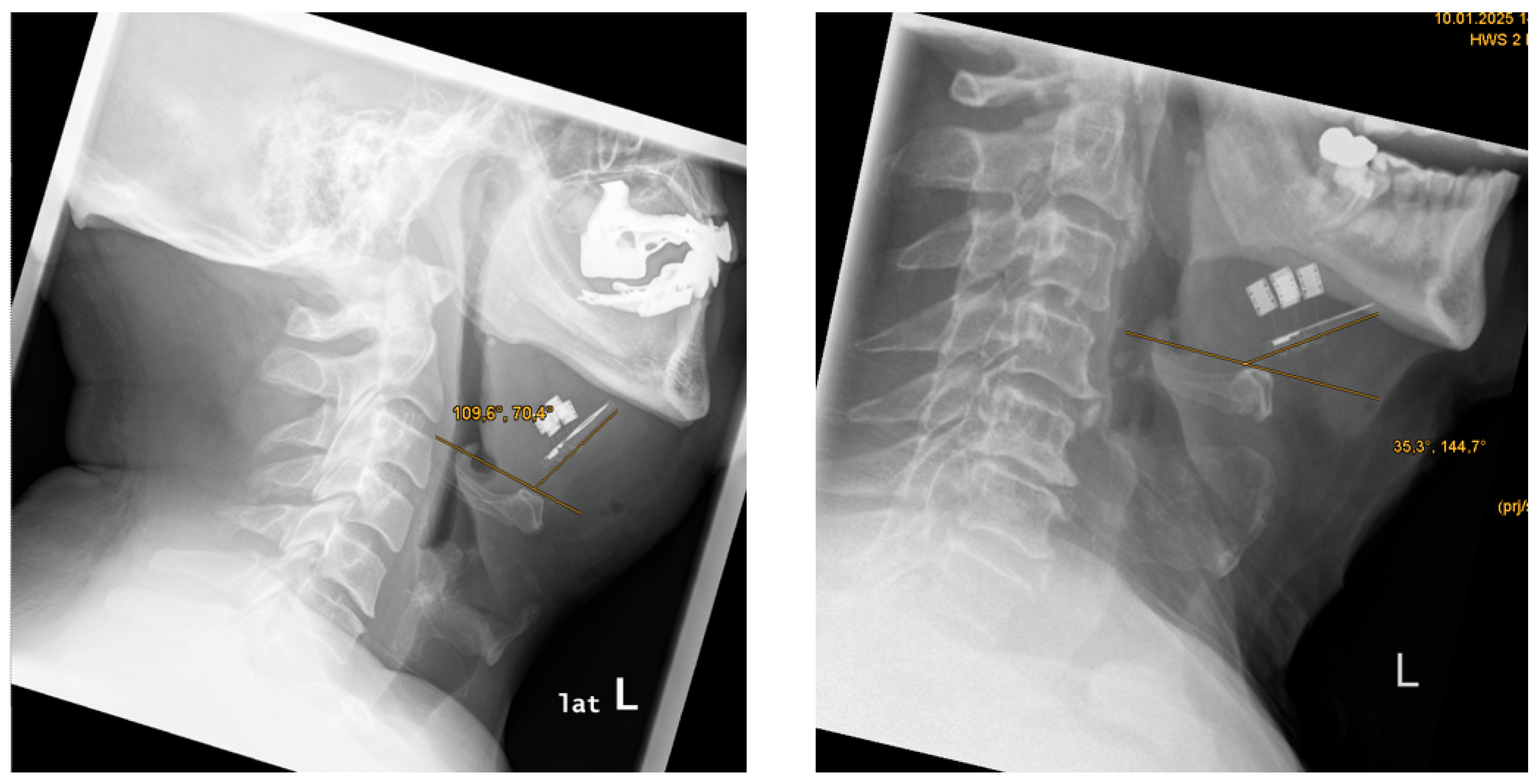
Figure 6.
X-ray (sagittal). Position of paddle electronics about the mandible.
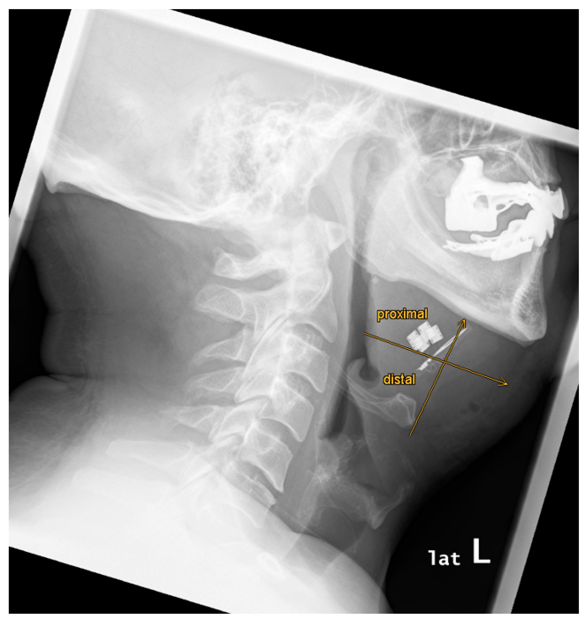
Figure 7.
X-ray (sagittal). Position of paddle electronics about the anterior margin of the hyoid bone.
Figure 7.
X-ray (sagittal). Position of paddle electronics about the anterior margin of the hyoid bone.
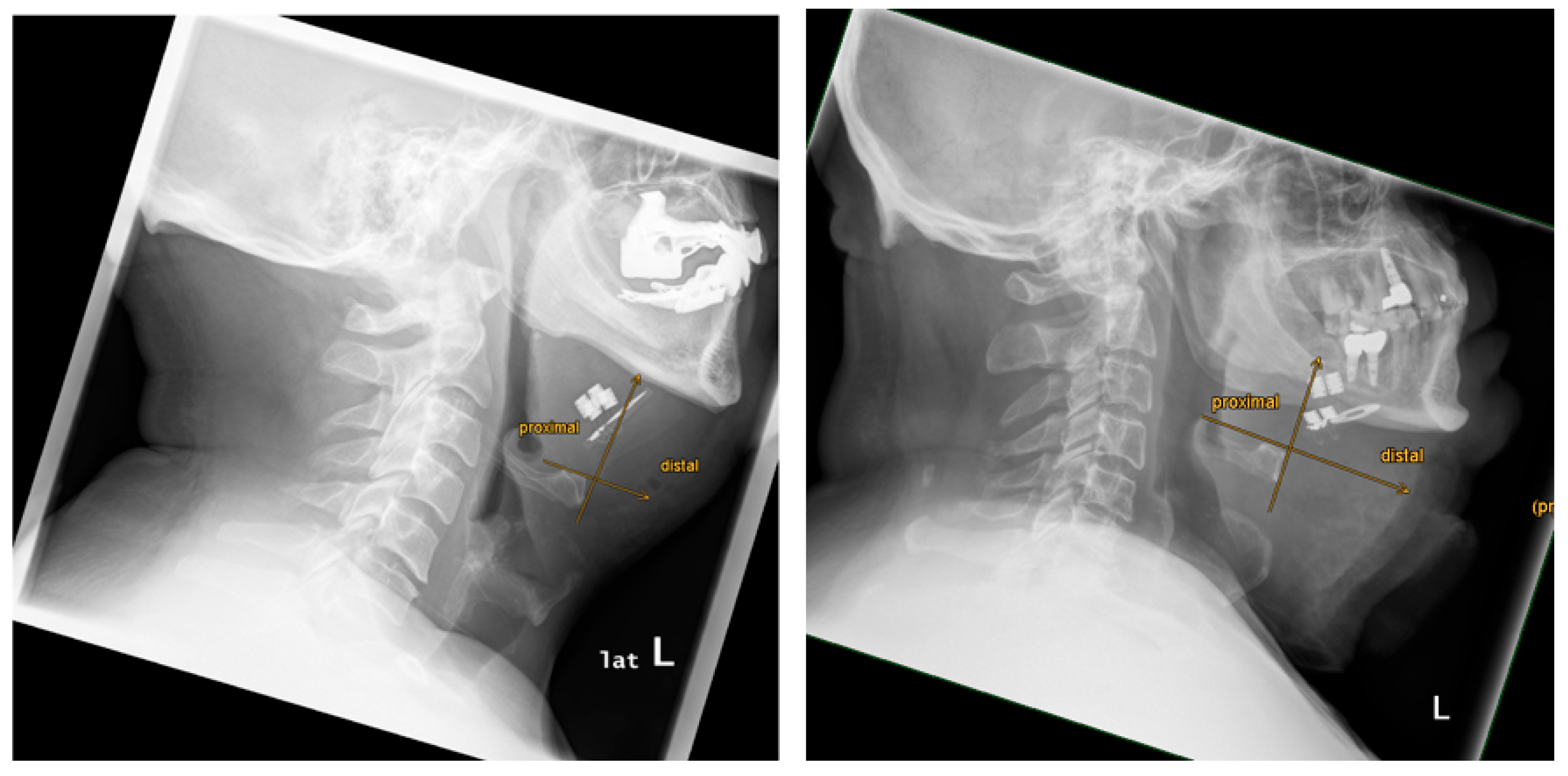
Figure 8.
CT (axial and sagittal planes). biHGNS implant position and strong artifacts.
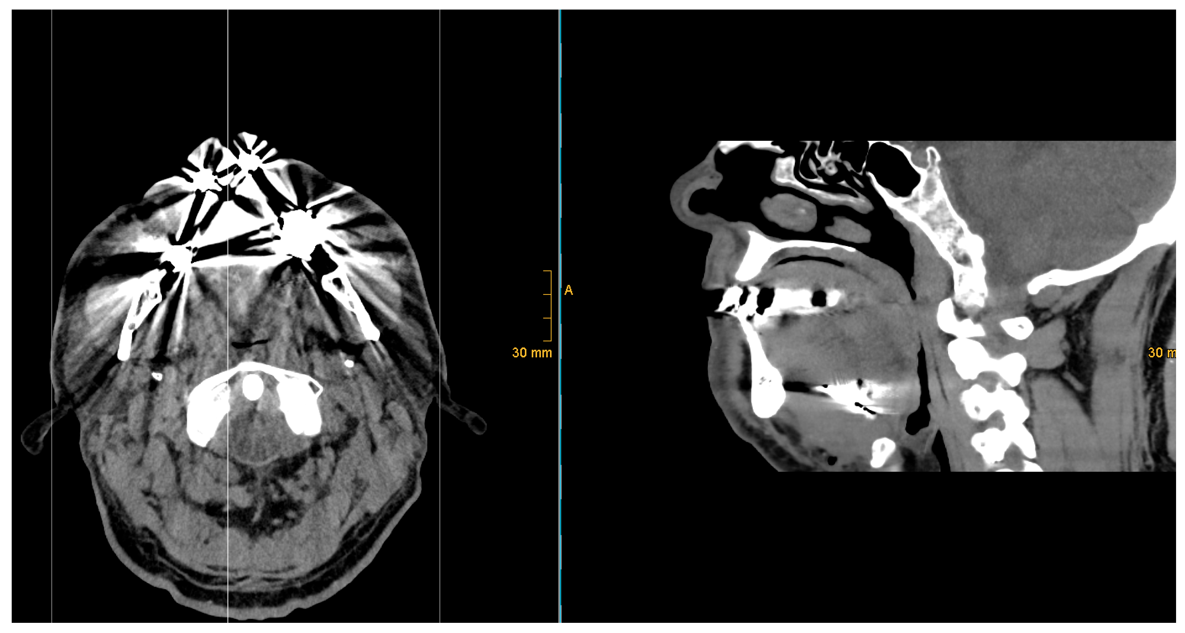
Figure 9.
CT(axial and sagittal planes). biHGNS implant position and moderate artifacts.
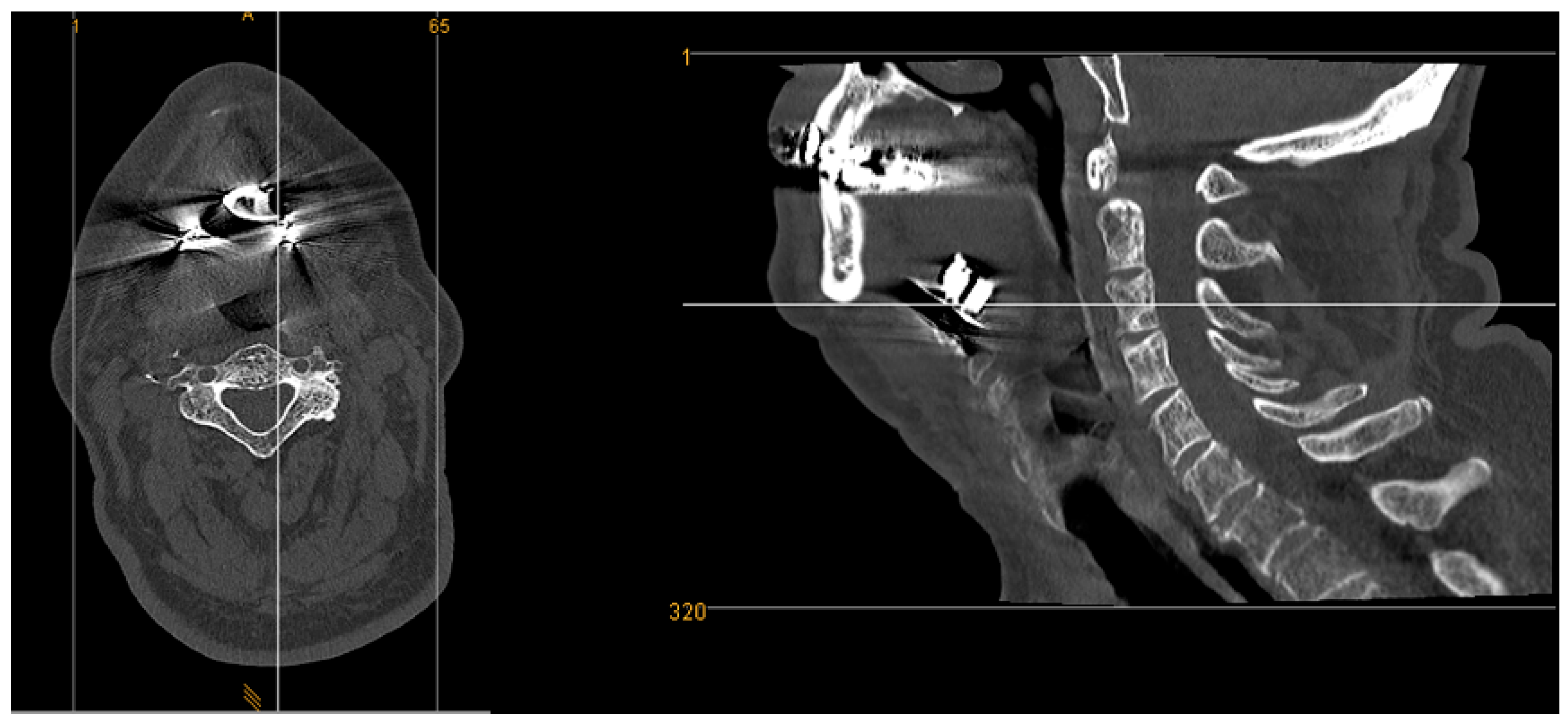

Table 1.
Patient-specific results.
| Patient | AHI | BMI | previous implants (e.g. dental implant) | postoperative CT performed | artifacts CT | artifacts CT severity level | artifacts X-ray | postoperative XRAY performed | mandibular length (in mm) | distance mandibula plane-to-hyoid (in mm) | distance chin to hyoid (in mm) | mean distance hyoid to paddle electrode (in mm) | 1_right side_distance hyoid to paddle electrode (in mm) | 2_left side_distance hyoid to paddle electrode (in mm) | Difference right-left side (in mm) | alignement paddle electrode symmetry/asymmetry | angle hyoid-stimulation antenna (in °) | electrode position proximal/distal to mandible | electrode position proximal/distal to hyoid |
|---|---|---|---|---|---|---|---|---|---|---|---|---|---|---|---|---|---|---|---|
| 1 | 33 | 26 | yes | yes | yes | moderate | no | yes | 87,3 | 28,7 | 56,4 | 15,2 | 7,9 | 22,6 | -14,7 | asymmetry | 64,9 | proximal | proximal |
| 2 | 47 | 30 | yes | yes | yes | strong | no | yes | 94,1 | 45,7 | 57,0 | 19,0 | 18,7 | 19,3 | -0,6 | symmetry | 70,4 | proximal | proximal |
| 3 | 51 | 28 | yes | no | n/a | n/a | no | yes | 109,3 | 32,6 | 48,4 | 17,2 | 15,0 | 19,3 | -4,3 | asymmetry | 60,3 | proximal | proximal |
| 4 | 64 | 31 | yes | yes | yes | moderate | no | yes | 113,9 | 55,3 | 76,2 | 25,9 | 18,8 | 32,9 | -14,1 | asymmetry | 73,8 | proximal | proximal |
| 5 | 37 | 32 | yes | yes | yes | strong | no | yes | 93,2 | 23,9 | 54,5 | 15,4 | 13,9 | 16,9 | -3,0 | asymmetry | 35,3 | proximal | proximal |
| 6 | 52 | 25 | yes | yes | yes | moderate | no | yes | 86,0 | 20,3 | 47,1 | 15,8 | 15,6 | 16,0 | -0,4 | symmetry | 19,0 | proximal | distal |
| 7 | 28 | 28 | yes | yes | yes | moderate | no | yes | 102,0 | 36,7 | 64,3 | 16,4 | 14,4 | 18,3 | -3,8 | asymmetry | 40,7 | proximal | distal |
| 8 | 16,5 | 34 | yes | yes | yes | strong | no | yes | 122,3 | 32,1 | 77,9 | 12,5 | 18,4 | 6,6 | 11,8 | asymmetry | 39,9 | proximal | distal |
| 9 | 32 | 29 | yes | yes | yes | moderate | no | yes | 110,5 | 40,3 | 69,4 | 16,6 | 14,9 | 18,2 | -3,2 | asymmetry | 63,5 | proximal | proximal |
Disclaimer/Publisher’s Note: The statements, opinions and data contained in all publications are solely those of the individual author(s) and contributor(s) and not of MDPI and/or the editor(s). MDPI and/or the editor(s) disclaim responsibility for any injury to people or property resulting from any ideas, methods, instructions or products referred to in the content. |
© 2025 by the authors. Licensee MDPI, Basel, Switzerland. This article is an open access article distributed under the terms and conditions of the Creative Commons Attribution (CC BY) license (http://creativecommons.org/licenses/by/4.0/).
Copyright: This open access article is published under a Creative Commons CC BY 4.0 license, which permit the free download, distribution, and reuse, provided that the author and preprint are cited in any reuse.


