
Submitted:
16 June 2025
Posted:
17 June 2025
You are already at the latest version
Abstract
The pursuit of sustainable construction practices has become imperative in the modern era. This paper delves into the research of the properties and application of a genetaly specific material called “red clay” from the locality "Crvena Mogila" in Macedonia. A series of laboratory tests were conducted to evaluate the physical, mechanical and chemical properties of the material. The tested samples show that it is a porous material with low density, high water absorption, and compressive strength in range of 29.85 - 38.32 MPa. Samples of composite wall blocks were made with partial replacement of natural aggregate with red clay aggregate. Two types of blocks were produced with dimensions of 390x190x190 mm, with 5 and 6 holes. Average compressive strength of the blocks ranges from 3.1 - 4.1 MPa, which depends on net density and the number of holes. Testing showed that these blocks have nearly seven times lower thermal conductivity than conventional concrete blocks and nearly twice-lower conductivity than the full-fired clay bricks. General conclusion is that the tested red clay is an economically viable and sustainable material with favorable physical, mechanical and thermal parameters, and can be used as granular aggregate in the production of composite ceramic blocks.
Keywords:
red clay
; sustainable
; thermal conductivity
; nature-based solution
; composite
1. Introduction
Sustainable building materials enable reduction of energy consumption, both during the construction phase of the buildings and throughout their exploitation. Lightweight materials with appropriate insulating properties can reduce the need for heating and cooling, which leads to significant energy savings during the exploitation of buildings. In addition, materials that are produced using renewable energy sources or natural materials requiring short processing before their use can help reduce the carbon footprint of construction, [1,2]. Potential economic benefit is another reason why the construction industry strives towards sustainable building materials, [3]. Energy-efficient buildings lead to lower energy bills for tenants, and the use of sustainable materials can help reduce waste and save on material costs in the long period. Overall, the construction industry needs energy-efficient building materials which are readily available and require less energy to be produced, to meet the pressing environmental and economic challenges, and move towards a more sustainable future.
Clay masonry units have played a significant role in construction for thousands of years, due to their outstanding characteristics such as durability, high strength properties and low production costs. The term “clay” refers to a natural material composed primarily of fine-grained minerals, which with a certain water content becomes plastic, while when drying or firing it becomes solid, [4,5]. Clay composites are emerging as promising sustainable construction materials, offering an eco-friendly alternative to conventional building products. When used in composites, clay retains its high thermal mass, which helps regulate indoor temperatures, reducing the need for energy-intensive heating and cooling, [6]. Additionally, these composites can be produced locally, minimizing transportation emissions and promoting the use of regional resources. The low carbon footprint associated with clay composites, along with their recyclability and biodegradability, positions them as a viable solution for creating sustainable, energy-efficient buildings that contribute to a circular economy. Adazabra et al. [7] replaced proportionate amounts of clay materials with 0%, 5%, 10%, 15% and 20 % by weight of spent shea waste to prepare brick samples, contributing to economic firing and improving the thermal properties. Rasool et al. [8] used waste marble powder in varying percentages by weight of clay in an industrial production of bricks, studying their mechanical and durability performance. Adding eggshell powder, Nuchnapa et al. [9] obtained clay brick material with potential use for bricks for construction and thermal insulation. Latest developments in this topic were numbered in [10].
The material presented in this paper is locally called “Red clay”, found at a locality (quarry) called "Crvena Mogila" (Figure 1) in Delcevo Municipality, Macedonia. In 1982 and 1989, initial geological studies and tests of the material properties were performed, and Geological report [11] and Mining Design [12] were prepared as a basis for the development of a mining project.
The specifics of this material as a possible component for sustainable ceramic composites are related to its geological origin. Namely, different varieties of pelite-alevrolite diatomites, marlstones and bituminous diatomites were deposited in the wider area, in specific geological conditions during the Neogene. Due to the sedimentation under variable conditions, a formation consisting of layers with different thicknesses is created, ranging from several centimeters to over 10 m. The colour of the sediments varies in wide spectre, from grey white, red to totally black. With red layers dominating, the material obtained the local name “red clay”. There is also a presence of volcanic ash in some of the layers and indications of naturally baking of subbase coal layers in the Neogene series. Without going into further details for the genesis, we consider the material as a predominantly diatomaceous pelite rock made up of fine-grained particles, including clay minerals and diatomaceous earth, with specific thermally induced changes. Moreover, considering the huge production of different clay-based construction materials, many tests have been carried out around the world on different types of clay. Although they come from different origins and locations around the world, it has been observed that most of the clays used in the production of various clay-based construction materials show a similar percentage range of SiO2, CaO and Al2O3, [13]. Most of the studies on diatomaceous earth have concentrated on its integration as either a partial cement replacement or a fine aggregate replacement. Diatomaceous earth can be used as a lightweight aggregate in mortar and concrete for insulation purposes because of its unique properties, such as its low density and porous structure, which are desirable for thermal performance, fire resistance, and sound absorption, [14,15]. This fulfills the prerequisite for the material of interest to be considered a possible composite ceramic material.
This paper aims to explore the area of application of this sustainable construction composite, through laboratory tests of the physical, mechanical and thermal properties of material from "Crvena Mogila" locality.
2. Experimental
2.1. Mineralogical-Petrographic and Chemical Composition of the Raw Material
With the mineralogical-petrographic, X-ray-structural and a large number of chemical analyzes and tests carried out, the composition of the parent rock from the "Crvena Mogila" locality was determined. Varieties of diatomites, diatomite siltstone pelites, diatomite pelitic siltstones, volcanic ashes, tuffites and similar varieties have been found in the composition of the “red solid clays”. The results of the chemical analysis from the Report [16] are presented in the Figure 2:
Additional chemical analysis was performed, checking the suitability of the material for factory production of masonry blocks. The results are shown in the Table 1:
2.2. Physical – Mechanical Properties of Red Solid Clays
Physical and mechanical properties of the red solid clays were tested for determination of compressive strength, water absorption, real and apparent density and frost resistance. For the purpose of determination of the compressive strength, monolithic samples with an irregular shape were saw cut out of irregular boulders in the laboratory, to obtain test samples in the appropriate shape and size according to the applicable standard [17], Figure 3.
Six cubic samples with dimensions of 50 ± 5 mm were made, of which two samples were used to test the compressive strength in dry state. Before testing, the samples are dried at a temperature of 70 ± 5 ˚C to a constant mass, i.e. within 24 ± 2 h, there is no difference of 0.1% in the mass. The samples were measured dimensionally and by weight before the testing. The uniaxial compressive strength σ for each specimen is expressed by the ratio of the specimen's load to failure and its cross-sectional area before testing, with the equation 1:
where F is a compression force and A is a cross section of the sample.
Photographs from the testing are presented in Figure 4.
Two water-saturated samples were also tested for compressive strength, Figure 5, as well as two samples after 25 cycles of freeze and thaw, according to [17].
The material is considered stable on frost, if the test sample after a certain number of cycles (25) of freezing and thawing does not lose more than 5% of its mass as a result of failure and does not reduce the strength by more than 15-25%, [18]. Tested samples showed a very small damage and a loss of 0.01% of the mass. Obtained results for the compressive strength are presented in Table 2.
To determine the coefficient of water absorption by capillary rise, the samples are first dried to a constant mass in a fan oven at a temperature of (70±5)˚C, [19]. Two samples were immersed in a container of water to a (3 ± 1) mm depth of the height of the samples, and this depth was maintained during the complete duration of the test. At time intervals, initially very short then longer, each sample was removed in turn, the submerged portion was lightly dried with a damp cloth to remove any water droplets, and weighed to the nearest 0.01 g, and afterwards returned to the water container. The stone was treated as a highly absorbent stone and times of: 1, 3, 5, 10, 15, 30, 60, 480 and 1440 min were taken. The results of the test are presented in Figure 6, showing the mass of absorbed water in grams divided by the area of the submerged base of the sample in square meters as a function of the square root of time expressed in seconds.
The absorption coefficient is calculated according to the equation 2:
where:.
- mass of dry sample, [g],.
- successive masses of the sample during the testing, [g],.
- area of the side immersed in water, [m2],
time elapsed from start of the test to the times at which successive masses mi were measured, [s]
- coefficient of water absorption by capillarity perpendicular to stone’s planes of anisotropy, [g/m2·s0.5]

Table 3.
Water absorption coefficient by capillary rise.
| Determination of water absorption coefficient by capillarity - MKS EN 1925 | Sample 3 | [g/m2 · s0.5] | 51,2 |
| Sample 4 | [g/m2 · s0.5] | 47,5 | |
| Average value | [g/m2 · s0.5] | 49,4 |
- coefficient of water absorption by capillarity parallel to stone’s planes of anisotropy, [g/m2·s0.5]
For determination of the water absorption at atmospheric pressure, the samples previously measured in a dry state, were placed in a tank with a provided support, and then tap water was added to half the height of the samples (time t0). At time t0 + (60 ± 5) min, tap water was added until the water level reached three quarters of the height of the samples. Then, at time t0 + (120 ± 5) min, tap water was added, until the samples were fully immersed, namely 25 ± 5 mm of water above the sample, according to the standard. At time t0 + (48 ± 2) h, the samples were removed from the water, quickly wiped with a damp cloth and then weighed within 1 min to the nearest 0.01 g (mi), according to [20]. The test is continued until a constant mass of the samples. Constant mass is achieved when the difference between two consecutive measurements is not greater than 0.1% of the first of the two masses. The result of the last measurement is the mass of the saturated sample (mS).
Water absorption at atmospheric pressure Ab of each sample is calculated by the equation 3:
- mass of dry sample, [g],
– mass of saturated sample (after immersion in water until constant mass is reached), [g],
– water absorption at athmospheric pressure, [%]
The result is expressed as a percentage, with an accuracy of 0,1%.
Two of the samples were used for determination of the real and apparent density. Each sample is weighed in a dry state, and then the samples are placed in a glass container with a vacuum pump and the pressure is gradually lowered to (2.0 ± 0.7) kPa=(15 ± 5) mm Hg, [21]. Demineralised water at 20 ± 5˚C is slowly introduced into the vessel and the pressure is maintained at 2.0 ± 0.7 kPa. When both samples were submerged, the vessel was returned to atmospheric pressure and the samples were left under water for another 24 ± 2 h at atmospheric pressure. Each sample was weighed under water and the mass in water was recorded, then the sample was quickly wiped with a moistened cloth and the mass of the saturated sample was determined.
After the determination of the real density and open porosity, both samples were ground until they pass through a 0.063 mm mesh sieve. The samples were dried to a constant mass me and weighed approximately 50 g, with an accuracy of ± 0.01 g. Le Chatelier volumenometer is filled with deionised water to level 0, then the previously measured mass me of the sample is added, divided into five fractions of 10 g each, ensuring
g that the entire fraction falls into the liquid. The liquid was stirred to disperse the soil sample. Then the volume of liquid Vs, displaced by the mass me, was read, in millilitres to the nearest 0.1 ml. The results are presented in Table 4.
2.3. Composite Masonry Blocks
2.3.1. Materials for Blocks
Ten samples of composite masonry blocks were made with the red solid clay as a replacement for the standard aggregate. Composite blocks are made in two types: type I with 5 hollows and type II with 6 hollows, as presented in Figure 7. The recipe shown in the Table 5 was used for the preparation of both types of composite blocks.
2.3.2. Physical and Mechanical Properties of the Blocks
The determination of compressive strength of both types of composite blocks was performed in accordance with [22]. Capping of the specimens is done by covering them with a cement and sand mortar, with the mortar expected to achieve a minimum compressive strength when tested. The mortar at the time of testing the specimens shall have attained strength equal to that of the specimen or 30 N/mm2, whichever is less. The mortar covers both sides of the sample with a minimum thickness of 3 mm over the entire surface, Figure 8.
After capping, the samples are tested with a press of measuring range of 0 - 3000 kN at a loading rate of 0.05 MPa. The test surface is perpendicular to the surface with dimensions of 390 x 190 mm. Any suitable speed/degree of load shall be applied initially, but when about half of the intended maximum load has been applied, the speed shall be adjusted to reach the maximum load in not less than about 1 min. The adopted strength value is the mean value of the individual samples with an accuracy of 0.1 MPa.
The determination of net and gross density in the dry condition was performed for both types of blocks, [23]. To determine the dry mass of an entire masonry unit, it is necessary to dry the sample to a constant mass , at a temperature of 70 ± 5 ˚C.
The net density in the dry state is determined by the equation 4:
where:.
– net dry density (kg/m3)
- the mass of an entire masonry unit after drying to a constant mass [g]
- net volume of the masonry unit [mm3]
When determining the net volume , all depressions and indentations observed during measurement are subtracted from the volume obtained as (length x width x height).
The gross volume of the specimens is calculated by subtracting the volume of the perforations, pores, alignments and incisions required to be filled with mortar.
The gross dry density is calculated according to the equation 5:
where:.
- gross dry density[kg/m3]
- the mass of an entire masonry unit after drying to a constant mass [g]
- gross volume of the masonry unit [mm3]
For determination of the degree of water absorption of the composite blocks it was necessary to dry the samples to a constant mass Md in a ventilated oven at temperature of 105 °C ± 5 °C, [24]. Then the weight of each sample was measured and it was placed in the pool of water, where it was left completely submerged for 24 ± 0.5 h. After removal from the pool, the surface water was removed using a towel and the weight of each sample is measured.
Water absorption of each sample is calculated according to the equation 6:
The results for the water absorption are presented in Table 6.
Determination of net and gross volume and percentage of pores of clay masonry units was performed according to the standard [25]. Their dry mass is Mau. After the measurement of the dimensions of the blocks, they were immersed in the pool for at least one hour. When the apparent masses of the water-immersed samples (Mwu), measured by two consecutive measurements at 30-minute intervals, differ by less than 0.2%, the samples are removed from the water and the result of the second measurement is recorded as the apparent mass (Mwu). The water was removed from the surface of the specimens with a wet cloth and the weight is determined immediately.
Net volume of the samples is calculated as
where is the density of the water.
The gross volume of the samples is calculated multiplying the length, () of the samples:
Hence, the volume of the pores is:
With obtained values, the percentage of pores and cavities is calculated with an accuracy of 1%:
2.3.3. Thermal. Conductivity
Thermal conductivity testing of building materials is an essential process, since it is one of the key parameters for energy efficient building materials. By selecting appropriate materials based on their thermal conductivity, engineers can optimize heat transfer, thereby improving the energy efficiency of buildings.
Testing of the thermal conductivity was performed in the Laboratory for insulation materials, ceramics, building physics and chemistry at the Faculty of Civil Engineering in Skopje, using the instrument Heat flow meter (HFM) 436/3, showed in Figure 9. The testing is performed according to the standards [26,27]. The instrument has temperature range of -30 ˚C to 100 ˚C and can measure the thermal conductivity in a range of 0,005 to 0,5 W/m·K.
Three samples were prepared, with dimensions 30 x 30 cm, thickness up to a maximum of 10 cm. The heat flow (q) through the sample is measured with calibrated heat flux sensors. The test ends when equilibrium is established in the tested sample. The heat flux q(W/m2) is the rate of heat transfer in the x - direction per unit area and is proportional to the temperature gradient (ΔТ/Δx) in this direction. The proportionality constant
is the heat transfer property of the material, known as thermal conductivity.
where:.
– temperature difference in the sample
– sample thickness
According to the measured dimensions of the samples and their masses, the volume and the densities were calculated. The average density of the samples was 1680 kg/m3. It is similar to the density of the masonry blocks.
The results for the thermal conductivity are presented in Figure 10. The thermal conductivity does not have a large variation in the three samples with red clay. The calculated mean value for λ is 0.337 W/m∙K.
3. Results and Discussion
3.1. Results for the Red Solid CLay
The chemical composition of the red solid clays gives the general picture of the composition and structure of the building stone. The graphic representation of the chemical composition of red solid clays in Figure 1 shows that the tested material has the highest percentage of siliceous dioxide – SiO2, which is characteristic of clays, followed by Al2O3 with a drastically lower percentage. The participation of SiO2 and Al2O3 is suitable in the production of cement mortar and concrete, and therefore composite masonry blocks based on cement and solid clay, for increasing strength, preventing segregation, facilitating installation, improving durability and reducing cracks caused by shrinkage. The participation of iron FeO2 is found in the form of hematite, and very rarely in the form of limonite or magnetite. The presence of iron gives the material its reddish colour. This building material for production of composite masonry blocks, does not contain ingredients that have a detrimental effect on the hydration, i.e. the binding and hardening of the cement, nor those that can have a detrimental effect on the hardened composite masonry block.
Since the chloride content is higher than the reference value according to the quality conditions of MKS standards, this aggregate is not suitable for use in concrete production. The presence of chlorides and sulfates is limited due to their aggressive influence, i.e. the corrosion that they can cause on the reinforcement in the reinforced concrete. Therefore, this building stone cannot be used and does not meet the criteria for use in the production of concrete for reinforced concrete structures. However, this does not preclude the suitability of using the building stone as an aggregate for composite masonry blocks, as they do not use reinforcement that would be at risk of corrosion due to the chloride content.
The summarized results of the tests performed on the physical and mechanical characteristics of the red solid clay (its mass, volume, density, as well as the compressive strength in three different states) are shown in Table 4. The mean value of the volume mass of red solid clay ranges from 1322.66 kg/m3 to 1394.92 kg/m3. Materials with a lower density also have a lower compressive strength under different conditions.
The compressive strengths of the red solid clay samples in dry and saturated condition, as well as after 25 frost/thaw cycles are presented in Figure 11.
According to Figure 11, the samples of red solid clay with dimensions of 50x50x50 mm, tested in a dry condition, show an average compressive strength of 34.1 MPa. This value decreases significantly when the samples are tested in a water-saturated condition; the average compressive strength of the saturated samples is 21.5 MPa, which represents a 37% decrease compared to the average value in the dry condition. Here, huge difference between the results of compressive strength of sample No. 3 and No. 4 is noticeable. Actually, the mean value is not a true indicator of the real picture in a water-saturated condition. Furthermore, after subjecting the samples to 25 freeze-thaw cycles, the mean compressive strength of the solid stone dropped to 19.8 MPa, which is 42% lower than the value obtained in the dry condition. In general, the results are expected considering that clay as a material under the influence of water becomes plastic and reduces its strength properties.
According to Table 4, real density is 1390 kg/m3, while the apparent density is 2630 kg/m3. This difference between the real and apparent density shows that the material is quite porous, i.e the percentage of porosity has a high value of 52.85%, mainly open pores. Porosity is proportional to the percentage of water absorption, which is 26.02 % for the tested red solid clay.
The general picture of the red solid clay is that it has unexpectedly good strength properties given the high percentage of porosity, low real density and high percentage of water absorption. Such properties of the material make it ideal for use as an aggregate in non-structural elements, such as composite masonry blocks.
Furthermore, an analysis and comparison of the properties of the solid clay aggregate used for this research for production of composite masonry blocks, and the natural aggregate was made. The solid clay aggregate is 53% less dense than the natural aggregate, blue columns in Figure 12.
The results of the water absorption tests of the solid clay aggregate and the natural aggregate after being saturated for a period of 24 hours, showed that there is a huge difference in the water absorption of the two materials, red columns in Figure 12. It was to be expected that the solid clay aggregate would have a higher percentage of water absorption. However, the percentage of water absorption of the solid clay aggregate is 23.67%, which means it is about 17 times higher than the fraction 0/4 mm and about 24 times higher than the 4/8 mm fraction of the natural stone aggregate.
3.2. Results for the Composite Masonry Blocks
The physical and mechanical properties of the tested ceramic masonry blocks with red solid clay as a partial replacement of the first fraction of the aggregate were analysed and compared to the concrete masonry blocks and autoclaved lightweight concrete blocks.
Table 7.
Average comp ressive strength and density of different type of masonry blocks.
| Material | Average compressive strength [MPа] | Average net density [kg/m3] |
|---|---|---|
| Composite block with red solid clay (tested results) | 3,1 – 4,1 | 1600 – 1640 |
| Ordinary concrete block | 6,0 – 9,0 | 1800 – 2100 |
| Autoclaved lightweight concrete block | 2,5 – 7,0 | 400 – 700 |
Red solid clay composite masonry blocks have a lower density than traditional concrete blocks, but a higher density than autoclaved concrete blocks. Red hard clay composite masonry block is about 20% lighter than traditional concrete block, while almost 2 times heavier than the autoclaved ones. As for the compressive strength, here the composite masonry block shows similar, i.e. slightly weaker parameters than autoclaved blocks and almost twice weaker parameters than the classic concrete block. An increase in density usually means an increase in compressive strength. However, when comparing the test results of blocks type I and type II, it can be seen that the type II block, although with a lower density than type I, still has a higher compressive strength. This difference is due to the different arrangement of the chambers (cavities) of the blocks.
Both block types have the same dimensions 39 x 19 x 19 cm, but the difference is in the number and type of chambers. The type I block has 6 chambers that are placed longitudinally, and the type II block has 5 chambers, of which 4 are longitudinal and one is transverse. This difference in the arrangement of the chambers makes an obvious difference in the compressive strength of the blocks. Table 8 makes a comparison of the percentage of pores, degree of water absorption and thermal conductivity between the composite red solid clay blocks and traditional concrete blocks, as well as autoclave concrete blocks.
Porosity as a property reflects the compactness of the material. The porosity of the material and the characteristics of the pores affect the properties of the material such as: the degree of water absorption, thermal conductivity, frost resistance, strength, acoustic properties etc. The composite block with red solid clay has higher values of porosity and absorption than the ordinary concrete block, but lower than the autoclaved blocks. This is due to the highly porous character of the solid clay itself. As the percentage of porosity increases, so does the degree of water absorption. An additional confirmation of this is the test of water absorption under capillary forces.
Regarding the thermal insulation capability, Table 8 presents that the ceramic block of red clay is 7 (seven) times better thermal insulator than the ordinary concrete block, but almost 2 (two) times weaker insulator than the aerated concrete blocks.
4. Conclusions
The study of the “red clay” from locality Crvena Mogila in Macedonia as a material of specific geological origin, with intention to be used as a sustainable building material, showed the following properties:
- − The cubes of the naturally baked red solid clay showed that this is a highly porous material, with a low density, a high percentage of water absorption and unexpectedly good strength properties.
- − Considering the high percentage of porosity of the red solid clay and the good results of compressive strength, it opens up the possibility of using the material as a building stone, especially in the production of composite masonry blocks.
- − The density of red solid clay aggregate is significantly lower compared to the density of natural stone aggregate which is traditionally used for making traditional concrete blocks. Through the conducted tests, it has been proven that water absorption is also with a large percentage, i.e. a much higher percentage compared to the natural aggregate.
- − The compressive strength of tested types of composite blocks depends on the net density and the number of chambers (cavities). The 5-chamber block (type II) showed better compressive strength than the 6-chamber block, although a comparison of net densities showed that it had a lower net density. That means the Type II block is generally lighter than the Type I, yet has better compressive strength, due to the arrangement of the chambers.
- − Composite masonry blocks based on red solid clay have good strength-deformable properties, are lighter compared to traditional concrete blocks and have a high degree of porosity, which certainly brings improved thermal properties.
- − The negative side is the relatively high degree of water absorption, which makes the blocks unsuitable for use in wet environments, i.e. if they are used in conditions exposed to moisture, it is necessary to protect them with appropriate waterproofing.
- − Solid red clay composite blocks have a coefficient of thermal conductivity seven (7) times lower than traditional concrete blocks and about two (2) times lower coefficient than solid brick, which makes it a better insulator than these two traditionally used materials in the construction of buildings.
- − The composite masonry block with these properties can be used for building non-structural walls in smaller residential buildings, as well as larger industrial buildings, for building chimneys, fence walls, etc. The positive side is that the blocks are larger in size and make masonry faster and easier, while reducing the use of mortar.
The general conclusion is that red solid clay has favourable physical and mechanical parameters. It can be used as a fine aggregate for the production of composite masonry blocks. Crushed red solid clay aggregate makes composite masonry blocks lighter, more energy efficient than traditional concrete blocks and standard masonry bricks.
The red solid clay from the "Crvena Mogila" locality is an economically viable material. The costs for its exploitation are minimal, because mining requires only ordinary excavators and loaders. Also, the material itself is easy to process and can be used in different variants in construction and industry. Further studies are recommenced to better understand the geological origin of the material, as well as definition of material reserves at the locality and the wider area in order to make advanced economical analyses.
Acknowledgments
The research work has been carried out under the support of the Faculty of Civil Engineering, Ss. Cyril and Methodius University in Skopje and the Laboratory of the construction company “Civil Engineering Institute Makedonija” - Skopje.
References
- N. F. Arenas, M. N. F. Arenas, M. Shafique, “Reducing embodied carbon emissions of buildings – a key consideration to meet the net zero target”, Sustainable Futures, 7 (2024).
- N. N. Myint, M. N. N. Myint, M. Shafique, “Embodied carbon emissions of buildings: Taking a step towards net zero buildings”, Case Studies in Constr Materials, 20 (2024).
- F. Althoey, W. S. F. Althoey, W. S. Ansari, M. Sufian, A. F. Deifalla, “Advancements in low-carbon concrete as a construction material for the sustainable built environment”, Developments in the Built Environment, 16 (2023).
- T. Al-Ani, O. T. Al-Ani, O. Sarapää, Clay and clay mineralogy, Geological Survey of Finland 2008.
- S. Mukherjee, The Science of Clays, Springer, 2013.
- N. Lechner, Heating, Cooling, Lighting: Sustainable Design Methods for Architects, John Wiley & Sons, 2015.
- A.N. Adazabra, G. A.N. Adazabra, G. Viruthagiri, N. Shanmugam, “An assessment on the sustainable production of construction clay bricks with spent shea waste as renewable ecological material”, J Environ Waste Management and Recycling, 1 (2), (2018).
- M. Rasool, A. M. Rasool, A. Hameed, M. U. Qureshi, Y. E. Ibrahim, A. U. Qazi, A. Sumair “Experimental study on strength and endurance performance of burnt clay bricks incorporating marble waste”, J Asian Arch and Building Eng, 22(1), (2022) 240–255.
- T. Nuchnapa, M. T. Nuchnapa, M. Sopita, N. Atima, S. Watchara, S. Anuvat, “Enhancing physical-thermal-mechanical properties of fired clay bricks by eggshell as a bio-filler and flux”, Science of Sintering, 51(1), (2019), 1-13.
- A. Ansari, S. A. A. Ansari, S. A. Mangi, S. Khoso, K. L. Khatri, G. S. Solangi, “Latest Development in the Structural Material Consisting of Reinforced Baked Clay”, pp.35-43in Proceedings of 7th International Civil Engineering Congress (ICEC-2015) “Sustainable Development through Advancements in Civil Engineering”, ed. F. Arif, U. Gazder, S. H. Lodi, -13, Karachi, Pakistan, 2015. 12 June.
- Elaborate for ore reserves of deposit “Crvena Mogila”- Delcevo, GRO Granit – Skopje 1982.
- Main mining design for surface exploitation of hard clay from deposit “Crvena Mogila” – Delcevo, Mining design bureau “Rudproekt”, Skopje 1989.
- A. Shubbar et al. (2019): “Future of clay-based construction materials – A review”, Constr Build Mater, 210 (2019) 172–187.
- N. B. Singh, “Clays and Clay Minerals in the Construction Industry”, Minerals, 12, 2022.
- J. J. Kipsanai et al., “A Review on the Incorporation of Diatomaceous Earth as a Geopolymer-Based Concrete Building Resource”, Materials Science Forum 15 (2022) 645-650.
- M. Jovanovski, “Elaborate on detailed geological investigations on solid clay at the locality Crvena Mogila in Delchevo”, Ss. Cyril and Methodius University, Faculty of Civil Engineering, Skopje, 2011.
- MKS EN 1926: Natural stone test methods - Determination of uniaxial compressive strength.
- MKS EN 12371: Natural stone test methods - Determination of frost resistance.
- MKS EN 1925: Natural stone test methods - Determination of water absorption coefficient by capillarity.
- MKS EN 13755: Natural stone test methods - Determination of water absorption at atmospheric pressure.
- MKS EN 1936: Natural stone test methods - Determination of real density and apparent density, and of total and open porosity.
- MKS EN 772-1: Methods of test for masonry units Part 1: Determination of compressive strength.
- MKS EN771-1: Specification for masonry units - Part 1: Clay masonry units.
- MKS EN 772-21: Methods of test for masonry units - Part 21: Determination of water absorption of clay and calcium silicate masonry units by cold water absorption.
- EN 772-3: Methods of test for masonry units - Part 3: Determination of net volume and percentage of voids of clay masonry units by hydrostatic weighing.
- MKS ISO 8301: Thermal insulation — Determination of steady-state thermal resistance and related properties — Heat flow meter apparatus.
- MKS EN 12667:2009: Thermal performance of building materials and products — Determination of thermal resistance by means of guarded hot plate and heat flow meter methods — Products of high and medium thermal resistance.
Figure 1.
Open cut at the red clay locality "Crvena Mogila".
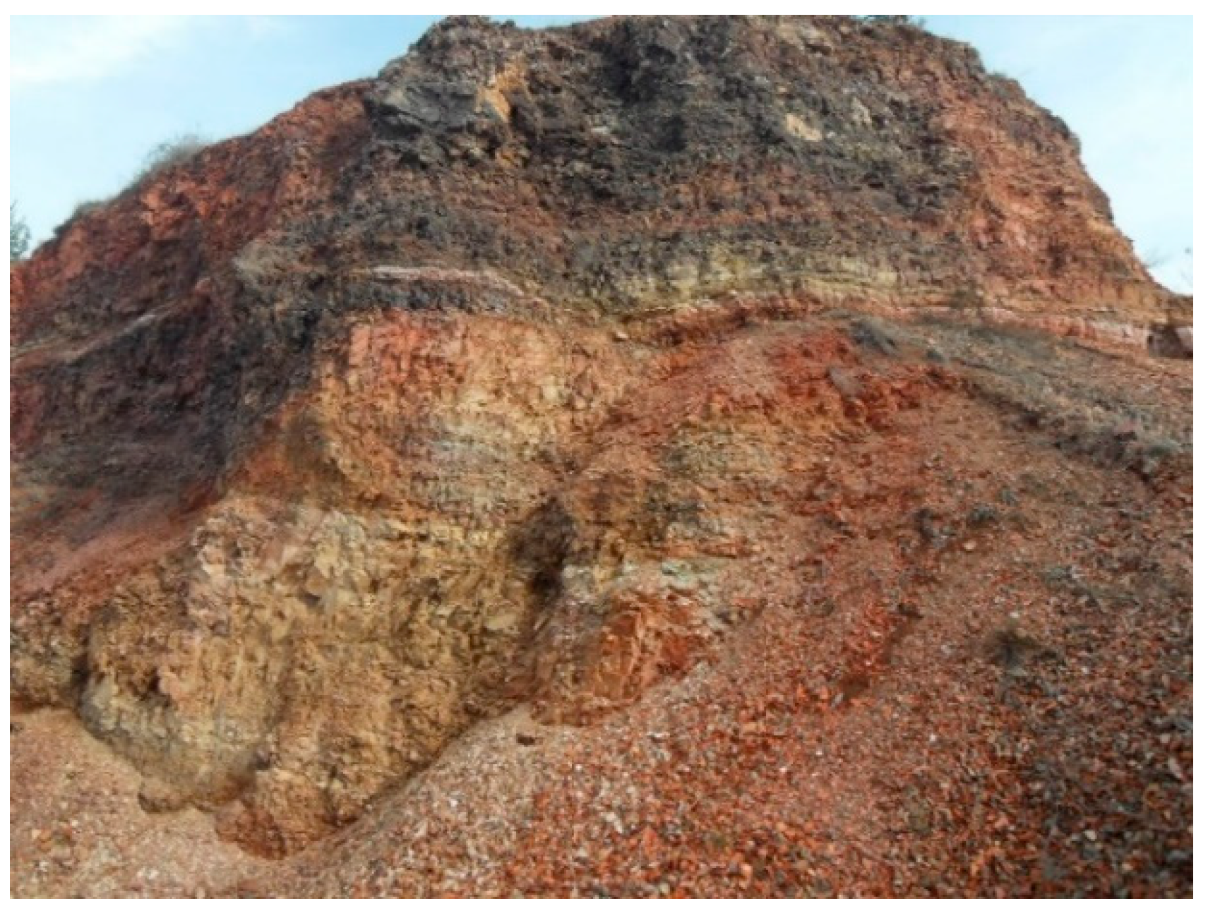
Figure 2.
Chemical composition of red solid clays from Crvena Mogila locality.
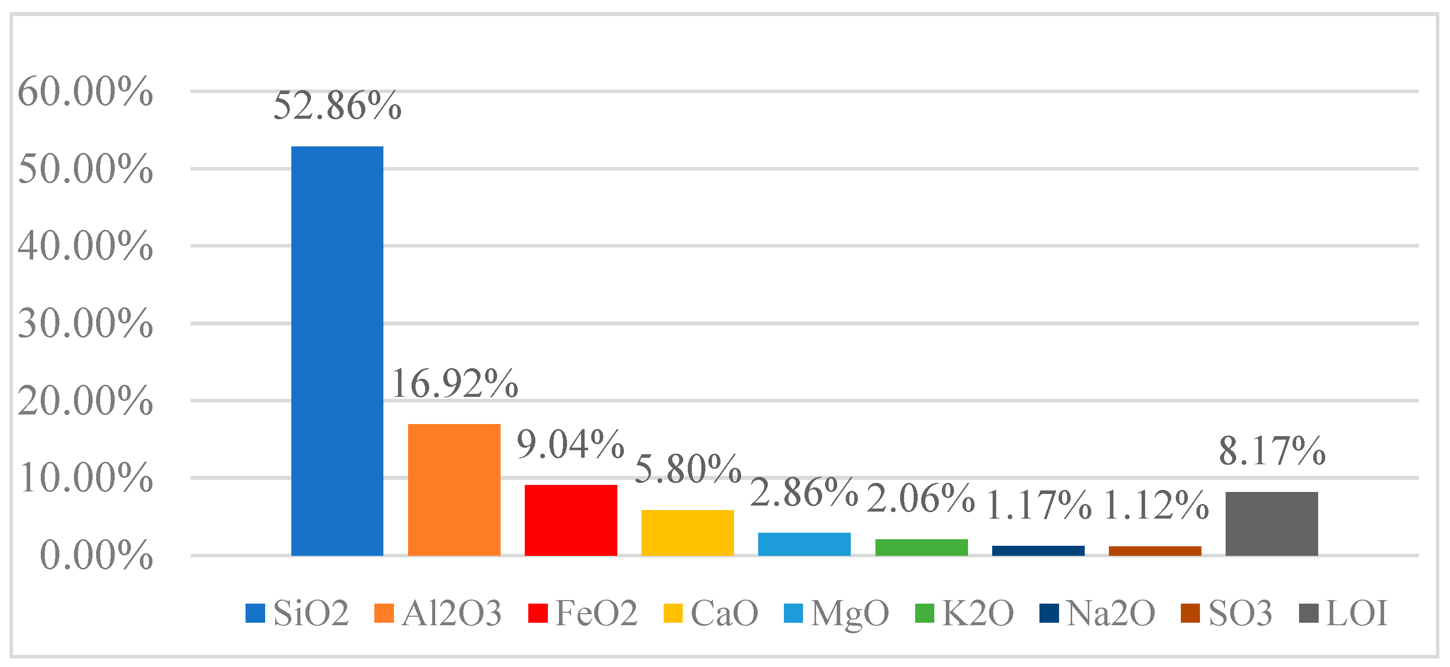
Figure 3.
Irregularly shaped monolithic rock and cubic test samples 5x5x5 cm.
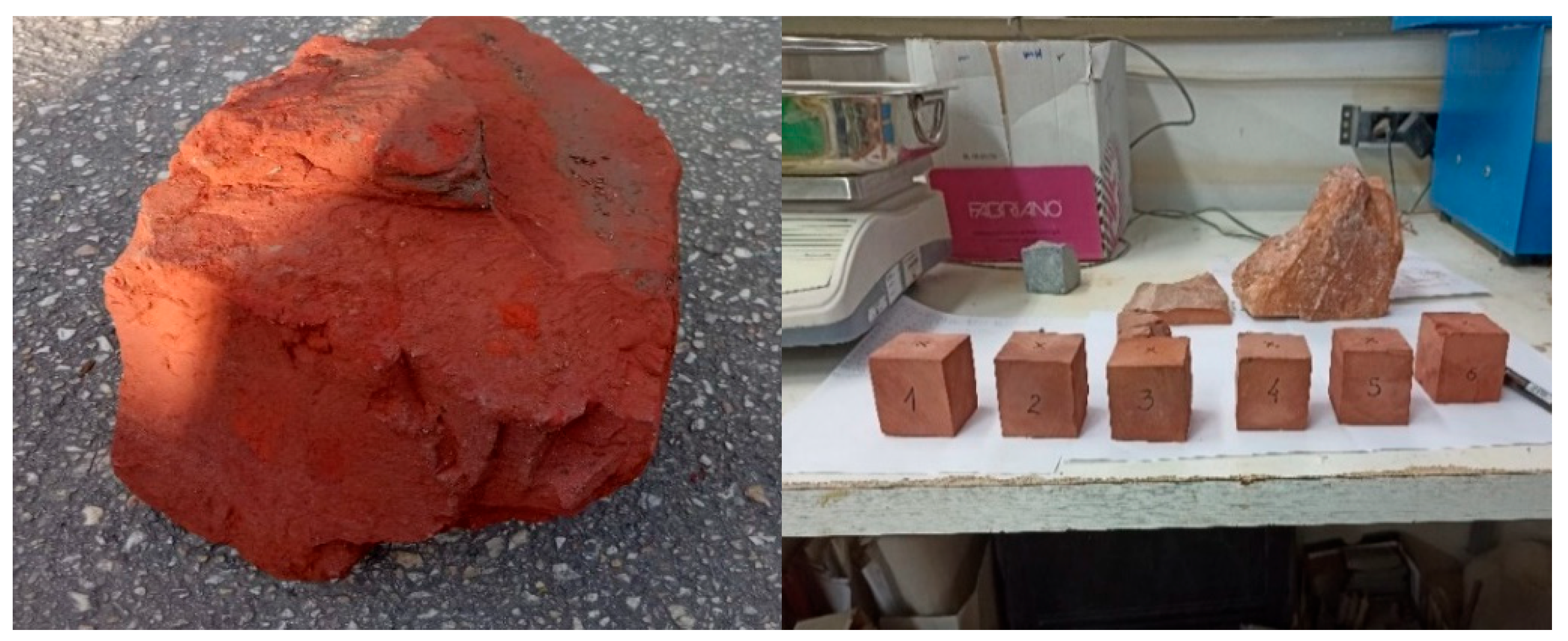
Figure 4.
a) Compressive strength test, b) Cracked sample, c) Samples immersed in water.
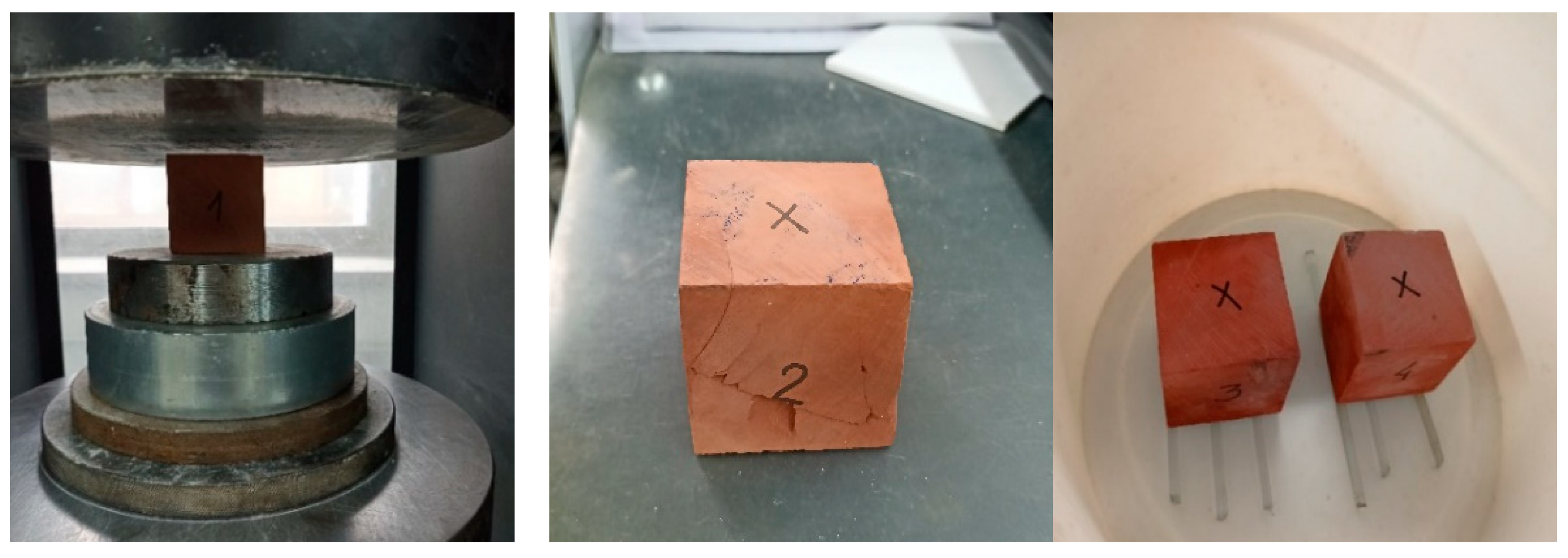
Figure 5.
a) Saturated sample; b) Failure of saturated sample.
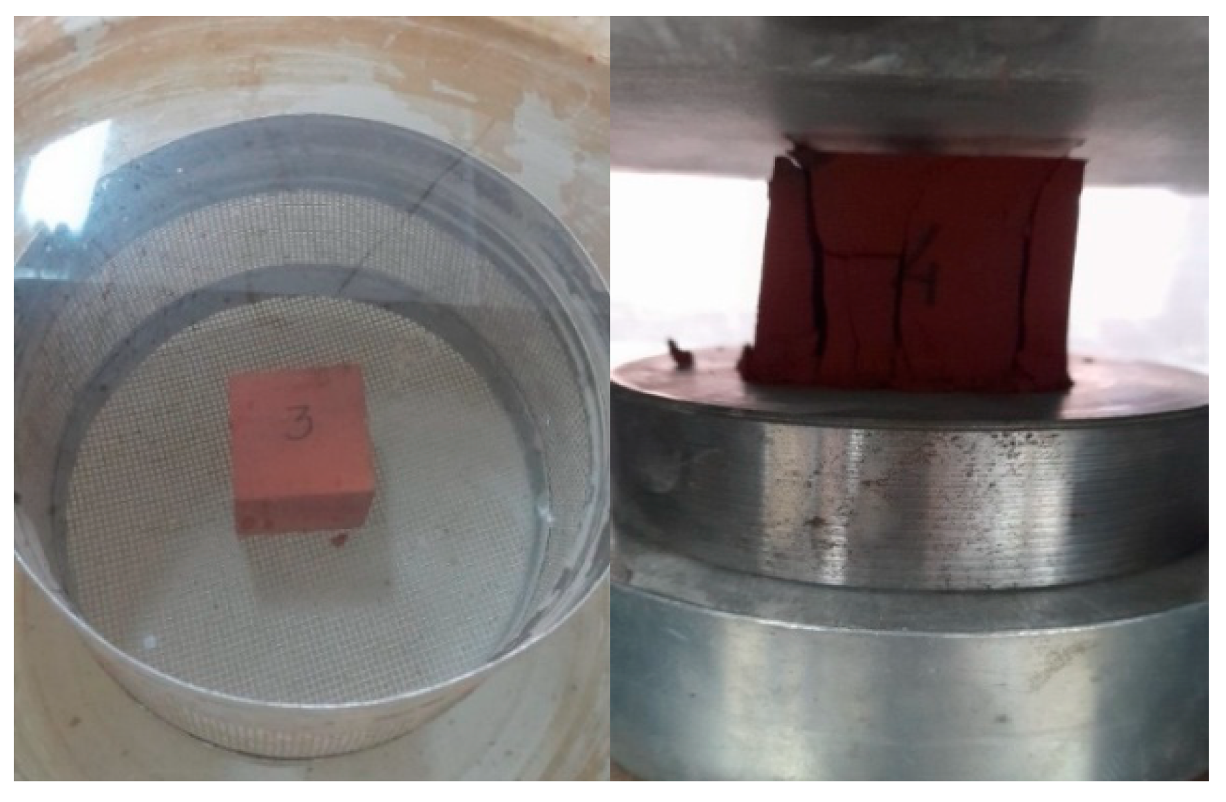
Figure 6.
Capillary absorption of water of the natural stone.
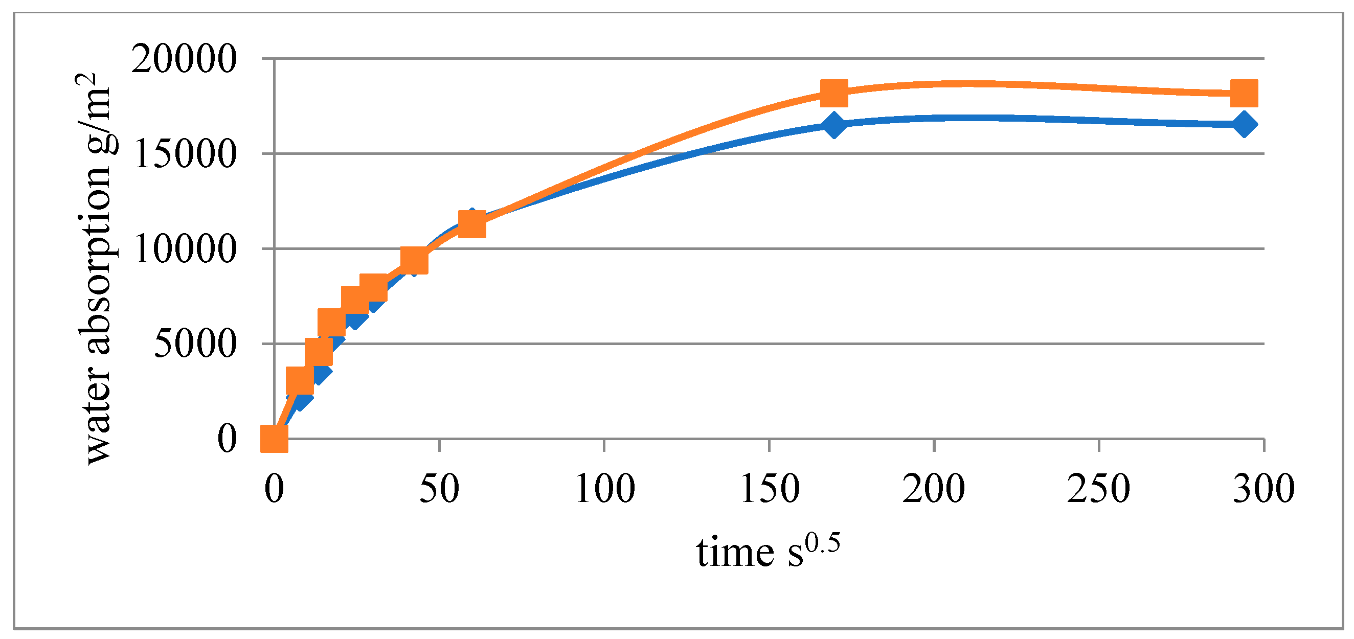
Figure 7.
a) Fine red solid clay aggregate; b) Composite blocks type I with 5 hollows and type II with 6 hollows.
Figure 7.
a) Fine red solid clay aggregate; b) Composite blocks type I with 5 hollows and type II with 6 hollows.
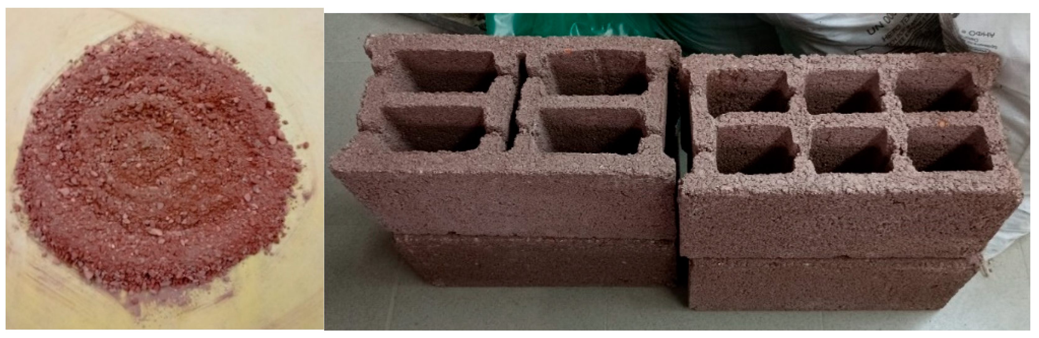
Figure 8.
Determination of compressive strength of composite blocks according [22].
Figure 8.
Determination of compressive strength of composite blocks according [22].
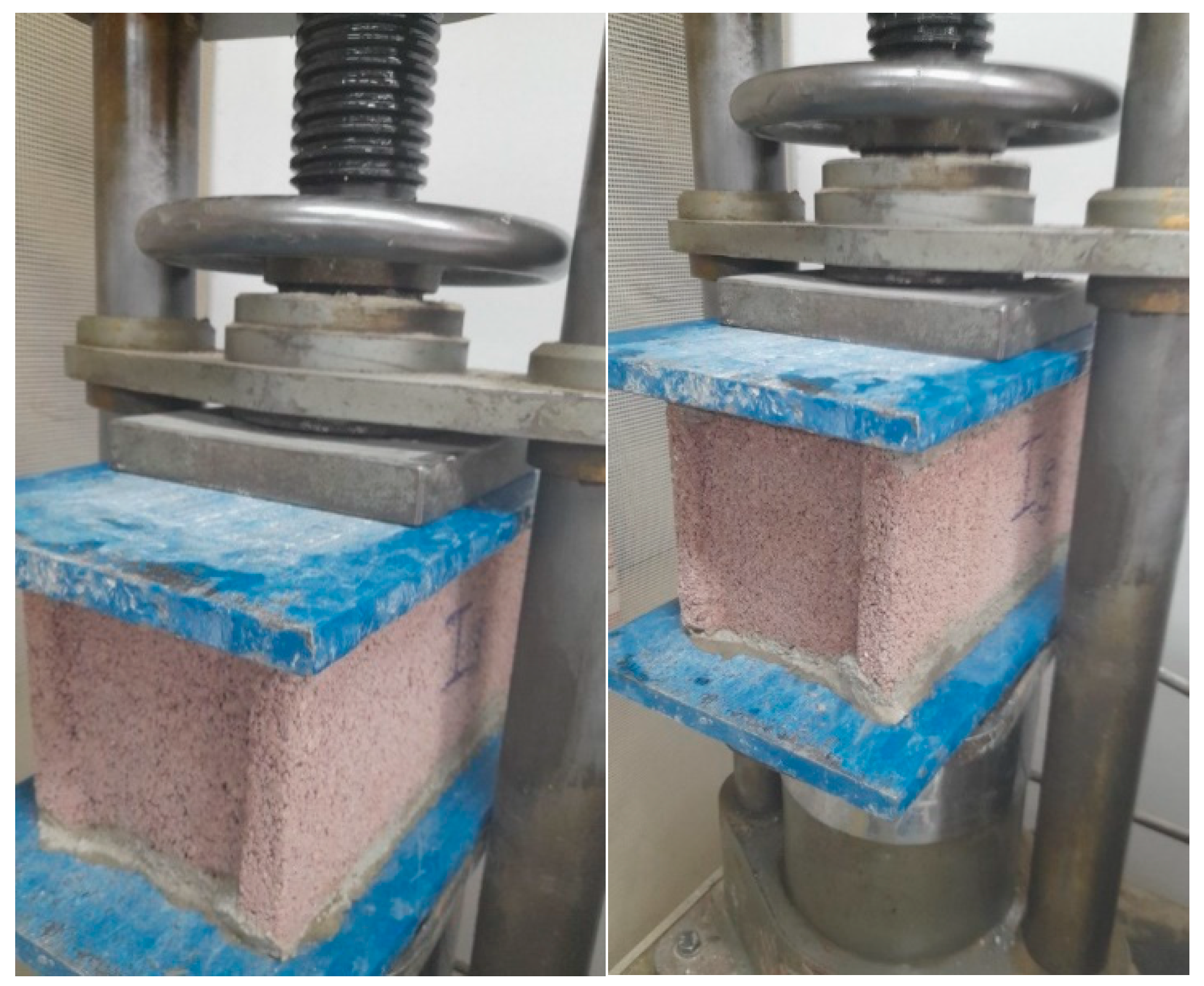
Figure 9.
Instrument Heat Flow Meter and three testing samples.
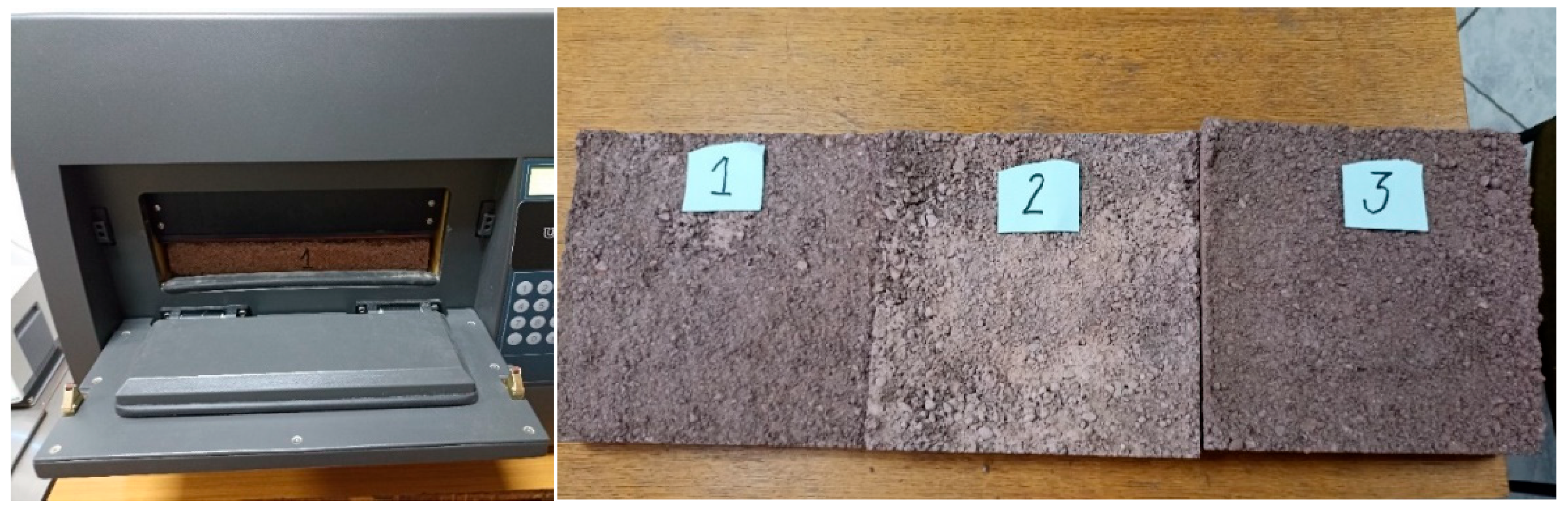
Figure 10.
Thermal conductivity λ of three samples with red clay.
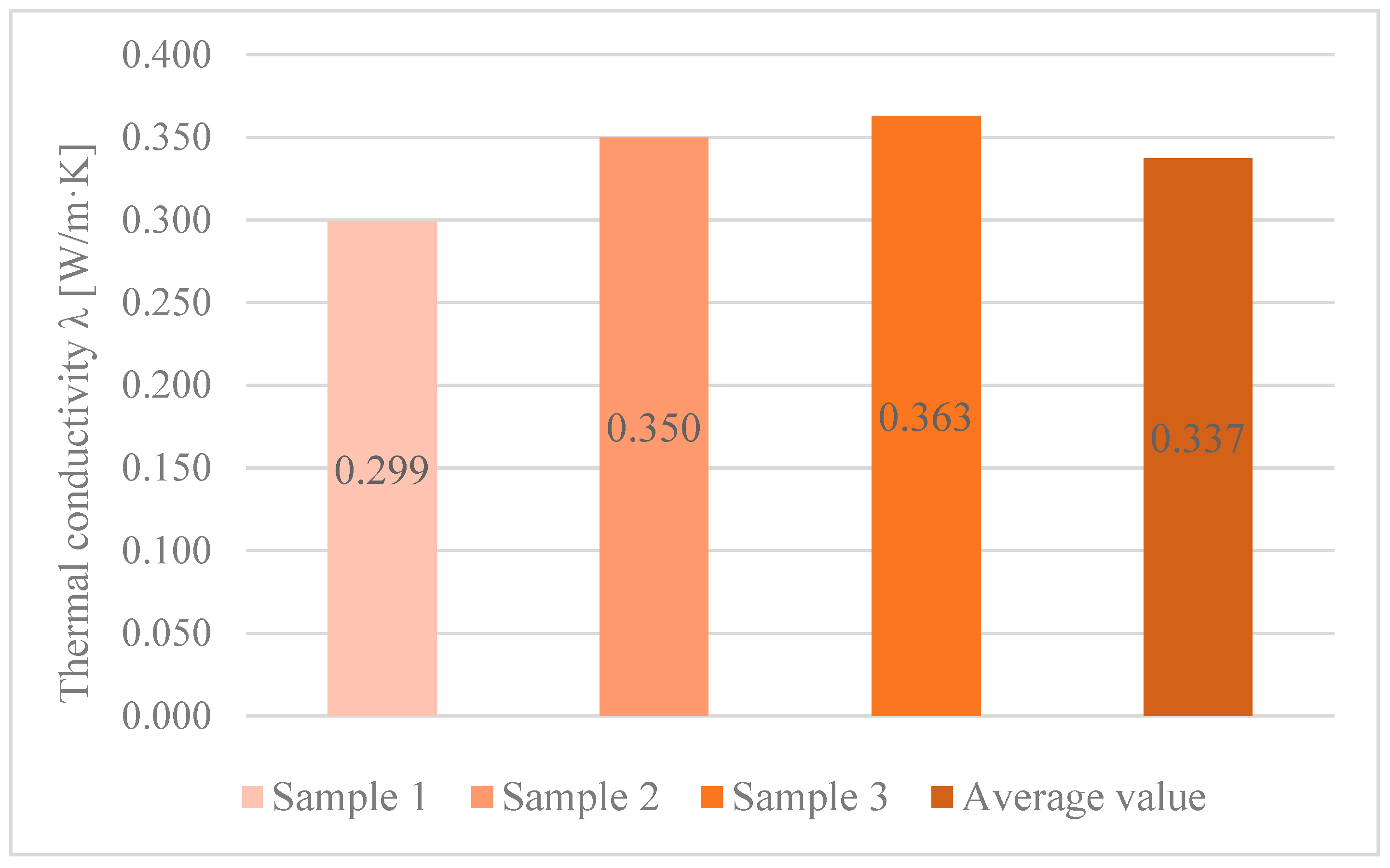
Figure 11.
Compressive strengths of the red solid clay samples in different conditions.
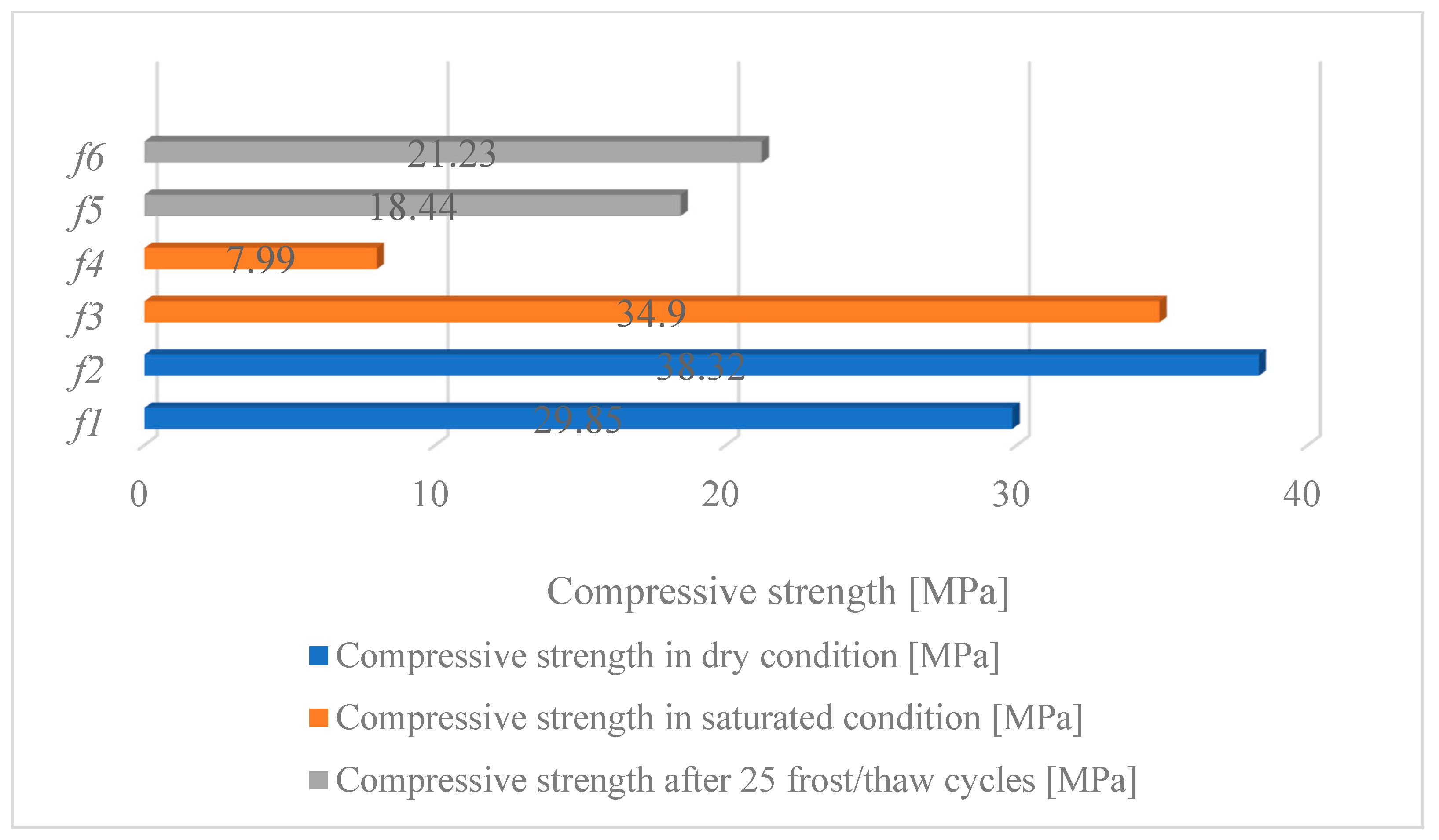
Figure 12.
Density and water absorption of red solid clay and natural aggregate.
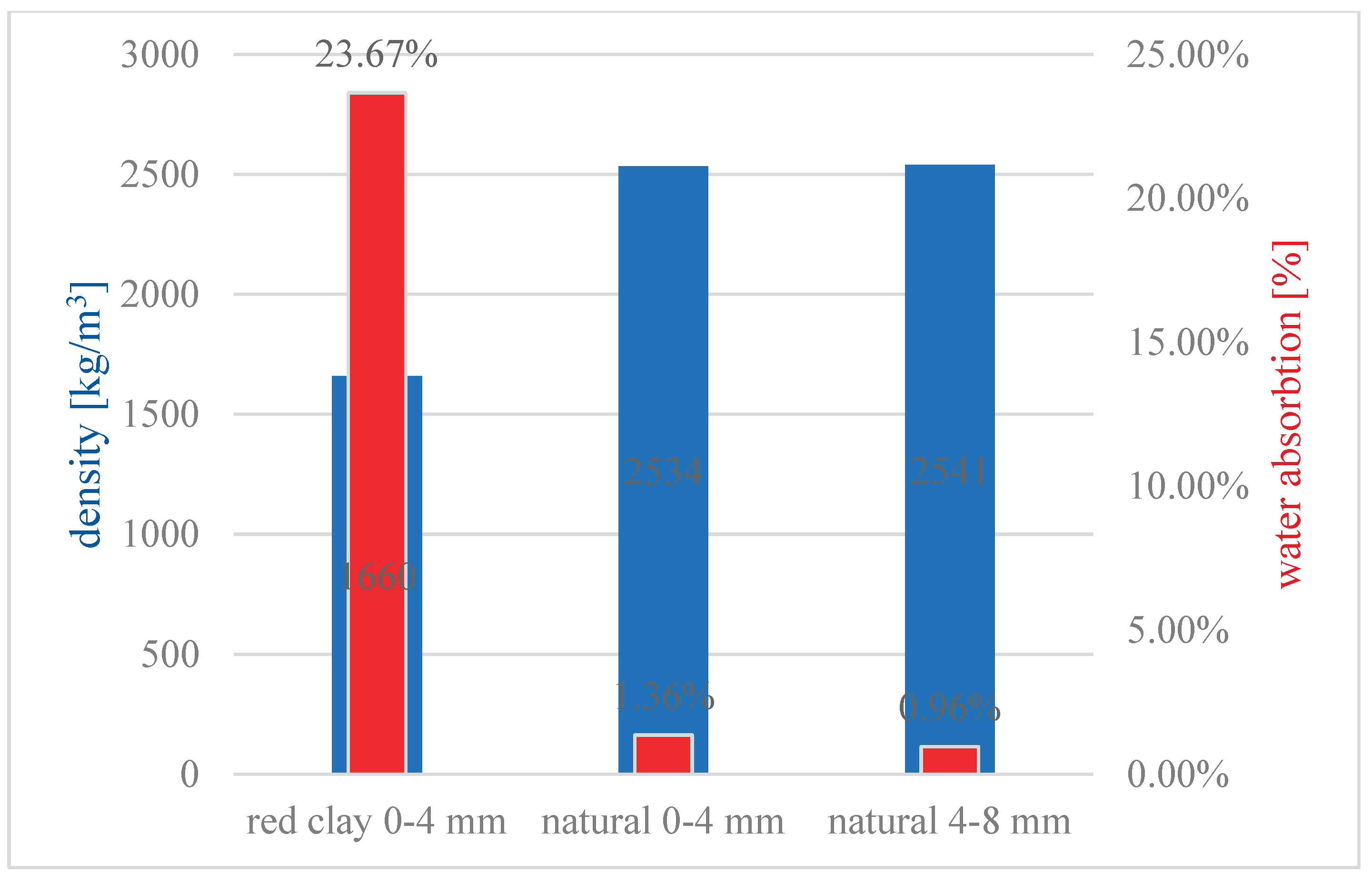
Table 1.
Chemical analysis of red solid clay aggregate from "Crvena Mogila" locality.
| Parameters | Results |
|---|---|
| Chloride content () | 0,17 % |
| Contents of sulfates () soluble in acid | 0,74 % |
| Organic substances | none |
Table 2.
Compressive strength of red solid clay samples.
| Sample | Dimensions [cm] |
mass [g] |
Volume [cm3] |
Density [kg/m3] |
Force [kN] |
Compressive strength [MPa] | Condition | ||
|---|---|---|---|---|---|---|---|---|---|
| d | b | h | m | V | γ | F | |||
| 1 | 5,19 | 5,10 | 5,18 | 188,10 | 137,11 | 1371,90 | 79,00 | 29,85 | Dry |
| 2 | 5,10 | 5,25 | 5,21 | 197,80 | 139,50 | 1417,94 | 102,60 | 38,32 | |
| Average value | 5,15 | 5,18 | 5,20 | 192,95 | 138,30 | 1394,92 | 90,80 | 34,08 | |
| 3 | 5,11 | 5,26 | 5,23 | 209,60 | 140,58 | 1491,02 | 93,80 | 34,90 | Saturated |
| 4 | 4,98 | 5,05 | 5,05 | 146,60 | 127,00 | 1154,31 | 20,10 | 7,99 | |
| Average value | 5,05 | 5,16 | 5,14 | 178,10 | 133,79 | 1322,66 | 56,95 | 21,45 | |
| 5 | 5,05 | 4,96 | 5,02 | 149,90 | 125,74 | 1192,13 | 46,20 | 18,44 | Frost |
| 6 | 5,19 | 5,21 | 5,11 | 202,90 | 138,17 | 1468,44 | 57,40 | 21,23 | |
| Average value | 5,12 | 5,09 | 5,07 | 176,40 | 131,96 | 1330,29 | 51,80 | 19,84 | |
Table 4.
Real and apparent density, total and open porosity of the samples.
| 1. | Real density | MKS EN 1936 | 1390 | ||
| 2. | Apparent density | 2630 | |||
| 3. | Total porosity | % | 52,85 | ||
| 4. | Open porosity | % | 47,15 |
Table 5.
Recipe for composite masonry blocks (1.0 m3).
| Ingredient | Cement | Water | w/c | additive | Aggregate dmax = 8 mm | ||
|---|---|---|---|---|---|---|---|
|
Fine red solid clay aggregate (fraction 0-4 mm) |
Fine aggregate (fraction 0-4 mm) |
Fine aggregate (fraction 4-8 mm) |
|||||
| Quantity | 300 kg | 100 kg | 0,33 | / | 900 kg (50%) | 400 kg (22%) | 500 kg (28%) |
Table 6.
Compressive strength, net and gross density, water absorption and percentage of pores and voids of the blocks.
Table 6.
Compressive strength, net and gross density, water absorption and percentage of pores and voids of the blocks.
| Specimen | Compressive strength | Dry mass mdry,u | Mass after soaking | Gross volume Vg,u | Net volume Vn,u | Gross dry density | Net dry density | Water absorption | Percentage of pores and voids |
|---|---|---|---|---|---|---|---|---|---|
| [MPa] | [g] | [g] | [104mm3] | [104mm3] | [kg/m3] | [kg/m3] | [%] | [%] | |
| I – 1 | 3,00 | 13178 | 15114 | 1397 | 812 | 943 | 1622 | 14,69 | 44,48 |
| I – 2 | 3,26 | 13389 | 15322 | 1381 | 808 | 970 | 1658 | 14,44 | 43,12 |
| Average block I | 3,1 | - | - | - | - | 956 | 1640 | 14,56 | 44 |
| II – 1 | 3,93 | 12466 | 15114 | 1390 | 603 | 897 | 1601 | 21,24 | 45,70 |
| II – 2 | 4,32 | 12796 | 15322 | 1393 | 623 | 919 | 1600 | 19,74 | 44,86 |
| Average block II | 4,1 | - | - | - | - | 908 | 1601 | 20,49 | 45,28 |
Table 8.
Comparison of the percentage of pores, degree of water absorption and thermal conductivity.
Table 8.
Comparison of the percentage of pores, degree of water absorption and thermal conductivity.
| Properties | Material | ||
|---|---|---|---|
| Composite block with red solid clay (tested results) | Ordinary concrete block | Autoclaved lightweight concrete block | |
| Percentage of pores and voids [%] | 44,00% - 45,28% | 18,50% - 26,40% | 60,00% – 80,00% |
| Degree of water absorption [%] | 14,56% - 20,49% | 4,40% - 7,55% | 40,00% - 80,00% |
| Thermal conductivity λ [W/m∙K] | 0,337 | 2,3 | 0,14 |
Disclaimer/Publisher’s Note: The statements, opinions and data contained in all publications are solely those of the individual author(s) and contributor(s) and not of MDPI and/or the editor(s). MDPI and/or the editor(s) disclaim responsibility for any injury to people or property resulting from any ideas, methods, instructions or products referred to in the content. |
© 2025 by the authors. Licensee MDPI, Basel, Switzerland. This article is an open access article distributed under the terms and conditions of the Creative Commons Attribution (CC BY) license (http://creativecommons.org/licenses/by/4.0/).
Copyright: This open access article is published under a Creative Commons CC BY 4.0 license, which permit the free download, distribution, and reuse, provided that the author and preprint are cited in any reuse.


