Submitted:
12 June 2025
Posted:
13 June 2025
You are already at the latest version
Abstract
Fused Filament Fabrication enables the manufacturing of complex polymer components. However, surface finish and dimensional accuracy remain key limitations for their integration into functional assemblies. This study explores the potential of conventional turning as a post-processing strategy to improve the geometric and surface quality of PLA reinforced with carbon fiber parts produced by FFF. Machinability was evaluated through the analysis of cutting forces, thermal behaviour, energy consumption, and surface integrity under varying cutting speeds, feed rates, and specimen slenderness. The results indicate that feed is the most influential parameter across all performance metrics, with lower values leading to improved dimensional accuracy and surface finish. Nevertheless, the surface roughness is higher than that of metals, and deviations in geometry along the length of the specimen have been observed. A critical shear stress of 0.237 MPa has been identified as the limit for interlayer failure, defining the boundary conditions for viable cutting operation. Compared to long printing times in high-resolution FFF, the addition of machining step significantly reduced fabrication time while enhancing part quality. These findings support the use of machining operations as a viable and efficient post-processing method for improving the functionality of polymer-based components produced by additive manufacturing.
Keywords:
Additive manufacturing
; Fused Filament Fabrication
; PLA carbon fiber
; machinability
; dimensional accuracy
; surface roughness
; post-processing
; interlayer failure
1. Introduction
Additive manufacturing (AM) has emerged as a manufacturing process that offers greater design freedom, material efficiency and the ability to produce complex geometries in advance of traditional manufacturing processes [1]. Although the initial application of AM was focused on its use for rapid prototyping, with continued advances in materials, hardware and process control, AM has evolved into a robust manufacturing method capable of producing functional end-use components with mechanical properties and precision suitable for industrial applications [2,3].
Among the various additive manufacturing technologies, Fused Filament Fabrication (FFF) is widely used due to its accessibility, versatility and cost effectiveness. FFF allows using a wide range of materials, which makes it possible to adapt to varying functional and structural requirements [4]. This flexibility makes it suitable for applications ranging from model making to high performance parts used in demanding environments.
With the capabilities of FFF manufacturing technology continuously advancing, there has been a growing focus on developing and utilising reinforced materials to overcome some of the inherent limitations of standard filaments [5]. The incorporation of reinforcing, such as fibres, particles, or blends, has been shown to be an effective strategy for enhancing the mechanical, thermal, and dimensional stability of printed components [6,7], thereby expanding the range of functional applications for FFF-manufactured parts.
Among the different reinforced materials, polylactic acid (PLA) reinforced with short carbon fibres has emerged as a material of choice [8]. This material combines the ease of processing and printability of PLA with the enhanced mechanical properties provided by carbon fibre reinforcement [9,10]. Furthermore, PLA is a biodegradable material under controlled conditions, making it one of the most environmentally sustainable materials used in additive manufacturing. Incorporating carbon fibres into the PLA matrix can be achieved without significantly compromising this sustainability profile, providing a balanced solution that supports both technical performance and environmental responsibility [11,12].
Surface finish is a critical aspect of any manufactured part as it directly influences its aesthetic appearance, functional performance, and dimensional accuracy. In addition, the surface topography can affect properties such as friction, wear resistance, sealing ability, and even mechanical strength [13,14,15].
Achieving an appropriate surface finish is often essential for the part to meet industrial requirements or to be integrated into larger assemblies without further modification. Consequently, improving the surface finish is often necessary to ensure functionality, reliability and performance. This has led to increased interest in post-processing techniques such as mechanical finishing, chemical smoothing or hybrid manufacturing strategies [16,17].
Despite the numerous advantages offered by FFF, one of its most notable limitations is the poor surface finish of the printed parts. Due to the layer-by-layer deposition process, surfaces often exhibit visible layer lines, step effects, and texture variations, especially on sloped or curved geometries [18]. These surface irregularities can compromise the functionality of the part in precision assemblies or in applications where smooth surfaces are critical [19].
A common strategy for improving surface quality in FFF is to reduce the layer height. However, the total printing time increases significantly as more layers are required to build the same geometry [20]. This trade-off between surface quality and production efficiency limits the scalability of the process, particularly in industrial contexts where time and cost are critical factors. Therefore, the application of complementary post-processing solutions can improve surface quality without negatively impacting the manufacturing process.
In this sense, machining can be considered as a viable post-processing strategy to improve the surface finish and dimensional accuracy of FFF manufactured parts, producing smooth surfaces and fine tolerances in a reduced manufacturing time. This makes machining an effective and flexible post-processing solution, particularly when it is essential to maintain both mechanical integrity and surface finish.
Machining processes have been extensively studied in the context of metals [21,22,23]. Nevertheless, there is significantly less research focused on the machining of polymers, especially those produced by additive manufacturing. Polymers exhibit different behaviour under cutting conditions due to their lower thermal conductivity, viscoelastic properties and heterogeneous microstructures [24]. In this context, the concept of machinability provides a comprehensive framework for evaluating how a material responds to machining. The assessment of machinability includes not only the resulting surface quality, but also the thermal and mechanical loads generated during the process, as well as its energy efficiency [25,26]. These parameters provide valuable insight into both the performance of the machining process and the response of the material and can be used to optimise cutting conditions for improved results.
The literature shows a set of research that evaluates the machining of PLA samples obtained by different manufacturing processes. Cloëz et al. [27] investigated the machinability of injection-molded PLA under dry milling conditions. The study evaluated the influence of cutting speed and feed per tooth on cutting forces and surface roughness. Discontinuous chips were consistently observed, characteristic of the brittle behaviour of PLA. Cutting forces decreased with increasing cutting speed. Nevertheless, surface roughness increased under the same conditions due to thermal softening and localized surface deformation. Regarding the feed rate, this variable increase led to significantly higher roughness.
Lazăr et al. [28] studied the surface roughness behaviour of 3D-printed PLA components subjected to CNC end milling, aiming to develop regression models for predicting roughness based on cutting parameters. The specimens were printed using FFF and then machined under varying cutting speeds (2250–4000 rev/min) and feed rates (100–1024 mm/min). Results showed that average surface roughness (Ra) increased with feed rate and decreased slightly with cutting speed. The study concluded that fine milling significantly improves surface finish on FFF-printed PLA parts, and that predictive functions can assist in process planning for functional or aesthetic surface requirements.
Kowalska et al. [29] studied the influence of CNC peripheral milling on the surface roughness and tensile strength of parts made from polylactic acid (PLA) fabricated by FFF. The investigation aimed to evaluate how structural thickness affects post-processing results. The results showed that surface roughness (Ra) was significantly reduced after machining. However, tensile strength decreased in all machined specimens. This was attributed to the material removal occurring close to the load-bearing outer perimeter, compromising structural continuity.
Drilling has also been an operation that has been considered in the machining of PLA. This is the case of Anbuchezhiyan and Vignesh [30], that investigated the micro-drilling performance of a PLA composite reinforced with 12% bronze nanoparticles, manufactured using FFF. The study aimed to assess the influence of cutting parameters on material removal rate, delamination, hole quality, and tool wear under dry machining conditions. The results showed that material removal rate increased with tool diameter, spindle speed, and feed rate. However, these same conditions led to the highest delamination, up to 33%. Lower feed rates and smaller tool diameters resulted in minimal delamination. Hole circularity remained stable at higher spindle speeds due to thermal softening of the material, which facilitated chip evacuation. The study concluded that feed rate was the most influential parameter on delamination and overall drilling performance, highlighting the need to balance productivity and part quality during micro-machining.
A micro-drilling optimization study on a PLA composite reinforced with 14 wt.% bronze, fabricated by FFF, were carried out in [31]. The aim was to evaluate the influence of drilling parameters on material removal rate (MRR) and delamination using Response Surface Methodology (RSM). The operation was conducted under dry conditions, varying the cutting speed (2000–3000 rev/min), feed rate (0.1–0.3 mm/min), and width of cut (0.5–0.9 mm). Results showed that MRR increased with all three parameters. In addition, the maximum MMR value obtained showed the highest delamination percentage. Lower feed rates and smaller tool diameters led to reduced delamination. The RSM model confirmed that feed rate and width of cut were the most significant variables influencing delamination, while spindle speed had a more moderate effect.
The tool geometry influence on MMR was analysed in [32]. The machinability of a novel PLA matrix reinforced with 15% short carbon fiber (CF), under dry drilling conditions, using two different tool geometries: a step drill bit (experimental group) and a twist drill bit (control group) was studied. The specimens were fabricated by injection moulding. Results showed that tool geometry has a critical influence on drilling efficiency of CF-reinforced PLA composites. While CF addition generally reduces MRR due to higher material strength, the step drill compensated this limitation, offering improved machining productivity.
Madhan Kumar and Jayakumar [33] investigated the drilling performance of biodegradable PLA composites reinforced with 5 vol.% of sawdust, rice husk, and bagasse, processed by hot compression moulding. The aim was to evaluate the influence of cutting parameters on delamination and surface roughness. The composites were machined under dry conditions. Drilling parameters were varied across four levels using a Taguchi L16 design: spindle speed (500–2000 rev/min), feed rate (50–125 mm/min), and drill diameter (8–14 mm). The results showed that feed rate had the greatest influence on both delamination and surface roughness, followed by spindle speed and composite type. Higher feed rates and larger drill diameters increased delamination due to greater thrust forces, while increased spindle speed reduced delamination by thermally softening the matrix. In addition, Ra value was lowest for PLA with bagasse, which also exhibited better hardness and impact resistance.
Regarding turning operations of polymers, Bertolini et al. [34] investigated the machinability of polyamide 6 (PA6) during CNC turning under different cooling strategies, focusing on how cutting conditions and temperature influence key material and surface responses. The study compared conventional flood cooling with two cryogenic setups using liquid nitrogen. Machining was conducted with cutting speeds between 50 and 200 m/min, and depths of cut from 0.25 to 1 mm, remaining constant the feed rate (0.1 mm/rev)
The study measured several indicators of machinability, such us cutting temperature, surface roughness parameters, surface hardness and chip morphology. Results showed that higher cutting speeds and depths of cuts increased surface temperature and promoted thermal softening under flood conditions, leading to continuous chip formation and lower hardness. Cryogenic machining also increased surface hardness compared to flood cooling.
Jabłońska and Łastowska [35] evaluated the effect of turning on the surface quality and geometrical precision of PETG parts fabricated by FFF. The study aimed to assess how the combination of additive manufacturing and subtractive post-processing could enhance the surface finish and dimensional characteristics of polymer components. Cylindrical samples (Ø30 × 5–60 mm) were printed with two different layer heights (0.1 mm and 0.2 mm) and subsequently subjected to dry longitudinal turning on a conventional lathe. The turning process was conducted varying feed rates, remaining constant the cutting speed and the depth of cut, and all cutting operations were performed without cutting fluid.
The results demonstrated a significant reduction in surface roughness after machining, particularly for specimens printed with smaller layer heights and machined at lower feed rates. Additionally, roundness errors decreased notably after machining, indicating an improvement in dimensional accuracy. Therefore, authors considered that dry turning is an effective method to improve the surface quality and roundness of FFF-printed PETG parts, and that layer height and feed rate are critical parameters influencing the final quality of the machined surface.
Although numerous studies have addressed the machining of PLA, most of the existing research has focused on milling and drilling operations, while turning remains largely unexplored, despite being particularly suitable for parts with rotational symmetry. Furthermore, while some works have begun to assess the machinability of PLA and its composites, there is still a lack of in-depth investigation into the influence of cutting parameters on key indicators such as cutting forces and temperature. In addition, energy consumption during polymer machining has not been systematically evaluated, even though it is a critical factor in process efficiency and sustainability.
Surface roughness has received attention in the literature; however, studies rarely explore its correlation with a wide range of cutting parameter combinations, limiting the understanding of how process settings affect surface quality. Similarly, form errors and dimensional deviations in machined PLA parts have not been extensively addressed, even though the low stiffness of PLA composites may make them more susceptible to deformation during cutting, ultimately affecting the dimensional accuracy and functional integrity of the final part.
Considering these gaps, the present study aims to analyse the machinability and geometric characteristics of PLA reinforced with short carbon fibre, fabricated by Fused Filament Fabrication (FFF) and subsequently machined through turning, with a comprehensive evaluation of cutting forces, cutting temperature, energy consumption, dimensional accuracy, surface quality and form deviation across a broad set of cutting conditions.
2. Materials and Methods
The material used in this study was a polylactic acid (PLA) matrix composite that had been reinforced with short carbon fibres (CF). The selection of carbon fibre provides better mechanical properties in comparison to unmodified PLA, including increased stiffness, strength, and dimensional stability. Additionally, PLA matrix possesses the advantage of a biodegradable material.
The initial sample geometry for this study was a solid cylindrical specimen designed for further processing by turning operations, the geometry of which can be related to rotational components of mechanisms such as a drive shaft. The dimensions corresponded to a 20 mm outer diameter and a total length of 200 mm. The sample was manufactured by additive manufacturing using Fused Filament Fabrication (FFF) technology. A specific printing strategy was adopted in which the part was built in a vertical orientation, so that the material was deposited layer by layer in a direction perpendicular to the axis of revolution.
This configuration has been chosen for two main reasons. Firstly, it eliminates the need for support structures, simplifying the manufacturing process and minimising the risk of surface defects caused by contact with the support material. Secondly, this orientation allows the subsequent turning operation to interact directly with the interlayer planes, which are often the weakest regions of FFF-printed components, allowing for an assessment of any post-processing limitations. In addition, the chosen geometry results in a length to diameter (L/D) ratio, which can be a limiting factor due to bending deformation that can occur during machining, especially at higher cutting loads. This feature is expected to influence the machinability and surface quality of the final part, so it was also taken into account for the evaluation of the feasibility of turning as a post-processing operation for PLA-CF parts manufactured with FFF.
The specimens have been manufactured using a Raise3D Pro2 FFF printer. The slicing and process control were performed using the ideaMaker software. The manufacturing conditions applied in the printing process can be observed in Table 1.
The samples have been manufactured using two different layer heights. One sample has been printed with a layer height of 0.05 mm, considering a finer layer resolution because it contributes to improve dimensional accuracy and surface quality in FFF printed components [36]. However, this high resolution of the specimen means an increase in the manufacturing time, being in this case necessary a time of 24 hours and 35 minutes, reducing the manufacturing efficiency in a high number of parts. Therefore, to explore the use of machining as a post-processing strategy to improve surface characteristics and reduce printing time, a set of samples was fabricated using a thicker layer height of 0.30 mm. This adjustment resulted in a substantial reduction in fabrication time, reducing it to 4 hours and 9 minutes.
Once the specimens have been manufactured by FFF, they have been subjected to a longitudinal turning operation in order to evaluate the feasibility of machining as a post-processing strategy. The turning operation has been carried out on an EMCO EMCOTURN E45 CNC lathe. The machining has been performed in dry conditions by environmental reasons, but with the application of compressed air directed at the cutting zone.
The use of compressed air served to facilitate chip evacuation and to prevent chip adhesion to the turned surface. Preliminary tests revealed that the elevated temperatures generated during the cutting process could cause softened PLA chips to stick to the turned machined surface, affecting the surface finish. The airflow prevented this by removing the chips from the cutting area as they formed.
The cutting tool used in the turning operation was a DCMT 11T308-14 IC20 insert, manufactured by Iscar, and mounted on an SDJCR 2020K11 tool holder. The insert geometry corresponds to a 66° principal cutting edge angle, which was specifically selected to prevent tool interferences that can occur when reducing the diameter of the workpiece, thereby minimizing the risk of local deformation or dimensional inaccuracies during the turning process. In addition, this tool orientation causes the resulting forces to have a significant component between layers of the FFF-printed material, generating stresses between adjacent layers, which increases the risk of delamination or fracture. This condition is intentionally introduced to evaluate the structural integrity of the material undergoing machining and to assess the feasibility of turning as a post-processing operation for fabricated PLA-CF parts. Other cutting geometry characteristics are shown in Table 2.
A set of cylindrical turning operations has been performed by combining two cutting speeds (vc) and two feed rates (f), remaining constant the depth of cut (ap), which values can be observed in Table 3. The selected values for both cutting speed and feed rate represented extreme conditions to evaluate the influence of these boundaries on the machining capacity of the printed material.
Each turning operation has been carried out along a machined length of 150 mm on the cylindrical surface of the specimen. The machining operation conditions have been repeated for each of the combinations of cutting parameters, reducing in each case the final specimen diameter until part failure occurred. This approach has provided a better understanding of the mechanical limitations of machining PLA-CF fabricated by FFF as a post-processing method. It is important to notice that all machining tests have been performed using the same cutting edge, as no visible tool wear or degradation has been observed. This ensured that the results have not been influenced by changes in tool condition, allowing for a consistent evaluation of machining performance under varying process parameters.
To evaluate the machinability of PLA-CF components manufactured by FFF, real-time measurements (on-line monitoring) have been taken of three key process values: temperature in the cutting zone, cutting forces and electrical energy consumption (Figure 1), to characterize the thermal, mechanical and energetic responses of the material throughout the machining process.
The measurement of cutting temperature was carried out using a FLIR A305sc infrared thermal imaging camera, positioned to ensure a clear view of the tool–workpiece interface. The emissivity of the carbon fibre-reinforced PLA material was determined in accordance with the UNE-EN ISO 4288:1998 standard [37], which provides guidelines for assessing surface characteristics relevant to infrared thermography. This calibration step provided a value of 0.95 for the PLA-CF emissivity. The thermographic data have been processed using FLIR ResearchIR software, which enabled frame-by-frame analysis and extract the cutting zone temperature.
The cutting forces have been measured with a Kistler 9257B piezoelectric dynamometer obtaining the value of three orthogonal force components: Fx (passive forces), Fy (cutting forces) and Fz (feed forces). These forces have been recorded continuously throughout the machining cycle to evaluate the mechanical load on both the tool and the workpiece. The DynoWare software was used to record and visualise the force data. From the collected data, average force values have been considered for each cutting parameters combination for the cutting length of 150 mm.
The electrical energy consumption during the turning process has been evaluated to determine the influence of the cutting parameters on the machining. This parameter complements the machinability assessment by providing information on the energy efficiency and sustainability of the process. The measurement process was performed with a Fluke 1732 network analyser, which was connected to the power supply of the machining system, obtaining the electrical power (P) and the energy consumption per second (E). Data acquisition was analysed using the Fluke Energy Analyze Plus software.
Once the machining process has been carried out, an off-line evaluation was conducted to assess the geometrical quality of the machined parts and a chip morphology analysis (Figure 2).
A representative sample of the chip has been collected to carry out the morphological analysis. Care has been taken during collection to avoid altering the shape or surface characteristics of the chip, ensuring that the sample reflected the cutting process conditions. The morphological analysis has been performed using a Stereo Optical Microscope (SOM) with a ZEISS stereo optical microscope equipped with an AxioCam digital camera. This image process enabled a qualitative assessment of chip formation and helped identify the effects of different cutting parameters on chip morphology. The visual information obtained supported the interpretation of the machinability of PLA-CF and complemented the analysis of cutting forces and surface finish.
The geometry analysis has been structured into three levels: Dimensional Accuracy Assessment, Macrogeometric Deviation Evaluation, and Microgeometric Deviation Characterization. These levels are used to evaluate the impact of the turning operation on the final geometry of FFF manufactured parts. In addition, the chip observation allows to complete the machinability analysis carried out in the on-line monitoring results.
To evaluate the dimensional accuracy of the machined PLA-CF specimens, a series of measurements have been made with a digital micrometer (0-25 mm, resolution 0.001 mm). Each specimen has been measured in 16 axial sections distributed along the machined length, spaced 10 mm apart. In each section, four diameter measurements were taken at different orientations. The aim of this measurement was to quantify the local deviation by analysing how the measured diameter varies along the length of the part. The data collected provided insight into how turning affects the geometric accuracy of PLA-CF parts printed with FFF, especially in slender geometries.
The evaluation of form deviations was carried out using a Rondcom Nex form measuring system (ACCRETECH). The software ACCTee was used for data acquisition, and analysis, following ISO 1101 standards.
The analysis has been focused on three form parameters: roundness (RON), straightness (STR), and cylindricity (CYL). RON has been measured at 15 axial sections, spaced 10 mm apart, along the machined specimen length. RON value has been obtained by the least-squares circle fitting method, in accordance with ISO 12181-2:2011 [38]. To evaluate STR, 12 generatrix profiles have been recorded along the cylindrical surface, distributed at angular positions of 0°, 90°, 180°, and 270°, and taken at three heights. The least-squares line fitting method has been applied to determine the deviation for each profile. Based on the RON and STR data, the cylindricity (CYL) has been calculated as the total volumetric deviation combining radial and axial form errors.
Finally, the surface roughness of the machined PLA-CF specimens has been assessed using a confocal optical microscope Alicona Infinite Focus, which enables high-resolution, non-contact 3D measurement of surface topography. The system has been calibrated prior to each measurement session, and image acquisition and processing have been carried out using the Alicona MeasureSuite software. To ensure accurate evaluation of the roughness parameters, the cylindrical shape of the specimen has been digitally removed using the form elimination tool, and a new reference plane was established. The surface roughness parameters were computed in accordance with ISO 25178-3:2012 [39] , focusing on the surface arithmetical mean height (Sa) and the surface maximum height (Sz).
3. Machinability Analysis
This section presents the analysis of machinability variables measured during the turning of PLA-CF specimens, focusing on cutting temperature, cutting forces, energy consumption, and chip morphology. Each of these aspects is discussed to understand the thermo-mechanical behavior and evaluate the suitability of machining as a post-processing operation for additively manufactured PLA composites.
During the experimental procedure, all samples machined to a 12 mm diameter exhibited fracture during machining. This behavior is attributed to the combination of low interlaminar strength, reduced cross-sectional area, and increased slenderness, which together compromise the specimens’ ability to withstand the flexural stresses and shear forces induced during cutting. This observation highlights the critical influence of part geometry on the material response to machining loads.
3.1. Temperature
Figure 3 shows the average temperature recorded throughout the entire cutting length during the turning operation for each cutting parameters and reflect the thermal behaviour of the process. Results exhibit a strong dependency on the cutting speed (vc), which proved to be the most influential parameter in the generation of heat within the cutting zone. As vc increased, a significant temperature increase can be observed, independently of the feed rate (f) or final workpiece diameter (D). This effect is attributed to the increase in the relative velocity between the cutting edge and the material, which intensifies the shear strain rate and frictional interactions between the tool and the material. These mechanisms lead to elevated plastic deformation and higher conversion of mechanical energy into heat, especially in thermoplastic composites such as PLA-CF, where thermal conductivity is low and localized temperature peaks are more pronounced.
In addition to vc, the D reduction also contribute to the observed thermal behaviour. Although vc was held constant, the decrease in diameter required a proportional increase in spindle speed (S) to maintain the vc value. This rise in rotational velocity further enhanced friction and thermal accumulation, particularly during the final passes on smaller diameters, where the highest temperature values has been recorded.
Regarding feed rate (f), its influence was less pronounced than that of vc. Temperature tends to decrease as f increases from 0.05 to 0.20 mm/rev. This behaviour is attributed to the reduction of tool exposure time per unit length of material, decreasing the heat input at a given location. In addition, higher f values improve faster material removal, which leaves less time for heat to diffuse into the workpiece, reducing the cutting temperature
Together, these observations highlight the critical role of cutting speed in thermal generation, while also revealing the mitigating effect of increased feed rate under otherwise identical machining conditions. Therefore, elevated vc values establishes a thermal condition that must be carefully managed to avoid softening or degradation of the printed material during post-processing.
A critical thermal threshold in the machining of PLA-CF is the materials glass transition temperature (Tg), typically situated between 60 and 65 °C [40]. In the present study, the lowest temperature recorded during the turning operations has been 82.38 °C, which clearly exceeds the Tg range. This implies that the material enters a softened state during machining, leading to reduced mechanical stiffness and increased surface tackiness. This condition favoured the adherence of chips to the freshly machined surface, particularly in the absence of forced chip evacuation. This fact has led to compressed air jets being used during the process. Its function was dual: on the one hand, it contributed to reducing the temperature in the cutting zone by enhancing convective cooling; on the other, it facilitated chip evacuation, preventing the accumulation and fusion of thermally softened material on the surface. Despite this intervention, the cutting temperature remained above Tg, confirming the necessity of additional thermal management strategies when machining PLA-based composites. The use of air was therefore essential not only to improve the process stability, but also to preserve the surface quality by avoiding chip adhesion on the workpiece.
The influence of cutting parameters in thermal behaviour is in good agreement with findings reported across different material classes, supporting the generality of the observed trends. In thermoplastics such as PEEK, the temperature has been shown to increase with S and decrease with f, due to reduced exposure time and improved chip removal at higher feed values [41]. Similarly, in fiber-reinforced composites like CFRP, higher vc have been associated with elevated cutting temperatures, which are critical for surface integrity when operating near the glass transition temperature [42]. Recent studies on aerospace-grade metals further confirm this behaviour. In the machining of Ti6Al4V and Inconel-718, vc was identified as the primary factor affecting tool temperature, while f played a secondary role in heat accumulation [43]. These observations across polymers, composites, and metals reinforce the idea that the thermal behaviour observed is an inherent characteristic of the cutting process itself. The mechanisms of heat generation are fundamentally governed by cutting dynamics, making these effects material independent and intrinsically linked to process parameters.
3.2. Machining Forces
To evaluate the mechanical interaction between the tool and the workpiece during machining, the three main components of the cutting force were measured: the passive force (Fx), the cutting force (Fy), and the feed force (Fz). Based on the measured values, the resultant (R) was calculated by combining the three orthogonal components. This resultant force reflects the overall magnitude of the mechanical effort required during the turning operation. The results obtained for each individual force component, along with the calculated resultant force, are presented in Figure 4 as a function of cutting parameters for different final diameters.
The Fx values (Figure 4a) showed a progressive decrease with increasing vc, regardless f and D, reflecting the influence of temperature on the dynamic behaviour between the tool and the material. As the temperature increases, PLA-CF exceeds its Tg, leading to a softening of the polymeric matrix that increases the plasticity of the material and, therefore, the mechanical shear strength is reduced.
The f effect has been less pronounced. In general, slight decreases in Fx can be observed when increasing f, especially at lower vc. Although an increase in undeformed chip thickness might suggest a rise in cutting resistance, this trend was not reflected in the passive force, likely due to the compensatory thermal effects that dominate under these conditions.
A gradual decrease in Fx can be noted as the D decreased from 18 mm to 14 mm. This behaviour remained consistent with the temperature reduction observed in the cutting process.
The Fy component (Figure 4b), exhibited a clear sensitivity to both vc and f. Among all the force components, Fy showed the highest variation in response to changes in process parameters, reflecting its strong dependence on chip thickness and material removal mechanics. The most significant trend corresponds to the f increase, increasing the value of Fy. This behaviour is consistent with classical machining theory, where a greater chip thickness has required more energy for material separation, increasing cutting force.
The vc influence on Fy is more complex. At low f values (0.05 mm/rev), an increase in vc led to a notable reduction in Fy confirming that thermal softening of the PLA matrix plays a key role in reducing cutting resistance. However, at higher f (0.20 mm/rev), the effect of temperature has been less important, being dominant the mechanical load. This indicates that the interaction between thermal and mechanical effects must be considered together in the force analysis.
Regarding specimen final diameter, the difference in Fy is less noticeable than for the cutting parameters. A general decrease can be observed as D decreased, particularly at lower vc. This fact is attributed to reduced engagement and the increase of thermal dissipation but also point to a reduced structural resistance of the material under high cutting demands.
The Fz component (Figure 4c) shows moderate values compared to Fy but showed consistent trends in relation to the cutting parameters and specimen geometry. Contrary to the behaviour typically observed in metallic materials, increasing f did not result in a significant increase in Fz. In several cases, even a slight reduction was observed due to the thermomechanical behaviour of PLA-CF. Higher f values increase the chip thickness and material removal rate, which can raise the overall heat generation. However, due to the shorter contact time per revolution of the cutting tool with the material and the improved chip evacuation, localized thermal buildup can be reduced, allowing the material to deform more easily in the feed direction. Therefore, the axial resistance does not increase proportionally with the feed rate and, in some cases, decreases [44].
Regarding the influence of vc, a general decrease in Fz can be observed as vc increased, particularly at lower f. This trend reflects the thermal softening of PLA-CF as the temperature exceeds its Tg, which reduces the axial strength of the material. As for the specimen diameter, the effect was less clear. Although Fz tends to decrease slightly as D decreases, especially at low vc and f, some exceptions were observed. This variability is due to the interaction between the reduction in contact area and the increase in slenderness, which may result in a reduction or a slight increase in axial loads depending on the cutting conditions [45].
The resultant cutting force (R) was obtained by vectorial combination of the three orthogonal components measured during the process. Therefore, R reflects the combined effect Fx, Fy and Fz forces. Its evolution across the different cutting conditions offers an integrated view of the overall mechanical load acting on the tool during the turning operation.
In general, the R results revealed that Fy had the strongest influence, as it consistently represented the largest contribution. Variations in Fx and Fz, had a comparatively smaller impact, particularly at high vc where their values were significantly reduced.
As the D decreased, R followed a gradual downward trend, in line with the reductions observed in all three components. This further confirms that the calculated R is a reliable indicator of the overall force environment in the cutting zone. Its dependence on Fy also highlights the relevance of controlling the cutting load directly, especially in processes involving reinforced thermoplastics, where surface quality and dimensional stability are strongly affected by the interaction between the tool and the material.
As part of the experimental plan, this work aimed to assess the machining capacity of PLA-CF parts by gradually reducing the final diameter of the specimens during the turning process. The objective was to identify the geometric and mechanical limits beyond which the structural integrity of the material could no longer withstand the loads induced by the cutting process. During these trials, it has been found that machining specimens down to 12 mm in diameter, consistently led to catastrophic failure before the operation could be completed. In all cases, fracture occurred along the layer interfaces, highlighting the critical role of interlaminar bonding in the structural behaviour of the sample.
The failures have not been caused by an increase in cutting force magnitude, but rather by the reduction of cross-sectional resistance. Considering the resultant cutting force in the XY plane (Rxy), calculated from Fx and Fy, this value tends to decrease with diameter. Nevertheless, due to the cross-sectional area decreased, the estimated shear stress (σ) increased, as can be observed in Table 4. Therefore, based on the values obtained in this study, a shear stress of 0.237 MPa can be considered a practical upper limit for the interlaminar shear strength of PLA-CF specimens manufactured by FFF. This value reflects the maximum resistance the material can offer between layers before failing under combined mechanical and thermal loads during the turning process.
3.3. Power and Energy Consumption
In Figure 5, the results obtained in the active electric power (P) and the energy consumption (E) in the turning process can be observed.
The P evolution recorded during the turning operations revealed a clear dependence on the cutting parameters, particularly on vc. In all tested configurations, an increase in vc resulted in a noticeable rise in P. This behaviour is in good agreement with the higher spindle speeds required, which lead a greater electrical demand. Moreover, higher vc intensify friction, requiring more power in the spindle rotation to withstand the mechanical resistance generated during the cutting process.
The f influence on P is more moderate and less systematic. In some cases, increasing the f led to a slight increase in power, while in others the values remained relatively constant or even decreased. This irregularity can be associated with the combined effect of reduced cutting time and more efficient material removal at higher f, which partially offsets the rise in instantaneous mechanical load. As f increases, the contact time between tool and material per unit length decreases, which reduces frictional losses and thermal buildup, contributing to a more efficient process.
Regarding the influence of D, a tendency toward increased power demand was observed as the diameter decreased, particularly under high-speed conditions. Although the reduction in cutting forces might suggest a decrease in mechanical resistance, the higher spindle speeds required to maintain a constant vc at smaller diameters result in increased rotational energy and, hence, higher power draw from the spindle drive.
The analysis of E reveals that, independently of P, cutting parameters with longer machining times (low vc and low f) result in higher total energy consumption P. This is because the reduction of material removal rate at low values of vc and f extends the operation and leads to higher cumulative energy consumption.
Conversely, increasing the feed rate significantly reduced the energy required to complete each machining pass. This reduction is not only due to shorter processing times, but also to the improved cutting efficiency achieved at higher feeds, where material is removed more aggressively and the tool–material interaction time per unit length is reduced. These conditions favour a more efficient use of electrical energy, especially when combined with moderate spindle speeds.
These results reflect the complex interplay between kinematic and energetic aspects of the turning process and underline the importance of considering both tool–material interaction and machine dynamics when analysing power consumption in the post-processing of FFF-manufactured PLA-CF components. The observed trends also suggest that minimizing cutting speed and optimizing feed rate could be effective strategies for reducing energy consumption during machining, without compromising surface quality or process stability.
3.4. Chip Observation
To further understand the material behaviour during machining process, chip morphology was analysed by capturing Stereo Optical Microscope (SOM) images of the chips generated under different cutting conditions. The resulting images are shown in Figure 6 and correspond with the cutting parameters combination.
At low vc (50 m/min) and low f (0.05 mm/rev) (Figure 6a), the chip exhibits a continuous ribbon shape with moderate curvature and a relatively smooth surface. This morphology reflects a stable mechanical chip formation process with limited thermal influence. The material remains in a solid state, and plastic deformation dominates, consistent with the higher cutting forces previously recorded for this condition.
When the f is increased to 0.20 mm/rev (Figure 6b) at the same vc, the chip remains continuous, but it becomes noticeably thicker and slightly rougher. The morphology indicates an increase in chip volume, as expected with higher material removal, while still maintaining structural integrity due to the limited temperature rise at low vc. No significant fragmentation or thermal degradation is observed, and the chip formation remains mechanically controlled.
In contrast, the chip generated at vc = 200 m/min and f = 0.05 mm/rev (Figure 6c) shows an irregular structure with signs of local delamination, tearing, and partial fusion. The morphology suggests that the cutting temperature exceeded Tg, leading to excessive softening of the PLA matrix and a loss of cohesion in the chip. This unstable morphology confirms the previously discussed reduction in cutting forces under this condition and highlights the dominance of thermal effects during chip formation at high vc and low f. The tendency of the chips to adhere or collapse also contributes to the surface irregularities observed on the machined part when compressed air is not applied.
At higher vc and f, the chip becomes more regular again, despite being thicker and slightly rougher. The increased chip volume facilitates faster evacuation from the cutting zone, which helps reduce localized thermal accumulation and prevents the fusion effects seen in the previous condition. The surface of the chip appears matte and granular, indicating a balance between thermal softening and mechanical shear, resulting in a stable chip formation process.
Compared to chip morphologies typically observed in the machining of metallic materials, the chips generated from PLA-CF exhibit markedly different characteristics due to the thermoplastic nature of the polymer matrix. In metals, chip formation often results in segmented, curled, or spiral shapes, particularly under high vc and f, due to a periodic shear localization and the ductile fracture mechanisms that govern metallic plastic deformation [46]. In contrast, the PLA-CF chips are predominantly continuous, even at high feed rates, and did not show clear segmentation or spiral formation and their morphology is strongly influenced by thermal effects. These differences emphasize the need for specialized interpretation of chip morphology in polymer.
4. Geometrical Analysis
Evaluating the geometric quality of the machined components is a key step in assessing the overall effectiveness of turning processes such as post-processing operations. This geometric analysis established whether the parts comply with the functionality requirements necessary for integration into larger assemblies.
This section focuses on how the accuracy of the dimensional and geometrical deviations of the parts is influenced by turning, taking into account the variability introduced by the additive manufacturing process. Three levels of analysis are considered: dimensional deviation, referring to deviations from nominal dimensions; macrogeometrical deviation, which includes form errors such as roundness or cylindricity; and microgeometrical deviation, focused on surface roughness. Together, provide a comprehensive view of the geometric performance of the post-processed parts.
4.1. Dimensional Analysis
Figure 7 shows the diameter deviations with respect to the nominal value for each of the machined specimens. These results have been obtained from the average error measured across 16 equidistant points along the length of the part. The figure compiles results from different combinations of cutting parameters and nominal diameters, enabling a comparative analysis of the influence of cutting conditions and specimen slenderness on dimensional accuracy. It is important to note that the horizontal axis (Z) in the figure represents the longitudinal position along the specimen, where Z = 0 mm corresponds to the section clamped in the chuck, and Z = 150 mm corresponds to the section supported by the tailstock. This reference allows for spatial interpretation of how the deviations evolve along the machining axis, particularly in terms of deflection or bending effects.
In general, regardless of f and D values, higher vc lead to lower deviations. This behaviour is attributed to the improved stability of the process at higher vc, which reduces both the magnitude and variability of the cutting forces. Conversely, at low vc, the interaction between the tool and the material induces greater deflection of the specimen, particularly in its central region, leading to higher deviations.
Regarding the f influence, it is observed that increasing its value, the machining tends to result in slightly higher diameter errors and greater variation along the length of the part. This effect is more pronounced in the slenderest specimens, where the higher mechanical demand imposed by the increased uncut chip thickness leads to a more significant deflection under load. The combined effect of low vc and high f produces the least favourable dimensional outcomes.
As for the influence of D, the results confirm that dimensional deviations are inversely proportional to the final diameter. The smallest specimens (Figure 7c) consistently exhibit the highest deviations, with average values close to 0.20 mm and maximum errors above 0.30 mm in some cases. These deviations are notably higher in the middle section of the specimen, suggesting a flexural deformation mode due to reduced stiffness. In contrast, the 18 mm (Figure 7a) specimens show the lowest deviations, typically below 0.12 mm, and a much more uniform error distribution along their length.
These results highlight the combined influence of cutting forces and structural rigidity on dimensional accuracy, particularly when machining slender parts produced by material extrusion-based additive manufacturing processes.
In order to justify the influence of slenderness on the dimensional deviations, a normalised deflection model was developed to evaluate the bending deformation experienced by the specimen during machining. The analysis is related with the mechanical analogy of a cantilever-supported beam, which represents the boundary conditions of the part during turning, fixed at the chuck (Z = 0 mm) and simply supported at the tailstock (Z = 150 mm). The tool is considered to apply a concentrated force at a specific axial position, simulating the real interaction that occurs during the cutting process.
For each machining pass, the deflection was calculated at the position where the tool is engaged with the material, considering the applied cutting force and the geometric and mechanical properties of the specimen (Figure 8). The resulting deflection values were then normalised with respect to the diameter of the part, enabling a comparative assessment across different diameters. This approach provides a quantitative framework to correlate structural flexibility with the deviations measured along the part and to support the idea that higher slenderness leads to greater deflection and consequently lower dimensional accuracy.
The normalised deflection values calculated for each specimen allow for a deeper understanding of the role of slenderness and tool position in the deviations observed during machining. The results show that the maximum bending deflection occurs near the centre of the specimen, with progressively lower values towards the extremes. This distribution is characteristic of a fixed-supported beam supported subjected to transverse loading, and it aligns with the actual boundary conditions of the part during the turning process.
When comparing specimens with different nominal diameters, the data reveal that smaller diameters lead to significantly larger normalised deflections, confirming the structural weakening associated with increased slenderness. In particular, the deflection for D = 14 mm is markedly higher than that of D = 16 mm or D = 18 mm under similar force conditions.
These calculated deflections correlate directly with the experimental diameter deviations discussed earlier. In both cases, the largest errors are observed in the central region of the specimen, while the areas near the chuck and tailstock exhibit lower deviations. The spatial distribution of the predicted deformation matches the measured pattern of dimensional error, confirming that flexural deflection is the main contributor to the loss of dimensional accuracy. Moreover, the quantitative relationship between higher deflection and higher deviation from the nominal diameter strongly supports the conclusion that specimen geometry, particularly diameter, is a critical factor in the machinability and achievable tolerances of the samples.
4.2. Macrogeometrical Deviations
Figure 9 shows the values of roundness (RON), straightness (STR), and cylindricity (CYL) deviations obtained for each of the machined specimens as a function of the cutting parameters and final diameter. To compare the impact of machining, the figure also includes reference values obtained from two specimens manufactured directly by FFF without any post-processing. The first reference specimen has been printed with a layer thickness of 0.05 mm, representing a high-quality FFF configuration. The second reference specimen has been produced with a layer thickness of 0.30 mm, which significantly reduces printing time but results in lower surface and geometric quality. These two cases provide a useful benchmark to evaluate the improvement achieved through subtractive post-processing, as well as the sensitivity of the form deviations to both machining parameters and initial part quality.
The RON (Figure 9a) analysis reveals significant differences depending on both the machining parameters and the diameter of the machined specimens. In general, RON errors tend to decrease with increasing vc. Specimens machined at vc = 200 m/min consistently show lower RON values compared to those machined at vc = 50 m/min, indicating a more stable cutting process and better surface generation at higher speeds.
The f effect is also noticeable. Higher f values are associated with slightly higher RON values, likely due to the increased cutting forces and reduced tool engagement time per revolution, which can amplify tool vibration or surface disruption. This effect is more pronounced in the slenderest specimens, especially those with D = 14 mm, where the structural flexibility makes the RON more sensitive to dynamic effects during machining.
Comparing across different diameters, the RON deviation increases as the diameter decreases. The D = 18 mm specimens generally exhibit the lowest RON values, while D = 14 mm specimens present the highest, confirming once again the influence of slenderness and rigidity on the achievable geometric quality. This is consistent with the deformation and dimensional deviation analyses discussed earlier.
Finally, when these values are compared to those of the reference FFF specimens, it becomes evident that the machining process has improved them. While the high-quality printed specimen exhibits relatively good RON values, it is still surpassed by the values obtained through turning operation. In contrast, the low-quality FFF shows considerably worse RON, further validating the need for post-processing in applications requiring precise macrogeometric control.
The analysis of STR deviation (Figure 9b) further reinforces the influence of machining parameters and specimen geometry on the macrogeometric quality of turned PLA-CF parts. As with the trend observed in RON, STR values also tend to improve with increasing vc. In most cases, the STR deviation is significantly lower at vc = 200 m/min, reflecting a more stable interaction between the tool and the workpiece in the axial direction of the part.
With respect to f, higher values generally result in larger STR deviations, especially in specimens with smaller diameters. This is attributed to the increased cutting forces and mechanical vibrations induced by the higher material removal rate, which can lead to microscopic deviations from the ideal cylindrical axis, particularly when the stiffness of the part is insufficient to resist flexural excitation.
In terms of diameter, there is a clear relationship between specimen rigidity and straightness deviation. Larger diameters show lower STR values, indicating greater resistance to axial bending and deflection during turning. Conversely, specimens with D = 14 mm exhibit the highest STR deviations, with results that suggest significant axial curvature introduced during the machining process.
When compared to the FFF reference parts, the improvements brought by subtractive post-processing are also evident for STR. Although the high-quality printed specimen achieves acceptable straightness, the machined specimens generally outperform it in terms of geometric accuracy. The low-quality FFF specimen shows considerably poorer STR, demonstrating the limitations of additive-only fabrication for precision applications.
The analysis of CYL (Figure 9c), which integrates both RON and STR deviations provides a comprehensive view of the geometric fidelity achieved through turning. Among the three macrogeometric parameters evaluated, CYL is the most sensitive to variations in cutting conditions and specimen rigidity because it reflects deviations in both radial and axial directions simultaneously.
The results show a clear reduction in CYL deviation with increasing vc. Specimens machined at vc = 200 m/min generally achieve better cylindricity compared to those machined at vc = 50 m/min, due to the more continuous and stable material removal at higher speeds. This effect is particularly significant in parts with higher slenderness, where tool deflection and dynamic instability are more likely to induce form errors.
Regarding the f values, increasing f from 0.05 mm/rev to 0.2 mm/rev results in an increase in CYL deviation across most diameters. This is explained by the higher mechanical loading and surface disruption associated with greater uncut chip thickness, which amplifies both RON and STR deviations and therefore degrades overall cylindricity.
As with the other parameters, the specimen diameter plays a decisive role. Smaller diameters (D = 14 mm) exhibit the highest CYL deviations, confirming the limited structural stiffness of these parts to resist the compound effects of cutting forces. Larger specimens (D = 18 mm) consistently show lower CYL deviations, benefiting from greater geometric stability and reduced deflection during machining.
In comparison with the FFF reference parts, machining substantially improves cylindricity. Even the high-quality printed specimen shows a noticeable CYL deviation when compared to the turned surfaces. The low-resolution FFF specimen exhibits the poorest CYL values, illustrating the limitations of additive processes in maintaining form integrity over longer geometries and reaffirming the benefits of combining AM with precision finishing operations.
4.3. Microgeometrical Deviations
Figure 10 presents the results obtained for the areal surface roughness parameters Sa and Sz, measured on the machined specimens under different combinations of vc, f, and D. These parameters provide a three-dimensional characterization of the surface texture, where Sa represents the arithmetic mean height of the surface and Sz denotes the maximum height difference between the highest peak and the lowest valley within the measured area.
The analysis of the machined specimens shows a clear influence of both cutting parameters. A vc increase from 50 to 200 m/min generally results in higher Sa values, particularly at low f values. This is attributed to the thermal effects, which soften the surface and cause localised marking or material creep, potentially increasing surface roughness. These effects are more evident under conditions of prolonged interaction between tool and workpiece, such as low f.
The f variation exhibits the most significant influence on both Sa and Sz. As feed increases from 0.05 mm/rev to 0.2 mm/rev, there is a noticeable rise in the roughness values. This is explained by the larger uncut chip thickness, which results in more prominent tool marks and surface undulations. Higher f reduces the overlap between successive tool passes, producing a coarser surface profile. This trend is consistent across different diameters and vc.
In contrast, the specimen diameter appears to have a secondary influence. Although larger diameters tend to show slightly lower Sa values under identical cutting conditions, this effect is related to higher structural stiffness, which minimises vibrations and helps to maintain a more stable cutting path.
For comparison, Sa and Sz have been also evaluated on reference specimens manufactured solely by FFF (Figure 11). The high-resolution specimen, printed with a layer thickness of 0.05 mm, exhibited a relatively smooth surface, with Sa values in the range of those obtained through low f values. However, the roughness values were still higher than the best machined results, particularly in terms of Sz, where peak-to-valley differences were accentuated by the layered fabrication.
The low resolution FFF specimen, printed with a 0.30 mm layer thickness, shows significantly worse surface quality, with both Sa and Sz values exceeding those observed in any of the machined cases. The pronounced ridges and valleys inherent to the additive process at coarse layer heights highlight the limitations of FFF in achieving fine surface finishes without post-processing.
Overall, these results demonstrate that machining significantly improves surface quality compared to additive manufacturing alone. This is particularly evident in the reduction of extreme topographical features (Sz). Furthermore, the strong dependence of surface roughness on feed rate aligns with trends well documented in the machining of metallic materials, where roughness is primarily governed by the feed per revolution [47]. In addition, the absolute roughness values recorded in PLA-CF are generally higher than those typically observed in metals such as aluminium or titanium alloys [48,49]. This suggests that despite the differences in material behaviour, feed remains the dominant parameter in controlling surface finish for both polymers and metals.
5. Conclusions
This research has aimed to evaluate the viability of turning as a post-processing strategy to improve the surface quality and dimensional performance of PLA-CF parts fabricated by FFF. The study explored how cutting parameters affect the machinability of this polymer composite material, focusing on aspects such as cutting forces, thermal behaviour and energy consumption.
Regarding the machinability, the results indicate that an increase in cutting speed led to a reduction in cutting forces, improved process stability, and lower specific cutting energy. However, higher cutting speeds also raised the cutting temperature, exceeding the glass transition of the material, which required the use of compressed air to control thermal effects. Feed had a direct impact, increasing the cutting force components when raised. These behaviours are characteristic of conventional metallic machining, suggesting that, despite the polymeric nature of PLA-CF, the cutting process can be understood and optimized using established principles from metal cutting theory.
A critical aspect identified in this work has been the mechanical limitation imposed by cutting forces during the turning process. In particular, the combination of high cutting forces and small specimen diameters resulted in mechanical stresses that exceeded the interlayer strength of the PLA-CF parts, leading to failure between printed layers during machining specimens with a 12 mm nominal diameter. Therefore, a maximum shear stress of 0.237 MPa has been identified as the practical limit beyond which the PLA-CF specimens failed between layers during machining. This highlights the critical role of interlaminar strength in defining viable cutting conditions.
Dimensional accuracy has been influenced by cutting parameters. Generally, lower feed rates result in measurements closer to the nominal diameter, as reduced cutting forces minimize material deformation during machining. However, a progressive variation in the measured diameter has been observed along the length of the specimens, even under stable cutting conditions. This deviation from the nominal dimension is attributed to the specimen deflection during the turning process, reducing the effective depth of cut and increasing the measured diameter. This phenomenon is especially relevant in slender geometries, where the combination of reduced stiffness and unsupported length amplifies the effect, limiting the achievable dimensional precision.
Additionally, geometric form deviations—such as roundness, straightness, and cylindricity—were significantly higher for the slenderest parts, especially when combined with low cutting speeds or high feed values. As specimen diameter increased, dimensional precision and geometric stability improved.
The analysis of surface roughness confirmed that feed is the dominant factor influencing the quality of the machined surface in PLA-CF specimens. Consistently lower feed values resulted in reduced roughness, in line with trends reported for metallic materials. However, despite this similarity in parameter influence, the absolute roughness values obtained in PLA-CF has been generally higher, mainly due to the material viscoelastic behaviour and thermal sensitivity, which promote surface smearing and tearing during cutting. These results suggest that while conventional strategies for improving surface finish are applicable, the intrinsic characteristics of polymer-based composites impose limitations that must be accounted for when targeting high-quality surfaces.
When comparing the overall fabrication times, the use of machining operations becomes especially relevant. For the sample printed at high resolution (0.05 mm layer height), the printing time was approximately 24 hours and 35 minutes, while the lower-resolution sample (0.30 mm layer height) required only 4 hours and 9 minutes. The subsequent machining time, estimated at 4.52 minutes per part, represents a minimal addition relative to the printing phase. Therefore, turning represents a promising post-processing option for FFF parts, capable of significantly improving surface conditions and enhancing dimensional precision, while keeping the total fabrication time within acceptable limits.
Future work could focus on optimizing tool geometry and cutting strategies specifically designed for polymer-based composites. The aim would be to reduce thermal effects and improve chip control. Additionally, the integration of alternative post-processing techniques, such as hybrid machining or localized surface treatments, could be evaluated as complementary or substitute approaches to conventional turning. Studying the effect of different reinforcement types, printing orientations, and infill structures on the machinability and final surface integrity would also provide valuable insights for tailoring manufacturing strategies to specific application needs.
Author Contributions
Conceptualization, S.M.B. and F.B.G.; methodology, S.M.B. and F.B.G.; software, S.M.B.; validation, C.B.G. and L.S.H.; formal analysis, S.M.B., F.B.G., C.B.G. and L.S.H. ; investigation, S.M.B. and L.S.H.; resources, F.B.G and C.B.G.; data curation, S.M.B. and F.B.G.; writing—original draft preparation, S.M.B.; writing—review and editing, F.B.G, C.B.G. and L.S.H.; visualization, C.B.G.; supervision, L.S.H.; project administration, S.M.B. and F.B.G.; funding acquisition, L.S.H. All authors have read and agreed to the published version of the manuscript.
Funding
This research received no external funding.
Acknowledgments
The authors thank the University of Malaga-Andalucia Tech Campus of International Excellence for its contribution to this paper.
Conflicts of Interest
The authors declare no conflicts of interest
References
- Praneeth, S.; Krishna, L.S. A Review on Additive Manufacturing Processes. E3S Web Conf. 2023, 430, 01282. [CrossRef]
- Azam, F.I.; Abdul Rani, A.M.; Altaf, K.; Rao, T.V.V.L.N.; Zaharin, H.A. An In-Depth Review on Direct Additive Manufacturing of Metals. IOP Conf. Ser. Mater. Sci. Eng. 2018, 328, 012005. [CrossRef]
- Kumar, S.P.; Elangovan, S.; Mohanraj, R.; Ramakrishna, J.R. Review on the Evolution and Technology of State-of-the-Art Metal Additive Manufacturing Processes. Mater. Today Proc. 2021, 46, 7907–7920. [CrossRef]
- García Plaza, E.; Núñez López, P.J.; Caminero Torija, M.Á.; Chacón Muñoz, J.M. Analysis of PLA Geometric Properties Processed by FFF Additive Manufacturing: Effects of Process Parameters and Plate-Extruder Precision Motion. Polymers 2019, 11, 1581. [CrossRef]
- García, E.; Núñez, P.J.; Chacón, J.M.; Caminero, M.A.; Kamarthi, S. Comparative Study of Geometric Properties of Unreinforced PLA and PLA-Graphene Composite Materials Applied to Additive Manufacturing Using FFF Technology. Polym. Test. 2020, 91, 106860. [CrossRef]
- Abima, C.S.; Akinlabi, E.T.; Akinlabi, S.A.; Fatoba, O.S.; Oladijo, O.P. Microstructural, Mechanical and Corrosion Properties of Aluminium MIG Welds Reinforced with Copper Powder. Int. J. Adv. Manuf. Technol. 2019, 105, 5181–5190. [CrossRef]
- O’Connor, H.J.; Dowling, D.P. Low-Pressure Additive Manufacturing of Continuous Fiber-Reinforced Polymer Composites. Polym. Compos. 2019, 40, 4329–4339. [CrossRef]
- Sambruno, A.; Bañon, F.; Salguero, J.; Simonet, B.; Batista, M. Study of Milling of Low Thickness Thermoplastic Carbon Fiber Composites in Function of Tool Geometry and Cutting Conditions. Int. J. Adv. Manuf. Technol. Published. [CrossRef]
- Dou, H.; et al. Effect of Process Parameters on Tensile Mechanical Properties of 3D Printing Continuous Carbon Fiber-Reinforced PLA Composites. Materials 2020, 13, 3850. [CrossRef]
- Wang, A.; Tang, X.; Zeng, Y.; Zou, L.; Bai, F.; Chen, C. Carbon Fiber-Reinforced PLA Composite for Fused Deposition Modeling 3D Printing. Polymers 2024, 16, 2135. [CrossRef]
- Rajeshkumar, G.; et al. Environment Friendly, Renewable and Sustainable Poly Lactic Acid (PLA) Based Natural Fiber Reinforced Composites – A Comprehensive Review. J. Clean Prod. 2021, 310, 127483. [CrossRef]
- Tammaro, L.; et al. Reinforcing Efficiency of Recycled Carbon Fiber PLA Filament Suitable for Additive Manufacturing. Polymers 2024, 16, 2100. [CrossRef]
- Merayo, D.; Rodríguez-Prieto, A.; Camacho, A.M. Prediction of Mechanical Properties by Artificial Neural Networks to Characterize the Plastic Behavior of Aluminum Alloys. Materials 2020, 13, 5227. [CrossRef]
- Samanta, P.; Dahiya, J.; Joseph, J.; Ghosh, S. Interface Science and Engineering for Less Friction and Wear. Adv. Mech. Eng. 2017, 9, 168781401774821. [CrossRef]
- Yang, Z.; Li, W.; Zheng, X.; Zhao, M.; Zhang, Y. The Influence of Initial Surface Roughness on the Current-Carrying Friction Process of Elastic Pairs. Materials 2025, 18, 370. [CrossRef]
- Pourrahimi, S.; Hof, L.A. On the Post-Processing of Complex Additive Manufactured Metallic Parts: A Review. Adv. Eng. Mater. 2024, 26, 2201511. [CrossRef]
- Valerga Puerta, A.P.; Lopez-Castro, J.D.; Ojeda López, A.; Fernández Vidal, S.R. On Improving the Surface Finish of 3D Printing Polylactic Acid Parts by Corundum Blasting. Rapid Prototyp. J. 2021, 27, 1398–1407. [CrossRef]
- Jin, Y.; Du, J.; He, Y.; Fu, G. Modeling and Process Planning for Curved Layer Fused Deposition. Int. J. Adv. Manuf. Technol. 2017, 91, 273–285. [CrossRef]
- Hashmi, A.W.; Mali, H.S.; Meena, A.; Saxena, K.K.; Valerga Puerta, A.P.; Buddhi, D. A Newly Developed Coal-Ash-Based AFM Media Characterization for Abrasive Flow Finishing of FDM Printed Hemispherical Ball Shape. Int. J. Interact. Des. Manuf. 2023, 17, 2283–2298. [CrossRef]
- Analysis of the Accuracy and the Surface Roughness of FDM/FFF Technology and Optimisation of Process Parameters. Tech. Gaz. 2020, 27, Article ID: TV-20190320142210. [CrossRef]
- Ponce, M.B.; Vazquez-Martinez, J.M.; Davim, J.P.; Gomez, J.S. Analysis of Secondary Adhesion Wear Mechanism on Hard Machining of Titanium Aerospace Alloy. Materials 2019, 12, 2015. [CrossRef]
- De Agustina, B.; Rubio, E.M.; Sebastián, M.Á. Surface Roughness Predictive Model of UNS A97075 Aluminum Pieces Obtained by Dry Turning Tests Based on the Cutting Forces. In Appl. Mech. Mater. 2012, 217–219, 1628–1635. [CrossRef]
- Rubio, E.M.; Villeta, M.; Carou, D.; Saá, A. Comparative Analysis of Sustainable Cooling Systems in Intermittent Turning of Magnesium Pieces. Int. J. Precis. Eng. Manuf. 2014, 15, 929–940. [CrossRef]
- Yang, W.; Chen, Z. Investigation of Transient Thermal-Mechanical Behavior of a Cracked Viscoelastic Material Using Time-Fractional Dual-Phase-Lag Theory. Theor. Appl. Fract. Mech. 2020, 106, 102500. [CrossRef]
- Frydrýšek, K.; et al. Stochastic Evaluation of Cutting Tool Load and Surface Quality during Milling of HPL. Appl. Sci. 2022, 12, 12523. [CrossRef]
- Du, F.; He, L.; Huang, H.; Zhou, T.; Wu, J. Analysis and Multi-Objective Optimization for Reducing Energy Consumption and Improving Surface Quality during Dry Machining of 304 Stainless Steel. Materials 2020, 13, 4693. [CrossRef]
- Cloëz, L.; Fontaine, M.; Gilbin, A.; Barrière, T. Machinability of PLA Obtained by Injection Molding under a Dry Milling Process. In Mater. Res. Proc., Association of American Publishers: 2024, pp. 1877–1886. [CrossRef]
- Lazăr, M.V.; Gheorghe, M.; Alexandru, T.G. Roughness Regression Functions of 3D Printed PLA Parts Surfaces Machined by CNC Milling. Macromol. Symp. 2024, 413, Article ID: 202300211. [CrossRef]
- Kowalska, N.; Szczygieł, P.; Skrzyniarz, M.; Błasiak, S. Effect of Shells Number and Machining on Selected Properties of 3D-Printed PLA Samples. Polimery 2024, 69, 186–190. [CrossRef]
- Anbuchezhiyan, G.; Vignesh, M. Implication of Machining Characteristics of PLA/BRONZE Inter-Mixture Synthesized by Additive Manufacturing. Mater. Lett. 2023, 351, 135065. [CrossRef]
- Sneha, N.; Balamurugan, K. Micro-Drilling Optimization Study Using RSM on PLA-Bronze Composite Filament Printed Using FDM. In Proceedings of MysuruCon 2022 - IEEE 2nd Mysore Sub Section Int. Conf., Institute of Electrical and Electronics Engineers Inc., 2022. [CrossRef]
- Sivaprasath, V.; Senthilkumar, N. Maximizing MRR During Drilling Novel PLA+CF Biocomposite with Step Drill and Comparing the Results with Drilling the PLA Polymer Using Statistical Approach. Unpublished work.
- Madhan Kumar, A.; Jayakumar, K. Mechanical and Drilling Characterization of Biodegradable PLA Particulate Green Composites. J. Chin. Inst. Eng. Ser. A 2022, 45, 437–452. [CrossRef]
- Bertolini, R.; Ghiotti, A.; Bruschi, S. Machinability of Polyamide 6 under Cryogenic Cooling Conditions. In Procedia Manuf., Elsevier B.V.: 2020, pp. 419–427. [CrossRef]
- Jabłońska, M.; Łastowska, O. Enhancing of Surface Quality of FDM Moulded Materials through Hybrid Techniques. Materials 2024, 17, 4250. [CrossRef]
- Luis-Pérez, C.J.; Buj-Corral, I.; Sánchez-Casas, X. Modeling of the Influence of Input AM Parameters on Dimensional Error and Form Errors in PLA Parts Printed with FFF Technology. Polymers 2021, 13, 4152. [CrossRef]
- International Standard Organization. ISO 4288:1998. Geometrical Product Specifications (GPS) – Surface Texture: Profile Method – Rules and Procedures for the Assessment of Surface Texture. Geneva, Switzerland, 1998.
- International Organization for Standardization. ISO 12181-1:2011, Geometrical Product Specifications (GPS) – Roundness – Part 1: Terms, Definitions and Parameters of Roundness. Geneva, Switzerland, 2011.
- International Organization for Standardization. ISO 25178-3:2012. Geometrical Product Specifications (GPS) — Surface Texture: Areal — Part 3: Specification Operators. Geneva, Switzerland, 2012.
- Lu, S.; et al. Monitoring the Glass Transition Temperature of Polymeric Composites with Carbon Nanotube Buckypaper Sensor. Polym. Test. 2017, 57, 12–16. [CrossRef]
- Chang, D.-Y.; Lin, C.-H.; Wu, X.-Y.; Yang, C.-C.; Chou, S.-C. Cutting Force, Vibration, and Temperature in Drilling on a Thermoplastic Material of PEEK. J. Thermoplast. Compos. Mater. 2023, 36, 1088–1112. [CrossRef]
- Wang, H.; Sun, J.; Li, J.; Lu, L.; Li, N. Evaluation of Cutting Force and Cutting Temperature in Milling Carbon Fiber-Reinforced Polymer Composites. Int. J. Adv. Manuf. Technol. 2016, 82, 1517–1525. [CrossRef]
- Sofuoğlu, M.A.; Haydarlar, G.; Tekkalmaz, M. Influence of Cutting Parameters on Tool Temperatures and Residual Stresses in Machining Aerospace Alloys: A DEFORM 3D Simulation Approach. Adv. Eng. Forum 2025, 54, 19–28. [CrossRef]
- Ge, J.; et al. Towards Understanding the Hole Making Performance and Chip Formation Mechanism of Thermoplastic Carbon Fibre/Polyetherketoneketone Composite. Compos. B Eng. 2022, 234, 109752. [CrossRef]
- Jianliang, G.; Rongdi, H. Simulating the Diameter Error Due to the Dynamic Response of a Spinning Slender Shaft in Turning Operation. Simulation 2006, 82, 227–233. [CrossRef]
- Friderikos, O.; Sagris, D.; David, C.N.; Korlos, A. Simulation of Adiabatic Shear Bands in Orthogonal Machining of Ti6Al4V Using a Rigid-Viscoplastic Finite Element Analysis. Metals 2020, 10, 338. [CrossRef]
- Latif, A.A.; Ibrahim, M.R.; Amran, A.Z.; Rahim, E.A. A Study on the Effect of Feed Rate and Cutting Speed on Surface Roughness and Material Removal Rate of Mild Steel. IOP Conf. Ser. Mater. Sci. Eng. 2017, 257, 012025. [CrossRef]
- Martín-Béjar, S.; Trujillo Vilches, F.J.; Gamboa, C.B.; Hurtado, L.S. Cutting Speed and Feed Influence on Surface Microhardness of Dry-Turned UNS A97075-T6 Alloy. Appl. Sci. 2020, 10, 1049. [CrossRef]
- Martín-Béjar, S.; Trujillo Vilches, F.J.; Herrera Fernández, M.; Bermudo Gamboa, C.; Sevilla Hurtado, L. Cutting Parameters Influence on Surface Integrity of Dry-Turned Ti6Al4V Alloy. Proc. Inst. Mech. Eng. Part L J. Mater. Des. Appl. 2024, 238, 245–262. [CrossRef]
Figure 1.
On-line monitoring variables for the machining analysis.
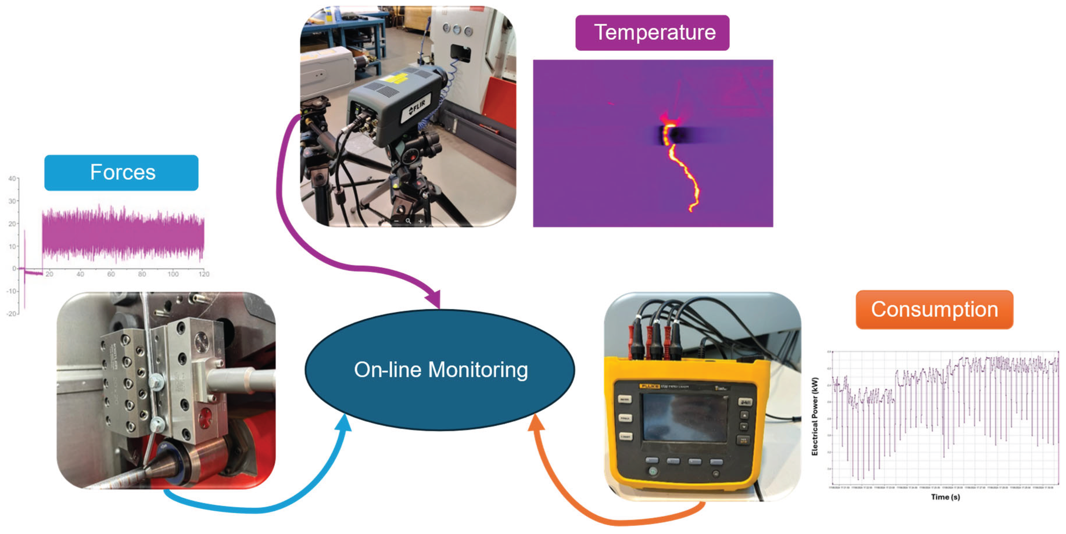
Figure 2.
On-line monitoring variables for the machining analysis.
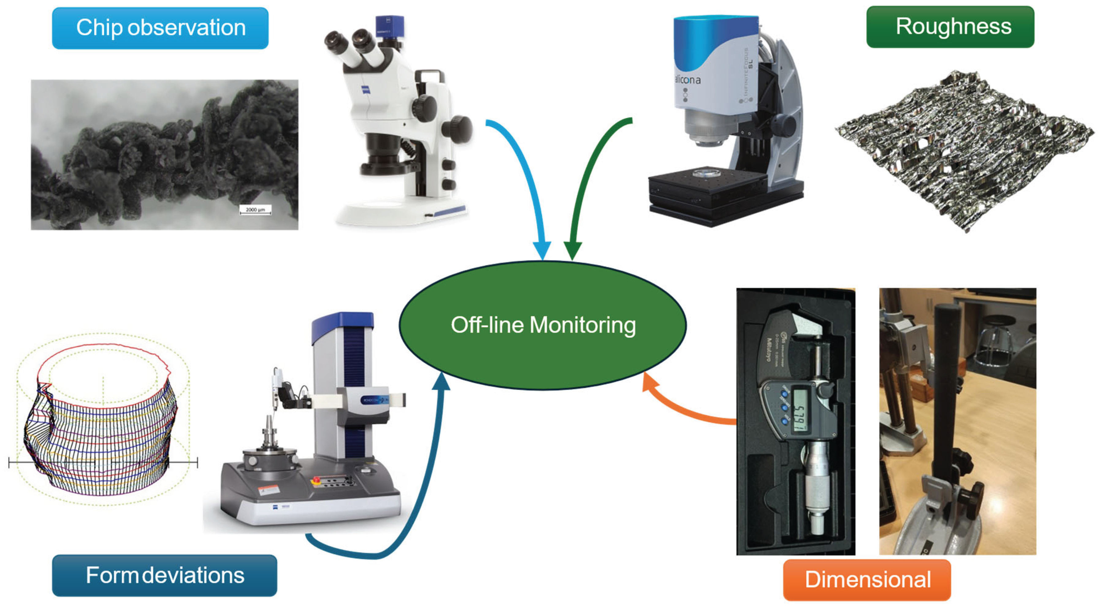
Figure 3.
Cutting temperature in the turning process.
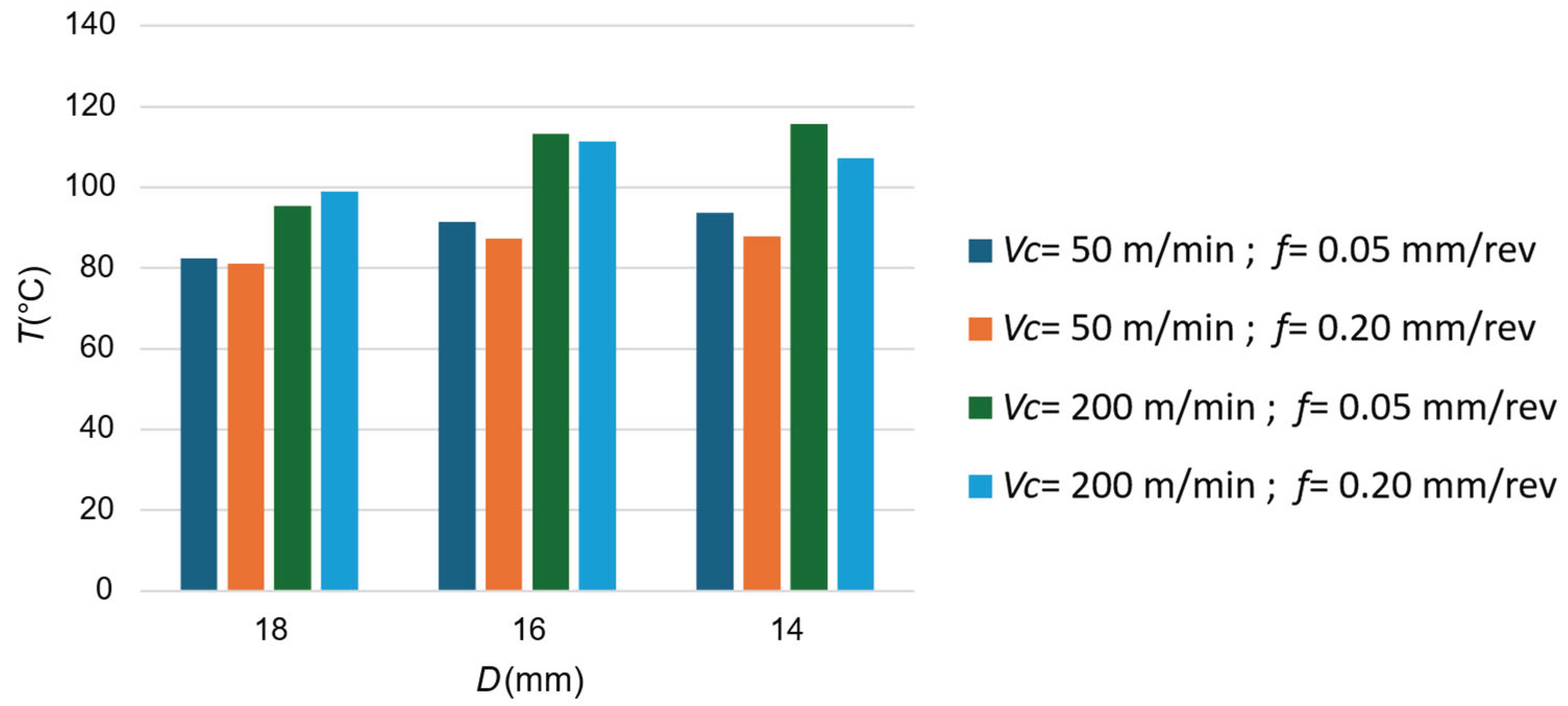
Figure 4.
Forces measured during the cutting process: (a) Passive forces; (b) Cutting forces; (c) Feed forces; (d) Resultant.
Figure 4.
Forces measured during the cutting process: (a) Passive forces; (b) Cutting forces; (c) Feed forces; (d) Resultant.
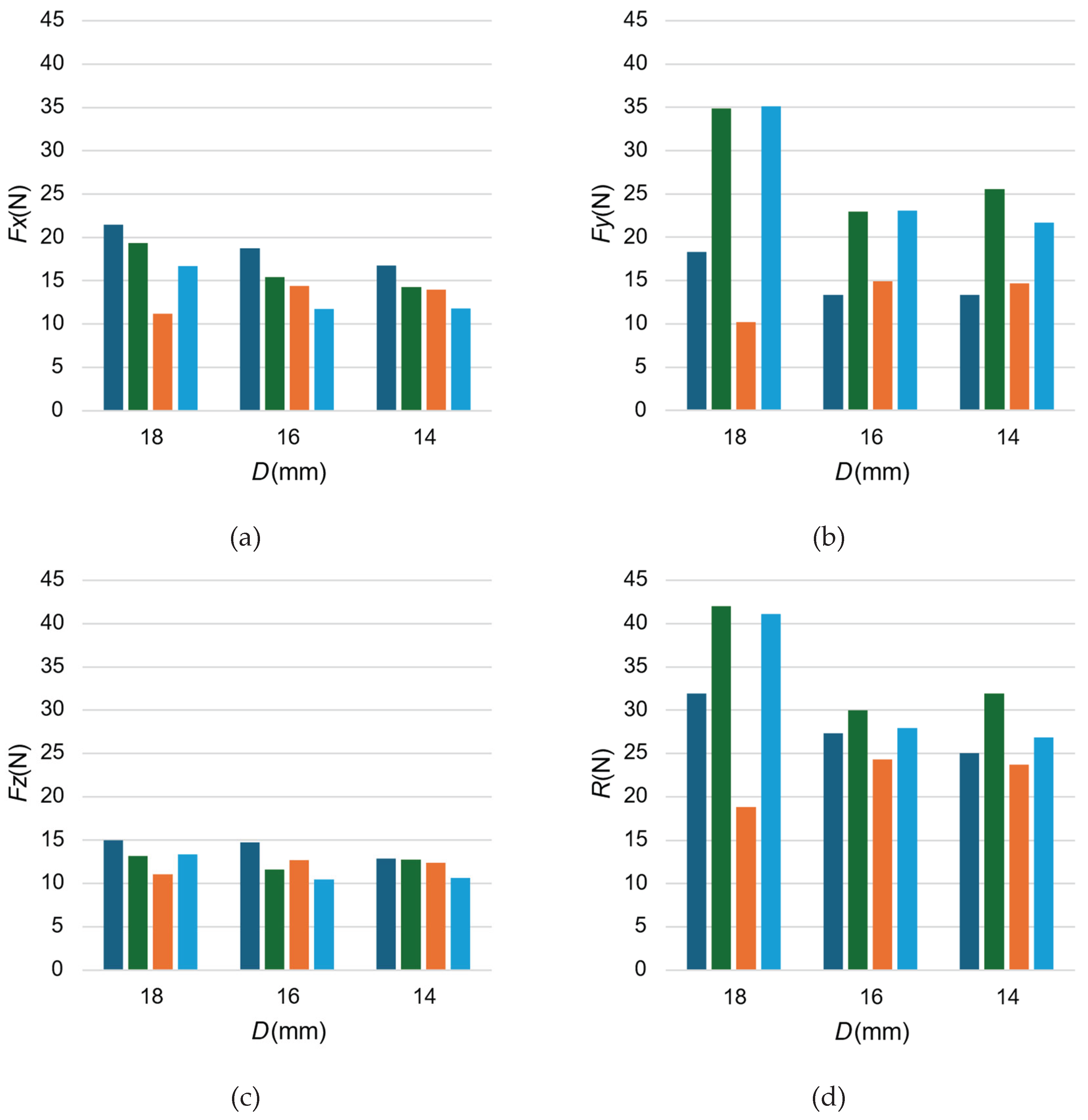
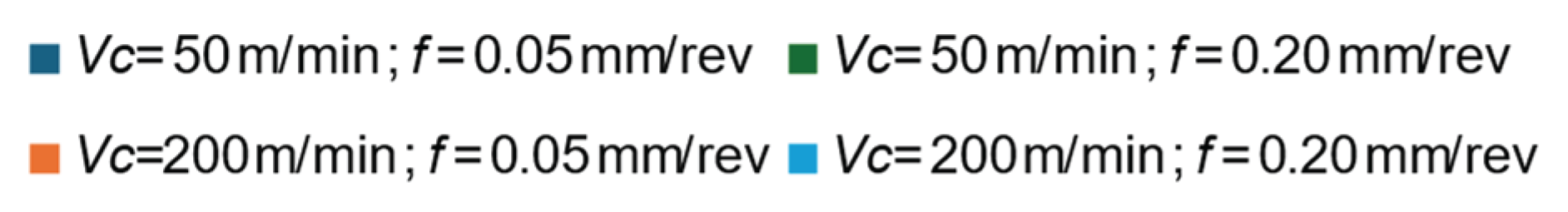
Figure 5.
Electric measurements in the cutting process: (a) Active Pover; (b) Energy consumption.
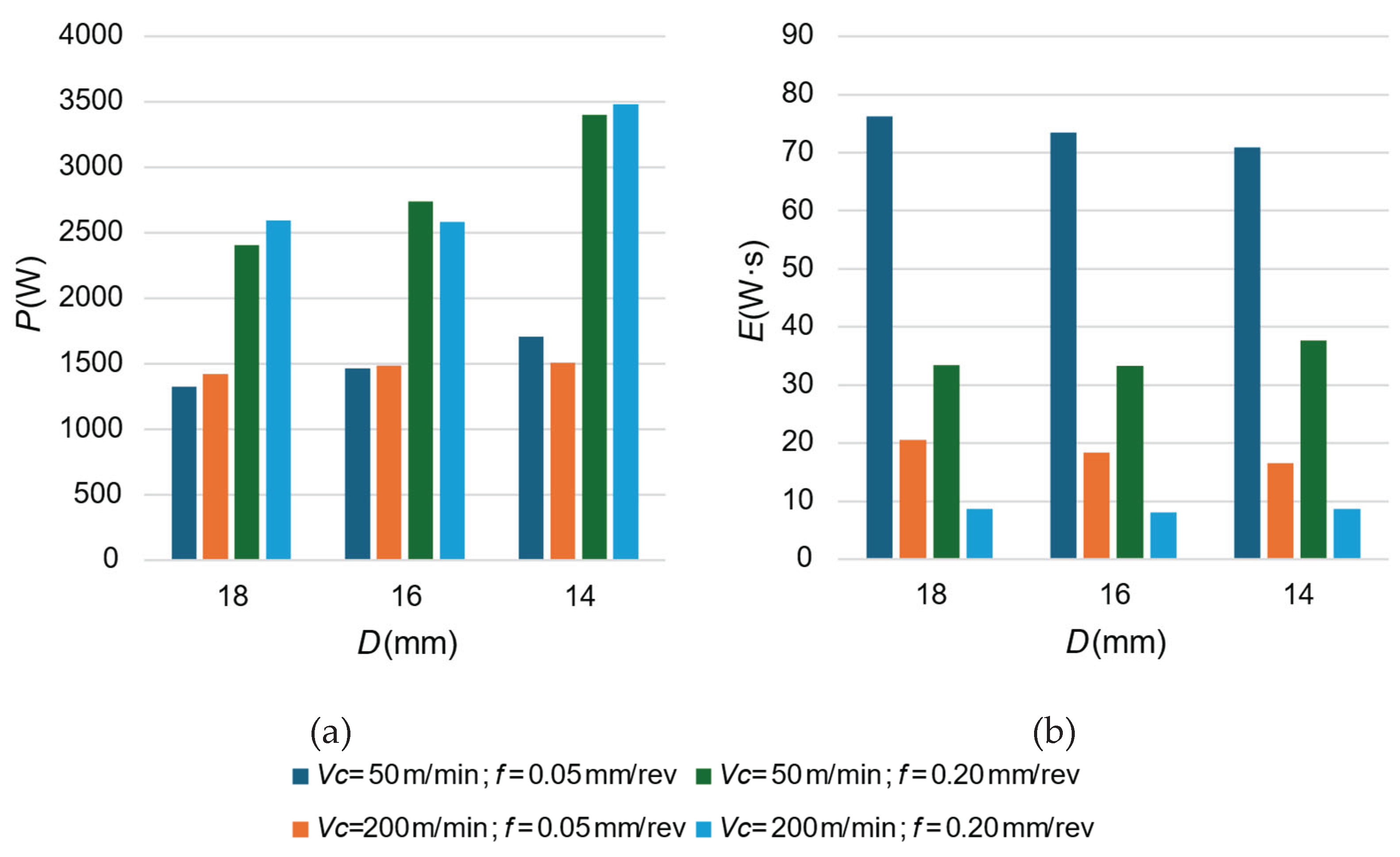
Figure 6.
Chip morphology obtained under different cutting parameters: (a) Active Pover; (b) Energy consumption.
Figure 6.
Chip morphology obtained under different cutting parameters: (a) Active Pover; (b) Energy consumption.
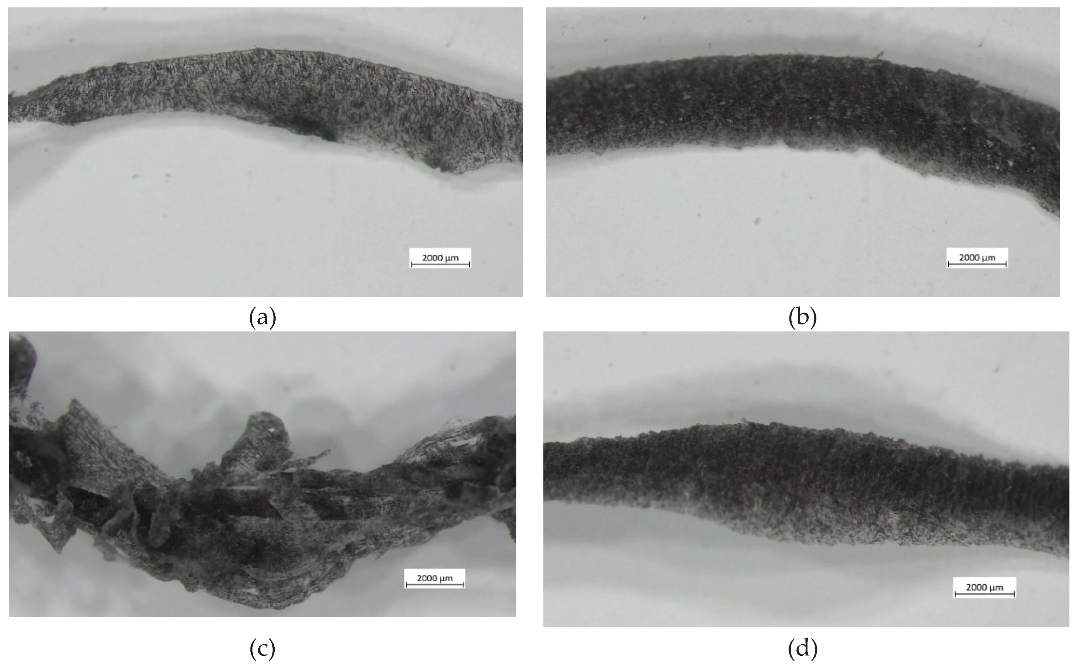
Figure 7.
Dimensional errors measured for the samples as a function of vc, f and D: (a) D = 18 mm; (b) D = 16 mm; (c) D = 14 mm.
Figure 7.
Dimensional errors measured for the samples as a function of vc, f and D: (a) D = 18 mm; (b) D = 16 mm; (c) D = 14 mm.
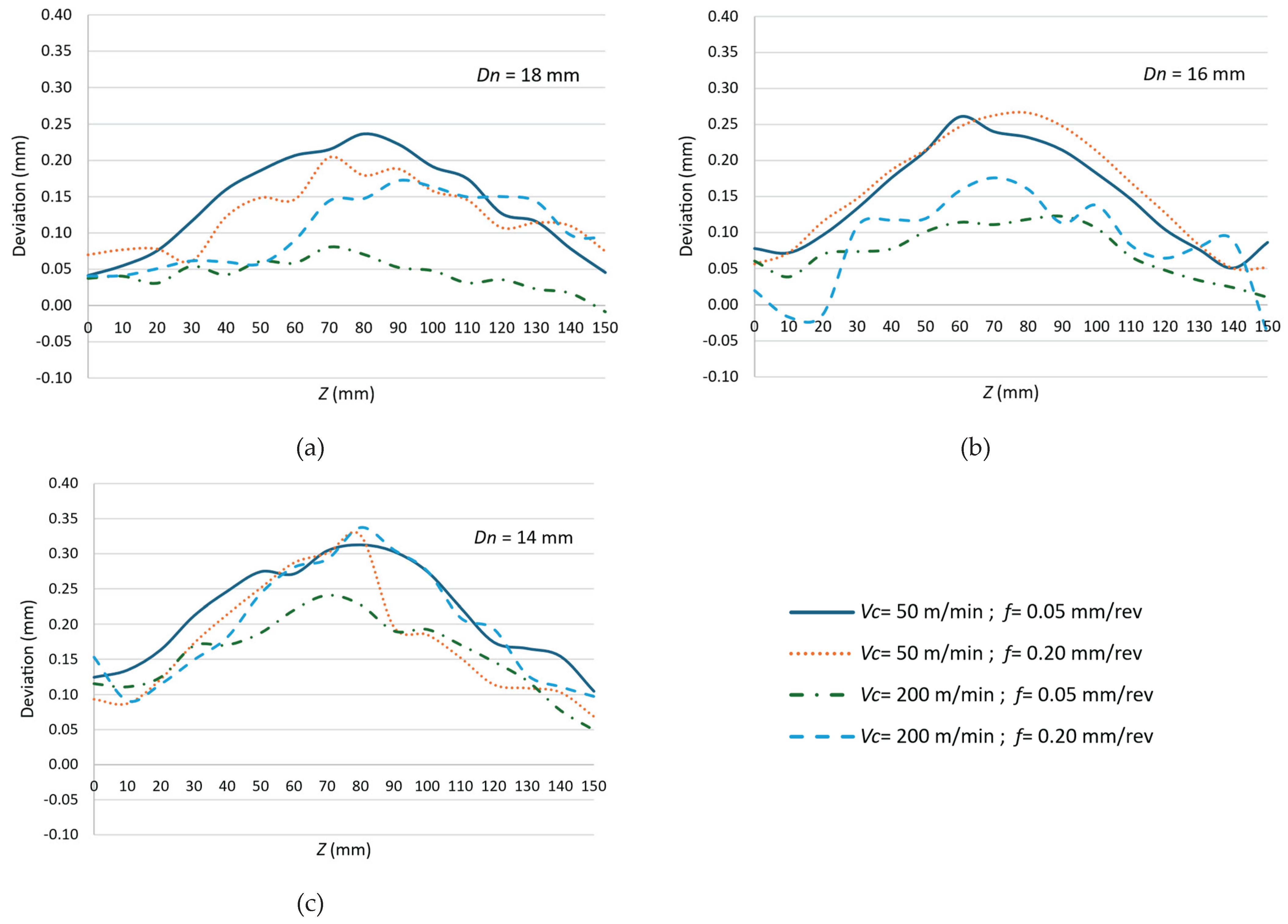
Figure 8.
Normalized deflection of the turned surface as a function of axial position.
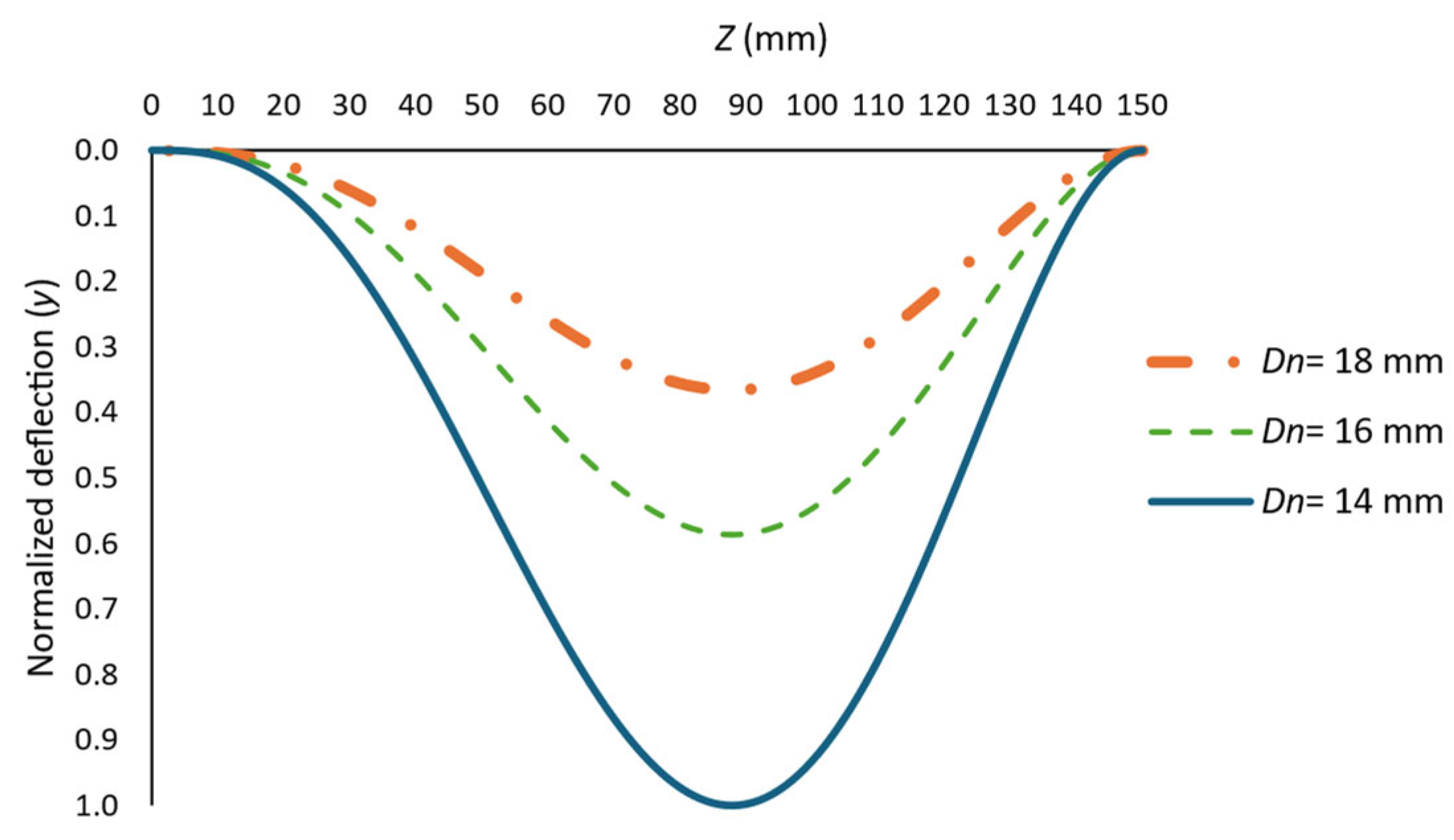
Figure 9.
Macrogeometrical deviations obtained in turned samples as a function of vc, f and D, and printed samples by FFF as a function of layer thickness: (a) Roundness; (b) Straightness; (c) Cylindricity.
Figure 9.
Macrogeometrical deviations obtained in turned samples as a function of vc, f and D, and printed samples by FFF as a function of layer thickness: (a) Roundness; (b) Straightness; (c) Cylindricity.
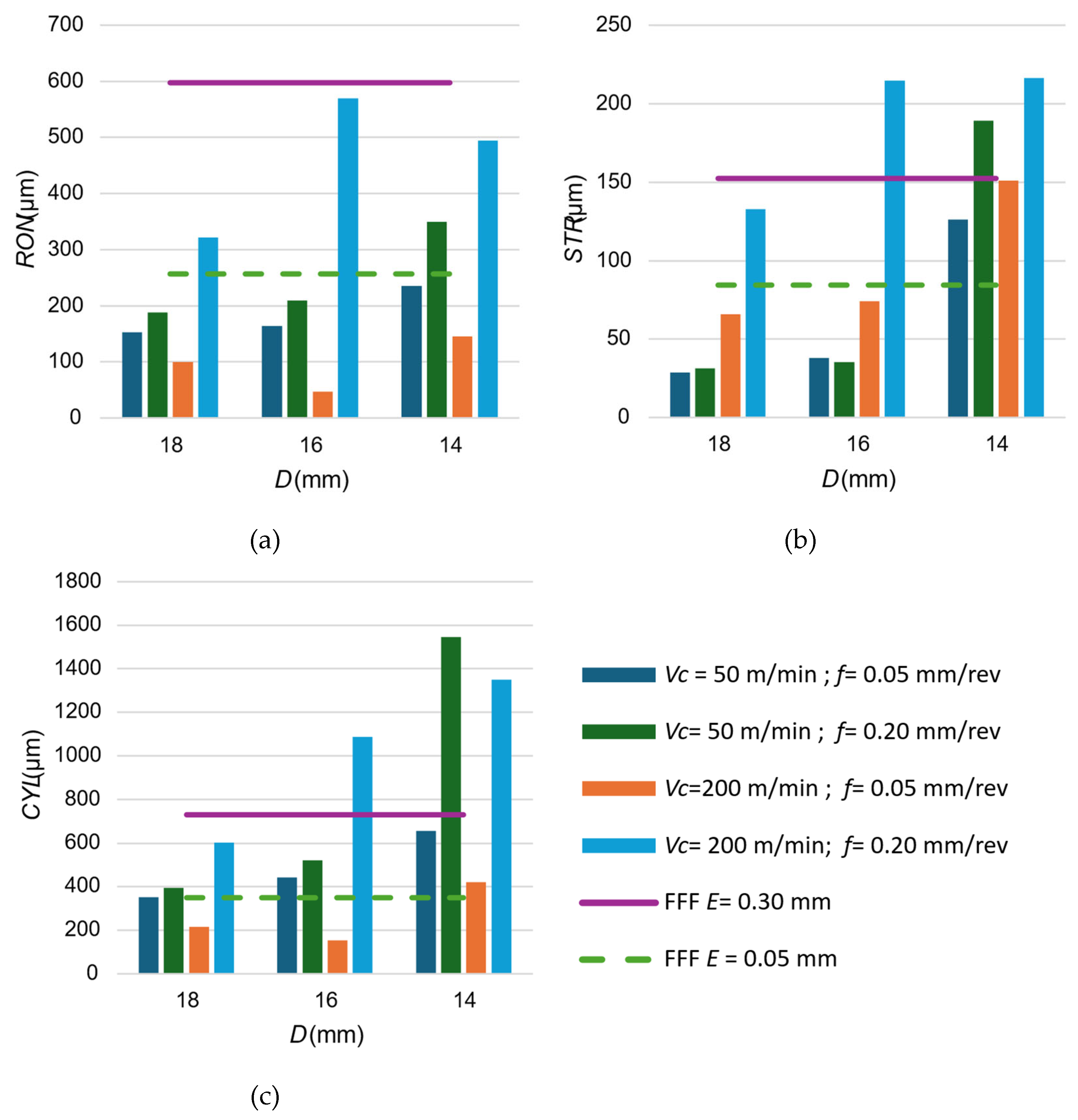
Figure 10.
Surface Roughness obtained in turned samples as a function of vc, f and D, and printed samples by FFF as a function of layer thickness: (a) Sa; (b) Sz.
Figure 10.
Surface Roughness obtained in turned samples as a function of vc, f and D, and printed samples by FFF as a function of layer thickness: (a) Sa; (b) Sz.
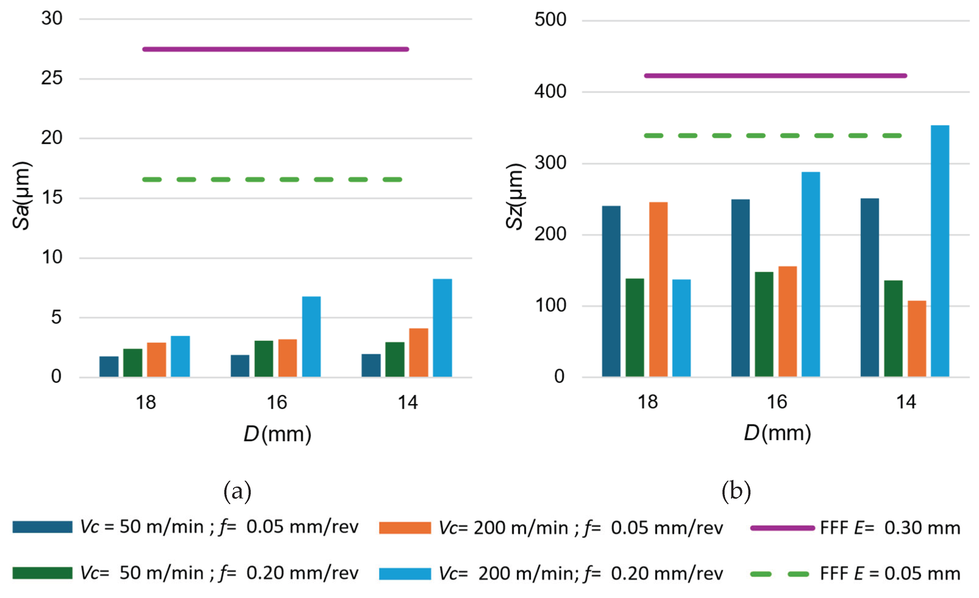
Figure 11.
Surface topography obtained in machined and printed samples.


Table 1.
FFF manufacturing settings for PLA-CF Specimens.
| Manufacturing setting | Value |
|---|---|
| Extrusion temperature | 210 °C |
| Heated bed temperature | 80 °C |
| Extrusion speed | 70 mm/s |
| Layer thickness | 0.30-0.05 mm |
| Infill density | 100% |
| Nozzle diameter | 0.40 mm |
Table 2.
Tool geometry data for turning operations.
| Cutting tool geometry | Value |
|---|---|
| Relief angle (α) | 7 ° |
| Cutting edge angle (β) | 66 ° |
| Rake angle (γ) | 17 ° |
| Major cutting edge angle (κr) | 62.5 ° |
| Insert include angle (ε) | 55 ° |
| Nose radius | 0.8 mm |
Table 3.
Cutting parameter values for turning operations.
| vc (m/min) | f (mm/rev) | ap (mm) |
|---|---|---|
| 50-200 | 0.05-0.20 | 1 |
Table 4.
Rxy resultant and shear stress values in the interlayer FFF sample during turning operation.
Table 4.
Rxy resultant and shear stress values in the interlayer FFF sample during turning operation.
| D (mm) | Rxy (N) | σ (MPa) |
|---|---|---|
| 18 | 46.30 | 0.182 |
| 16 | 39.84 | 0.198 |
| 14 | 36.51 | 0.237 |
Disclaimer/Publisher’s Note: The statements, opinions and data contained in all publications are solely those of the individual author(s) and contributor(s) and not of MDPI and/or the editor(s). MDPI and/or the editor(s) disclaim responsibility for any injury to people or property resulting from any ideas, methods, instructions or products referred to in the content. |
© 2025 by the authors. Licensee MDPI, Basel, Switzerland. This article is an open access article distributed under the terms and conditions of the Creative Commons Attribution (CC BY) license (http://creativecommons.org/licenses/by/4.0/).
Copyright: This open access article is published under a Creative Commons CC BY 4.0 license, which permit the free download, distribution, and reuse, provided that the author and preprint are cited in any reuse.


