
Submitted:
12 June 2025
Posted:
13 June 2025
You are already at the latest version
Abstract
This paper presents the design and implementation of a longrange smart home automation system using LoRa (Long Range) technology. The system consists of a transmitter and a receiver circuit that utilize the RYLR896 LoRa (Long Range) module to communicate over a range of 1–2 km, with potential coverage up to 15 km. A push button at the transmitter end triggers signals that are received and acknowledged via an OLED (ORGANIC LIGHT-EMITTING DIODE) display on the receiver side, which also controls an appliance through a relay. Integration with Google Home via the ESP8266 NodeMCU (Node Micro Controller Unit) allows voice-based control, enhancing user accessibility. The use of LoRa (Long Range) ensures reliable, low-power communication suitable for large homes or remote areas, addressing the limitations of conventional Wi-Fi and Bluetooth-based systems. The proposed system demonstrates efficiency, scalability, and real-time responsiveness, making it ideal for modern smart home applications.
Keywords:
Arduino Uno
; ESP8266 NodeMCU (Node Micro Controller Unit)
; Google Home
; Home Automation
; Internet of Things (IoT)
; LoRa
; Long Range Communication
; OLED (ORGANIC LIGHT-EMITTING DIODE) Display
; Push Button
; RYLR896
; Smart Home
1. Introduction
The rapid evolution of the Internet of Things (IoT) has revolutionized the way we interact with our environment, particularly within the domain of smart homes. The integration of Internet of Things (IoT) in domestic settings has enabled the automation and remote control of household appliances, lighting, security systems, and energy management— enhancing convenience, efficiency, and security in everyday life. However, a major limitation in existing home automation systems lies in the communication technologies used—such as Wi-Fi, Bluetooth, and Zigbee—which tend to be effective only in small, localized environments [1]. These technologies suffer from drawbacks like limited range, high power consumption, network congestion, and signal attenuation due to obstacles like walls or floors, making them less suitable for large residences, multi-storey buildings, or rural areas.
In response to these challenges, LoRa (Long Range) (Long Range) technology has emerged as a powerful wireless communication protocol tailored for low-power, longdistance, and low-bandwidth applications [1]. Operating in the sub-GHz frequency bands, LoRa (Long Range) (Long Range) can support communication ranges up to 15 kilometers in open outdoor environments and 1–2 kilometers in urban or semiobstructed settings. Its ability to transmit data over long distances with minimal energy usage makes it highly suitable for applications in remote monitoring, smart agriculture, environmental sensing, and home automation.
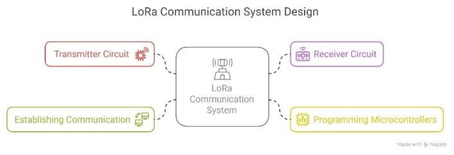
This research paper presents the design and implementation of an advanced smart home automation system using LoRa (Long Range) communication, focused on longrange, reliable, and low-energy data transmission. The system is composed of two main circuits: a transmitter circuit and a receiver circuit. The transmitter module includes a push button, which, when pressed, initiates a signal using the LoRa (Long Range) RYLR896 module. The receiver module, also equipped with the LoRa (Long Range) module, listens for the incoming signal and upon reception, performs two key actions: it displays a confirmation message on a 0.96-inch OLED (ORGANIC LIGHT-EMITTING DIODE) display and triggers a relay to switch off an appliance, such as an AC-powered light.
To ensure compatibility with modern smart home ecosystems, the system is also integrated with Google Home, allowing voice-activated commands and cloudbased automation routines. Key components used in the project include the Arduino Uno, ESP8266 NodeMCU (Node Micro Controller Unit), 5V relay module, AC plug circuit, LEDs, resistors, and the Arduino IDE for programming and interfacing the microcontrollers.
The primary motivation behind this project is to bridge the communication gap in areas where conventional networks like Wi-Fi are ineffective or impractical due to distance, terrain, or infrastructure limitations. The solution aims to offer a scalable, energy-efficient, and costeffective alternative for home automation systems, especially in rural settings or large residential areas where centralized Wi-Fi coverage is either inconsistent or nonexistent.
By combining LoRa’s exceptional range and low power consumption with the ease-of-use and interactivity of platforms like Google Home, the proposed system demonstrates a new direction for smart home innovation— focusing on accessibility, reliability, and practicality.
Key Features
- I.
- Dual-Circuit Architecture
The system comprises a transmitter circuit with a push button and a receiver circuit with a relay and OLED (ORGANIC LIGHT-EMITTING DIODE) display, enabling seamless wireless communication and device control [2].
- II.
- Long-range wireless communication
The system uses LoRa (Long Range) RYLR896 modules capable of transmitting data over distances ranging from 1 to 15 kilometers, making it suitable for large homes, remote areas, and agricultural fields.
- III.
- Low power consumption
LoRa (Long Range) technology ensures energy efficiency, allowing components to function for extended periods without frequent recharging or high energy demand.
- IV.
- Instant Device Control
Pressing the transmitter button sends a signal to the receiver, which activates or deactivates appliances using a 5V relay.
- V.
- Offline Operation
Core functions between transmitter and receiver work without internet, ensuring reliable control even in remote areas.
- VI.
- Google Home Integration
Through ESP8266 NodeMCU (Node Micro Controller Unit), the system supports voice commands and automation via Google Home, enhancing smart control.
- VII.
- Real-Time Feedback
The 0.96” OLED (ORGANIC LIGHT-EMITTING DIODE) display on the receiver provides immediate feedback upon signal reception, confirming successful communication.
2. Implementation
This system integrates wireless communication, manual control, and automated relay switching using two microcontrollers: Arduino UNO and ESP8266 NodeMCU (Node Micro Controller Unit), both interfaced with the REYAX RYLR998 LoRa (Long Range) module for long-distance data transmission. Let us explore both circuits and their implementation.
- I.
- Transmitter Circuit (Based on Arduino UNO)
The Arduino UNO serves as the transmitter, controlling the relays based on button inputs and sending the data to the ESP8266 via the LoRa (Long Range) module.
- i.
- RYLR998 LoRa (Long Range) Module: REYAX Enables long-range wireless communication between the Arduino and NodeMCU (Node Micro Controller Unit). Operates over Universal Asynchronous Receiver-Transmitter (UART) using TX and RX pins.
- ii.
- Four Push Buttons (S1 to S4): Each button is assigned to a respective relay. When pressed, the button triggers a HIGH/LOW signal that is processed by the Arduino.
- iii.
- 5V Relay Module: Used to switch AC appliances like bulbs. The relays are triggered via digital pins (D2 to D5) on the Arduino.
- iv.
- Visual Feedback: A basic LED with a 1kΩ resistor is connected to pin A3 for indicating transmission status.
- v.
- Power Management: All modules are powered using a +5V and GND rail.
- iv.
- Serial Communication: The LoRa (Long Range) module communicates with the Arduino via software serial to avoid conflicts with the USB serial port.
- II.
- Receiver Circuit (Based on ESP8266 NodeMCU (Node Micro Controller Unit)) The ESP8266 NodeMCU (Node Micro Controller Unit) acts as the receiver, decoding LoRa (Long Range) commands to reflect button states and displaying status on an OLED (ORGANIC LIGHT-EMITTING DIODE) display.
- i.
- REYAX RYLR998 LoRa (Long Range) Module:
Communicates with Arduino UNO over LoRa (Long Range) protocol to receive control commands wirelessly
- ii.
- OLED (ORGANIC LIGHT-EMITTING DIODE) Display:
Connected via I2C (SCL and SDA), it displays the status of each appliance, making the system user-friendly and interactive
- iii.
- Five Push Buttons:
These provide manual override capability for switching appliances locally. One extra STATUS button is included for general-purpose feedback or test commands.
- iv.
- Status LED:
Glows based on received data or internal logic to indicate connectivity and command execution
- v.
- Power LED:
Shows whether the NodeMCU (Node Micro Controller Unit) is powered, aiding in debugging and monitoring.
- vi.
- Proper Pull-Up Resistors:
Ensures clean signals are transmitted from switches.
- vii.
- Power Supply:
NodeMCU (Node Micro Controller Unit) runs on 3.3V and components like LoRa (Long Range) module and buttons are powered using regulated 3.3V and 5V lines.
- III.
-
Working
- When any button (S1–S4) on the Arduino side is pressed, the corresponding command is transmitted via the LoRa (Long Range) module.
- The ESP8266 NodeMCU (Node Micro Controller Unit) receives the signal, decodes the command, and toggles the status LED and updates the OLED (ORGANIC LIGHT-EMITTING DIODE) screen accordingly.
- The user can manually control the relays via the local buttons on the NodeMCU (Node Micro Controller Unit) side as well.
- The system can operate reliably across long
- distances, thanks to LoRa’s high range and low power capabilities.
- This two-way setup allows robust home automation, even in environments with limited Wi-Fi or Bluetooth coverage.
3. Methodology
The first step in the project involved designing the transmitter circuit, as shown in Figure 1. A LoRa (Long Range) module, such as the Dragino 915 MHz, was chosen for its long-range communication capabilities. This module was interfaced with a microcontroller, typically an Arduino or ESP32, to manage the signal transmission. A push button was connected to the microcontroller, allowing the user to initiate data transmission manually. When the button is pressed, it sends a signal to the microcontroller, which in turn triggers the LoRa (Long Range) module to transmit the predefined data. The microcontroller is programmed to detect the push button press through its digital input pins and to control the LoRa (Long Range) module via digital I/O connections.
The second phase focused on the receiver circuit design, which is illustrated in Figure 2. A similar LoRa (Long Range) module, operating at the same frequency (915 MHz), was configured to receive the transmitted signal. The microcontroller on the receiver side listens for incoming data from the LoRa (Long Range) module and processes it upon receipt. Based on the specific command received (such as turning off a device), the microcontroller activates a relay or a transistor to perform the required action. Additionally, an LCD or OLED (ORGANIC LIGHT-EMITTING DIODE) display is incorporated into the circuit to provide real-time visual feedback to the user, displaying messages like “Signal Received” or “Device Off,” depending on the situation.
Next, both microcontrollers—transmitter and receiver—were programmed to manage their respective tasks, with the overall workflow between them depicted in Figure 3. The transmitter microcontroller is continuously monitoring the push button state. When a press is detected, it sends a specific signal via the LoRa (Long Range) module. On the other side, the receiver microcontroller is programmed to constantly listen for incoming transmissions. When the signal is received, it interprets the command, activates the relay or transistor accordingly, and updates the display with the corresponding message to notify the user of the system’s status. Finally, to establish reliable communication, both LoRa (Long Range) modules were configured to operate on the same frequency, with identical communication parameters such as the data rate and spreading factor. Ensuring that both modules share these settings was crucial for the accurate transmission and reception of data between the transmitter and receiver circuits.
4. Results and Discussion
The proposed Internet of Things (IoT) -based Smart Home Automation System using LoRa (Long Range) represents a transformative shift in how smart technologies can be implemented in both urban and remote environments. Unlike traditional systems that are heavily reliant on WiFi or Bluetooth—which are limited by range, scalability, and power inefficiency—this project utilizes LoRa (Long Range) (Long Range) technology, enabling communication over distances of up to 15 kilometers while consuming minimal power. This is a game-changer for rural and agricultural regions, large estates, and off-grid areas where internet access is unreliable or unavailable [1].
The system’s ability to control household appliances remotely, monitor activity in real time, and respond to voice commands via Google Home integration significantly improves user convenience, especially for the elderly or individuals with physical limitations. This opens new possibilities for inclusive smart living, making home automation more accessible and empowering for all demographics.
Beyond individual homes, the project’s scalable and modular design can be extended to commercial buildings, farms, warehouses, or community infrastructure [2]. The use of energy-efficient components, such as the ESP8266 NodeMCU (Node Micro Controller Unit), OLED (ORGANIC LIGHT-EMITTING DIODE) displays, and 5V relays, supports a sustainable approach to automation that reduces unnecessary power consumption and allows for low-maintenance operation.
Moreover, the inclusion of dual circuit architecture—with a transmitter and receiver—ensures robust and secure communication across various nodes. The system’s flexibility allows for easy integration of additional sensors for temperature, humidity, or gas detection, further enhancing safety and control.
In the future, by integrating with advanced microcontrollers like LPC2148, the system can be upgraded to handle real-time data processing, edge computing, and improved hardware interfacing, making it suitable for more complex applications. This paves the way for automated scheduling, predictive maintenance, and AI-driven decision making within the home environment.
Ultimately, the anticipated impact of this project lies in its potential to democratize smart home technology. By offering a cost-effective, energy-efficient, and longrange solution, it breaks traditional barriers of entry, encouraging widespread adoption across varied geographical and economic settings. The project is wellaligned with future trends in Internet of Things (IoT), sustainability, and human-centered design, promising to shape the next generation of intelligent, adaptive living spaces.
5. Future Add On’s and Further Development
- The system’s modularity enables upgrades like LPC2148 integration for real-time, low-latency appliance control.
- A custom mobile app can provide remote access, realtime alerts, and energy usage statistics.
- Voice assistant support (Google Home, Alexa) allows hands-free commands for daily convenience.
- Sensor integration (Passive Infrared Sensor, DHT11, gas) enables automation based on motion, temperature, or gas leaks.
- Two-way LoRa (Long Range) communication with acknowledgments ensures reliable control and device feedback.
- OTA firmware updates can fix bugs or add features without needing physical access.
- Cloud dashboards (via Firebase/Node-RED) offer remote monitoring, scheduling, and analytics.
- Together, these add-ons build a smart, scalable system ideal for modern homes and remote facilities.
Author Contributions
All three student authors contributed equally to the implementation, experimentation, and manuscript drafting. The mentor provided supervision, technical guidance, and critical revisions to the manuscript. All authors reviewed and approved the final manuscript.
Funding
Not applicable.
Data Availability Statement
Not applicable.
Acknowledgments
The authors would like to thank their mentors and colleagues at RV College of Engineering for their valuable support and guidance during this research.
Conflicts of Interest
Not applicable.
List of Abbreviations
| ABBREVIATION | EXPANSION |
| AC | Alternating Current |
| AI/ML | Artificial Intelligence / Machine Learning |
| Arduino | Arduino Uno (microcontroller platform) |
| ESP8266 | Node Micro Controller Unit (NodeMCU) |
| GPIO | General Purpose Input/Output |
| I2C | Inter-Integrated Circuit |
| IoT | Internet of Things |
| LCD | Liquid Crystal Display |
| LED | Light Emitting Diode |
| LoRa | Long Range |
| LoRaWAN | Long Range Wide Area Network |
| NodeMCU | Node Micro Controller Unit |
| OLED | Organic Light-Emitting Diode |
| PIR | Passive Infrared Sensor |
| SCL/SDA | Serial Clock/Serial Data (I2C pins) |
| TX/RX | Transmit/Receive (serial communication) |
| UART | Universal Asynchronous Receiver-Transmitter |
References
- Chen Zhoung, Feasibility of LoRa (Long Range) for Smart Home: Real Time and Coverage Considerations, 2024. [CrossRef]
- Aneesh Pradeep, Implementation of a LoRa-based Home Monitoring System with ESP32 Gateway, 2023.
- Jihen Souifi, Smart Home Architecture based on LoRa (Long Range) and LoRaWAN Networking Protocol, 2020. [CrossRef]
- Sarah Opipah, Prototype Design of Smart Home System Base on LoRa, 2020. [CrossRef]
- Tutun Juhana, The Design of Application for Smart Home Base on LoRa, 2019. [CrossRef]
Figure 1.
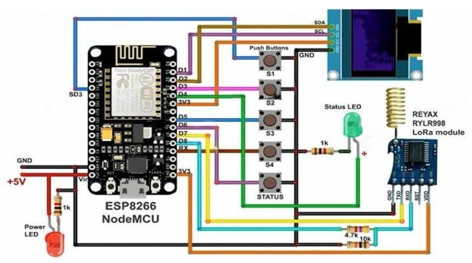
Figure 2.

Figure 3.
Disclaimer/Publisher’s Note: The statements, opinions and data contained in all publications are solely those of the individual author(s) and contributor(s) and not of MDPI and/or the editor(s). MDPI and/or the editor(s) disclaim responsibility for any injury to people or property resulting from any ideas, methods, instructions or products referred to in the content. |
© 2025 by the authors. Licensee MDPI, Basel, Switzerland. This article is an open access article distributed under the terms and conditions of the Creative Commons Attribution (CC BY) license (http://creativecommons.org/licenses/by/4.0/).
Copyright: This open access article is published under a Creative Commons CC BY 4.0 license, which permit the free download, distribution, and reuse, provided that the author and preprint are cited in any reuse.


