Submitted:
04 June 2025
Posted:
04 June 2025
You are already at the latest version
Abstract
The experimental and computational characterization of a cold model prototype designed to test the electromagnetic properties of a new RFQ (Radio Frequency Quadrupole) cavity is reported. This cavity is intended to be an essential part of a compact, high-gradient proton accelerator for medical purposes. The RFQ design employs a novel RF power-coupler injection solution. One common way to couple the RF power in proton RFQs has been the use of loop-couplers inserted into the mid-section of the RFQ lobe sections. This technique has demonstrated to be reliable and effective but introduces a significant perturbation into the lobe that can be more noticeable when dealing with compact structures. We propose a RF injection scheme by using direct transition from a coaxial cable to the RFQ by connecting the inner coaxial conductor to the RFQ vane body. As a consequence, the lobe geometry is not perturbed and the transversal electrical fields are directly excited through the vanes. Moreover, by using a pair of such couplers connected to opposite vanes at a given transversal plane of the RFQ, it is also possible to excite the desired quadrupolar TE210 mode avoiding the excitation of dipolar TE110 modes. The resonances corresponding to different RFQ modes have been characterized, and the dependence of the amplitude of the modes on the relative phase of the field injected through the RF power ports has been demonstrated both by measurements and simulations.
Keywords:
radio frequency quadrupole
; linear particle accelerators
; proton beams
; RF measurements
; resonance
1. Introduction
The Radio Frequency Quadrupole (RFQ) is the most used injection structure in linear particle accelerators for massive particles like protons and heavier ions. The reason being that it's the only structure that can accept a continuous flow of low-energy particles beam (keV) and accelerate them into the MeV range. In this structure, a single RF field provides all the different functionalities required for proton acceleration.
Simultaneously with the acceleration, the RF field confines the particles and bunches the continuous beam into a collection of macroscopic packets. The design principles were first presented by Kapchinski and Tepliakov in 1969 [1] and the first operational RFQ was demonstrated at LANL in 1980 [2]. Geometrically, it’s a resonant cavity with cylindrical symmetry divided in 4 lobes or vanes resembling a clover-like figure (Figure 1). This structure enhances the excitation of the TE210 mode with quadrupole symmetry providing a continuous, alternating quadrupole along the RFQ axis. Due to the shape of the section, the magnetic field dominates at the lobes and the electric field dominates in the central channel, where the particles would travel and accelerate. This provides a pure electrical focusing, not dependent on the particle velocity, well suited for massive particles like protons.
Typical proton RFQs use a frequency in the range from 300 to 400 MHz such as, for instance, the 324 MHz FETS RFQ at RAL [3] or the 352.2 MHz LINAC4 RFQ developed at CERN as a part of the LHC injector [4]. The use of higher frequencies allows to reduce the RFQ size at the expense of acceleration efficiency. In 2016, CERN built the first compact proton RFQ at 750 MHz [5]. The final RFQ for our project is also intended to work at 750MHz and provide proton acceleration from 30keV to 4,5 MeV in a compact structure 1.5 m long structure [6,7]. As a proof of concept, to check the design procedure and to study mechanical feasibility a cold-model was built, which is a shorter version (0.5 m) intended to work at low power (mW) and without a vacuum (Figure 2).
The paper is divided into two main sections, plus a concluding discussion section. Section Materials and Methods is devoted to present the RFQ cold model we have designed and tested for this study and its electromagnetic eigenmode analysis. The Results section reports the experimental results. In particular, the new power injection scheme is presented, including aspects as power combination and mode excitation or avoidance with the help of the relative phase between the injected signals.
2. Materials and Methods
The RFQ design process has to fulfil some specific requirements from the EM point of view. The TE210-like quadrupolar mode has to be excited at the operating frequency, maximizing the quality factor Q and keeping away in frequency undesired modes, as it is the case of dipolar modes such as TE110. A common way to couple the RF power in proton RFQs has been the use of loop-couplers inserted into the mid-section of the RFQ lobes. This technique has demonstrated to be reliable and effective but introduces a significant perturbation into the lobe that can be more noticeable when dealing with compact structures. We propose a double symmetrical RF injection scheme using direct transition from the coaxial cable to the RFQ by connecting the inner coaxial conductor into the RFQ vane body, as it can be seen in Figure 3.
As a result, the insertion of metallic parts in the lobe itself are avoided, resulting in minimized lobe field perturbations. Note that, in such way, the transversal electrical fields are directly exited trough the vanes. Moreover, by combining two couplers connected to opposed vanes at a given transversal plane of the RFQ it is also possible to excite quadrupolar mode avoiding the dipolar modes. This coupling avoids introducing objects in the cavity that would perturb the designed fields. From an electromagnetic point of view, it can be pictured as a transition from a TEM mode in the coaxial to a TE mode on the cavity (Figure 4).
A section of a compact RFQ has been designed and manufactured to serve as a cold model. This is a proof-of-concept realistic model intended to be tested under small-signal conditions. When analyzing the RFQ resonances using Eigenmode analysis, two first modes appear corresponding to quasi-degenerated dipolar modes (TE110) along the Y and X axis (Figure 5 and Figure 6).
The modes are not at the same frequency because the symmetry is not perfect, and the signal injection is made in the X axis. Neither of these modes are appropriate for confining the beam, as they only act in one of the axis.
The third mode (TE210) is the one with quadrupole symmetry (Figure 7), which acts in both axis and has the correct shape for confining the beam. It alternates focusing periods in the X and Y direction along the length of the RFQ, providing a purely electrical focus. At higher frequencies, one can find the same three modes (dipolar Y, dipolar X and quadrupolar) repeated as harmonics. In these modes the field intensity changes as length increases, becoming zero at the nodes. The most problematic modes are the harmonics of the dipolar modes, which lay really close to the main quadrupolar mode, and can overlap with it, especially if the structure is long. The reason being that the frequency of the harmonics decreases as length increases. The coupling solution can be tested through frequency domain simulation, injecting the signal from the coaxial cables to the RFQ through the ports implementing a direct coaxial-like electric coupling (Figure 3).
3. Results
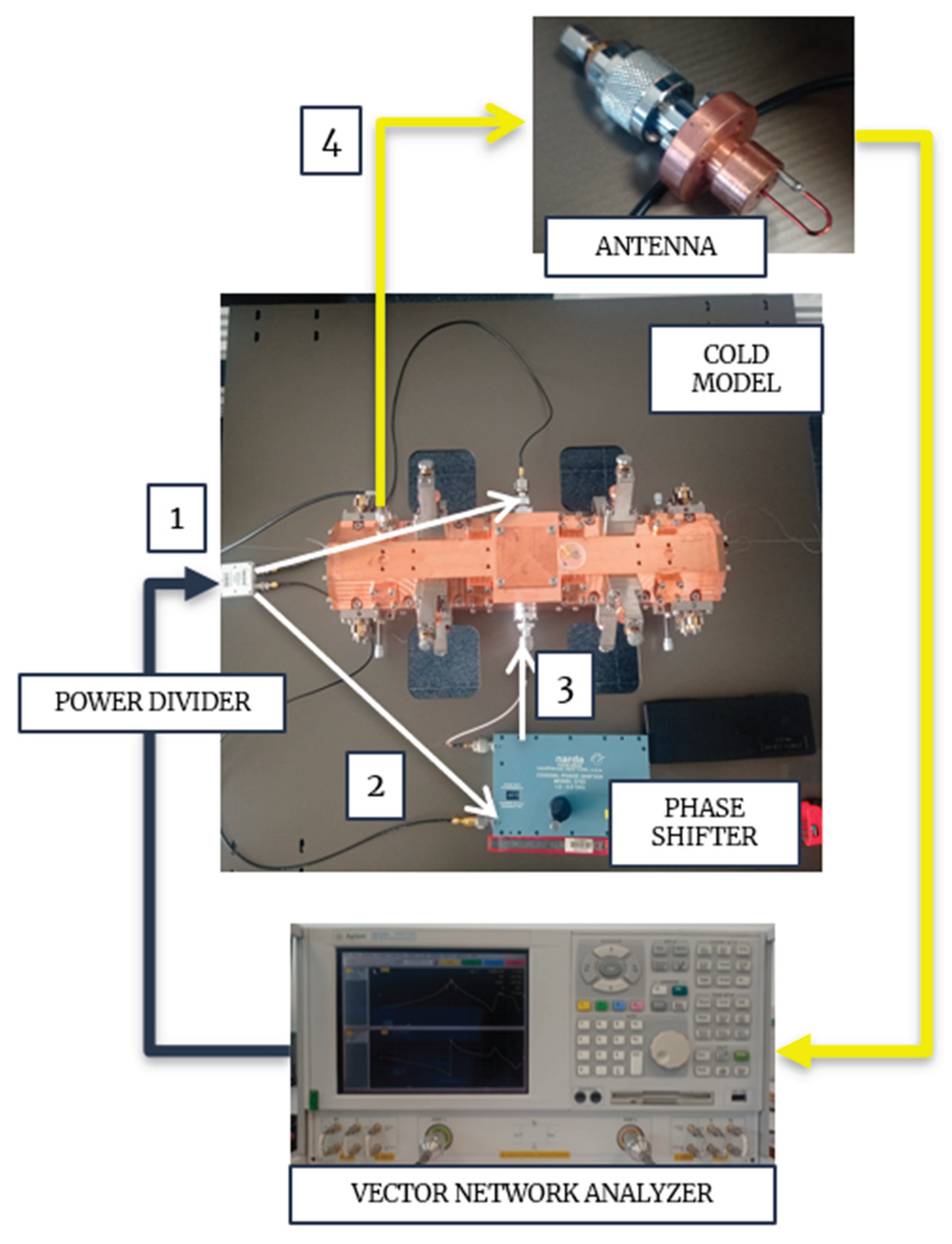
In order to check the appearance of the different modes, as well as their excitation amplitude, one could arrange a setup like in Figure 8. The signal from a VNA (Vector Network Analyzer) is divided in two signals with equal amplitude. One of them goes through a variable phase shifter which allows to control the relative phase between the two RFQ input ports and the other is connected directly. Finally, the signal is picked employing an antenna located near the beginning of the structure. This picked signal goes back to the VNA.
For the first measurement, the phase difference is kept at 0, and a frequency sweep is performed. The transmission coefficient as a function of frequency is plotted in Figure 10. As in the simulations, the first two modes to appear (dipolar modes TE110) are quasi-degenerated. Afterwards, it comes the predominant mode (the quadrupolar TE210 mode). And finally, the harmonics of those three modes are observed.
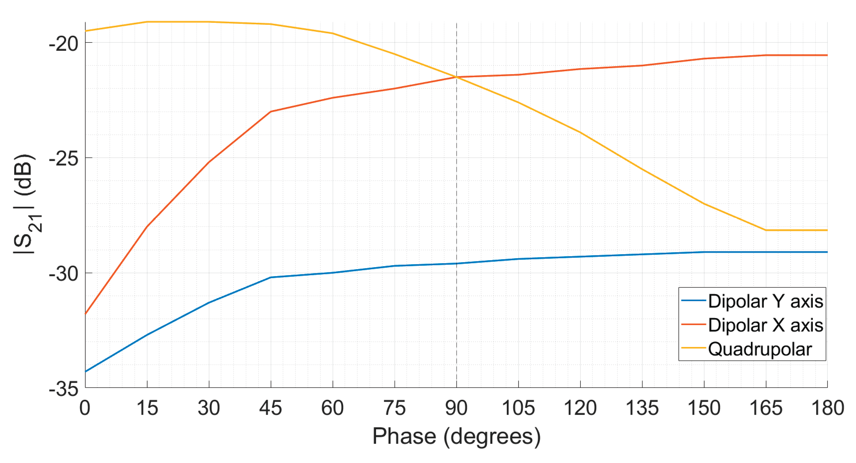
As there are two ports to inject the signal, a degree of freedom exists which is the relative phase between them. If the phase is the same, the symmetry with the quadrupolar mode (Figure 7) is maximum. However, as the phase difference increases, the coupling with the dipolar modes (Figure 5 and 6), in which they are completely out of phase, increases. This result is found experimentally in Figure 9. Moreover, halfway between being in phase and out of phase, at 90◦, the excitation amplitude of the Dipolar mode X and the Quadrupolar mode become equal.
Figure 9.
Absolute value of the transmission coefficient in dB as a function of the normalized frequency.
Figure 9.
Absolute value of the transmission coefficient in dB as a function of the normalized frequency.
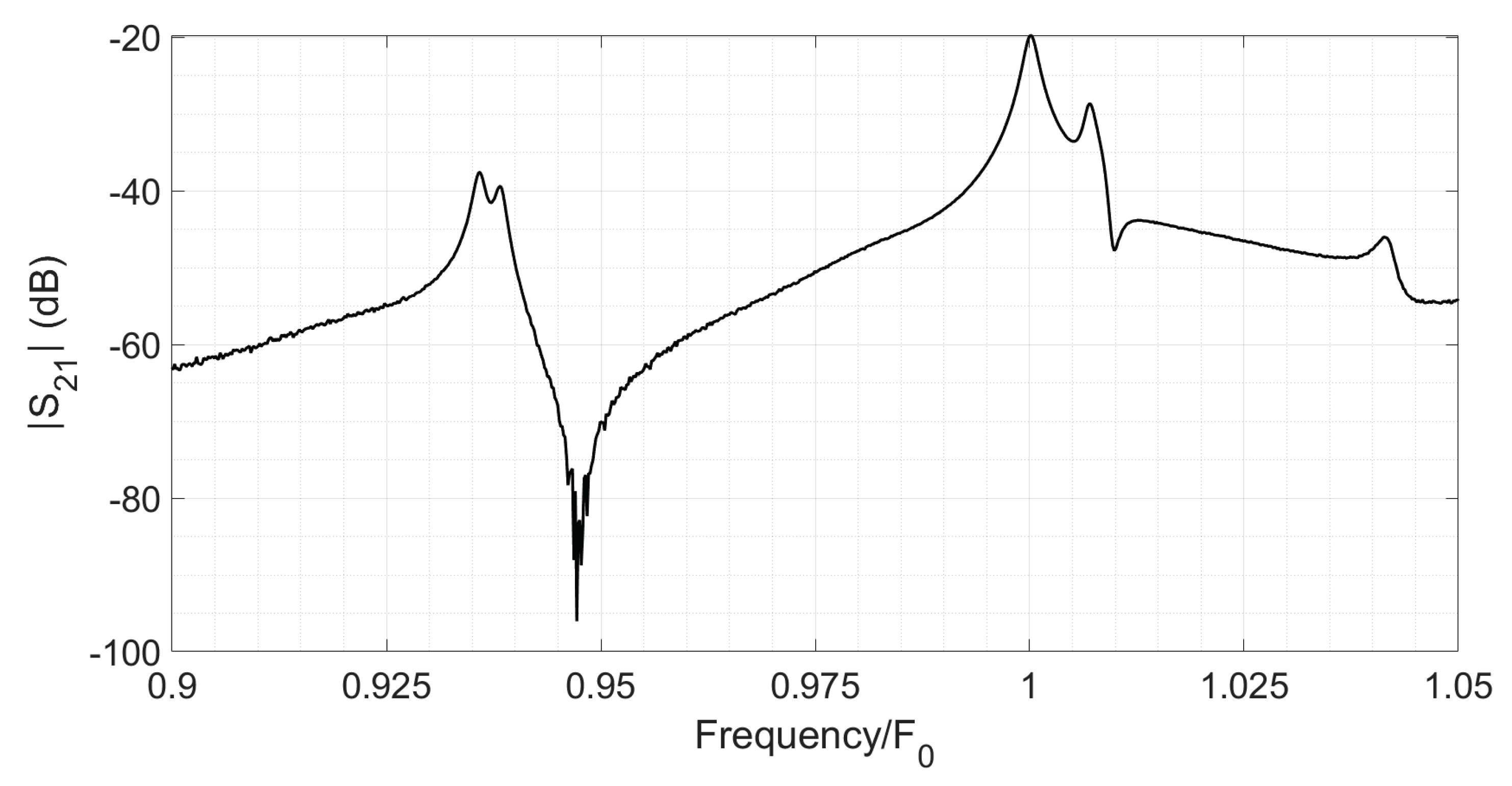
Figure 10.
Excitation amplitude of the Dipolar and Quadrupolar modes as a function of the relative phases between the two input ports.
Figure 10.
Excitation amplitude of the Dipolar and Quadrupolar modes as a function of the relative phases between the two input ports.
4. Discussion
Building an operational RFQ cavity for proton particle acceleration involves an intricate electromagnetic design of its geometry and excitation ports. The use of computational parametric models, as well as the manufacturing of low power prototypes is essential to predicting the future behavior of the final structure. In the work presented, some experiments were performed in order to characterize the EM properties of the cavity. The spectrum of a typical RFQ has been reproduced, consisting of two spurious TE110 dipolar modes, one fundamental TE210 quadrupolar mode and its harmonics. The prototype employs an innovative approach which delivers the power via electric coupling. It consists of 2 coaxial-like entrances from opposite sides of the RFQ, whose relative phase can be adjusted in order to maximize the excitation amplitude of the desired TE210 mode and simultaneously minimize the excitation amplitude of the TE110 dipolar modes. This fact perfectly matches the field symmetries observed in the eigenmode simulation. It has been demonstrated, both by measurements and simulations, that this new proposed power injection design is able to excite the required resonant fields in the RFQ for appropriate simultaneous beam focusing, bunching and acceleration, avoiding the insertion of metallic obstacles into the RFQ lobes.
Author Contributions
Conceptualization, J.P. and M.L.; methodology, J.F.; software, I.A.; validation, M.L., J.F. and I.A.; formal analysis, V.E; investigation, M.L. and J.P; writing—original draft preparation, M.L.; writing—review and editing, V.E.; supervision, J.P.; project administration, J.F.; funding acquisition, V.E. All authors have read and agreed to the published version of the manuscript.
Funding
This research was funded by the Basque Government, grant number IT1533-22 and grant number KK-2022/00026. It is also supported by the Spanish Research Agency, grant PID2023-148792OB-I00. The APC was funded by the Basque Government, grant number IT1533-22.
Data Availability Statement
The data presented in this study will be made available by the authors on request.
Conflicts of Interest
The authors declare no conflicts of interest
References
- Kapchinskii, I.M.; Teplyakov, V.A. A linear ion accelerator with spatially uniform hard focusing. Prib. Tekh. Eksp. 1970, 1970.2, 19–22. [Google Scholar]
- Ahearne, J.T.; Jameso, R.A. RFQ is alive and well… Atom Los Alamos Laboratory 1980 17.
- Letchford, A. et al.; Status report on the RAL front end test stand. 2007 IEEE Particle Accelerator Conference (PAC), 2007, 1634–1636. [CrossRef]
- Arnaudon, L. et al. The Linac4 Project at CERN. International Particle Accelerators Conference (IPAC), 2011, 900–902. https://jacow.org/IPAC2011/papers/TUOAA03.pdf.
- Lombardi, A. et al.; Beam Dynamics in a High Frequency RFQ. International Particle Accelerators Conference (IPAC), 2015, 2408–2412. [CrossRef]
- Feuchtwanger, J.; et al. New Generation Compact Linear Accelerator for Low-Current, Low-Energy Multiple Applications. Applied Sciences 2022, 12(9), 4118. [Google Scholar] [CrossRef]
- Portilla, J. et al;. EM and Thermo-Mechanical Analysis and Design of a Compact-RFQ. IEEE MTT-S International Conference on Numerical Electromagnetic and Multiphysics Modeling and Optimization (NEMO) 2022, 1-3. [CrossRef]
Figure 1.
Radio Frequency Quadrupole (RFQ) designed and built at IZPILab Beam Laboratory: (a) RFQ cold model clover-like transversal section: (a) Description of what is contained in the first panel; (b) Equivalent lumped component approximation.
Figure 1.
Radio Frequency Quadrupole (RFQ) designed and built at IZPILab Beam Laboratory: (a) RFQ cold model clover-like transversal section: (a) Description of what is contained in the first panel; (b) Equivalent lumped component approximation.
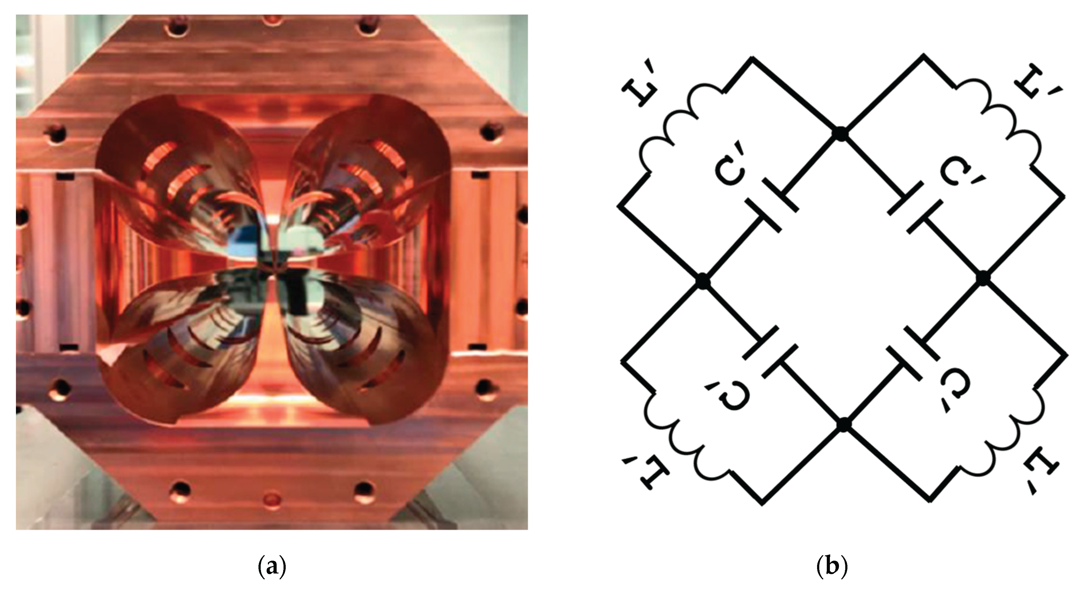
Figure 2.
Photo of the RFQ cold-model prototype at IZPILab Beam Laboratory UPV/EHU.
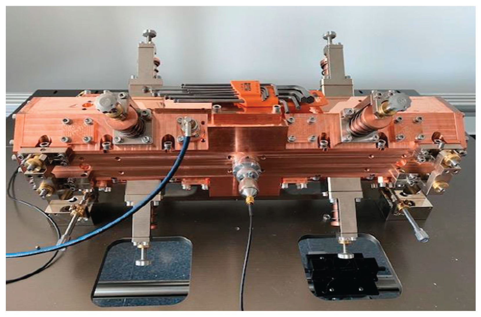
Figure 3.
Power coupling system based on loop antenna coupling (left) and direct coaxial electrical coupling (right).
Figure 3.
Power coupling system based on loop antenna coupling (left) and direct coaxial electrical coupling (right).
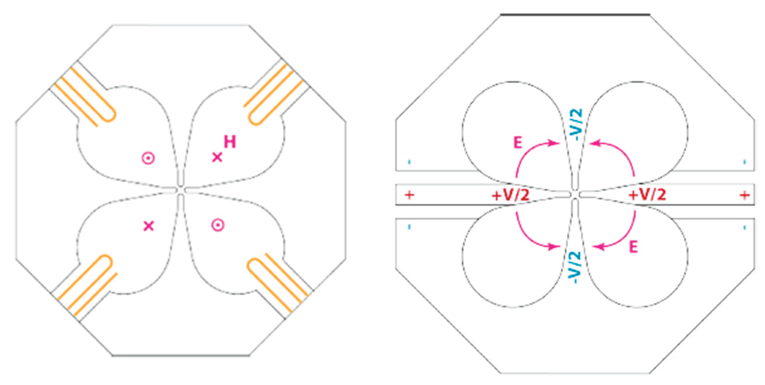
Figure 4.
Magnetic vector field H at different positions from inner coax (a), middle (b) to RFQ transition (c).
Figure 4.
Magnetic vector field H at different positions from inner coax (a), middle (b) to RFQ transition (c).
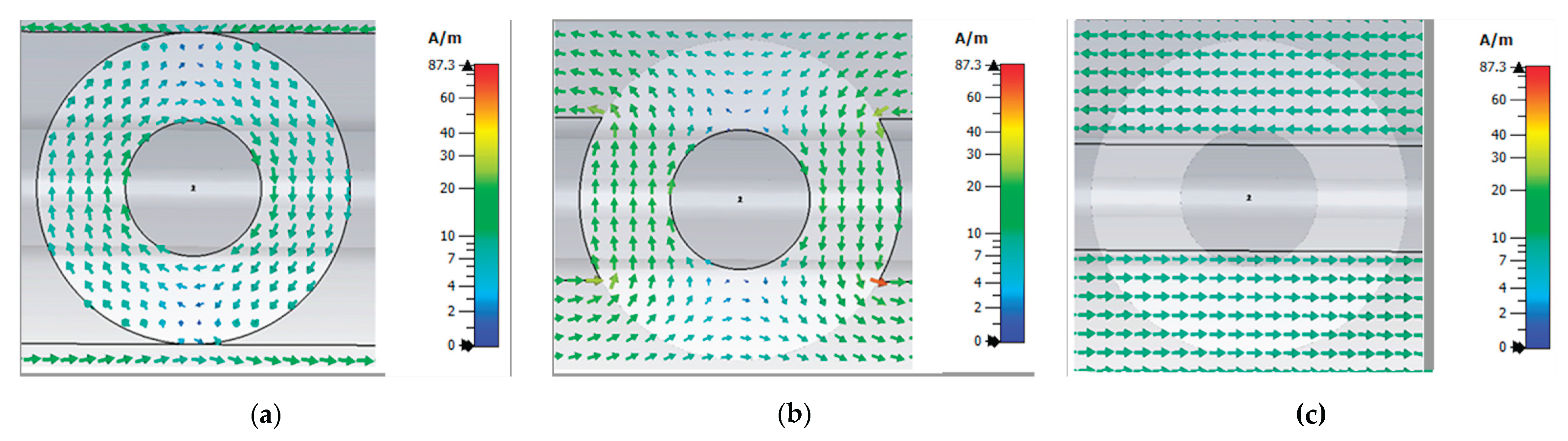
Figure 5.
Electric field vector for Dipole mode aligned Y axis. Cross section of the cold model. Snapshots at t=0 and t=T/2.
Figure 5.
Electric field vector for Dipole mode aligned Y axis. Cross section of the cold model. Snapshots at t=0 and t=T/2.
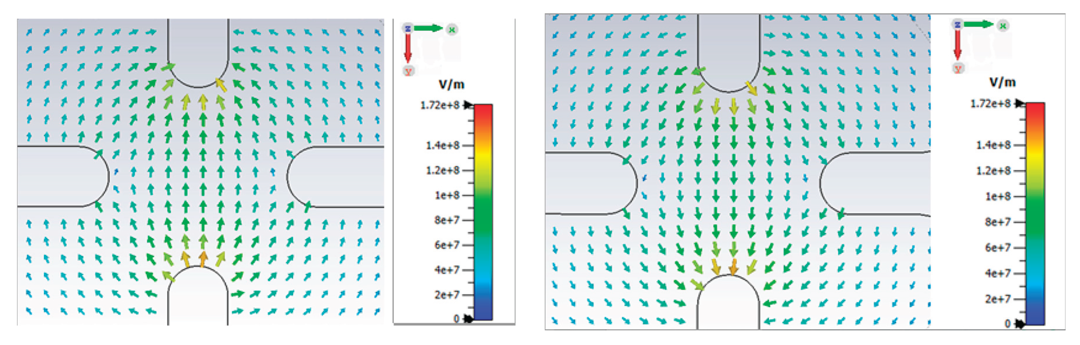
Figure 6.
Electric field vector for Dipole mode X. Cross section of the cold model. Snapshots at t=0 and t=T/2.
Figure 6.
Electric field vector for Dipole mode X. Cross section of the cold model. Snapshots at t=0 and t=T/2.
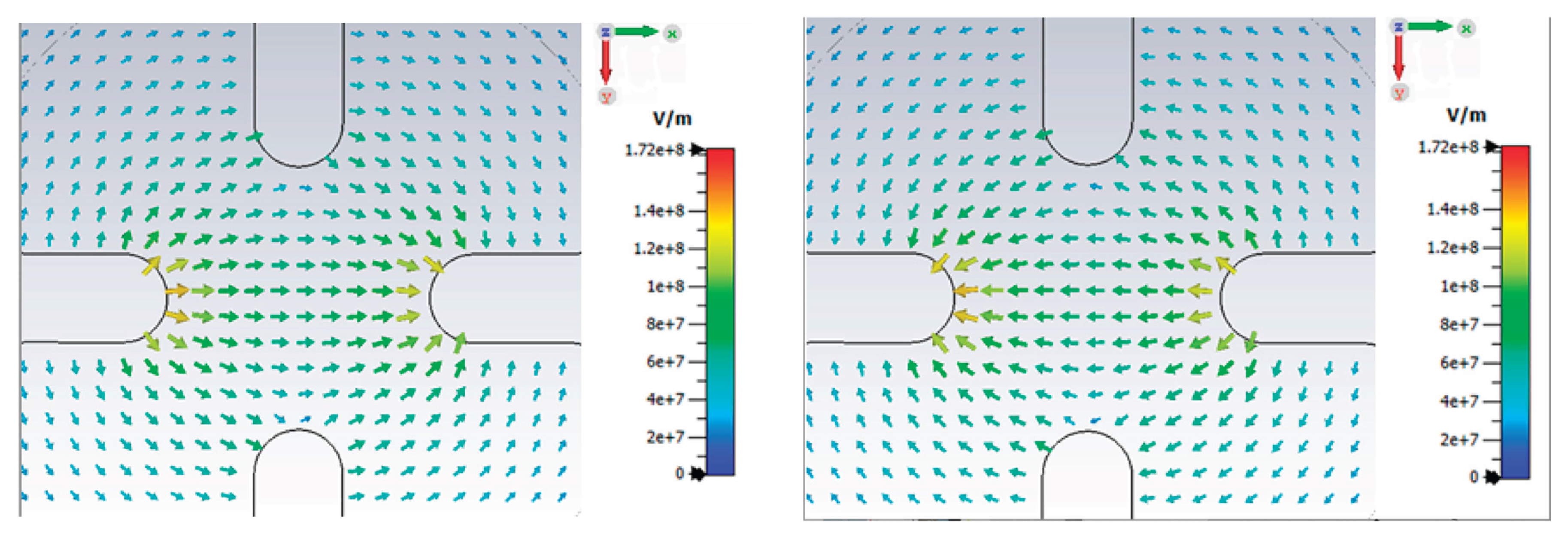
Figure 7.
Electric field vector for Quadrupolar mode. Cross section of the cold model. Snapshots at t=0 and t=T/2.
Figure 7.
Electric field vector for Quadrupolar mode. Cross section of the cold model. Snapshots at t=0 and t=T/2.
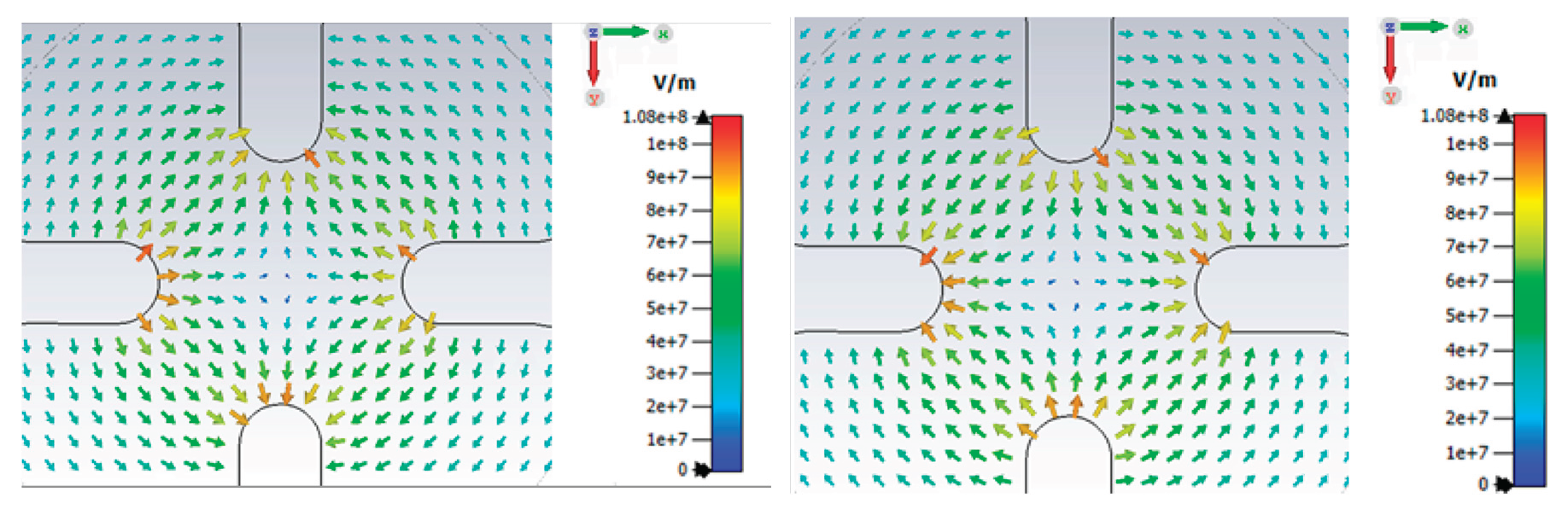
Figure 8.
Setup for the frequency response characterization of the RFQ cold model.
Disclaimer/Publisher’s Note: The statements, opinions and data contained in all publications are solely those of the individual author(s) and contributor(s) and not of MDPI and/or the editor(s). MDPI and/or the editor(s) disclaim responsibility for any injury to people or property resulting from any ideas, methods, instructions or products referred to in the content. |
© 2025 by the authors. Licensee MDPI, Basel, Switzerland. This article is an open access article distributed under the terms and conditions of the Creative Commons Attribution (CC BY) license (http://creativecommons.org/licenses/by/4.0/).
Copyright: This open access article is published under a Creative Commons CC BY 4.0 license, which permit the free download, distribution, and reuse, provided that the author and preprint are cited in any reuse.


