
Submitted:
03 June 2025
Posted:
04 June 2025
You are already at the latest version
Abstract
Extraterrestrial exploration presents unique challenges for robotic systems, where traditional rigid rovers face limitations in stowage volume, traction on unpredictable terrain, and susceptibility to damage. Soft robotics offers promising solutions through bio-inspired designs that can mimic natural locomotion mechanisms. We present an optimised soft spider-inspired jumping robot for extraterrestrial exploration that addresses key challenges in soft robotics: actuation efficiency, controllability, and deployment. Drawing inspiration from spider physiology, particularly their hydraulic extension mechanism, we develop a lightweight limb capable of multi-modal behaviour with significantly reduced energy requirements. Our 3D-printed soft actuator leverages pressure-driven collapse for efficient retraction and pressure-enhanced rapid extension, achieving a power-to-weight ratio of 249 W/kg. The integration of a non-backdriveable clutch mechanism enables the system to hold positions with zero energy expenditure—a critical feature for space applications. Experimental characterisation and a subsequent optimisation methodology across various materials, dimensions, and pressures reveals that the robot can achieve jumping heights of up to 0.92 body lengths. The collapsible nature of the soft limb enables efficient stowage during spacecraft transit, while the integrated pumping system facilitates self-deployment upon arrival. This work demonstrates how biologically-inspired design principles can be effectively applied to develop versatile robotic systems optimised for the unique constraints of extraterrestrial exploration.
Keywords:
soft robotics
; bio-inspired design
; space exploration
; jumping locomotion
; spider-inspired actuators
; hydraulic actuation
; 3D printing
; extraterrestrial robotics
; untethered robots
; TPU actuators
; untethered soft robot
1. Introduction
1.1. Soft Robotics for Extraterrestrial Exploration
There is significant interest in extraterrestrial exploration, particularly directed towards Mars and the moons of Jupiter. This interest in extraterrestrial exploration spans both private and public sectors. Current approaches have utilised rigid rovers for planetary exploration, which have a few critical drawbacks: stowage volume, limited traction on unpredictable terrain, and susceptibility to damage. Ishigami et al. demonstrated the sinking terramechanics of rover wheels interacting with Martian soil [1]. Soft-legged locomotion could help to avoid the issues of wheeled locomotion on complex surfaces like those of Mars [2]. Feng et al. demonstrated a small cubesat-style robot that utilises tendon-driven retraction and soft compliant hinges for deployment, demonstrating the benefits of jumping locomotion on small celestial bodies [3]. The utilisation of jumping on planets with low gravity offers some key energy benefits as large distances can be covered with comparatively less energy to other methods. A clear example of this phenomenon is the transition of the Apollo crew from a walking gait to a hopping gait while on the lunar surface. The prevalent use of pneumatic actuation in soft robots is also well suited to extraterrestrial environments that have lower atmospheric pressure than earth. As highlighted by Ng and Lum [4], untethered soft robots provide a range of potential benefits for exploring other planets.
1.2. The Difficulty of Untethering Soft Robots and the Compromises of Soft Actuation
One of the foundational benefits of soft robots is the ability to mimic natural systems [5,6,7]. The actuation methods prevalent in soft robotics closely mimic those of nature, particularly compared to rigid robots that rely primarily on electromagnetic actuation [8,9]. Despite the similarities between soft actuators and nature, there is a large difference in their respective utilisation of input energy. According to a review of mobile soft robots by Shui et al. soft robots generally have an efficiency of 0.1% [10]. This low reported efficiency can be in part due to ineffective mechanical conversion or the reliance on a multi-stage power conversion train. Energy losses are an important variable in the systems-level design of robots. The gap between the energetic efficiency of terrestrial animals and robots is smaller for rigid robots than it is for soft robots [11,12]. Chun et al. highlight the importance of systems-level design rather than component level design with a bond-graph theory based abstraction [13]. The abstraction by Chun et al. emphasises the need for a holistic approach to soft robot design, considering the entire system rather than individual components, especially in the context of untethered soft robots.
Making untethered soft robots is difficult due to two main factors: (1) dependence on heavy external pneumatic or electric systems [14], and (2) inefficiencies in the design and manufacture of soft actuators. These inefficiencies mean that system design choices for a soft robot are made later in the process. Ideally, the system requirements would inform the rational choice and design of the actuator. This actuator-first approach means there exist only a few untethered jumping soft robots. Tolley et al. built an untethered explosion-driven jumping soft robot capable of directional jumps of 0.6 m [15], but the use of explosives limits the repeatability and operational safety of a soft robot. Other jumping robots, such as the JelloCube created by Li and Rus, demonstrate dynamic bounding movement by using a spring winding and release mechanism to enable rapid actuation [16]. The use of compression springs allows for large jumps but limits the controllability of actuation. These robots demonstrate two approaches to enable dynamic movement and highlight the difficulty in achieving the levels of adaptability exhibited by animals. Such methods of actuation involve a compromise between actuation rates and controllability.
Furthermore, the difficulty of analytically modelling the complex material behaviours and non-linear mechanical responses often renders purely analytical approaches insufficient. As a result, the geometry and material choice for many soft actuators are not optimised for use in an end system. This experimental foundation enables us to develop a practical optimisation methodology informed by system-level requirements rather than being constrained by theoretical limitations.
Considering the constraints of extraterrestrial exploration, such as the inclusion of sensor packages, an untethered robot would need to be able to locomote with a payload. Sayed et al. demonstrate a 10 g sensor payload capable of environmental sensing for extreme environments [17]. To fully actualise the potential benefits of soft robots for space exploration applications, actuation needs to be compact, controllable, and energy efficient.
1.3. Spider Bio-Mechanics Offer a Framework for Efficient Soft Systems
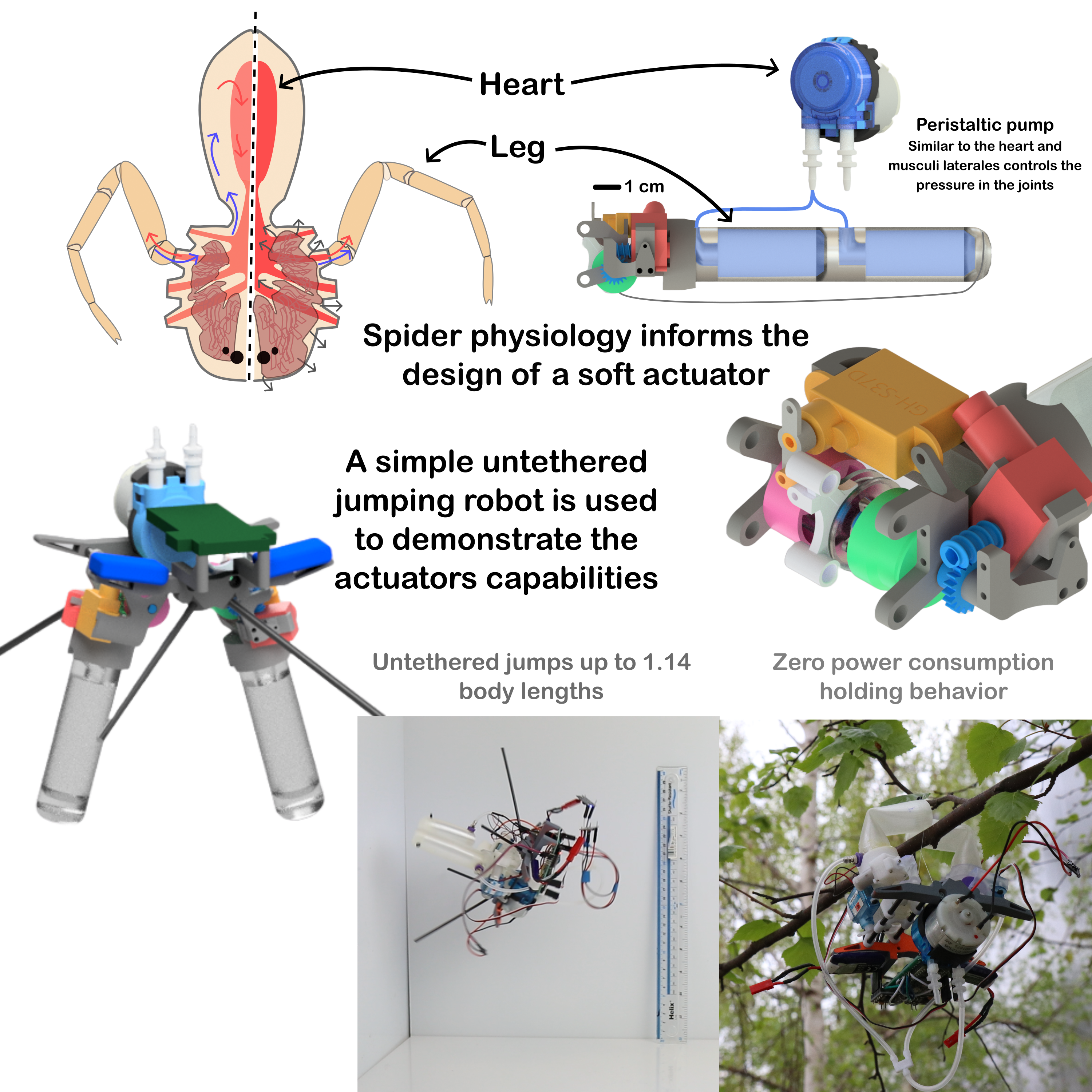
One candidate for the energetic actuation of soft robots is the hydraulic extension mechanism of the Arachnida class. Members of the Arachnida class, generally, lack extensor muscles in their legs [18,19]. Manton and Harding proposed that this hydraulic extension has evolved to allow the limbs to be lightweight, enabling energy-efficient locomotion [20]. These limbs only need a single set of muscles per joint, but —via the utilisation of auxiliary systems —are still fully functional. Species of Arachnida, such as Phidippus regius (commonly known as the jumping spider), exhibit targeted jumping behaviour. The hydraulic extension is driven by muscles in the prosoma (body), which drive hemolymph (blood) into the cavities of the leg (Lacunae, Figure 1a). We use the morphology of the spider as a blueprint for designing our soft robot from the top down, particularly highlighting the use and benefit of hybrid systems.
Göttler et al. have published seminal work on investigating Phidippus regius and the subsequent application of its mechanisms in robotics [21,22,23]. Most notably, a fully 3D printed soft thermoplastic polyurethane (TPU) folding actuator that was capable of jumping [22]. Spider-inspired designs have been used to reduce the internal friction of hydraulic systems, such as the rotary actuator presented by Hepp and Badri-Spröwitz. Landkammer et al. utilised fluidic extension and fluidic muscle contraction to create a rigid spider-inspired limb. Designs that have taken inspiration from but do not as closely mimic arachnida have also been explored [24,25,26,27,28], but the work conducted by Göttler et al. is the only soft spider-inspired actuator to demonstrate jumping behaviour [22].
If a spider wishes to move more dynamically, then it can increase the effective stiffness or spring constant of its limb by tensing muscles in the prosoma, which in turn closes off the blood return path (see Figure 1a). The buildup of pressure inside the limb drives the leg to a straightened position when the flexor muscles are relaxed. Due to the variability of the material stiffness in the limb sections, most of the energy from the fluid is utilised at the point of articulation. The pressurised blood pushes the more flexible membranes of the joint outward, minimising wasted energy trying to extend away from the joint. In non-dynamic cases, the muscles in the prosoma are relaxed and the blood can flow freely back to the body. We draw inspiration from the hybridisation of the systems, by selectively engaging specific features of the system to improve the overall efficiency.
1.4. A Spider-Inspired Thin-Membrane Soft Actuator Which Exhibits Efficient and Dynamic Actuation with Minimal Control Inputs
As described by Section 1.2, there are some core challenges in the design of untethered soft robots, and, as described in Section 1.1, there are some key benefits that the field of soft robotics can offer to extraterrestrial investigation. Intending to mimic the dynamic and efficient movement of natural systems, we seek to combine bio-inspiration with the unique benefits of soft robotics to demonstrate a lightweight, energetic actuation system for space applications.
In this work, we demonstrate the benefits of combining auxiliary systems in an untethered soft robot. As shown by Figure 1, we seek to mimic the key traits of the spider’s movement mechanics. Furthermore, with a focus on space applications, we aim to develop a lightweight, energy-efficient actuation system that can be used in space exploration. Thus, the key design specifications are to: 1.) exhibit control of a joint angle; 2.) exhibit dynamic or rapid extension for jumping; 3.) exhibit low energy holding behaviour; and 4.) be lightweight and volume-efficient. Achieving these specifications, would make the actuator a compelling candidate for space exploration applications compared to purely electro-mechanical or purely soft pneumatic systems.
We refer to the proposed actuator as "JUMPER" - Joint Unbuckling Mechanism with Pressure-enhanced Extension and Retraction, as shown by Figure 1b. The JUMPER actuator consists of two key components: A TPU thin-membrane 3D printed cylinder and a clutched wind and release mechanism.
We designed JUMPER’s soft component to be simple and relatively easy to print. Single joint variants can be easily printed on many desktop 3D printers and can be stacked to create multi-jointed cylinders. The use of Fused Deposition Modelling (FDM) printing allows for rapid prototyping and consistent wall thickness of the cylinder. Printing multi-jointed cylinders such as the one shown by Figure 3 would pose a significant challenge for traditional 3D printing methods, as a result, we utilise the Flex Printer, an open-source 3D printer designed for the development of soft robots [30]. We capitalise on pressure-driven collapse to reduce the effective stiffness of the cylinder, allowing for more efficient retraction.
The reduction of the force to retract the joint, in turn reduces the energy consumption of the retraction mechanism for locomotion or manipulation. During retraction, the geared DC motor draws 0.175 watts of power. The motor itself draws 0.15 watts of power when disconnected from the system, the motor is unable to retract the joint at atmospheric pressure (stalling at around 0.4 watts). As shown by Figure 2a, the force required to retract the joint at vacuum is roughly half that of the force required to retract the joint at atmospheric pressure. Due to the non-backdriveable nature of the worm drive, the cylinder can be at vacuum for retraction, and then pressurised for extension (shown by Figure 2d). This non-backdribeability allows us to exploit the low force of loading under vacuum, and then via pressurisation, jump to the unloading behaviour of the 100 kPa curve. By using the auxiliary pump system, similar to the spiders musculli laterales, a single pump can control the pressure in multiple cylinders or joints. Such a design benefits from upscaling, where a single pump and fluid routing system can enhance the performance of multiple actuators. In instances where multiple joints are required the pressure system can be used to control the behaviour of the limb, as demonstrated in Figure 3. The cylinder itself also serves multiple functions, it is a single-component joint not requiring any bearings or axles, and is simultaneously the structure of the limb.
The retraction system is designed such that it fulfils the criteria we described previously. A small DC motor drives a worm gear, the output of which is attached to a servo-controlled clutch mechanism. The worm gear allows the actuator to hold a position with zero energy expenditure. The ability to hold a position indefinitely enables unique traits, particularly in the context of space exploration. The servo-controlled clutch mechanism draws virtually no energy while idle, when engaged the clutch connects the worm gear to the retraction pulley (see Figure 1) allowing for specific joint angle control for retraction and extension. To achieve dynamic jumping, the pressure in the joint can be increased while retracted, and the clutch disengaged to allow the joint to extend freely and rapidly. The specific rates of actuation across various cylinder materials and diameters is shown by the Supplementary Material.
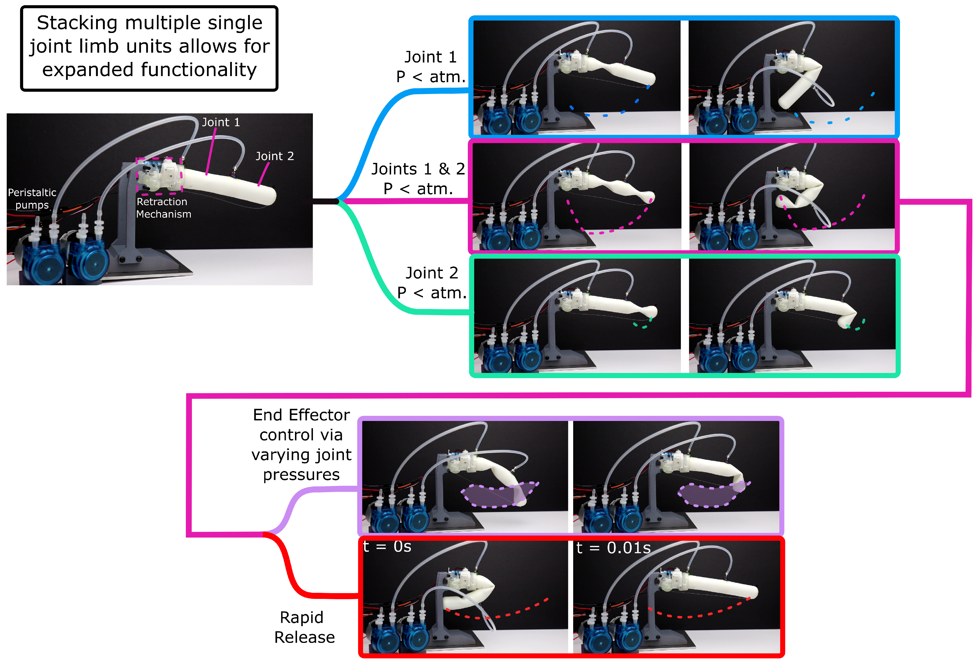
Figure 3.
Demonstration of the multimodal behaviour of a single JUMPER actuator and how stacked joints can exhibit a range of complex angle configurations. A video demonstrating the multi-modal behaviour of the multi-jointed JUMPER system can be found here: https://vimeo.com/1089032212/70b518941e.
Figure 3.
Demonstration of the multimodal behaviour of a single JUMPER actuator and how stacked joints can exhibit a range of complex angle configurations. A video demonstrating the multi-modal behaviour of the multi-jointed JUMPER system can be found here: https://vimeo.com/1089032212/70b518941e.
2. Materials and Methods
As mentioned in Section 1.1, jumping untethered soft robots offer a promising approach for extraterrestrial exploration. To create a jumping soft robot, the diameter, material, and pressure of the single spider joint must be determined. To identify the optimal joint configuration under a given set of system constraints, we employ a combination of experimental sweeps and parameterised optimisation techniques. We seek to maximise the actuator impulse and minimise the system mass. When considering how these factors will impact the design of a full robot, we can consider four main metrics: (1) the force the actuator can produce over its range of motion, which is equivalent to the work the actuator does during extension (we refer to this as the unloading work (ULW)); (2) the rate at which the actuator can rotate or the Extension Rate (ERT); (3) the amount of volume change required to go from evacuated to any given pressure, described as the Total Volume Change (TVC); and (4) the amount of force the retraction motor needs to wind the evacuated cylinder to 85 degrees (we refer to this as the Vacuum Retraction Force (VRF)).
Göttler et al. demonstrated their spider-inspired limb that has a diameter of 20 mm [22] and tested samples by Hugo and Lee ranged from a length to width ratio of 2.5–5 (15 mm to 30 mm diameters), as a result, the diameters of 16 mm, 20 mm, 24 mm, and 28 mm were selected [31]. Each sample has a length of 50 mm, with 4 mm of solid-filled end pieces for mounting and for the tube inlet. The PLA-printed rigid mounts were epoxied to the test sample to ensure a complete bond (although we later discovered that a mechanical interface can provide the same level of strength with no epoxy). The 6 mm tube is inserted into the sample as a press fit, although this provides a useable seal, epoxy was used to ensure no leakage. The samples were tested from vacuum to 1.5 Bar. Many of the samples are more than capable of being pressurised to over 2.5 Bar (250 kPa, 36 psi), but the risk of rupture increased significantly. The system works with both air and water, but for the experiments we use water such that the compressibility of air does not impact the results.
As shown by Figure 4, we constructed two experimental setups to determine the 4 main parameters. The setup to determine the retraction and extension force utilises a winch driven by a Dynamixel AX-12A (Adafruit part: 4768). The winch pulls on a bearing roller cart, which holds a load cell (RS part: 283-6585). The load cell then applies force to the tip of the cylinder sample being tested. We conducted these tests for a range of pressures from vacuum to 1.5 bar at 0.25 bar increments. In the firmware of the microcontroller, we apply a low pass filter to the load cell output. We determine the angle of the cylinder by the BMI-088 inertial measurement unit (RS part: 245-7082). The orientation of the sample is found by resolving the gravity vector and fusing it with the integrated gyro angle via a complementary filter. The springs visible in the test setup are to help overcome and mitigate friction in the roller during the extension/unwinding phase.
2.1. Determining the Peak Retraction Force and Unloading Work
To determine the peak retraction force, we increase the system volume via the syringe pump until the system reaches -0.5 Bar. We then begin an automated test procedure. The automated procedure begins winding the string at a rate of 50 RPM. This winding pulls the roller cart up the track and the system measures the load via the load cell.
We find the loading and unloading force vs. angle by winding the sample up to 85 degrees and then unwinding at a constant rate. The unloading work over the full sweep of 85 degrees is useful to determine the energy that can be converted into jumping. Due to the aforementioned complexities in the pre- and post-buckling phases, For use in a jumping robot, having a large range of motion and understanding the force behaviour over this range of motion is important. For use cases where a smaller range of motion is desired, the actuator configuration could be selected such that a peak force is provided at or around a specific range of motion.
2.2. Determining the Angular Rate
The experimental setup we used to determine the extension rate utilises 4 infrared object detecting sensors (LM393 based sensor) spaced equally at 22.5-degree increments. These sensors are connected to a Teensy 4.0 (RS part: 283-6910), which is selected for clock cycle speed. We determined, by using a high-speed camera, that the rate of extension would get close to the maximum measurable rate of the BMI-088 IMU, and that the highspeed camera would not have the refresh rate to fully capture the total time accurately. The sample would be pressurised to the desired test pressure, the AX-12A winch would then retract the sample to 85 degrees, and the sample would then be released via the quick-release clip. The IMU would record the angular rate and acceleration of the sample, and the IR sensors would time from when the first sensor would no longer detect the sample. The resulting speed between the two intervals was averaged to provide the rate.
3. Results
The vacuum retraction force would be expected to be primarily a function of material stiffness. The crumpled "peanut" shape shown by Figure 5 means the cross-section for loading has been reduced. There is extensive work on the failure modes of hollow cylinders subject to external pressure, such as the work of Timoshenko and Gere, which describes collapse failure modes [32]. However, there is significantly less work on the collapse of hyperelastic materials, due to the complexity of various collapse modes Finite Element Analysis (FEA) has been employed in recent works. Zhu et al. were able to simulate the observed behaviour that we refer to as "trifolding" where, as demonstrated by Figure 5, the cross-section at larger diameters causes unexpected collapse behaviour. The data indicates that the "trifolding" causes an increase in loading force.
This complexity is why an experimentally driven selection approach was utilised for the VRF. The "trifolding" behaviour introduces unwanted uncertainty around the point of rotation of the actuator. In some instances, the "trifolding" would snap into a "peanut" cross-section; this was the case with the 28 mm 60 A sample. The extension behaviour did not seem to be dramatically impacted by the "trifolding", but the trifolding is important to consider for cases where a specific rotation axis is desirable, such as ours. We observed an interesting phenomenon: the samples that trifold often exhibit a rotation around the longitudinal axis of the cylinder, decreasing their total length as a result.
The speed and unloading experiments conducted allow the investigation of the output power of the various samples. The unloading curve over the 85-degree sweep and the total time to extend can be combined to provide a single power value for each actuator configuration.
From Figure 6, we observe that the power increases with the diameter and pressure of the samples. We attribute this to larger diameters and stiffer materials producing more force over the range of angles. We find that the pressurisation of the cylinder acts as an introduction of energy to the system, and as demonstrated in theory highlighted by Micklem et. al. [34], increases the resistance to buckling. We note that the data presented in Figure 6 aligns with first principle that increasing the pressure and second moment of area alongside increasing material stiffness increases the output power. However, we observe from the contour plots that the relationship is not entirely linear and we identify this as highlighting the complex interplay of material damping and pressure behaviours.
3.1. Optimisation to select an ideal configuration based on system heuristics
Section 3 indicates that the behaviour of the single joint system deviates from theory, making it difficult to purely analytically optimise the configuration. As discussed in Section 1.2, our approach aims to avoid the shortcomings of analytical or simulation by rapid iterations of a single soft joint. The experimental setup is designed such that the key parameters relevant to the task of jumping can be isolated and parameterised. We can then reduce each actuator into four key parameters and assign constraints to the optimisation such that the system informs the choice.
For the single joint of JUMPER, we can reduce each combination of material, diameter, and pressure to four parameters: vacuum retraction force (VRF), total volume change (TVC), unloading work (ULW), and extension rate (ERT). These are the key parameters to optimise. For each configuration, we normalise the experimental results per parameter (VRF, TVC, ULW, ERT) from -10 to 10. A "weight" is assigned to each parameter, representing its importance in the overall system. The weight is a value between 0 and 10, where 0 means the parameter is not important and 10 means the parameter is very important.
Such an abstraction allows for a refinement of the desired configuration and allows a heuristic approach to resolve a multi-parameter problem. The pseudo-code for the optimisation procedure is shown by 1 (the optimisation code is also available https://github.com/Soft-Systems-Group/Spider-Inspired-Soft-Jumping-Actuator):
| Algorithm 1 Calculate Maximum Score from Multiple Normalised Configurations |
|
Based on this optimisation, the parameters for the force of the retraction motor (Figure 1), and the total driveable volume of the selected peristaltic pump we applied to the set of configurations in the optimiser. From Figure 7a, the optimal choice is the 20 mm 70 A durometer cylinder. Figure 7b shows some alternative examples of what the output may look like for various systems to demonstrate how various weights can impact the results. The key benefit of the presented visualisation is that the strengths and weaknesses of the configuration are clearly displayed compared to other close-scoring configurations. The ability to enter different system constraints and to receive a summary of the best possible configurations demonstrates the potential for soft roboticists to make more informed system decisions.
Informed by the system constraints and the results of the optimisation, we inserted the selected cylinder into a simple two-legged untethered spider robot. We designed the robot to serve as a proof of concept for the optimisation and to demonstrate that we can successfully implement the retraction mechanism in a lightweight untethered robot for space exploration applications. We measured the fully assembled robot with its two 300 mAh 1S lipo batteries to have a mass of 197.36 grams.
As shown by Figure 8b, the simple two-legged robot is capable of jumping. Over 8 jumping trials, the robot was able to jump an average 0.92 body lengths comparing its extended length (floor to centre of mass) to its average jumping height and 1.17 body lengths comparing the "stowed" length to its jump height. The multi-modal controlled retraction and extension (shown by Figure 3) alongside the untethered jumping behaviour above makes JUMPER a first of its kind soft robot. The jumping cycle consists of four distinct steps. The pump runs for 20 seconds drawing 1.8 watts of power to evacuate the two cylinders. The motors then retract the limbs for 10 seconds, each drawing 0.175 watts. The peristaltic pump motor then pressurises the limbs for 1 minute to reach 1 bar, consuming the same power as to evacuate the limbs. The two servo motors disengage the clutch system (drawing 0.5 watts each during this operation). As shown by Figure 6, the 70A 20 mm cylinder at 1 bar produces 7.39 watts of mechanical power. For the two limbs this would be a total of 14.78 watts of total mechanical output power. From these values and the measured extension speed of 0.044 seconds for the 70A sample, the energy efficiency is calculated as 0.39%, a nearly 4× improvement to the average efficiency of many soft robots according to Shui et al. [10]. The improvement of efficiency highlights the benefit of a "V-model" of system design, drawing from nature and incorporating multiple modes of operation to optimise performance [13]. This approach allows for more efficient use of energy and resources, leading to improved overall system performance.
4. Discussion
The JUMPER actuator represents a significant advancement in soft robotics by successfully combining bio-inspired design principles with practical engineering solutions for extraterrestrial exploration. The spider-inspired hydraulic extension mechanism provides a compelling framework for achieving the dual objectives of precise control and dynamic actuation within a single system. Our experimental results demonstrate that by manipulating internal pressure, we can effectively switch between controlled positioning and rapid jumping modes, addressing one of the fundamental challenges in soft robotics: the trade-off between controllability and dynamic performance.
The optimisation methodology presented offers a systematic approach to soft actuator design that moves beyond trial-and-error methods. By parameterising key performance metrics and implementing a weighted scoring system, designers can make informed decisions based on specific application requirements. This approach is particularly valuable for space applications where weight, power consumption, and reliability constraints are paramount.
The observed "trifolding" behaviour, while initially presenting challenges for consistent rotation axis control, reveals interesting opportunities for future exploration. This phenomenon could potentially be harnessed for novel actuation modes or multi-axis movement capabilities, expanding the versatility of the actuator design.
The energy efficiency improvement of nearly 4× over typical soft robots (0.39% vs 0.1%) demonstrates the potential of hybrid actuation systems. While still lower than rigid robotic systems, this represents a significant step towards bridging the efficiency gap between soft and traditional robotics. The ability to hold positions with zero energy consumption through the non-backdriveable worm gear mechanism provides additional advantages for space applications where power conservation is critical.
Future work should explore scaling effects, multi-actuator coordination, and integration with advanced sensing systems for autonomous operation in extraterrestrial environments. The modular design of JUMPER enables straightforward integration into larger robotic systems, making it a promising candidate for future space exploration missions.
5. Conclusions
This paper has introduced JUMPER (Joint Unbuckling Mechanism with Pressure-enhanced Extension and Retraction), a novel spider-inspired actuator that exhibits unique multi-modal behaviour—the first of its kind to combine controlled extension/retraction with dynamic jumping capability. By drawing inspiration from spider physiology, we’ve demonstrated how bio-inspiration can be effectively translated into practical soft robotic systems that address the core challenges of untethered soft robotics: power density, control complexity, and energy efficiency. We show how the single joint unit can be extended for complex locomotion behaviour, or used more simply in a small untethered robot.
Our approach utilises rapid prototyping through 3D printing to explore systematically and optimise the design space across multiple parameters—material stiffness, cylinder diameter, and operating pressure—enabling a practical, experiment-driven optimisation methodology. This approach circumvents the limitations of analytical or simulation-based methods when dealing with the complex non-linear behaviours of soft materials under varying pressure conditions. The resulting actuator demonstrates significant performance improvements when compared to existing soft jumping mechanisms, exhibiting controlled motion during normal operation while maintaining the ability to rapidly deploy stored energy for jumping.
Drawing inspiration from spider hydraulic mechanisms, JUMPER achieves a significant advancement in soft robotic actuation efficiency by switching between different operational modes. Our experimental results demonstrate that pressure modulation enables direct control over both actuator stiffness and dynamic response characteristics, seamlessly transitioning between precise positioning and high-energy jumping behaviours within a single device. This dual-mode functionality positions JUMPER as an ideal candidate for extraterrestrial exploration missions, where the combination of adaptability, reliability, and energy efficiency is essential for mission success.
Furthermore, the parametric optimisation methodology we presented provides a framework for designing application-specific soft actuators that can be tailored to meet the constraints of various deployment scenarios. The visualisation of multiple performance metrics —simultaneously —enables designers to make informed trade-offs between competing objectives, a critical capability for the development of practical untethered soft robots.
JUMPER demonstrates that combining bio-inspiration with systematic experimental optimisation can yield soft robotics solutions that overcome many of the traditional limitations of the field. The lightweight, energy-efficient design, coupled with its multi-modal operation capabilities, positions this actuator as a promising technology for future extraterrestrial exploration missions where adaptability and robustness are essential.
Author Contributions
Conceptualisation, J.M; methodology, J.M and M.G; software, J.M; validation, J.M.; formal analysis, J.M, F.GS, and AS; investigation, J.M; writing—original draft preparation, J.M and M.G.; writing—review and editing, F.GS and AS; All authors have read and agreed to the published version of the manuscript.
Funding
This research was funded by EPSRC Centre for Doctoral Training in Robotics and Autonomous Systems (CDT-RAS), grant number EP/S023208/1.
Institutional Review Board Statement
Not applicable. This study did not involve humans or animals.
Informed Consent Statement
Not applicable. This study did not involve humans.
Data Availability Statement
The data, optimisation algorithms, JUMPER CAD files, and figure generation code are openly available at https://github.com/Soft-Systems-Group/Spider-Inspired-Soft-Jumping-Actuator.
Conflicts of Interest
The authors declare no conflicts of interest. The funders had no role in the design of the study; in the collection, analyses, or interpretation of data; in the writing of the manuscript; or in the decision to publish the results.
Abbreviations
The following abbreviations are used in this manuscript:
| JUMPER | Joint Unbuckling Mechanism with Pressure-enhanced Extension and Retraction |
| TPU | Thermoplastic Polyurethane |
| FDM | Fused Deposition Modelling |
| VRF | Vacuum Retraction Force |
| TVC | Total Volume Change |
| ULW | Unloading Work |
| ERT | Extension Rate |
| FEA | Finite Element Analysis |
| IMU | Inertial Measurement Unit |
References
- Terramechanics-based model for steering maneuver of planetary exploration rovers on loose soil - Ishigami - 2007 - Journal of Field Robotics - Wiley Online Library. [CrossRef]
- Chen, G.; Qiao, L.; Zhou, Z.; Richter, L.; Ji, A. Development of a Lizard-Inspired Robot for Mars Surface Exploration. Biomimetics 2023, 8, 44. [Google Scholar] [CrossRef] [PubMed]
- Feng, R.; Zhang, Y.; Liu, J.; Zhang, Y.; Li, J.; Baoyin, H. Soft Robotic Perspective and Concept for Planetary Small Body Exploration. Soft Robotics 2022, 9, 889–899. [Google Scholar] [CrossRef] [PubMed]
- Ng, C.S.X.; Lum, G.Z. Untethered Soft Robots for Future Planetary Explorations? Advanced Intelligent Systems 2023, 5, 2100106, _eprint: https://onlinelibrary.wiley.com/doi/pdf/10.1002/aisy.202100106. [Google Scholar] [CrossRef]
- Berlinger, F.; Duduta, M.; Gloria, H.; Clarke, D.; Nagpal, R.; Wood, R. A modular dielectric elastomer actuator to drive miniature autonomous underwater vehicles. In Proceedings of the 2018 IEEE International Conference on Robotics and Automation (ICRA). IEEE; 2018; pp. 3429–3435. [Google Scholar]
- Sayed, M.E.; Roberts, J.O.; McKenzie, R.M.; Aracri, S.; Buchoux, A.; Stokes, A.A. Limpet II: A modular, untethered soft robot. Soft robotics 2021, 8, 319–339. [Google Scholar] [CrossRef] [PubMed]
- Li, T.; Li, G.; Liang, Y.; Cheng, T.; Dai, J.; Yang, X.; Liu, B.; Zeng, Z.; Huang, Z.; Luo, Y.; et al. Fast-moving soft electronic fish. Science advances 2017, 3, e1602045. [Google Scholar] [CrossRef] [PubMed]
- Tang, Y.; Chi, Y.; Sun, J.; Huang, T.H.; Maghsoudi, O.H.; Spence, A.; Zhao, J.; Su, H.; Yin, J. Leveraging elastic instabilities for amplified performance: Spine-inspired high-speed and high-force soft robots. Science Advances 2020, 6, eaaz6912, Publisher: American Association for the Advancement of Science. [Google Scholar] [CrossRef] [PubMed]
- Batts, Z.; Kim, J.; Yamane, K. Untethered one-legged hopping in 3d using linear elastic actuator in parallel (leap). In Proceedings of the International Symposium on Experimental Robotics. Springer; 2016; pp. 103–112. [Google Scholar]
- Shui, L.; Zhu, L.; Yang, Z.; Liu, Y.; Chen, X. Energy efficiency of mobile soft robots. 13, 8223–8233. [CrossRef]
- Kim, D.; Di Carlo, J.; Katz, B.; Bledt, G.; Kim, S. Highly dynamic quadruped locomotion via whole-body impulse control and model predictive control. arXiv preprint arXiv:1909.06586 2019. [Google Scholar]
- Reher, J.; Ames, A.D. Dynamic Walking: Toward Agile and Efficient Bipedal Robots. Annual Review of Control, Robotics, and Autonomous Systems 2021, 4, 535–572. [Google Scholar] [CrossRef]
- Chun, H.T.D.; Taylor, N.K.; Stokes, A.A. Energy-Based Abstraction for Soft Robotic System Development. Advanced Intelligent Systems 2023, 5, 2000264. [Google Scholar] [CrossRef]
- Rich, S.I.; Wood, R.J.; Majidi, C. Untethered soft robotics. 1, 102–112. Publisher: Nature Publishing Group. [CrossRef]
- Tolley, M.T.; Shepherd, R.F.; Karpelson, M.; Bartlett, N.W.; Galloway, K.C.; Wehner, M.; Nunes, R.; Whitesides, G.M.; Wood, R.J. An untethered jumping soft robot. In Proceedings of the 2014 IEEE/RSJ International Conference on Intelligent Robots and Systems, pp. 561–566. ISSN: 2153-0866. [CrossRef]
- Li, S.; Rus, D. JelloCube: A Continuously Jumping Robot With Soft Body. 24, 447–458. Conference Name: IEEE/ASME Transactions on Mechatronics. [CrossRef]
- Sayed, M.E.; Roberts, J.O.; McKenzie, R.M.; Aracri, S.; Buchoux, A.; Stokes, A.A. Limpet II: A Modular, Untethered Soft Robot. Soft Robotics 2021, 8, 319–339, Publisher: Mary Ann Liebert, Inc., publishers. [Google Scholar] [CrossRef] [PubMed]
- Shultz, J.W. Evolution of locomotion in arachnida: The hydraulic pressure pump of the giant whipscorpion, Mastigoproctus Giganteus (Uropygi). Journal of Morphology 1991, 210, 13–31. [Google Scholar] [CrossRef] [PubMed]
- Sensenig, A.T.; Shultz, J.W. Mechanics of cuticular elastic energy storage in leg joints lacking extensor muscles in arachnids. 206, 771–784. [CrossRef]
- Manton, S.; Harding, J. Hydrostatic pressure and leg extension in arthropods, with special reference to arachnids. Annals and Magazine of Natural History 1958, 1, 161–182. [Google Scholar] [CrossRef]
- Spröwitz, A.; Göttler, C.; Sinha, A.; Caer, C.; Öoztekin, M.U.; Petersen, K.; Sitti, M. Scalable pneumatic and tendon driven robotic joint inspired by jumping spiders. In Proceedings of the 2017 IEEE International Conference on Robotics and Automation (ICRA). IEEE; 2017; pp. 64–70. [Google Scholar]
- Göttler, C.; Elflein, K.; Siegwart, R.; Sitti, M. Spider Origami: Folding Principle of Jumping Spider Leg Joints for Bioinspired Fluidic Actuators. 8, 2003890. [CrossRef]
- Göttler, C.; Amador, G.; Kamp, T.v.d.; Zuber, M.; Böhler, L.; Siegwart, R.; Sitti, M. Fluid mechanics and rheology of the jumping spider body fluid. 17, 5532–5539. Publisher: Royal Society of Chemistry. [CrossRef]
- Landkammer, S.; Valek, R.; Hornfeck, R. A novel bio-inspired fluidic actuator for robotic applications. In Proceedings of the ICAST2014-International Conference for Adaptive Structures and Technologies, The Hague, 2014.
- Kellaris, N.; Rothemund, P.; Zeng, Y.; Mitchell, S.K.; Smith, G.M.; Jayaram, K.; Keplinger, C. Spider-Inspired Electrohydraulic Actuators for Fast, Soft-Actuated Joints. 8, 2100916. _eprint: https://onlinelibrary.wiley.com/doi/pdf/10.1002/advs.202100916. [CrossRef]
- Nemiroski, A.; Shevchenko, Y.Y.; Stokes, A.A.; Unal, B.; Ainla, A.; Albert, S.; Compton, G.; MacDonald, E.; Schwab, Y.; Zellhofer, C.; et al. Arthrobots. 4, 183–190. Publisher: Mary Ann Liebert, Inc., publishers. [CrossRef]
- Smith, G.L.; Tyler, J.B.; Lazarus, N.; Tsang, H.; Viornery, L.; Shultz, J.; Bergbreiter, S. Spider-Inspired, Fully 3D-Printed Micro-Hydraulics for Tiny, Soft Robotics. n/a, 2207435. _eprint: https://onlinelibrary.wiley.com/doi/pdf/10.1002/adfm.202207435. [CrossRef]
- Menon, C.; Lira, C. Spider-inspired embedded actuator for space applications. AISB’06—Adaptation in Artificial and Biological Systems (Bristol) 2006.
- Propistsova, E.A.; Makarova, A.A.; Eskov, K.Y.; Polilov, A.A. Miniaturization does not change conserved spider anatomy, a case study on spider Rayforstia (Araneae: Anapidae). Scientific Reports 2023, 13, 17219, Publisher: Nature Publishing Group. [Google Scholar] [CrossRef] [PubMed]
- Gepner, M.; Mack, J.; Stokes, A.A. A standardized platform for translational advances in fluidic soft systems. Device 2025. Publisher: Elsevier. [CrossRef]
- Lee, H.; Rodrigue, H. Harnessing the nonlinear properties of buckling inflatable tubes for complex robotic behaviors. 63, 59–88. [CrossRef]
- Timoshenko, S.P.; Gere, J.M. Theory of elastic stability; Courier Corporation, 2009.
- Zhu, Y.; Luo, X.Y.; Wang, H.M.; Ogden, R.W.; Berry, C. Three-dimensional non-linear buckling of thick-walled elastic tubes under pressure. 48, 1–14. [CrossRef]
- Micklem, L.; Weymouth, G.; Thornton, B. Energy-efficient tunable-stiffness soft robots using second moment of area actuation. In Proceedings of the 2022 IEEE/RSJ International Conference on Intelligent Robots and Systems (IROS); 2022; pp. 5464–5469, ISSN 2153-0866. [Google Scholar] [CrossRef]
Figure 1.
(A) cartoon demonstration of the key hydraulic features of a spider (informed by [22,29]), red arrows show oxygenated hemolymph and blue arrows show deoxygenated hemolymph travelling back through empty spaces inside the spider. (B) renders on the right of the figure demonstrate the function of the proposed actuator, highlighting the inspiration drawn between the function of the spider and the actuator. The STEP file to view the retraction mechanism in 3D is available at https://github.com/Soft-Systems-Group/Spider-Inspired-Soft-Jumping-Actuator.
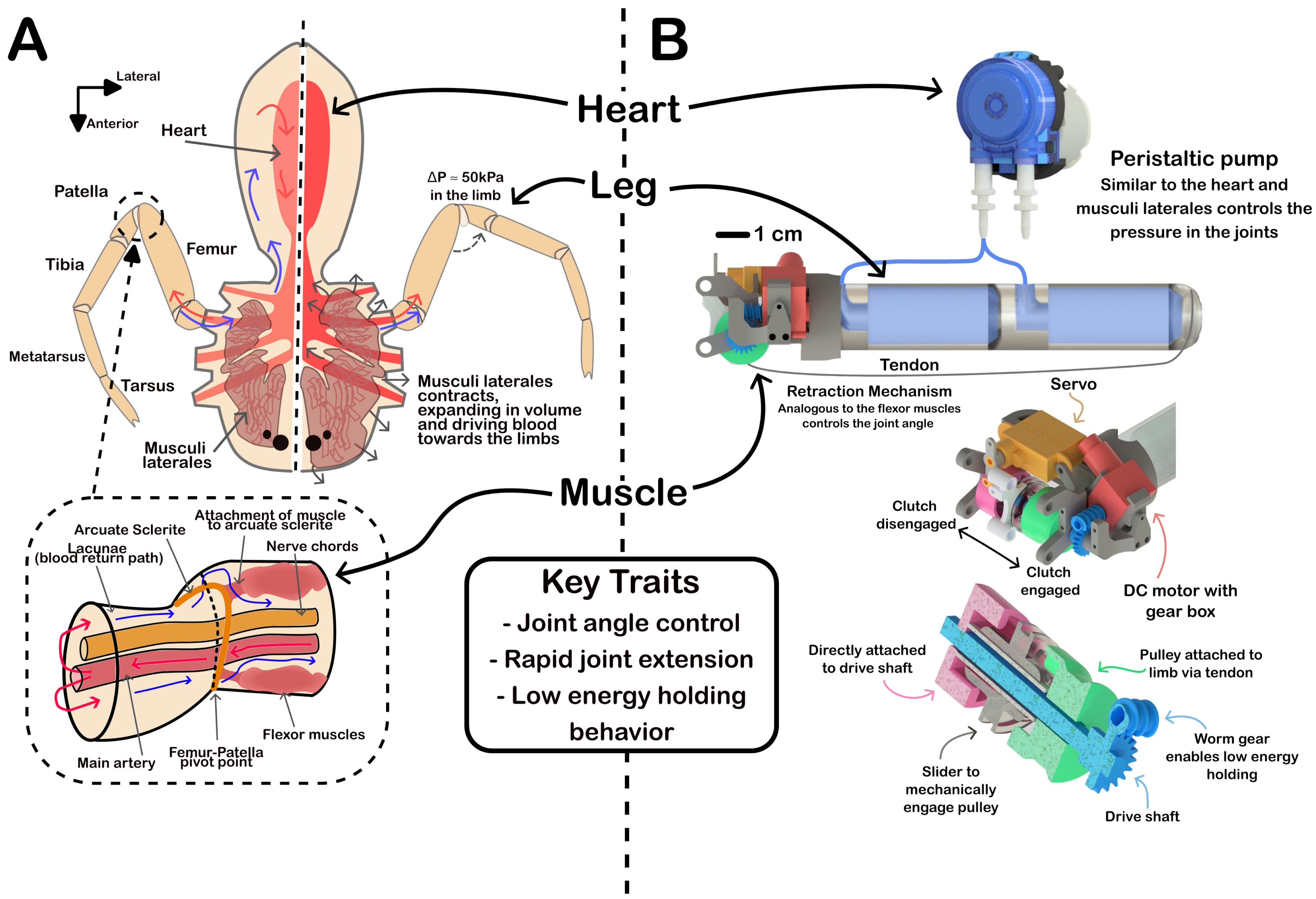
Figure 2.
(A - C) Loading and unloading behaviour of the 20 mm diameter cylinder at different pressures for different materials, showing the significantly reduced loading force for vacuum conditions. (D) The proposed actuation cycle, where the cylinder is at vacuum for retraction then pressurised for extension.
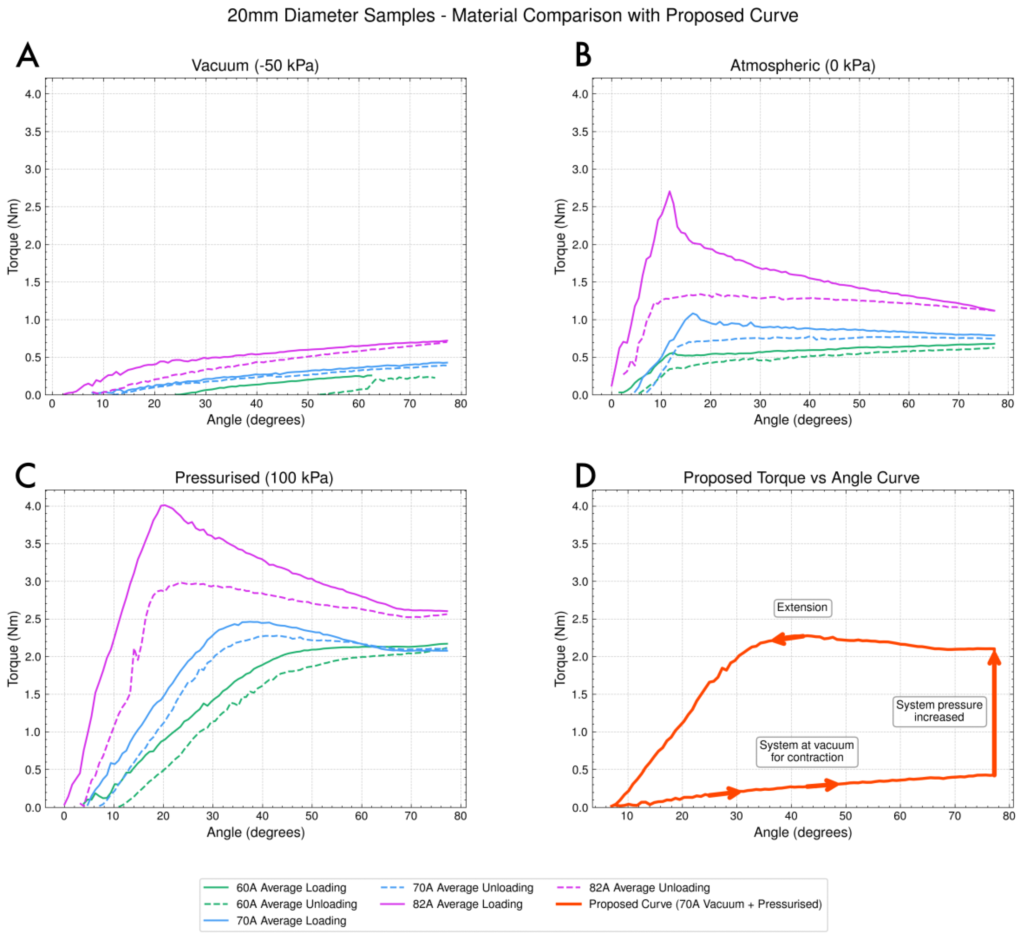
Figure 4.
The experimental setup to determine the speed of the sample via time between trigger signals, and an IMU, with a 600 MHz processor (A) and the setup to determine peak force and work with a 10 kg loadcell on a circular arc track (B).
Figure 4.
The experimental setup to determine the speed of the sample via time between trigger signals, and an IMU, with a 600 MHz processor (A) and the setup to determine peak force and work with a 10 kg loadcell on a circular arc track (B).
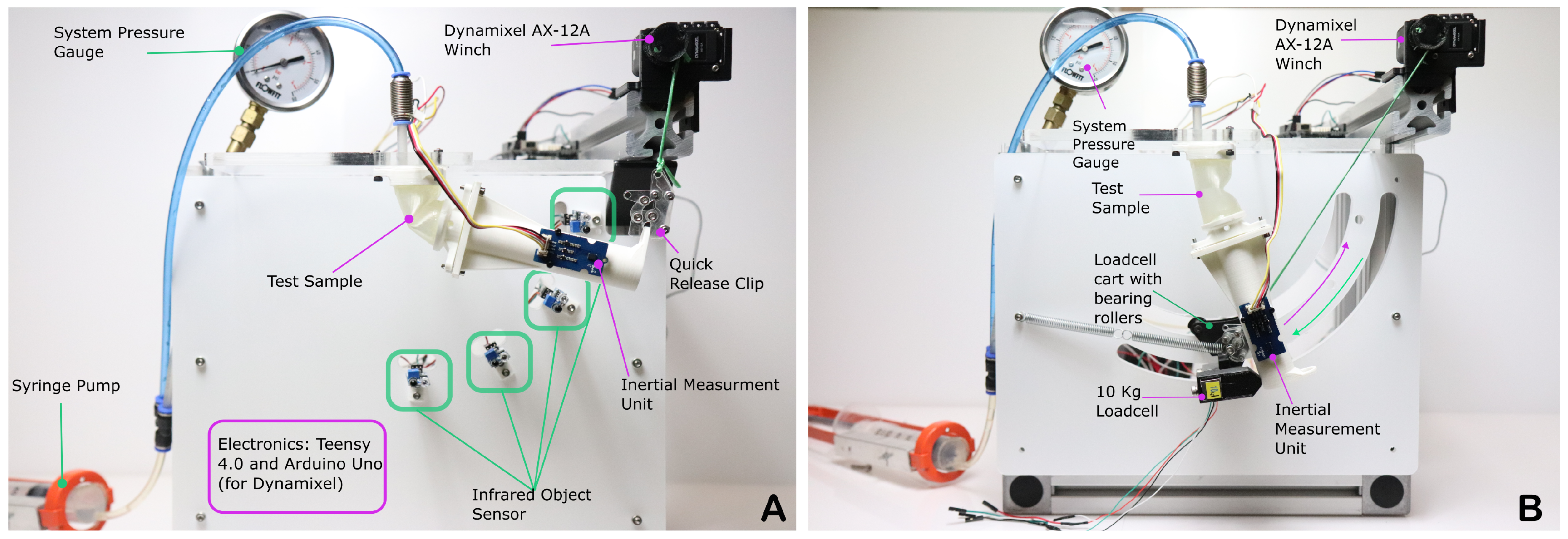
Figure 5.
Peak measured retraction force for the evacuated cylinder with observed difference in cross sections (cross sections recreated from [33]).
Figure 5.
Peak measured retraction force for the evacuated cylinder with observed difference in cross sections (cross sections recreated from [33]).
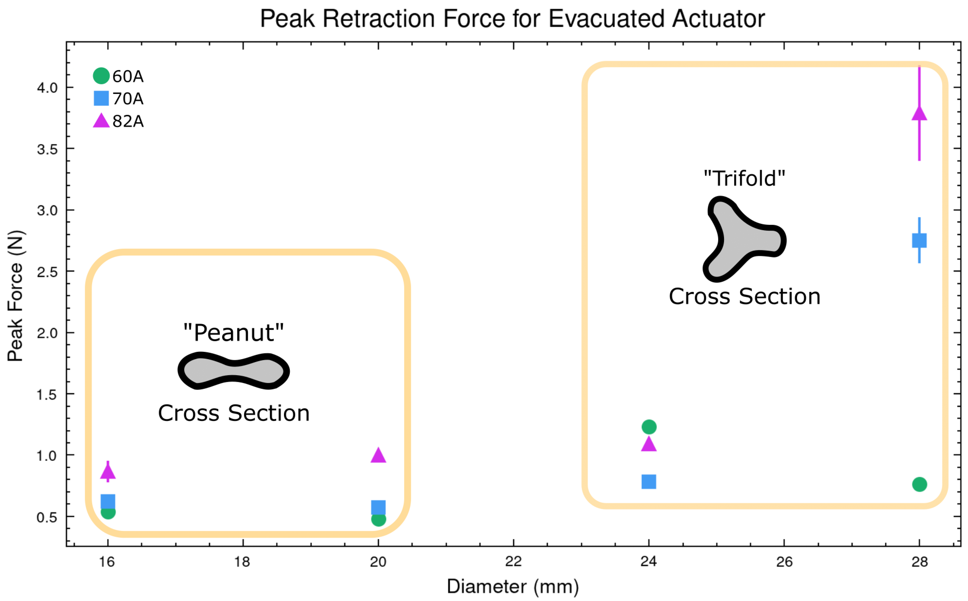
Figure 6.
Contour plot of the power during the extension phase of 85 degrees of tested samples across the three materials. Each sample of varying diameter and material was testrdf at each pressure three times. (Note: the colour scale is different for the 3 contours).
Figure 6.
Contour plot of the power during the extension phase of 85 degrees of tested samples across the three materials. Each sample of varying diameter and material was testrdf at each pressure three times. (Note: the colour scale is different for the 3 contours).
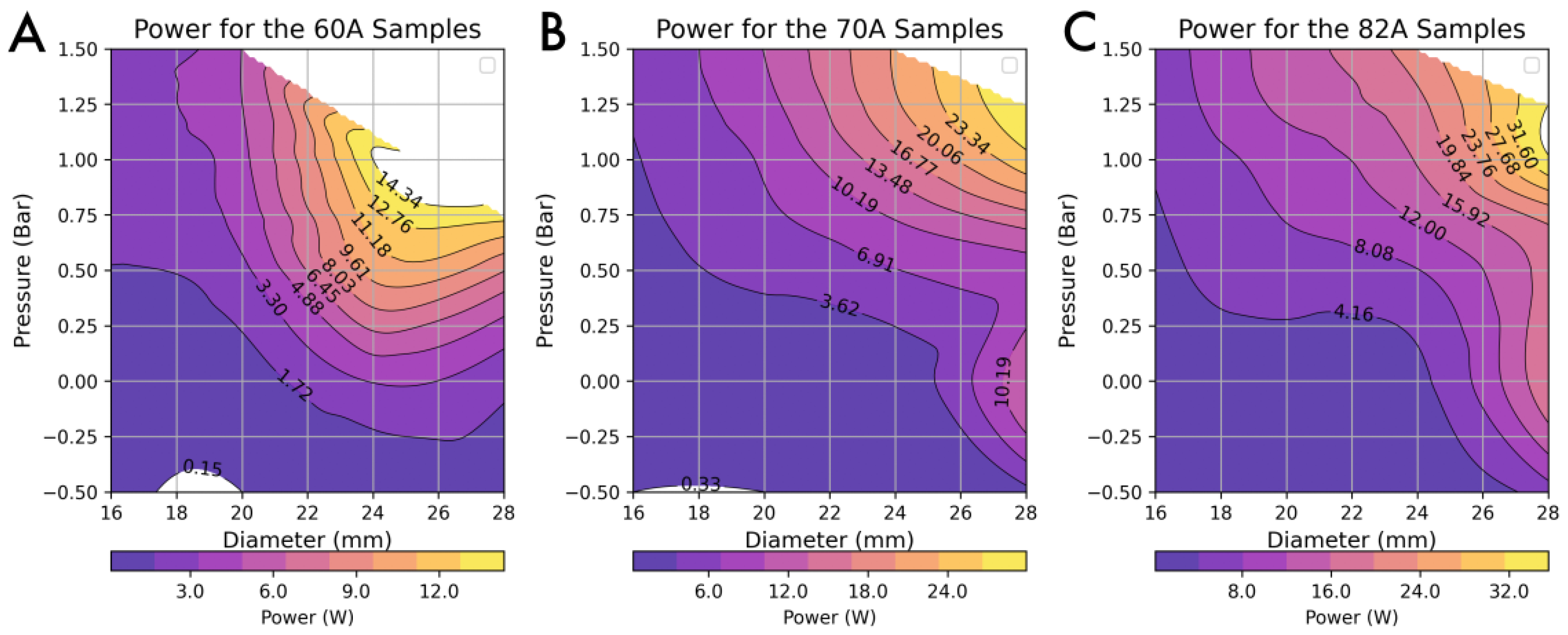
Figure 7.
The visualisation output from the optimisation algorithm that demonstrates the "best in class" configuration for the three materials. (A) shows the output for the proposed system. () show example outputs with various weights applied.
Figure 7.
The visualisation output from the optimisation algorithm that demonstrates the "best in class" configuration for the three materials. (A) shows the output for the proposed system. () show example outputs with various weights applied.
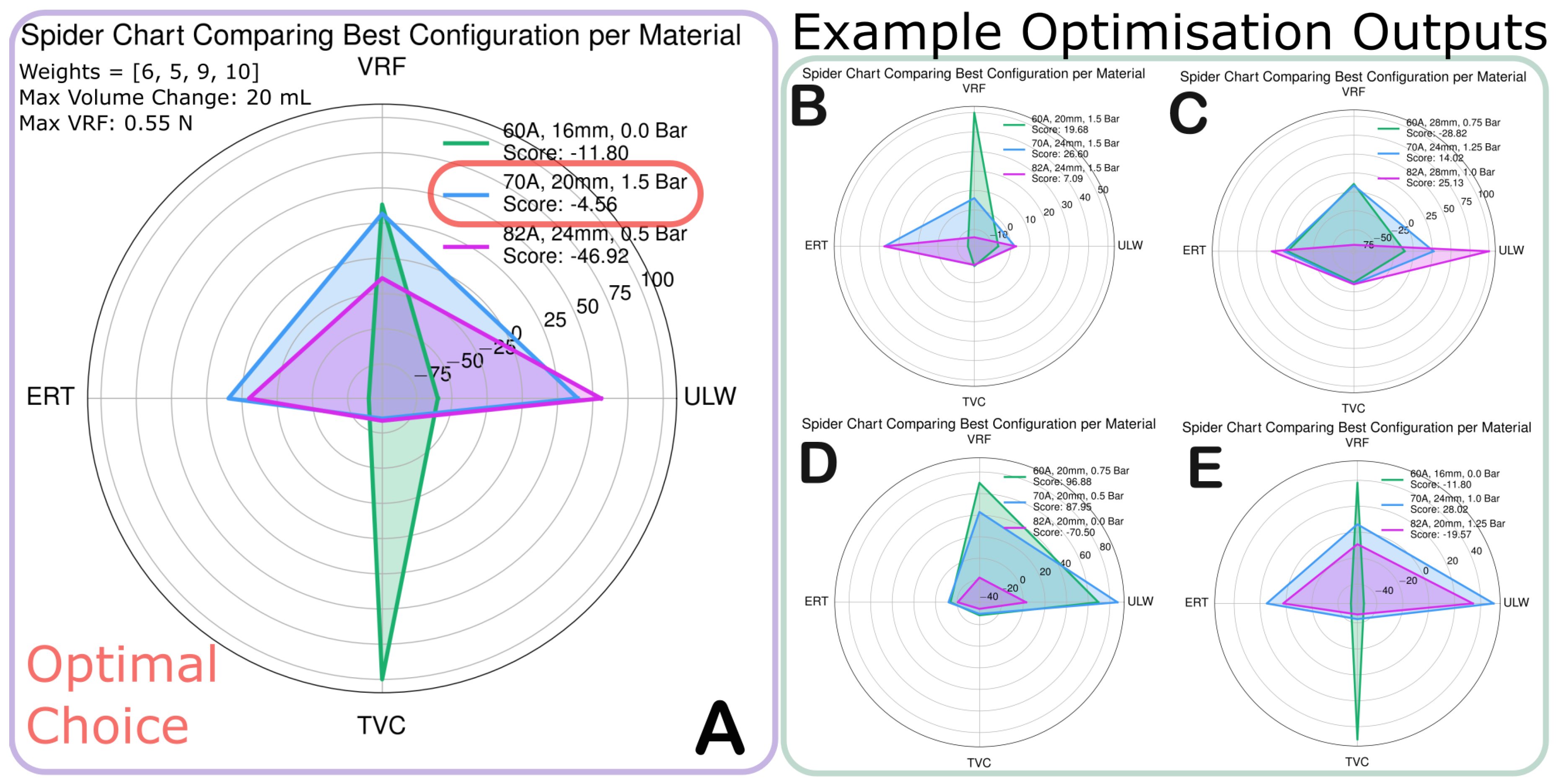
Figure 8.
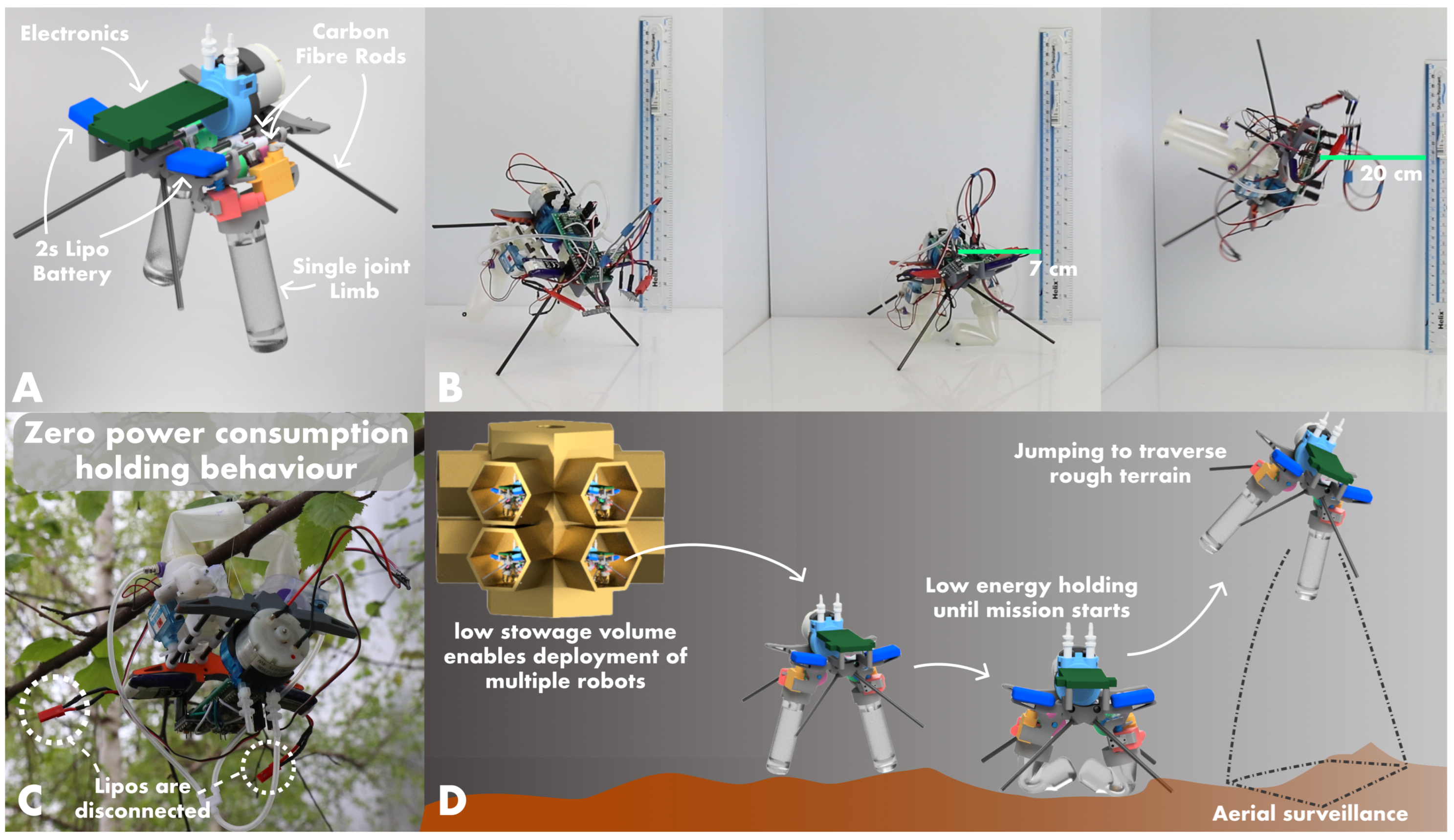
(A) Main components of the full robot utilizing two single unit JUMPER actuators. (B) The robot performs controlled extension and an untethered jump. A video can be found here: https://vimeo.com/1089032212/70b518941e (C) The robot can maintain retracted positions indefinitely and without power, here we show the robot holding onto a tree branch without power, demonstrating the extended lifetime of operation. (D) A cartoon render illustrating a potential implementation of the simple robot for aerial surveillance and exploration over rough terrain on extraterrestrial surfaces.
Figure 8.
(A) Main components of the full robot utilizing two single unit JUMPER actuators. (B) The robot performs controlled extension and an untethered jump. A video can be found here: https://vimeo.com/1089032212/70b518941e (C) The robot can maintain retracted positions indefinitely and without power, here we show the robot holding onto a tree branch without power, demonstrating the extended lifetime of operation. (D) A cartoon render illustrating a potential implementation of the simple robot for aerial surveillance and exploration over rough terrain on extraterrestrial surfaces.
Disclaimer/Publisher’s Note: The statements, opinions and data contained in all publications are solely those of the individual author(s) and contributor(s) and not of MDPI and/or the editor(s). MDPI and/or the editor(s) disclaim responsibility for any injury to people or property resulting from any ideas, methods, instructions or products referred to in the content. |
© 2025 by the authors. Licensee MDPI, Basel, Switzerland. This article is an open access article distributed under the terms and conditions of the Creative Commons Attribution (CC BY) license (http://creativecommons.org/licenses/by/4.0/).
Copyright: This open access article is published under a Creative Commons CC BY 4.0 license, which permit the free download, distribution, and reuse, provided that the author and preprint are cited in any reuse.


