
Submitted:
30 May 2025
Posted:
01 June 2025
You are already at the latest version
Abstract
This research presents a comprehensive thermal performance evaluation of a heat-generating fluid within a magnetohydrodynamic (MHD)-influenced wavy trapezoidal cavity containing a centrally positioned heated solid square block. The study systematically explores the effects of varying Rayleigh number (Ra), Hartmann number (Ha), and internal heat generation coefficient (Δ) on natural convection, flow structure, and thermal transport inside the cavity. Numerical simulations were carried out for a wide range of parameters: Ra (10³–10⁵), Ha (0, 10, 20), and Δ (0, 5, 10). Streamline analysis demonstrates that as Δ increases, the flow circulation becomes more vigorous and buoyancy-driven, resulting in intensified and asymmetric vortex formations around the heated block. However, increasing Ha exerts a damping influence, suppressing fluid motion and limiting the strength of recirculating vortices. Isotherm analysis reveals that heat generation causes tighter and more distorted temperature contours, indicating higher thermal gradients and stronger convective effects. In contrast, a higher Hartmann number smooths out the isotherms, indicating reduced thermal mixing and dominant conduction. The average Nusselt number decreases consistently with increasing Ha and Δ, illustrating that magnetic suppression and internal heat generation reduce the wall heat transfer rate. The highest thermal performance is observed for low Ha and Δ, while the lowest is found at high Ha and Δ combinations. The study concludes that while internal heat generation enhances internal fluid circulation, it lowers overall thermal efficiency under stronger magnetic field conditions. These findings offer insights into optimizing thermal management systems where internal heating and electromagnetic fields are present.
Keywords:
magnetohydrodynamic
; mixed convection
; wavy-walled
; lid-driven trapezoidal cavity
; heat generation
1. Introduction
The study of mixed convection in complex cavity geometries under the influence of magnetohydrodynamic (MHD) forces has gained significant attention due to its applicability in thermal energy storage, electronic cooling, and solar collector systems. In particular, the thermal performance of enclosures subjected to internal heat generation and external magnetic fields, embedded with solid heat sources, has become a focal point for advanced convective heat transfer enhancement techniques.
Hasan et al. [1] investigated MHD convection incorporating Joule heating and internal heat generation in a dual-layered porous chamber, revealing the complex interaction between magnetic field strength and internal energy release. A subsequent study by Hasan and Saha [2] emphasized the role of rotating solid cylinders in MHD conjugate mixed convection environments, showing enhanced heat transfer characteristics. Mirzaei et al. [3] extended the analysis to wavy porous cavities, indicating how surface undulations under magnetic fields affect free convection behaviors. Entropy generation, a measure of thermodynamic irreversibility, has been comprehensively reviewed by Jumadi et al. [4] for rectangular enclosures, identifying the role of boundary layer disruption and thermal gradients. Zemani et al. [5] studied natural convection in a square cavity with a curved hot wall, identifying how wall shaping influences local heat flux distributions. On the geometrical frontier, Mustafa [6] adopted constructed theory to design parabolic enclosures, illustrating the significance of shape optimization in natural convection. Rahaman et al. [7] examined stratified air-filled trapezoidal cavities, emphasizing transient effects on heat transfer. Adebayo et al. [8] focused on natural convection around a concentric elliptical cylinder inside trapezoidal cavities, highlighting the sensitivity of Nusselt number to curvature and enclosure height. Wall geometry plays a critical role in convective flow dynamics. Mohebbi et al. [9] demonstrated that sinusoidal boundaries significantly alter fluid circulation within C-shaped enclosures. Similarly, Yaseen et al. [10] explored mixed convection in triangular cavities containing wavy porous blocks, showcasing diffusive behavior due to wall and shape perturbations.
Alhasan et al. [11] highlighted the impact of oscillating lids and fin configurations on entropy generation in heat sinks. Daiz et al. [12] employed FEM to analyze heat transfer in circular cavities with corrugated cylinders, stressing the computational significance of geometric complexity. Sultan et al. [13] combined artificial intelligence with simulation to optimize latent heat storage in wavy channels, proposing a neural network-based prediction model for thermal performance. Khan et al. [14] analyzed the coupled effects of permeability variation and adiabatic undulating walls, while another study by Khan et al. [15] simulated MHD flow in trapezoidal cavities with internal obstacles using finite element analysis, reinforcing the importance of cavity shape and magnetic field tuning. Ahmed et al. [16] evaluated the thermal performance of conjugate natural convection in trapezoidal enclosures with surface corrugations, establishing a strong link between wall waviness and overall heat transfer rate. Alam et al. [17] investigated MHD flows in square enclosures with sinusoidal vertical boundaries and Joule heating, validating the dual impact of wall geometry and electromagnetic forces. The contribution of Pensiri and Witayangkurn [18] on natural convection in trapezoidal cavities with wavy tops laid early foundations for geometric heat transfer studies. Corvaro and Paroncini [19] provided experimental validation of numerical predictions for heat strips in square cavities, reinforcing the reliability of computational fluid dynamics (CFD).
Hirpho [20] further examined Casson fluid behavior in enclosures with bottom wavy walls, indicating unique viscosity-driven interactions in MHD environments. Rehman et al. [21] analyzed heat flow around diamond-shaped obstructions in convective fluids, identifying flow separation regions that reduce heat transfer rates. Tasnim et al. [22] conducted a thorough entropy analysis for MHD conjugate convection in chambers containing heated solid and liquid media, accounting for Joule heating effects. Recent works by Sarker et al. have pushed the frontier of lid-driven and block-influenced wavy geometries. Their 2023 study simulated mixed convection in enclosures with blocks in different vertical positions, emphasizing the Richardson number’s impact on vortex formation [23]. Another study modeled the thermal performance of enclosures with dual heated blocks at varying elevations, demonstrating stratification and Nusselt number variation due to block interaction [24]. Finally, their latest work incorporated both internal heat generation and wall waviness in a lid-driven trapezoidal cavity, solving the conjugate heat transfer problem using the Galerkin finite element method [25].
Despite extensive efforts, the combined influence of internal heat generation, wall undulation, solid block heating, and MHD forces in trapezoidal geometries remains relatively underexplored. This study addresses that gap by evaluating the thermal performance of a heat-generating fluid in an MHD-influenced wavy trapezoidal cavity containing a heated solid square block. Emphasis is placed on entropy generation, average Nusselt number, and the effects of Hartmann and Rayleigh numbers, providing insights into thermofluidic optimization in complex geometrical and magnetic field environments.
2. Geometrical Configuration
The geometry (Figure 1) of the study encompasses a wavy-walled trapezoidal cavity, specifically designed to investigate conjugate mixed convection heat transfer with internal heat generation under the influence of an external magnetic field. Centrally located within this enclosure is a solid square block that acts as a uniform heat-generating source, significantly contributing to both the conductive and convective heat transfer processes in the system. This embedded solid block introduces additional thermal complexity and is critical to evaluating localized thermal interactions.
The upper wall of the cavity is configured with a sinusoidal wavy contour, intended to enhance the convective heat transfer by increasing surface area and promoting flow disturbances. This waviness induces complex flow circulations and improves thermal mixing within the cavity. The vertical sidewalls are maintained at a constant cold temperature of Tc=300 K, while the top and bottom walls are thermally insulated, enforcing an adiabatic boundary condition ∂T/∂y=0, thereby localizing the thermal interaction within the fluid and the solid region. All walls, including the surfaces of the solid block, are assumed to satisfy no-slip hydrodynamic conditions with u=v=0. At the solid–fluid interface, conjugate boundary conditions are imposed to ensure the continuity of thermal flux.
Figure 1.
Geometry.
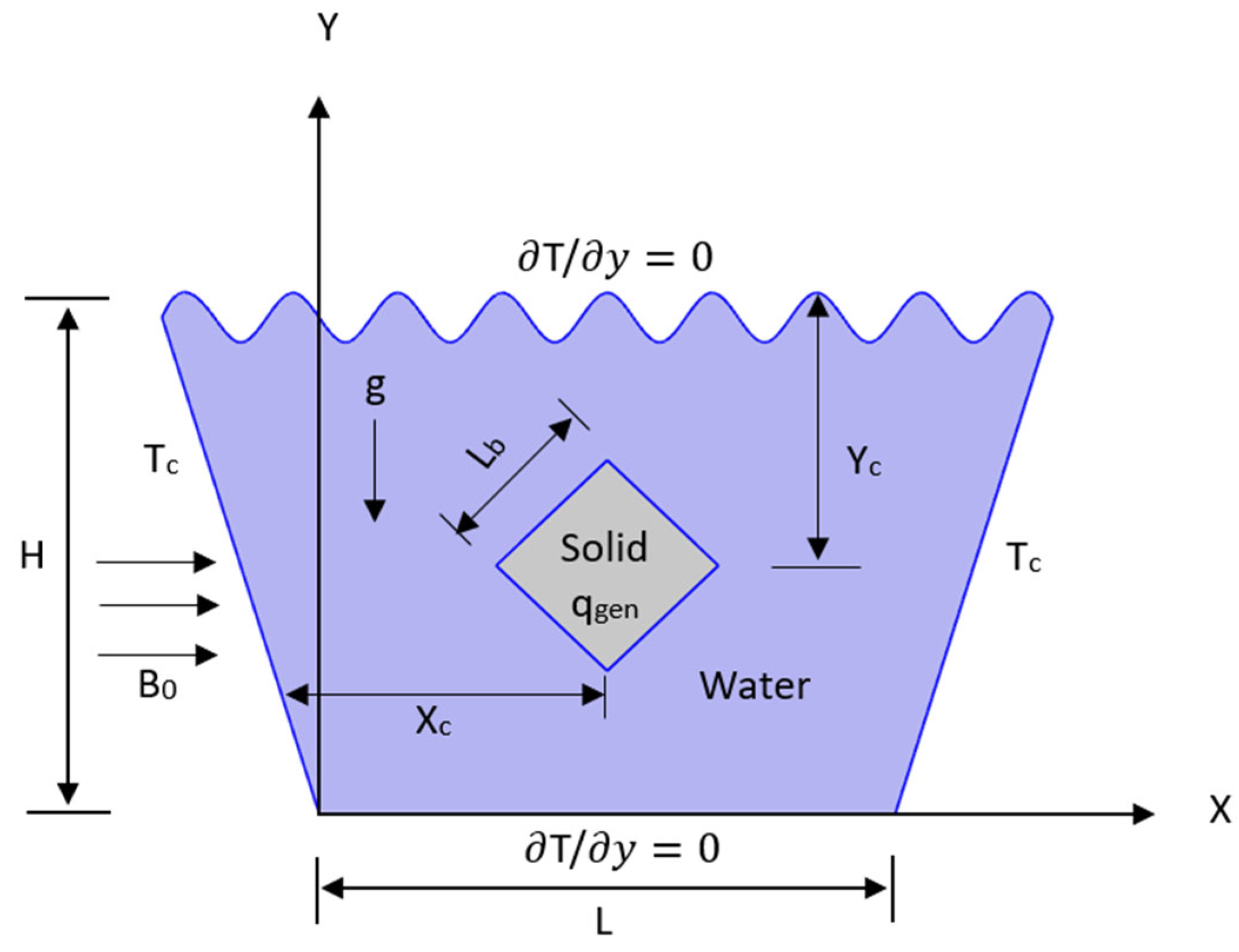
The boundary conditions are as follows in the Table 1:
Furthermore, a uniform horizontal magnetic field B0 is applied, introducing a Lorentz force into the fluid domain, which affects the momentum transport and modifies the flow structure according to the Hartmann number (Ha).
3. Mathematical Model
The mathematical model governing the present study addresses conjugate mixed convection heat transfer in a wavy-walled trapezoidal cavity, influenced by an applied horizontal magnetic field (MHD) and containing a centrally positioned heat-generating solid square block. The model is developed by applying the conservation laws of mass, momentum, and energy within both fluid and solid domains.
The fluid is considered incompressible and Newtonian, with constant thermophysical properties. The flow is two-dimensional, steady, and laminar, and the Boussinesq approximation is invoked to account for buoyancy effects. Heat generation is present within the solid block, and its interaction with the surrounding fluid is modeled via conjugate heat transfer principles.
Governing Equations are (1) to (5) (Dimensional Form):
Fluid Domain:
Solid Domain:
The governing equations (6) to (10) are nondimensionalized using the following dimensionless variables:
Fluid Domain:
Solid Domain:
where, K=ks/kf represents the ratio of the thermal conductivity of the solid domain to that of the working fluid.
Additional dimensionless parameters appearing in equations (6) to (10) include the Rayleigh number, Joule heating parameter, heat generation parameter, Hartmann number, Prandtl number, and the reference temperature difference. These parameters are defined as follows:
The overall thermal performance of the system is quantified using the Average Nusselt number (Nu), which is computed by averaging the local Nusselt numbers on all four sides of the heat-generating solid block. These individual Nusselt numbers (13) to (16) are evaluated using the following mathematical expressions:
Where,
where Ti denotes the temperature prevalent at each side (solid-liquid interface) of the solid element.
The Table 2, shows the Required data of water properties taken at T = 300 K. It includes thermophysical properties of water at a reference temperature of 300 K.
The computational mesh distribution used for the simulation in Figure 2(a–c) demonstrates a progressive refinement from normal to extra finer mesh settings:
Figure 2.
(a-c). Computational Mesh Distribution.
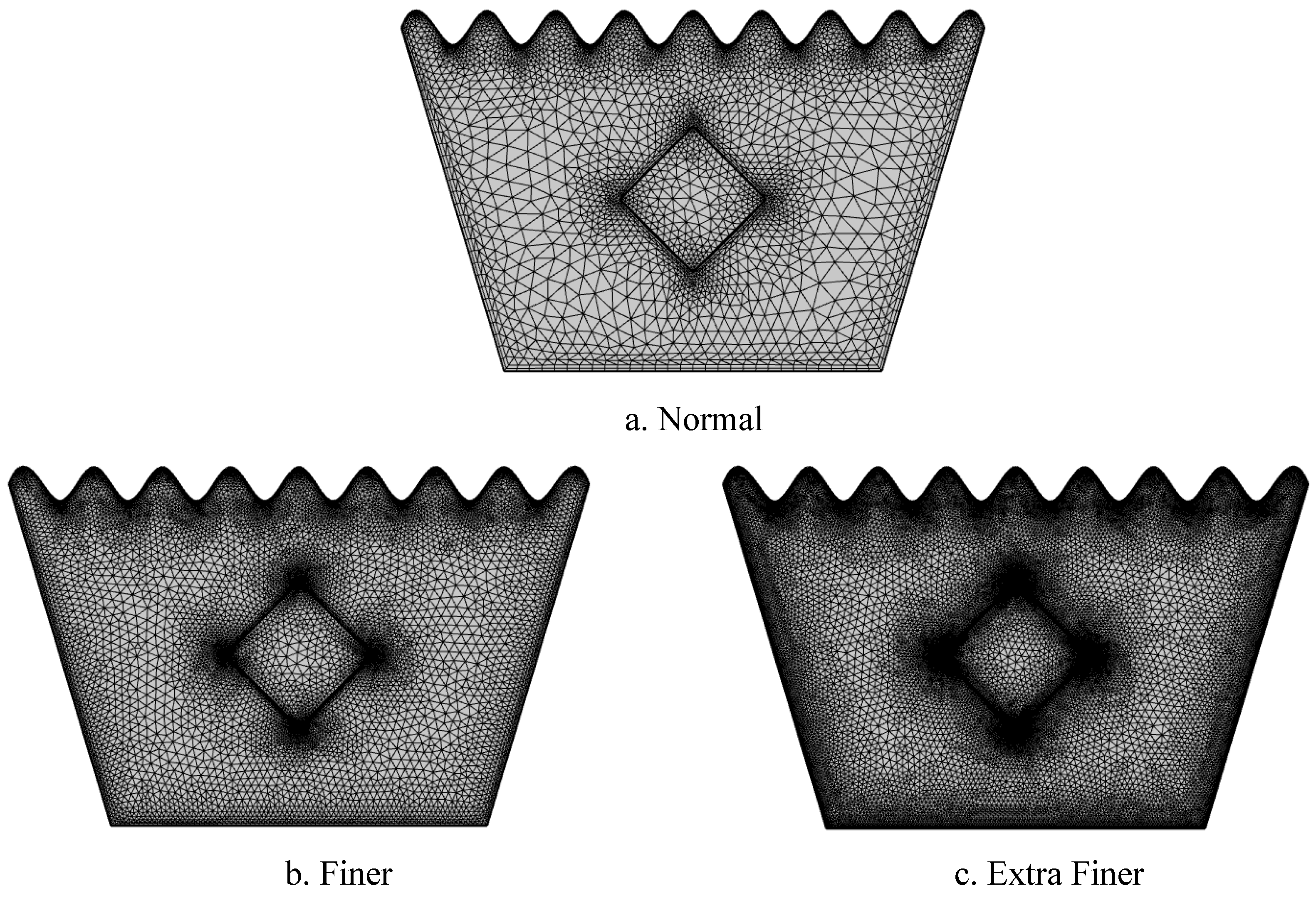
Normal Mesh: The domain includes 7,862 elements, composed of 6,994 triangular and 868 quadrilateral elements with 4,551 vertices. The average element quality is 0.7826, with a minimum quality of 0.2406. The element area ratio is 0.001089, and the mesh area is 1.404 m². This mesh provides a basic resolution suitable for preliminary simulation.
Finer Mesh: The mesh is refined to 19,584 elements, including 18,096 triangles and 1,488 quads, distributed over 10,837 vertices. Here, average element quality improves slightly to 0.7977, while minimum element quality is 0.2353. The element area ratio increases to 0.002584, maintaining the same total mesh area of 1.404 m². This finer mesh enhances accuracy while balancing computational cost.
Extra Finer Mesh: This highly refined mesh contains 41,451 elements with 39,029 triangles and 2,422 quadrilateral elements, defined over 22,411 vertices. The average element quality further improves to 0.8113, though minimum quality decreases to 0.2198, indicating tighter geometric constraints. The element area ratio is reduced to 9.02E-4, maximizing resolution for precise thermal and flow simulations across the cavity domain.
Overall, increasing mesh refinement improves solution accuracy at the expense of higher computational demand, with Figure 2(c) offering the most detailed discretization suitable for advanced numerical analysis.
4. Numerical Procedure
The numerical simulation for the is carried out using the finite element method (FEM), as implemented in COMSOL Multiphysics. This approach provides a reliable and accurate framework to analyze complex geometries and coupled physical phenomena, including mixed convection, magnetic field effects, and internal heat generation.
Figure 3.
Numerical Procedure Flowchart.
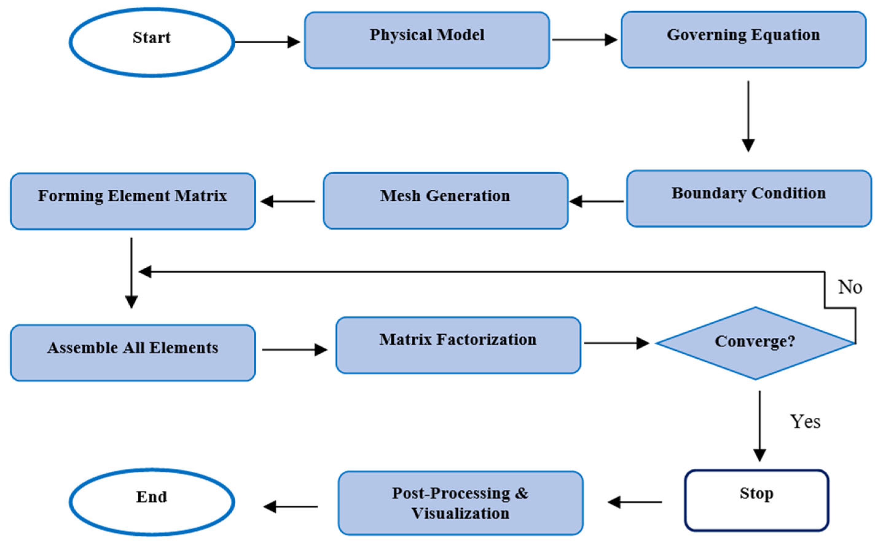
The computational domain comprises a wavy-walled trapezoidal cavity filled with fluid (water), and a centrally located heated solid square block acting as a uniform internal heat source. The fluid-solid interaction is modeled using conjugate heat transfer, which solves the governing equations simultaneously in both domains. To manage the nonlinear coupled governing equations, the Galerkin finite element approach is employed for spatial discretization. Pressure–velocity coupling is handled through a SIMPLE (Semi-Implicit Method for Pressure Linked Equations) algorithm, ensuring numerical stability and convergence.
The procedural steps for the numerical analysis, illustrated in Figure 3, begin with defining the physical model, applying governing equations and boundary conditions, and generating a structured triangular mesh with refinements. The element matrices are formed and assembled into a global system, which is solved using matrix factorization with iterative convergence checks. If convergence criteria are unmet, variables are updated until a steady-state is achieved. Post-processing includes visualizing streamlines, isotherms, and Nusselt number distributions. The simulation results are then evaluated to understand the effects of Rayleigh and Hartmann numbers, heat generation, and geometry, followed by final documentation of insights.
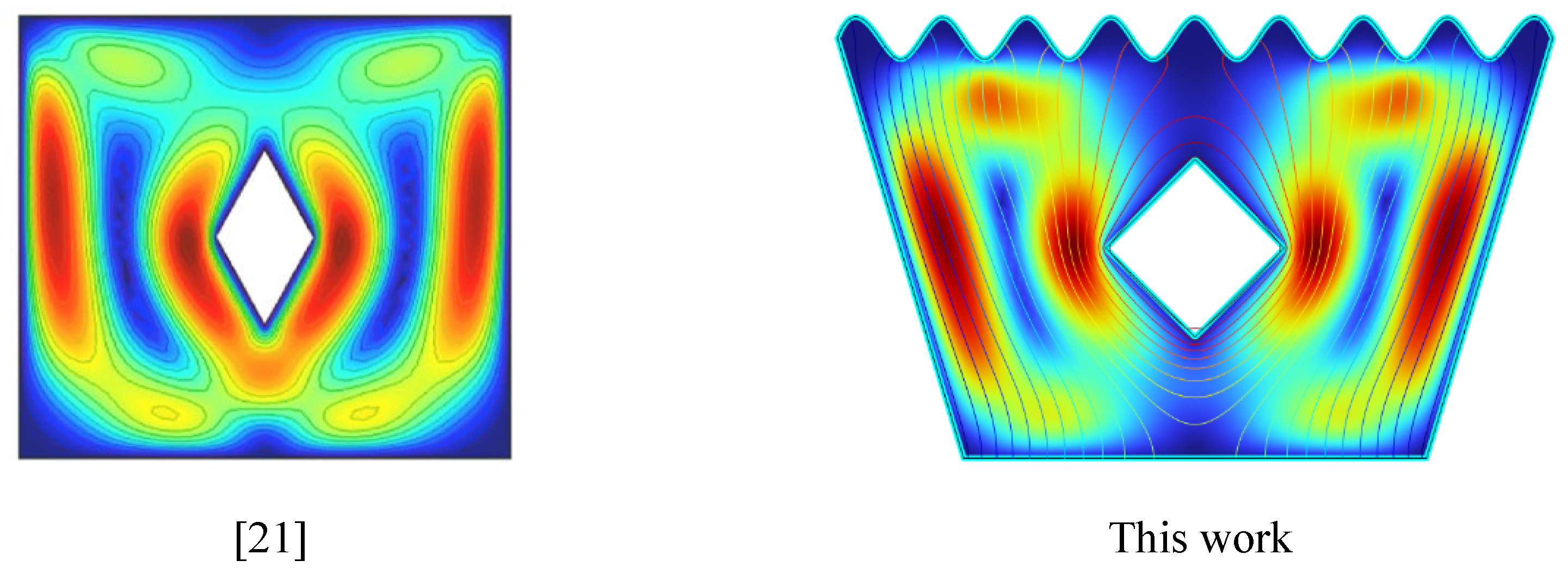
Code Validation: To validate the code used in this investigation, the Velocity Profiles(Fig.4) in this work are compared [21]. The comparisons show a good degree of agreement.
Figure 4.
Code Validation.
5. Results and Discussions
5.1. Streamline Analysis
5.1.1. Streamline Plots for Ra = 10³, Ha = 0, Δ=0, 5, 10
Figure 5.
1(a-c). Streamline Plots (Ra = 103, Ha = 0, Δ=0, 5, 10).

The streamline patterns in Figure 5.1(a–c) reveal a clear progression with increasing heat generation coefficient (Δ). In Figure 5.1(a) for Δ = 0, weak and symmetric vortices form on either side of the heated solid block, indicating minimal flow activity due to the absence of internal heat generation. In Figure 5.1(b) for Δ = 5, the vortices become stronger and slightly asymmetric, suggesting enhanced buoyancy-driven flow as moderate heat is generated. In Figure 5.1(c) for Δ = 10, the flow structure transforms significantly, exhibiting highly intensified vortices and strong upward circulation around the block, characteristic of dominant natural convection. Overall, as Δ increases, the strength of convection and flow circulation around the heated block intensifies markedly.
5.1.2. Streamline Plots for Ra = 10³, Ha = 10, Δ=0, 5, 10
Figure 5.
2(a-c). Streamline Plots (Ra = 103, Ha = 10, Δ=0, 5, 10).
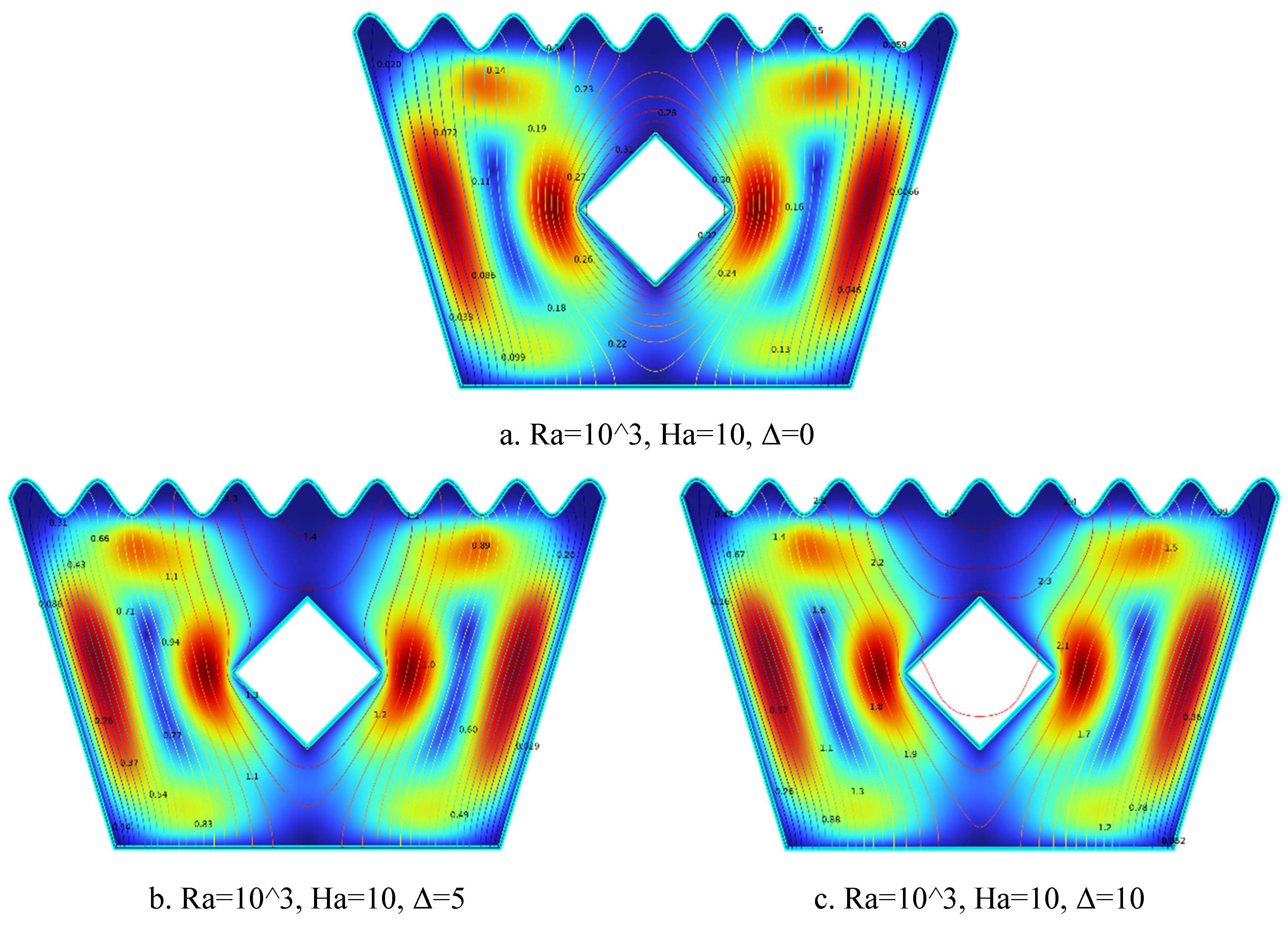
The streamline patterns illustrated in Figure 5.2(a–c) demonstrate the evolving flow behavior at constant Ha = 10 with varying heat generation coefficient (Δ). In Figure 5.2(a) for Δ = 0, weak and symmetric vortices are observed, with overall suppressed flow motion due to the magnetic damping effect and absence of internal heat generation. As shown in Figure 5.2(b) for Δ = 5, the vortices become more pronounced and slightly distorted, indicating that moderate heat generation begins to offset the magnetic suppression and enhance flow strength near the heated block. In Figure 5.2(c) for Δ = 10, strong and asymmetric vortices along with vigorous upward flow emerge, where intense internal heating dominates the flow behavior despite the continued influence of the magnetic field. Overall, increasing Δ enhances buoyancy-driven convection and strengthens circulation, gradually overcoming the magnetic damping effect.
5.1.3. Streamline Plots for Ra = 10³, Ha = 20, Δ=0, 5, 10
Figure 5.
3(a-c). Streamline Plots (Ra = 103, Ha = 20, Δ=0, 5, 10).
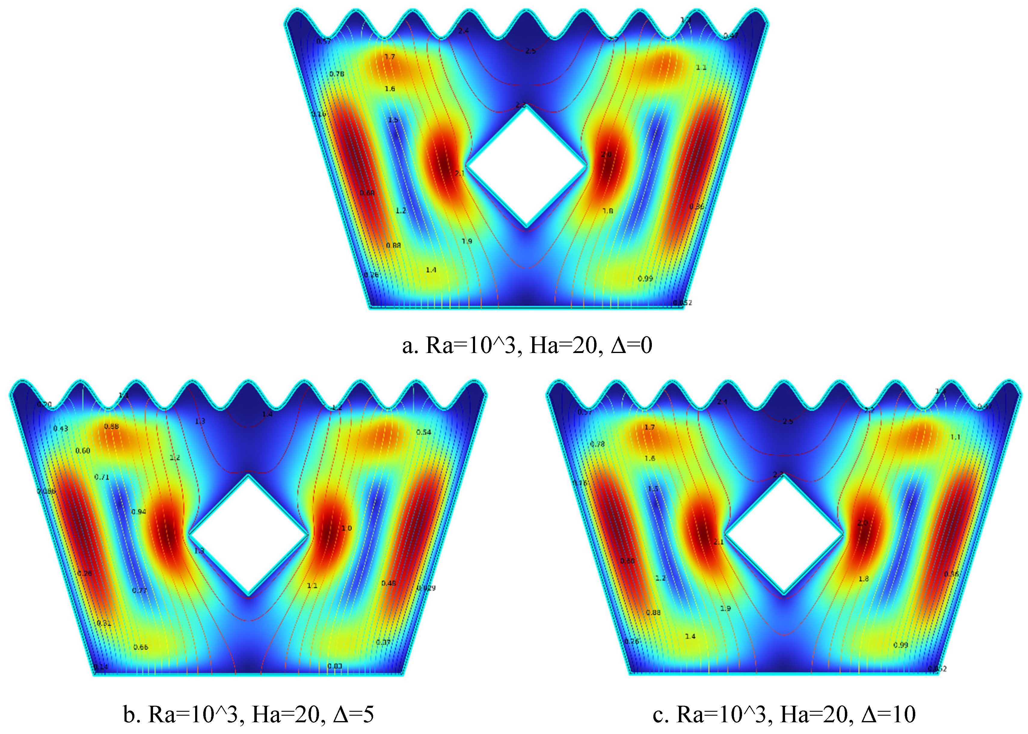
The streamline plots in Figure 5.3(a–c) illustrate the influence of increasing internal heat generation (Δ) on flow behavior at a fixed high Hartmann number. In Figure 5.3(a) for Δ = 0, weak and symmetric recirculation zones appear near the sides of the heated solid block, where the strong magnetic field significantly suppresses fluid motion and the absence of internal heating results in minimal thermal activity. Figure 5.3(b) for Δ = 5 displays more prominent and slightly asymmetric vortices, as moderate internal heat generation enhances buoyancy effects and begins to counteract the magnetic damping. In Figure 5.3(c) for Δ = 10, strong and intensified vortex structures form around the block, with well-developed upward flow patterns. Here, the combined influence of high internal heat generation and magnetohydrodynamic effects leads to vigorous convection. Overall, as Δ increases, buoyancy-driven convection becomes more dominant, resulting in intensified streamline circulation despite the opposing magnetic field.
5.1.4. Streamline Plots for Ra = 104, Ha = 0, Δ=0, 5, 10
Figure 5.
4(a-c). Streamline Plots (Ra = 104, Ha = 0, Δ=0, 5, 10).
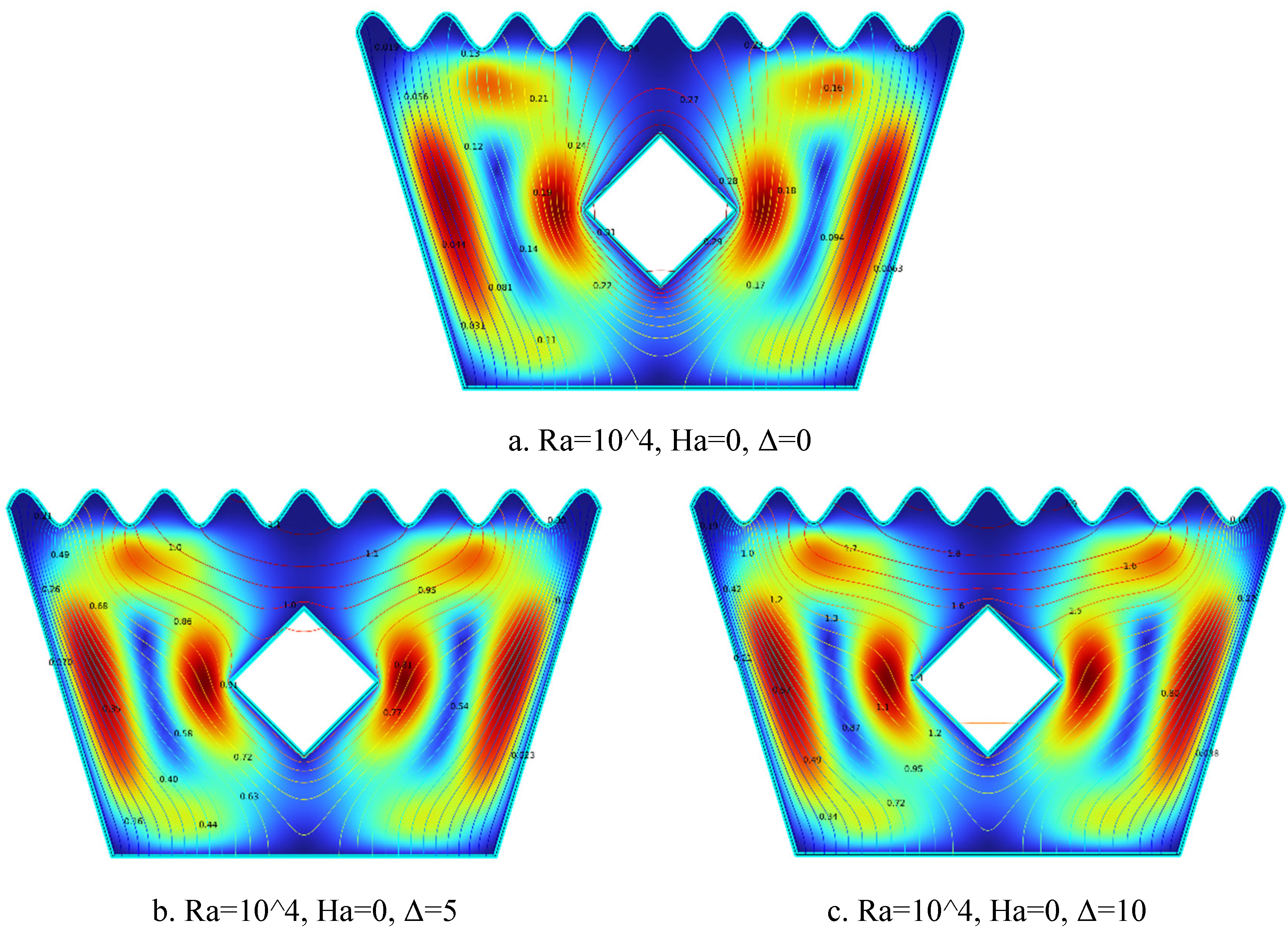
The streamline plots in Figure 5.4(a–c) demonstrate the effect of increasing internal heat generation (Δ) on flow behavior at Ra = 10⁴ and Ha = 0. In Figure 5.4(a) for Δ = 0, weak and symmetric vortices form on both sides of the heated solid block, with low-intensity flow indicating minimal natural convection in the absence of internal heating. In Figure 5.4(b) for Δ = 5, the circulation becomes stronger and more asymmetric, as moderate heat generation enhances buoyancy forces and increases flow intensity. Figure 5.4(c) for Δ = 10 shows large and vigorous vortices surrounding the block, with buoyancy-driven convection clearly dominating the flow field. As Δ increases, the buoyancy effects intensify, resulting in stronger convective currents and enhanced thermal activity throughout the cavity.
5.1.5. Streamline Plots for Ra = 104, Ha = 10, Δ=0, 5, 10
Figure 5.
5(a-c). Streamline Plots (Ra = 104, Ha = 10, Δ=0, 5, 10).
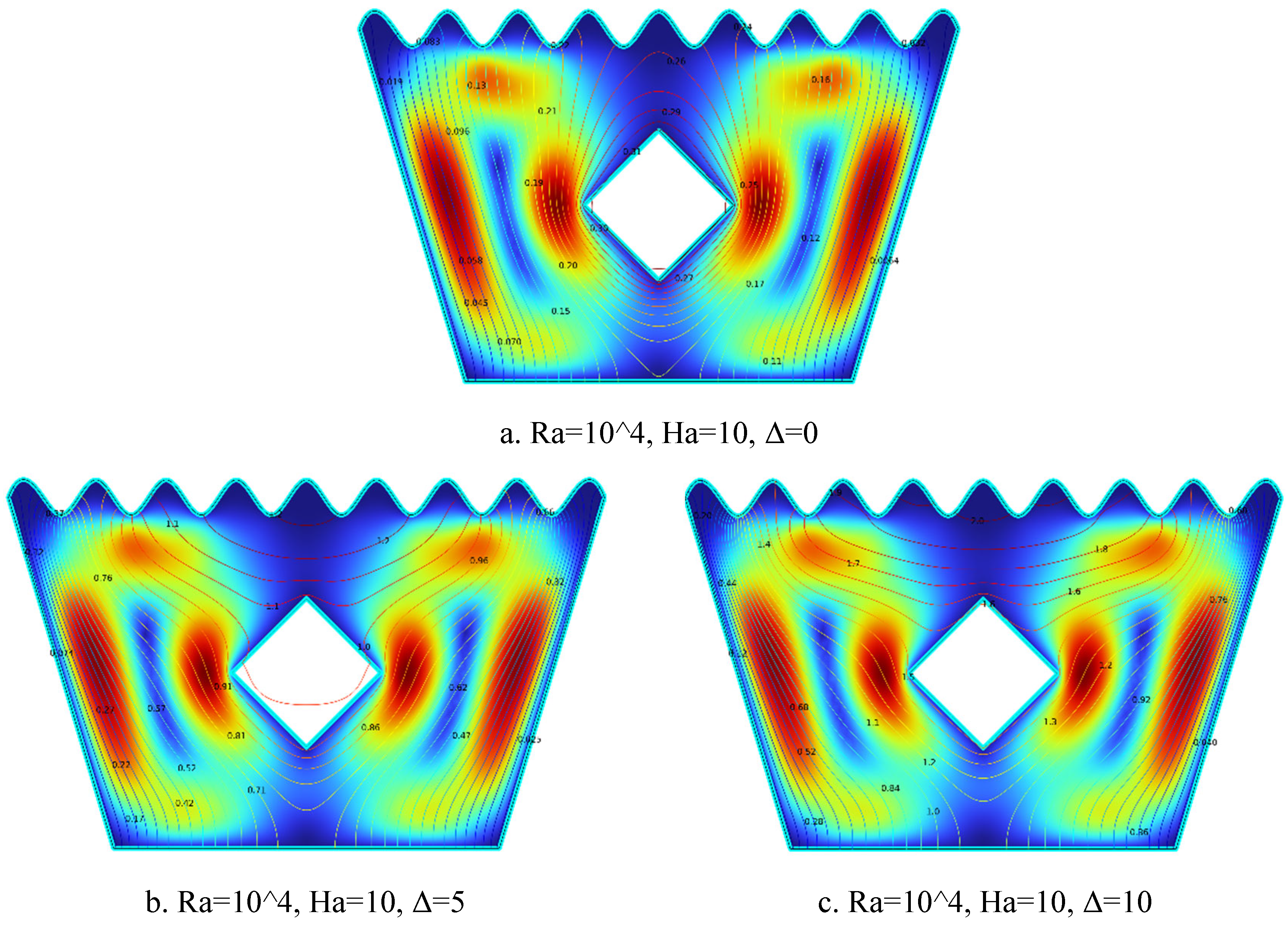
The streamline plots in Figure 5.5(a–c) illustrate the evolution of flow patterns with increasing heat generation coefficient Δ at Ra = 10⁴ and Ha = 10. In Figure 5.5(a) for Δ = 0, weak and symmetric counter-rotating vortices appear on either side of the heated solid block, with subdued flow and limited fluid interaction, reflecting minimal buoyancy-driven convection in the absence of internal heating. Figure 5.5(b) for Δ = 5 shows intensified and slightly asymmetric vortices, especially near the block corners, as moderate heat generation boosts buoyant forces and enhances flow motion. In Figure 5.5(c) for Δ = 10, the vortices become strongly intensified and well-defined, with dominant upward and outward flow around the heated block. This indicates robust natural convection and increased thermal circulation. Overall, as Δ increases, buoyancy effects strengthen, resulting in more vigorous vortical structures and enhanced fluid circulation within the MHD-influenced trapezoidal cavity.
5.1.6. Streamline Plots for Ra = 104, Ha = 20, Δ=0, 5, 10
Figure 5.
6(a-c). Streamline Plots (Ra = 104, Ha = 20, Δ=0, 5, 10).
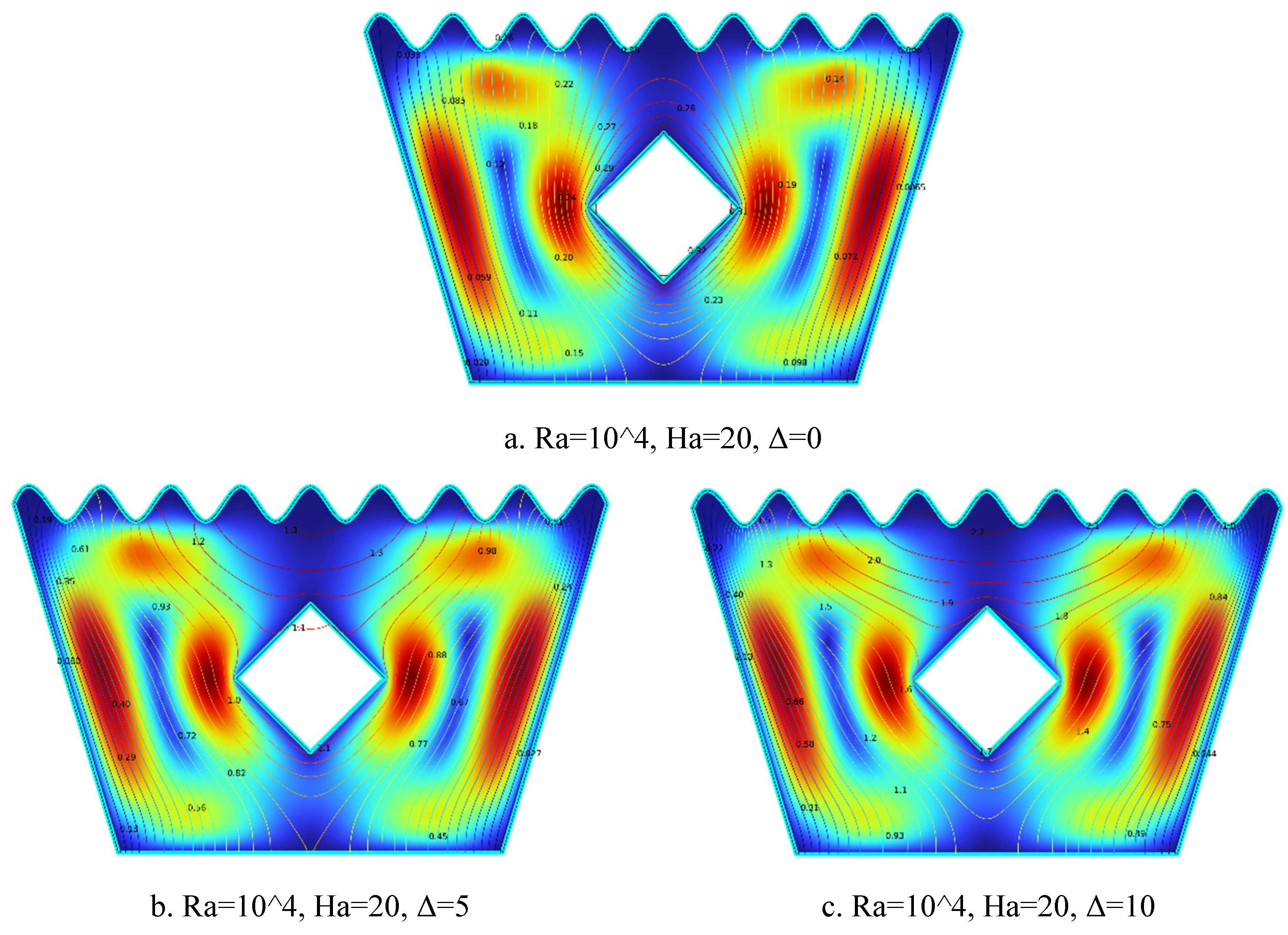
The streamline plots in Figure 5.6(a–c) depict the impact of increasing heat generation coefficient Δ on flow behavior at Ra = 10⁴ and Ha = 20. In Figure 5.6(a) for Δ = 0, weak and symmetric vortex formations appear around the solid block, with limited fluid motion due to both the absence of internal heat generation and the magnetic damping effect imposed by Ha = 20. Figure 5.6(b) for Δ = 5 shows enhanced and slightly asymmetric vortices, as moderate internal heat generation strengthens buoyancy forces, leading to more active recirculation despite magnetic suppression. In Figure 5.6(c) for Δ = 10, the flow becomes highly intensified and dynamic, with strong vortices forming around the heated block. The substantial internal heating effectively overcomes magnetic damping, significantly increasing convective activity. Overall, as Δ increases, buoyancy-driven convection becomes dominant, intensifying flow circulation even under the influence of a strong magnetic field.
5.1.7. Streamline Plots for Ra = 105, Ha = 0, Δ=0, 5, 10
Figure 5.
7(a-c). Streamline Plots (Ra = 105, Ha = 0, Δ=0, 5, 10).
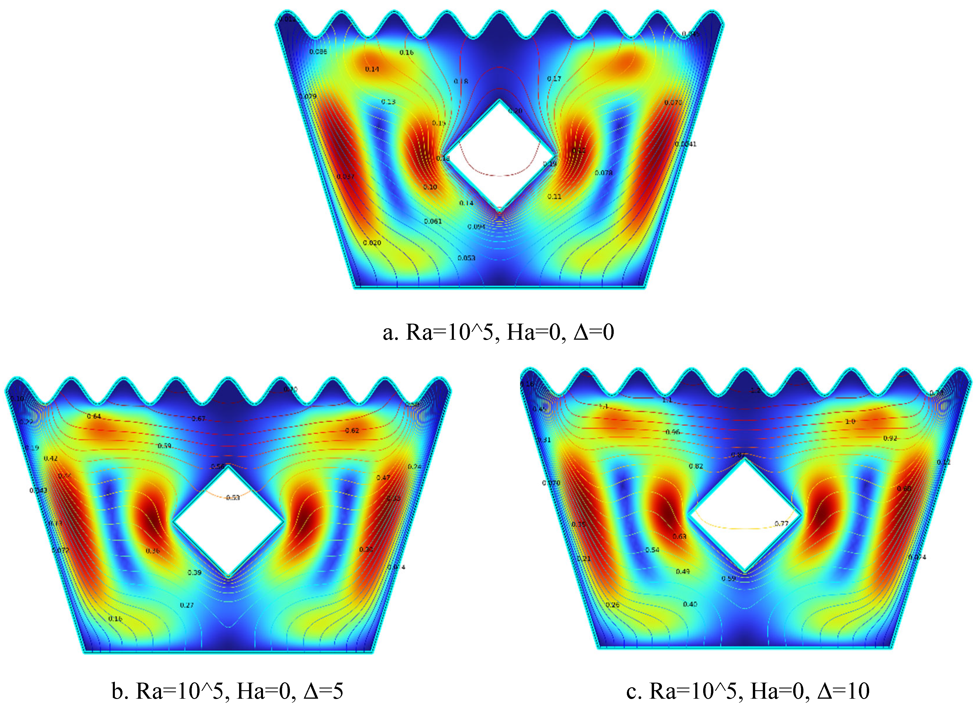
The streamline plots in Figure 5.7(a–c) illustrate the effect of increasing internal heat generation coefficient Δ on flow behavior at Ra = 10⁵ and Ha = 0. In Figure 5.7(a) for Δ = 0, symmetric but relatively weak vortices are observed on both sides of the solid block, with smooth and steady flow indicating moderate circulation due to the absence of internal heating. Figure 5.7(b) for Δ = 5 displays stronger vortices and noticeable asymmetry, as the introduction of internal heat generation enhances buoyancy forces and increases flow intensity around the block. In Figure 5.7(c) for Δ = 10, well-defined and intensified vortices form with tighter streamlines and higher velocity gradients, reflecting dominant natural convection. As Δ increases, the buoyancy-driven flow strengthens, resulting in more vigorous and complex convective flow structures within the cavity.
5.1.8. Streamline Plots for Ra = 105, Ha = 10, Δ=0, 5, 10
Figure 5.
8(a-c). Streamline Plots (Ra = 105, Ha = 10, Δ=0, 5, 10).
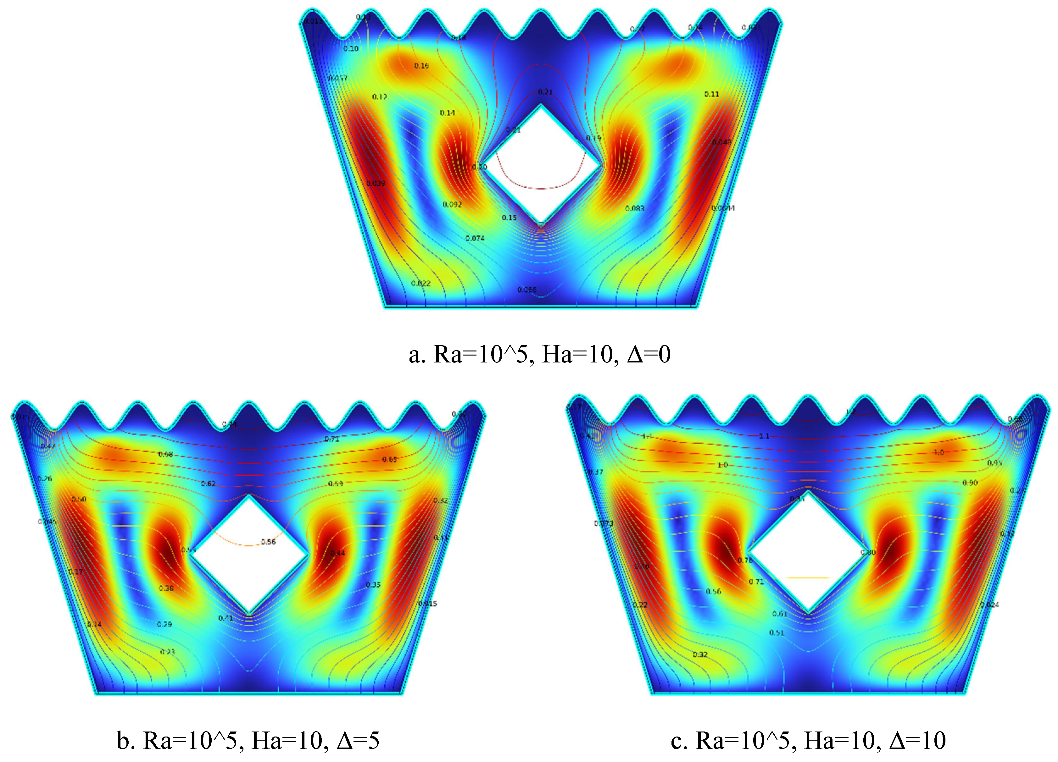
The streamline plots in Figure 3.8(a–c) depict the impact of increasing internal heat generation coefficient Δ on the flow behavior at Ra = 10⁵ and Ha = 10. In Figure 5.8(a) for Δ = 0, symmetric and relatively moderate vortices form on both sides of the heated block, with low velocity gradients and subdued convection due to the absence of internal heat generation. Figure 5.8(b) for Δ = 5 shows visibly stronger and slightly asymmetric vortices, where the moderate internal heating enhances buoyancy-driven flow, resulting in upward fluid motion and intensified circulation around the block. In Figure 5.8(c) for Δ = 10, the vortices become significantly more intense, with clearly defined flow paths and stronger velocity gradients, indicating vigorous natural convection. As Δ increases, thermal buoyancy becomes more dominant, enhancing convective currents and creating more energetic and complex streamline patterns within the cavity.
5.1.9. Streamline Plots for Ra = 105, Ha = 20, Δ=0, 5, 10
Figure 5.
9(a-c). Streamline Plots (Ra = 105, Ha = 20, Δ=0, 5, 10).
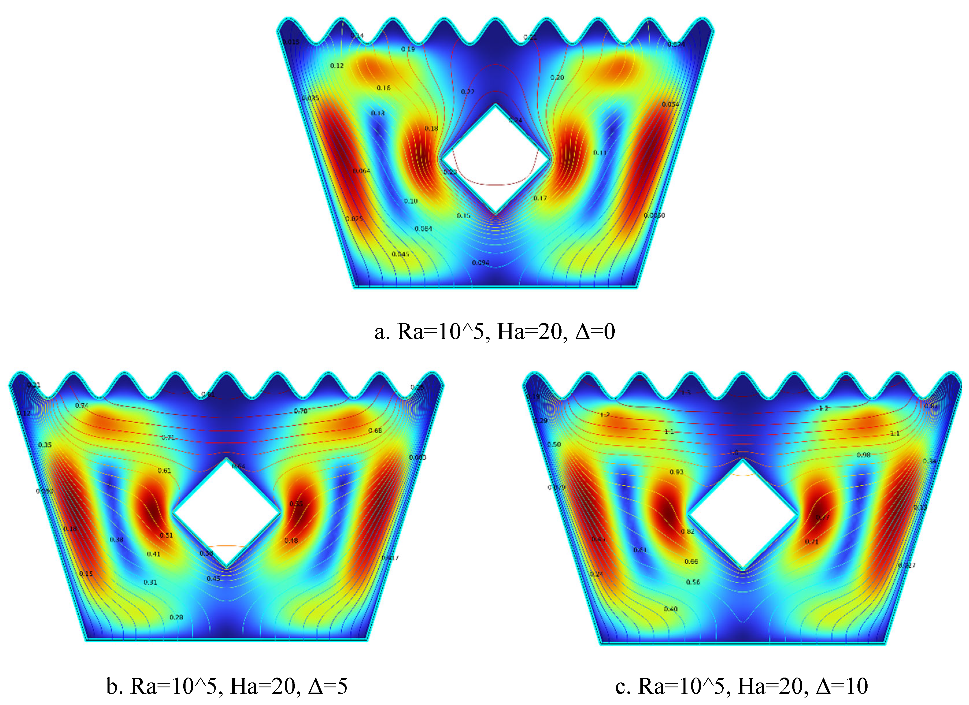
The streamline plots in Figure 5.9(a–c) illustrate the evolution of flow behavior with increasing internal heat generation coefficient Δ at Ra = 10⁵ and Ha = 20. In Figure 5.9(a) for Δ = 0, weak and symmetric vortices appear on both sides of the solid block, with low circulation levels, reflecting suppressed flow due to the strong magnetic field and lack of internal heat generation. Figure 5.9(b) for Δ = 5 shows stronger and slightly asymmetric vortices, where moderate internal heating enhances buoyancy forces and increases fluid motion around the heated block. In Figure 5.9(c) for Δ = 10, the vortex structures become intensified and dominant, with flow wrapping and tilting upward around the block, indicating that strong ”atur’l convection is overcoming magnetic damping. As Δ increases, buoyancy effects begin to dominate, resulting in greater convection strength and intensified circulation around the heated square block.
5.2. Isotherm Analysis
5.2.1. Isotherm Plots for Ra = 10³, Ha = 0, Δ=0, 5, 10
Figure 6.
1(a-c). Isotherm Plots (Ra = 103, Ha = 0, Δ=0, 5, 10)).
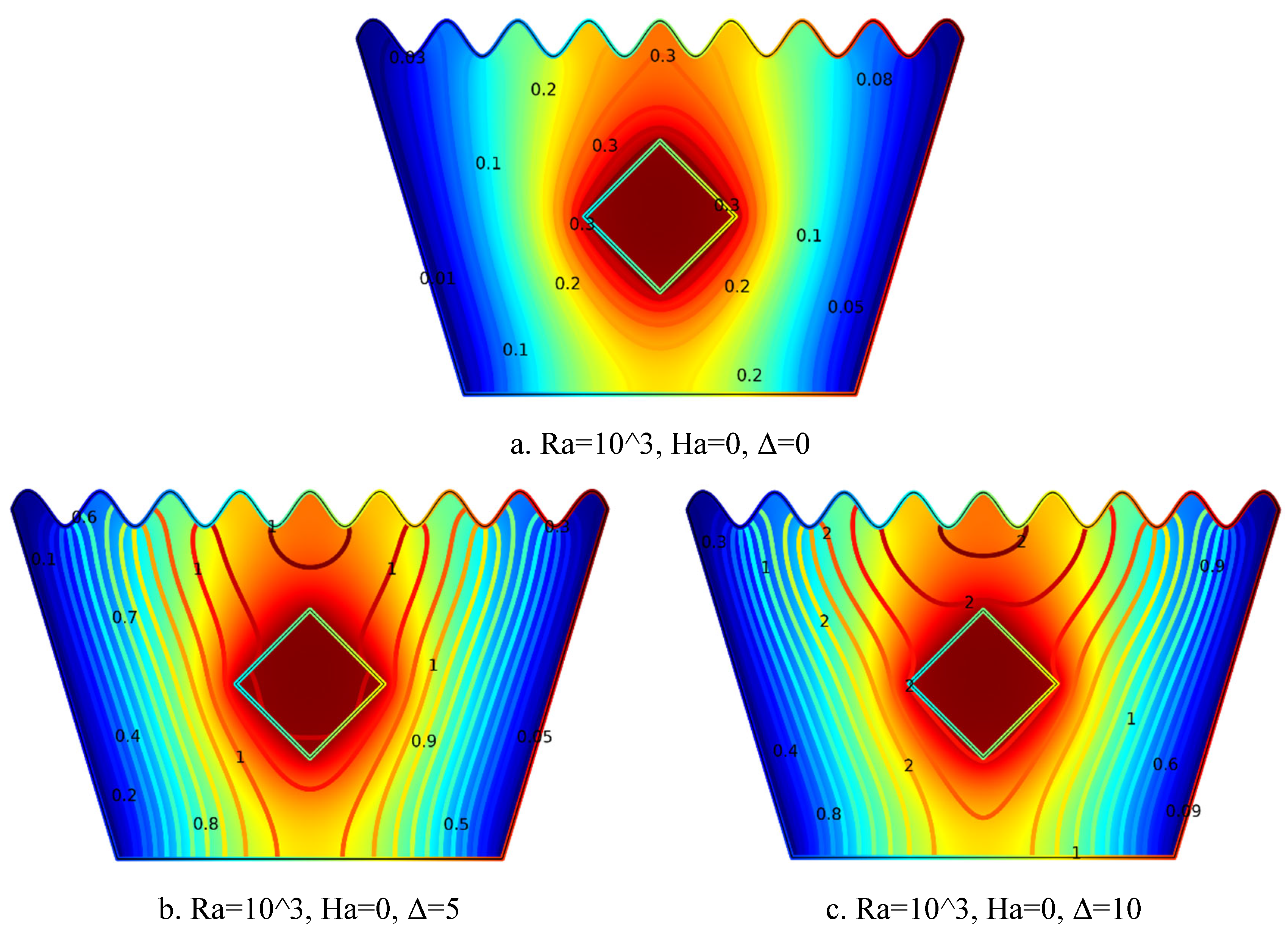
The isotherm plots in Figure 6.1(a–c) illustrate the effect of increasing internal heat generation coefficient Δ on the temperature distribution within the cavity. In Figure 6.1(a) for Δ = 0, the temperature field appears smooth and symmetric around the heated square block, dominated by conduction with weak temperature gradients across the domain. Figure 6.1(b) for Δ = 5 shows denser and upward-stretching isotherms, indicating the onset of buoyancy-driven convection due to moderate internal heating. In Figure 6.1(c) for Δ = 10, the isotherms become highly compressed and strongly inclined upward around the block, highlighting intense heat transfer and dominant natural convection. As Δ increases, the isotherm plots reflect greater thermal stratification and nonlinear temperature distribution, underscoring the significant influence of internal heat generation on the overall thermal field.
5.2.2. Isotherm Plots for Ra = 10³, Ha = 10, Δ=0, 5, 10
Figure 6.
2(a-c). Isotherm Plots (Ra = 103, Ha = 10, Δ=0, 5, 10).
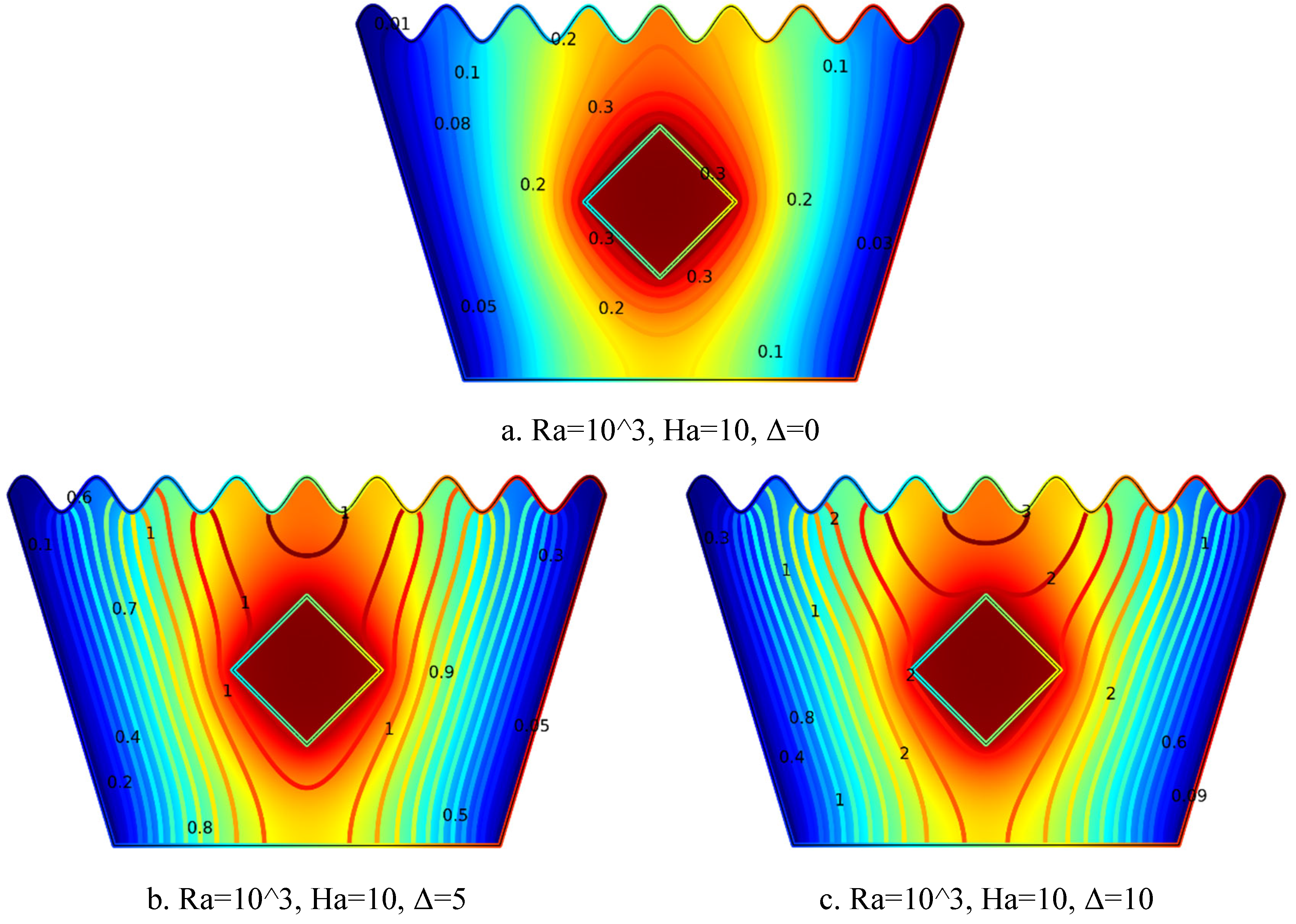
The isotherm plots in Figure 6.2(a–c) for Ra = 10³ and Ha = 10 illustrate how the thermal field evolves with increasing heat generation coefficient (Δ). In Figure 6.2(a) for Δ = 0, the isotherms are symmetric and evenly spaced around the heated block, indicating conduction-dominated heat transfer in the absence of internal heat generation. Figure 6.2(b) for Δ = 5 reveals denser isotherms and noticeable curvature near the block, reflecting enhanced thermal gradients and the onset of buoyancy-driven convection. In Figure 6.2(c) for Δ = 10, the isotherms become more intensified and extend outward, signifying a substantial temperature rise and stronger convective heat transfer due to high internal heating. Overall, as Δ increases, the thermal field becomes more intense, and convective heat transfer is significantly promoted.
5.2.3. Isotherm Plots for Ra = 10³, Ha = 20, Δ=0, 5, 10
Figure 6.
3(a-c). Isotherm Plots (Ra = 10³, Ha = 20, Δ=0, 5, 10).
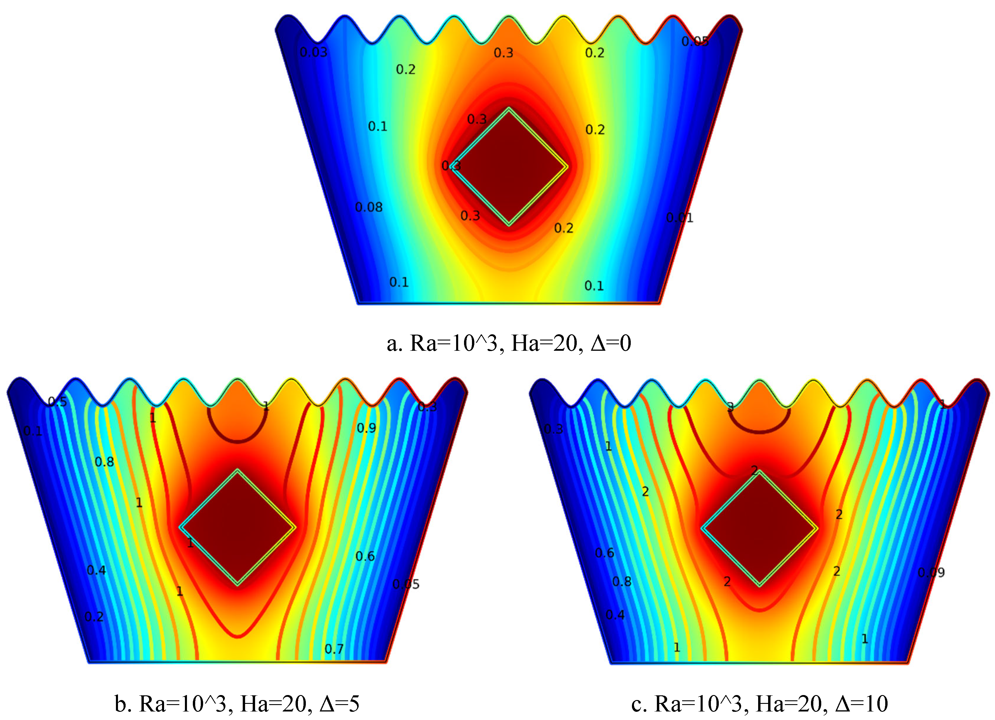
The isotherm plots in Figure 6.3(a–c) highlight the effect of increasing internal heat generation coefficient Δ on the thermal behavior at Ra = 10³ and Ha = 20. Figure 6.3(a) for Δ = 0 exhibits nearly symmetric and evenly spaced isotherms around the solid block, indicating conduction-dominated heat transfer in the absence of internal heating. In Figure 6.3(b) for Δ = 5, the isotherms become denser and more distorted near the heated region, signifying stronger thermal gradients and the emergence of convective effects. Figure 6.3(c) for Δ = 10 shows tightly packed and outward-stretching contours, representing a significant increase in temperature and vigorous convective heat transfer driven by higher internal heat generation. Overall, increasing Δ intensifies the thermal field and enhances convective behavior throughout the cavity.
5.2.4. Isotherm Plots for Ra = 104, Ha = 0, Δ=0, 5, 10
Figure 6.
4(a-c). Isotherm Plots (Ra = 104, Ha = 0, Δ=0, 5, 10).
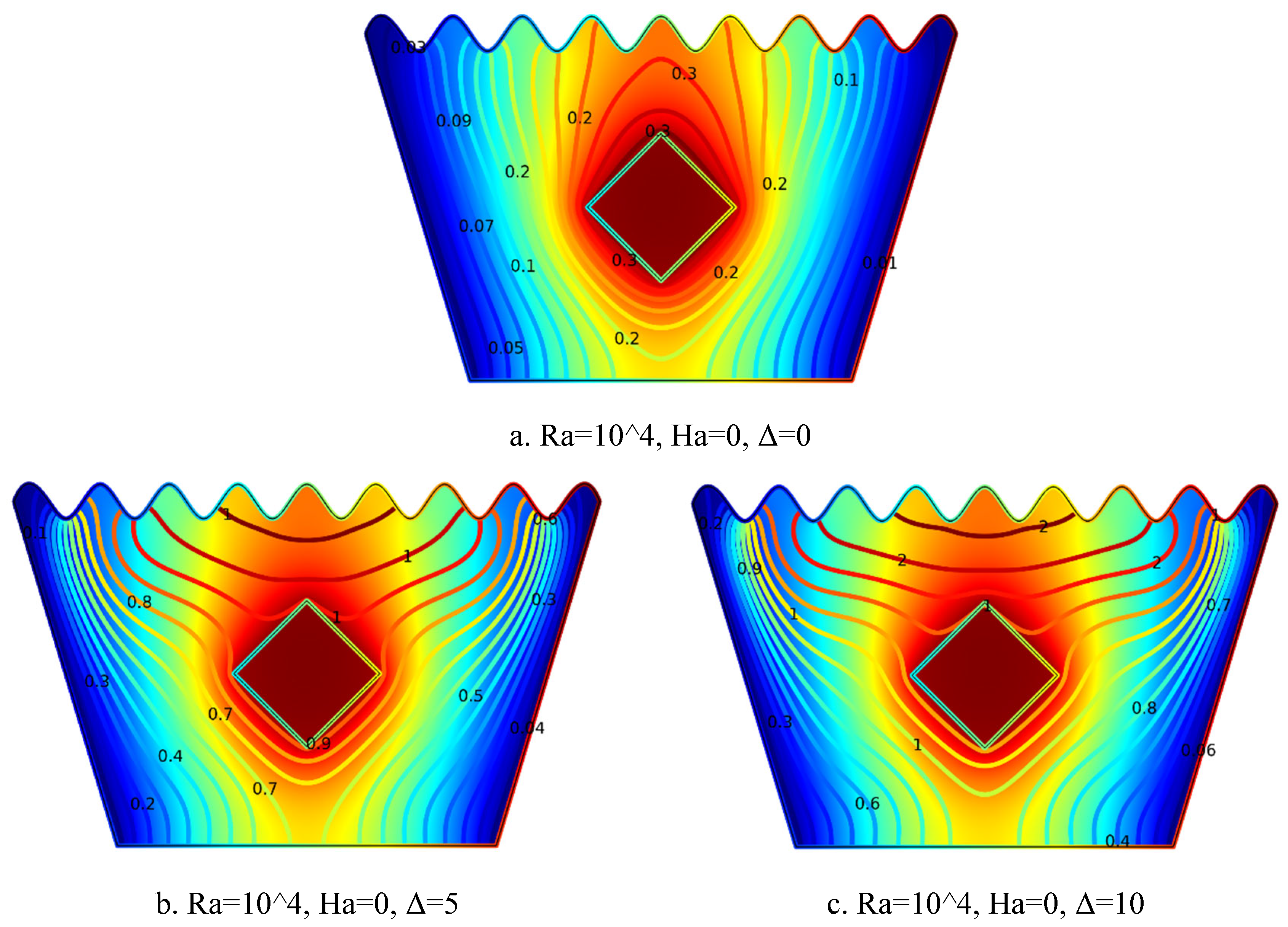
The isotherm plots in Figure 6.4(a–c) illustrate the thermal response within the cavity at Ra = 10⁴ and Ha = 0 as the internal heat generation coefficient Δ increases. In Figure 6.4(a) for Δ = 0, symmetric and smoothly distributed temperature contours surround the heated square block, indicating that heat transfer is primarily governed by conduction due to the absence of internal heating. Figure 6.4(b) for Δ = 5 shows tighter and more distorted isotherms concentrated near the block, reflecting stronger thermal gradients and the onset of buoyancy-driven convection. In Figure 6.4(c) for Δ = 10, the isotherms become more concentrated and spread outward, highlighting a higher temperature rise and significantly intensified convective heat transfer driven by strong internal heat generation. Overall, as Δ increases, the thermal field becomes more vigorous, and convective activity is notably enhanced.
5.2.5. Isotherm Plots for Ra = 104, Ha = 10, Δ=0, 5, 10
Figure 6.
5(a-c). Isotherm Plots (Ra = 104, Ha = 10, Δ=0, 5, 10).
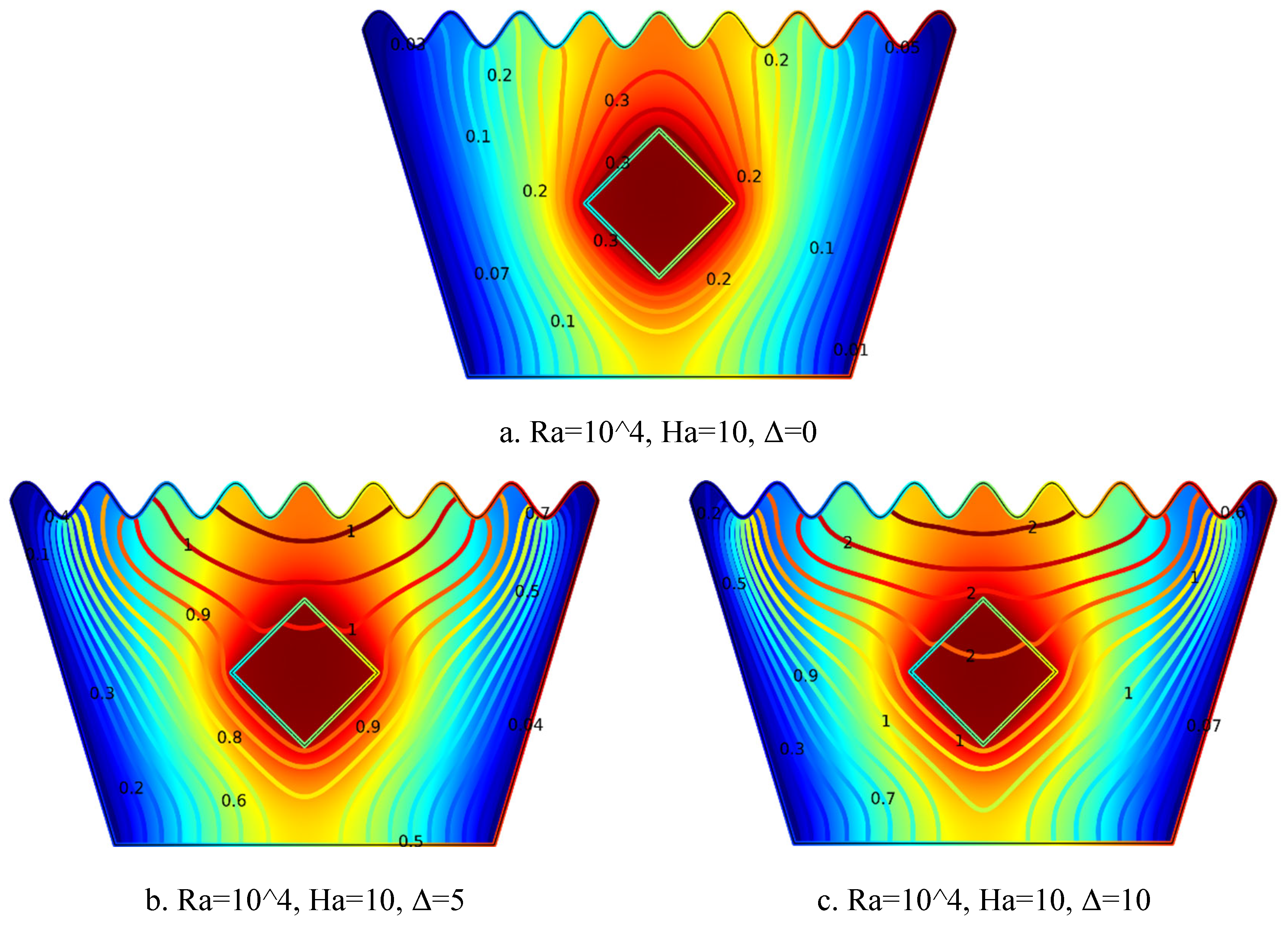
The isotherm plots in Figure 6.5(a–c) illustrate the effect of increasing internal heat generation coefficient Δ on the thermal field at Ra = 10⁴ and Ha = 10. In Figure 6.5(a) for Δ = 0, the temperature contours are symmetric and nearly parallel around the heated square block, indicating a conduction-dominated regime with minimal thermal activity. Figure 6.5(b) for Δ = 5 shows denser and more curved isotherms near the block, reflecting enhanced thermal gradients and the onset of convective motion due to moderate internal heat generation. In Figure 6.5(c) for Δ = 10, the isotherms become highly concentrated and spread broadly from the block, signifying a substantial rise in temperature and stronger convective heat transfer. Overall, as Δ increases, the thermal field becomes more intense, facilitating more vigorous heat transport within the cavity.
5.2.6. Isotherm Plots for Ra = 104, Ha = 20, Δ=0, 5, 10
Figure 6.
6(a-c). Isotherm Plots (Ra = 104, Ha = 20, Δ=0, 5, 10).
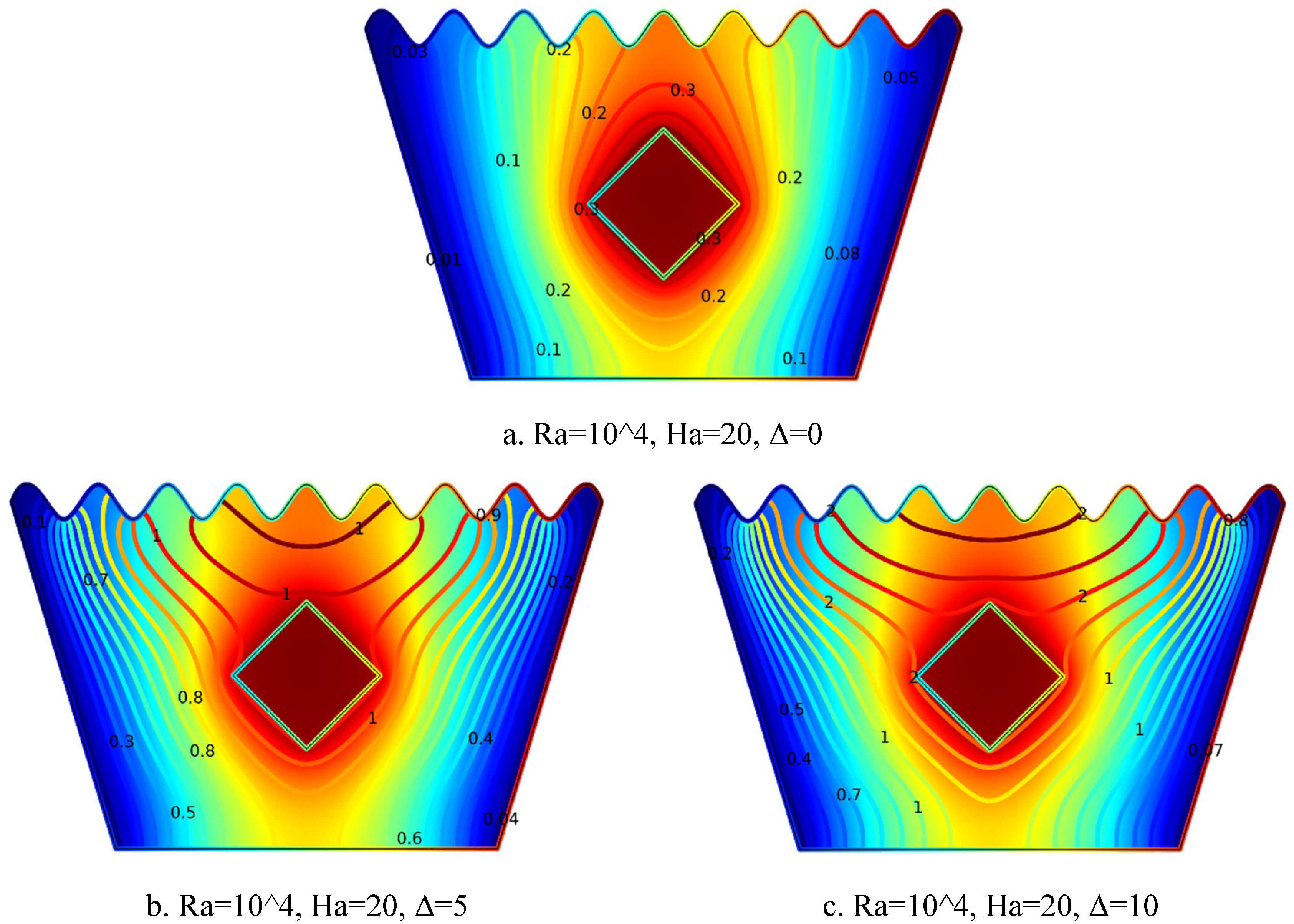
The isotherm plots in Figure 6.6(a–c) demonstrate the impact of increasing internal heat generation coefficient Δ on thermal behavior at Ra = 10⁴ and Ha = 20. In Figure 6.6(a) for Δ = 0, symmetric and uniformly spaced isotherms surround the heated square block, indicating conduction-dominated heat transfer in the absence of internal heating. Figure 6.6(b) for Δ = 5 shows denser and more curved isotherms near the block, reflecting increased thermal gradients and the emergence of buoyancy-driven convection due to moderate heat generation. In Figure 6.6(c) for Δ = 10, the isotherms become tightly packed and spread outward, signifying a substantial temperature rise and intensified convective heat transfer. Overall, as Δ increases, the thermal field intensity grows significantly, enhancing convective activity throughout the cavity.
5.2.7. Isotherm Plots for Ra = 105, Ha = 0, Δ=0, 5, 10
Figure 6.
7(a-c). Isotherm Plots (Ra = 105, Ha = 0, Δ=0, 5, 10).
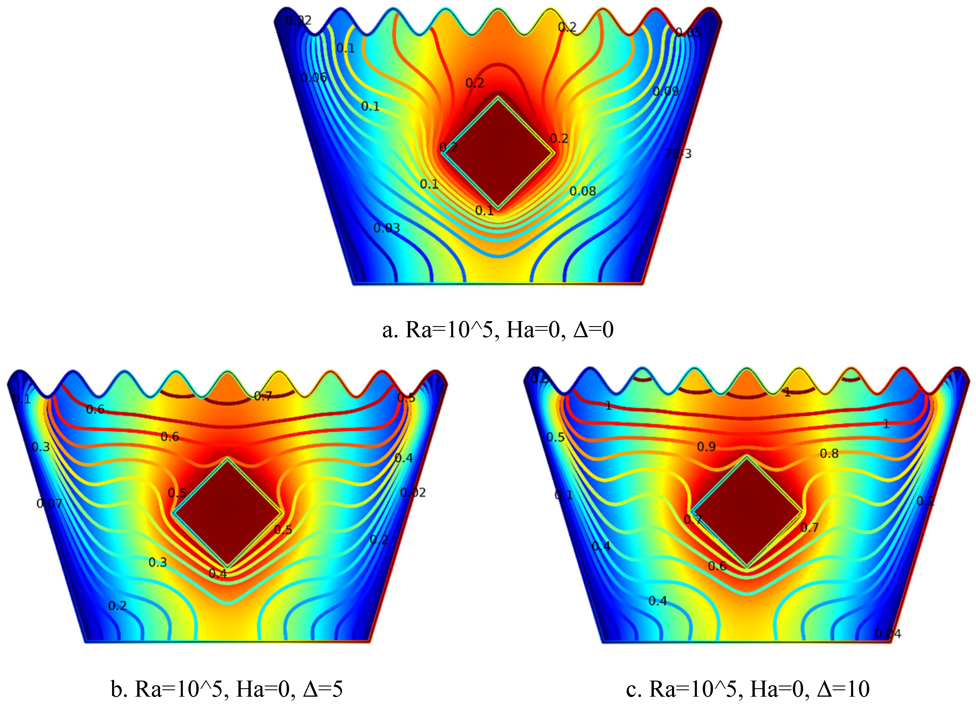
The isotherm plots in Figure 6.7(a–c) illustrate the influence of increasing internal heat generation coefficient Δ on the thermal distribution at Ra = 10⁵ and Ha = 0. In Figure 6.7(a) for Δ = 0, the isotherms are symmetric and compact around the heated solid block, indicating a conduction-dominated heat transfer regime with minimal thermal activity. Figure 6.7(b) for Δ = 5 reveals more curved and denser isotherms surrounding the block, marking the onset of buoyancy-driven convection as moderate heat generation enhances thermal gradients. In Figure 6.7(c) for Δ = 10, the thermal contours are highly intensified and spread outward, showing a significant rise in temperature and stronger convective heat transfer. Overall, as Δ increases, the thermal field becomes more dynamic, significantly boosting heat transfer efficiency within the cavity.
5.2.8. Isotherm Plots for Ra = 105, Ha = 10, Δ=0, 5, 10
Figure 6.
8(a-c). Isotherm Plots (Ra = 105, Ha = 10, Δ=0, 5, 10).
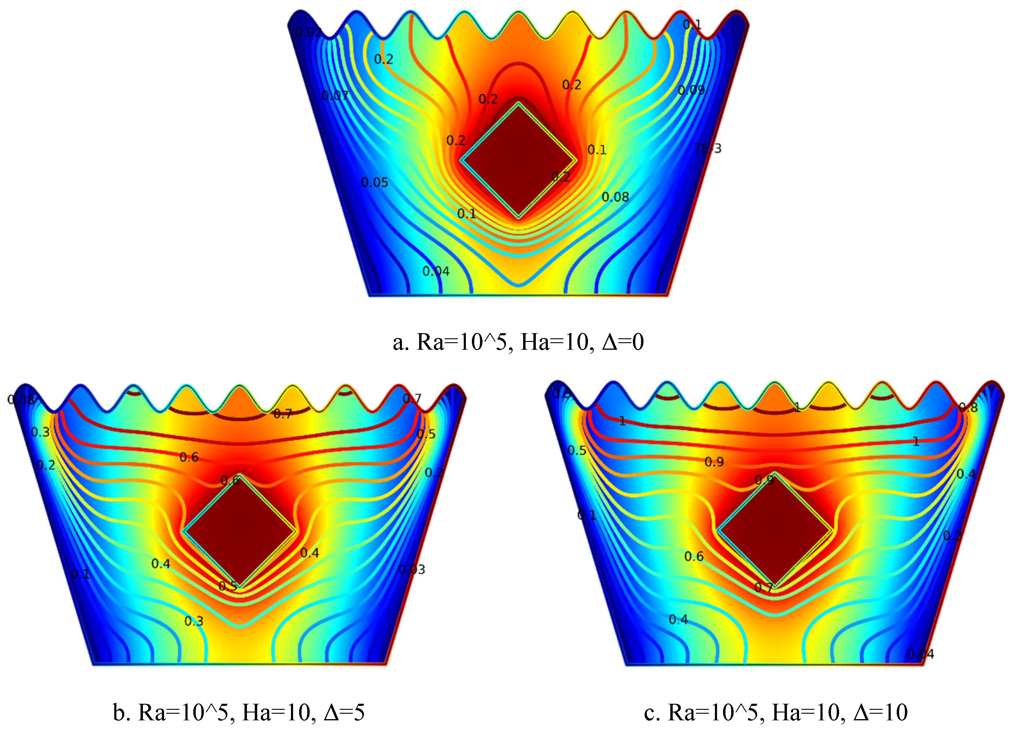
The isotherm plots in Figure 6.8(a–c) demonstrate the effect of increasing internal heat generation coefficient Δ on the thermal field at Ra = 10⁵ and Ha = 10. In Figure 6.8(a) for Δ = 0, symmetrical and nearly parallel isotherms are concentrated around the heated block, indicating conduction-dominated heat transfer with minimal buoyancy-driven flow due to the absence of internal heating. Figure 6.8(b) for Δ = 5 reveals increased curvature and denser isotherms near the block, reflecting steeper temperature gradients and the initiation of convection currents caused by moderate internal heat generation. In Figure 6.8(c) for Δ = 10, the isotherms become significantly intensified and extend outward from the block, indicating strong thermal gradients and vigorous natural convection. Overall, as Δ increases, the thermal field intensifies, buoyancy effects strengthen, and convective heat transfer becomes more prominent.
5.2.9. Isotherm Plots for Ra = 105, Ha = 20, Δ=0, 5, 10
Figure 6.
9(a-c). Isotherm Plots (Ra = 105, Ha = 20, Δ=0, 5, 10).
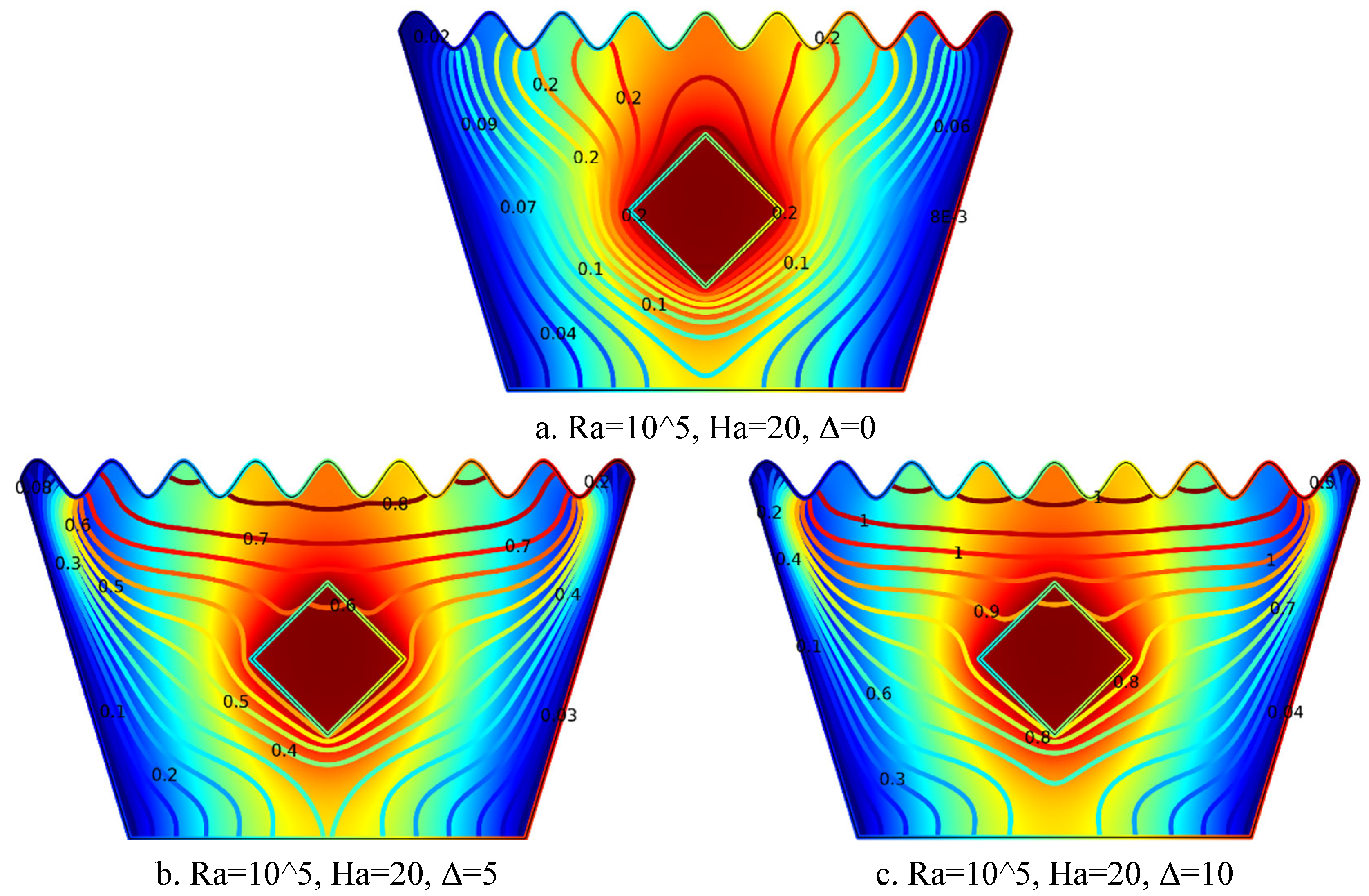
The isotherm plots in Figure 6.9(a–c) depict the thermal behavior within the cavity at Ra = 10⁵ and Ha = 20 for varying internal heat generation coefficient Δ. In Figure 6.9(a) for Δ = 0, the isotherms are largely symmetric and evenly spaced around the heated square block, reflecting a conduction-dominated regime with minimal thermal activity due to the absence of internal heat generation. Figure 6.9(b) for Δ = 5 shows denser and more distorted isotherms near the block, indicating stronger thermal gradients and the onset of buoyancy-driven convection induced by moderate heat generation. In Figure 6.9(c) for Δ = 10, the thermal contours become more pronounced and widely spread, demonstrating a significant temperature rise and intensified convective heat transfer. Overall, increasing Δ markedly amplifies the thermal field intensity and enhances convective effects throughout the cavity.
5.3. Average Nu vs Ra Graph Analysis
The graphs in Figs. 7.1, 7.2, and 7.3 illustrate the variation of the average Nusselt number (Nu) with the Rayleigh number (Ra) for different Hartmann numbers (Ha = 0, 10, 20) and heat generation coefficients (Δ = 0, 5, 10).
In Figure 7.1 (Δ = 0), Nu increases sharply with Ra, with Ha = 0 showing the highest heat transfer rate due to the absence of magnetic suppression. As Ha increases, the Nu decreases, indicating that stronger magnetic fields suppress convective heat transfer. In Figure 7.2 (Δ = 5), the overall Nu values are lower than in Figure 5.1, but the trend remains: increasing Ra enhances Nu, while increasing Ha suppresses it. The impact of Δ becomes more apparent in Figure 7.3 (Δ = 10), where the Nu values are further reduced due to dominant internal heat generation, which alters the temperature distribution and reduces the overall temperature gradient near the heated surface. Across all three figures, higher Ra leads to enhanced convection, but increased Ha and Δ reduce the average Nu, highlighting the complex interplay between buoyancy, magnetic damping, and internal heat generation.
Figure 7.
1. Average Nusselt number (Nu) vs Rayleigh number (Ra) (H=0,10,20, Δ=0).
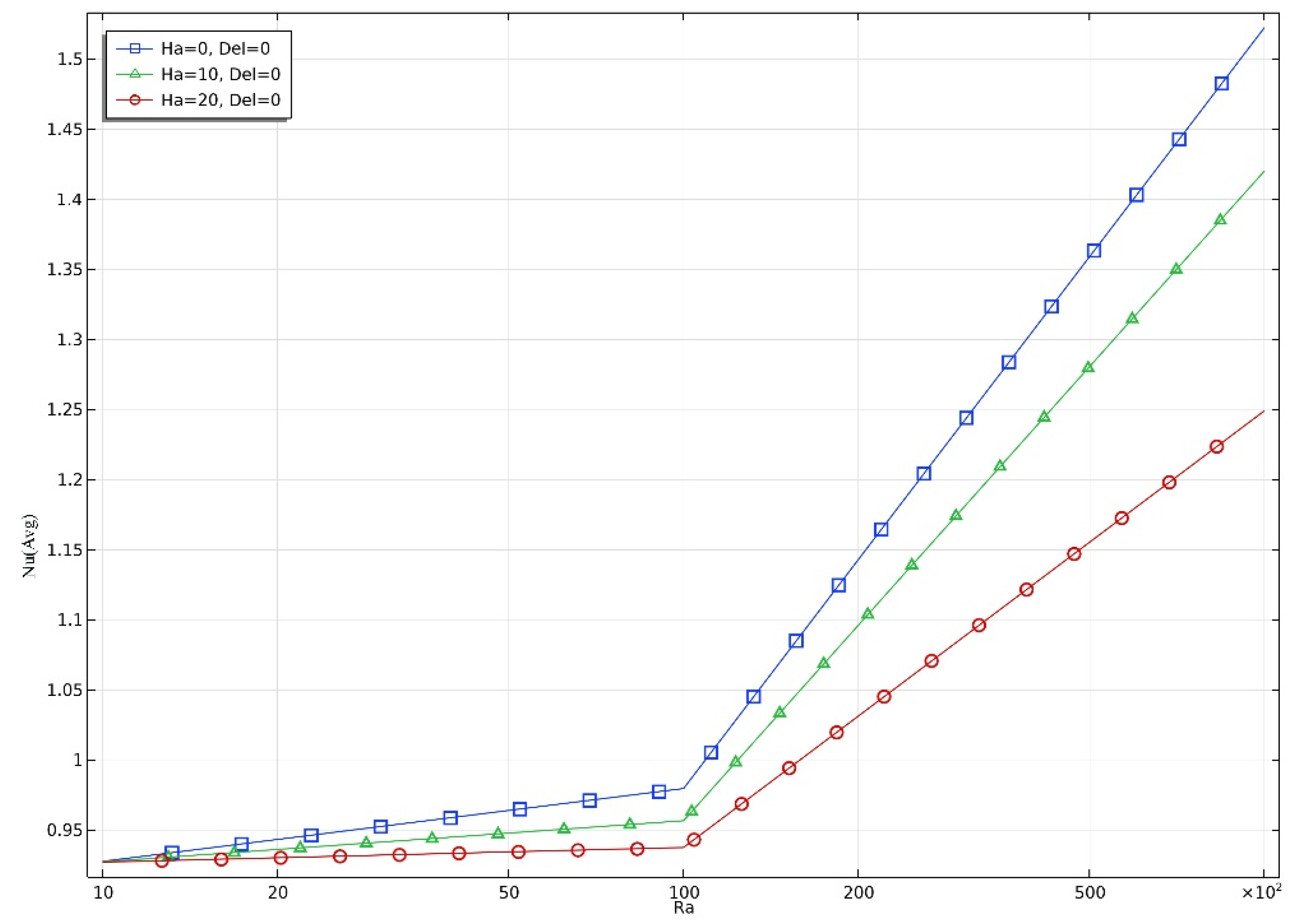
Figure 7.
2. Average Nusselt number (Nu) vs Rayleigh number (Ra) (H=0,10,20, Δ=5).
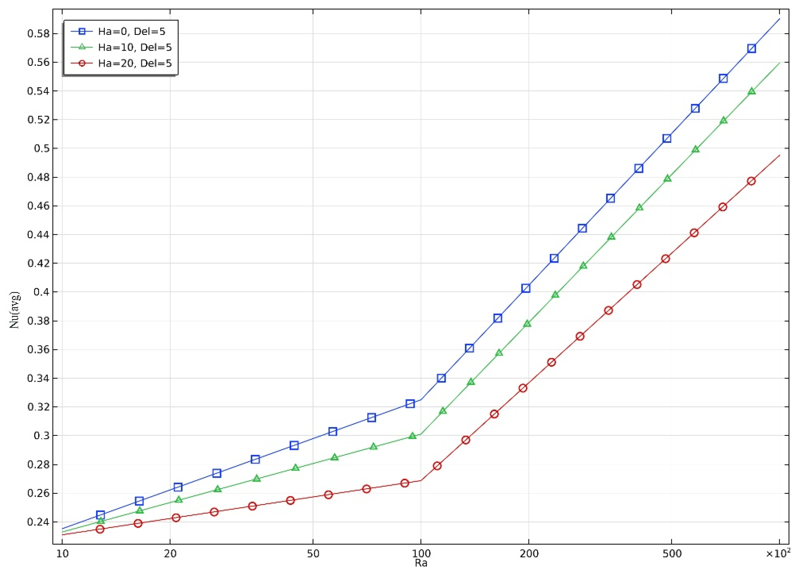
Figure 7.
3. Average Nusselt number (Nu) vs Rayleigh number (Ra) (H=0,10,20, Δ=5).
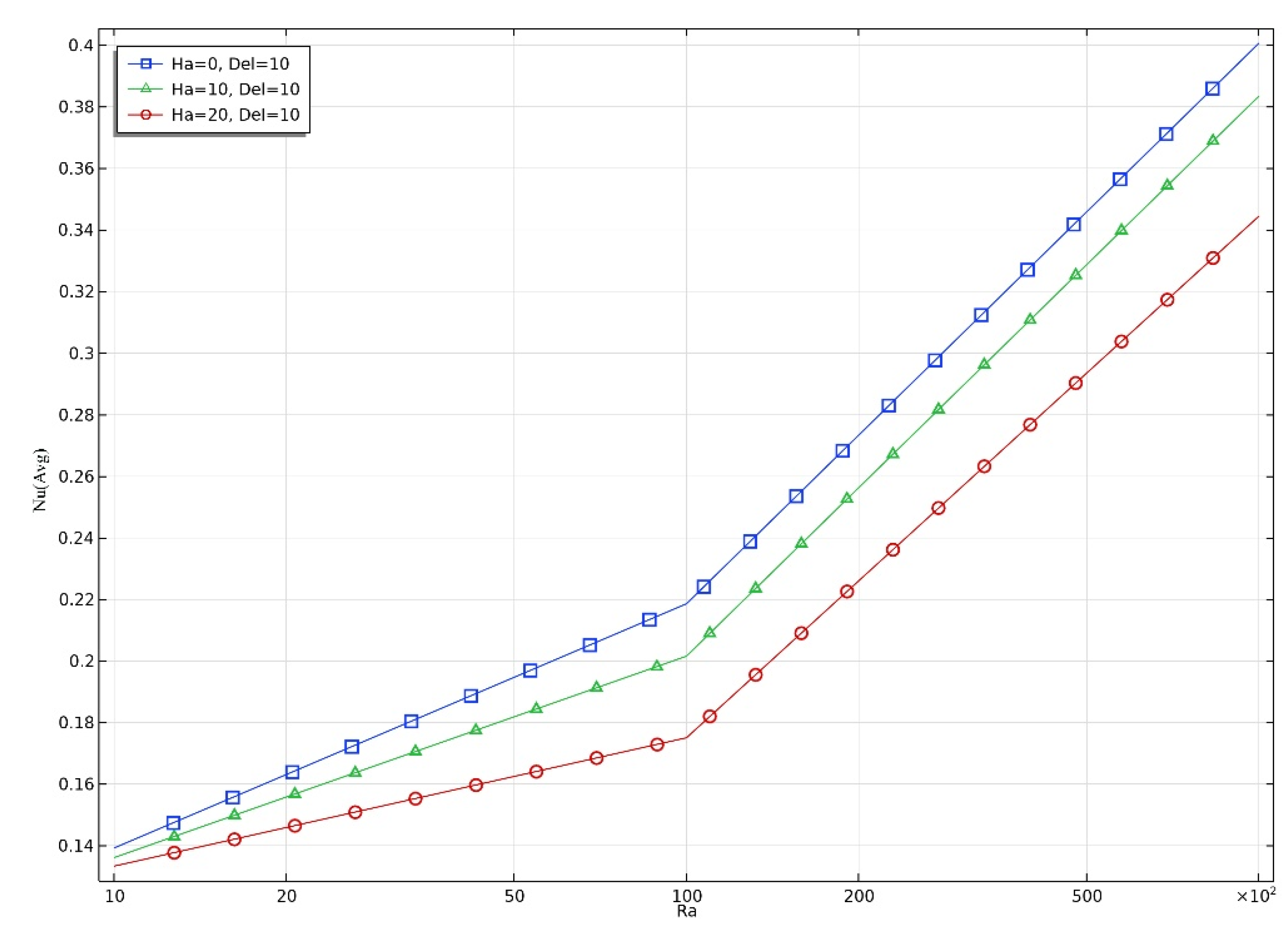
Table 3 presents the average Nusselt number (Nu) values for different Rayleigh numbers (Ra), Hartmann numbers (Ha), and heat generation coefficients (Δ). The values reflect how heat transfer performance varies under different magneto-convective conditions within the trapezoidal cavity.
For Δ = 0, the Nu values increase with Ra, highlighting that thermal convection strengthens as buoyancy forces increase. However, Nu decreases with increasing Ha, indicating that the magnetic field suppresses convection.
At Ra = 10⁵: Nu drops from 1.52 (Ha = 0) to 1.42 (Ha = 10) and then to 1.25 (Ha = 20).
For Δ = 5, Nu also rises with Ra, and again decreases as Ha increases. The presence of moderate internal heat generation slightly boosts convection compared to Δ = 0, but magnetic damping still limits the enhancement.
At Ra = 10⁵: Nu reduces from 0.59 (Ha = 0) to 0.49 (Ha = 20).
For Δ = 10, Nu values remain the lowest among the three Δ cases, despite increasing Ra. This indicates that high internal heat generation dominates the flow structure, reducing the temperature gradient across the cavity wall and thus lowering average Nu. The effect of Ha is again inhibitory to heat transfer.
At Ra = 10⁵: Nu is 0.40 for Ha = 0 and decreases to 0.34 for Ha = 20.
The table clearly demonstrates that increasing Ra enhances heat transfer, while increasing Ha suppresses it due to magnetic damping. As Δ increases, the average Nu reduces, indicating that excessive internal heat generation may weaken wall heat transfer by reducing thermal gradients.
6. Conclusions
This study comprehensively evaluates the thermal performance of a heat-generating fluid within a magnetohydrodynamic (MHD)-influenced wavy trapezoidal cavity containing a centrally located heated solid square block. The findings from Streamline Analysis reveal that increasing the internal heat generation coefficient (Δ) intensifies buoyancy-driven flow, resulting in stronger and more asymmetric vortices around the block. However, a higher Hartmann number (Ha) suppresses this convection due to magnetic damping effects. From Isotherm Analysis, it is observed that as Δ increases, isotherms become increasingly distorted and concentrated near the heated block, indicating enhanced convective heat transfer and elevated thermal gradients. Yet, the presence of a strong magnetic field (higher Ha) smoothens these isotherms, showing reduced thermal agitation. The average Nusselt number supports these observations—Nu increases with Rayleigh number (Ra) due to stronger buoyancy forces, but decreases with increasing Ha and Δ. High internal heat generation reduces the wall-to-fluid temperature difference, thereby lowering Nu despite intensified internal circulation. Overall, the study concludes that while internal heat generation enhances thermal circulation, it can diminish external wall heat transfer efficiency. Additionally, increasing magnetic field strength consistently suppresses both flow and heat transfer within the cavity.
Declaration of competing interest
The authors declare that they have no known competing financial interests or personal relationships that could have appeared to influence the work reported in this paper.
Data availability
Data will be made available on request.
References
- Hasan Nahid, Deb Niloy, Saha Sumon. MHD convection with Joule heating and internal heat generation in a two-layer discretely heated chamber partly filled with porous medium. Int J Energy Res. 2024; 2024: 1720993. [CrossRef]
- Hasan Nahid, Saha Sumon. MHD conjugate mixed convection along with internal heat generation and Joule heating in a closed/open cavity with rotating solid cylinder. Int J Numer Methods Heat Fluid Flow. 2024; 34(9): 3438–3461. [CrossRef]
- Mirzaei Amirmohammad, Jalili Bahram, Jalili Payam, Ganji Davood D. Free convection in a square wavy porous cavity with partly magnetic field: a numerical investigation. Sci Rep. 2024; 14: 14152. [CrossRef]
- Jumadi Azlina, Arbin Norazam, Saleh Habibis, Kechil Seripah Awang. A review of entropy generation in rectangular cavities. J Adv Res Fluid Mech Therm Sci. 2024; 115(2): 178–221. [CrossRef]
- Zemani Farah, Sabeur Amina, Ladjedel Omar, Chelih Amira. Natural convective heat transfer in a square cavity with a curved hot wall partially heated from below. Phys Fluids. 2025; 37(1): 019101. [CrossRef]
- Mustafa Ahmed W. Constructal design of parabolic enclosure under natural convection and thermal radiation. Int J Therm Sci. 2025; 210: 109616. [CrossRef]
- Rahaman Md Mahafujur, Bhowmick Sidhartha, Ghosh Bishnu Pada, Xu Feng, Mondal Rabindra Nath, Saha Suvash C. Transient natural convection flows and heat transfer in a thermally stratified air-filled trapezoidal cavity. Therm Sci Eng Prog. 2024; 47: 102377. [CrossRef]
- Olayemi Olalekan Adebayo, Mustapha Faith Oluwasegun, Ibitoye Segun Emmanuel, Obalalu Adebowale Martins, Al-Farhany Khaled, Khan Umair. Natural convective heat transfer in trapezoidal enclosure containing a concentric elliptical cylinder. J Therm Anal Calorim. 2024; 149: 15353–15369. [CrossRef]
- Mohebbi Rasul, Ma Yuan, Soleymani Peyman. Investigating the impact of sinusoidal walls on fluid flow and heat transfer performance of C-shaped cavity. Iran J Sci Technol Trans Mech Eng. 2024. [CrossRef]
- Yaseen Duna T, Majeed Amani J, Ahmed Sahib S, Ismael Muneer A. Impact of a wavy wall triangular porous cylinder on diffusive-mixed convection in a lid-driven triangular cavity. Int J Thermofluids. 2025; 25: 101007. [CrossRef]
- Alhasan Muhammed, Hamzah Hudhaifa, Tumse Sergen, Daabo Ahmed M, Sahin Besir. Heat transfer and entropy generation in oscillating lid-driven heat sinks with variable fin configurations. Int Commun Heat Mass Transf. 2024; 159: 108264. [CrossRef]
- Daiz Abdelhak, Hidki Rachid, Fares Redouane, Charqui Zouhair. Finite element method (FEM) analysis of heat transfer by natural convection in a circular cavity containing a corrugated hollow cylinder. Int J Numer Methods Heat Fluid Flow. 2024; 34(11): 4159–4178. [CrossRef]
- Sultan Hakim S, Ali Mohammed Hasan, Shafi Jana, Fteiti Mehdi, Baro Manuel, Almutairi Khalid, Islam Mohammad S, Harb Kamal, Alharbi Fawaz S, Ghalambaz Mohammad. Design improvement of latent heat thermal energy storage in wavy channel enclosures using neural networks. J Energy Storage. 2024; 79: 110061. [CrossRef]
- Khan Noor Zeb, Bilal Sardar, Riaz Arshad, Taseer Muhammad. Coupled effects of variable permeability and adiabatic undulating walls on natural convective flow in a trapezoidal cavity: Finite element analysis. Results Phys. 2024; 56: 107267. [CrossRef]
- Khan Zafar Hayat, Yang Zhiquan, Khan Waqar A, Sheremet Mikhail A, Wu Weifen. Computational investigation of magnetohydrodynamic convective flow in a trapezoidal cavity with multiple obstacles via finite element analysis. Therm Sci Eng Prog. 2024; 50: 102570. [CrossRef]
- Ahmed Prince Hasib, Hasan Rozin Enamul, Hasan Sagor Md Jahid, Saha Sumon. Evaluation of overall thermal performance for conjugate natural convection in a trapezoidal cavity with different surface corrugations. Int Commun Heat Mass Transf. 2022; 130: 105772. [CrossRef]
- Alam Md Shahidul, Alim M A, Mollah Md S H. Mixed magneto convection in a lid driven square enclosure with a sinusoidal vertical wall and Joule heating. Procedia Eng. 2017; 194: 463–470. [CrossRef]
- Pensiri Sompong, Witayangkurn Supot. Natural convection in a trapezoidal enclosure with wavy top surface. J Appl Math. 2013; 2013: 840632. [CrossRef]
- Corvaro F, Paroncini M. A numerical and experimental analysis on the natural convective heat transfer of a small heating strip located on the floor of a square cavity. Appl Therm Eng. 2008; 28: 25–35. [CrossRef]
- Hirpho Mohammed. Mixed convection of Casson fluid in a differentially heated bottom wavy wall. Heliyon. 2021; 7: e07361. [CrossRef]
- Rehman Khalil U, Shatanawi Wasfi, Zahri Mostafa, Sherif El-Sayed M, Junaedi Harri, Lv Yu-Pei. Thermal analysis on uniformly heated diamond obstruction in convective liquid suspension. Case Stud Therm Eng. 2021; 26: 101062. [CrossRef]
- Tasnim Sadia, Shuvo Md Shahneoug, Deb Niloy, Islam Md Sadman, Saha Sumon. Entropy generation on magnetohydrodynamic conjugate free convection with Joule heating of heat-generating liquid and solid element inside a chamber. Case Stud Therm Eng. 2023; 52: 103711. [CrossRef]
- Sarker Sree Pradip Kumer, Alam Md Mahmud, Munshi Mohammod Jahirul Haque. Simulating mixed convection in a lid-driven wavy enclosure with block in different locations. Int J Fluid Mech Therm Sci. 2023; 9(2): 20–28. [CrossRef]
- Sarker Sree Pradip Kumer, Alam Md Mahmud, Munshi Md Jahirul Haque. Modeling of mixed convection in a lid-driven wavy enclosure with two square blocks placed at different positions. J Appl Math Phys. 2023; 11: 3984–3999. [CrossRef]
- Sarker Sree Pradip Kumer, Alam Md Mahmud. Numerical analysis of conjugate mixed convection heat transfer with internal heat generation in a wavy-walled lid-driven trapezoidal cavity. J Adv Math Comput Sci. 2025; 40(3): 11–34. [CrossRef]

| Boundary | Thermal | Hydrodynamic |
| Upper and lower Boundaries: | Km-1 (Adiabatic) | u=v=0 ms-1 |
| Left and Right Boundaries: | T=300 K | u=v=0 ms-1 |
| Horizontal Side of Solid | u=v=0 ms-1 | |
| Vertical Side of Solid | u=v=0 ms-1 |
| Symbol (unit) | Property Description | Value |
| kf (W·m⁻¹·K⁻¹) | Thermal conductivity | 0.613 |
| Cp (J·kg⁻¹·K⁻¹) | Specific heat at constant pressure | 4179.00 |
| β (K⁻¹) | Thermal expansion coefficient | 27.60 × 10⁻⁵ |
| ρ (kg·m⁻³) | Density | 997.10 |
| μ (Pa·s) | Dynamic viscosity | 8.55 × 10⁻⁴ |
| Average Nu | |||||||||
| Ra | Ha=0,Δ=0 | Ha=10, Δ=0 | Ha=20, Δ=0 | Ha=0, Δ=5 | Ha=10, Δ=5 | Ha=20, Δ=5 | Ha=0, Δ=10 | Ha=10, Δ=10 | Ha=20, Δ=10 |
| 103 | 0.93 | 0.93 | 0.93 | 0.24 | 0.24 | 0.24 | 0.14 | 0.14 | 0.14 |
| 104 | 0.98 | 0.96 | 0.95 | 0.32 | 0.3 | 0.26 | 0.22 | 0.20 | 0.18 |
| 105 | 1.52 | 1.42 | 1.25 | 0.59 | 0.55 | 0.49 | 0.4 | 0.38 | 0.34 |
Disclaimer/Publisher’s Note: The statements, opinions and data contained in all publications are solely those of the individual author(s) and contributor(s) and not of MDPI and/or the editor(s). MDPI and/or the editor(s) disclaim responsibility for any injury to people or property resulting from any ideas, methods, instructions or products referred to in the content. |
© 2025 by the authors. Licensee MDPI, Basel, Switzerland. This article is an open access article distributed under the terms and conditions of the Creative Commons Attribution (CC BY) license (http://creativecommons.org/licenses/by/4.0/).
Copyright: This open access article is published under a Creative Commons CC BY 4.0 license, which permit the free download, distribution, and reuse, provided that the author and preprint are cited in any reuse.


