
Submitted:
29 May 2025
Posted:
29 May 2025
You are already at the latest version
Abstract
Earlier, we have proposed a novel linear-rotary reluctance actuator for application in directly actuated electromagnetic dog clutches. The actuator capability to generate not only axial force to couple or decouple two rotating elements mechanically but also reluctance torque to reduce their speed difference represents its big advantage comparing to common systems used for this purpose. However, its operation principle requires the use of at least two angular encoders. The system complexity and manufacturing costs can be significantly reduced if the relative angular position and speed between the rotating counterparts of the actuator are estimated sensorless. The main challenge is that methods of sensorless position estimation proposed for reluctance machines in the past are not (directly) applicable due to the much higher influence of eddy currents caused by the unlaminated magnetic circuit. In this work, we develop two different algorithms for sensorless estimation of the relative angular position and speed between the rotating parts of the actuator for lower and higher relative speeds. United, they can make the rotary operation of the actuator possible without angular encoders. Both operation types (idle operation and active torque generation) are considered. The algorithms have been verified experimentally by manufacturing an actuator prototype and creating supposed operation conditions on the developed testrig.
Keywords:
Reluctance actuator
; dog clutch
; sensorless position estimation
; switched reluctance motor
; eddy current
1. Introduction
Recently, we have proposed a novel type of electromagnetically actuated electromagnetic dog clutches [1], which can be implemented both for one-sided [2,3] and double-sided [4,5] operation. The double-sided clutch (shown in Figure 1) is represented by a linear-rotary reluctance actuator (LRRA) integrated between two gearwheels of a gearbox. The topology and operation principle of the LRRA have been firstly developed by B. Miroschnitschenko in [2], and its design is optimized using the method presented later in [3]. The actuator requires two angular encoders, but its design has primordially laid the foundation for the possibilities of sensorless position and speed estimation [1]. Finally, this work discloses in detail how the operation without angular encoders can be realized.
The clutch can operate in two different modes, namely linear and rotary. In linear operation, the required gear can be selected by exciting the coil placed in the stator on the side of the corresponding gearwheel. Since the shift sleeve, the stators and the complementary rings are made of magnetic steel, the shift sleeve moves axially under the influence of the arisen reluctance force, so that its teeth interlock with the slots of the complementary ring forming a mechanical coupling between the parts. The direct actuation of the clutch by the integrated LRRA has a big advantage comparing to common actuation systems, which require an electric motor placed outside the gearbox and several intermediate parts to transform the rotation of the motor to linear displacement of the clutch sleeve [6]. In the double sided clutch, shifting the neutral gear requires the information about the axial position of the sleeve. A linear encoder must be placed inside the gearbox and exposed to the aggressive environment of transmission oil mixed with metal particles. To increase the reliability of the clutch significantly, a sensorless control algorithm is developed in [7]. However, the main novelty of the system is represented by the additional possibility of rotary operation, where the actuator synchronizes the rotation speed of the gearwheel with the shift sleeve speed electromagnetically. This represents an alternative way of speed synchronization in automotive gearboxes, which commonly require an external torque source [6] or synchromesh units [8] to reduce the speed difference before the gear is shifted.
In the proposed actuator, the sleeve teeth overlap radially with the teeth of the complementary rings, forming a topology of a homopolar switched reluctance motor (SRM) [9], where both ”stator” and ”rotor” rotate at different speeds, and the reluctance torque can be generated with the same principle as in rotary SRMs [10]. However, there are three significant differences between the proposed LRRA and common SRMs. Firstly, each actuator side can be considered separately as a single-phase homopolar SRM with the same number of teeth on the ”stator” and ”rotor” [5]. Secondly, both sides have different relative speeds and generate torques and axial forces simultaneously, so a special control algorithm is developed in [4] to generate the desired torque without a significant axial displacement of the shift sleeve from the neutral gear position. Thirdly, comparing to common SRMs, the eddy currents in the steel parts are much higher since the magnetic circuit is unlaminated.
The possibilities of sensorless control have been well studied for common SRMs in the past. Usually, a sliding mode flux observer (SMFO) is applied at medium and high rotation speeds [11,12]. At low speeds, methods that use a high-frequency signal injection [13] or estimation of the incremental inductance [14] are applied. These methods are based on the high-frequency change of the phase current. However, significant eddy currents in the steel parts of the proposed actuator work as a low-pass filter and make the methods common for SRMs inapplicable at lower relative speeds. The SMFO is a model-based method, and eddy currents are not considered in the magnetostatic finite element analysis (FEA) used to model the actuator characteristics.
Thus, we develop two different algorithms for sensorless rotary operation of the LRRA in the next section. They are suitable both for one-sided and double-sided actuators, but are described using a double-sided example. A method based on the application of a DC-voltage is proposed for lower speed differences. A simple model for the estimation of the eddy current influence is added to the SMFO used for sensorless estimation of the relative angular position and speed at higher speed differences. The algorithms are verified experimentally in Section III. Results are concluded in Section IV.
2. Algorithms for Rotary Operation Without Angular Encoders
2.1. Sensorless Estimation of the Relative Angular Position and Speed at Lower Speed Differences
Unlike SRMs, which are designed for the use as an independent drive and must be suitable for self-sustained start up and operation at low rotation speeds, the function of the presented actuator in rotary operation is reducing the relative rotation speed between the gearwheel on the side i (i becomes left or right in the double-sided LRRA) and the output shaft :
where is the rotation speed of the gearwheel and is the rotation speed of the output shaft. In linear operation, the shift sleeve can be successfully engaged with the complementary ring at absolute values of less than 150 rpm with a sufficient shifting comfort. Thus, a complete speed synchronization to is not required.
However, continuous monitoring of the difference(s) between the rotation speed of the gearwheel(s) and the rotation speed of the output shaft is necessary for two reasons. Firstly, this provides information for optimal gear shifting [5]. Secondly, is required to start the synchronization and shift the gear properly [4]. If the gearwheel on the opposite side (or any gearwheel in the case of gearbox with gear number higher than two) is engaged, its rotation speed is equal to , and can be calculated solely from the rotation speed of the countershaft :
where is the gear ratio between the counter shaft and the engaged gearwheel.
In neutral gear, and change independently on each other, so that can change both its absolute value and sign. For this case, we present a method of sensorless estimation of the relative angular position and speed at lower speed differences including zero-crossing detection in this chapter.
In our previous work, we developed a method for design and optimization of the actuator geometry [3], where one of the main optimization goals is obtaining an inductance characteristic with a good suitability for sensorless estimation of the relative angular position. Figure 2 shows the inductance characteristic of the optimized actuator for the central axial position x = 0 (neutral gear position), where is the coil inductance, is the relative angular position between the teeth [2] and the coil current on the side of gear i. Since the magnetic circuits on both sides are symmetrical if x = 0, -characteristic is valid for both coils. Moreover, it can be seen in Figure 2 that always decreases with the increase of , and is especially explicit at lower currents.
If the coil is excited on the side i at non-zero , the voltage induced in the coil can be calculated as
If the voltage applied to the coil has some constant value and = 0, is zero, and the coil current is equal to divided by the coil resistance . Once the gearwheel starts to rotate relatively to the shift sleeve, the change of induces voltage in the coil (the second term in (3)), which causes the change of , and the voltage induced by the change of current (the first term in (3)) also becomes nonzero. As long as the supply voltage doesn’t change, the first and the second terms in (3) have opposite signs, and their amplitude increases with increasing amplitude of . Thus, the total value of is limited, and the sign of is always opposite to the sign of . Since the operation principle of the proposed LRRA [1,2,3,4] is similar to that of SRMs [10], it is enough to know the signs of and to detect the positions where the reluctance torque with the desired direction can be generated.
The sign of is further named as side state. State 0 corresponds to positive , and state 1 to negative . The states can be estimated from , i.e., measuring the coil current while a constant DC-voltage is applied to the coil. In idle operation, a DC-voltage of the value = can be permanently applied to the coil to excite it with a low current value that generates an insignificant reluctance torque and force but allows the estimation of the side state. During the synchronization, a DC-voltage of the value = is applied to the coil after the de-/magnetization is finished, where = at the state where no torque must be generated and = + where the synchronizing torque must be generated ( is the required synchronizing current [4]).
The measured value of is passed through a low-pass filter to reduce the noise influence. However, if the noise is relative strong, it can not be completely eliminated from the current signal without a significant reduction of the sensing capability. Therefore, instead to calculate directly, the actual value of the filtered current is compared with its delayed value , where the delay time is . Further, their difference is compared with the value , which must be chosen greater than the residual noise in the filtered current. Thus, the side state and the position where it changes can be easily estimated. If becomes greater than while the side state is 0, the state becomes 1. Similarly, the state is switched from 1 to 0 as soon as becomes less than . To avoid false estimation caused by the influence of eddy currents, which create some current dip after the magnetization is finished, and some current peak after the the demagnetization is finished, the state is only switched if the time passed after the de-/magnetization is greater than , i.e., the actual value of the voltage on the side and its value delayed by are same.
The entire algorithm for the sensorless estimation of the side state is shown in Figure 3. The time elapsed between the state changes corresponds to the change in equal to 360/ degrees, where z is the number of tooth pairs on one actuator side (9 in the considered actuator [4]). Hence, the absolute value of the average in the time interval can be easily estimated as
The initial sign of is known from (2) or from the direction of the countershaft rotation during starting up. The direction change can be estimated sensorless based on the arithmetic mean formula: the sign of changes if
where and are the absolute values of the relative speed estimated at the last state change and at the previous state change, respectively.
The algorithm of the voltage control based on the estimated state is shown in Figure 4. The required coil current is estimated from the required torque (braking or accelerating) and the side state. Further, the maximum available voltage with the corresponding sign is applied to the coil based on the difference between the required and measured current to de-/magnetize the side. To compensate the influence of the mentioned current peaks and dips, that arise under the influence of the magnetic fluxes generated by eddy currents after the de-/magnetization is finished, the coil is excited to a slightly higher current and de-excited to a slightly lower current than required. The difference between the required current value and the current value at which the de-/excitation is finished is represented by the additional term . The value of voltage is switched from ± to when the coil current becomes higher than (excitation) or lower than (deexcitation).
2.2. Sensorless Estimation of Relative Angular Position and Speed at Higher Speed Differences
The relative angular position and speed on the side i can be estimated at higher speed differences using a sliding mode flux observer. The theory and design of the SMFO have been described in detail for SRMs in the past [11] and can be applied for the presented LRRA. The values of the relative angular position and relative angular speed can be estimated at the time t integrating the error function , which is calculated based on the difference between the measured and estimated flux linkages of the coil:
where and are the speed gain and the position gain, respectively. is calculated integrating the induced voltage:
In SRMs, the estimated flux linkage can be calculated simply multiplying the measured current by the inductance , which value is obtained from the inductance characteristic (Figure 2) using the values of and . However, eddy currents, which are significant in the LRRA, are not considered in this case. Thus, the additional term is added:
To calculate , a simplified model of the magnetic fluxes generated by eddy currents is introduced (Figure 5). When the coil on the side i is being de-/excited, the magnetic flux on this side changes ( = divided by the number of coil turns ) and induces eddy currents in the stator, complementary ring and shift sleeve. The fluxes created by the eddy currents in each part always delay the rise of when the coil is being excited and the fall of when it is being de-excited. Omitting the fact that the flux propagates in the steel starting from the areas nearest to the coil, the influence of eddy currents can be modeled with a fictive turn, which has the same magnetic circuit as the coil but the opposite direction of the current. Its resistance is , and its inductance is equal to the coil inductance divided by . The change of induces the voltage in the fictive turn, which is times lower than , creating the current and magnetic flux :
is calculated solving Equation (11) in a loop and dividing by . The value of can be determined experimentally measuring the difference between the modeled and measured flux linkages of the coil and dividing it by . The quotient represents the measured , and is found iteratively comparing the values of calculated for different from (11) with the measured value. Finally, can be obtained with the known value of as
3. Experimental Results
Both algorithms have been verified experimentally on the assembled testrig (Figure 6), which includes two motors, the torque sensor and the actuator prototype installed inside the testing gearbox. The structure and components of the testrig are described in detail in [4]. The algorithms for lower and higher speed differences were applied until the estimated became higher than 200 rpm and lower than 120 rpm, respectively. Thus, a hysteresis band of with the width of 80 rpm is created to avoid frequent switching between the methods.
First, the algorithms have been verified in idle operation, where the shift sleeve speed was changed from −250 to 250 rpm while the countershaft was in standstill, and a DC-voltage of the constant value 1.5 V ( = 2 A and R = 0.75 Ohm) was applied to the left coil. Figure 7 shows the results of the experiment. and were estimated on the left side with a high accuracy using the method for higher speed differences. At lower speed differences, the side state (falling or rising inductance) and the approximate value of could be obtained. Moreover, the change of the rotation direction was successfully detected. Sensorless estimation of the side state was unsuccessful only at very low relative speeds since the induced voltage is too low in this case.
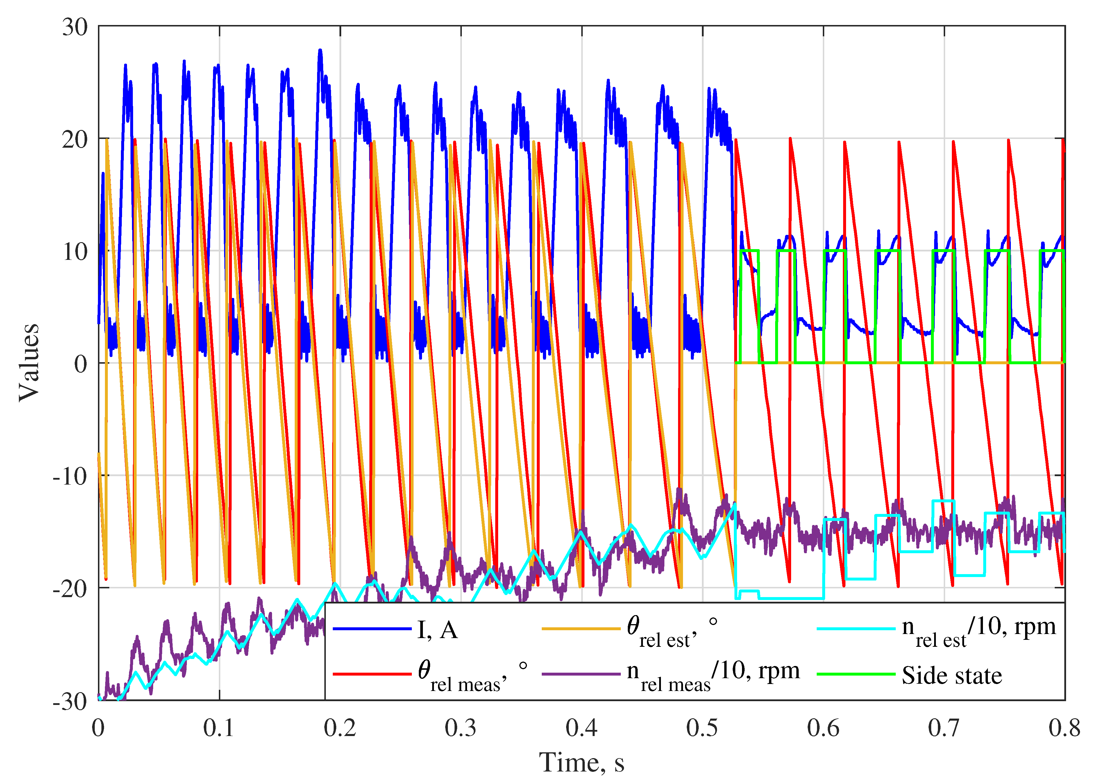
Further, the reduction of the speed difference without angular encoders have been tested (Figure 8). The shift sleeve was rotated by motor 1 at the speed of 300 rpm, and the left complementary ring was accelerated by the actuator from standstill to app. 150 rpm using the sensorless control algorithms on the left side. Comparing to the idle operation, the error in the estimated can be significant, which is caused by a higher deviation between the real and calculated values of . However, the speed difference could be successfully reduced to 120 rpm using the algorithm for higher speed differences. After that, the current was controlled using the method for lower speed differences, and the coil could be de-/magnetized at the corresponding side states to generate torque with the required sign and keep in the range suitable for shifting. It can be seen in Figure 8 that the coil state is estimated incorrectly when the algorithms are switched, which is caused by the different methods of voltage control at lower and higher speed differences (hysteresis current control with hard chopping [10] is used at higher relative speeds). However, the algorithm for lower starts to work correctly within one period of .
4. Conclusions
In this paper, two different algorithms of operation without angular encoders are developed for the novel type of electromagnetic dog clutch actuated by the integrated LRRA proposed in our previous works [1,2,3,4,5]. One algorithm is applied at lower speed differences (up to 200 rpm) while the other is used at higher speed differences. At lower relative speeds, the DC-voltage is applied to the coil and the state on the coil side (rising or falling inductance) is estimated comparing the measured current with its delayed value. The low-pass filter is used to avoid false state estimation caused by the noise in the current signal. The average value of the relative speed is estimated from the time elapsed between the state changes. The change of the relative speed sign is estimated comparing the values of estimated at the last and previous state changes. At higher speed differences, the angular position and speed of the complementary ring relative to the shift sleeve are estimated using the SMFO and the simplified model of the magnetic fluxes created by eddy currents, and the voltage is controlled using hysteresis current control with hard chopping [10]. Both algorithms are suitable for idle operation and active generation of the synchronizing torque.
Since the value of can not be estimated with the algorithm for lower speed differences, the double-sided actuator can operate there in a limited range of the synchronization current [4]. However, this problem is partially compensated by the fact that a higher torque can be generated at lower speed differences [4]. The current limitation is not required for the one-sided actuator [2,3] where the value of is not required to prevent the axial movement of the shift sleeve in rotary operation.
The possibility of sensorless operation has been verified experimentally on the double-sided dog clutch prototype installed inside the testing gearbox, and positive results have been obtained. The results of only two experiments are presented due to the limited size of the paper, but they confirm the developed theoretical ideas.
References
- Miroschnitschenko, B.; Polschak, F.; Rafetseder, D. Electromechanical clutch and method for closing and opening an electromechanical clutch and for sensorless determination of the relative angular velocity of a first and second shaft. DE102022121714A1, February 2024. [Google Scholar]
- Miroschnitschenko, B. Magnetic flux calculation in a novel linear-rotary electromagnetic actuator using 3d magnetic equivalent circuit. In Proceedings of the 2023 11th International Conference on Control, Mechatronics and Automation (ICCMA). IEEE; 2023; pp. 336–345. [Google Scholar]
- Miroschnitschenko, B.; Amrhein, W.; Poltschak, F. Design and Optimization of a Linear-Rotary Electromagnetic Actuator Based on Analytical Model of Magnetic Flux. In Proceedings of the 2024 International Symposium on Power Electronics, Electrical Drives, Automation and Motion (SPEEDAM). IEEE, 2024; pp. 1002–1009.
- Miroschnitschenko, B.; Poltschak, F.; Amrhein, W. A novel double-sided electromagnetic dog clutch with integrated synchronizer function. in publishing, https://www.preprints.org/manuscript/202505.0790/v2.
- Poltschak, F.; Rafetseder, D.; Miroschnitschenko, B. Electromagnetic direct drives for positive mechanical engagement in the automotive drivetrain. In Proceedings of the Tagungshandbuch Symposium Elektromagnetismus; 2025; pp. 93–100. [Google Scholar]
- Gongye, X.; Du, C.; Li, L.; Huang, C.; Wang, J.; Dai, Z. Research on Precise Tracking Control of Gear-Shifting Actuator for Non-Synchronizer Automatic Mechanical Transmission Based on Sleeve Trajectory Planning. Energies 2024, 17, 1092. [Google Scholar] [CrossRef]
- Miroschnitschenko, B. Sensorless Control of Linear Motion in a Linear-Rotary Reluctance Actuator Integrated into an Electromagnetic Dog Clutch. in publishing.
- Piracha, M.Z.; Grauers, A.; Hellsing, J. Time optimal control of gearbox synchronizers for minimizing noise and wear. In Proceedings of the 2020 IEEE Conference on Control Technology and Applications (CCTA). IEEE; 2020; pp. 573–580. [Google Scholar]
- Tsai, M.C.; Huang, C.C.; Huang, Z.Y. A new two-phase homopolar switched reluctance motor for electric vehicle applications. Journal of magnetism and magnetic materials 2003, 267, 173–181. [Google Scholar] [CrossRef]
- Miller, T.J.E. Electronic control of switched reluctance machines; Elsevier, 2001.
- Islam, M.S.; Husain, I.; Veillette, R.J.; Batur, C. Design and performance analysis of sliding-mode observers for sensorless operation of switched reluctance motors. IEEE Transactions on Control systems technology 2003, 11, 383–389. [Google Scholar] [CrossRef]
- Abdelmaksoud, H.; Zaky, M. Design of an adaptive flux observer for sensorless switched reluctance motors using lyapunov theory. Advances in Electrical and Computer Engineering 2020, 20, 123–130. [Google Scholar] [CrossRef]
- Ofori, E.; Husain, T.; Sozer, Y.; Husain, I. A pulse-injection-based sensorless position estimation method for a switched reluctance machine over a wide speed range. IEEE Transactions on Industry Applications 2015, 51, 3867–3876. [Google Scholar] [CrossRef]
- Zhang, X.; Wang, F.; Wu, X. Low-speed direct-driven sensorless control including zero-speed for switched reluctance motor based on dynamic inductance model. In Proceedings of the 2014 17th International Conference on Electrical Machines and Systems (ICEMS). IEEE; 2014; pp. 763–767. [Google Scholar]
Figure 1.
The LRRA integrated between two gearwheels of a gearbox represents a double-sided electromagnetic dog clutch [4].
Figure 1.
The LRRA integrated between two gearwheels of a gearbox represents a double-sided electromagnetic dog clutch [4].
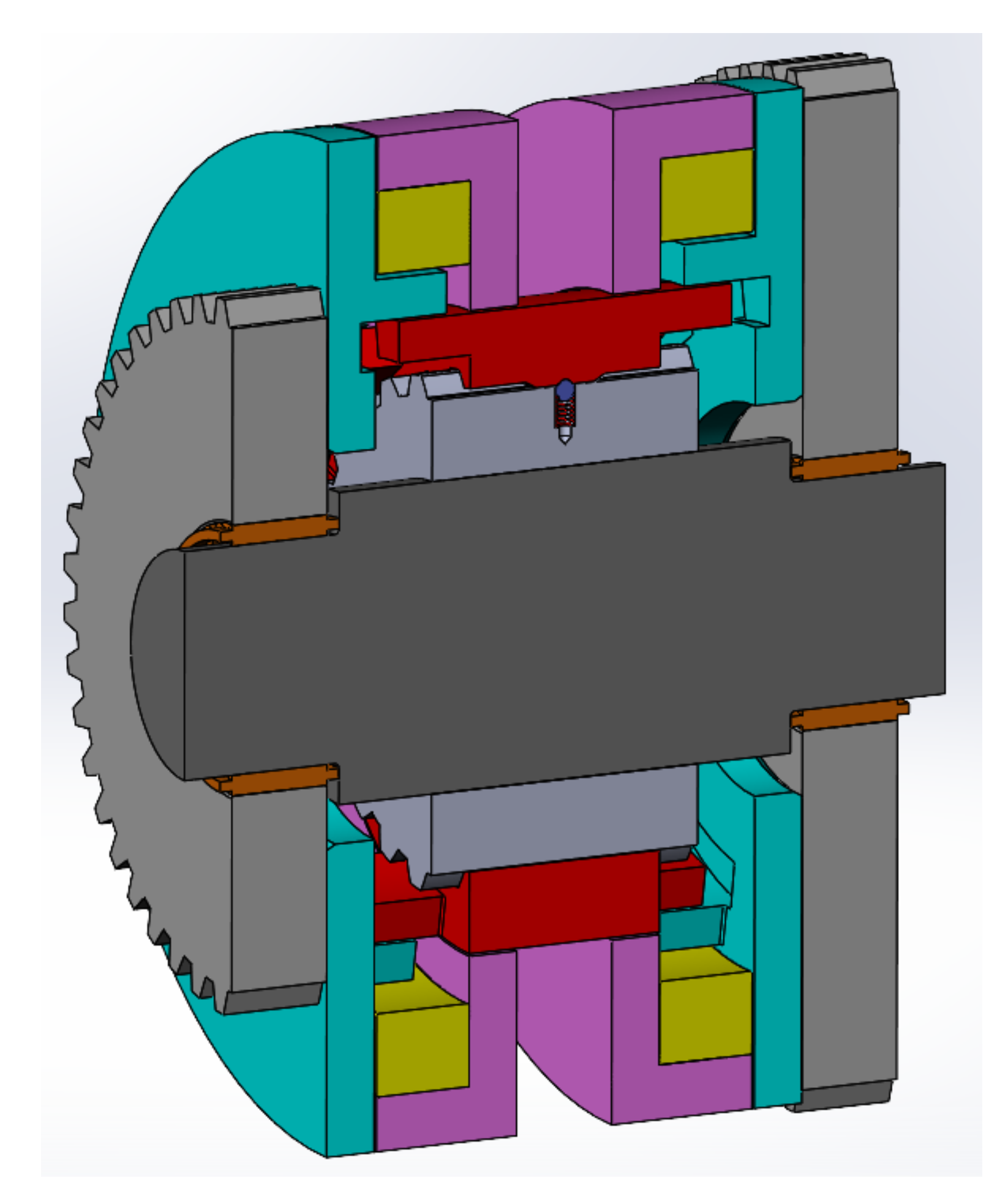
Figure 2.
Inductance characteristic of the coils in the neutral gear (the shift sleeve is at the central axial position x = 0).
Figure 2.
Inductance characteristic of the coils in the neutral gear (the shift sleeve is at the central axial position x = 0).
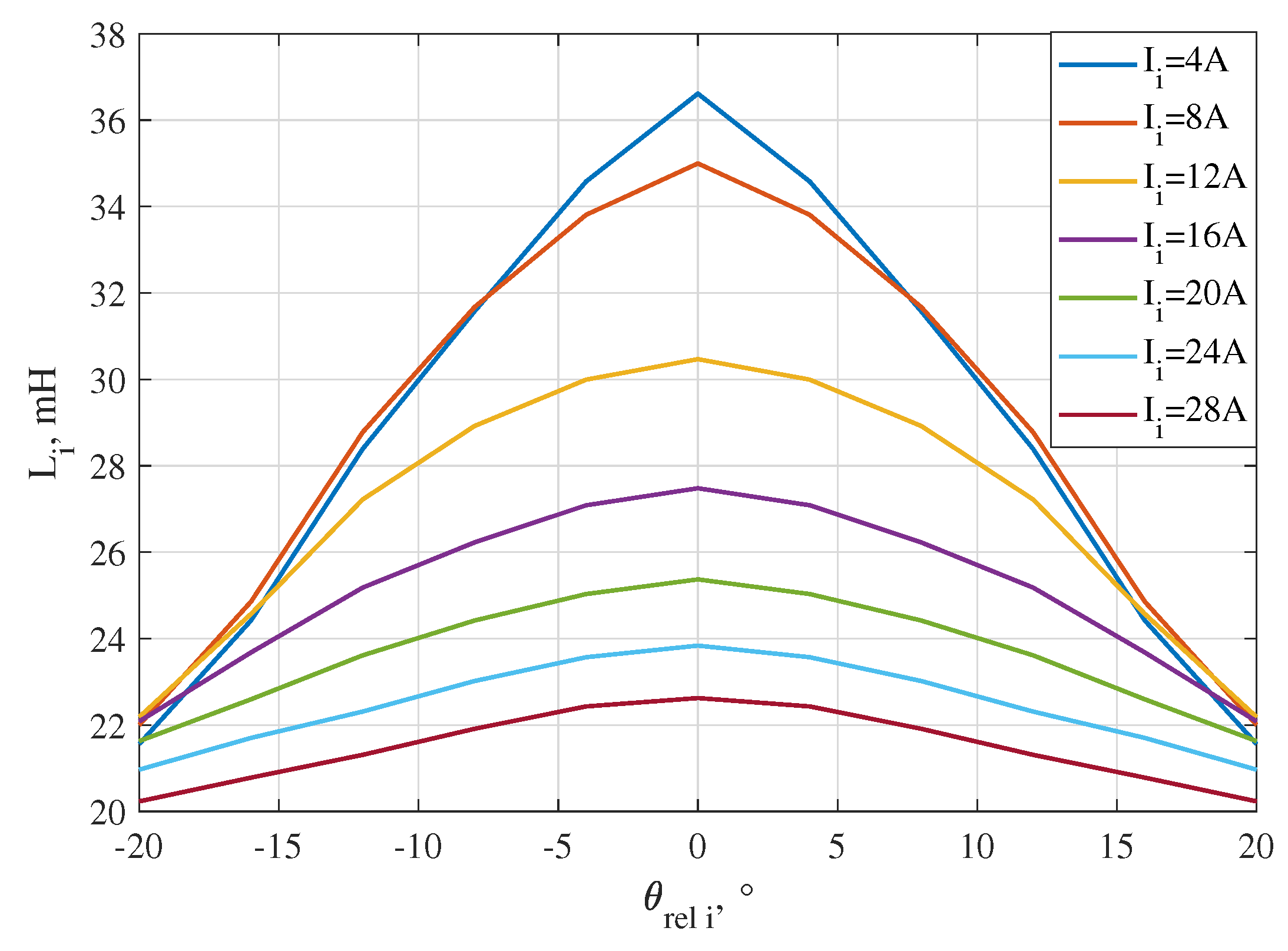
Figure 3.
Algorithm for the sensorless estimation of the side state (0 - rising inductance, 1 - falling inductance) and relative speed at lower speed differences.
Figure 3.
Algorithm for the sensorless estimation of the side state (0 - rising inductance, 1 - falling inductance) and relative speed at lower speed differences.
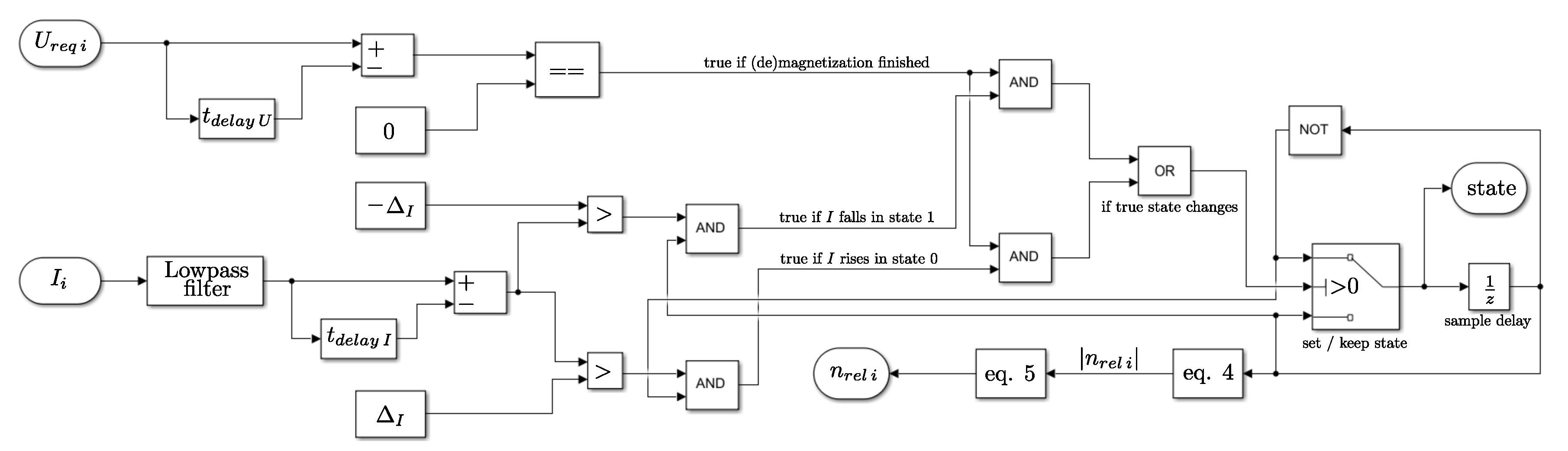
Figure 4.
Algorithm of the voltage control in sensorless operation at lower speed differences.
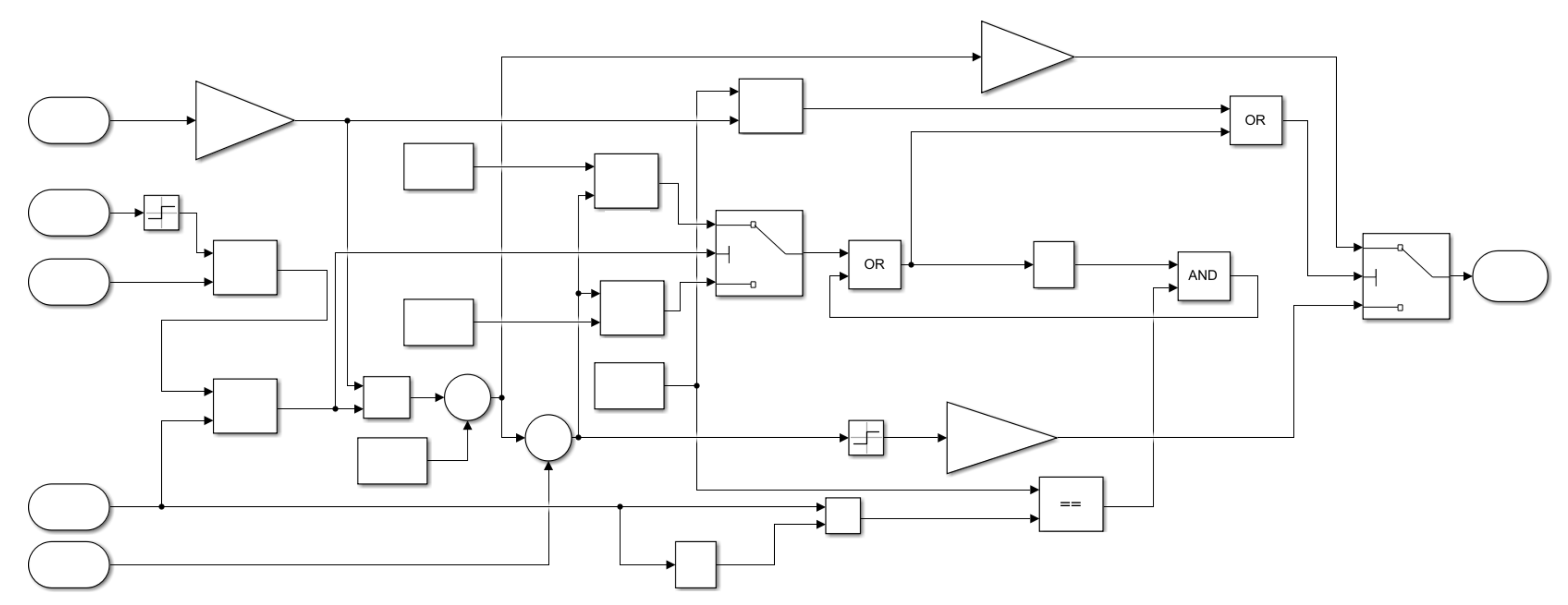
Figure 5.
Simplified model of the magnetic fluxes created by eddy currents.
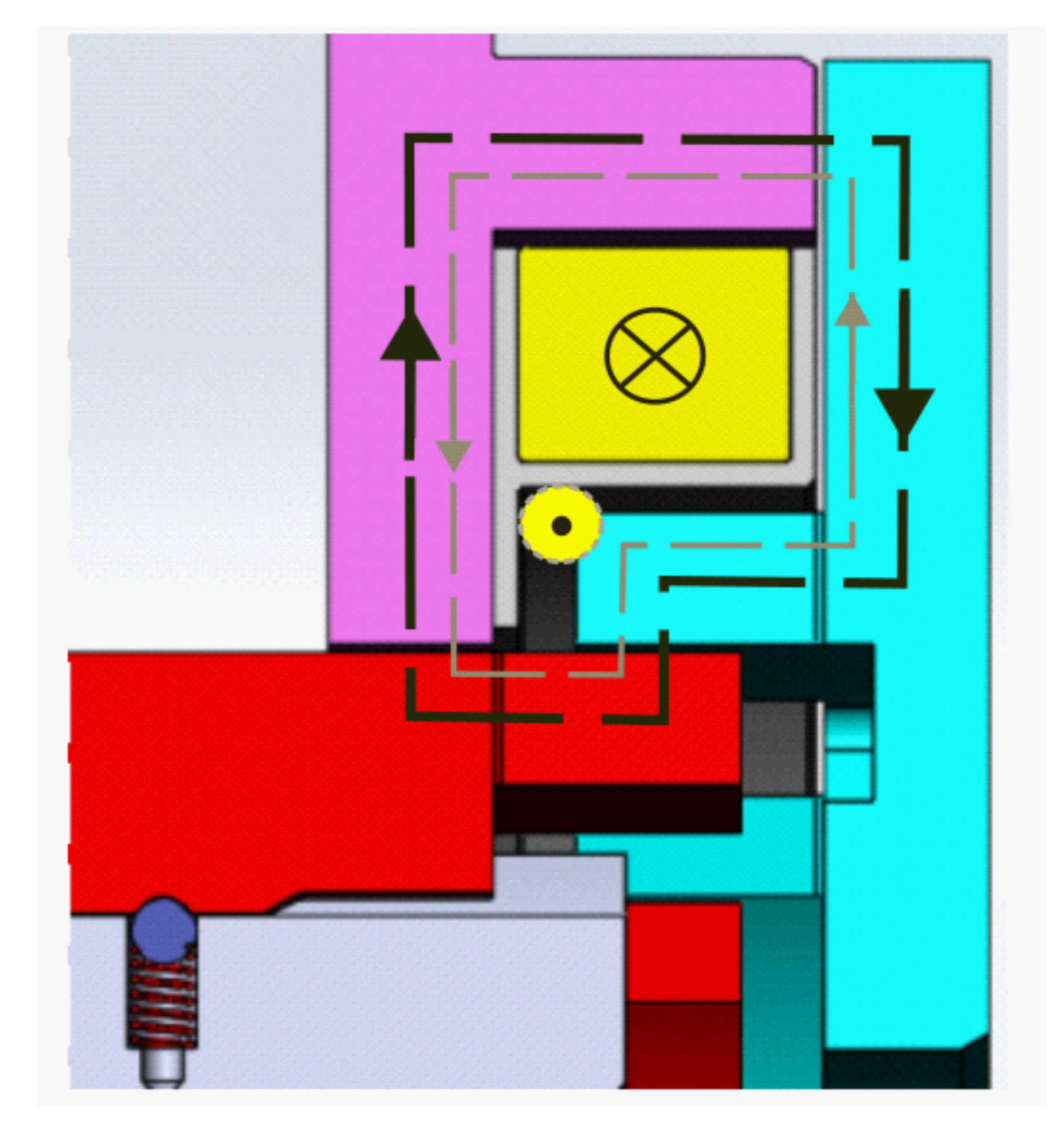
Figure 6.
Testrig with the actuator prototype installed inside the testing gearbox.
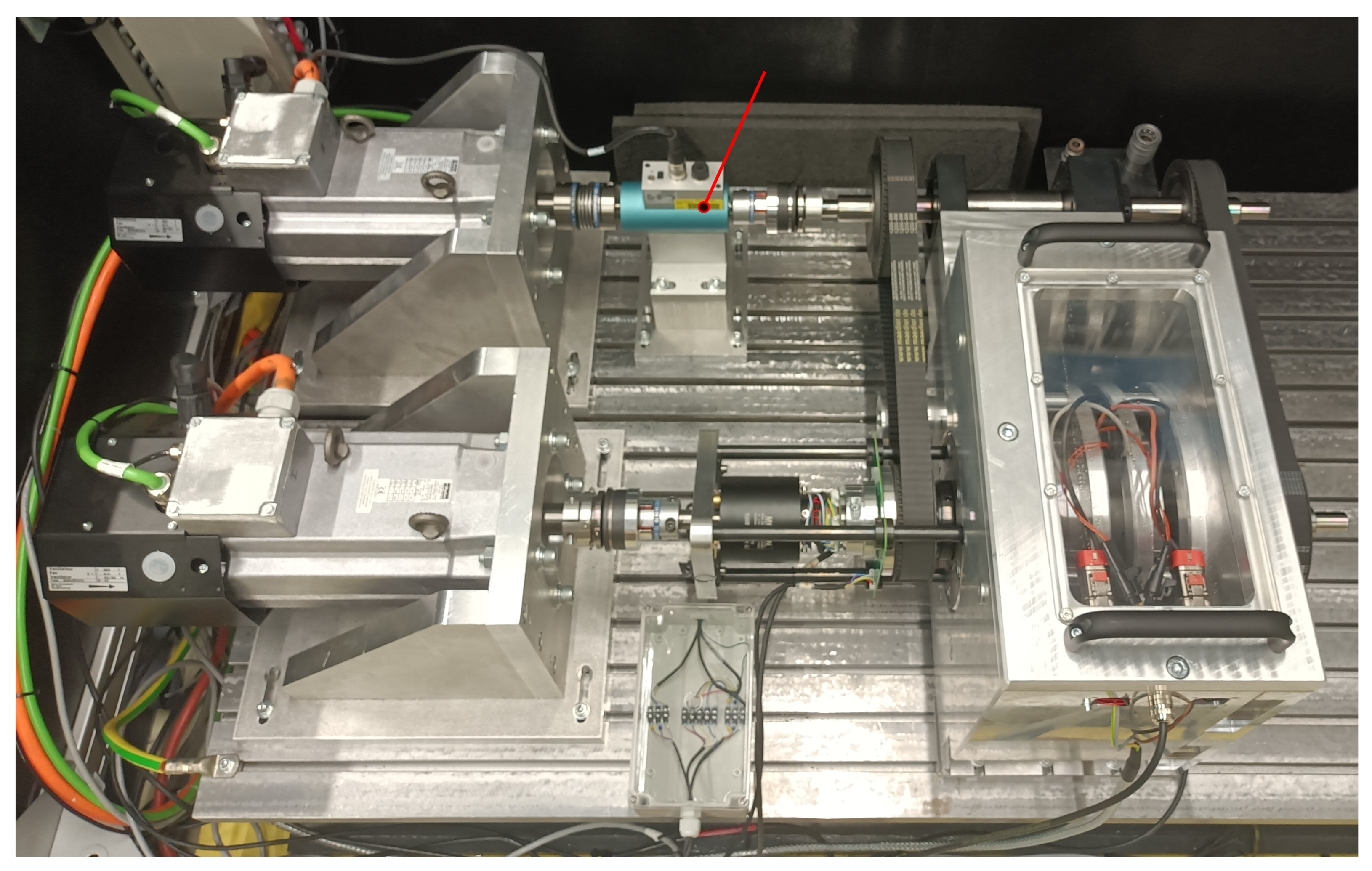
Figure 7.
Experimental results of the sensorless estimation of the relative angular position and speed in idle operation.
Figure 7.
Experimental results of the sensorless estimation of the relative angular position and speed in idle operation.
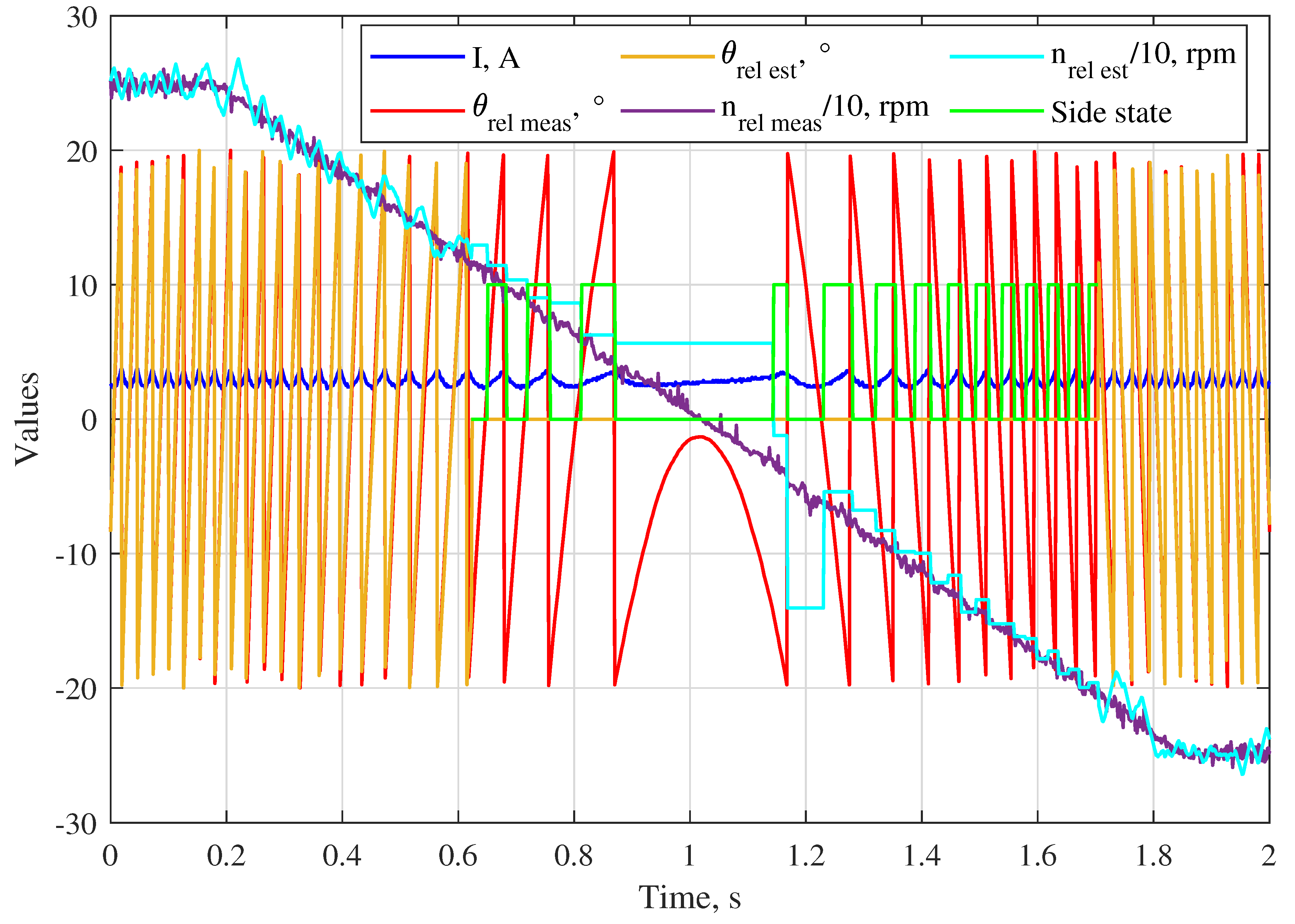
Figure 8.
Experimental results of the sensorless reduction of the relative speed
Disclaimer/Publisher’s Note: The statements, opinions and data contained in all publications are solely those of the individual author(s) and contributor(s) and not of MDPI and/or the editor(s). MDPI and/or the editor(s) disclaim responsibility for any injury to people or property resulting from any ideas, methods, instructions or products referred to in the content. |
© 2025 by the authors. Licensee MDPI, Basel, Switzerland. This article is an open access article distributed under the terms and conditions of the Creative Commons Attribution (CC BY) license (http://creativecommons.org/licenses/by/4.0/).
Copyright: This open access article is published under a Creative Commons CC BY 4.0 license, which permit the free download, distribution, and reuse, provided that the author and preprint are cited in any reuse.


