Submitted:
27 May 2025
Posted:
28 May 2025
You are already at the latest version
Abstract
This paper discusses the frequency tuning and dynamics of a novel energy harvester that converts thermal energy into mechanical vibrations of two polyvinylidene fluoride (PVDF) piezoelectric cantilevers that generate electrical energy through a shape memory alloy (SMA) filament. The vibration frequency is tuned by two ferromagnetic masses symmetrically arranged on the SMA filament and interacting with fixed NdFeB permanent magnets. The SMA filament moves transversely due to its own longitudinal temperature contractions and stretches due to a constant temperature heater. Temperature differences above the heater cause periodic changes in the length of the SMA filament, resulting in self-excited oscillations of the masses in the vertical and horizontal directions. An experimental setup was created to study the harvester by measuring the mass displacements and electrical voltages generated by the piezoelectric cantilevers. Data on the dependence of the output voltage and power on the load resistance of the consumer were obtained. The experimental results have been validated by a multiphysical dynamic model that considers the relationships between the mechanical, thermal, magnetic and electrical domains. Research shows that permanent magnets increase the frequency of bending vibrations from 8.3 Hz to 9.2 Hz. which for a heater with a constant temperature of 70 °C, increases the output power from 1.9 µW to 8.18 µW. A special feature of the proposed energy harvester design is the ability to operate at cryogenic temperatures.
Keywords:
frequency tuning
; permanent magnet
; thermal energy harvesting
; thermally self-excited vibrations
; shape memory alloys
; polyvinylidene fluoride cantilevers
1. Introduction
Energy storage from oscillating sources is a promising solution for powering low-power electronic devices [1,2,3,4]. Among the many sources of untapped ambient energy, mechanical vibration, light and thermal energy are the most widely used [5,6,7]. The high response speed, on which the efficiency of the energy provided by the mechanism depends, is a challenge for actuators based on SMA elements. The time to reach the phase transitions of these harvesters can be reduced. In other words, the response rate is limited by the heating time and especially the cooling time of the SMA element actuator. Therefore, reducing the time to reach the phase transition temperature is essential to improve the reaction rate. One of the approaches to increase the actuation speed of SMA is to reduce the dimensions. Triggering rates of up to 1.6 kHz have been reported when the thickness of the SMA element is reduced to close to 1 μm. These are several orders of magnitude higher than the speeds typically associated with SMA actuators [8]. However, the size of the SMA is not the only condition that determines the actuation speed. For some actuators, the thermal response may be slower or faster due to changes in the cooling or heating behaviour of the actuator. This means that even if actuators have similar SMA thicknesses, the actuation speeds would be different depending on the equivalent mass of the entire actuation system or the amount of supplied energy required for actuation [9,10]. Changing the chemical composition of the SMA in the actuator allows cyclic transformation of the alloy over a relatively lower temperature range. The addition of traces of Ti to the Cu-Zn-Al alloy resulted in a significant reduction in transformation phase temperatures [11].
The efficiency of energy harvesting in piezoelectric cantilever (PEC) devices depends on the magnitude of the frequency at which the mechanism oscillates [12,13]. To increase the energy harvesting efficiency, many methods have been proposed to optimise the energy harvesting by adjusting the oscillation frequency [14,15]. One solution to controlling the oscillation frequency is to use multiple piezoelectric cantilevers whose mechanical resonant frequencies are distributed across the desired oscillation frequency in such a way that, at any given frequency, at least one circuit operates close to its resonant frequency. The most general approach to the design of such a mechanism is given in [16,17]. The frequency configuration of the PEC can also be achieved by varying the magnitude of the effective mass of the beam [18] or the stiffness of the PEC [19]. The stiffness of the PEC can be varied by changing the cantilever geometry or the material properties. The solution development includes the properties of the PECs, their elements and the properties of the electrical circuit in the calculations [20]. Methods for frequency scaling [21,22], implementation of non-linear methods [23,24,25] have also been proposed.
Bouhedma at al have presented a piezoelectric vibrational energy harvester whose frequency characteristics can be altered using magnets with up to 18% change [26]. To achieve high electrical power stability, a concept of piezoelectric energy harvester that mimics the switch mechanism has been proposed. The extracted energy is increased by a collision between two magnets [27]. The dynamics of a bistable magnetic oscillator is controlled by the strength and polarization of the added magnets [28]. The extracted energy voltage reaches the highest value in nonlinear oscillations, with the output power improved by up to 600% compared to linear oscillations. The functionality of vibrational energy harvesters using magnets is reviewed, and monostable and bistable configurations introduced by magnets with different excitation levels are discussed to improve the efficiency of the harvested energy output [29]. The dynamic characteristics of broadband tristable magnetic coupling harvesters have been investigated [30]. Compared with the bistable state, the results show that this harvester easily transitions through its different states, providing high output energy over a wider frequency range. A broadband nonlinear quin-stable energy harvester is proposed [31]. To control the generation of piezoelectric energy, magnets are usually deployed in repulsive or attractive configuration [32]. This hybrid approach increases the power generation capabilities of the harvester due to the combined piezoelectric and electromagnetic operation under the same external excitation [33]. Furthermore, a new generation of devices can be developed using materials and structures based on magnetoelectric effects. Magnetoelectric effects in ferromagnetic-ferroelectric layered composites arise due to magnetostriction and piezoelectric effect during the ferroelectric phases. The important advantage of magnetic field-based methods compared to mechanical methods is their remoteness and no contact. Ferrite composites have potential applications in sensors, autonomous power sources, electrically controlled microwave devices, and others [34]. Several reviews on piezoelectric energy harvesting have been published, most of them mainly focusing on biomedical applications [35], microelectromechanical systems (MEMS) [36], nanogenerators [37], materials, and energy harvesting from various sources [38].
In previous publications, the authors of this paper have developed and investigated a self-excited thermomechanical oscillator [39] and an energy harvester[40], in which the heat of a constant-energy heater is converted into vibrations of an SMA filament. Two masses are mounted on the SMA filament, which perform vibration two perpendicular directions, longitudinal and transverse. The longitudinal vibration is due to the contraction of the SMA filament when it is close to the heater. These contractions shorten the filament, and this causes it to move away from the heater and subsequently cool with elongation due to the inertial forces of the masses. The transverse vibrations are due to the relative movement of the filament from the SMA in the vertical direction and are caused by inertial forces and the weight of the masses in addition to the contractions. The variation of the Young’s modulus due to the phase changes of the SMA cause another oscillation of higher frequency which is summed with the longitudinal oscillations. The energy harvester [40]implemented on this principle transforms the resulting oscillations, through piezoelectric cantilevers mounted at the ends of the filament. Studies have shown that the vibrations have a pseudo-stochastic character due to the hysteresis of the relative martensitic fraction.
The aim of this paper is to investigate the possibilities of increasing the generated power of the above-described self-excited thermal energy harvester by tuning the natural frequency of the vibrating system using permanent magnets.
2. Design Concept of Energy Harvester and Natural Frequency Tuning System
The thermoelectric energy harvester consists of an SMA filament that is fixed between two fixed supports O and C, symmetrically arranged relative to a fixed heater. Two identical spheres are fixedly mounted on the filament near the heater, on which magnetic forces due to symmetrically placed NdFeB magnets (M1 and M2) act. Two piezoelectric cantilevers and are positioned at the fixed ends of the SMA filament, which are mounted, using a heat-resistant foil, to follow the bending of the filament. The whole structure is symmetric about the y ordinate of the fixed coordinate system O1xy (Figure 1). The filament material is a shape memory alloy of nitinol known by the trademark Flexinol® [41]. For the piezoelectric cantilevers, two vibration sensors type DT1-052K [42] were used, which are constructed of a thin PVDF piezoelectric film metallized with silver on both sides representing flexible electrodes covered with plastic protective layers and galvanically connected with solder terminals.
The principle of operation of the energy harvester, as already mentioned above, is based on temperature changes above the heater, which are high near its surface and cause contractions of the SMA filament and its simultaneous moving away from the warm zone. Once in the lower temperature zone, the SMA filament softens and stretches under the inertial forces of the masses, bringing it closer to the heater and the action zone of the magnets. These actions are repeated continuously, resulting in a cyclic vibration process of the SMA filament and mass system. Near the supports, the vibrational bends of the SMA filament are transmitted to the piezoelectric cantilevers and they generate electrical energy (see Video from Supplementary Material).
3. Composing the Dynamical Model by Combining the Interactions of the Different Physical Domains
The distance between the two supports O and C can be adjusted, which creates possibilities to mount the SMA filament with pre-tension or pre-sag. The geometric parameter designations are in accordance with Figure 1 and the approach for determining the elastic and temperature deformations of SMA filament and PVDF cantilevers is similar to the approach described in [40].
3.1. Determination of Elsatic and Temperature Parameters of the SMA Filament and Bending of the Piezoelectric Cantilevers
Since half of the distance between supports O and C is denoted by l, one can express the pre-strain Δls0 of this parameter
where ls is for half the length of the SMA filament before tensioning.
A relative length is introduced as
where , are the lengths of the filament sections when the ferromagnetic spheres are on the line OC.
Considering the symmetry and uniformly distributed deformations along the entire length of the filament, then for the end sections OA0 and B0C for the pre-strains and , follows
In this case for the middle section A0B0 its deformation can be written
Due to the specific symmetrical design shown in Figure 1, it can be assumed that in the middle section AB the filament moves parallel to the horizontal surface of the heater and therefore heats uniformly along its entire length. Since the end sections are relatively far from the heater they are assumed not to heat up and their temperature is low i.e., they are cold sections with a temperature equal to that of the room. The deformation of the cold (or end) sections due to the displacement of the masses and the initial tension for the symmetrical motion variant has the form
and
where , , , , , , are the coordinates of the points O, A, B and C.
Under the same conditions for the deformation of the middle section can be written
Since the end sections of the SMA filament are always cold and it is assumed that the room temperature is always below the final martensitic temperature Mf of NiTi, the stiffness of these sections can be expressed by
Where is the NiTi Young’s modulus in the martensitic state, and A is the cross-sectional area of the SMA filament.
For the stiffness of the middle section, it can be written
but since this section is subjected to varying temperatures that cause all phase transformations in NiTi the Young’s modulusalso transforms depending on the current phase. According to the model discussed in [43], this module can be represented by the piecewise function
where , , , and are Young’s modulus of the fully twined, partially twined, detwinned martensite and austenite respectively; is the yield strain of the twined martensite; is the minimum strain of the detwinned martensite, and
is the strain of the middle section.
The relative martensite fraction is expressed in the form
where is the current temperature of the NiTi, the temperature depends on whether the thermal process is heating or cooling and is obtained by the relation
The unit of coefficient is temperature, calculated by the expression
where As, Af, Ms, and Mf are the start and finish temperatures for austenite and martensite phases of NiTi. The limiting values of the coefficients, and , have been established experimentally [44].
The method for hysteresis modeling is described in detail in [43]. It is based on the analysis of temperature fluctuation point at which gradient change of a transient temperature occurs.
If is in the transient periods with both martensite and austenite fraction in the NiTi exist. Let denote the derivatives of the transient temperature versus time before fluctuation point with and after fluctuation point with .
If the condition
is satisfied, then the so-called scale factor is
and
If at the fluctuation temperature , the NiTi temperature changes from cooling to warming, i.e.,
The scale factor is calculated by
and
Similarly, sub-minor hystereses are described, which occur in the case that already a minor hysteresis appears, and a sub-minor fluctuation temperature occurs in it during a transient. For these cases, analogous approaches described in [43]are used.
To simplify the general formulation of the problem, it is assumed that the temperature field above the heater in which the NiTi filament moves is stationary. In addition, the simplifying assumption that the NiTi filament itself obtains a potential temperature from this field by dependence
where coordinates are determined experimentally [45] and they depend on the heater position, is the maximum temperature received by the filament from the heater and is a conditional length, andis the temperature of the room.
Considering (21) and the hysteresis theory of the relative martensitic fraction (12)- (20), it is seen that the Young’s modulus for the middle section is a potential function of the coordinates of the ferromagnetic masses and the temperature of the SMA filament, which is here also assumed to be a potential function. These properties facilitate the application of Lagrange equations of the second kind to the solution of the dynamics problem.
The bending of the piezoelectric beams due to the movement of the SMA filament is assumed to be as in [40] where, since the bent shape for the left cantilever is assumed to be a parabola of the form
and for the right cantilever the bent shape is described with the parabola
where is the length of the piezoelectric cantilever, and are factors that are determined assuming that the angle of inclination at the end of the cantilevers coincides with that of the SMA filament at the same point (Figure 2).
In accordance with the assumptions on the shape of the bending, the factors are found
3.2. Determination of Magnetic Forces and Their Potential Energy
It is assumed that the magnetic force between a spherical ferromagnetic mass and a permanent magnet as depicted in Figure 3(a) is approximated by the function
where is called the imaginary magnetic mass, and is the imaginary initial gap and is the distance between the surface of the magnet and the center of the sphere. The same force function was determined in [46] based on numerical approximations and experiments.
The force function (26), also called the static magnetic force characteristic, has the graphical interpretation shown in Figure 3(b). The magnetic force at a conditional zero gap (it is called conditional because the distance between the sphere and the magnet can practically never be zero because of the roughness and deviations from the shapes of the two surfaces) at =0 is the initial magnetic force
from where the unit of the imaginary magnetic mass [Nm2] is evident.
The schematic experimental setup shown in Figure 4 was used to determine the force exerted by the M1 magnet on one of the spheres and its potential energy. A current position of the ferromagnetic mass at point A, located at position . The influence of the displacement of the masses along the axis on the magnetic forces is neglected.
Taking into account that
according to (26) the left magnet M1 will exert the force
The right magnet M2 will exert the same force because the coordinates of the two ferromagnetic masses are equal.
The potential energies of the two magnet forces are determined after integration
3.3. Derivation of the Lagrange Equations of the Second Kind
In the energy harvester investigated here, the two ferromagnetic masses move along the and axes and, in addition, the two piezoelectric cantilever beams generate two different electric charges of the left cantilever and of the right cantilever. This means that the generalized coordinates are six in total. Four of them the coordinates, , , and are mechanical and the two charges and are electrical.
Since the energy harvester is assumed to be in its symmetrical configuration, the following notations can be introduced , , , , , and. Note that symmetry reduces the generalised coordinates from six to three , and . The symmetry also allows the following notations to be introduced , , , , , , and .
The kinetic energy of the symmetric mechanical system is obtained in the form
where the dot denotes the derivatives of the coordinates with respect to time, and is the mass of a ferromagnetic sphere.
The potential energy (except the piezoelectric one) consists of the mechanical potential energy and the magnetic potential energy, therefore it is expressed by
where
and
The piezoelectric energy , according to [47], is derived in the form
where
is the lengthen of the piezoelectric cantilever
is equivalent capacitance of the piezoelectric transducer, , are piezoelectric constant of PVDF and the dielectric permittivity respectively, is the compliance of the piezoelectric cantilever under constant electric field, is the electromechanical coupling coefficient of PVDF, , , and are the second moment of area width, and the thickness of the PVDF cantilever respectively.
Based on the above results, the Lagrangian of the magnetoelectromechanical system is written in the form
The system of three coupled equations describing the behavior of the multiphysics energy harvester is derived according to the Lagrange equations, which has the form
in which the generalized coordinates are , and, and the generalized forces have the form
Where , are the viscous resistance coefficients along the axis and , respectively, is the ground acceleration, is the load resistance in the circuit of the piezoelectric cantilevers when connected in parallel.
Applying the equations (40) to (39), the following system is derived:
where
and
The Young’s modulus derivative for the middle section of SMA filament here is calculated according to the relation
where the derivative of the relative martensite fraction considering (21) is
From the second equation of the system (42), it can be concluded that the magnetic system has a contribution which is expressed by a potential force of the form
This force presented in Maclaurin’s series leads to
The factor in front of indicates that the magnetic system will increase the natural mechanical frequency of vibration along the coordinate.
The system of ordinary differential equations (42) was solved numerically using the data in Table 1.
4. Experimental Studies on the Influence of Magnetic Tuning
The experimental investigations of the influence of the magnetic system on the natural frequency tuning were carried out using a dedicated experimental setup. The schematic concept of this experimental setup is shown in Figure 5(a). Figure 5 (b) shows a top view of the whole experimental setup. Figure 5 (c) is a close-up view of the left side of the energy harvester with the PVDF cantilever 2, horizontal position sensor 3, ferromagnetic mass 4, heater 5 and magnets 10. Figure 5(d) is a picture of the right side of the energy harvester showing the sphere 4, heater 5, vertical position sensor 6, SMA filament 7, right support 8 and magnets 10.
In the experimental setup to the energy harvester comprising the heater 5 located in the middle strand of the CMA 7, the ferromagnetic spheres 4 on which the NdFeB magnets 10 act directly. Sensors are added to determine the horizontal 3 and vertical 6 displacement of the masses. These sensors are of the type of APO-075-002-000 from TT Elastronics Ltd. UK. Variable load resistors 1 are connected in parallel to the outputs of the two piezoelectric beams 2, the resistance of which is adjusted by an ohmmeter 9. The voltages from the piezoelectric beams and the two position sensors are fed into a Data Acquisition System DAQ USB - 6003 from National Instruments, then processed by a laptop using a LabVIEW 11 program to save to an Excel file.
In order to investigate the influence of magnets on the output voltage, two types of experiments were conducted. In the first, the results of the displacement along the two axes and the generated output voltage with the magnets removed were recorded. In the second type of experiments, the same signals were recorded but in the presence of magnets. In these experiments, the location and number of magnets was chosen to obtain the maximum output voltage.
A comparison between the output voltages of the energy harvester without and with permanent magnets is shown in Figure 6. The plot of the resulting voltage without magnets is shown in Figure 6(a), and the same output voltage but with magnets added is given in Figure 6(b). It can be seen that the magnet increases the vibration frequency of the piezoelectric cantilevers and furthermore increases the magnitude of the generated output voltage.
From the graphs, it is found that the magnets resulted in an increase in the output peak-to-peak voltage from 6.12 to 14,14 V, which is about 130% increase in output voltage of the energy harvester with magnets. The magnets increased the output voltage frequency from 8,3 Hz to 9,2 Hz, which in this case is about an 11% increase in frequency.
Maximum power P=1.9 µW for energy harvester without magnet is obtained at load resistance of RL=7 MOhms. For energy harvester with magnets the obtained maximum power P=8.18 µW at a load resistance RL = 5 MOhms. This result shows that the magnets contributed to increasing the output optimum power by 330%.
5. Comparison of Theoretical and Experimental Data to Validate the Dynamic Model
The dynamical model consisting of the system of differential equations (42) differs from the model solutions in [40] in the added potential magnetic energy. For the solution of the system the same approach based on implicit fifth order Euler method and the same initial conditions according to Table 1 was used.
Figure 8 (a), (b) and (c) show the experimental results for the output voltage, the displacement of the spheres along the y-axis and x-axis, respectively. For comparison, Figure 8 (d), (e) and (f) show the results obtained from the solution of system (42).
The numerical simulation results show a reasonably good confirmation of the experimental data. In analogous studies in [40], it was found that due to the multiple hystereses and the variable nature of the SMA filament heating, the vibrations have a pseudo-stochastic character that affects both the amplitudes and the frequencies and phases. The variation of the temperature modulus with the Young’s modulus leads to a change in the frequencies of three types of oscillations one thermal along the x-axis and two mechanicals along both axes x, and y. The x-axis displacements sum, which is the cause of the modulated vibrations along this axis.
The system of ordinary differential equations [42] is highly non-linear due to discontinuities on the right-hand sides of the functions caused by hysteresis. This makes them stiff and difficult to solve numerically. Attempts to use standard methods such as Runge-Kutta-Fehlberg 7(8) were unsuccessful, and a solution was only obtained by controlling the time step and number of iterations using the implicit Euler method [49] (see the Maple code form Supplementary Material).
6. Conclusions
In a newly developed thermal energy harvester with an SMA filament, a system of permanent magnets was added to influence the displacement of ferromagnetic masses attached to the SMA filaments. Since the heat source is at a constant temperature, thermal energy conversion is achieved by self-excited vibrations of the SMA filament and subsequent mechanoelectrical conversion by piezoelectric PVDF cantilevers. It has been shown experimentally and theoretically that permanent magnets increase the natural vibration frequency of the system SMA filament and ferromagnetic masses.
As a result of the action of the permanent magnets, the output voltage power of the thermal energy harvester increased from 1.9 µW to 8.18 µW, which is an increase of about 330%. An increase in the output peak-to-peak voltage from 6.12 V to 14.14 V was also observed.
The experimental setup developed is capable of measuring vibration processes in real time, where no integration is required to determine the displacement. This is because the signal for the displacement along both axes is obtained from a non-contact inductive sensor which only needs to be calibrated. If an inertial sensor such as an accelerometer were used, the double integration required to calculate the displacement would introduce large errors.
An interesting feature of the thermal energy harvester under consideration is that it can operate at cryogenic temperatures due to the wide temperature range over which the phase transformation of NiTi can be varied.
Supplementary Materials
The following supporting information can be downloaded at the website of this paper posted on Preprints.org. Video S1: Magnetic Tuning of a Thermal Energy Harvester, File S2: Maple code of ODE system solution.
Author Contributions
Conceptualization, T.T., Т.G., G.T. and I.Y.; methodology, T.T. and Т.G.; software, T.T. and I.Y.; validation, I.Y.; formal analysis, G.T.; investigation, I.Y. and T.T.; resources, Т.G.; data curation, Т.G.; writing—original draft preparation, T.T. and I.Y.; writing—review and editing, G.T. and Т.G.; visualization, T.T.; supervision, T.T.; project administration, G.T.; funding acquisition, G.T. All authors have read and agreed to the published version of the manuscript.
Funding
This research was funded by the European Union-NextGenerationEU through the National Recovery and Resilience Plan of the Republic of Bulgaria, project № BG-RRP-2.004-0005.
Data Availability Statement
The data are contained within the article.
Conflicts of Interest
The authors declare no conflicts of interest.
References
- Tang, L.; Yang, Y.; Soh, C.K. Toward Broadband Vibration-Based Energy Harvesting. J Intell Mater Syst Struct 2010, 21, 1867–1897. [CrossRef]
- Yang, Y.; Tang, L.; Li, H. Vibration Energy Harvesting Using Macro-Fiber Composites. Smart Mater Struct 2009, 18, 115025. [CrossRef]
- Arnold, D.P. Review of Microscale Magnetic Power Generation. IEEE Trans Magn 2007, 43, 3940–3951. [CrossRef]
- Erturk, A.; Inman, D.J. Issues in Mathematical Modeling of Piezoelectric Energy Harvesters. Smart Mater Struct 2008, 17, 065016. [CrossRef]
- Adu-Manu, K.S.; Adam, N.; Tapparello, C.; Ayatollahi, H.; Heinzelman, W. Energy-Harvesting Wireless Sensor Networks (EH-WSNs). ACM Trans Sens Netw 2018, 14, 1–50. [CrossRef]
- Shaikh, F.K.; Zeadally, S. Energy Harvesting in Wireless Sensor Networks: A Comprehensive Review. Renewable and Sustainable Energy Reviews 2016, 55, 1041–1054. [CrossRef]
- Wei, C.; Jing, X. A Comprehensive Review on Vibration Energy Harvesting: Modelling and Realization. Renewable and Sustainable Energy Reviews 2017, 74, 1–18. [CrossRef]
- Lee, H.; Kim, M.; Lee, G.; Kim, C.; Ahn, S. Shape Memory Alloy (SMA)-Based Microscale Actuators with 60% Deformation Rate and 1.6 KHz Actuation Speed. Small 2018, 14. [CrossRef]
- AbuZaiter, A.; Nafea, M.; Mohamed Ali, M.S. Development of a Shape-Memory-Alloy Micromanipulator Based on Integrated Bimorph Microactuators. Mechatronics 2016, 38, 16–28. [CrossRef]
- Wang, Z.; Hang, G.; Wang, Y.; Li, J.; Du, W. Embedded SMA Wire Actuated Biomimetic Fin: A Module for Biomimetic Underwater Propulsion. Smart Mater Struct 2008, 17, 025039. [CrossRef]
- Kuo, T.Y.; Lin, H.S.; Lee, H.T. The Relationship between of Fracture Behaviors and Thermomechanical Effects of Alloy AA2024 of T3 and T81 Temper Designations Using the Center Crack Tensile Test. Materials Science and Engineering: A 2005, 394, 28–35. [CrossRef]
- Li, T.; Chen, Y.H.; Ma, J. Frequency Dependence of Piezoelectric Vibration Velocity. Sens Actuators A Phys 2007, 138, 404–410. [CrossRef]
- Qiu, Y.; Sun, S.; Xu, C.; Wang, Y.; Tian, Y.; Liu, A.; Hou, X.; Chai, H.; Zhang, Z.; Wu, H. The Frequency-Response Behaviour of Flexible Piezoelectric Devices for Detecting the Magnitude and Loading Rate of Stimuli. J Mater Chem C Mater 2021, 9, 584–594. [CrossRef]
- Dechant, E.; Fedulov, F.; Fetisov, L.; Shamonin, M. Bandwidth Widening of Piezoelectric Cantilever Beam Arrays by Mass-Tip Tuning for Low-Frequency Vibration Energy Harvesting. Applied Sciences 2017, 7, 1324. [CrossRef]
- Shi, G.; Yang, Y.; Chen, J.; Peng, Y.; Xia, H.; Xia, Y. A Broadband Piezoelectric Energy Harvester with Movable Mass for Frequency Active Self-Tuning. Smart Mater Struct 2020, 29, 055023. [CrossRef]
- Shahruz, S.M. Design of Mechanical Band-Pass Filters for Energy Scavenging. J Sound Vib 2006, 292, 987–998. [CrossRef]
- Shahruz, S.M. Limits of Performance of Mechanical Band-Pass Filters Used in Energy Scavenging. J Sound Vib 2006, 293, 449–461. [CrossRef]
- Cui, Y.; Mo, S.; Hu, W.; Lu, D. Effective Beam Mass of Diametrically Driven Self-Accelerating Beams in Photonic Lattices. Phys Lett A 2023, 489, 129159. [CrossRef]
- Staszak, N.; Gajewski, T.; Garbowski, T. Effective Stiffness of Thin-Walled Beams with Local Imperfections. Materials 2022, 15, 7665. [CrossRef]
- Huan Xue; Yuantai Hu; Qing-ming Wang Broadband Piezoelectric Energy Harvesting Devices Using Multiple Bimorphs with Different Operating Frequencies. IEEE Trans Ultrason Ferroelectr Freq Control 2008, 55, 2104–2108. [CrossRef]
- Chen, S.; Ma, L.; Chen, T.; Liu, H.; Sun, L.; Wang, J. Modeling and Verification of a Piezoelectric Frequency-up-Conversion Energy Harvesting System. Microsystem Technologies 2017, 23, 2459–2466. [CrossRef]
- Žižys, D.; Gaidys, R.; Ostaševičius, V.; Narijauskaitė, B. Vibro-Shock Dynamics Analysis of a Tandem Low Frequency Resonator—High Frequency Piezoelectric Energy Harvester. Sensors 2017, 17, 970. [CrossRef]
- Hao Jiang; Kiziroglou, M.E.; Yates, D.C.; Yeatman, E.M. A Motion-Powered Piezoelectric Pulse Generator for Wireless Sensing via FM Transmission. IEEE Internet Things J 2015, 2, 5–13. [CrossRef]
- Ibrahima, D.Sh.; Muthalif, A.G.A.; Saleh, T. A Piezoelectric Based Energy Harvester with Magnetic Interactions: Modelling and Simulation. Adv Mat Res 2015, 1115, 549–554. [CrossRef]
- Upadrashta, D.; Yang, Y.; Tang, L. Material Strength Consideration in the Design Optimization of Nonlinear Energy Harvester. J Intell Mater Syst Struct 2015, 26, 1980–1994. [CrossRef]
- Bouhedma, S.; Zheng, Y.; Lange, F.; Hohlfeld, D. Magnetic Frequency Tuning of a Multimodal Vibration Energy Harvester. Sensors 2019, 19, 1149. [CrossRef]
- Yang, C.-L.; Chen, K.-W.; Chen, C.-D. Model and Characterization of a Press-Button-Type Piezoelectric Energy Harvester. IEEE/ASME Transactions on Mechatronics 2019, 24, 132–143. [CrossRef]
- Cottone, F.; Vocca, H.; Gammaitoni, L. Nonlinear Energy Harvesting. Phys Rev Lett 2009, 102, 080601. [CrossRef]
- Tang, L.; Yang, Y.; Soh, C.-K. Improving Functionality of Vibration Energy Harvesters Using Magnets. J Intell Mater Syst Struct 2012, 23, 1433–1449. [CrossRef]
- Zhou, S.; Cao, J.; Inman, D.J.; Lin, J.; Liu, S.; Wang, Z. Broadband Tristable Energy Harvester: Modeling and Experiment Verification. Appl Energy 2014, 133, 33–39. [CrossRef]
- Wang, C.; Zhang, Q.; Wang, W. Wideband Quin-Stable Energy Harvesting via Combined Nonlinearity. AIP Adv 2017, 7. [CrossRef]
- Bouzelata, Y.; Kurt, E.; Uzun, Y.; Chenni, R. Mitigation of High Harmonicity and Design of a Battery Charger for a New Piezoelectric Wind Energy Harvester. Sens Actuators A Phys 2018, 273, 72–83. [CrossRef]
- Iqbal, M.; Khan, F.U. Hybrid Vibration and Wind Energy Harvesting Using Combined Piezoelectric and Electromagnetic Conversion for Bridge Health Monitoring Applications. Energy Convers Manag 2018, 172, 611–618. [CrossRef]
- Gupta, R.; Tomar, M.; Kumar, A.; Gupta, V. Performance of Magnetoelectric PZT/Ni Multiferroic System for Energy Harvesting Application. Smart Mater Struct 2017, 26, 035002. [CrossRef]
- Dąbrowska, A.; Greszta, A. Analysis of the Possibility of Using Energy Harvesters to Power Wearable Electronics in Clothing. Advances in Materials Science and Engineering 2019, 2019, 1–13. [CrossRef]
- Tian, W.; Ling, Z.; Yu, W.; Shi, J. A Review of MEMS Scale Piezoelectric Energy Harvester. Applied Sciences 2018, 8, 645. [CrossRef]
- Park, J.Y.; Salauddin, M.; Rasel, M.S. Nanogenerator for Scavenging Low Frequency Vibrations. Journal of Micromechanics and Microengineering 2019, 29, 053001. [CrossRef]
- Kou, J.; Liu, Y.; Zhu, Y.; Zhai, J. Progress in Piezotronics of Transition-Metal Dichalcogenides. J Phys D Appl Phys 2018, 51, 493002. [CrossRef]
- Yotov, I.; Todorov, G.; Todorov, T. Study of Self-Excited Thermomechanical Oscillator with Shape Memory Alloys. Actuators 2024, 13, 182. [CrossRef]
- Yotov, I.; Todorov, G.; Gieva, E.; Todorov, T. Dynamics of a Self-Excited Vibrating Thermal Energy Harvester with Shape Memory Alloys and PVDF Cantilevers. Actuators 2024, 14, 8. [CrossRef]
- Dynalloy Inc. Technical Characteristics of Flexinol Actuator Wire Available online: https://www.dynalloy.com/pdfs/TCF1140.pdf (accessed on 14 November 2024).
- TE Connectivity Piezo Film Sensor Without Leads Available online: https://www.te.com/en/product-11032265-00.html (accessed on 14 November 2024).
- Mitrev, R.; Todorov, T.; Fursov, A.; Ganev, B. Theoretical and Experimental Study of a Thermo-Mechanical Model of a Shape Memory Alloy Actuator Considering Minor Hystereses. Crystals (Basel) 2021, 11, 1120. [CrossRef]
- Mitrev, R.; Todorov, T.S. A Case Study of Experimental Evaluation of the Properties of Shape Memory Alloy Wires.; 2022; p. 060010.
- Yotov, I.; Todorov, G.; Todorov, T. Study of Self-Excited Thermomechanical Oscillator with Shape Memory Alloys. Actuators 2024, 13, 182. [CrossRef]
- Todorov, T.S.; Mitrev, R.P.; Tudjarov, B.N.; Nikolov, R.F. Qualitative Analysis of Oscillating Magnetomechanical System. IOP Conf Ser Mater Sci Eng 2019, 618, 012054. [CrossRef]
- Preumont, А. Mechatronics: Dynamics of Electromechanical and Piezoelectric Systems; Springer Science & Business Media, 2006;
- Sessler, G.M. Piezoelectricity in Polyvinylidenefluoride. J Acoust Soc Am 1981, 70, 1596–1608. [CrossRef]
- Butcher, J.C. Numerical Methods for Ordinary Differential Equations; John Wiley & Sons: New York, 2003;
Figure 1.
Scheme of the thermoelectric energy harvester.
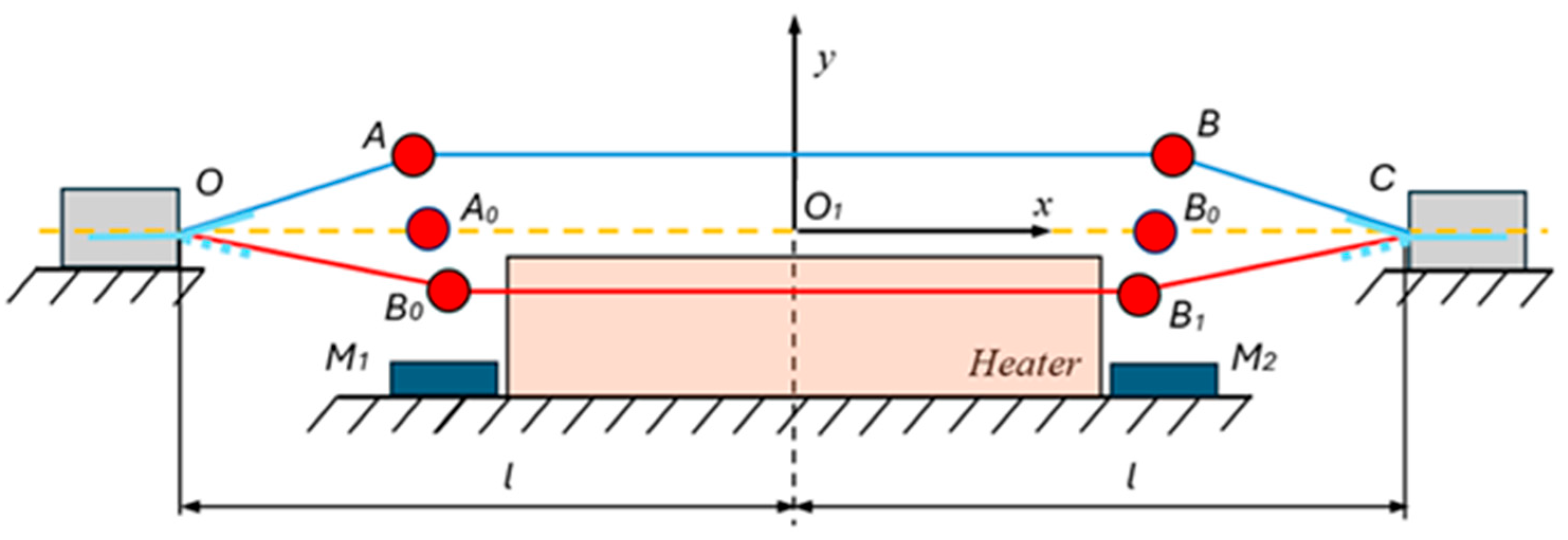
Figure 2.
Determination of the bending of piezoelectric cantilevers.
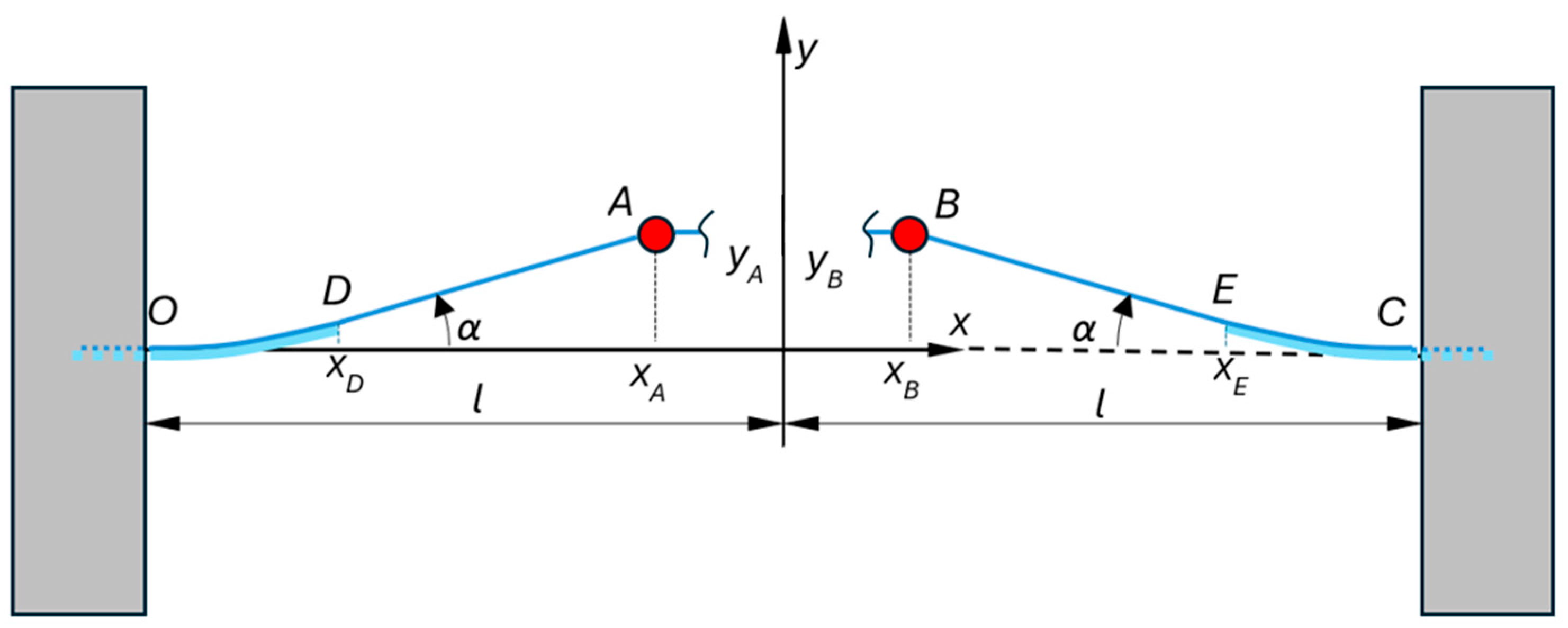
Figure 3.
Magnetic force between a permanent magnet and a spherical ferromagnetic mass: (a) problem statement; (b) graphical characteristics of the magnetic force.
Figure 3.
Magnetic force between a permanent magnet and a spherical ferromagnetic mass: (a) problem statement; (b) graphical characteristics of the magnetic force.
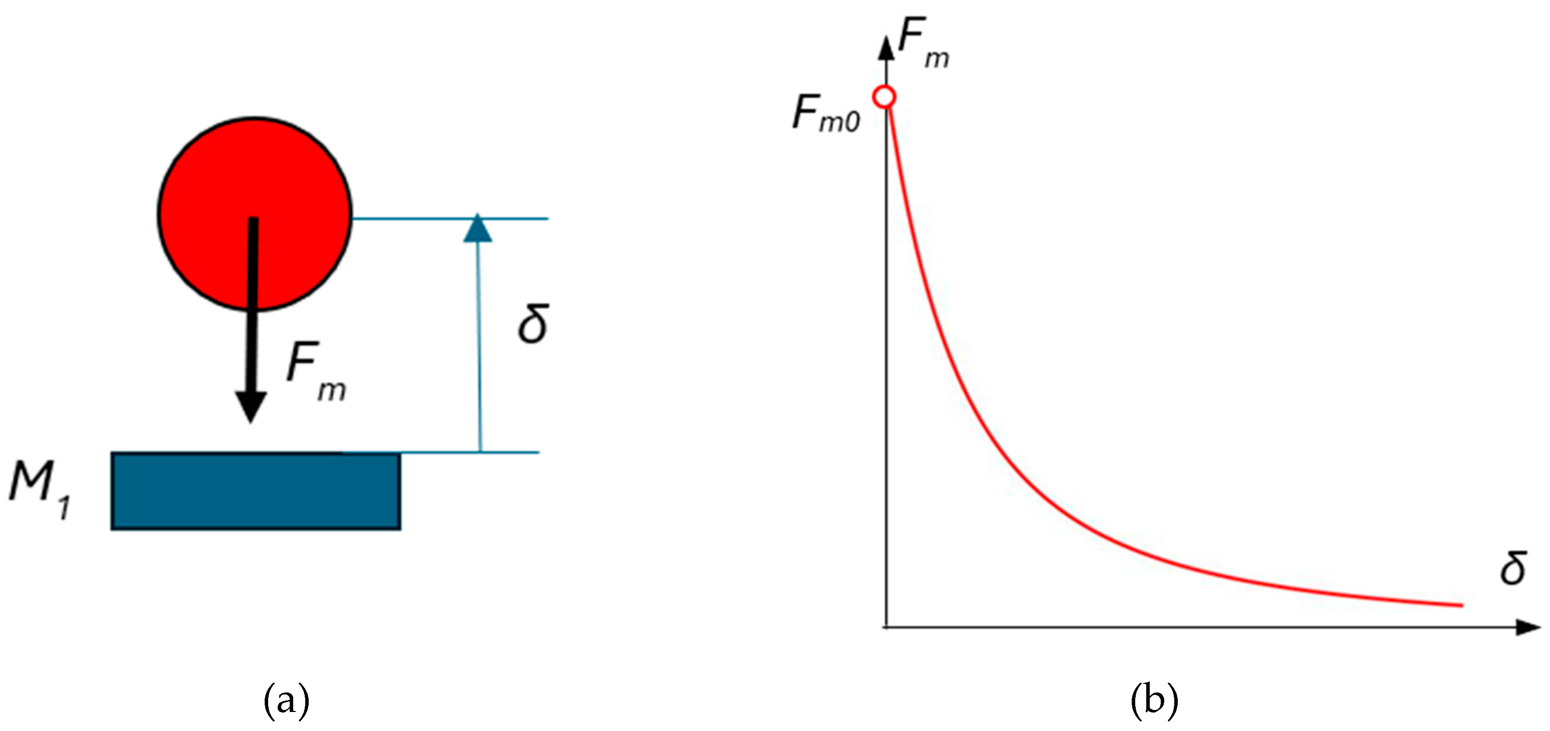
Figure 4.
The force of the permanent magnet located in the energy harvester acting on a ferromagnetic mass А mounted on a filament of SMA.
Figure 4.
The force of the permanent magnet located in the energy harvester acting on a ferromagnetic mass А mounted on a filament of SMA.
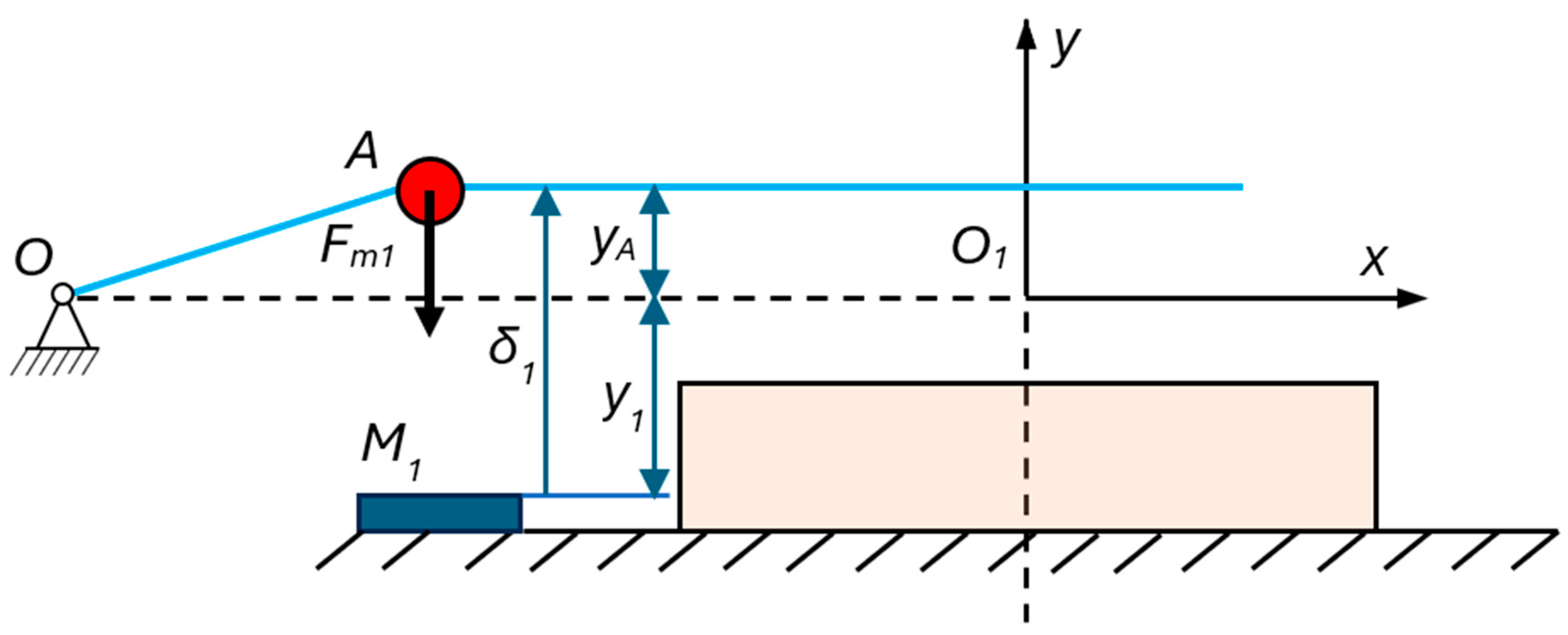
Figure 5.
Experimental setup of the thermoelectric energy harvester: (a) Schematic and overall concept; (b) Top view of the whole experimental setup (c) Partial view of the left side (d) Partial view of the right side of the energy harvester. 1. Variable load resistors, 2. PVDF cantilever. 3. Horizontal position sensor, 4. Ferromagnetic mass, 5. Heater, 6. Vertical position sensor, 7. SMA filament, 8. Right support, 9. Ohmmeter, 10. Permanent magnet stack.
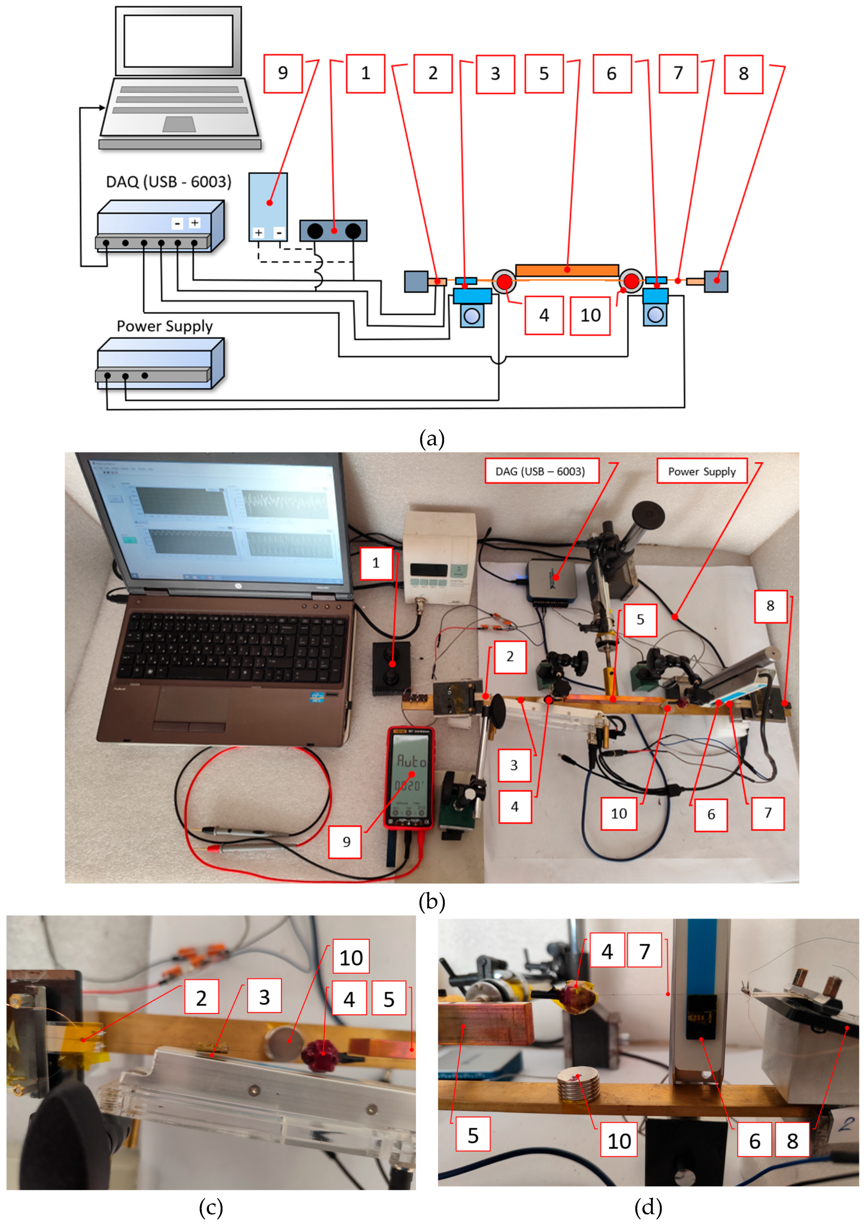
Figure 6.
Comparison between the output voltages obtained experimentally at heater temperature 70°C and load resistor of 5.5 MOhms: (a) Output voltage of the energy harvester without magnets; (b) Output voltage of the energy harvester with magnets.
Figure 6.
Comparison between the output voltages obtained experimentally at heater temperature 70°C and load resistor of 5.5 MOhms: (a) Output voltage of the energy harvester without magnets; (b) Output voltage of the energy harvester with magnets.
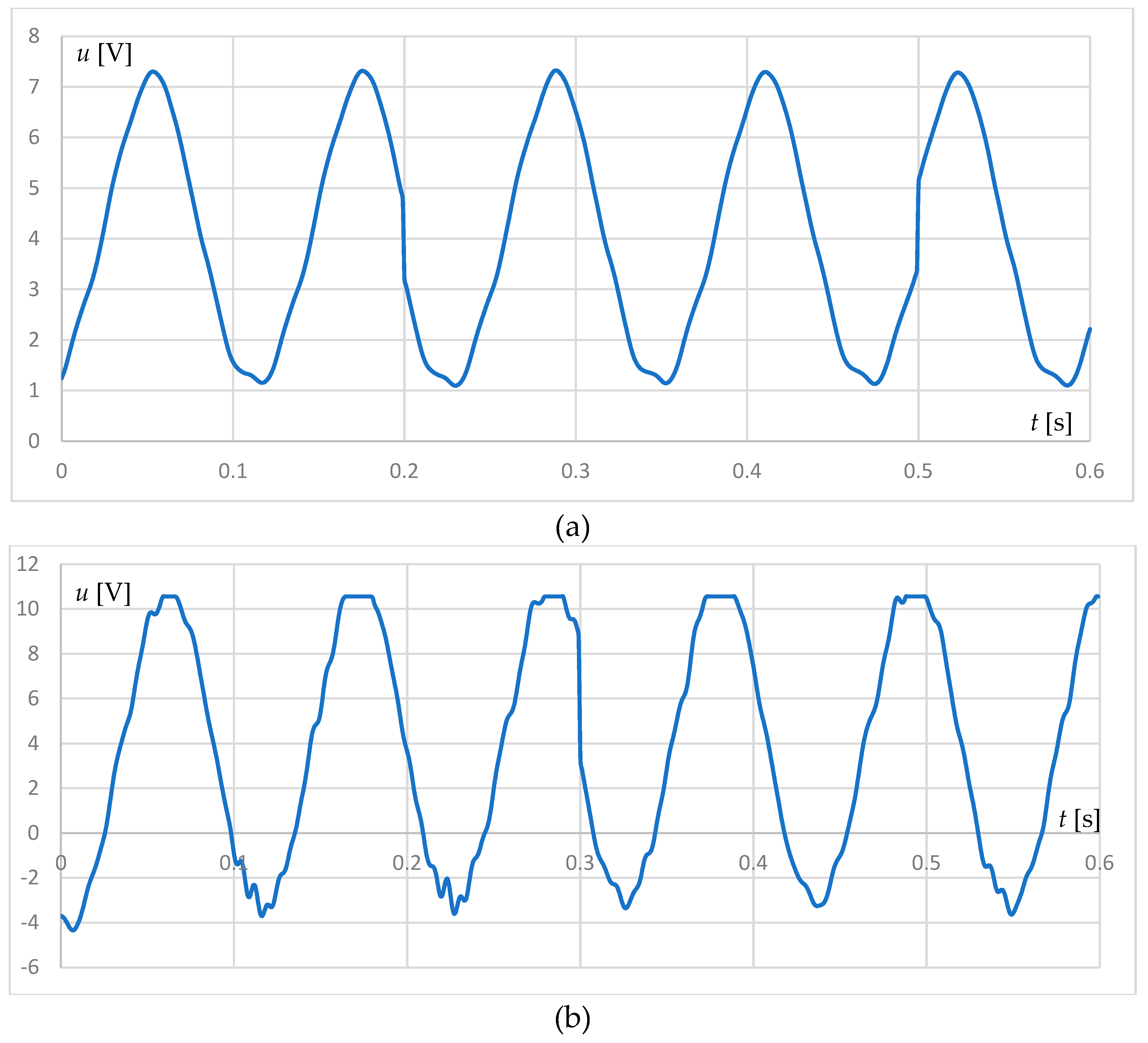
Figure 7.
Comparison between the output rms voltages add the power obtained experimentally at heater temperature 70°C: (a) Output rms voltage and power of the energy harvester without magnets; (b) Output rms voltage and power of the energy harvester with magnets.
Figure 7.
Comparison between the output rms voltages add the power obtained experimentally at heater temperature 70°C: (a) Output rms voltage and power of the energy harvester without magnets; (b) Output rms voltage and power of the energy harvester with magnets.
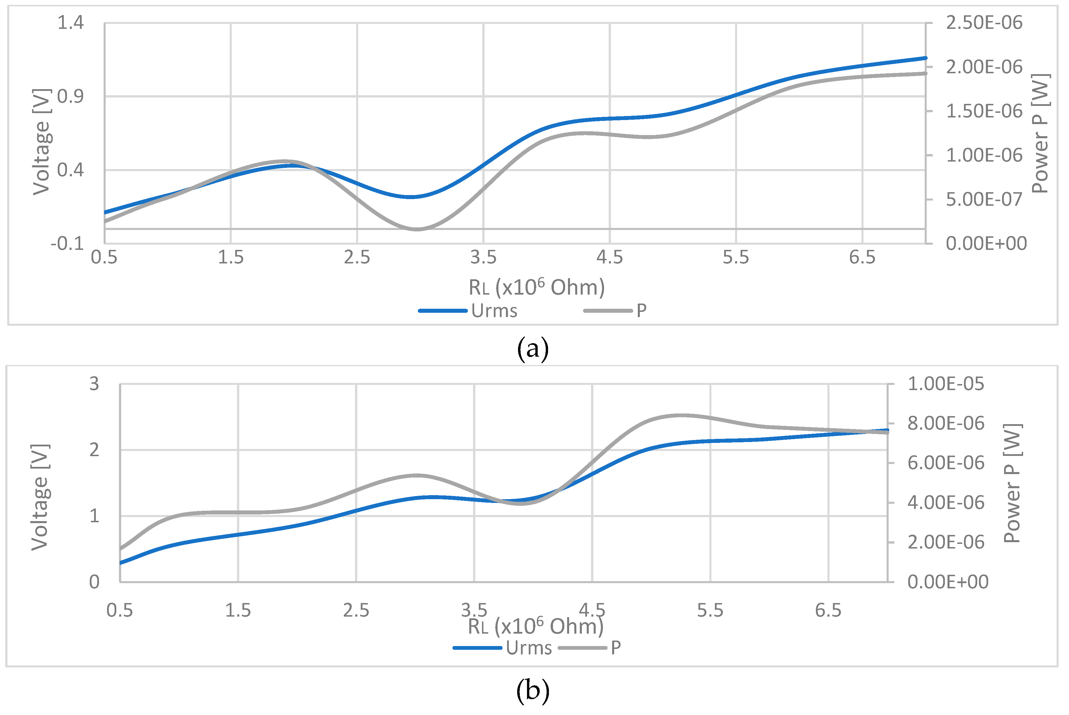
Figure 8.
Comparison between the experimental and theoretical results obtained at heater temperature 70°C and load resistance 500 MOhms: (a) Experimental rms voltage; (b) Experimental vertical displacement y of the ferromagnetic mass; (c) Experimental horizontal displacement x of the ferromagnetic mass; (d) Theoretically obtained rms voltage; (e) Theoretically obtained vertical displacement y of the ferromagnetic mass; (f) Theoretically obtained horizontal displacement x of the ferromagnetic mass;.
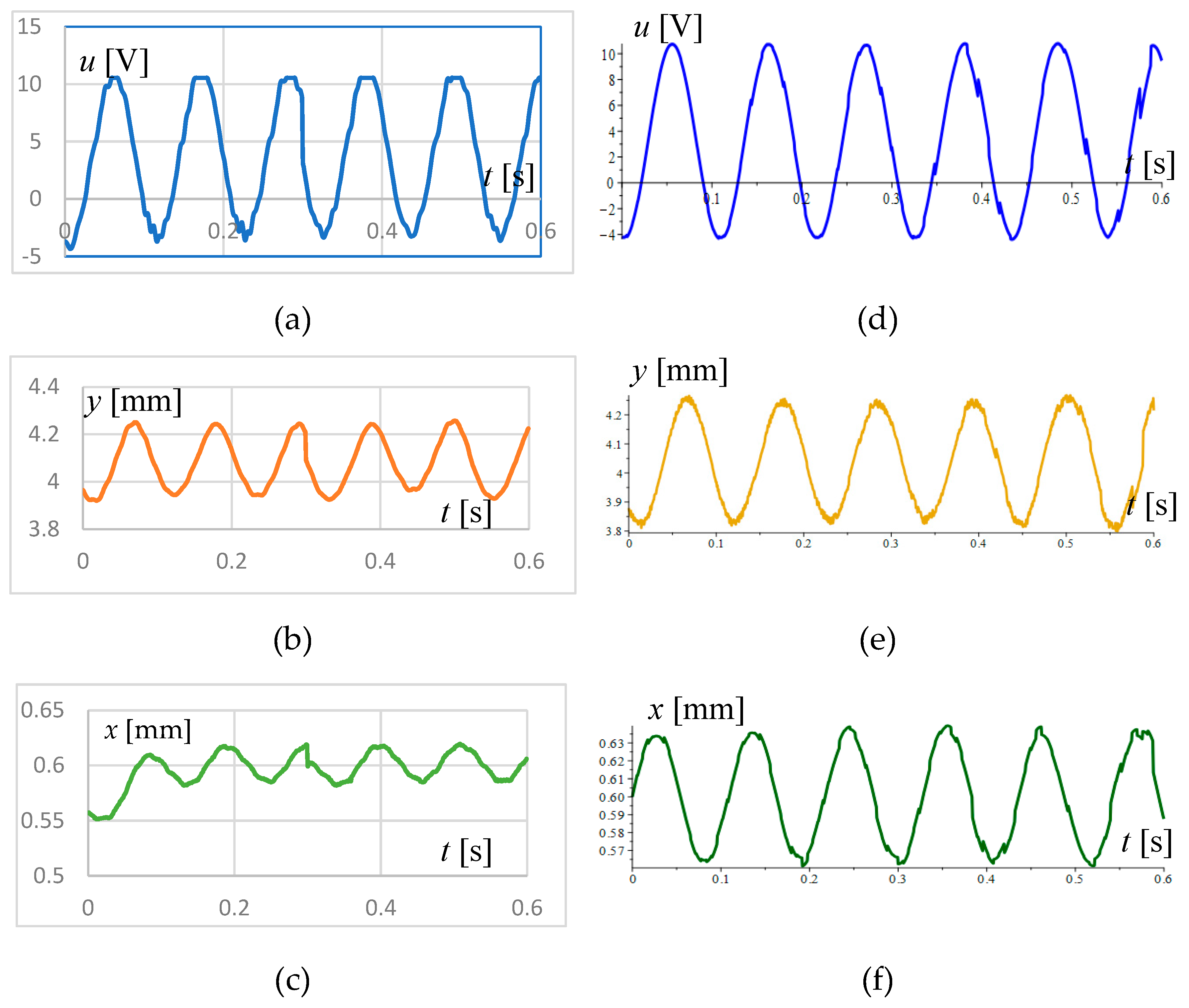

Table 1.
Numerical values of the parameters for the solution of system of ordinary differential equations (42).
Table 1.
Numerical values of the parameters for the solution of system of ordinary differential equations (42).
| Parameter | Symbol | Value | Unit |
|---|---|---|---|
| Imaginary magnetic mass | 8.14×10⁻⁵ | Nm2 | |
| Imaginary initial gap and | 0.00032 | m | |
| Translation magnetic coordinate | 0.010 | m | |
| Gap between the electrodes of the piezoelectric cantilever | 28 × 10−9 | m | |
| Length of the piezoelectric cantilever | 0.0235 | m | |
| Piezoelectric cantilever width | 0.0102 | m | |
| Dielectric permittivity of PVDF | 9.7396 × 10⁻¹¹ * | F/m | |
| Compliance of the piezoelectric cantilever under constant electric field | 0.384 × 10⁻¹⁰ * | Pa−1 | |
| Piezoelectric constant of PVDF | −27.1 * | pC/N | |
| Electromechanical coupling coefficient of PVDF | 16 * | % | |
| Longitudinal Young’s modulus of PVDF | 2.5 * | GPa | |
| Half-distance between the supports | l | 0.026 | m |
| NiTi filament half-length | ls0 | 0.25 | m |
| Mass of the sphere | m | 3.5 × 10⁻³ | kg |
| Gravity acceleration | g | 9.81 | m/s2 |
| NiTi filament end lengths | 0.14 | m | |
| Length of the middle section of the NiTi filament | 0.24 | m | |
| Diameter of NiTi filament | ds | 0.00025 | m |
| Young’s modulus for NiTi in fully twined martensite | 21.7 ** | GPa | |
| Young’s module for NiTi in partially twined martensite | 0.56 ** | GPa | |
| Young’s Module for NiTi in detwinned martensite | 11.1 ** | GPa | |
| Young’s Module for NiTi in austenite | 55.5 ** | GPa | |
| Yield strain for twined martensite | 0.0024 ** | -- | |
| Minimum strain of twinned martensite | 0.0044 ** | -- | |
| Starting austenite temperature of NiTi | 55.99 ** | °C | |
| Final austenite temperature of NiTi | 64.05 ** | °C | |
| Starting martensitic temperature of NiTi | 25.24 ** | °C | |
| Final martensitic temperature of NiTi | 21.44 ** | °C | |
| Austenite correction temperature | 0.01 | °C | |
| Austenite coefficient | 1.95 | -- | |
| Martensitic correction temperature | 0.01 | °C | |
| Martensitic coefficient | 2.17 | -- | |
| Start position of maximum temperature | 0.0095 | m | |
| End position of maximum temperature | 0.023 | m | |
| Conditional slope length | 0.0042 | m | |
| Room temperature | 20 | °C | |
| Maximum temperature of NiTi filament | 70 | °C | |
| Longitudinal damping coefficient | βx | 0.00042 | kg/s |
| Transverse damping coefficient | βy | 0.0014 | kg/s |
| Load resistance | From 1 × 10⁶ to 40 × 106 | Ω | |
| Initial speed along | 0 | m/s | |
| Initial speed along | 0 | m/s | |
| Starting position | −0.1 | m | |
| Starting position | 0.01 | m |
Disclaimer/Publisher’s Note: The statements, opinions and data contained in all publications are solely those of the individual author(s) and contributor(s) and not of MDPI and/or the editor(s). MDPI and/or the editor(s) disclaim responsibility for any injury to people or property resulting from any ideas, methods, instructions or products referred to in the content. |
© 2025 by the authors. Licensee MDPI, Basel, Switzerland. This article is an open access article distributed under the terms and conditions of the Creative Commons Attribution (CC BY) license (http://creativecommons.org/licenses/by/4.0/).
Copyright: This open access article is published under a Creative Commons CC BY 4.0 license, which permit the free download, distribution, and reuse, provided that the author and preprint are cited in any reuse.


