
Submitted:
22 May 2025
Posted:
23 May 2025
You are already at the latest version
Abstract
This study investigates how the Glock pistol emerged as the dominant design in modern handguns, despite its inventor's lack of prior experience in firearms design. It shows that Gaston Glock resolved a longstanding usability contradiction with the pistol he invented: combining the firepower and rapid reload capability of semi-automatic pistols with the safety and operational simplicity of double-action revolvers. Through a detailed reconstruction of the development process, the paper demonstrates how Glock applied a user-centered, solution-neutral approach, used iterative prototyping, and strategically leveraged functional integration and emerging manufacturing technologies. The resulting design was lighter, more reliable, simpler, and more cost-effective than its contemporaries. Drawing on these findings, the paper proposes a novel model for physical product evolution, in which innovation is driven by the gap between user-required and product-delivered usability. The model emphasizes the central role of the conceptual design and depicts the interaction of relevant entities in the innovation process. The Glock case illustrates how disruptive innovations can emerge from user-focused, iterative design – and offers a transferable framework for understanding dominant design emergence in engineering contexts.
Keywords:
disruptive innovation
; dominant design
; agile product development
; Glock
; product evolution
1. Introduction
While it may be unconventional to begin a scientific article with a quote from a YouTube video, the authors could not think of a better way to create interest in the subject and highlight its significance. In the video “The History and FUTURE of the Glock”, Isaac Botkin from the company T.REX Arms, a manufacture of a variety of different firearms accessories, comments on the title of Paul M. Barrett’s book “Glock: The rise of America’s gun” [1]:
“this [the Glock] didn’t actually become America’s gun. This became the next generation of how firearms are made. This became the next generation of how the entire world makes handguns. It’s not only America’s gun, because it is the world’s gun [emphasis added]. Every firearm manufacturer that used to make a steel-framed hammer fired gun – post Glock – also makes a Glock style firearm. (…) Glock pioneered a whole bunch of technologies [emphasis added] – not from scratch – but introduced them to the firearm industry in a way that they were universally adopted [emphasis added]. (…) Every single manufacturer from the pre-Glock era now makes a post-Glock era handgun. (…) the value of this gun is [that] the pure utilitarian engineering and manufacturing technology matures here. And thanks to Gaston Glock (…) every other firearms manufacturer has a clear path forward [emphasis added].” [2]
This quote not only aligns with the title of McNab’s book “Glock: The World’s Handgun” [3] but also reflects the authors’ conceptualization of a disruptive product innovation1, defined as the introduction of a novel dominant design, including new solution-determining working principles and structures as well as new geometric layouts, which is subsequently adopted by all major competitors, thereby displacing the previous dominant design [4]. Consequently, a disruptive innovation represents a pivotal shift, effectively dividing time into an era “before” and “after” by transforming the design, manufacturing, and use of products within the respective category [4].
This onset gives rise to three fundamental research questions that are investigated in this paper:
Research Question 1: What Made the Glock the Most Successful Handgun in the World Today?
What were the distinct features of the Glock pistol that made it “America’s most popular handgun” [5] with a market share of around 65 % in the US law enforcement and civilian handgun market and led to its adoption by a large number of militaries and special forces around the world? How has the Glock, initially perceived as a “mechanical oddity” [6], evolved into “an icon of power and glamour” [6], sold more than 20 million times influencing popular culture as evidenced by numerous references in films and songs [7], virtually becoming a generic reference for handguns in general? Why is there an own documentary film about the Glock the title of which referring to it as the “Weapon of Choice” [8]? And why did even an editor of the journal “Psychiatry” feel compelled to write a review about Paul M. Barrett’s book on the rise of the Glock pistol, concluding that it is a “projective test, ripe with details and issues that cry out for thought, discussion, and analysis” [6]? Addressing the first research question leads directly to the second:
Research Question 2: How Was the Glock Developed?
How did a man with no prior experience in firearm design succeed in developing a pistol that would go on to define the dominant design of modern handguns and the way they are made [9]? Furthermore, why did established firearm manufacturers – some with over a century of expertise in handgun design and production – fail to conceive a similar innovation? The fact that a pistol is a purely mechanical product only consisting of levers, joints, springs and guides, makes it even harder to comprehend why the incumbents failed to invent something like the Glock pistol. Though Glock was working with the same “toolbox” as the incumbents, he produced a conceptual design both principally unique and superior in its operation to anything established designers had yet invented. At the same time, the low complexity of the development object makes the case even more attractive for an in-depth investigation: In contrast to the development of a complex mechatronic product, not only is the development result easy to understand, but the development process can also be traced very well due to the small number of players involved and the short development time. This possibility gives rise to the third and final research question:
Research Question 3: What Broader Insights Can Be Drawn from the Development of the Glock Pistol?
Which insights can be extracted from examining the development of the Glock pistol as a case study that transcend firearm design and offer a foundation for a generic theory of disruptive innovation that can be applied to other products and industries?
Addressing the aforementioned research questions has presented the authors with a particularly intriguing example of disruptive product innovation, where “the American entrepreneurial dream was occurring in a garage in Austria” [6]. The lack of scholarly attention to this case may be due to the fact that the product in question belongs to a category that elicits strong reservations and is closely associated with significant political controversies. Thus, the authors have adhered to the principle of approaching the subject from a purely engineering design perspective, mirroring the unbiased solution-neutrality with which Gaston Glock approached the development of his first pistol more than forty years ago. From this perspective, a handgun can be seen as a mobile device in which the human-machine interface constitutes a significant component of the overall design – similar to a mobile phone – but with very specific requirements for safe operation, as it is often used in high-stress situations where incorrect handling can have fatal consequences.
This paper is structured around the three research questions outlined above. Following a presentation of the methodological approach including the materials analyzed and evaluated in the next section, the results corresponding to each research question are presented and discussed in the subsequent three sections. The study concludes with a summary of key findings.
2. Methods and Materials
To address the research questions, a “reconstructive case” approach [10], also referred to as “history” by [11], was selected. This methodology was chosen to investigate the “why,” “what,” and “how” within a complex system characterized by numerous interrelated decision-making and implementation variables. The objective was to develop a comprehensive and holistic understanding of a notable success case. Accordingly, a “holistic single-case design” [11] with theoretical sampling was employed.
An international and interdisciplinary core research team was assembled, comprising two mechanical engineering experts and one expert each in innovation management and industrial engineering. These individuals are the authors of this study. Team members were based in Austria, Germany, and the United States, facilitating a comprehensive linguistic and contextual understanding of both written and oral sources [12]. Within this team, sub-groups were formed to conduct the specific analyses described below. Partial findings were discussed in detail during collaborative workshops, where contradictions were addressed and consensus reached to eliminate rival explanations.
A standardized case study protocol was employed across all research activities to ensure consistency and comparability. All data and individual research outputs were systematically documented in a centralized database accessible to all team members. Methodological triangulation was achieved through the use of multiple data sources, enhancing construct validity and enabling cross-validation. Interdisciplinary collaboration was facilitated through regular joint workshops, and a “devil’s advocate” role was formally assigned during group discussions to challenge assumptions and mitigate confirmation bias. Chains of evidence were established to support findings, following procedures outlined by Stake [13]. Preliminary results were reviewed by subject matter experts in handgun development to validate interpretations.
Additional academic and industry specialists were consulted to address specific aspects of design and manufacturing. These included experts in plastics technology, machining, stamping, and bending, who provided validation for material choices and assessed the manufacturability and cost-efficiency of individual components.
Beyond physical analysis of the Glock 17 artifact, the study incorporated a wide range of documentary sources, including peer-reviewed literature, popular science publications, corporate documents, official public records, patents, and online resources. A systematic literature review was performed using the keywords “Glock*” in combination with “handgun*,” “gun*,” “pistol*,” and “firearm*” within the German Joint Library Network catalog (Verbundzentrale des Gemeinsamen Bibliotheksverbundes), as well as in Google, Google Scholar, and ProQuest. Special attention was given to statements and interviews involving Gaston Glock (cf. [14,15]), and to publications authorized by him (cf. [16]). These sources underwent qualitative analysis, and statements were clustered thematically.
All secondary analyses were independently conducted by at least two researchers and subsequently shared with the entire research team. Any discrepancies were resolved through workshop discussions. Furthermore, an expert interview was conducted with Dr. Ingo Wieser, a former specialist at the Austrian Armed Forces Weapons and Ammunition Test and Research Centre. Dr. Wieser played a pivotal role in the comparative evaluation of service pistols and was directly involved in testing early Glock prototypes during the Austrian military’s procurement process. Technical representatives from Glock GmbH also contributed by participating in in-depth technical discussions.
The study’s analytical framework was structured into three focal areas: (1) the product (Glock 17), (2) the development process, and (3) the market, customer base, and competitive environment.
(1) Product Analysis
The product analysis included four primary components: (a) patent analysis, (b) reverse engineering, (c) simulation-based functional analysis using CAD models, and (d) comparative benchmarking against competitor products. The analyses collectively focused on the product architecture of the Glock 17, particularly on the design of its individual components and the composition of its assemblies. Special attention was devoted to the human-product interaction, especially regarding ergonomics and usability in operational contexts.
a) Patent Analysis
This study introduces a methodological approach that reconstructs a prototype-based, iterative-agile development process through systematic patent analysis. Patents from multiple stages of the patenting process were examined, focusing on both technical drawings and textual descriptions, to trace the design evolution of the Glock 17 and to understand the design decisions underlying its development. Special attention was given to the allocation of functions to components, with particular emphasis on the principle of functional integration (cf. [17,18]). This method facilitated an understanding of the rationale behind the final product architecture [19].
b) Reverse Engineering
Due to the product’s purely mechanical structure and limited number of components, reverse engineering provided a detailed understanding of part design, functional interactions, and overall system configuration [20,21]. Innovative features of the Glock 17 were identified and contextualized through comparison with earlier handgun models. Additionally, material properties and geometric characteristics were used to infer the underlying manufacturing processes and, to a limited extent, potential cost structures.
c) Simulation-Based Functional Analysis
Existing CAD and multi-body simulation models were analyzed to examine dynamic interactions among components, enhancing the understanding of system-level functionality. These simulations served as digital prototypes for exploring mechanical behavior and operational sequencing.
d) Comparative Product and Requirements Analysis
A historical analysis of handguns developed over the past century provided context for benchmarking the Glock 17. This comparative framework facilitated the evaluation of its technological innovations. To further understand user requirements, tender documents from the Austrian Armed Forces were reviewed, along with period-specific evaluations found in gun magazines (cf. [22,23]). These sources helped triangulate functional expectations and usability perceptions from both institutional and end-user perspectives.
(2) Analysis of the Development Process
The development process of the Glock 17 was reconstructed through a qualitative analysis of both primary and secondary sources, including patent documents, chronological accounts from independent publications (e.g., [1]), and authorized narratives (e.g., [16]). Further contextual insights and validation were obtained through an expert interview with Dr. Wieser, which also enhanced the understanding of the collaboration between Gaston Glock and the Austrian Army during the design process.
To better understand the competencies underlying the development effort, the educational and professional backgrounds of key figures – especially Gaston Glock – were examined. This analysis also considered the company’s prior product lines (e.g., military knives) and its expertise in manufacturing hybrid products combining polymer and steel.
(3) Market, Customer, and Competitor Analysis
Market data were analyzed to assess the Glock 17’s commercial impact, including sales figures and segmentation trends within the handgun industry [24]. Special emphasis was placed on the product’s rapid adoption across military, law enforcement, and civilian segments. Key differences and commonalities in user requirements were identified and mapped across these groups.
Building on the analyses 1-3 presented above, the theoretical model delineated in Section 5 was systematically derived and iteratively refined through abstraction during a series of structured workshops, following the case study methodology proposed by Eisenhardt [25]. The model emerged through incremental comparison of empirical findings from the Glock case with established theoretical frameworks (e.g., [26]). In parallel, qualitative coding of the data facilitated the identification of recurring themes and explanatory patterns within the case (“within-case analysis”), which were subsequently synthesized and elaborated through the emerging model. To assess the broader applicability of the findings, a comparative analysis was conducted using the development of the first iPhone as a reference case – another landmark disruptive innovation [4]. A tabular comparison highlighted notable parallels in environmental changes, innovation trajectories, and outcome characteristics (“cross-case patterns”), thereby reinforcing the theoretical generalizability of the proposed model.
3. Key Factors of the Glock Pistol in Defining the Dominant Design for Handguns
3.1. Resolution of a Long-Standing Key Usability Contradiction
The groundbreaking core innovation of the Glock pistol lies in its safe action trigger system, which has resolved a “key usability contradiction” [4] that has existed since the invention of (semi-) automatic pistols: combining the firepower and rapid reload capability of semi-automatic pistols with the safety and operational simplicity of double-action revolvers. Specifically, it represents the development of a pistol that, once chambered, remains both ready to fire and safe to carry at all times, with a consistent trigger pull optimized for both safety and performance – light enough to enable rapid and accurate shooting, yet sufficiently heavy to minimize the risk of accidental discharge. To understand this key usability conflict and its increasing relevance in the early 1980s, it is essential to examine the functional differences between pistols and revolvers, as well as the technical and social changes that preceded the development of the Glock pistol.
Pistols vs. Revolvers
Handguns can generally be classified into two main categories: (semi-)automatic pistols, referred to hereafter as “pistols”, and revolvers. As this study does not aim to provide a comprehensive analysis of all handgun types, the term “revolver” in the following discussion refers exclusively to double-action revolvers.
A double-action revolver is characterized by a rotating cylinder that typically holds six cartridges. With a single, continuous pull of the trigger, two mechanical actions occur:
(1) The cylinder rotates, aligning a new chamber – containing a fresh cartridge – with the firing pin.
(2) The trigger mechanism both cocks and releases the hammer. As the hammer moves backward, it compresses the hammer spring, storing potential energy. Upon release, this energy is converted into kinetic energy, propelling the hammer forward to strike the primer, which ignites the propellant and discharges the shot.
After a shot is fired, the hammer spring is decompressed, and, in most revolvers, an additional safety mechanism prevents direct contact between the firing pin and the cartridge in the cylinder. The double-action mechanism necessitates a long, heavy trigger pull, which is both an advantage and a disadvantage. On the one hand, the long and heavy trigger pull makes it virtually impossible to accidentally discharge the gun while carrying, holstering or drawing, thereby eliminating the need for a manual safety mechanism. Thus, a double action revolver is always in the state of being ready to fire (given that the cylinder is loaded with cartridges) and safe to carry. On the other hand, such a trigger pull makes rapid and precise shooting more challenging. While most revolvers allow for single-action operation – where the hammer can be manually cocked for a lighter and shorter trigger pull – this approach is impractical in police or self-defense scenarios, where quick follow-up shots are often necessary. A second major limitation of revolvers is their relatively low firepower, resulting from both the limited ammunition capacity of the cylinder and the inherently slow reloading process. Even with the aid of a speed loader, reloading remains more cumbersome compared to magazine-fed semi-automatic pistols.
In contrast, a semi-automatic pistol uses a detachable magazine that – depending on caliber and design – can typically hold significantly more ammunition than the cylinder of a revolver and allows quick reloading by changing the magazine. The term automatic refers to the defining function of a pistol: it harnesses the energy generated by firing a round to automatically cycle the slide, ejecting the spent casing, chambering a new round and cocking the trigger mechanism, with the latter step excluded in double-action-only designs. The most common design for service pistols prior to the introduction of the Glock was the double-action/single-action (DA/SA) pistol. Like double-action revolvers, these pistols can also be carried safely, yet ready to fire. They were intended to be carried with a fully decompressed hammer spring that has no potential energy to ignite the primer and discharge a round. At the same time, the double-action mechanism of the trigger allowed to fire a shot by pulling the trigger. The first shot, fired in double-action mode, requires a longer and heavier trigger pull, as the trigger must both cock and release the hammer. All subsequent shots are fired in single-action mode, where the hammer is already cocked by the cycling slide, resulting in a shorter and lighter trigger pull. This transition between different trigger pull weights can negatively impact accuracy and shot consistency. Furthermore, additional operating steps are required after chambering a round by racking the slide as well after a shot is fired to decock the hammer before the pistol can be safely holstered. These additional operating steps, which will be discussed in more detail later, complicate the safe operation of the gun and pose potential sources of operating errors, particularly in high stress conditions.
Previous approaches to resolve the usability contradiction
Since pistols were initially developed primarily as cavalry weapons in military contexts, ensuring both safe carry and immediate readiness for use has been a fundamental challenge from the outset. Firearm designers have explored various mechanisms to address this issue. Figure 1 illustrates the operating steps of various pistol concepts necessary to transition a drawn weapon from its intended carrying condition to firing the first shot, as well as the weapon’s state after the first shot has been fired.
Single-action-only pistols, in which the trigger mechanism cannot be cocked by pulling the trigger alone, typically require an additional step before they are ready to fire. Early designs, such as the SIG Chylewski and the Jo.Lo.AR, were intended to be carried with an empty chamber and an uncocked trigger mechanism. To facilitate one-handed operation, both firearms incorporated innovative mechanisms that allowed the slide to be racked using only the firing hand. In the SIG Chylewski, this was achieved by pulling back the trigger guard with the trigger finger, while the Jo.Lo.AR omitted the trigger guard entirely and introduced a lever in front of the trigger that could be manipulated with two fingers of the firing hand. These mechanisms enabled the user to chamber a round and cock the trigger mechanism in a single motion, rendering the pistol ready to fire. However, after firing, both designs required multiple manual steps to return the weapon to a safe carry condition.
The renowned Colt M1911A1, another single-action-only pistol and the standard-issue sidearm of the U.S. military from 1926 to 1985, was designed to be carried in the “cocked and locked” condition—that is, with a round chambered, the hammer fully cocked and the thumb safety engaged. Typically, a pistol in this state presents a safety risk, as the hammer spring stores sufficient potential energy to ignite the cartridge primer, and only minimal force is required to release the sear, potentially leading to an unintentional discharge.
To mitigate this risk, the Colt M1911A1 incorporated two independently operating safety mechanisms: (1) a passive grip safety located on the back of the grip, which prevents the trigger from being pulled unless the shooter firmly grips the pistol, thereby depressing the safety, and (2) a manually operated thumb safety in the form of a frame-mounted lever on the left side of the pistol. When engaged, the thumb safety locks the sear, preventing the hammer from falling and the firearm from discharging. Upon drawing the pistol, a swift downward motion of the firing hand’s thumb disengages the safety, rendering the weapon ready to fire. Reholstering the firearm safely requires only reactivating the thumb safety, while the hammer remains fully cocked.
In the Heckler & Koch P7, also a single-action-only pistol, the designers sought to enhance usability by integrating the additional step required to ready the firearm into an action already necessary for drawing it – gripping the weapon – thus eliminating extra operating steps. This striker-fired pistol had a grip cocking mechanism, a safety lever integrated into the front of the pistol grip, which was operated by the three fingers around the pistol grip. The firing pin spring was automatically cocked by firmly gripping the pistol and decocked when the grip was released. Unlike traditional double-action/single-action (DA/SA) pistols, this design ensured a consistent trigger pull for every shot. However, this system presented practical challenges as it is difficult to move the three fingers surrounding the pistol grip independently of the trigger finger, particularly as a considerable force of approximately 700 N was required to operate the grip cocking mechanism [27]. In addition, with such a pistol, the safety is always disengaged when the grip is firmly held, and a shot can be fired in single action mode with a relatively light trigger pull. This also applies to the process of drawing and holstering the gun. As gripping the gun is the first step in drawing and releasing the grip is the last step in holstering, the gun remains fully cocked throughout these entire processes. As a result, several accidental discharges have been documented when the P7 has been used as a service weapon by various police departments in Germany [28].
Another approach to resolving the usability contradiction and combining the advantages of both revolvers and a semi-automatic pistols, was the development of double-action-only (DAO) pistols, such as the Smith & Wesson Model 5946 and the Beretta 92D, both manufactured throughout the 1990s. In these firearms, the recoil energy was used exclusively for ejecting the spent casing and chambering a new round. However, cycling the slide did not tension the hammer spring; it remained fully decompressed, regardless of whether the slide was manually racked or cycled after each shot. Like double-action revolvers, these pistols automatically returned to a safe-to-carry condition after each shot, thereby eliminating the need for the additional decocking procedures required in double-action/single-action pistols. However, this design inherited a major drawback from the double-action revolver: the consistently high trigger pull required for each shot, which severely compromised rapid and accurate shooting, leading some to even describe this concept as “the worst combination of both types” [29].
Resolution of the usability contradiction by the Glock pistol
The Glock pistol at the time of its introduction was the only design that successfully resolved the key usability contradiction described at the beginning of this section. Once the slide was racked, the pistol remained in a state that was both ready to fire and safe to carry (Figure 1). Additionally, the Glock pistol maintained a consistent trigger pull weight within the optimal range for every shot, balancing safety and the facilitation of fast and accurate shooting. The U.S. patent for the Glock pistol demonstrates that Glock identified the key usability contradiction during development and addressed it deliberately, as evidenced by the following excerpt from the “Summary of the Invention” section:
“Handling of the pistol according to the instant invention is therefore as simple as possible. The pistol is ready after chambering of the cartridge in the barrel for shooting at any time and is nonetheless completely safe from unintentional shots. Similarly in this condition the pistol is fully drop- and jar-resistant. As a result of the unchanging trigger force accuracy is increased. Simple and safe handling of the pistol is ensured even for the unpracticed user.” [27]
The usability contradiction was resolved through two key innovations in the Glock pistol: (1) a striker-fired mechanism in which the striker spring is only partially cocked after each shot, with a counteracting trigger spring assisting the trigger pull, and (2) a trigger bar capable of movement in two non-parallel directions, allowing it to both tension the striker spring and control the locking and release of the firing pin. We first examine the trigger mechanism, which is controlled by the counteracting forces of the striker spring and the trigger spring.
The Glock’s striker-fired mechanism is only partially cocked after chambering a round and following each shot. The potential energy stored in the striker spring remains in a subcritical range, meaning that when converted, it is insufficient to impart the striker with the kinetic energy required to ignite the primer. The preloaded striker system was inspired by the trigger mechanism of the ROTH/KRNKA M.7 pistol (cf. [40,41]). However, a purely partial preloading of the striker spring – such as in the ROTH/KRNKA M.7 – would have been merely a compromise and would not have fundamentally resolved the usability contradiction. A striker spring that is preloaded within the subcritical range increases the safety of the pistol and reduces the required trigger travel but does not lower the trigger pull weight necessary for firing. The key innovation in the Glock pistol was the implementation of a second spring, the so-called trigger spring, which acts on the trigger bar and pulls it backward when the trigger is actuated (Figure 2). This trigger spring generates a pulling force that supports the shooter’s trigger movement, which must fully tension the striker spring before firing. Consequently, the shooter only needs to apply a force to the trigger that results from the difference between the opposing compressive force of the striker spring and the assisting tensile force of the trigger spring. By incorporating the trigger spring, an additional degree of freedom is introduced, allowing the trigger force to be independently adjusted at a given striker spring preload2:
“The trigger or cocking force is the difference between these spring forces [the forces exerted by the firing pin spring and the trigger spring] and can be set at a hair trigger or a relatively stiff novice level.” [27]
From a design theory perspective, Glock identified a usability contradiction, formulated a corresponding development task, extracted the central technical/physical contradiction, and ultimately resolved it (Figure 3). The solution exemplifies the application of the TRIZ (Theory of Inventive Problem Solving) principle of “Separation in Space”. This principle is one of four TRIZ separation principles used to resolve physical contradictions that arise when a system or component must simultaneously exhibit opposing properties. In the case of the Glock pistol, the striker spring presents a physical contradiction: it must store sufficient potential energy to ignite the primer while maintaining a low trigger pull weight – two requirements that are at odds. A low spring constant facilitates easier tensioning (i.e., reduced trigger pull weight) but fails to store enough energy for ignition. Conversely, a high spring constant ensures sufficient energy storage but increases the trigger pull force. Integrating both functions into a single spring at a single location would inevitably compromise either trigger pull weight or striker force.
The “Separation in Space” principle resolves this contradiction by spatially distributing the functions across separate components. In Glock’s design, two distinct springs serve complementary roles:
- The striker spring – stores the energy required to ignite the primer when fully compressed.
- The trigger spring – assists in reducing the force needed to pull the trigger.
This spatial separation, which enabled Glock to achieve both optimal energy storage for reliable ignition and an optimal trigger pull weight, constitutes the innovative core of the Glock pistol, as it represents a genuinely novel invention previously unseen in firearm design. Accordingly, it is explicitly referenced in the title of Glock’s U.S. patent: “Automatic Pistol With Counteracting Spring Control Mechanism” [27].
From a systems engineering perspective, after firing, only part of the harvested recoil energy is stored in the striker spring, while another portion is stored in the trigger spring. The energy stored in the trigger spring remains in a secure bypass state and can only be accessed through deliberate actuation of the trigger (Figure 4).
The trigger bar serves as the core component of the trigger system, integrating multiple functions (Figure 5). It moves both backward and downward, performing three functions that were traditionally carried out by separate components in firearms prior to the Glock’s introduction: (1) tensioning the striker spring, (2) locking the firing pin, and (3) acting as a sear to release the firing pin. Additionally, during the trigger pull, the trigger bar deactivates both the firing pin safety and the drop safety. This functional integration, embodied in the trigger bar’s complex three-dimensional shape, eliminates the need for manually operated safeties and simplifies pistol operation to a single trigger pull. As a result, “the condition of the pistol is the same before the first shot as it is before the subsequent shots” [27] – both safe against accidental discharge and ready to fire. This design relieves the user from the task of operating a manual safety, thereby eliminating a potential source of user error.
How a Glock pistol functions
The following section details the complete cycle of the Glock pistol, illustrating its main components and operational states34 (Figure 6):
1. Rest State
At rest, the striker spring is partially compressed, while the trigger spring is fully tensioned. In this state, three independent safeties are automatically engaged. Two of these mechanisms specifically prevent unintentional movement of the trigger bar caused by inertial forces resulting from external impacts (e.g., dropping the firearm), the third one blocks the tip of the firing pin:
- (1)
- Drop/Jar Safety: This mechanism prevents forward and downward movement of the trigger bar, thereby blocking release of the firing pin, which is retained by the rear end of the trigger bar. This is achieved by securing the left arm of the cruciform sear plate within a cutout in the trigger mechanism housing, which also serves as the forward stop for the trigger bar (Figure 7).
- (2)
- Trigger Safety5: This mechanism inhibits rearward movement of the trigger bar induced by inertial forces, i.e., the same motion that occurs during an intentional trigger pull. It also prevents accidental discharge resulting from lateral pressure on the trigger.
This mechanism consists of a pivoted lever that protrudes through the trigger face and extends through the trigger body, emerging at the top rear where it contacts the frame, blocking a rearward movement of the trigger [23] (Figure 8). When the trigger is depressed, the safety lever pivots, causing its rear portion to move upward into the trigger body and disengage from the frame [23]. This allows the trigger to move rearward, facilitating discharge.
The inclusion of this safety is necessitated by Glock’s fundamental design principle, which involves two counteracting springs acting on the trigger bar: Since the trigger spring continuously exerts a rearward and upward force on the trigger bar, an external impact or lateral pressure on the trigger would only need to overcome the difference between the forces exerted by the striker spring and the trigger spring to cause an unintended discharge. The trigger safety prevents this by mechanically blocking rearward movement of the trigger – and, consequently, the trigger bar – unless the trigger is deliberately pulled. From a systems engineering perspective, it ensures that the energy stored in the trigger spring can only be released through a deliberate actuation of the trigger.
- (3)
- Firing Pin Safety: This mechanism consists of a spring-loaded plunger positioned in front of the firing pin, preventing forward movement of the firing pin (Figure 9) (see also section 4.3, stage 3 of patenting).
2. Trigger Pull – First stage: Safety releasing and cocking
As the user pulls the trigger, the trigger safety disengages, allowing the trigger and its connected trigger bar to move rearward. This movement compresses the striker spring further as the trigger bar engages a downward extension of the striker. Simultaneously, an upward extension of the trigger bar lifts the firing pin safety plunger, clearing the firing pin’s path. The rearward movement of the trigger bar is substantially assisted by the trigger spring, which progressively releases tension. Near the end of its stroke, the rear end of the trigger bar engages the cam surface of the connector. The trigger travel of this first stage is approximately 5,5 mm.
3. Trigger Pull – Second stage: Discharge
The cam surface of the connector forces the trigger bar downward, disengaging it from the firing pin extension6 (Figure 10). As a result, the fully compressed striker spring propels the firing pin forward, striking the primer and firing the cartridge. At this moment, the trigger spring retains residual tension. The trigger travel of this second stage is approximately 2,5 mm.
4. Slide Recoil (Rearward Movement)
The recoil force from firing the cartridge drives the slide rearward, compressing the recoil spring. As the slide moves, it carries the striker rearward until its extension is positioned behind the trigger bar. The rearward motion also forces the connector inward via a cam surface in the slide that engages with an upward hook of the connector, flexing it inward (the connector acts as a leaf spring, which is also reflected by its German name “control spring”). This mechanism enables the trigger bar to move upward again, surpass the connector cam surface, and retain the firing pin during the slide’s forward movement (Figure 11).
In many pistols, a separate component – the so called disconnector – disengages the trigger bar from the sear after a shot is fired, preventing multiple discharges from a single trigger pull and ensuring proper semi-automatic operation [44]. In the Glock design, where the sear function is already integrated into the trigger bar, the disconnector function is fulfilled by the interaction between the connector and the cam surface in the slide. This represents another example of functional integration in the Glock system, reducing the number of required components.
The upward movement of the trigger bar is primarily driven by the trigger spring, which pulls the trigger bar backwards and upwards, thereby fully relaxing. However, there is a second mechanism by which the trigger bar can be moved upwards again. Once the connector releases the trigger bar, it can be moved a little further back (approx. 0,29 mm) by applying continued pressure on the trigger. Contact between the S-curve of the trigger bar and a polymer grip surface, inclined backward at approximately 10 degrees, causes the trigger bar to slide 1,65 mm upward along this incline during its rearward motion. This elevation raises its rear end by approximately 3,73 mm, enabling retention of the firing pin and cocking of the striker spring. Said mechanism allows the Glock to continue firing even with a broken trigger spring, provided that the trigger is consistently pressed rearward throughout the slide cycle.
5. Slide Return (Forward Movement)
Once the slide reaches its rearward stop, the compressed recoil spring starts to propel it forward. As the slide returns, the striker extension re-engages the rear end of the trigger bar, recompressing the striker spring.
6. Trigger Reset
Releasing the trigger allows the striker spring, via its extension engaging the trigger bar, to push the trigger bar forward. The forward movement of the trigger bar re-tensions the trigger spring while partially decompressing the striker spring. It also allows the connector to flex outwards back in place, bringing its cam surface back in the path of the trigger bar and thereby enabling the downward movement of the trigger bar with the subsequent trigger pull. This resets the trigger. The system is now back in the rest state, ready for the next cycle, with all three safeties being automatically re-engaged.
When comparing the usability of the Glock pistol to two widely used representatives of the DA/SA pistol concept that dominated the market at the time of Glock’s introduction – the Beretta 92FS and the Sig Sauer P220 – it becomes evident how significantly Glock’s operating concept improves usability. Figure 12 illustrates the operational steps required to transition each pistol to its intended carry condition after inserting a loaded magazine, as well as their respective states after firing the first shot. The graphical representation clearly highlights differences in operational complexity. Unlike the Glock, both the Beretta and Sig Sauer require decocking after chambering a round and after firing a shot to ensure a safe carry condition. In the case of the Sig Sauer, which – like the Glock – lacks a manually operated safety, this is achieved via a decocking lever. The Beretta, equipped with a decocking safety, requires an additional step: after decocking the pistol using the safety lever, the safety must be disengaged by pushing the safety lever back up again to return the firearm to a ready-to-fire state. The Glock’s design eliminates these additional steps for the user and ensures that the firearm never enters an unsafe carry condition. This aligns with Thesis 7 from [4], which posits that disruptive innovations redistribute tasks within the human-product interaction system by shifting responsibilities from the user to the product, thereby reducing the user’s cognitive and physical workload.
The Safe Action System, described in the previous section, also serves as the foundation for a striker-fired design that is neither a double-action-only system, such as the Heckler & Koch VP 70, nor a compromise in safety. Since the primary advantage of an external hammer – indicating the trigger system’s status (i.e., whether it is cocked or not) – is rendered obsolete by this system, and given the external hammer’s several disadvantages, such as potentially obstructing the draw of the weapon, there is no longer a functional justification for its implementation.
3.2. Reciprocal Enablers – Innovation Emergence Through Synergistic Linkages
In addition to its novel operating concept, Glock integrated several key technologies across the three fundamental domains that determine a physical product’s realization and value proposition: geometric layout, materials, and production processes. While most of these technologies had been previously used in firearms (Figure 13), they had never been systematically integrated into a single system before. Their synergistic interaction led to a significant advancement in the usability of the Glock pistol as an emergent effect in line with systems theory. In this context, they function as “reciprocal enablers” as defined by [4]. In the following discussion of these reciprocal enablers, we will focus on those elements that were innovative, or at least unusual, in handgun design at the time of the Glock’s introduction, and that also contributed to its exceptional usability. Systems that were already widely adopted in other pistols, such as the modified Browning locked-breech short-recoil operating principle, will therefore not be analyzed in detail.
The most prominent feature of the Glock is the use of polyamide 66, a polymer material, for the pistol’s frame (Figure 14). While the Glock pistol was not the first handgun to incorporate a polymer lower receiver, its adoption of this still-uncommon material at the time attracted the most public attention. Following its introduction, widespread debates emerged regarding the potential undetectability of polymer firearms at airports, inadvertently providing the Glock pistol with significant free publicity [45]. Polymer materials offer several advantages over traditional metals in firearm construction. They are lightweight, cost-effective, corrosion-resistant, and possess greater elasticity than steel, allowing them to absorb some of the recoil energy. The choice of material also affects the domains of production process and geometric layout: polymers are inherently suited for injection molding, a manufacturing process that enables a high degree of design freedom and facilitates highly integrated product designs by allowing complex shapes to be produced cost-effectively. This integration reduces the number of components, minimizes assembly effort, and simplifies production. The high abrasion resistance required for the slide guide was achieved by casting in metal guides into the polymer frame. A key advantage of injection molding is its ability to create an ergonomically optimized grip as a single unit. Unlike metal pistol grips, which require additional grip panels, a polymer grip can maintain a slim profile even when accommodating a double-stack magazine, enhancing usability – particularly for individuals with smaller hands. Furthermore, the flexibility of the polymer frame allows it to compensate for minor tolerances in other mounted components, improving overall fit and function. As a result, the traditional trade-off between reliability and precision – where a pistol was either loose and reliable or tight and accurate but also prone to malfunctions – became obsolete.
Glock recognized manufacturing as the critical process through which a physical artifact is realized to meet customer needs. He optimized the design of his pistol for manufacturability to a level comparable to Toyota’s approach in the automotive industry. A notable example of this is the early adoption of CNC technology, which had only recently emerged in the late 1970s. The Glock slide is CNC-milled from a from a solid rolled-steel bar, with no welding or riveting, enabling a high degree of automation characterized by low labor costs and consistent quality. Additionally, this manufacturing approach allows for an advantage in the domain of the geometric layout: a further reduction in the number of individual parts, thereby minimizing assembly effort. Unlike designs such as the Colt M1911A1, the Glock slide features simple, straight lines, and its barrel consists of a rod with a rectangular chamber at the rear, eliminating the need to monitor complex tolerances during production (Figure 15.
Aside from the firing pin, which is machined, most of the Glock’s internal components are stamped and bent, a process that facilitates the cost-effective mass production of complex geometric shapes, such as the trigger bar. This approach contributes to a highly integrated product design, further reducing the number of parts. Although stamped and bent parts exhibit lower structural strength compared to machined components, this limitation is offset by a design optimized for load path efficiency. These components are engineered and positioned within the frame to primarily withstand tensile and compressive forces, resulting in high strength and stiffness along the principal load direction. Additionally, the work hardening effect inherent in stamping and bending was deliberately leveraged in specific parts to enhance structural integrity. As a result, the design effectively balances cost-efficient mass production with durability.
Glock selected a polygonal barrel design, which can be manufactured without cutting through hammer forging. Compared to conventionally rifled barrels – then the standard in handguns – the polygonal design provides a superior gas seal, resulting in higher bullet muzzle velocities. Additionally, polygonal barrels exhibit significantly greater service life due to reduced wear.
Glock was also the first to introduce ferritic nitrocarburizing to the firearms industry, applying it to the slide and the barrel of his pistol. This process, commonly referred to in the context of Glock as “teniferation” (derived from a brand name for salt bath nitrocarburizing), significantly enhances the steel’s fatigue resistance, abrasion resistance, and corrosion resistance7. At the time of the Glock pistol’s development, this technique was rarely used outside of high-end industrial applications, such as bearings, machine shafts, and machine-tool components [29]. The significance of this innovation was highlighted by Patrick Sweeney in his book “Glock Deconstructed”, where he remarked, “We certainly have to tip our hats to Gaston Glock for seeing that an obscure industrial process such as this could be applied to firearms and improve them greatly.” [29].
In summary, it can be said that Gaston Glock deliberately employed various manufacturing processes that were unusual at the time in the manufacture of handguns to enable the cost-effective realization of a highly integrated product design. The result was a pistol that was not only significantly lighter, more ergonomic, and more cost-effective than all competing products at the time, but had also significantly fewer parts, with only 348 parts, no screws and just two pivot pins. This small number of parts not only reduces the effort required for final assembly of the pistol but also significantly simplifies assembly and disassembly during use (“field strip”). Since the number of moving parts is a key determining factor for the reliability of a mechanical system, the small number of parts represents an important foundation for the reliability of the Glock pistol. Thus, from a design theory perspective, the Glock pistol demonstrates a significantly higher level of ideality, as defined by TRIZ, compared to all preceding competing models, thereby confirming Thesis 6 from [4].
3.3. The Formal Aesthetics of the Glock Pistol
The design language of the Glock pistol is characterized by a plain minimalistic design conveying durability, simplicity and clarity through geometric reduction and its black color (Figure 16). It is centered on ruggedness and functionality creating an austere purely purpose-driven technical aesthetic that speaks to strength and practicality. The design follows principles commonly seen in high-precision engineering, akin to industrial tools rather than traditional firearms. The Glock features a predominantly rectilinear form with clean, uninterrupted surfaces. The slide is a simple, box-like structure with straight, flat planes, avoiding unnecessary embellishments. The grip integrates subtle curvature for ergonomics but maintains an overall angular, utilitarian appearance. The overall appearance of the Glock very much resembles the bare minimum abstraction to symbolize a gun.
In [46] graphic designer Jill Butler describes the design language of the Glock pistol as follows:
“If I were going to buy a gun, I would want it to look like this one. The Glock’s single-color plastic body, matte finish, lack of details, and simple shape say, ‘I own the fact that I am a powerful tool designed and built to intimidate, maim, or kill, and I do not take that responsibility lightly.’ The Glock looks serious, subdued, and respectful. And if I were going to shoot a gun, that’s how I would feel.”
The Glock’s distinctly utilitarian design carries a masculine connotation, significantly influencing its perception in segments of popular culture where hypermasculinity is central to identity, particularly in action films and rap music. Within this cultural framework, the Glock is often regarded as the antithesis of firearm designs that incorporate superfluous features or excessive ornamentation, which are sometimes perceived as less functional or even effeminate. This perception is exemplified in the 1998 film “U.S. Marshals”, in which the protagonist, Sam Gerard, critiques a fellow officer’s stainless-steel pistol, remarking: “Get yourself a Glock and lose that nickel-plated sissy pistol!”. The succinct, one-syllable name “Glock”, which rhymes with frequently used words in rap music, such as e.g., “block” and “cop”, has also served as a catalyst for the pistol’s numerous references in popular culture [7]. The Glock pistol has become so ubiquitous in film and television that its image is now as recognizable as that of the Russian AK assault rifle, although the latter is depicted on several national flags and the Glock is not [29].
4. The Development Process of the Glock
4.1. The Key Person: Gaston Glock
Before analyzing the development process of the Glock pistol, it is essential to examine the individual who initiated and led this endeavor – Gaston Glock. His educational background and professional experience played a crucial role in shaping the expertise that ultimately contributed to the success of the Glock pistol. Gaston Glock was born in Vienna on July 19, 1929. In 1947, he graduated from the higher department for mechanical engineering at the Federal Vocational School in Vienna IV. While not an academic degree, this education combined technical instruction with practical vocational training, equipping him with foundational engineering skills. Following his graduation, Glock entered industry, starting in an entry-level manufacturing position with a company that produced hand drills [1]. Over time, he advanced through various roles in different companies, culminating in his position as factory manager at “Kühler- und Metallwarenfabrik” (Radiator and Metal Goods Factory) [1].
His career trajectory was marked by innovation, as evidenced by numerous patents he registered. These patents not only reflected his inventive mindset but also demonstrated his growing expertise in key technologies that would later be instrumental in the development of the Glock pistol. Many of his inventions focused on improving manufacturability and integrating innovative production techniques, demonstrating the extensive manufacturing expertise he developed throughout his career. The first patent listing Gaston Glock as a co-inventor was filed on November 26, 1953, on behalf of “BEHA Werk Metallwarengesellschaft m.b.H. in Vienna”. This patent pertained to a safety valve for pressure cookers [47] (Figure 17). Notably, the invention featured a sophisticated spring mechanism, highlighting his early proficiency in the design of spring-controlled mechanisms.
In 1963, Glock founded his own company, GLOCK KG, in Deutsch-Wagram, near Vienna. Despite already holding a managerial position that provided financial security and social standing, his decision to establish a company underscores his entrepreneurial drive [1]. Initially, the company, with just three employees, specialized in producing consumer goods made of wood, plastic, and metal, including door hinges, brass fittings, and curtain rods (Glock Gesellschaft m.b.H., 2023). During the 1970s, Glock KG expanded its scope to designing and manufacturing military equipment for the Austrian armed forces, such as practice hand grenades, field knives, and cartridge belts for machine guns [48]. This period marked the company’s increasing expertise in hybrid products combining polymer and steel. In 1977, Glock filed a patent for a training hand grenade featuring a hollow steel body coated in plastic [49]. The same year, he patented a field knife that would later become standard issue for the Austrian Army. The knife’s innovative design involves a blade shaft directly cast into the polymer grip, forming a secure, form-fitting connection that eliminated the need for screws, enhancing both durability and cost-effectiveness in manufacturing [50] (Figure 17). The structural design of this field knife bears striking similarities to that of the Glock pistol: both feature a polymer grip as the primary human interface and steel as the material for critical functional components – such as the blade in the knife and the slide and barrel in the pistol. Beginning in 1978, Glock supplied a large number of these knives to the Austrian Army, solidifying his reputation as a reliable contractor and establishing key relationships within the Austrian Ministry of Defense [16]. These connections would prove invaluable when, just a few years later, Glock embarked on the development of his groundbreaking pistol [16]. In the year 1980, at the onset of the development of the Glock pistol, GLOCK KG was reformed into “GLOCK Ges.m.b.H. – Kunststoffe, Metallwaren, chem. techn. Produkte”, which means “GLOCK LLC – Plastics, metal goods, chemical and technical products”, a name that officially signified the company’s focus on hybrid products integrating steel and polymer materials.
4.2. User-Centered Problem Space Exploration
Glock employed a highly systematic and methodical approach in developing his pistol. His lack of prior experience in firearm design proved to be an advantage, allowing him to approach the task impartially and with complete solution neutrality. He saw the handgun as merely another tool on a soldier’s belt, similar to the knives his company already produced [1]. In an interview, Glock stated, “That I knew nothing was my advantage” [15]. Furthermore, his company’s absence of a history in handgun manufacturing meant it was not constrained by existing production facilities, thereby avoiding technical lock-in. Established manufacturing capabilities can lead to cognitive solution fixation in product development, as designing products compatible with existing manufacturing processes is often easier and more cost-effective. The phenomenon that existing production facilities influence design decisions by constraining the perceived solution space, referred to as “cognitive gravitation” by [4], is vividly illustrated by the following quote from [44]:
“So how was it that Gaston Glock was able to get it right? One would argue he got it right because he hadn’t done it before. One of the largest problems in getting a new design accepted by an established manufacturer is (…) the ‘we don’t have the tooling’ syndrome [emphasis added]. Why invent something new when you can simply modify what you have?”
The early phase of development is characterized by extensive user-centered problem-space exploration. Remarkably, Glock combined conventional engineering design methods with user-centered approaches, such as the Lead User Method and Design Thinking, which were not yet described in the literature at the time [1,16]:
- Benchmarking and Reverse Engineering
Glock began with extensive benchmarking and reverse engineering. He acquired several state-of-the-art pistols, including the Beretta 92F, Sig Sauer P220, CZ 75, and a modern version of the Walther P38. He conducted intensive testing and tear-downs to analyze the manufacturing and assembly processes of these pistols.
- Patent Analysis
To gain a comprehensive understanding of the existing state of firearm design, Glock spent several weeks at the Austrian Patent Office, reviewing historical and contemporary handgun innovations.
- Expert Interviews
Glock consulted leading firearms experts to discuss various handgun designs, evaluating their operational advantages and limitations.
- Analysis of Firearms Accident Reports
He examined both domestic and international statistics on firearm-related accidents in military and law enforcement settings. This analysis focused on understanding how and why such incidents occurred, particularly in high-stress scenarios where an individual must operate a pistol under pressure. A key counterintuitive finding from this analysis was that eliminating a manually operated safety mechanism enhanced the overall safety of the firearm.
- Incorporation of the Lead User Method
Glock organized a workshop at his vacation home in Velden, inviting firearms specialists such as Friedrich Dechant and Siegfried F. Hübner. Dechant, an Austrian Army Colonel, was an engineer and competitive shooter, overseeing weapons and ammunition testing for the Austrian Army. Hübner, a German firearms expert and author of several books, held multiple patents and had experience in firearm development, combat shooting training, and law enforcement instruction across Europe. Over the course of the weekend workshop, Glock elicited additional requirements from the experts, beyond the official specifications of the Austrian Army, by asking them to envision the pistol of the future. Initial brainstorming sessions for potential solutions were also conducted.
- Elements of Design Thinking
During the Lead User Workshop, participants built Critical Experience Prototypes to make critical core elements of the user experience from the product vision tangible. These early low resolution prototypes facilitate an understanding of the problem space, which helps to derive and validate user requirements [51]. For example, to determine the optimal grip-to-frame angle for improved “pointability” – the ability of a gun to naturally align with a target even without precise sight alignment – attendees experimented with a crude model by nailing two wooden pieces together.
- Empathy-Building with Future Users
To deepen his understanding of user needs, Glock actively engaged in police academy training, took private shooting lessons, and carried a firearm himself for several weeks.
This intensive need-finding phase, characterized in part by the co-evolution of the problem and solution space, led to a comprehensive understanding of handgun functionality, key technologies, and user requirements. The strict user-centered approach enabled Glock to identify the fundamental usability contradiction outlined in Section 3.1 and guided his design decisions to ultimately resolve it (cf. Thesis 1 from [4]).
4.3. Agile Development with Co-Evolution of Problem and Solution Space
The product development process was entirely agile, involving only three individuals: Gaston Glock and two technicians he hired specifically for the project, one of whom was a gunsmith. The first prototypes were designed and built within just three months [16]. Subsequent development followed a highly iterative, prototype-driven approach, with all design changes implemented and evaluated using physical prototypes. Insights gained from testing were immediately integrated into the design process, creating high-frequency feedback loops for both requirements validation and verification of requirements fulfillment of critical function carriers (Figure 18). Friedrich Dechant, the representative of the Austrian Ministry of Defense overseeing the pistol development project, played a crucial role in guiding the development process. In weekly consultations, Gaston Glock presented improved prototypes and discussed design modifications with him [16]. This interaction established an additional external control loop, with Dechant providing critical input to steer the further development.
Glock himself described this process in his only televised interview, broadcast by Austrian Television (ORF) in 1982 [14]. When the interviewer asked him (as translated into English by the authors):
“Why are you clearly able to design a better product with simpler means than large corporations?”
Glock responded:
“I think that’s because of our small size. This meant that the development was limited to just two or three people, which made such a fast pace of development possible. The shortcut from idea to prototype to testing usually took less than two or three days – not for the entire gun, but for specific details. That was what allowed us to move forward so quickly.”
It is noteworthy that Glock employed agile product development, an approach that would not be formally described in the literature until two decades later. This was facilitated by the nature of the development object, a purely mechanical product with relatively limited complexity. In contrast to complex mechatronic systems, where fully agile development is often impractical due to prohibitive effort for constructing and testing physical prototypes [53], the pistol’s development remained feasible within a purely agile framework.
4.3.1. Evolution of the Trigger System
As the trigger system constitutes the core innovation of the Glock pistol, this section provides a detailed examination of its development trajectory within the agile development process. It becomes evident how an initially complex mechanism, consisting of numerous components and requiring substantial space, evolved into a highly functionally integrated system through the step-by-step consolidation of parts and functions. This ultimately resulted in a simplified yet highly refined mechanism with significantly reduced spatial requirements.
The iterative optimization of the Glock pistol is well documented through the sequence of patents filed over the course of its evolution. Following the initial patenting of the pistol in 1981, its further development – documented by subsequent patents – was largely driven by extensive testing conducted by the Austrian Armed Forces (Ingo Wieser, interview by author, April 11, 2025). The patenting process occurred in three stages, each following almost exactly one year apart:
- Stage 1: April 30, 1981
Austrian patents: No. 368 807, No. 374 001, and No. 374 002
- Stage 2: April 29, 1982
European patents: No. 0 077 790 B1 and No. 0 154 356 A2
U.S. patent: No. 4,539,889
- Stage 3: April 8, 1983
Austrian patent: AT 395 909 B
Stage 1: April 30, 1981 - Austrian patents: No. 368 807, No. 374 001, and No. 374 002
All Austrian patents [54,55,56] describe the trigger system in three different versions, one of which was designed for a hammer-fired pistol that was never produced. For this reason, only the two trigger systems developed for a striker-fired pistol will be analyzed here. These two versions are referred to as A and B9.
Both versions already incorporate Glock’s two key innovations: (1) a trigger spring that assists trigger movement, counteracting the force of a striker spring that is only partially cocked after each shot, and (2) a sear capable of movement in two non-parallel directions, enabling it to both lock and release the firing pin. However, aside from these fundamental principles, the trigger mechanisms described in these initial patents still differ significantly from the final version of the trigger system.
Design and function of version A (Figure 19)
In this design, the trigger spring (50) is a compression spring housed within a cylindrical sleeve (49), which is capable of both translational and rotational movement along its longitudinal axis. During assembly, the trigger spring (50) is preloaded not only axially but also torsionally by twisting the sleeve (49) by one or more turns. Consequently, it tends to rotate clockwise, as indicated by arrow (56) (“FIG. 10” in Figure 19). However, this rotation is restricted by a horizontal protrusion, termed “wing” (57), which rests against the upper front face (58) of the guide piece (45).
A vertical protrusion (61) extends from the sleeve (49) and bears against a longitudinal flat bearing surface (59), which features a gap (60) along its length. This protrusion (61) also engages with the firing pin extension (34), functioning as a sear. Additionally, an inclined surface (68) on the trigger bar (64) engages with the wing (57) of the sleeve (49). The longer leg (74) of a hairpin (torsional) spring (73) exerts force on the trigger bar (64), driving it forward while simultaneously pushing the arm (65) of the trigger bar (64) inward toward the sleeve (49).
As the trigger bar (64) moves rearward, its inclined cam surface (68), which engages the wing (57), generates a moment about the sleeve (49). This moment is resisted by the bearing surface (59) acting on the vertical protrusion (61). The horizontal component of the force exerted by the trigger bar (64) on the wing (57), assisted by the trigger spring (50), drives the sleeve (49) and firing pin (26) rearward via the sear (61) until the gap (60) in the bearing surface (59) is reached. At this point, the moment on the sleeve (49) is no longer resisted, allowing it to rotate. As a result, the sear (61) pivots into the gap (60), moving out of the path of the firing pin extension (34), thereby permitting the firing pin (26) to move forward and strike the primer. This rotational movement of the sleeve (49) also increases the torsional load on the trigger spring (50).
During the rearward motion of the slide (2) in response to the fired cartridge, a cam surface (39) on its bottom surface (38) engages the guide edge (65) of the trigger bar (64), pushing it outward against the force of the hairpin spring (73). Consequently, the inclined cam surface (68) of the trigger bar (64) disengages from the wing (57) of the sleeve (49). The stored torsional energy in the trigger spring (50) is partially released as the sleeve (49) rotates back, repositioning its vertical protrusion (61) into alignment with the firing pin extension (34). When the slide, carrying the firing pin (26), moves forward, the downward extension of the firing pin (34) engages the sear (61), resetting it and recompressing the trigger spring (50). When the trigger is released, the guide edge (69) of the trigger bar (64) is driven forward along the cam surface (40) by the force of the spring (73) and is pressed inward into the gap (41) between the cam surfaces (39) and (40). As a result, the arm (65) of the trigger bar (64) re-engages beneath the wing (57) of the sleeve (49). This completes the cycle, resetting the firearm for the next shot.
Design assessment
The fundamental idea of this trigger mechanism is evident: the trigger spring is positioned parallel to the striker, ensuring that the sear follows the same motion path as the downward extension of the firing pin. Since the sear is constrained to this translational path, the firing pin remains securely blocked by the sear, eliminating the need for an additional safety mechanism. Only at the end of the trigger pull does the sear pivot outward through the gap (60), exiting the motion path of the vertical firing pin extension.
The only similarity to the final trigger system of the Glock pistol lies in the implementation of the disconnector function. This function is achieved through the lateral movement of a component – specifically the trigger bar (64) – which is actuated by a cam surface on the slide and moves against the force of a spring. Since the lateral movement is not carried out by the disconnector, as in the final design, but by the trigger bar, trigger reset cannot be actuated by the striker spring – unlike in the final version – and instead requires a dedicated return spring (73). Force transmission within the trigger system, as well as the transfer of force to the striker spring and its subsequent release, are each carried out by two distinct components: the trigger bar (64) and the sleeve (49). The trigger bar primarily performs a translational movement along its longitudinal axis. The release motion does not yet involve a vertical displacement but rather a rotation of the sleeve (49), which is induced by the linear movement of the trigger bar.
Since the trigger spring is positioned parallel and below the striker, the trigger mechanism requires more vertical space than in the final version, increasing the distance between the barrel axis and the grip. This results in a greater rotational moment during firing, causing a more pronounced muzzle rise after the shot.
A critical issue in this design is the mounting of the trigger spring. To transmit torque to the sleeve (49), the wire ends (54, 55) of the trigger spring (50) are bent at an angle in the axial direction and inserted into small boreholes at the base of the bore (48) in the guide piece (45) and in the end wall (51) of the sleeve (49). The notch effect at the entry points of these boreholes significantly limits the fatigue strength of the trigger spring.
The sleeve (49) is complex to manufacture due to the integration of the vertical protrusion (61) and the horizontal wing (57). The relative movement between the wing of the sleeve and the inclined surface (68) of the trigger bar (64) generates considerable friction, leading to expected wear at this interface. Over time, this could result in surface degradation, potentially compromising the long-term functionality of the pistol. Additionally, generating the torsional preload of the trigger spring during assembly involves a manual step, which is susceptible to errors.
Design and function of version B (Figure 20)
In this design, the trigger spring is implemented as a torsion (or hairpin) spring (107). A downward extension (101) of the firing pin engages with the end (102) of a lever (103), which acts as a stop. The opposite end of the lever (103) features an elongated hole (104) through which a pivot pin (105) extends. A horizontal leaf spring (106) is mounted in the frame (1), exerting force against the lever (103) such that the outer end of the elongated hole (104) remains in contact with the pivot pin (105). The trigger spring (107) is installed on this pivot pin, with its shorter end (108) anchored in the frame (1) and its longer arm (109) engaging a pin (110) affixed to the lever (103). The trigger spring applies a clockwise rotational bias to the lever, thereby assisting the trigger pull.
The lever (103) includes a shoulder (112) that interfaces with a corresponding counter-shoulder (113) in the frame (1). The counter-shoulder is dimensioned so that it releases the shoulder (112) only when the lever (103) reaches its rearmost position, where it contacts the stop (111). Before reaching this position, the interlocking shoulders prevent the lever (103) from moving against the force of spring (106), thereby restricting the elongated hole (104) from sliding over the pivot pin (105). This safety mechanism prevents the upper end (102) of the lever (103) from moving down and releasing the firing pin without the trigger being pulled.
An inclined cam surface (114) on the trigger bar (115) engages the pin (110) of the lever (103). The trigger bar is guided by the wall (116) of an opening (117) within the frame (1). It extends beyond the pin (110) with an arm (118), while its front face (119) interacts with an opposing surface (120), formed by a bent section of a leaf spring (121) anchored in the frame (1). Above this counter-surface (120), the leaf spring (121) features a control edge (122), which interfaces with a rail (123) located on the underside of the slide (5).
When the trigger bar (115) is pulled rearward by the trigger lever, it slides along the surface (116) of the frame (1), and its inclined surface (114) engages the pin (110), lever (103), and the downward extension of the firing pin (101). Simultaneously, the firing pin spring is compressed. Once the lever (103) reaches its rearmost position and comes to rest against the stop (111), the front surface (119) of the trigger bar (115) contacts the opposing surface (120), causing the trigger bar (115) to move downward. As a result, it lifts off from surface (116) and pushes the pin (110) and the lever (103) downward against the force of spring (106). This movement causes the free end of the lever (102) to exit the trajectory of the downward extension of the firing pin (101), thereby releasing it. The firing pin is then propelled forward under the full force of the compressed firing pin spring, striking the primer and igniting the cartridge.
As the slide (2) moves rearward due to the reaction force of the propellant gases, the inclined surface (124) of the rail (123) pushes the leaf spring outward (“FIG. 14” in Figure 20). The control edge (122) of the leaf spring (121) remains in contact with the rail (123) until the slide (2) returns to its forwardmost position. Due to the deflection of spring (121), the opposing surface (120) disengages from the front surface (119) of the trigger bar (115), allowing spring (106) to lift the lever (103) and consequently raise the arm (118) of the trigger bar (115). Lifting up the lever (103) allows its upper end (102) to reengage with the downward extension of the firing pin during the forward movement of the slide. When the rail (123) in the forwardmost position of the slide (5) releases the control edge (122), the leaf spring (121) cannot immediately return to its original position because the arm (118) is at the same height as the angled section of the leaf spring (121) where the opposing surface (120) is located. Only when the trigger is released and the trigger bar (115) moves forward under the force of the firing pin spring is the leaf spring (121) freed and returns to its designated rest position. The trigger bar does not need to return to its absolute forwardmost position as shown in “FIG. 13” in Figure 20 for the pistol to be ready to fire again. Instead, as soon as surfaces (119) and (120) realign, the firearm is once again in a firing-ready state. This configuration of the trigger mechanism enables rapid follow-up shots.
Design assessment
Version B exhibits strong conceptual similarities to the final iteration of the trigger mechanism and appears to be its logical precursor. The interface between the sear and the downward extension of the firing pin, as well as the sear’s release movement, already closely resemble those of the final design. Additionally, the leaf spring (121), which governs the movement of both the trigger bar and sear while simultaneously functioning as a disconnector by deflecting laterally to release the trigger bar – allowing it to reset upward – bears notable functional and geometric similarities to the later connector.
Although the trigger bar and sear remain separate components in this version, their movement is already so closely linked that integrating them into a single component seems to be the next logical step. Similar to the final version of the trigger mechanism, the horizontal trigger reset is already driven by the striker spring. However, aside from the trigger spring being a torsion spring, a key distinction from the final design is the necessity of an additional spring (106) to facilitate the vertical movement of the trigger bar and sear during both release and reset. Moreover, the space required for the leaf spring (121) prevents the vertical distance between the grip and the barrel axis from being as small as in the final version. Lastly, the notch effect at the clamping point of the leaf spring (106) may reduce its fatigue strength, potentially representing a weak point in the trigger mechanism. As in Version A, the trigger mechanism of Version B is subject to significant friction, leading to corresponding wear. This friction is primarily caused by the relative motion between the shoulder (112) of the lever (113) and the corresponding counter surface (113) within the frame. Prolonged and intensive use may lead to degradation of these contact surfaces, potentially impairing the pistol’s functionality and compromising its operational safety.
Stage 2: April 29, 1982 – European patents: No. 0 077 790 B1 and No. 0 154 356 A2 and U.S. patent: No. 4,539,889
The two European patents [57,58] and the U.S. patent [27], representing the second stage of patenting in the development of the Glock pistol, each present two versions of the trigger mechanism, referred to here as A (Figure 21) and B (Figure 22). Both mechanisms are sufficiently close to the final version that only the key differences will be highlighted, with a detailed functional description omitted. Accordingly, the design assessment focuses solely on the differences relative to the final version. At this stage of patenting, a slide stop lever was incorporated on the left side of the pistol, positioning the trigger bar on the right side in both versions. As in the 1981 patents, version B shows a closer resemblance to the final trigger mechanism design.
In both versions, the sear function is integrated into the trigger bar, which already features the angled section that engages with the trigger spring, a tension spring, as in the final design. Combined with the shape and angled mounting position of the connector, which mirrors the final version and follows the contour of the grip, this configuration enables a highly space-efficient design. It offers two key advantages: (1) the entire trigger mechanism can be housed within a block integrated into the grip frame, positioned between the beavertail and the magazine well, and (2) the vertical distance between the barrel axis and the grip frame is significantly reduced, resulting in a notable decrease in muzzle rise during firing.
A major improvement in both versions, compared to the designs from the previous patent stage, is the reduction of frictional relative motion between components, which significantly decreases the likelihood of wear-related malfunctions.
Both versions also incorporate a drop/jar safety mechanism designed to prevent accidental striker release due to impact, while simultaneously serving as a front stop for the trigger bar. In version A (Figure 21), the drop/jar safety is geometrically reversed compared to the final version. The trigger bar (225) features a recess (232) at its leaf-shaped end (230), which is intersected by a projection (233) from block 221. This recess widens toward the front, allowing the trigger bar to move downward. Due to this recess, the trigger bar in version A requires more vertical space than in the final design. Additionally, version A does not yet incorporate a firing pin safety.
Version B (Figure 22), by contrast, includes a drop/jar safety mechanism similar to that in the final version of the trigger system, which gives the sear plate of the trigger bar its cruciform shape. Version B, similar to the final iteration, also incorporates a firing pin safety; however, it employs a different concept. Unlike the final version, the firing pin safety in version B consists of a single-armed lever (548), pivotally mounted on the underside of the slide. This lever has a projection (549) that obstructs the movement path of the firing pin nose (101). The lever is actuated by a leaf spring (550), which rests with its free end (551) on the slide, beneath the edge (241), and exerts force to pivot the lever (548) so that the projection (549) moves into the path of the firing pin nose. When the trigger bar (525) moves rearward, the control edge (545) engages the projection (549) and displaces the lever (548) laterally, thereby clearing the projection from the path of the firing pin nose (101) and allowing the forward movement of the firing pin.
Stage 3: April 8, 1983 – Austrian patent: AT 395 909 B
This patent [59] marks the final stage in the development process (Figure 23). The design is based on Version B from the second phase of patenting, with the primary modification being the repositioning of the firing pin safety to the front end of the firing pin. This change enhances the pistol’s safety in the event of firing pin breakage. The firing pin safety now consists of a plunger-type mechanism, wherein a cylindrical element is pressed downward into the firing pin’s path by a compression spring. The cylinder features a reduced diameter at its center compared to its ends. In the resting position, the upper end of the cylinder engages a matching recess in the firing pin, thereby blocking its forward motion.
Upon rearward movement of the trigger bar, an inclined control surface (545)—formed on an upward and inward projection of the trigger bar—raises the cylinder so that its central, narrower section aligns with the firing pin’s path (Figure 9). This allows the firing pin to pass and strike the primer. Compared to the version presented in the previous patent phase, the firing pin safety mechanism has been significantly simplified and requires less installation space. Although this redesign necessitates a more geometrically complex trigger bar, the component remains easy to manufacture due to its design as a stamped and bent part.
Figure 24 illustrates the design evolution of the trigger mechanism. It is evident that the development from the first patents to the second stage of patenting represents a significantly larger progression, involving major conceptual changes, than the transition from the second to the final stage, which is primarily characterized by refinement. The design trajectory clearly reflects a deliberate increase in functional integration, aimed at reducing the number of components and thereby enhancing overall reliability. As part of this progression, the complexity required to achieve the desired functionality was shifted to the geometric design of individual components – particularly the trigger bar – which was effectively managed through the selection of appropriate manufacturing methods and a consistent design-for-manufacturing approach. Consequently, the trigger mechanism evolved iteratively toward greater ideality in the sense of TRIZ (cf. Thesis 6 from [4]).
4.3.2. Results from Prototype Testing by the Austrian Military in 1981
According to Dr. Ingo Wieser, who conducted the evaluation of the initial Glock pistol prototypes in 1981 at the Testing and Research Center for Weapons and Ammunition (PVWM – “Prüf- und Versuchsstelle für Waffen und Munition”) of the Austrian Armed Forces, the trials revealed three major issues with the early designs (Ingo Wieser, interview by author, April 11, 2025):
(1) Lack of Drop Safety
The prototypes were not drop-safe, posing a serious safety risk. This issue was resolved by integrating an automatic drop safety mechanism into the trigger assembly documented in the second stage of the patenting process, as described in the previous section.
(2) Failure to Eject Spent Casings Under Weak Grip Conditions
The pistol exhibited failures to eject the spent cartridge case properly, resulting in malfunctions when the firearm was not held with sufficient firmness10 – a phenomenon commonly referred to as “limp wristing”. In such cases, inadequate support from the shooter’s grip reduced the slide’s momentum during cycling, thereby compromising the semi-automatic reloading process. To address this issue, the barrel locking system was redesigned between the first and second patenting stages to reduce resistance during the unlocking phase, thereby preserving slide momentum and improving cycling reliability (Figure 25). This design change also introduced Glock’s characteristic slide lock, replacing the earlier pivot lever used for disassembly (Figure 26).
(3) Feeding Malfunctions with Jacket Ammunition
Early prototypes experienced feeding issues when chambering jacketed rounds, primarily due to the geometry of the feeding ramp. The original ramp featured a steep angle with an abrupt transition to the chamber mouth, impeding smooth feeding. In the revised design, the feed ramp was flattened and modified to feature a tangent continuous transition into the chamber, thereby improving reliability with various types of ammunition (Figure 25).
4.3.3. Official Tender for Procurement and Adoption of the Glock Pistol as the New Service Weapon
In 1982, the Austrian Armed Forces issued an official tender for the procurement of a new service pistol. The bids submitted by participating manufacturers were initially ranked solely based on economic criteria, with Glock GmbH offering the lowest price [60]. To minimize testing costs, a sequential evaluation strategy was adopted [60]: only the pistol associated with the lowest bid – i.e., the Glock – would be tested initially. If it failed to meet any of the mandatory requirements specified by the Austrian military, testing would proceed to the next most cost-effective submission, and so on. As the Glock pistol successfully fulfilled all mandatory criteria during testing, the Glock GmbH was awarded the contract. No comparative testing was ever conducted between the Glock and the other pistols submitted in the tender.
5. Dominant Design and Disruptive Innovation: A New Model of Product Evolution
Analyses of the innovation cases of the first iPhone, described in [4], and the Glock pistol revealed striking similarities in preceding environmental changes, innovation processes, and the characteristics of the resulting outcomes. Through a systematic abstraction of these cases, we developed a new model of product evolution with a specific focus on physical products. The model delineates the primary driving force behind product evolution and the interaction of various entities in the emergence and replacement of dominant designs. It is proposed as an initial framework to foster further academic discourse on physical product innovation.
The patterns of product evolution that drive the emergence and replacement of dominant designs within specific product categories have been studied extensively (cf. [26,61,62,63,64,65,66]). These studies primarily frame technological innovation as the principal driver of product evolution. However, they often fail to adequately account for the distinctive role of the design process as the central creative act through which abstract ideas and emerging technologies are transformed into tangible products. Moreover, as exemplified by the case of the Glock pistol, the innovation underlying newly established dominant designs often lies not in the use of novel technologies, but in the recombination of existing ones. The limited attention given to the design process in innovation research may stem from its disciplinary grounding in economic and organizational theory. Scientific analyses of the design process, by contrast, are typically situated within the field of engineering design. As a result, existing theoretical frameworks on product evolution often remain vague with respect to key concepts such as “design” and “performance,” lacking further differentiation or specification.
To understand design trajectories within a given product category, we consider it essential to differentiate the term “design” into conceptual and embodiment design. The conceptual design represents the principle solution of a product and is defined by the working structure, i.e., the function carriers and their linkage along the solution-determining main flow of the product’s function structure. Each function carrier, in turn, is characterized by its working principle, determined by the physical effect it utilizes, along with its geometric and material properties [67]. The conceptual design can be understood as the qualitative design of a product that also determines its operational concept. The embodiment design, on the other hand, represents the quantitative aspects of a product’s design. It encompasses the exact geometric layout and precise geometric specifications – including size, tolerances, surface texture, and quality – as well as the selection of materials and the constructional interrelationships within the product’s physical architecture.
A physical product is a tangible artifact conceived, designed, and physically realized by humans to achieve specific goals through interaction with humans. No product operates completely on its own; it is always embedded within a human-product interaction system, where it is intended to fulfill the system’s overarching purpose – i.e., the intended effects – within a particular use context. The purpose of the human-product interaction system is inherently linked to a fundamental human need that transcends the specific use context. The extent to which a product is suited to achieving the intended purpose of the human-product interaction system is referred to as usability. Our analysis identifies usability as the core performance criterion governing product evolution. In periods of high conceptual uncertainty – commonly referred to as the “era of ferment” in innovation theory (e.g., [68]) – usability functions as the decisive fitness criterion in the evolutionary process through which a new dominant design is ultimately selected. According to [69], usability consists of three distinct aspects:
- □
- Effectiveness, which is the accuracy and completeness with which users achieve the specified goals, i.e., the intended effects of the human-product interaction system.
- □
- Efficiency, which is the relation between resources expended and effectiveness.
- □
- Satisfaction, which is “the users’ comfort with and positive attitudes toward the use” [70] of the product.
These aspects are not independent but hierarchically tiered. Effectiveness forms the foundation and is a necessary condition for usability. Without effectiveness, efficiency cannot be evaluated, as it is defined by the ratio of effectiveness to effort. Together, effectiveness and efficiency determine the practical value of a product. Satisfaction, by contrast, represents its emotional value, encompassing qualities such as formal aesthetic design and symbolic significance that contribute to the joy of use and pride of ownership. As products within a category converge in practical value, satisfaction increasingly becomes a key differentiator in competitive markets. This hierarchical relationship is illustrated in Figure 27, which maps the usability aspects within the human-product interaction system.
Based on this definition, usability is not merely one product feature among many or an auxiliary design concern, but rather the overarching performance metric that indicates how effectively a product fulfills its intended purpose and supports users in achieving their goals. Unlike isolated technical specifications, usability integrates multiple dimensions of product performance – such as functionality, reliability, and efficiency – through the lens of user interaction. As such, it provides a holistic measure of a product’s success in real-world contexts. Regardless of domain or application, the degree to which a product is usable ultimately determines the extent to which it delivers value to its users.
All product development efforts ultimately aim to enhance the effectiveness and efficiency with which a product fulfills the intended goals of the human-product interaction system respectively the human needs that are inherently related to these goals. Therefore, we identify the gap between the usability demanded by users and the usability offered by existing products as the primary driver of product evolution. User expectations and satisfaction with existing solutions are highly dependent on both the technical and social environment, as these factors not only shape the context of use but also affect the goals that reflect the fulfillment of the underlying human needs.
Product evolution becomes evident in the various designs that are developed and introduced, each exhibiting distinct usability characteristics. Both the conceptual design and the embodiment design contribute to a product’s overall usability. The conceptual design, which defines the working principles of the main function carriers and their linkage, reflects the foundational technology of the product and determines its basic use concept. As such, the conceptual design has a greater impact on usability than the embodiment design. While usability can be enhanced through optimization of the embodiment design, it is the conceptual design that sets the upper limit of achievable usability. Accordingly, a dominant design should be understood as a dominant conceptual design. The difference between the usability of a newly introduced product based on a novel conceptual design and the maximum usability attainable through optimizing its embodiment design is referred to in this paper as concept elasticity. Concept elasticity is analytically useful for understanding the performance potential embedded in a particular design trajectory. It allows us to distinguish between improvements that stem from refinement and those that require a fundamental rethinking of the product’s underlying use concept. As such, concept elasticity can explain why some dominant designs persist longer than others despite ongoing technical optimization.
As shown in Figure 28, this paper’s model of product evolution entails a cyclical model comprising three phases:
1 – Era of the elastic range of the dominant conceptual design
In this era, increasing usability requirements can be met by evolving the embodiment design of the existing dominant conceptual design.
2 – Era of overstretching the elasticity of the dominant conceptual design
The limit of the existing dominant conceptual design’s elasticity is reached. The dominant conceptual design does not offer any further potential for usability improvement through changes in the embodiment design. The gap between required and available usability is constantly growing over time. Emerging user needs, driven by changes in both the technical and social environment, give rise to “key usability contradictions” [4] (cf. section 3.1) that cannot be resolved by products based on the existing dominant conceptual design. Said key usability contradictions trigger the era of ferment, characterized by the development of products implementing varying novel conceptual designs.
3 – Disruption of the dominant conceptual design
Ultimately, a novel conceptual design emerges that effectively resolves the key usability contradictions establishing itself as the new dominant conceptual design and supplanting (disrupting11) the previous one. Products based on this novel conceptual design typically exhibit a higher degree of ideality, as defined by TRIZ, compared to those based on the prior dominant conceptual design [4]. In physical products, a higher degree of ideality often manifests itself in reduced size and weight. Additionally, the new conceptual design usually redistributes tasks within the human-product interaction system, shifting responsibilities from the user to the product and thereby reducing the user’s cognitive and physical workload [4].
In the case of handguns, the central role of usability in product evolution is also evident in the widespread adoption of Glock’s operating concept in striker-fired polymer frame pistols developed by competing manufacturers. Due to patent constraints, these manufacturers were required to modify certain aspects of the trigger mechanism. In many of the resulting designs, the striker spring is fully tensioned after each shot, effectively rendering them single-action pistols without manually actuated safeties12. However, during the trigger pull, the user must overcome additional springs that mechanically impede access to the energy stored in the striker spring. Viewed through the lens of systems theory, this approach constitutes a functional inversion of Glock’s counteracting spring mechanism, aimed at reproducing the same usability.
The interactions among various entities that culminate in the evolutionary pattern depicted in Figure 28 are conceptualized within a five-level model, illustrated in Figure 29. At the heart of this model is the creative level, which serves as a mediating level between two domains: the environmental and user level on one side, and the research and technology level, encompassing the fundamental body of knowledge, on the other.
New products emerge from activities at the creative level, which may be undertaken by individuals, companies, or organizations. The process typically begins with a comparison performed by the creative entity – between the demands imposed by tasks, needs, problems, and the contexts of use, and the technical solutions currently available at the user level. As the discrepancy between required and provided usability increases, the likelihood that this will trigger an impulse to initiate the development of a new product correspondingly rises.
This comparative process also occurs, often implicitly, in the case of technology push scenarios. In such instances, the creative entity must recognize that a new technological capability enables the development of products that offer substantially improved usability compared to existing solutions – thereby better addressing the human needs embedded in the human-product interaction system.
The development of a new product consistently requires the creative entity to navigate two critical stages Figure 30:
- (1)
- Assessment: The creative entity must determine whether the increased usability necessitated by evolving environmental conditions can be achieved through an advancement of the existing embodiment design based on the dominant conceptual design, or whether a completely new conceptual design is required.
- (2)
- Solution Development: The appropriate solution must then be conceived and realized. If a new conceptual design is necessary, its development constitutes a significant act of creative innovation – one marked by high complexity and considerable challenges in successful implementation.
However, our model also suggests that as the gap between required usability and that offered by existing products widens, the likelihood of resolving the underlying usability contradiction increases. This is because the growing disparity generates a stronger impulse for action at the creative level, mobilizing more actors to engage in the problem and attracting greater resources toward its resolution. To put it plainly: even if Gaston Glock had not undertaken the development of a new pistol in the early 1980s, a similar dominant conceptual design featuring the same operating principle would likely have emerged. The breakthrough for this disruptive innovation would then have been reached by another creative entity at a later stage.
6. Summary and Conclusion
This study set out to investigate why the Glock pistol evolved into the dominant design for modern handguns, and how Gaston Glock, despite lacking prior experience in firearm design, succeeded in developing it. Three core research questions guided the analysis: (1) identifying the distinct features that made the Glock the world’s most successful handgun, (2) understanding the unique development process behind its creation, and (3) deriving broader insights for theories of disruptive product innovation.
The research revealed that the Glock pistol successfully addressed a long-standing usability contradiction in handgun design: combining the firepower and rapid reload capabilities of semi-automatic pistols with the operational simplicity and safety of double-action revolvers. This was achieved through the development of the Safe Action System, centered around a partially preloaded striker mechanism, a trigger spring to assist the trigger pull, and a trigger bar with a high degree of functional integration. The Glock was the first pistol that, once chambered, remained both ready to fire and safe to carry at all times, with a consistent trigger pull optimized for both safety and performance – light enough to enable rapid and accurate shooting, yet sufficiently heavy to minimize the risk of accidental discharge.
Three key aspects enabled the resolution of this usability contradiction. First, Glock pursued an unbiased, solution-neutral approach to the design challenge, unencumbered by existing manufacturing constraints or cognitive solution fixations. Second, he conducted a rigorous exploration of the problem space, guided by stringent user-centeredness, which allowed him to develop a deep understanding of user needs and the limitations of existing pistol designs. Third, the development process was prototype-driven and iterative, enabling the co-evolution of problem understanding and technical solution. By continuously testing prototypes and integrating feedback, Glock was able not only to deepen his understanding of the problem but also to converge iteratively on a radically new conceptual solution. This process was further enhanced by the strategic use of functional integration and emerging manufacturing technologies, resulting in a firearm that was lighter, simpler, more reliable, and more cost-effective than its contemporaries.
The Glock’s emergence as a dominant design did not hinge on a single technological breakthrough, but on the systematic resolution of a core usability contradiction through an iterative, user-centered design process. The final design introduced a novel operating principle and integrated multiple technologies that had not previously been combined in a single firearm. These technologies functioned as “reciprocal enablers”, collectively driving the superior usability of the Glock pistol. The case provides valuable lessons for innovation management and engineering design, demonstrating that disruptive innovations can emerge even in mature and highly competitive industries – when development is grounded in disciplined openness to user needs and technical possibilities.
Building on these findings, this study proposes a new generic model of product evolution for physical products. The model frames the gap between user-required and product-delivered usability as the primary driver of product evolution. It distinguishes between conceptual and embodiment design and introduces five interacting levels that govern product development. The creative level serves as a mediator between the user/environmental level and the knowledge base of research and technology. As the usability gap widens, the pressure for innovation grows, prompting creative activity. A central challenge is determining whether improved usability can be achieved through refinement of existing embodiments or whether it requires a new conceptual design. This model provides an initial framework for analyzing disruptive innovation in physical products and invites further academic exploration.
Future research on disruptive product innovations should extend beyond the study of technological discontinuities and competitive dynamics. To better understand how such innovations arise and take hold, it is essential to investigate the conceptual design of products and its role in shaping the product’s usability. This line of inquiry enables deeper analysis of the interactions among the five levels of the proposed model. One promising avenue is the early identification of usability contradictions driven by environmental change, and the proactive resolution of these contradictions within the design process.
References
- Barrett, P.M. Glock: The rise of America's gun, 1st ed.; Crown Publishers: New York, 2012; ISBN 978-0-307-71994-2. [Google Scholar]
- Botkin, I. The History and FUTURE of Glock. Available online: https://www.youtube.com/watch?v=DIg6tay24YA (accessed on 15 May 2025).
- McNab, C. Glock: The world's handgun; Amber: London, 2015; ISBN 1782742565. [Google Scholar]
- Koppenhagen, F.; Wecht, C.H.; Held, T. Disruptive Product Innovations: A New Definition and Seven Theses. AJMIE 2024, 9, 19–27. [Google Scholar] [CrossRef]
- Sadowski, R.A. Book of Glock: A Comprehensive Guide to America's Most Popular Handgun; Skyhorse Publishing Company Incorporated: New York, 2018; ISBN 978-1-5107-1602-5. [Google Scholar]
- Flynn, B.W. Sometimes a gun is not just a gun. Psychiatry: Interpersonal and Biological Processes 2014, 77, 209–214. [Google Scholar] [CrossRef]
- Flemisch, T.; Lehmann, H.; Matzner, M.V.D.; Pohl, D.; Tröbs, L. 80.000 Songs analysiert: So erobern Glock-Pistolen die weltweite Popmusik. Tagesspiegel [Online], May 23, 2023. Available online: https://interaktiv.tagesspiegel.de/waffen/80-000-songs-analysiert-so-erobern-glock-pistolen-die-weltweite-popmusik/ (accessed on 17 July 2023).
- Ofner, F.; Hausberger, E. Weapon of Choice: A dark trail of power, money, violence and politics; 2018. [Google Scholar]
- Sadowski, R.A. 50 Guns That Changed the World: Iconic Firearms That Altered the Course of History; Skyhorse Publishing Company Incorporated: New York, 2015; ISBN 9781634504638. [Google Scholar]
- Gummesson, E. Case theory in business and management: reinventing case study research; SAGE: Los Angeles, CA, USA, 2017; ISBN 978-1-4462-1061-1. [Google Scholar]
- Yin, R.K. Case study research and applications: design and methods, 6th ed.; SAGE: Los Angeles London New Delhi Singapore Washington DC Melbourne, 2018; ISBN 978-1-5063-3616-9. [Google Scholar]
- Barzun, J.; Graff, H.F. The modern researcher, 6th ed.; Thomson/Wadsworth: Belmont, CA, 2004; ISBN 978-0-15-505529-2. [Google Scholar]
- Stake, R.E. The art of case study research; Sage Publ: Thousand Oaks, Calif, 2010; ISBN 978-0-8039-5766-4. [Google Scholar]
- Novak, F. Glock-Pistole: Der Mythos aus Deutsch-Wagram. Available online: https://noe.orf.at/magazin/stories/3162310/ (accessed on 5 April 2025).
- Machan, D. Top Gun: Inside the secret and violent world of Gaston Glock, maker of the most popular firearm in U.S. law enforcement. Forbes : business and finance [Online], March 31. 2003, pp. 64–67. Available online: https://www.forbes.com/global/2003/0331/020.html.
- Mötz, J.; Schuy, J. Die Weiterentwicklung der Selbstladepistole I: Selbstladepistolen in Österreich-Ungarn bzw. Österreich 1914 bis heute. Österreichische Pistolen / Josef Mötz Joschi Schuy, Bd. 2; Mag. Mötz; Schuy: Laxenburg, Braunau am Inn, 2013; ISBN 978-3-9502342-2-0. [Google Scholar]
- Kersten, W.; Koppenhagen, F.; Meyer, C.M. Strategisches Komplexitätsmanagement durch Modularisierung in der Produktentwicklung. In Forschungs- und Technologiemanagement: Potenziale nutzen - Zukunft gestalten; Spath, D., Ed.; Hanser: München, Wien, 2004; ISBN 3446229116. [Google Scholar]
- Koppenhagen, F. Verzahnte Produktentwicklung. Industrie Management 2011, 27, 13–16. [Google Scholar]
- Kersten, W.; Koppenhagen, F. Systematische Ableitung modularer Produktarchitekturen. PPS-Management 2002, 7, 9–13. [Google Scholar]
- Otto, K.N.; Wood, K.L. Product design: techniques in reverse engineering and new product development; Prentice Hall: Upper Saddle River, N.J, 2001; ISBN 978-0-13-021271-9. [Google Scholar]
- Messler, R.W. Reverse engineering: mechanisms, structures, systems, and materials; McGraw-Hill Education: New York, 2014; ISBN 978-0-07-182516-0. [Google Scholar]
- Stiefel, D. Kunststoff und Stahl - die Glock 17. Deutsches Waffen Journal 1984, 20, 964–969. [Google Scholar]
- Dickey, P. The Glock 17 Pistol. American Rifleman 1986, 134, 22–25, 22–25, 77. [Google Scholar]
- Brauer, J.M. The US firearms industry: production and supply; Small Arms Survey: Geneva, 2013; ISBN 978-2-9700856-0-7. [Google Scholar]
- Eisenhardt, K.M. Building Theories from Case Study Research. The Academy of Management Review 1989, 14, 532–550. [Google Scholar] [CrossRef]
- Kaplan, S.; Tripsas, M. Thinking about technology: Applying a cognitive lens to technical change. Research Policy 2008, 37, 790–805. [Google Scholar] [CrossRef]
- Glock, G. Automatic Pistol with Counteracting Spring Control Mechanism: United. States Patent, No. 4,539,889, April 29, 1982. [Google Scholar]
- Bayerischer Landtag. In Drucksache 18/4146; 2019.
- Sweeney, P. Glock Deconstructed; Gun Digest Media: Iola, WI, USA, 2013; ISBN 978-1440232787. [Google Scholar]
- Howell, J.C.; Decker, S.H. The Youth Gangs, Drugs, and Violence Connection. In Juvenile Justice Bulletin; Office of Juvenile Justice and Delinquency, Prevention, Ed.; 1999. [Google Scholar]
- Joe-Laidler, K.; Hunt, G.P. Moving beyond the gang-drug-violence connection. Drugs (Abingdon Engl) 2012, 19, 442–452. [Google Scholar] [CrossRef]
- Howell, J.C. The history of street gangs in the United States: Their origins and transformations; Lexington Books: Lanham, 2015; ISBN 978-1498511322. [Google Scholar]
- Stretesky, P.B.; Pogrebin, M.R. Gang-Related Gun Violence. Journal of Contemporary Ethnography 2007, 36, 85–114. [Google Scholar] [CrossRef]
- Evans, W.N.; Garthwaite, C.; Moore, T.J. Guns and violence: The enduring impact of crack cocaine markets on young black males. Journal of Public Economics 2022, 206, 104581. [Google Scholar] [CrossRef]
- Grogger, J.; Willis, M. The Emergence of Crack Cocaine and the Rise in Urban Crime Rates. Review of Economics and Statistics 2000, 82, 519–529. [Google Scholar] [CrossRef]
- Creighton, K. The Wonder of the Wonder Nine: The Wonder Nine: The Day The Future Began. Available online: https://www.ammoman.com/blog/the-wonder-of-the-wonder-nine/ (accessed on 18 March 2025).
- Sodofsky, C. The Rise Of The “Wonder Nine”: There was a time when 9mm semi-automatic pistols were not the default option for concealed carry. Available online: https://www.shootingillustrated.com/content/the-rise-of-the-wonder-nine/ (accessed on 18 March 2025).
- Brown, R.B.; Bartlett, R. Are Canadian Street Cops Outgunned?”: The Debate over Police Handguns in the 1990s. Can. j. law soc. 2023, 38, 245–265. [Google Scholar] [CrossRef]
- Phillips, S.W. A historical examination of police firearms. The Police Journal: Theory, Practice and Principles 2021, 94, 122–137. [Google Scholar] [CrossRef]
- Roth, G. Automatic Firearm: US Patent, No. 61 6260, July 15, 1897. [Google Scholar]
- Roth, G. Recoil-Operated Firearm: US Patent, No. 61 6261, July 15, 1897. [Google Scholar]
- Glock Inc. GLOCK Armorer's Manual; Smyrna, GA, USA, 2018. [Google Scholar]
- Rittman, M. How a Glock works. Available online: https://www.youtube.com/watch?v=V2RDitgCaD0 (accessed on 5 May 2025).
- Sweeney, P. The Gun Digest Book of the Glock, 2nd ed.; Gun Digest Books: Ioalo, WI, USA, 2008; ISBN 978-0-89689-642-0. [Google Scholar]
- Kasler, P.A. Glock: The new wave in combat handguns; Paladin Press: Boulder, Col, 1992; ISBN 0-87364-649-5. [Google Scholar]
- Lidwell, W.; Manacsa, G. Deconstructing product design: Exploring the form, function, usability, sustainability, and commercial success of 100 amazing products; Rockport Publishers: Beverly, Mass, 2011; ISBN 978-1-59253-345-9. [Google Scholar]
- Glock, G.; Kovarik, F. Sicherheitsventil für Dampfdruckkochtöpfe: Austrian Patent, No. 18 0666, November 26, 1953. [Google Scholar]
- Manning, R. Glock reference guide, 2nd ed.; Gun Digest Books: Appleton, WI, 2019; ISBN 978-1-946267-79-5. [Google Scholar]
- Glock, G. Übungshandgranate: Austrian Patent, No. 35 4310, June 28, 1977. [Google Scholar]
- Glock, G. Messer od. 35 6537, July 7, 1977. [Google Scholar]
- Koppenhagen, F.; Blümel, T.; Held, T.; Wecht, C.; Kollmer, P.D. The Challenging Combination of Agility and Convergence in Hybrid Product Development Processes: An Empirical Analysis of Stanford’s ME310 Process Model. In Proceedings of the 23rd International Conference on Engineering Design (ICED21), Gothenburg, Sweden, 2021; 16.-20.08.2021; pp. 2991–3000. [Google Scholar]
- Koppenhagen, F.; Blümel, T.; Held, T.; Wecht, C.H.; Kollmer, P.D. Hybrid development of physical products based on systems engineering and design thinking: towards a new process model. JDR 2024, 21, 210–261. [Google Scholar] [CrossRef]
- Koppenhagen, F.; Blümel, T.; Held, T.; Wecht, C. Zeitliche und inhaltliche Konvergenz der Lösungsfindung als zentrale Herausforderung in hybriden Produktentwicklungsprozessen - eine empirische Analyse von Stanfords ME310-Prozessmodell. In Entwerfen Entwickeln Erleben in Produktentwicklung und Design 2021. Entwerfen Entwickeln Erleben - EEE2021, 17.-18.06.2021; Prof. Dr.-Ing. habil Ralph H. Stelzer, Prof. Dr.-Ing. Jens Krzywinski, 2021; pp. 137–154. ISBN 9783959084505.
- Glock, G. Pistole:. Austrian Patent, No. 374 002, April 30, 1981. [Google Scholar]
- Glock, G. Pistole:. Austrian Patent, No. 374 001, April 30, 1981. [Google Scholar]
- Glock, G. Pistole:. Austrian Patent, No. 368 807, April 30, 1981. [Google Scholar]
- Glock, G. Pistole:. European Patent, No. 0 154 356 A2, April 29, 1982. [Google Scholar]
- Glock, G. Pistole:. European Patent, No. 0 077 790 B1, April 29, 1982. [Google Scholar]
- Glock, G. Pistole:. Austrian Patent, No. AT 395 909 B, April 8, 1983. [Google Scholar]
- Österreichisches Bundesministerium für Landesverteidigung. Einsparung von Erprobungskosten - Weitere Vorgehensweise; 1982; Volume BMLV Zl. [Google Scholar]
- Srinivasan, R.; Lilien, G.L.; Rangaswamy, A. The Emergence of Dominant Designs. Journal of Marketing 2006, 70, 1–17. [Google Scholar] [CrossRef]
- Anderson, P.; Tushman, M.L. Technological Discontinuities and Dominant Designs: A Cyclical Model of Technological Change. Administrative Science Quarterly 1990, 35, 604–633. [Google Scholar] [CrossRef]
- Dosi, G. Technological paradigms and technological trajectories. Research Policy 1982, 11, 147–162. [Google Scholar] [CrossRef]
- Sahal, D. Patterns of technological innovation; Addison-Wesley: Reading, Massachusetts, USA, 1981. [Google Scholar]
- Abernathy, W.J.; Utterback, J.M. Patterns of Industrial Innovation. Technology Review 1978, 80, 41–47. [Google Scholar]
- Utterback, J.M. Innovation in industry and the diffusion of technology. Science 1974, 183, 620–626. [Google Scholar] [CrossRef]
- Pahl, G.; Beitz, W.; Wallace, K. Engineering Design; Springer London: London, 1996; ISBN 978-3-540-19917-5. [Google Scholar]
- Tushman, M.L.; Rosenkopf, L. Organizational Determinants of Technological Change: Toward a Sociology of Technological Evolution. Research in Organizational Behavior 1992, 14, 311–347. [Google Scholar]
- ISO 9241-11; Ergonomics of human-system interaction - Part 11: Usability: Definitions and concepts. 2018.
- Frøkjær, E.; Hertzum, M.; Hornbæk, K. Measuring usability. In Proceedings of the SIGCHI conference on Human Factors in Computing Systems. CHI00: Human Factors in Computing Systems, The Hague The Netherlands, 01 04 2000 06 04 2000; Turner, T., Szwillus, G., Eds. ACM: New York, NY, USA, 2000; pp. 345–352, ISBN 1581132166. [Google Scholar]
- Recchia, C. Disruptive Innovation and the Dominant Design. Available online: https://www.qad.com/blog/2022/06/disruptive-innovation-and-the-dominant-design (accessed on 10 April 2025).
| 1 | A detailed discussion of the limitations of Christensen's original definition of disruptive innovation, as well as the development of our own definition specific to physical products, which is used in this paper, can be found in [4]. |
| 2 | According to official information from the Glock company when introducing their pistol, the trigger pull weight was adjustable between 2 kg and 4 kg [16]. |
| 3 | The described cycle applies to Glock generations 1–4. In generation 5, however, the trigger spring, facilitating trigger movement, was redesigned as a compression spring guided by a rod [42]. This modification was implemented because the hooks required for force application in tension springs represent potential weak points that can lead to fatigue fractures. The complex stress state at the hooks of tension springs does not allow for a reliable fatigue resistant design. Thus, tension springs should not be subjected to dynamic loads. In addition, compression springs require less installation space due to the absence of hooks. Despite this design change, the basic operating principle remains unchanged. |
| 4 | For a dynamic visualization of the Glock’s operating principle, see [43]. |
| 5 | The trigger safety was added shortly before the start of series production and is therefore absent from all three patenting stages discussed below. Notably, even the first official Glock information sheet on the new pistol did not include this feature [16] (p 533). |
| 6 | Modifying the inclination of the connector's cam surface provides an additional means of adjusting the force required to fire a shot during the second stage of the trigger pull. |
| 7 | The teniferation of the slide and the barrel was introduced in 1984. Starting with the 4th generation of the Glock, this process was replaced with gas nitriding. |
| 8 | Sources differ on whether the Glock consists of 33 or 34 parts, depending on varying definitions of what constitutes a distinct component. |
| 9 | The patent also mentions another version of the trigger system, in which the lever (103) from version B can be moved laterally out of the path of the firing pin's downward extension. Since this version is essentially a combination of the two striker fired trigger mechanisms described, it is not explicitly detailed in the patent. |
| 10 | One contributing factor to this phenomenon was the type of ammunition used: due to multiple slide breakages during shooting with the Walther P38, only a 9 mm cartridge with reduced gas pressure was authorized for use with this firearm. As the Austrian Armed Forces maintained substantial stocks of this lower-pressure ammunition, one requirement for the new service pistol was that it should operate reliably with this cartridge as well. |
| 11 | For physical products, dominant designs and disruptive innovations are inextricably linked, as a novel dominant design disrupts the old one. Cf. [71]: “To talk about disruption, we must begin with what is being disrupted, the dominant design.” |
| 12 | Like the Glock, these pistols typically feature multiple, independently operating automatic safeties. From the perspective of systems theory, however, the trigger system of the Glock is inherently safer, as it stores only subcritical energy in the firing pin spring. |
Figure 1.
Transition from the intended carry state to the first shot, and the post-shot state, across different pistol concepts.
Figure 1.
Transition from the intended carry state to the first shot, and the post-shot state, across different pistol concepts.
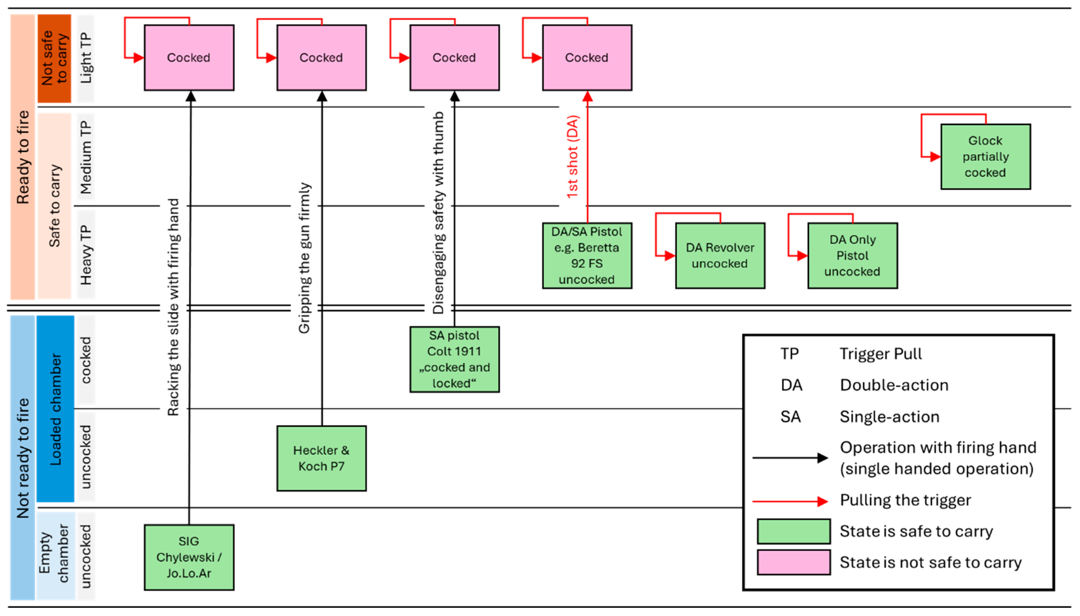
Figure 2.
The two counteracting springs in the Glock’s trigger system: the striker spring and the trigger spring (CAD Screenshot: Matt Rittman).
Figure 2.
The two counteracting springs in the Glock’s trigger system: the striker spring and the trigger spring (CAD Screenshot: Matt Rittman).
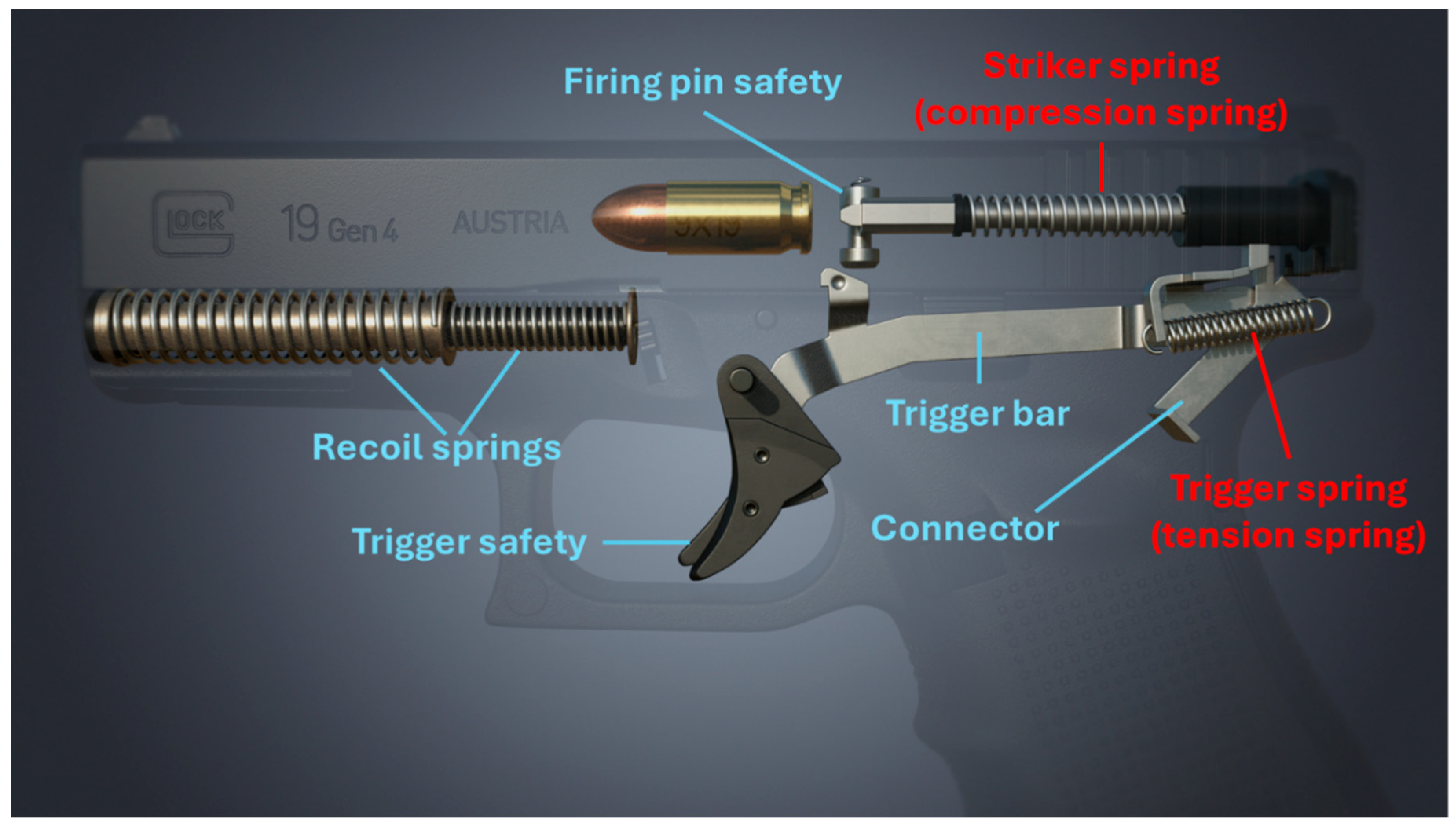
Figure 3.
Cascade from usability contradiction to technical solution.
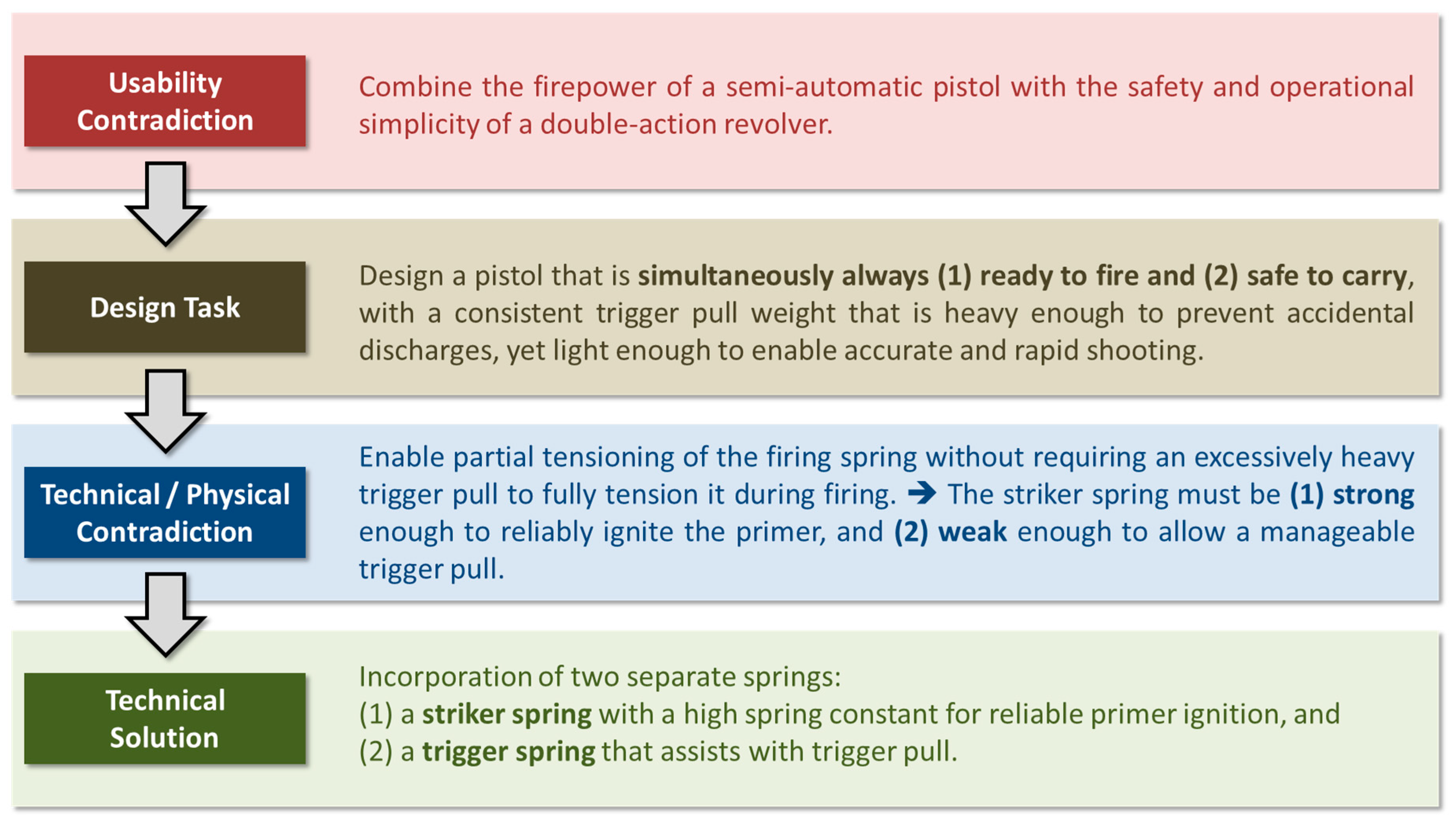
Figure 4.
Comparison of recoil energy storage and energy flow during gun discharge between a double-action/single-action pistol and the Glock pistol.
Figure 4.
Comparison of recoil energy storage and energy flow during gun discharge between a double-action/single-action pistol and the Glock pistol.
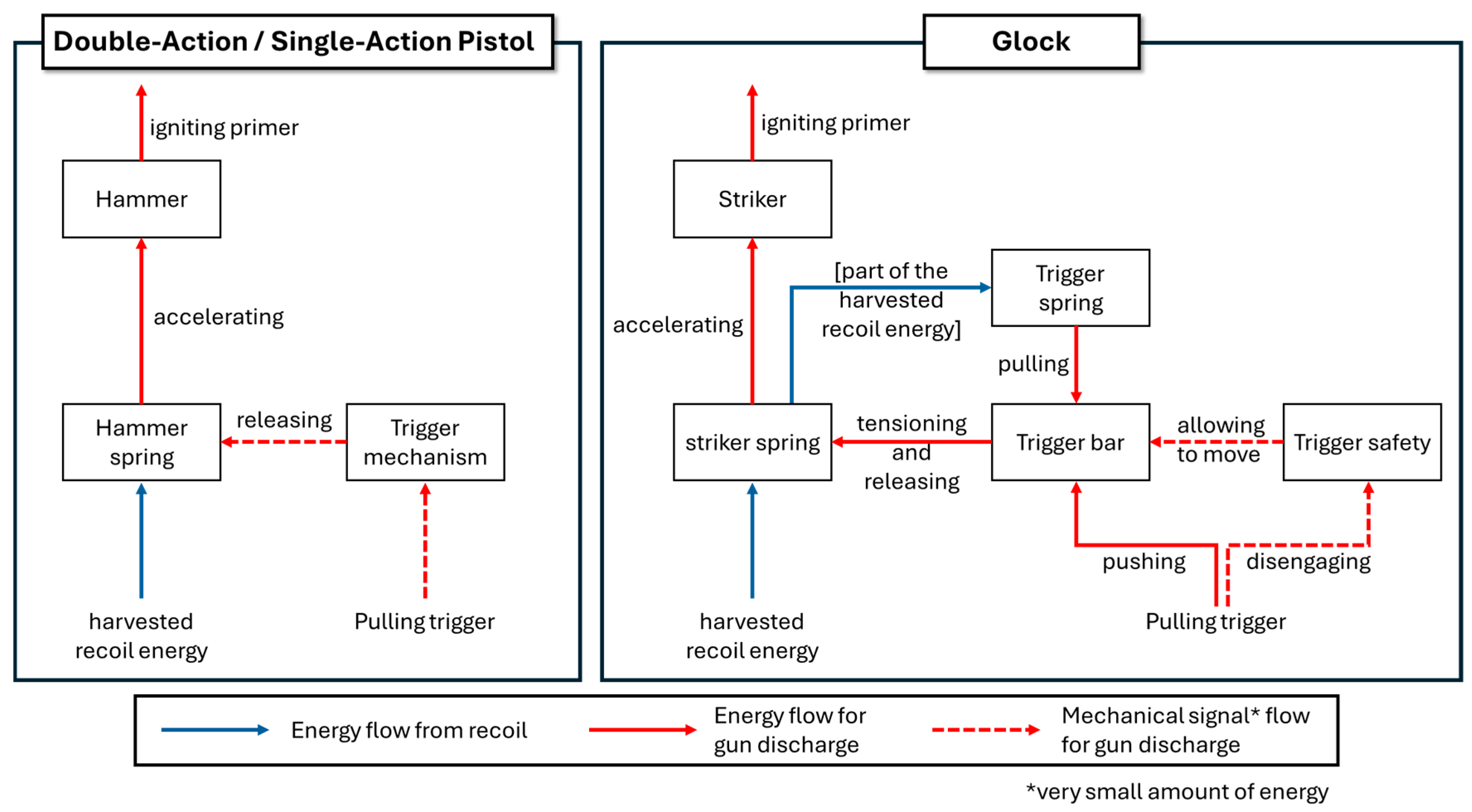
Figure 5.
Trigger mechanism of the Glock pistol (CAD Screenshot: Matt Rittman).
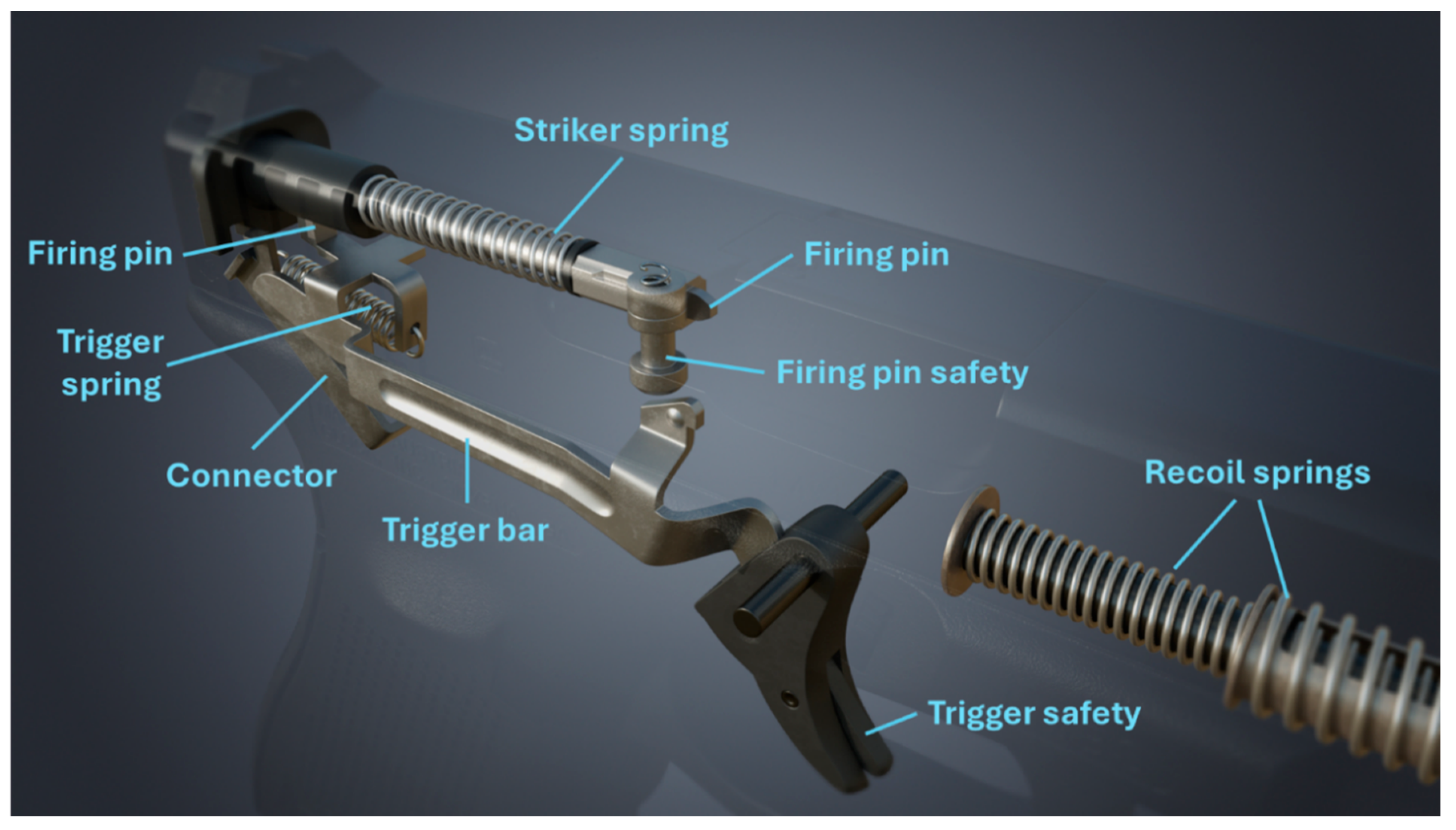
Figure 6.
Side view of the trigger mechanism, including chamber, magazine and locking block (CAD Screenshots from [43]).
Figure 6.
Side view of the trigger mechanism, including chamber, magazine and locking block (CAD Screenshots from [43]).
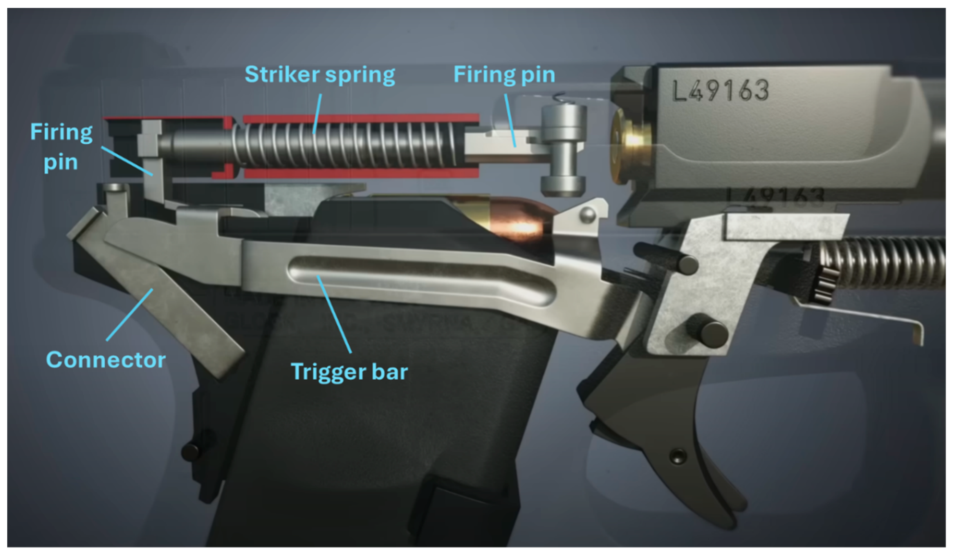
Figure 7.
Drop/Jar safety (CAD Screenshots from [43]).
Figure 7.
Drop/Jar safety (CAD Screenshots from [43]).
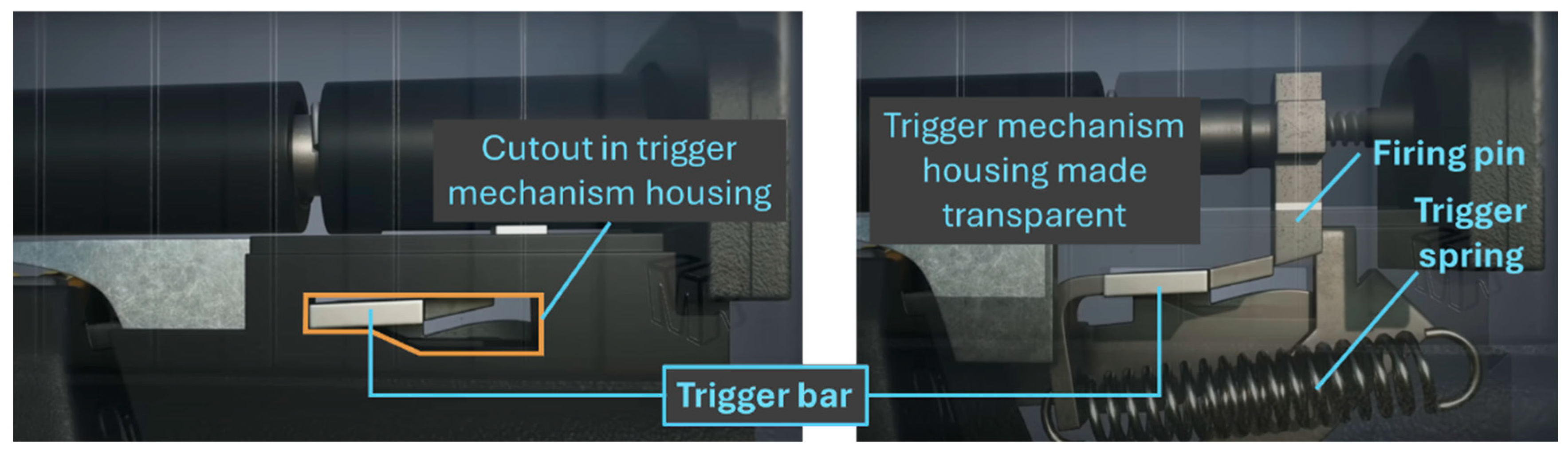
Figure 8.
Trigger safety (CAD Screenshots from [43]).
Figure 8.
Trigger safety (CAD Screenshots from [43]).
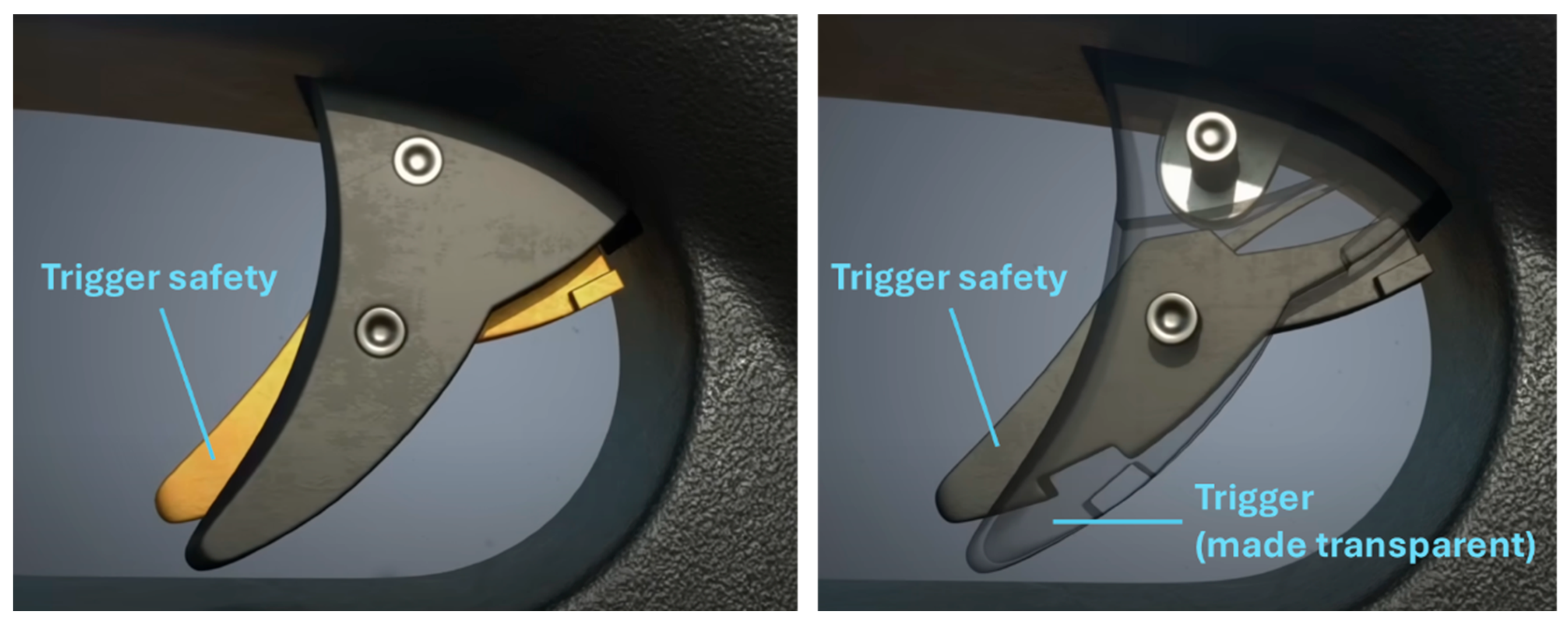
Figure 9.
Firing pin safety (CAD Screenshots from [43]).
Figure 9.
Firing pin safety (CAD Screenshots from [43]).
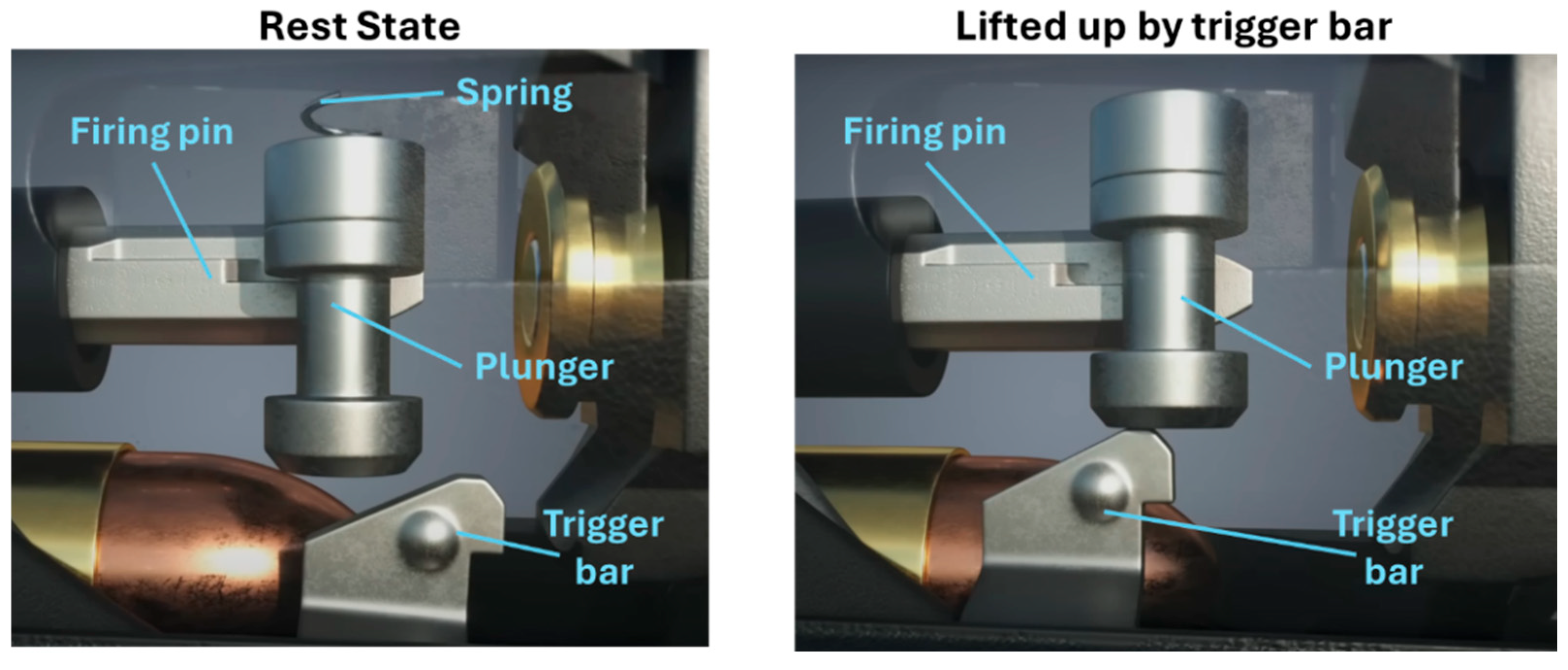
Figure 10.
Trigger bar engaging cam surface of connector at the end of the trigger pull (CAD Screenshots from [43]).
Figure 10.
Trigger bar engaging cam surface of connector at the end of the trigger pull (CAD Screenshots from [43]).
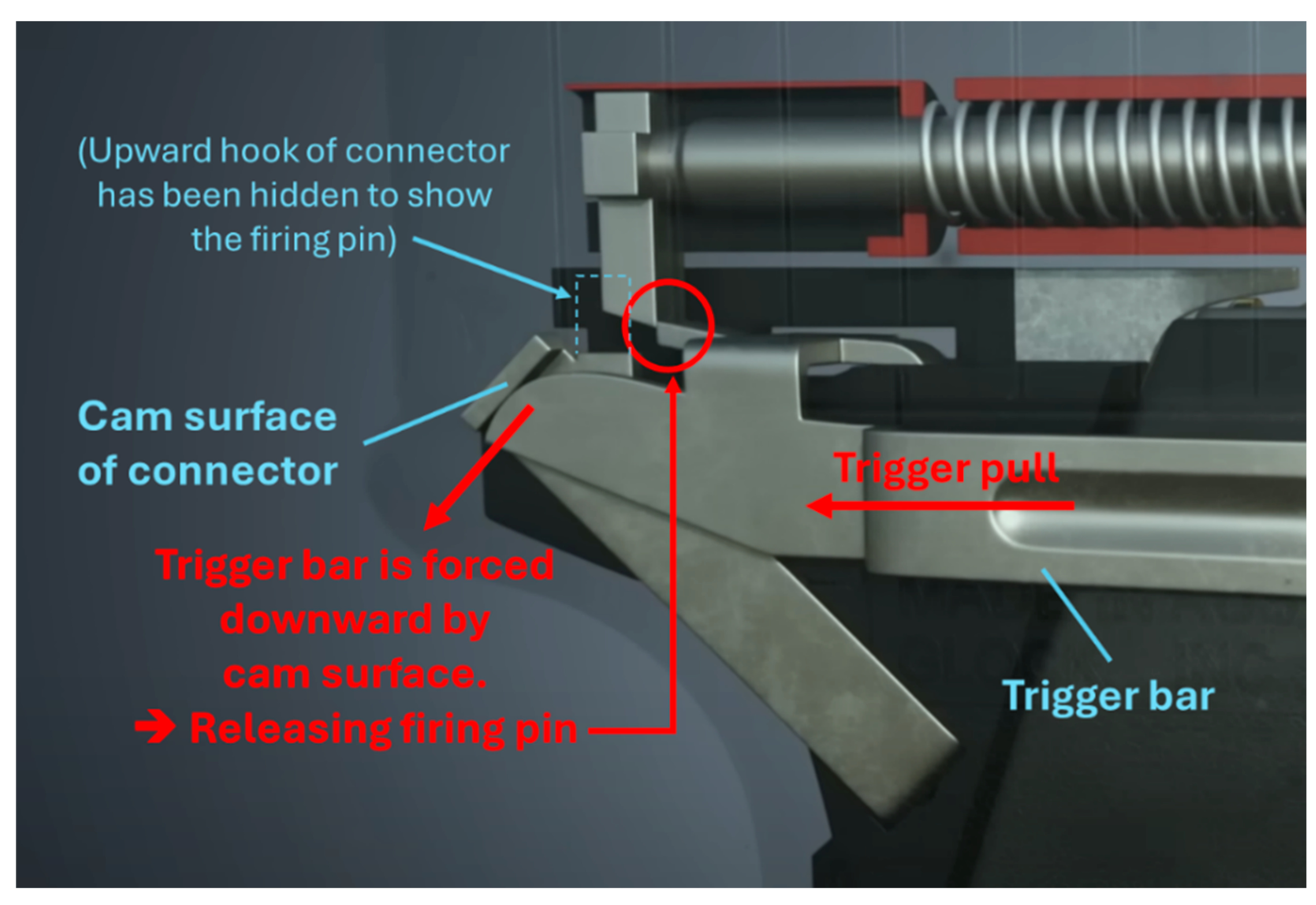
Figure 11.
Disconnector function through the interplay of slide, connector and trigger bar (CAD Screenshots from Rittman (2020)).
Figure 11.
Disconnector function through the interplay of slide, connector and trigger bar (CAD Screenshots from Rittman (2020)).
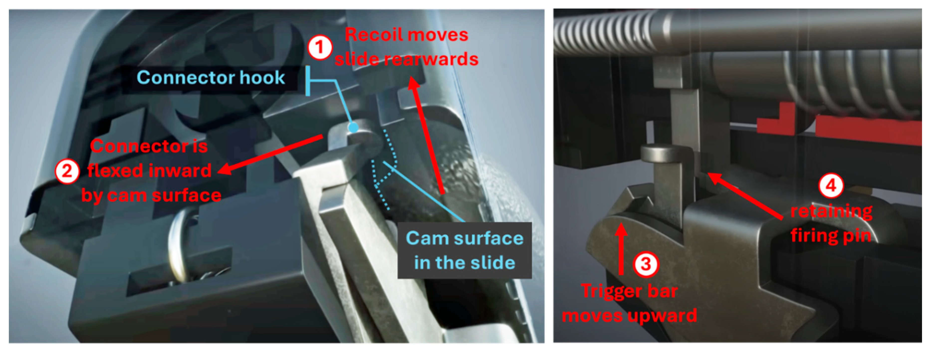
Figure 12.
System state diagram for Glock and double-action/single-action pistols, depicting operational steps required for transition from initial state to intended carry state and the state after firing a shot.
Figure 12.
System state diagram for Glock and double-action/single-action pistols, depicting operational steps required for transition from initial state to intended carry state and the state after firing a shot.
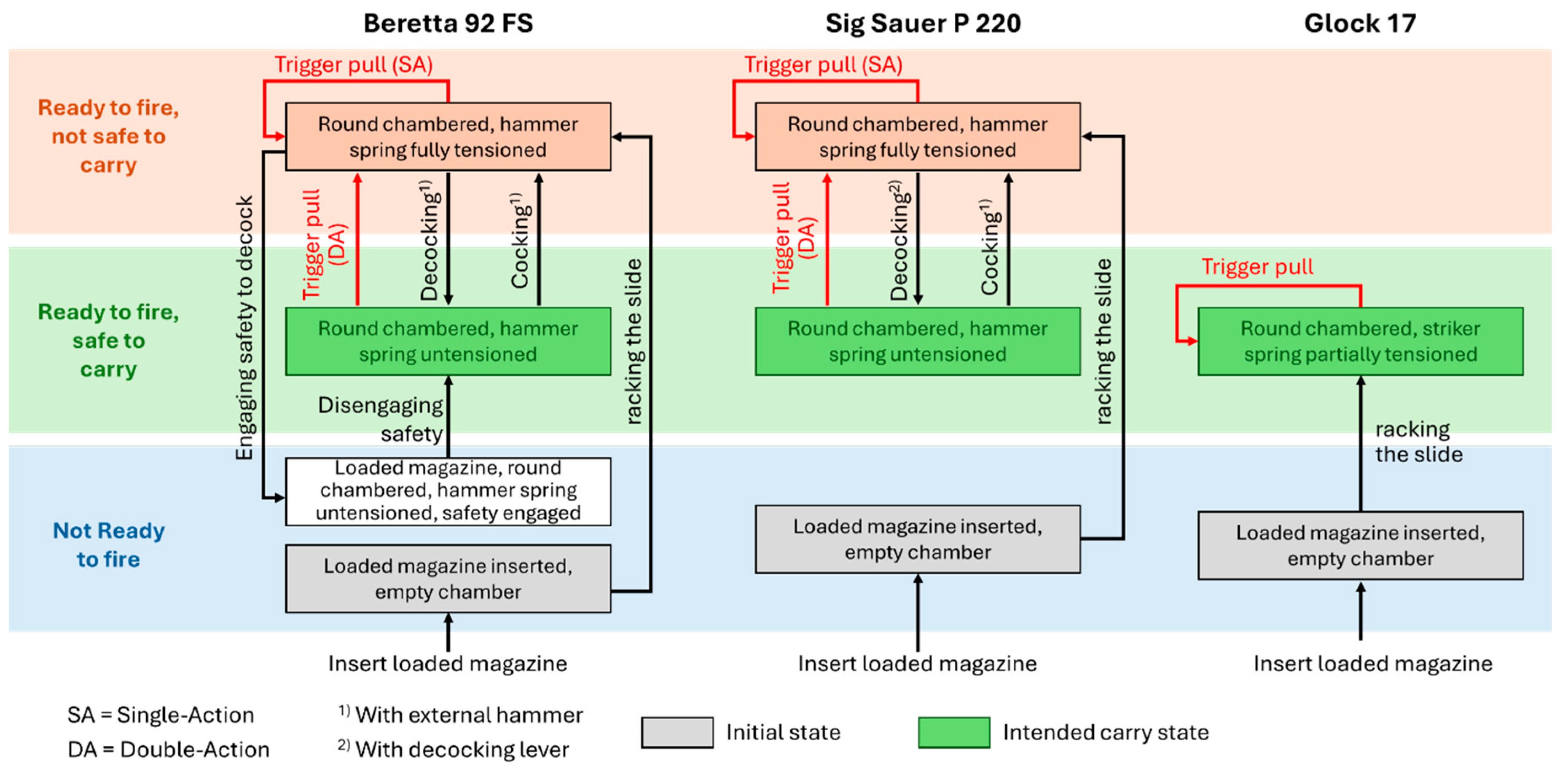
Figure 13.
The Glock’s line of descent.
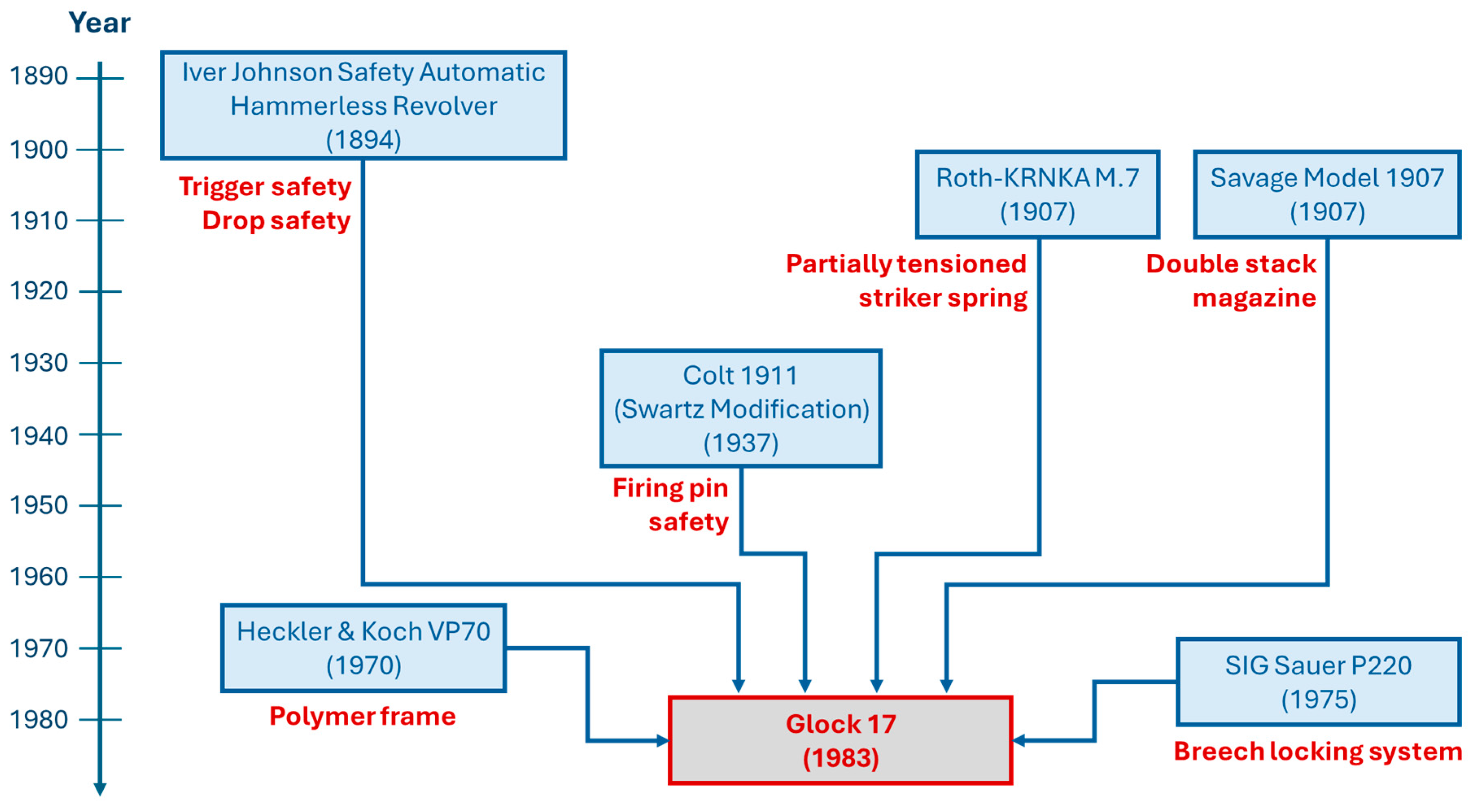
Figure 14.
Polymer frame of the Glock 17 Gen 4.
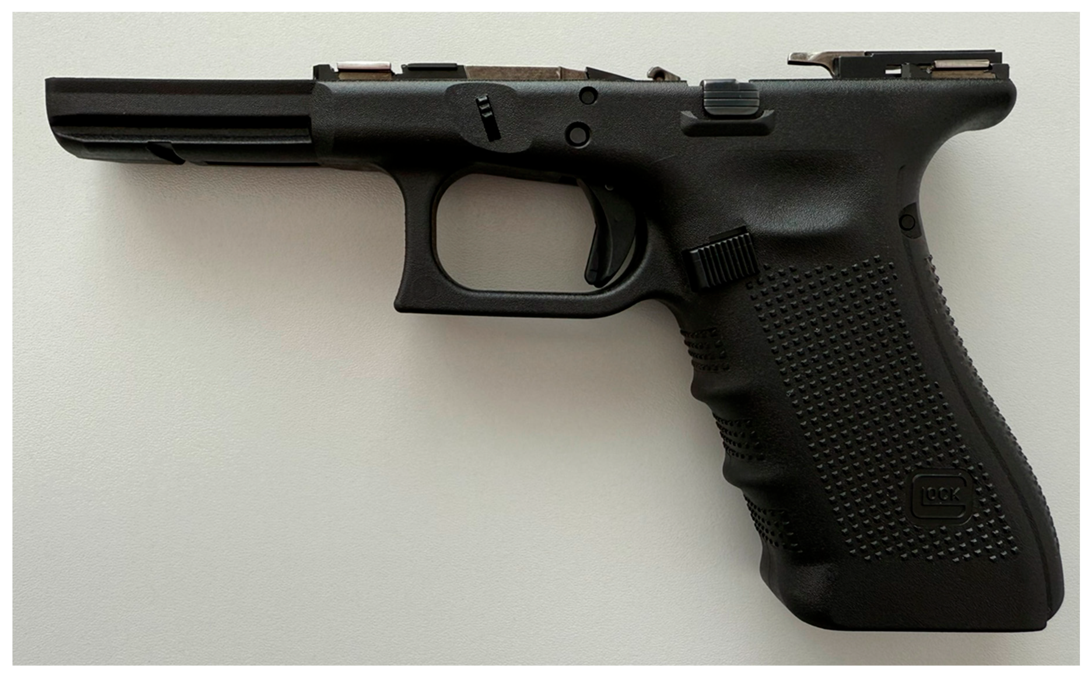
Figure 15.
Slide and barrel of the Glock 17 Gen 4.
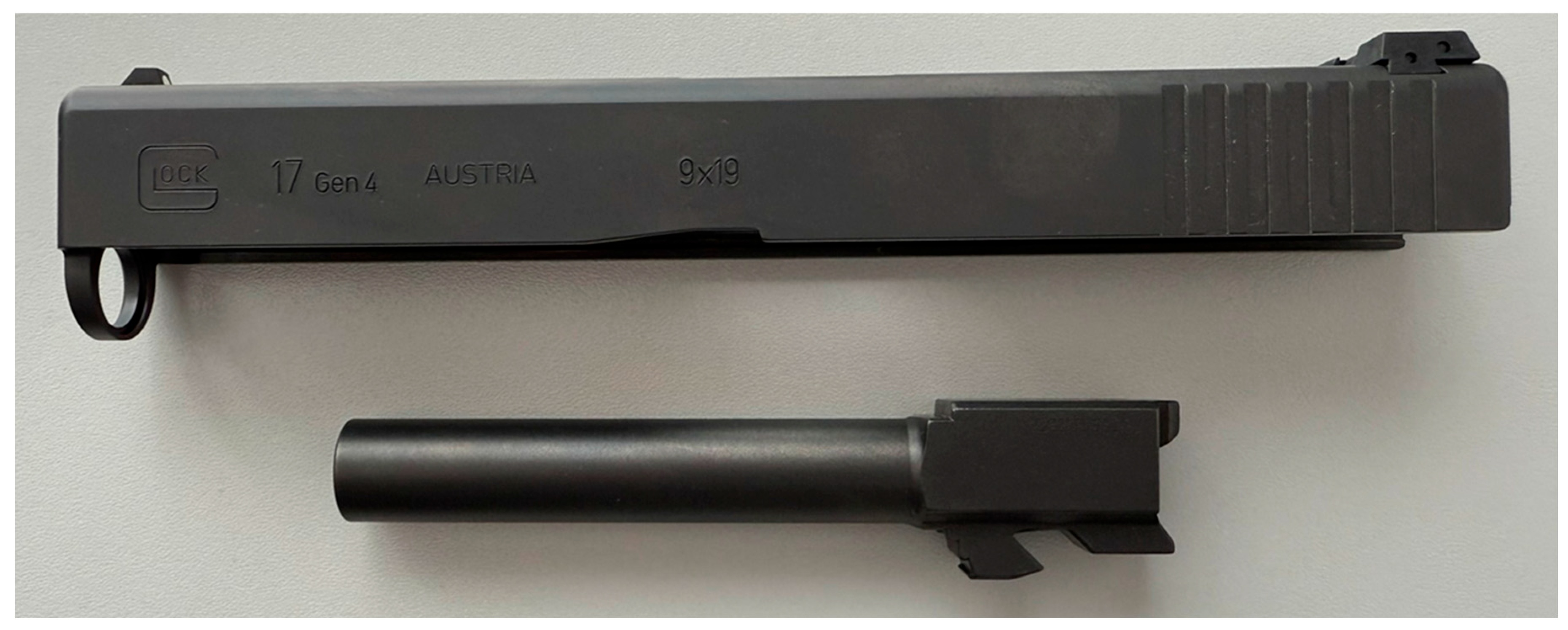
Figure 16.
The Glock 17 Gen 4.
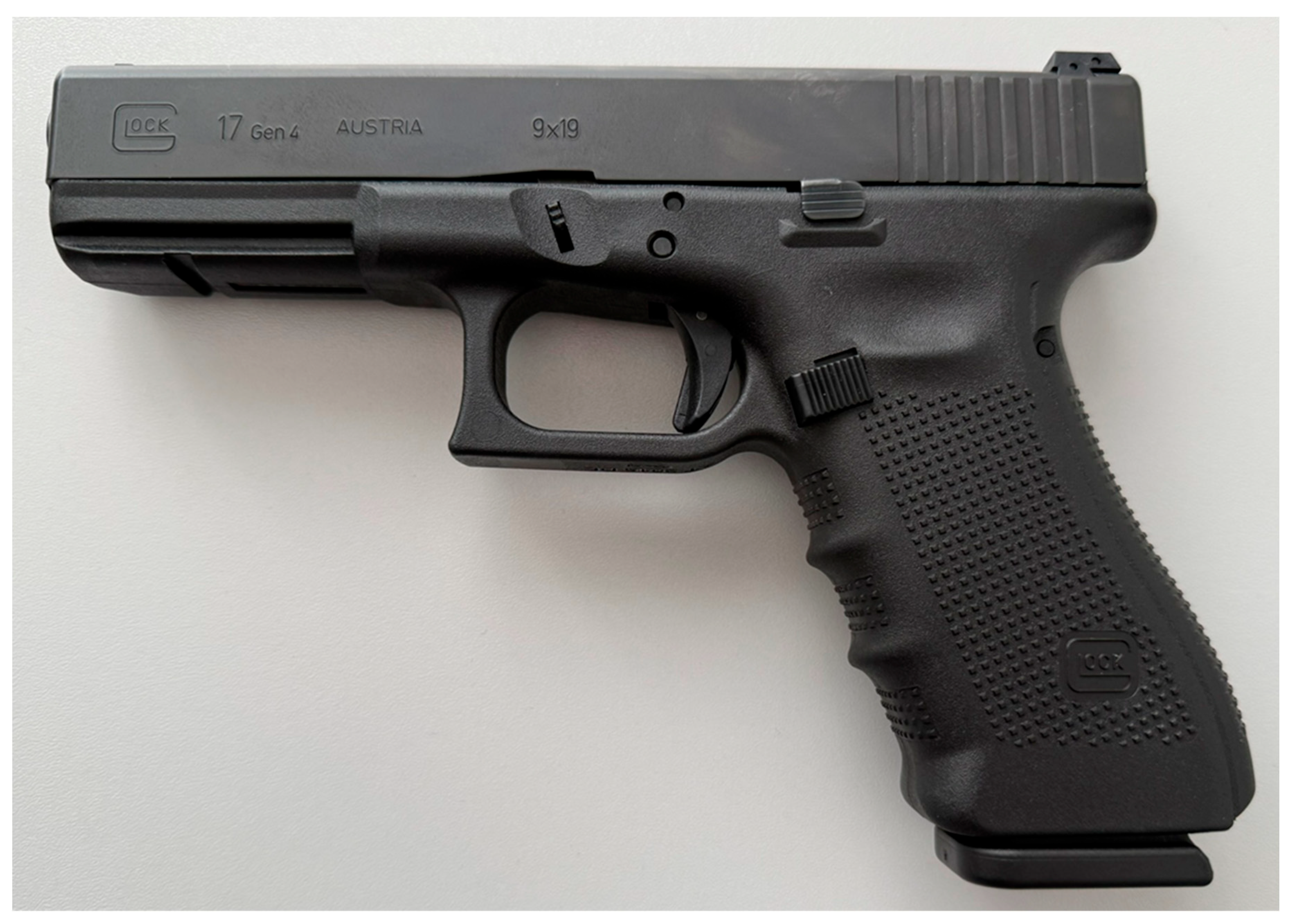
Figure 17.
Left side: First patent listing Gaston Glock as co-inventor (Glock and Kovarik, 1953); right side: Patent of the Field Knife (Glock, 1977b).
Figure 17.
Left side: First patent listing Gaston Glock as co-inventor (Glock and Kovarik, 1953); right side: Patent of the Field Knife (Glock, 1977b).
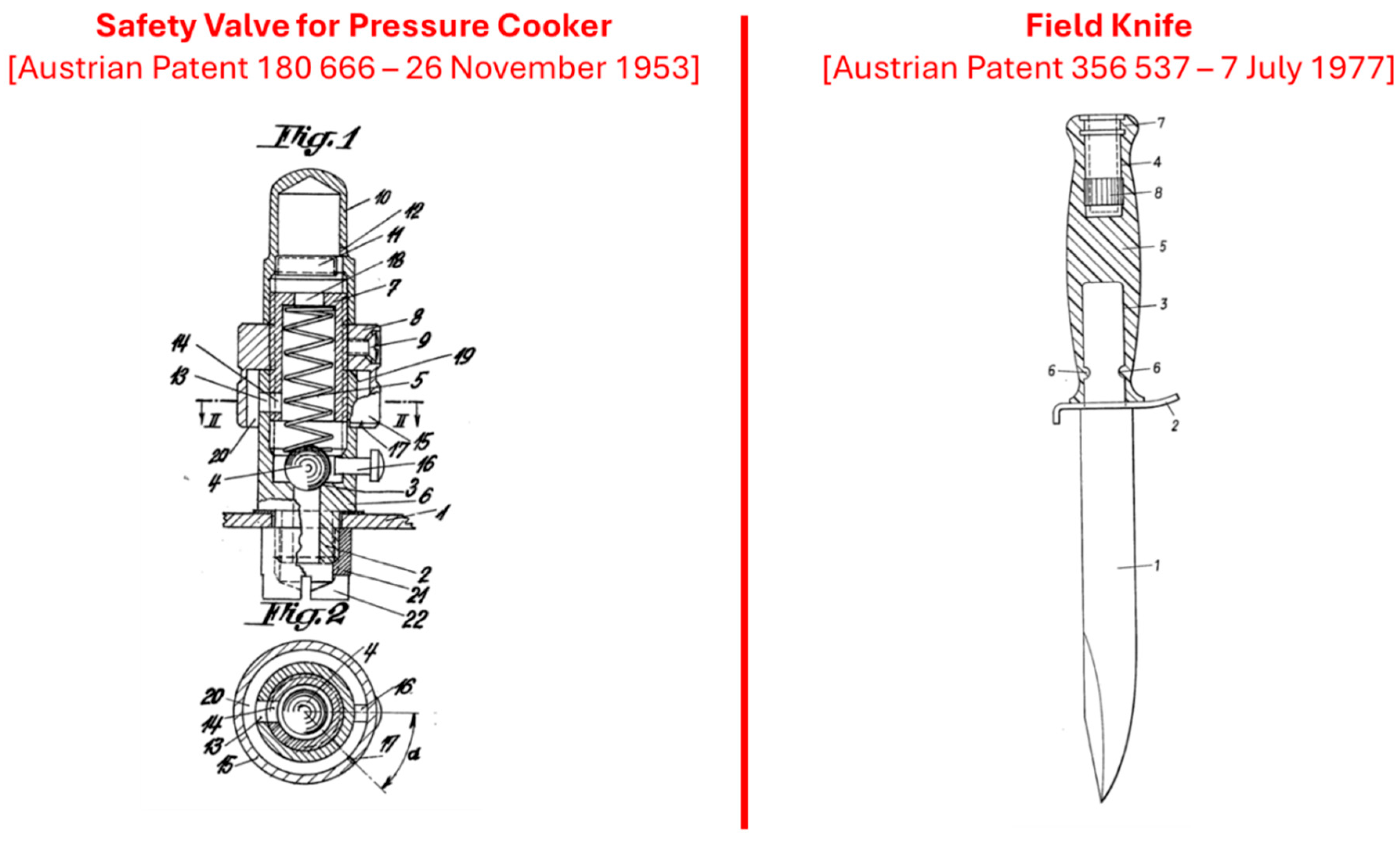
Figure 18.
Dual control loop system of verification and validation in agile product development [52].
Figure 18.
Dual control loop system of verification and validation in agile product development [52].
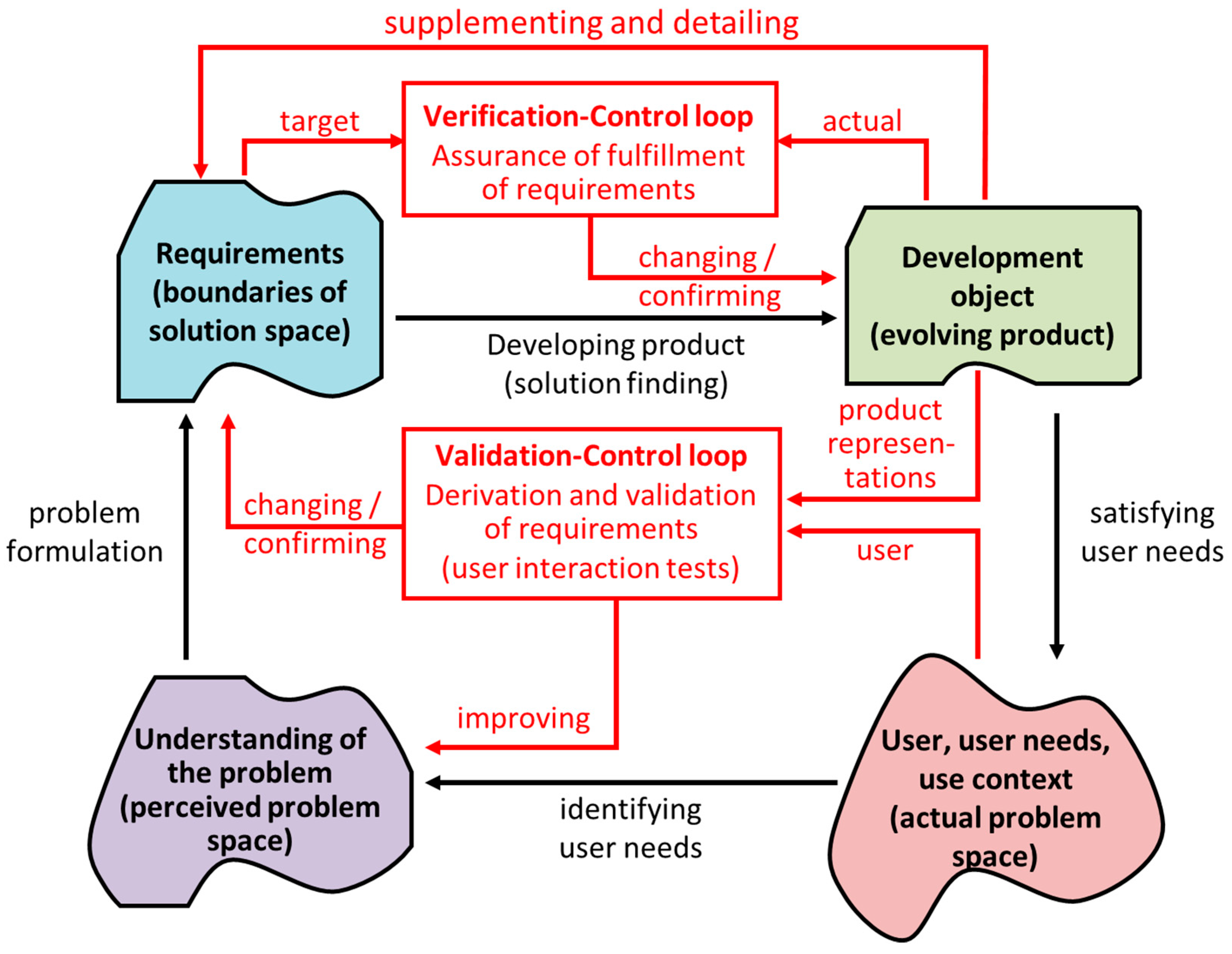
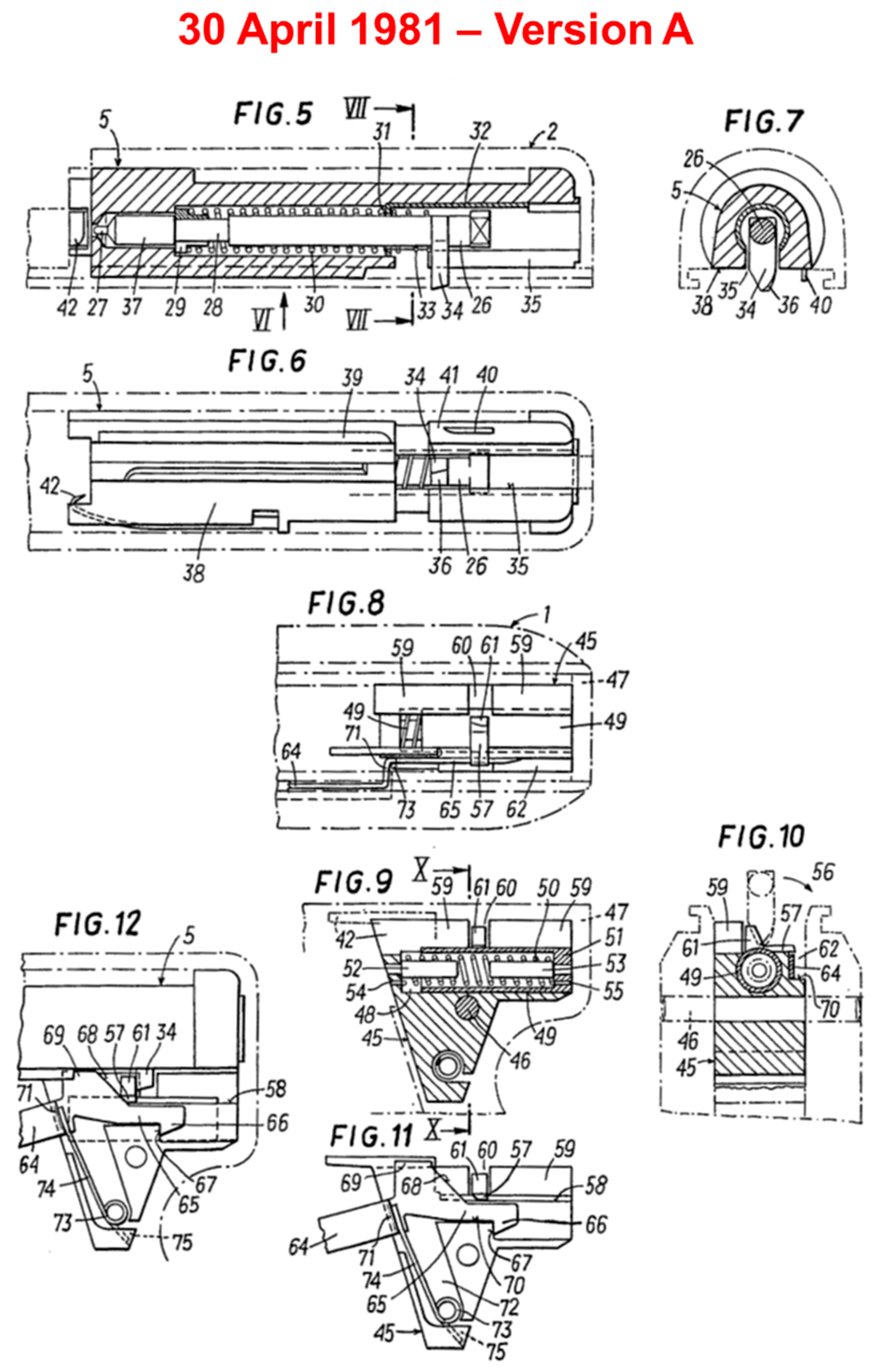
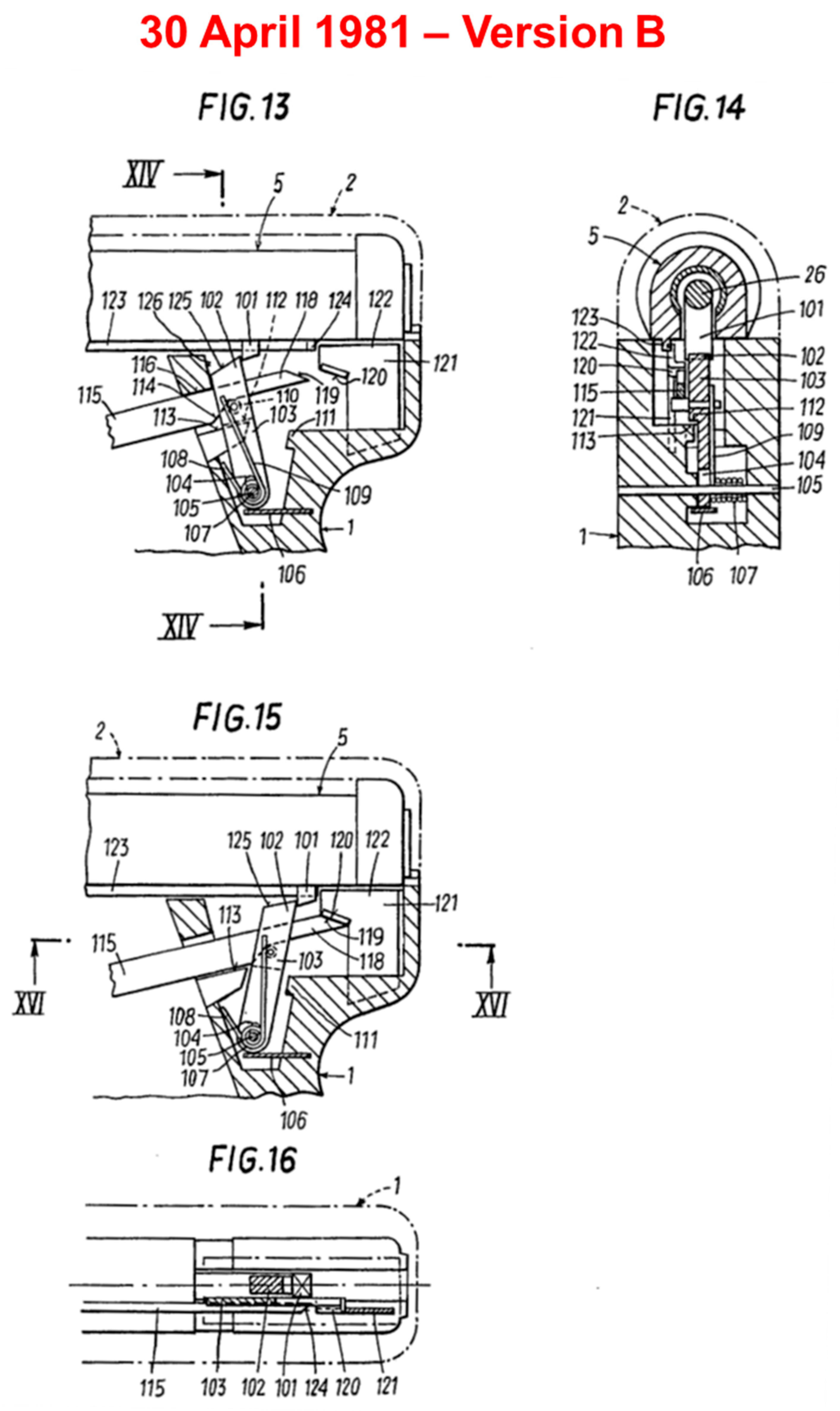
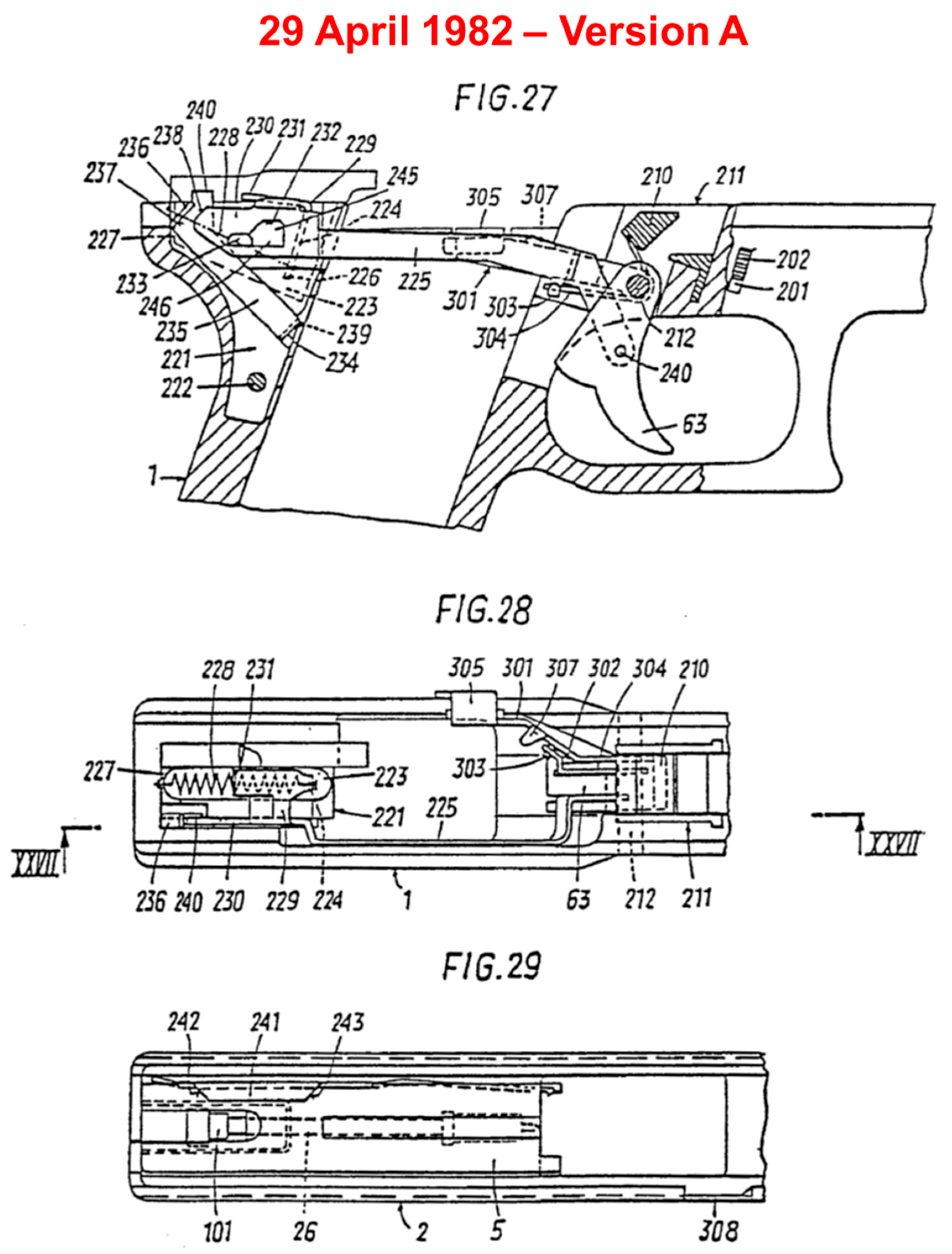
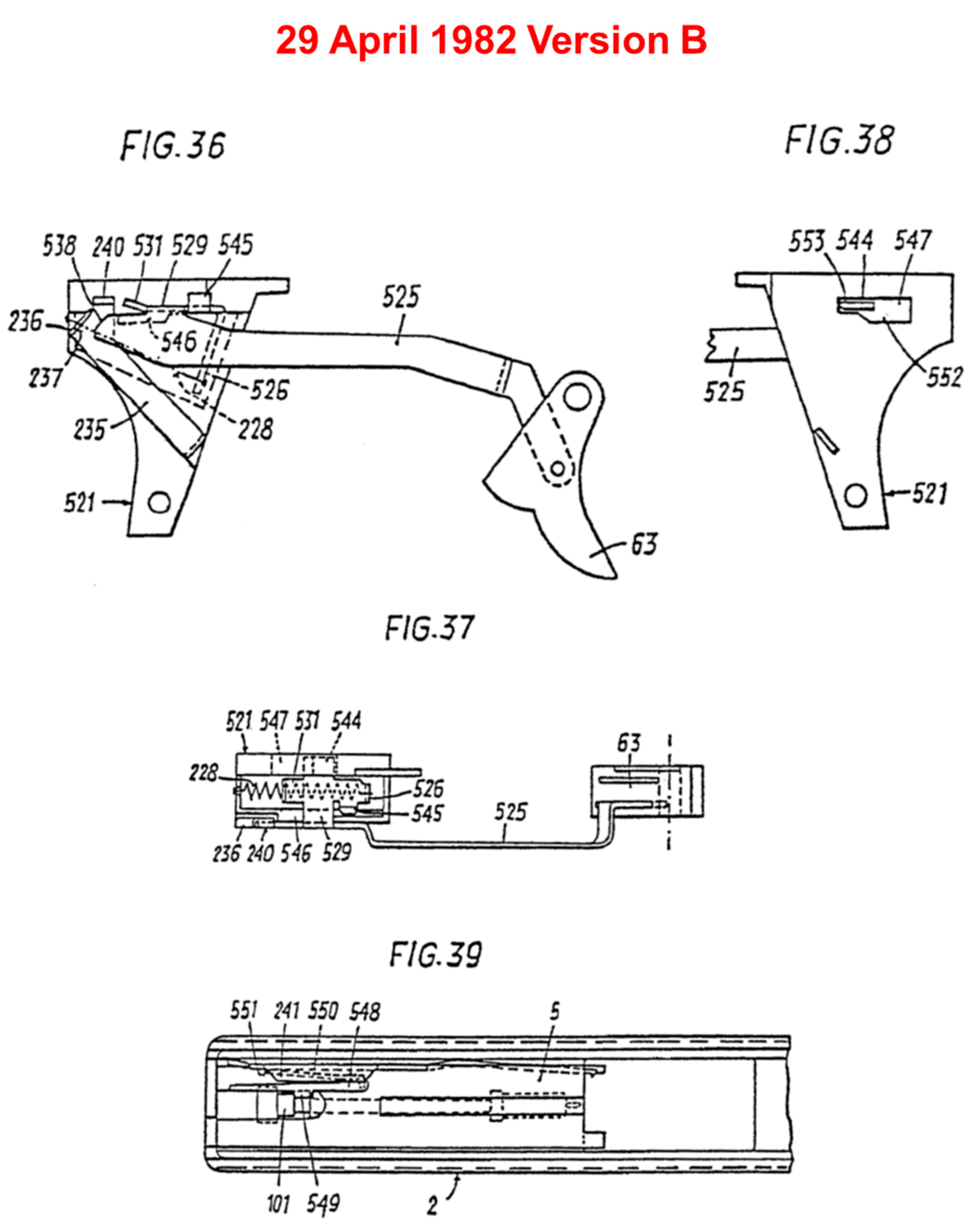
Figure 23.
3rd stage of patenting from 8 April 1983 [59].
Figure 23.
3rd stage of patenting from 8 April 1983 [59].
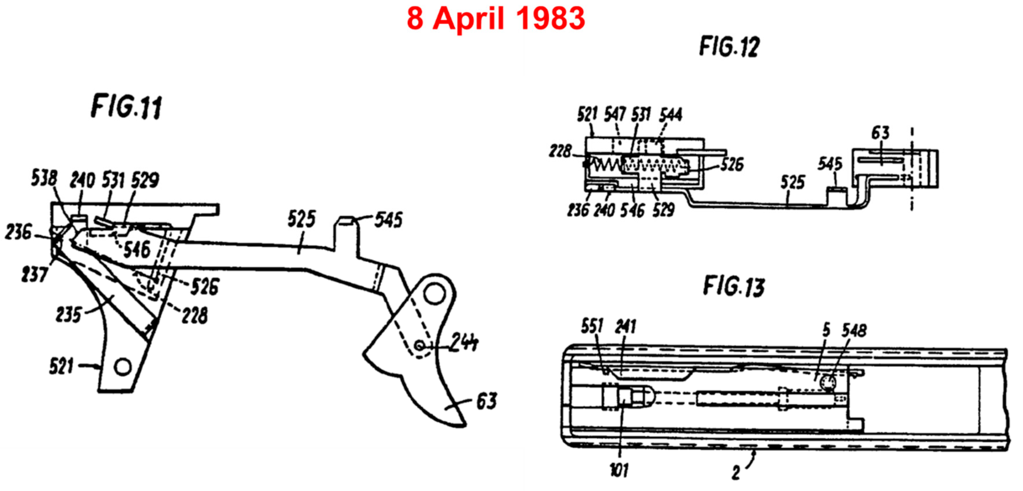
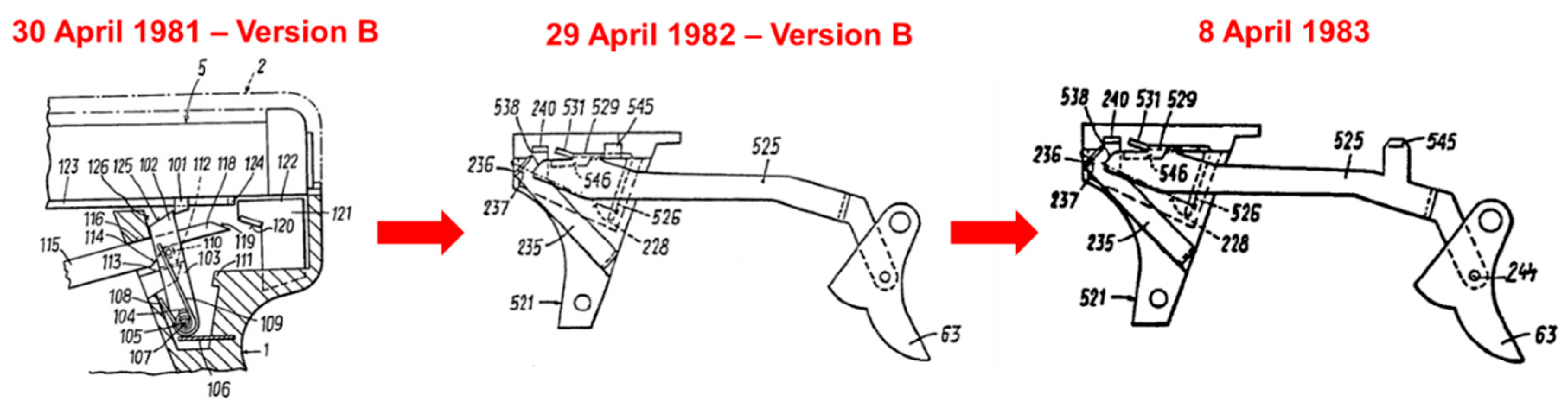
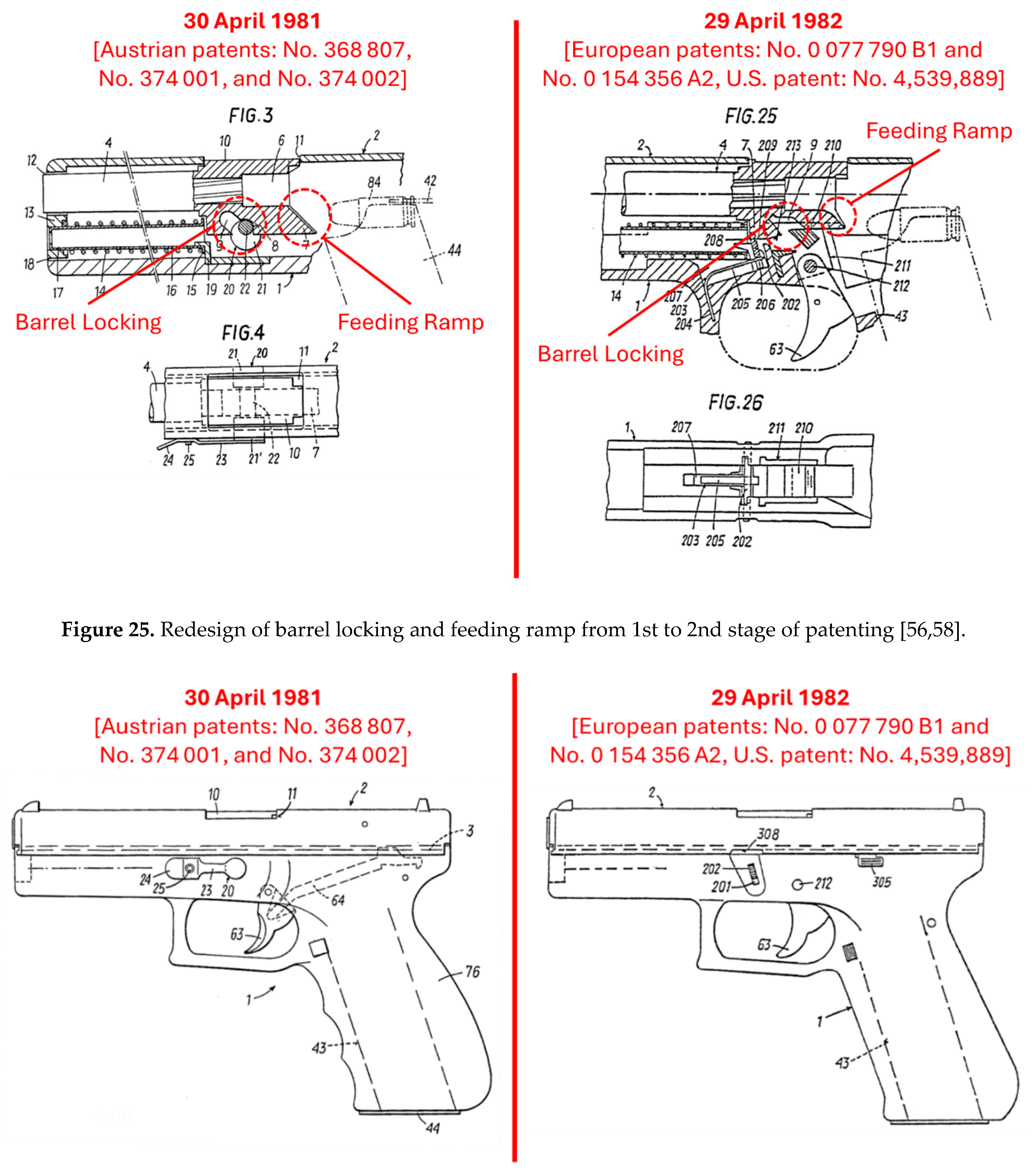
Figure 26.
Redesign of slide lock for disassembly from 1st to 2nd stage of patenting and introduction of a slide stop in 1982 [56,58].
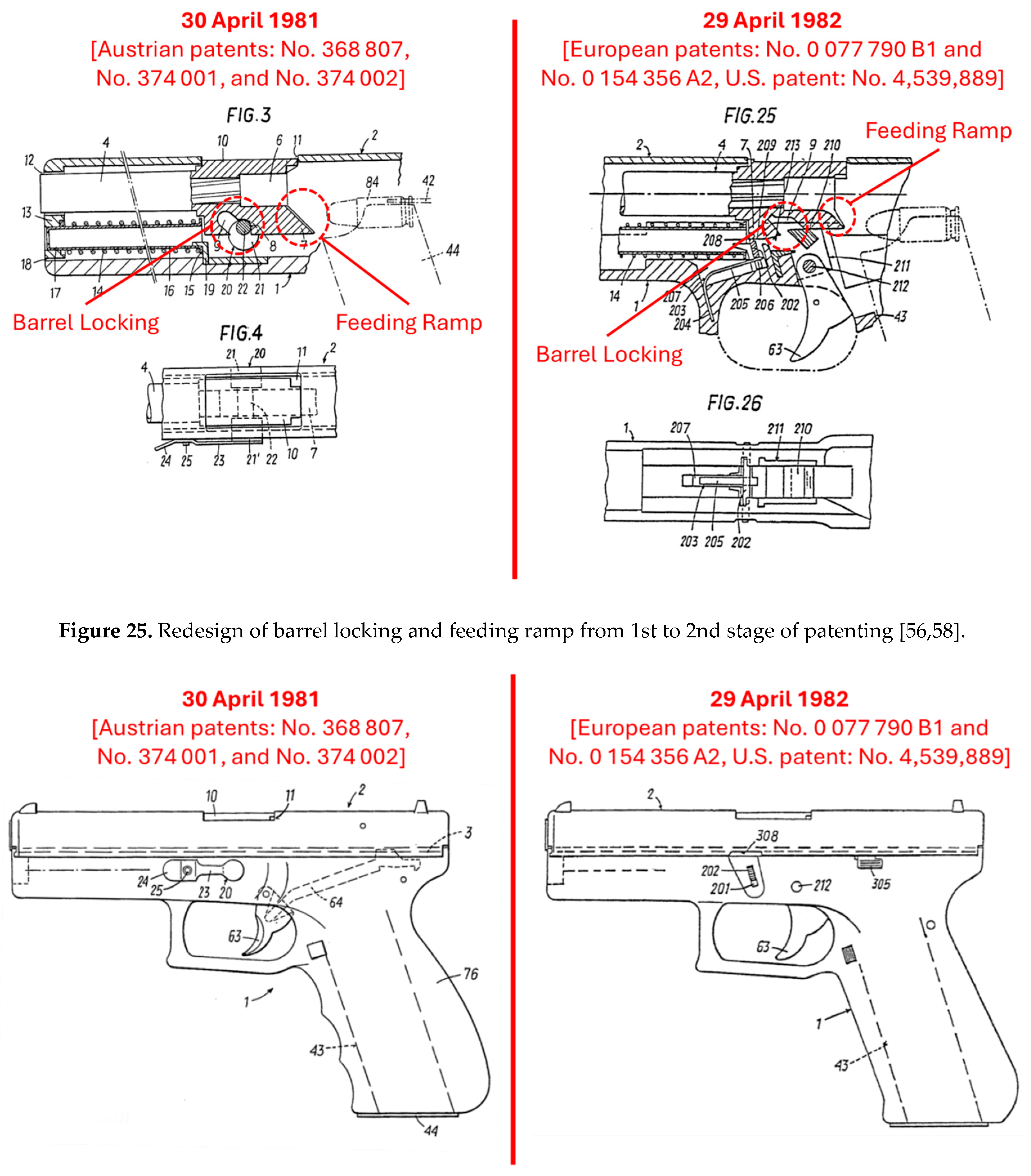
Figure 27.
Human-product interaction system and usability aspects.
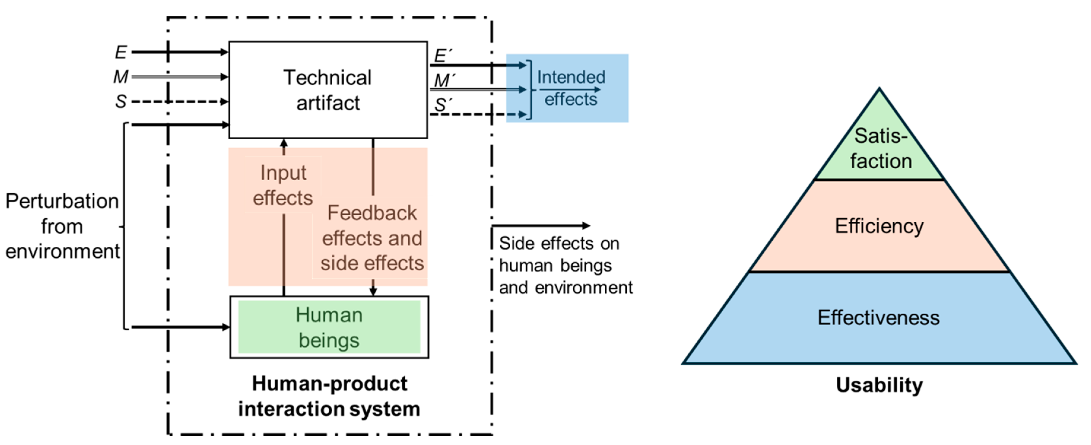
Figure 28.
Model for the evolution of physical products.
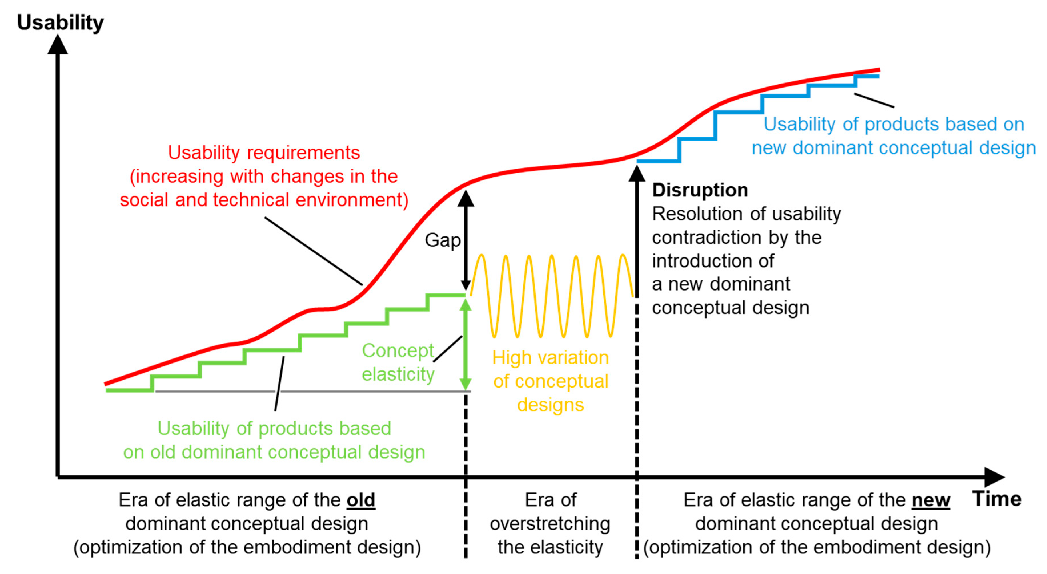
Figure 29.
The interaction of relevant entities in the process of product innovation.
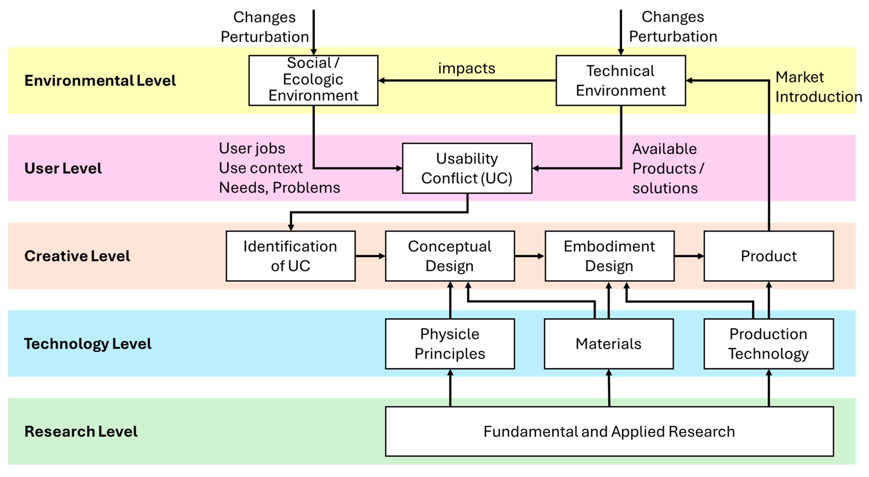
Figure 30.
Crucial interpretative process in product innovation.
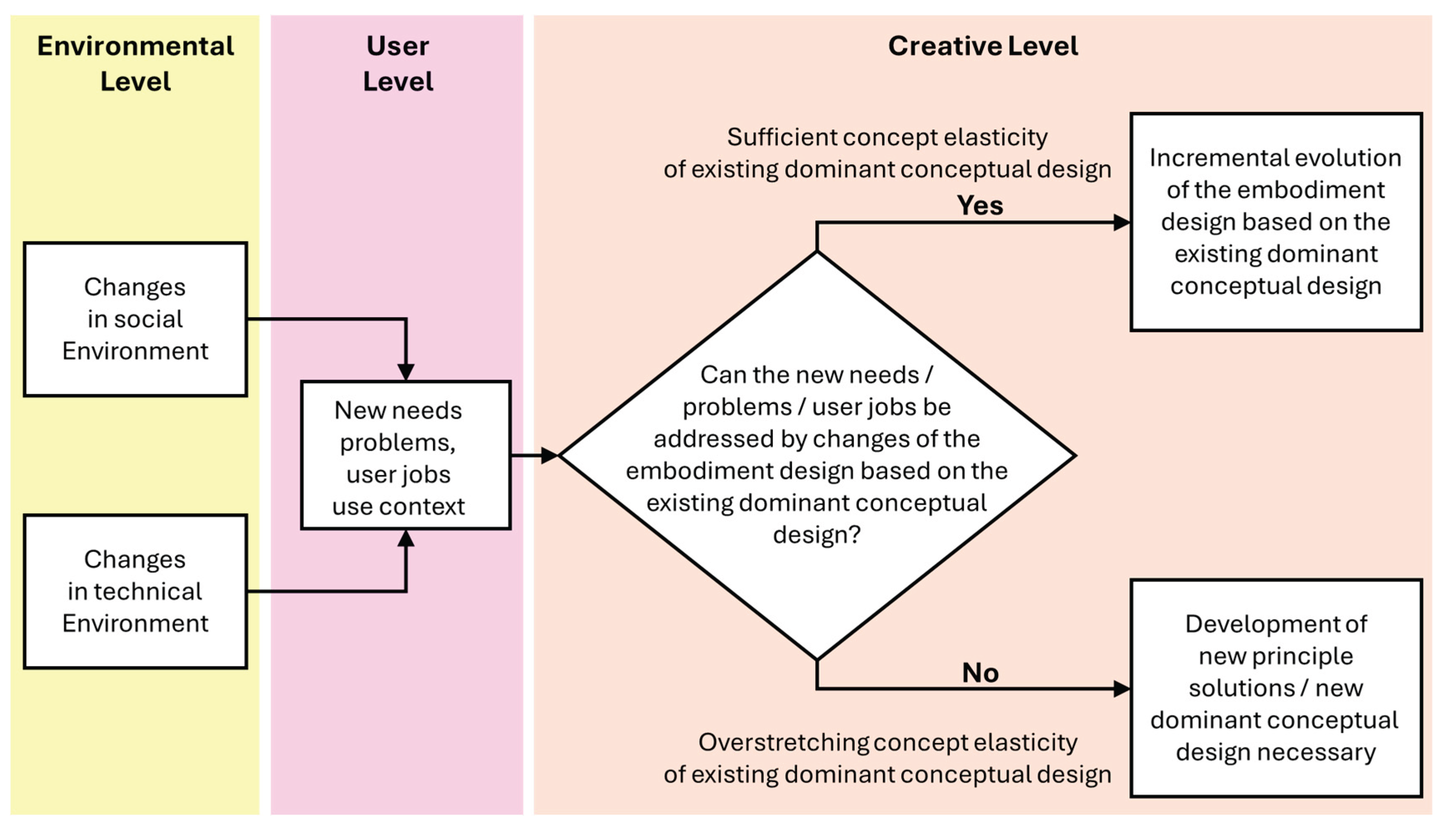
Disclaimer/Publisher’s Note: The statements, opinions and data contained in all publications are solely those of the individual author(s) and contributor(s) and not of MDPI and/or the editor(s). MDPI and/or the editor(s) disclaim responsibility for any injury to people or property resulting from any ideas, methods, instructions or products referred to in the content. |
© 2025 by the authors. Licensee MDPI, Basel, Switzerland. This article is an open access article distributed under the terms and conditions of the Creative Commons Attribution (CC BY) license (http://creativecommons.org/licenses/by/4.0/).
Copyright: This open access article is published under a Creative Commons CC BY 4.0 license, which permit the free download, distribution, and reuse, provided that the author and preprint are cited in any reuse.


