Submitted:
15 May 2025
Posted:
16 May 2025
You are already at the latest version
Abstract
This study presents a systematic review of fatigue analysis methodologies and failure criteria for asphalt binders and mixtures employed in various cyclic fatigue testing configurations. The investigation focuses on three principal predictive approaches: phenomenological models, mechanistic frameworks, and artificial neural network implementations, which are commonly utilized to forecast asphalt pavement fatigue life based on experimental data from different fatigue tests. A critical evaluation is conducted on the diverse failure criteria integrated within these analytical approaches, with particular emphasis on their respective merits and limitations. Current research findings reveal a notable absence of consensus regarding the precise definition of fatigue failure criteria for asphalt materials. Furthermore, critical parameters including accuracy assessment, reliability verification, and sensitivity analysis of these failure criteria are identified as requiring enhanced research attention. The review proposes several innovative methodologies and criteria formulations that could potentially advance theoretical understanding in this field. This comprehensive analysis of fatigue failure mechanisms in asphalt composites aims to inform strategic refinements for future research trajectories and enhance durability-oriented pavement design practices.
Keywords:
fatigue test method
; failure criteria
; fatigue approach
; VECD model
; hot mixture asphalt
1. Introduction
Since the 19th century, when fatigue cracks were observed in steel structures-bridge and railroad-in Europe due to cyclic loading, the phenomenon of fatigue has been gained much attention from researchers and researched in various fields. Regarding the fatigue study of hot mix asphalt (HMA), the first work was performed at Nottingham University in the 1950s[1]. Fatigue cracking, whether bottom up or top down, as one of the primary types of distress in asphalt mixtures reflects the incremental damage that over time accumulates into a macro crack because of the pavement’s exposure to daily and seasonal extreme climatological events (i.e. rain, thermal changes, solar radiation, etc) and repeated vehicular loads especially[2,3,4,5,6,7,8,9]. These fatigue cracks occur due to the tensile and compressive strains that develop in reverse directions at the top and bottom of asphalt pavement layers under repeated axle loads. They appear in the form of hexagonal, longitudinal, and alligator cracks on the road surface, which can lead to a decrease in driving quality and fuel economy by increasing the roughness of the road, and provide channels for water intrusion, especially in the wheel paths, causing the rapid deterioration of the pavement system and increasing maintenance costs[10,11,12]. Over the past few decades, the pavement industry has increasingly focused on the fatigue cracking because it is directly related to the service life of the pavement. It must be properly studied to ensure appropriate structural design, especially with the use of new materials such as highly polymerized asphalt binders (HPABs), high modulus asphalt binder (HMAB) and warm mix asphalt (WMA) additives, and the introduction of the reclaimed asphalt pavement.
Although the fatigue performance of asphalt binders and mixtures has been extensively studied by researchers[13,14,15,16,17,18,19,20] in the past few decades, this phenomenon is still not fully understood. Various methods are developed in the laboratory to characterize fatigue of the asphalt mixtures, including phenomenological approach[21,22], mechanistic approach, energy-based approach and artificial neural network approach, etc. Based on the different test methods mentioned above, both domestic and international scholars have conducted extensive research to define numerous fatigue models, aiming to accurately predict the service life of asphalt pavements and guide the actual pavement structural design. However, the focus of the research has been primarily on the development of the models themselves, while the definition of fatigue failure criteria, which plays a crucial role in fatigue performance prediction models, has been overlooked. The fatigue failure criterion directly determines the termination conditions of the fatigue test. When different fatigue failure criteria are applied, the degree of fatigue damage to the material at the end of the test varies, which is one of the reasons for the significant variability in the fatigue life of asphalt mixtures[23]. Also, different fatigue failure criteria can cause different theoretical foundations for predicting the fatigue performance of the mixtures. Wang[24] believes that scientifically sound laboratory testing methods, effective data analysis techniques, and the material's own fatigue failure criteria are the three fundamental components for evaluating and predicting the fatigue performance of asphalt materials. An accurate, standardized, and consistent definition of failure is needed to maintain the integrity of test results and provide a consistent basis for any implementation scheme[7]. Hence, the definition of fatigue failure criterion in the laboratory is an important issue.
However, there is currently no consensus on the definition of fatigue failure criteria of asphalt binders and mixtures in the academic community. Typically, the failure criteria are used to determine when a material fails, that is, the number of cycles corresponding to the failure with independent on the load modes, test temperatures, and strain amplitudes. It is closely related to the critical stages of the fatigue testing process and the fatigue life prediction model itself. Gudipudi and Underwood[2] divided failure criteria into experimental failure criteria and model failure criteria, which are referred to as the failure indicator and failure criterion in other literature examples[25], respectively. For example, the failure criterion in AASHTO TP 107-18[26], namely the relationship between GR versus Nf, is considered a model failure criterion. In contrast, the conventional failure criterion[27] where the modulus value decreases to 50% of its initial value is considered an experimental failure criterion.
As previously detailed, the determination of fatigue failure criteria is closely related to the fatigue testing methods and life prediction models for asphalt binders and mixtures. Therefore, the objective of this work is to systematically elaborate on the fatigue testing methods and to summarize the failure criteria based on these methods and the established life prediction models. This contributes to improving the accuracy and reliability of pavement performance predictions and assist in refining or redefining failure criteria for future research, thereby guiding the durability design of asphalt pavements in the field.
2. Fatigue Test Methods
The fatigue life of HMA is measured by conducting fatigue tests at various initial strain/stress levels in the laboratory. The field fatigue performance prediction of asphalt pavements is achieved by processing laboratory test results with shift factors, as these factors take into account influential long-term parameters such as aging, healing, traffic load, temperature variations, sunlight effects, and moisture damage. The shift factor can be 15 to 20 times the fatigue life estimates derived from laboratory results[7]. In order to evaluate the fatigue life of HMA, different types of tests with different specific protocol have been reported in the literature over the past decades. These tests are classified based on two criteria, loading mode and stress-strain distribution. Regarding loading mode, fatigue tests are divided into three groups: (1) simple flexure, (2) direct uniaxial, and (3) diametral load tests. Regarding stress-strain distribution, fatigue tests are categorized into two types: (1) homogenous and (2) non-homogenous[7].
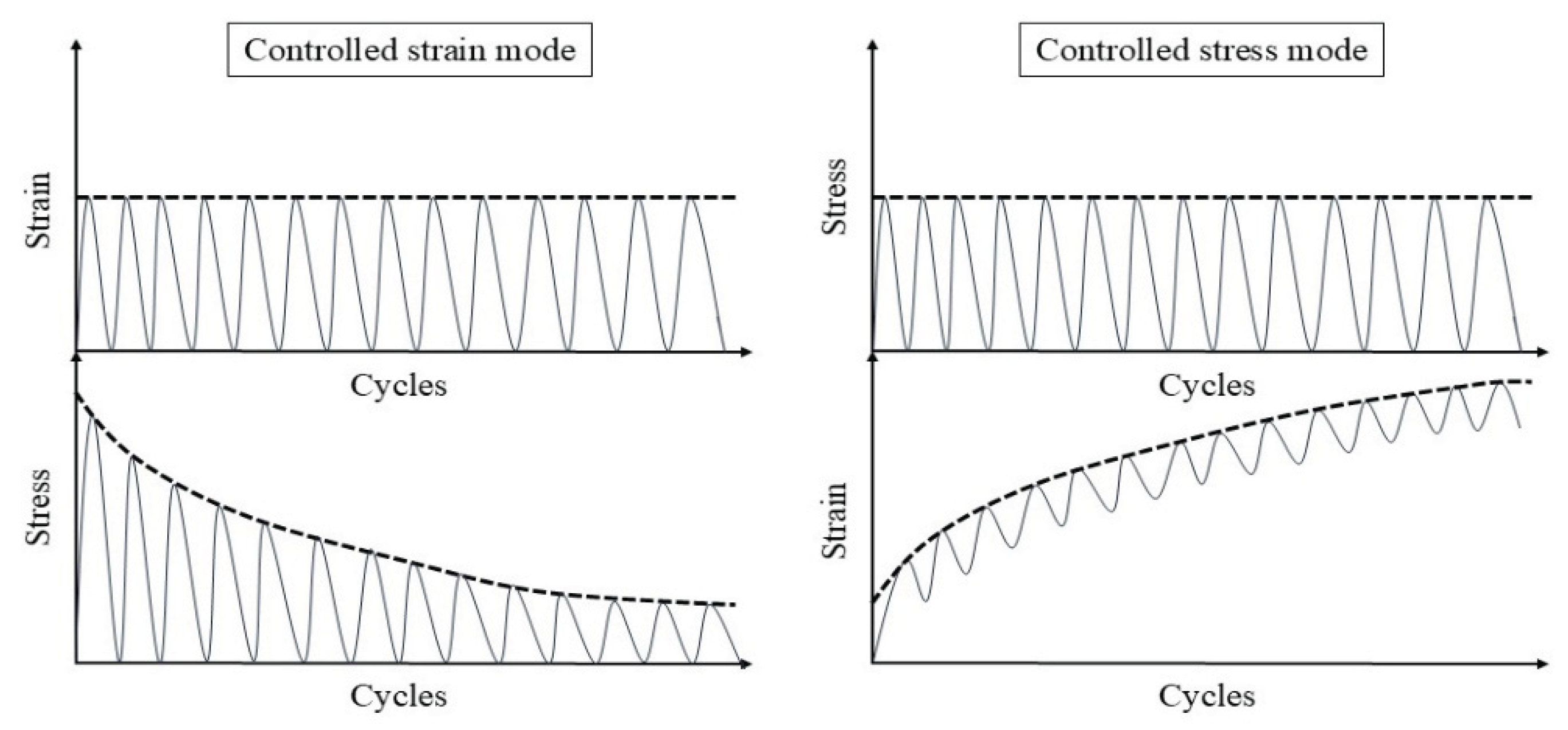
The fatigue tests are susceptible to the modes and loading waveforms in the laboratory. There are four test modes used for hot mix asphalt fatigue testing: controlled stress (load) mode, controlled strain (displacement) mode, controlled energy mode[28,29], and combined modes[30]. The first two are the most common and widely used by researchers, whereas the latter two are less commonly applied. For the same type of asphalt mixture, under similar initial fatigue test conditions, the fatigue life in stress-controlled mode is significantly shorter than in strain-controlled mode. This is because, in the stress-controlled mode, the peak and valley values of stress on the specimen remain constant. As the number of load cycles increases, the strain on the specimen gradually increases, ultimately leading to fracture and failure of the specimen. In contrast, in the strain-controlled mode, the peak and valley values of strain at the bottom of the specimen remain constant. As the number of load cycles increases, the stress on the specimen gradually decreases, as shown in Figure 1 below. Therefore, in strain-controlled mode, the specimen does not exhibit noticeable cracking by the end of the test. For the same type of HMA under the same initial conditions, the fatigue life in strain-controlled mode is longer than in stress-controlled mode, approximately 2 to 3 times longer[31,32]. The loading waveforms in fatigue cyclic tests include sinusoidal waveform[33] and haversine waveform[34,35] (). As shown in Figure 2, the main difference between the sinusoidal waveform and the haversine waveform is that the former has stress, strain, or deflection in two directions, which can only cause fatigue damage in beam specimens. In contrast, the latter waveform has only one direction, and in cyclic loading fatigue tests, it can induce bending deformation in beam specimens, resulting in both permanent deformation and fatigue damage. This is closer to the repeated axle loads experienced by actual road surfaces[36].
Figure 1.
The relationship between stress, strain and cycles under strain and stress controlled modes.
Figure 1.
The relationship between stress, strain and cycles under strain and stress controlled modes.
While the dynamic shear properties of binders are measured using the Dynamic Shear Rheometer (DSR) shown in Figure 3, the DSR remains a primary instrument to evaluate the fatigue performance of the asphalt binders through linear amplitude sweep (LAS) and time sweep (TS)[37]. In addition, an innovative device, the Annular Shear Rheometer (ASR), was developed to investigate the fatigue properties of bitumens and mastics, as shown in Figure 4.
The experimental methods applying to the fatigue damage analysis of asphalt mixtures including fine aggregate matrix (FAM) and asphalt concrete (AC) are summarized in Figure 5 and Figure 6, respectively. In addition, other tests can also be used to evaluate fatigue performance, such as supported flexure test[7], double edge notched test, overlay tester, dogbone tester, loaded wheel tester[38], semi-circular beam (SCB) LTRC method[39,40], semi-circular beam (SCB) I-FIT method[41,42], disk compact tension (DCT)[43,44], single edge notched beam (SENB)[45,46], double edge notched prism (DENP)[47] and UGR-FACT(University of Granada-Fatigue Asphalt Cracking Test) method[9,48]. Different types of tests to evaluate the fatigue life of asphalt binders and asphalt mixtures are summarized in Table 1.
The fatigue test results of asphalt binders and mixtures can be obtained through the aforementioned various fatigue test methods. Fatigue approaches are developed when analyzing fatigue test results, aimed at predicting the fatigue life of asphalt pavements. They are mainly divided into phenomenological approaches, mechanistic approaches, and artificial neural network approaches. Failure criteria are reference points used to define the fatigue performance at a stage or zone where the material's behavior undergoes significant change[7,71]. These criteria directly determine the termination conditions of fatigue tests and the degree of fatigue damage to the material. Failure criteria are closely associated with fatigue approaches and are divided into experimental failure criteria and model failure criteria[2].
Since Heveem[72] discovered the fatigue failure of asphalt pavements and established the relationship between the tensile strain or tensile stress at the bottom of the asphalt layer and the cumulative number of load cycles at the time of pavement cracking, the phenomenological approach, sometimes called the traditional approach or classical approach, has become one of the main research approaches for studying the fatigue damage characteristics and life prediction of asphalt mixtures. In general, the mechanistic approaches include fracture mechanics approach and viscoelastic continuum damage (VECD) approach[1,7,73]. In addition, the viscoelastic fracture mechanics (VEFM) method developed by combining the two concepts in literature has also been applied to the fatigue life model in asphalt-filler composite system[74]. Recently, the artificial neural network (ANN) approaches have been applied to characterize and predict the fatigue performance and behavior of materials due to their adaptability and learning advantages, replacing conventional approaches[75,76,77,78,79,80]. The following section of this paper will provide a review of fatigue approaches, models and failure criteria, aiming to promote their application, summarize the recent progress in this research field, and provide better inspiration for road workers.
3. Failure Criteria for Fatigue Approaches
3.1. Phenomenological Approaches
In the phenomenological approach, the asphalt mixture’s fatigue characteristics usually are expressed as the relationship between the initial stress and strain[7]. The phenomenological models are established based on the analysis of laboratory fatigue test results using the phenomenological approaches, which are the earliest and simplest models used to define the fatigue life of HMA. Except for the traditional phenomenological fatigue models, sometimes called the basic fatigue models, energy-based models or dissipated energy models are also considered as phenomenological models. Since the energy-based models involve inductive or regression analysis of experimental data, where the dissipated energy parameter remains a phenomenological measure. It cannot distinguish between dissipated energy from fatigue damage and the viscoelastic dissipation inherent in the mixture itself, nor can it detail the finer aspects of energy transformation. Thus, it cannot reveal the entire process of damage occurrence and development from the fundamental viscoelastic properties of the asphalt mixture.
3.1.1. Failure Criteria of Basic Fatigue Models
In the 1960s, Monismith[81] et al. found the relationship between tensile stress or strain at the bottom of asphalt layers and the number of cycles to failure (typically taken as a 50% reduction in modulus or stiffness), and the earliest fatigue models were developed by Monismith and Deacon[82] and Pell[83] to predict the fatigue life in pavement design and analysis, as in Equations (1) and (2).
where: is the number of cycles at which the asphalt mixture fails; is the strain level; is the stress level, and a, b, c and d are regression coefficients.
Equations (1) and (2) illustrate the trends of fatigue life of asphalt mixtures with changes in strain and stress under strain-controlled mode and stress-controlled mode, respectively. Further, the early fatigue work performed by researchers demonstrated that the fatigue life was better correlated with tensile strain than stress[83,84,85]. In the 1972, scholars[86,87,88] recommended adding the mix stiffness to Equation (1), resulting in Equation (3). Later, Claessen, et al. also verified that the addition of the asphalt stiffness is reasonable[89].
where: is the number of cycles at which the asphalt mixture fails, is the strain level, is the mix stiffness of asphalt mixture, and the three parameters (a, b, and c) are determined by recession analysis using the laboratory fatigue test data.
As described by some authors in previous literatures[52,90,91,92,93,94], the evolution trend of the stiffness modulus (complex modulus, or phase angle) can be divided into three phases indicated in Figure 7, that is, Phase I (or adaptation phase), Phase II (or quasi-stationary phase), and Phase III (or failure phase), during a fatigue test on asphalt mixtures.
- Phase I (or adaptation phase): the stiffness decreases rapidly in the primary stage. The two biasing phenomena, including heating caused by energy dissipation and binder thixotropy, can be interpreted for the sudden loss in stiffness [52]. When the test is paused at this stage, this loss of stiffness can be easily recovered.
- Phase II (or quasi-stationary phase): this secondary stage is characterized by a quasi-linear decrease of stiffness. In this phase, the fatigue phenomenon can be characterized by the initiation of microcracks.
- Phase III (or failure phase): at a certain degree of damage, the macrocracks generated by the coalescence of microcracks inside the material propagate in the tertiary stage. The fatigue test cannot be considered as homogenous anymore.
As scholars delve deeper into the study of the fatigue life of asphalt mixtures, more potentially influencing factors have been incorporated into the models, such as phase angel, temperature condition, rest period indicator, fracture properties (i.e. the fracture work density and the fracture energy), damage state of asphalt mixture, and some internal parameters of asphalt binder and mixture properties [59,95,96,97,98,99,100,101,102,103,104,105].
(1) Stiffness Modulus Reduction Criteria
In conventional models, the fatigue life of asphalt mixture is defined as the number of loading cycles corresponding to the decrease in stiffness modulus to a certain proportion of the initial stiffness modulus of the material in controlled strain mode. Thus, regarding to the controlled strain mode, the conventional criterion is the 50% reduction of initial stiffness modulus, meaning that the test is terminated when the specimen's stiffness has decreased by more than 50%[106,107], which is called the criterion used commonly by many researchers[1,27,108,109,110]. Besides, the criterion is also used to reveal the fatigue failure, which is defined as the number of load cycles corresponding to a modulus decrease of 30% of its initial value[94]. In addition, Di Benedetto et al. suggested using a 25% decrease in stiffness, corrected for thermal and thixotropic effects, as the failure criterion[111]. The schematic diagram of the above three fatigue failure criteria through the flexural beam fatigue test is shown in Figure 8.
Kim et al. [31,66] used the transition point, , at the end of the Phase II shown in Figure 7, to indicate the shift from microcracks to macrocracks on the plot of the relationship between the stiffness loss caused by cumulative fatigue damage and the number of cycles in a typical controlled strain fatigue test. The transition point is commonly used as a failure criterion to determine the fatigue life of asphalt mixtures. Additionally, it can be observed that in Figure 7, the transition point corresponds exactly to half the initial stiffness. Hence, to some extent, the criterion of transition point is same with that of 50% reduction of initial stiffness modulus. Furthermore, based on the viscoelasticity and continuum damage theory, Lee [112,113] demonstrated that the 50% decrease in pseudostiffness was an effective criterion independent of the test conditions through the uniaxial testing.
Typically, complete fracture of the specimen or a decrease in stiffness modulus value to 10% of the initial value of the specimen has been considered as the fatigue failure criterion under the controlled stress mode[31,114,115,116]. Some researchers use the criterion of increasing the material's strain to twice the initial strain as the fatigue failure criterion[117]. Sun et al.[118] proposed a fatigue failure criterion for in-service emulsified asphalt cold recycled mixtures through controlled stress splitting fatigue tests, which is defined as follows: fatigue failure begins when the stiffness modulus drops to 45% of the initial modulus, and ends when the stiffness modulus drops to 45% of the fatigue failure starting point stiffness value. The fatigue failure criterion for laboratory-molded cold recycled asphalt mixture is defined as the beginning of fatigue failure when the stiffness modulus decrease to 35% of the initial modulus, and it ends when the specimen is completely destroyed. Moreover, Rowe et al.[119] believe that the traditional 50% criterion cannot accurately evaluate the fatigue performance of asphalt mixtures, as fatigue failure occurs when the stiffness modulus decreases to between 35% and 65% of the initial value.
Although the flexural beam fatigue test is traditionally and extensively used to characterize the fatigue properties of asphalt mixtures, the inhomogeneity of the deformation in the beam is not given adequate consideration during bending because different levels of damage will appear in different parts of the beam. Therefore, the stiffness modulus obtained from fatigue test data is essentially an overall weighted modulus[120]. Regarding this issue, Abhijith and Narayan[121] proposed a new fatigue failure criterion based on the evolution of local modulus. The number of cycles at which the local modulus drops to zero is considered the failure point, which is more meaningful than any of the conventional stiffness modulus reduction criteria.
It may be emphasized that the stiffness modulus reduction criteria are mainly applicable to the flexural beam fatigue tests such as three-point and four-point beam fatigue tests. Because, compared to flexural beam fatigue tests, the modulus may not significantly decrease at the time of failure in uniaxial fatigue tests at which the degradation percentage in modulus of asphalt mixture at fatigue failure depends on the initial modulus of the material and the test temperature[122,123].
However, the arbitrary definition of the traditional fatigue failure criterion has been challenged due to its lack of theoretical basis and physical background, which cannot provide consistent predictions for the fatigue life and neglect the amount of biasing effects (reversible) appearing throughout the phase I[94,124,125,126,127,128]. Therefore, it is necessary to establish more scientific failure criteria to more accurately predict the fatigue failure life of asphalt mixtures.
(2) Phase Angle Criterion
The phase angle of asphalt mixtures is an important mechanical parameter used to illustrate the viscoelastic behavior of the material under dynamic loading. Specifically, the phase angle is the phase difference between the stress (or stress wave) and the strain (or strain wave). The calculation equation for phase angle of asphalt mixture is shown in Equation (4).
where: ϕ is the phase angle, ∆t is the time difference between strain lagging behind stress within the same cycle, is the complete loading period of the stress or strain, is the loading frequency.
For ideal elastic materials, stress and strain are synchronous (i.e., the phase angle is ), while for ideal viscous materials, the phase difference between stress and strain is . Regarding the viscoelastic materials, the phase angle lies between and . The magnitude of the phase angle reflects the viscoelastic properties of the material; a larger angle indicates that the viscous behavior of the material is dominant, while a smaller angle indicates that the elastic behavior is dominant. Research has shown that the phase angle varies with temperature, and the typical range of phase angle failure is between and .
In some studies[31,130,131], the peak value of the phase angle curve with respect to the number of loading cycles can be well used to define the fatigue failure of asphalt mixtures, which is termed as phase angle criterion and depicted in Figure 9. However, for most continuum damage models (such as the viscoelastic continuous damage (VECD) model), this phase angle criterion cannot predict the change trend of phase angle, so it cannot be used to predict failure but only to define it[132]. Hence, the phase angle criterion is essentially one type of experimental failure criteria. Based on the analysis of the fatigue test data from asphalt binders and mixtures under strain and stress controlled modes, Shen and Lu[126] found that the maximum phase angle criterion lies in the lack of consistent correlation for asphalt binders under strain controlled loading modes. Moreover, for stress controlled HMA mixtures, it is also impossible to obtain the peak phase.
(3) Fitting Change-point Criterion
Due to the viscoelastic properties of asphalt mixtures, their stress-strain curves cannot overlap during cyclic fatigue loading, forming a hysteresis loop, as shown in Figure 10 (a). When the distorted hysteresis loops start forming, the fatigue life can be gained at this point[133]. The distortion process of the hysteresis loop is shown in Figure 10 (b) to (d).
Al-Khateeb and Shenoy [133] used a statistical method called the R-squared () method to determine fatigue life based on changes in stress and strain responses. As the fatigue test progresses, damage will occur in the specimen, and the will decrease when using the input waveform function expression to fit the output test data, as shown in Figure 11. The fatigue failure is defined as the first point where the value drops sharply corresponding to the forming of the distorted hysteresis loops. However, this method is subjective due to the individual identification of the point when the distortion occurs or the value begins to drop sharply.
A standard error parameter () is incorporated by Kutay et al. [118] to calculate the distortion amount over the entire test period using Equation (5), which compensates for the limitations of the failure criterion. In the graph of the relationship between and , the point where drastically decreases is considered the fatigue life.
where: is the measured data, is the fit data, is the number of points in a cycle, is the amplitude of the fit sinusoidal waveform.
(4) Specimen Homogeneity Criterion
When the uniaxial fatigue tests are performed in the laboratory, three axial extensometers measuring the axial strain at three locations are fixed around each specimen, which is depicted as Figure 5(a). The measurement of axial strains and phase angles in three directions around the specimen, as well as their average values, can all be obtained through testing. Then, three relative axial strain amplitude differences and three phase angle differences can be calculated using Equation (6) and Equation (7).
where: is the relative axial strain amplitude difference for i direction, is the average of axial strain amplitude for i direction, is the average of three axial strain amplitudes, is the phase angle difference for i direction, is the phase angle corresponding to axial strain for i direction, and is the average of phase angle for three axial direction.
These differences can reflect the homogeneity of axial strain and stress fields in the specimen during uniaxial fatigue testing. Thus, two criteria have been proposed by Ashayer Soltani [135] and Baaj [136], that is, axial strain amplitude differences criterion () and phase angle axial displacement differences criterion (). The axial strain amplitude differences criterion, , is the number of cycles corresponding to a 25% difference for a given . The phase angle axial displacement differences criterion, , is the number of cycles corresponding to a difference obtained for one . The definitions of two criteria can be characterized by plotting the relationship between , and cycles (), which is shown in Figure 12.
In summary, Table 2 systematically consolidates the conceptual frameworks and schematic representations of these fundamental failure criteria.
3.1.2. Failure Criteria of Energy-Based Models
Energy is dissipated within the asphalt mixtures during loading and unloading fatigue testing because the material behaves in an essentially viscoelastic manner at ambient temperatures. In other words, the dissipated energy of asphalt mixture refers to the energy consumed by the mixture during deformation and damage under the repeated loadings. For elastic materials, the energy stored in the system during loading is equal to the area under the load-deflection curve, and upon unloading, all energy is recovered. In contrast, for viscoelastic materials, the path during unloading is different from that loading, leading to hysteresis and energy dissipated, as indicated in Figure 13. The dissipated energy represents the area inside the stress-strain hysteresis loops, which are shown in Figure 14.
The concept of dissipated energy as related to asphalt materials is initially proposed by Chomton and Valayer [139] and van Dijk et al. [140]. The dissipated energy can calculated through the Equation (8) [15,16,141,142,143].
where: is the dissipated energy in cycle , is phase angle (degrees) in cycle , is the mix stiffness in cycle , and are stress and strain amplitude in cycle , respectively.
The amount of dissipated energy per loading cycle will change during the cyclic fatigue tests, as shown in Figure 14. Studies demonstrated that the dissipated energy per load cycle increases in a controlled stress test but decreased in a controlled strain test [7,144]. The relationship or equation linking to cumulative dissipated energy to fatigue life for mixtures was established by Chomton and Valayer [139] firstly, as given in Equation (9). In addition, Van Dijk et al. [140] also reported a similar relationship with an exponent of 0.625 to that developed by Chomton and Valayer. However, these calculations do not take into account the changes in stiffness and phase angle.
where: is the cumulative dissipated energy to failure, is the number of loading cycles to failure, and are the experimentally determined coefficients, respectively.
(1) Energy Ratio Criteria
The energy ratio () approach was first introduced by Van Dijk and Visser [144] and further developed by Pronk and Hopman [145,146] and Rowe [114], as given in Equation (10). It is a graphical method to identify two stages in the sudden change of the relationship versus number of cycles ().
where: is the energy ratio, and are the stress and strain amplitude respectively, and are the dissipated energy at initial (0) and th cycle, respectively, and is the phase angle, degree.
Specifically, the energy ratio for controlled strain and controlled stress modes can be calculated by Equations (11) and (12), respectively. Shen and Lu [126] represent the initiation of cracks and the position where microcracks are about to propagate into macrocracks in asphalt mixtures and binders under the controlled strain and stress loading modes by plotting the relationship between the energy ratio and the number of loading cycles based on the research of Hopmen et al. [146] and Rowe [114]. This is depicted as in Figure 15, which corresponds to the first transition point of the dissipated energy versus loading cycle curve under the controlled strain loading mode. Since the energy ratio curve always gradually deviates from a straight line, it is difficult to mathematically determine the true for asphalt mixtures and binders under the two loading modes.
In addition, Pronk developed two criteria to determine the fatigue life of asphalt mixtures using the concept of energy ratio. Both criteria can be identified by the relationship between the energy ratio and the number of loading cycles, which are indicated in Figure 16.
Figure 16 shows two points, A and B, which are used to define the fatigue life based on the number of failure cycles. These points represent significant changes in the relationship, where point A is the intersection of the tangents between the two parts of the curve, and point B indicates the transition from the linear part to the nonlinear (curved) part. Clearly, point A provides a longer fatigue life than point B, although the graphical method can lead to subjective results as it relies on personal interpretation, thus there is a possibility of error. For the controlled strain test, the point A is considered as the failure point to determine the fatigue life, whereas for the controlled stress test the point B is used to determine the number of cycles to failure.
As previously detailed for two points criteria (energy ratio criteria), it is clear to find that the determination of the number of cycles to fatigue failure is significantly influenced by individual subjective conditions, the amount of test data, and the scale of the graph, etc. Therefore, it necessitates developing a consistent method or criterion which can accurately describe the process of damage of fatigue independent on load modes and subjective effects.
(2) Stiffness Degradation Ratio Criterion
Rowe and Bouldin [119] employed a simple mathematical approach to analyze and demonstrated that the product of the cycles and stiffness functions (bending stiffness or complex modulus) can be used to define the position at which the slope of the dissipated energy per cycle begins to deviate from the straight line of controlled stress or strain in fatigue testing. These functions are as shown in Equations (13) and (14).
where: and are the stiffness degradation ratio at the th cycle for controlled strain and stress modes, respectively, is the stiffness modulus at the th cycle, and is the number at the th cycle.
Rowe et al. [148] demonstrated that this point determined by Equations (13) and (14) was approximately consistent with the fatigue failure for conventional asphalt mixtures using the 50% stiffness reduction criterion but better captured less stiff modified materials which tended to reduce more in stiffness before a sharp crack initiates. The concept of using the stiffness degradation ratio (), which gives a clear defined peak for an easy definition of fatigue life (or failure), was built into the ASTM standard for fatigue testing and has been also applied in the AASHTO T321 2014 version which significantly reduces the error associated with regression analysis thus producing a most robust test standard[35,149].
In further studies, Zeiada [150] improved the stiffness degradation ratio approach proposed by Rowe and Bouldin [119] using the normalization to the energy ratio by dividing it by the initial stiffness of the material. The new stiffness degradation ratio is indicated in Equation (15).
where: is the initial stiffness measured at the load cycle.
The curve of the relationship between the new stiffness degradation ratio and number of cycles is shown in Figure 17 for both of controlled strain and stress modes of loading. The peak point value depicted in Figure 17 is considered as the failure point of the material, which is easy to characterize the fatigue failure in graph method independent of subjective error.
Similarly, in AASHTO specification [151], the failure point is defined as the load cycle at which a peak occurs in the plot of stiffness multiplied by load cycles versus load cycles, which is indicative of the formation of a crack in the specimen. Additionally, the stiffness is replaced with the normalized modulus in ASTM specification, that is, the failure point is termed as the number of cycles to failure corresponding to the maximum or peak normalized modulus × cycles when plotted versus number of cycles [152]. The equation of the normalized modulus × cycles is depicted as followed [119]:
where: is the normalized modulus × cycles, is the flexural beam stiffness at cycle (Pa), is the cycle , is the initial flexural beam stiffness (Pa), estimated at approximately 50 cycles, and is the actual cycle number where initial flexural beam stiffness is estimated.
The comparison of the failure criteria in AASHTO and ASTM is drawn in Figure 18 using the same set of fatigue test results. Thus, it can be seen that for the same set of fatigue test data, the same failure point can be obtained through the two failure criteria.
When fatigue tests are conducted at low strain levels, the peak of the normalized modulus × cycles versus cycles curve, plotted based on fatigue test data, exceeds the duration of the test. In such cases, the extrapolation failure point method is used to determine the fatigue life, which is shown as Equation (17) [153]. The failure point is estimated by solving the equation for the value of where is equal to 0.500, that is, , or 50% initial beam stiffness.
where: is the natural logarithm of the negative of the natural logarithm of , is flexural beam stiffness ratio, , is the number of cycles, is the slop of the linear regression of the versus , and is the intercept of the linear regression of the versus .
Lv et al. [11] used the maximum value of the rate of stiffness reduction from the quasi-stationary phase into the failure phase to develop the failure criterion for determining the fatigue life of six asphalt mixtures based on the test results obtained from the small-scale accelerated pavement test, as shown in Figure 19. The stiffness reduction model proposed by Lv et al. is given in Equation (18). The accuracy and feasibility of using the maximum stiffness reduction rate as a failure criterion under different loading intervals have been verified.
where: is the damaged resilient modulus in th cycle, is the initial resilient modulus, is the number of cycles, and are the fitting parameters, is the stress level, and are material parameters that are related to stress amplitude and average stress respectively.
Based on the fatigue test data obtained from three-point flexural fatigue test of the rubber asphalt mixtures under the controlled stress mode, Fang et al. [154] proposed a concept of the stiffness modulus degradation ratio (SMDR), as shown in Equation (19), to characterize the proportion of stiffness modulus degradation (SMD) causing damage deformation, and SMDR was used to analyze the damage evolution and predict the fatigue life. The relationship curve between SMDR and under different test conditions is depicted in Figure 20.
where: is the stiffness modulus degradation ratio, and are the stiffness modulus degradation at cycle and , respectively.
Although the SMDR parameter has been utilized by Fang et al. [154] for fatigue testing under controlled stress mode, this indicator can be extrapolated to controlled strain fatigue testing. By considering the number of cycles corresponding to the transition point between the second and third stages as the fatigue failure point, this approach might also serve as a potential criterion for fatigue failure.
(3) Stress Degradation Ratio Criterion
In further work, the stress degradation ratio criterion was proposed in a typical uniaxial fatigue test to eliminate the need for any on-specimen LVDT (Linear Variable Differential Transformer) measurements resulting in defining the fatigue failure point accurately under the cases even if the specimen fails outside the measurement points of the LVDT. The fatigue failure point is the peak point on the curve formed by the product of stress amplitude and the number of cycles versus the number of cycles, which is illustrated in Figure 21. Research has found that the stress degradation ratio criterion is the preferred criterion among various phenomenological models, as it is easy to measure, reduces testing time, and is applicable to the end failure in which the macrocrack develops outside the range of one or more axial deformation sensors, as shown in Figure 22.
(4) Dissipated Energy Ratio Criteria
The dissipated energy ratio (DER) approach was a new concept different from the energy ratio. DER is defined as the ratio of the difference between the dissipated energy in cyclic loads ( and ) to the dissipated energy in load cycle , which is calculated by Equation (20). Bonnetti et al. [156] used the DER concept to analyze asphalt binder’s fatigue data, and the number of cycles at which the DER shows a 20% deviation from the no damage line was considered as the failure point, that is, . The following Equation (21) is used to determine the allowing the percent deviation equal to 20%.
where: is the dissipated energy ratio, and are dissipated energy in load cycle and , respectively.
where: is the dissipated energy ratio, and is the number of loading cycles.
In further studies, the ratio of dissipated energy change (RDEC) approach, as shown in Equation (22), was proposed to improve the DER approach, making it applicable to any non-adjacent loading cycles to better characterize the fatigue performance of asphaltic materials. That is, the RDEC is defined as a ratio of the change in dissipated energy between two cycles divided by the dissipated energy of the first cycle. Specially, the RDEC approach and its former dissipated energy ratio (DER) approach was developed and refined by Ghuzlan and Carpenter [157] based on the work done by Carpenter and Jansen [158] and built on the work done by other researchers [114,145,146] on dissipated energy.
where: and are the loading cycle and , respectively, is the average ratio of dissipated energy change at cycle , comparing to cycle , and are the dissipated energy at cycle and , respectively, which are calculated directly by fatigue testing program or be calculated using Equation (8), .
A typical RDEC versus loading cycle curve can be seen in Figure 23, which can be divided into three distinct stages. The first stage I is short where RDEC decreases with the number of load cycle; the second state II shows a plateau stage, during which the RDEC data maintain at a relatively constant level, called plateau value (PV); and in the third stage III, RDEC increases with the number of load cycle. Carpenter and Shen [142] have demonstrated that the PV is a comprehensive damage index that contains the effects of both material property and loading conditions and gets rid of other components of the energy that are dissipated throughout a cyclic fatigue test such as thermal energy. Hence, it only concentrates on the dissipated energy that is responsible for damage and can be a fundamental energy parameter to represent HMA fatigue behavior. Compared to the complex mechanical fatigue models, the RDEC approach maintains the inherent simplicity of other energy base methods. For a controlled strain test, the lower the PV, the longer the fatigue life for a specific HMA mixture [16].
plot with three behavior stages [159].
Ghuzlan and Carpenter [157] suggested that when the RDEC starts to increase sharply at the end of the plateau stage, as shown in Figure 23, the load cycle corresponding to the transition from the second to the third stage is associated with the beginning of unstable macrocrack propagation, which is defined as the RDEC criterion. In some research, the failure criterion is considered more fundamental than the traditional 50% reduction of stiffness criterion [15,16,159]. In addition, an improved dissipated energy failure criterion proposed by Daniel et al. [160] defined the point at which the dissipated energy ratio just exceeds the plateau value as the point failure.
However, due to the sharp fluctuations in fatigue data, it is difficult and complex to determine an accurate PV from fatigue test data, as shown in Figure 24. Therefore, Carpenter and Shen [142] used the RDEC value corresponding to the 50% stiffness reduction point as the PV value, considering that this value is always within the plateau stage and a fixed definition can reduce random error caused by data processing. In further work, Shen and Carpenter [16] demonstrated that the relationship of PV versus is fundamental and independent of loading levels (normal or low damage level), loading modes (controlled strain or controlled stress), mixture types, and testing conditions (frequency, rest period, etc.). The equation of PV- is shown as Equation (23). Although Bhasin et al. [161] concluded that the RDEC approach is contingent upon the loading mode, as evidenced by the fatigue test results of the fine aggregate matrix, the distinctive relationship of PV- or the analogous equation has been validated as reasonable by numerous scholars [162,163,164].
In order to determine the plateau value of RDEC in second stage, Sun et al. [165] proposed an equation, as shown in Equation (24), to fit the relationship between the dissipated energy in adjacent loading cycles and the number of fatigue cycles in rubber asphalt mixtures using the fatigue testing data obtained from three-point flexural fatigue test under the controlled stress mode. The curve of the RDEC versus number of loading cycles is depicted in Figure 25. This method may be a promising approach to accurately determine the significant change point location from the second stage to the third stage.
where: is the ratio of dissipated energy change, is the number of loading cycles, , , and are the fitting parameters.
Further, research shows that RDEC appears a dispersed state with significant fluctuations in the second stage, indicating substantial variability in RDEC within adjacent cycles that characterize the damage of asphalt mixtures. This suggests that RDEC is not capable of accurately describing the nonlinear damage evolution behavior of the material under different conditions [166]. The new concept of the ratio of cumulative dissipated energy change (RCDEC) was defined by Fang et al. [167] based on the monotonically increasing cumulative dissipated energy to distinguish and characterize the nonlinear continuous damage evolution behavior of the asphalt mixture under different conditions. The RCDEC is calculated by Equations (25) and (26).
where: and are the cumulative dissipated energy at the number of and cycle, respectively, is the dissipated energy at the th cycle, is the ratio of cumulative dissipated energy change.
The fatigue resistance of the material can be accurately distinguished using the concept of RCDEC by plotting the curve of RCDEC versus under different stress ratios and temperatures in the three-point flexural fatigue test, which is shown in Figure 26. For a controlled stress test, the lower the PV of RCDEC, the longer the fatigue life for HMA mixtures, which exhibit the similar trend with the conclusion of Shen and Carpenter [16]. Therefore, the number of load cycles required for the rapid increase in the ratio of cumulative dissipated energy change (RCDEC) at the junction of the second and third stages can be defined as the fatigue failure point, which is a potential criterion to predict the fatigue life of asphalt mixtures.
versus (modified after Ref [167]).
(5) Fracture Energy Criteria
The damage threshold concept was proposed by Zhang et al. [168] and Roque et al. [169] based on the observation that micro-damage within asphalt mixtures appears to be completely healable, while macro-damage seems not to be healable. This implies that damage below the threshold is completely healable, whereas once the threshold is exceeded, the formed macro-damage is no longer healable. Therefore, the threshold defines the development of macro-cracks (macro-damage), at any time during either crack initiation or propagation, at any point in the mixture.
The dissipated creep strain energy (DCSE) and fracture energy (FE) were developed to characterize the energy threshold or failure limit for each distinct fracture mode (repeated load applications or a single load excursion) [170]. The two energy thresholds can be obtained from the stress-strain response of the asphalt mixture under a tensile strength test to be criteria used to evaluate the failure of asphalt mixtures, as shown in Figure 27.
The fracture energy limit () is determined as the area under the stress-strain curve, while the dissipated creep strain energy limit () is the fracture energy limit minus the elastic energy () at the time of fracture. Resilient modulus () and tensile strength () are used to define . These two energy thresholds ( and ) have been identified as fundamental material properties of asphalt mixtures, independent of the load mode, load rate and specimen geometry [171].
Under the repeated load cyclic fatigue, fatigue cracks will develop when either of these two thresholds is exceeded, which is shown in Figure 28. In actual pavements, due to the healing effect of asphalt mixtures, the accumulated energy in the asphalt mixture may never reach this critical standard, as shown in Figure 29, hence cracks will not propagate further in asphalt concrete pavements. When the accumulated energy reaches the dissipated creep strain energy (DCSE) threshold for macroscopic damage to the asphalt mixture, cracks begin to form in the asphalt mixture.
In summary, Table 3 systematically consolidates the conceptual frameworks and schematic representations of these energy-based failure criteria.
3.2. Mechanistic Approaches
Due to the inability of empirical models to effectively explain how fatigue damage occurs in asphalt mixtures and the material and structural characteristics post-damage, researchers have gradually introduced mechanical theories into the study of fatigue damage characteristics of asphalt mixtures, in the hope of more accurately predicting their fatigue life [70,172,173,174]. In the mechanical approach, fracture mechanics and continuum damage mechanics are two main methods used to predict pavement performance, differing in that fracture mechanics assumes that microcracks or defects within the material are inherently present, focusing primarily on the mechanism of crack propagation without considering the crack initiation process, while continuum damage mechanics posits that damage is caused by microcracks distributed throughout the entire continuum. In essence, mechanical models provide a more fundamental analysis of fatigue damage than empirical methods.
3.2.1. Fracture Mechanics Models
The fracture mechanics approach defines the fatigue failure of the material as the number of cycles required for a crack to progress from an initial state to a critical level. In the early 1960’s, Paris and Erdogan [175] found that plots of crack growth rate versus a range of stress intensity factors produced straight lines on log-log scales, which is usually called Paris’ Law. The equation is as shown in Equation (27), and the figure is as depicted in Figure 30.
where: is the crack growth rate, is the crack length, and are material constants, is the stress intensity factor, , which is the difference between the maximal and minimal stress intensity factors, is the number of loading cycles.
Erkens and Moraal [176] divided the cracking process into three phases: initiation, propagation, and damage (separation), as shown in Figure 31. The first stage of the cracking (i.e. initiation stage) is the beginning of the fatigue process, in which the plastic zone ahead of the crack tip is at the scale of the grain size. In this stage, the reduction in material stiffness is caused by the formation of micro-cracks, and damage mechanics can be applied during this phase. In the second phase of the cracking (i.e. propagation stage), the micro-cracks developed in the first stage will coalesce to form macro-cracks, and linear elastic fracture mechanics can be applied to analyze the cracking process. In the third phase (i.e. damage stage), the linear elastic fracture mechanics cannot be applied because of the large plastic deformations. The continuous development of cracks leads to rapid damage and failure of the material.
(1) J-integral Approach
The energy dissipated during the fatigue process of asphalt mixtures includes both elastic and viscous effects. The viscous component in asphalt mixtures determines the rate of change of the dissipated energy. The rate of change of dissipated energy per cycle indicates the initiation and propagation of cracks or damage. The J-integral is defined as the rate of change of dissipated energy per unit area of crack growth and is highly dependent on the loading time for viscoelastic materials, as shown in Equation (28) [177].
where: is the rate of change of dissipated energy () with respect to the change in the crack area (), is the width of the specimen, is the change in crack length, and is the corresponding change in dissipated energy.
The Paris-Erdogan law of fracture mechanics establishes a theoretical relationship between the J-integral and the Stress Intensity Factor (SIF), K, characterizing linearly elastic materials under plane strain conditions, as shown in Equation (29). This law is used to relate the crack growth rate to the J-integral. Paris’ law and the J-integral are combined to create Equation (30). When the J-integral Paris’ law is used to linear elastic material, the and are replaced by and , respectively, as indicated in Equations (31) and (32).
where: is the stress intensity factor, is the Young’s modulus, is the Poisson’s ratio, and and are the material parameters.
The crack growth rate is typically measured by monitoring the crack surface using digital image correlation and by evaluating the J-integral values at the corresponding equivalent crack lengths using finite element models. The viscoelastic correspondence principle can be easily applied to the J-integral method to simulate fatigue crack growth.
(2) Pseudo J-integral Approach
For nonlinear viscoelastic materials, the J-integral Paris’ law can also be used for the analysis of the propagation of cracks. The parameters of and , which are indicated in Equations (27) and (30) respectively, are based on linear elastic and elastic-plastic fracture mechanics. The time-dependent components are retained in the measurements of stress, strain, and dissipated energy for both methods. Schapery [178] adopted the elastic-viscoelastic correspondence principle to separate the viscoelastic components when modeling the crack growth. According to the elastic-viscoelastic correspondence principle, the pseudo J-integral form (or viscoelastic pseudo J-integral, ) of Paris’ law can be used to predict the growth of micro-cracks more appropriately and accurately for viscoelastic materials such as HMA, which is defined as the rate of change of the dissipated pseudo strain energy per unit of the crack growth surface area, as shown in Equation (33).
The pseudo J-integral form () of Paris’ law, as described in Equation (34), can be utilized to predict the propagation of the micro-cracks.
Solving Equation (34) for gives Equation (35).
Hence, the measurement of dissipated pseudo-strain energy (DPSE) in fatigue tests is crucial, as it makes the measurement of the J-integral more appropriate and accurate for HMA materials.
3.2.2. Viscoelastic Continuum Damage (VECD) Model
The viscoelastic continuum damage (VECD) model and the closed-form simplified viscoelastic continuum damage (S-VECD) model are based on Schapery’s work on viscoelastic fracture and distributed damage [179,180,181]. The main parts of the VECD model include: (1) the pseudo strain () function, which accounts for linear viscoelastic and time-temperature effects, as shown in Equation (36); (2) the pseudo strain energy density function, , as shown in Equation (37); (3) the stress, , to relationship, as shown in Equation (38); and (4) the damage evolution law, as shown in Equation (39).
where: is the linear viscoelastic relaxation modulus, is the integration term, is the reduced time, is the reference modulus (taken as 1), is the pseudo secant stiffness (material integrity), and is the damage.
The key function in the VECD model is the damage characteristic curve, which relates the amount of damage, , in a specimen to the pseudo secant modulus (material integrity), [182]. Daniel and Kim [183] proposed the VECD model as a key component of a simplified fatigue test procedure. Research has found that material damage characteristics independent of loading modes and the time-temperature superposition principle, which is commonly used to analyze low-strain dynamic modulus tests, can now be applied at high levels of damage [183,184]. This significantly reduces the required testing protocols. In further work, Underwood et al. [185] derived a simplified version of the damage model (S-VECD) applicable to cyclic direct tension asphalt mixture test results based on the work of Daniel and Kim [183] and Chehab et al. [184].
Viscoelastic continuum damage (VECD) modeling has been applied extensively to asphalt mixtures and pavements to enable prediction of fatigue performance under variable conditions using limited test results [185,186]. In addition, the VECD or S-VECD modeling approach has been extended to asphalt binders tested using torsional loading in a Dynamic Shear Rheometer (DSR) [21,125,187,188,189,190,191]. Therefore, the results of the Linear Amplitude Sweep (LAS) test which has been developed to characterize asphalt binder fatigue damage resistance can be coupled with the S-VECD model to predict the fatigue life at any strain amplitude and temperature of interest based on the limited test results.
While the mechanistic approach such as VECD and S-VECD model have been proposed to quantify the dissipated energy, the models cannot predict the fatigue failure automatically without the criteria. In other words, the development of the failure criteria is an important component in the development of the VECD (or S-VECD) model, which defines the applicable region associated with the continuum damage model and can consistently predict the failure of the material that reaches macro-crack.
(1) Pseudo Stiffness Criterion
In early research, the value of the pseudo stiffness was directly used to indicate the fatigue failure for the VECD model. Typically, the pseudo stiffness value of 0.5 or 0.25 are used in the work of researchers [134,183,184,192,193]. Further, Hou et al. [194] found that a pseudo stiffness value of approximately 0.5 matched experimental data at 5, but that a value close to 0.25 was more representative at approximately 19 and above.
For the S-VECD model, the failure criterion called the pseudo stiffness at failure, that is the pseudo stiffness at which the phase angle drops, was developed by Hou et al. [194] using the results of 12 mixtures at different temperature. They assumed that the failure occurs when the pseudo stiffness () reduces to a critical value (). However, the main issue with the criterion is the high variability observed by researchers in the experimental data. Hence, the critical pseudo stiffness parameter cannot be used as a reliable failure criterion.
(2) -based Criterion
Zhang et al. [124] proposed a dissipated pseudo energy criterion that can be applied in the VECD model by introducing a new concept called released pseudo strain energy related only to stiffness reduction, which is the difference between the current stored maximum pseudo strain energy and the corresponding undamaged state. This approach can provide consistent and accurate prediction of fatigue failure, which is equivalent to the drop in the phase angle observed in experiments. The pseudo strain energy (PSE) [or called dissipated pseudo strain energy (DPSE) in some literatures], which represents the energy dissipated only for developing cracking and permanent deformation with removal of all of the viscoelastic effects, is calculated by substituting the equivalent pseudo strain for the actual strain. It is defined as the hysteresis loop in the stress-pseudo strain space, as indicated in Figure 32, which can be calculated through the area under the stress versus pseudo strain curve during cyclic fatigue testing using Equations (40) and (41) [124], as shown in Figure 33.
where: is the dissipated pseudo strain energy, is the pseudo strain amplitude at cycle , , , and are the stress amplitude, strain amplitude, and phase angle measured at cycle , respectively, is the undamaged complex modulus for the given reduced frequency, and is the phase angle that is related to viscoelasticity only.
As depicted in Figure 33, it is clear to find that the pseudo strain energy includes two components: the total released pseudo strain energy () and the total stored pseudo strain energy (). These two pseudo strain energy values can be calculated by the Equations (42)-(44) and Equations (45)-(47) for the controlled strain and stress loading modes respectively [124,195,196].
where: is the maximum stored pseudo strain energy at cycle , is the stored pseudo strain energy at cycle , is the total released pseudo strain energy at cycle , and are peak to peak stress and pseudo strain at cycle respectively, is the magnitude-based pseudo stiffness at cycle .
For the controlled strain loading mode, the total released pseudo strain energy, , is influenced by the pseudo strain amplitude, , and the pseudo stiffness, . It is considered a comprehensive energy parameter that can quantify the dissipated energy from both the external loading and the material itself. Zhang et al. [124] found that the relationship between versus number of cycles for all CX tests could be divided into three stages, which is depicted in Figure 34.
; (b) the rate of [132].
During the first few cycles, the rate of decreases quickly, which is related to the transition state of on-specimen stress-strain for CX cyclic test. Subsequently, the whole trend of the rate of maintain constant value within certain limits in the Stage 2, as shown in Figure 34(b). The rate of released pseudo strain energy in the stable plateau region was considered as a criterion to characterize the fatigue failure of asphalt mixtures, which is referred to as criterion. However, it was later found that this criterion worked well with controlled strain testing, but that it could not explain results from both controlled strain and controlled actuator experiments [132]. In other words, this criterion is test mode-dependent.
(3) -based Criterion
Further, Sabouri and Kim used the same PSE concept to improve the work of Zhang et al., proposing the rate of change of the averaged released pseudo strain energy criterion (i.e. criterion) for the evaluation of the fatigue performance of asphalt mixtures, as shown in Equation (48). They found a power relationship of the average dissipated pseudo energy rate () versus the number of loading cycles to failure (the fatigue life), referred to as , as indicated in Equation (49). This relationship is independent of test temperature, strain level, and mode of loading, which is depicted in Figure 35 in log-log scale. The proposed failure criterion combines the advantages of the VECD model with this characteristic relationship, which stems from the fundamental properties of the mixture. In addition, it confirmed that a good relationship exists between the linear amplitude sweep (LAS) and time sweep (TS) for evaluating the fatigue performance of the asphalt binders [125].
where: is the rate of change of the averaged released pseudo strain energy, is the averaged released pseudo strain energy, is the number of loading cycles to failure, and are the fitting parameters.
and for different mixtures at 13 [132].
(4) -based Criterion
The limitation of the -based criterion is the sensitivity involved in extrapolation because of the logarithmic scale between and , which increases possible errors when extrapolating accelerated laboratory fatigue test data to the actual traffic volumes encountered in the field. In further studies, Wang and Kim [25] found that the average reduction in pseudo stiffness up to failure () is a material constant for a given mixture, regardless of mode of loading, test temperature, and stress or strain amplitude. They established a new energy-based failure criterion (i.e. -based criterion) that was based on the S-VECD model, as shown in Equations (50) and (51).
where: is the average reduction in pseudo stiffness up to failure, is the pseudo stiffness, is the ‘moduli’ term that represents the capacity of the material to accumulate damage, is the number of cycles to failure, and are the material properties, .
They found that a linear relationship exists between and , as shown in Figure 36. The two major advantages of the -based criterion over the -based criterion are that (1) the -based criterion is in arithmetic scale and thus reduces the sensitivity involved in the -based criterion in log-log scale and (2), theoretically, only one test is necessary to define the linear relationship between and because this relationship passes through the origin, although in practice two or three tests are necessary to account for the test-to-test variability.
to failure and number of cycles to failure [25].
In summary, Table 4 systematically integrates the indicators and schematic diagrams corresponding to the failure criteria applicable to the VECD model.
3.3. Artificial Neural Network Approaches
Xiao et al. [75] firstly applied the artificial neural network (ANN) approach to predict the fatigue life of asphalt concrete mixtures. They found that the ANN techniques were more effective in predicting the fatigue life of the modified mixtures than the traditional statistical-based prediction models. Ahmed et al. [76] also used a computational model based on artificial neural networks (ANNs) to predict the fatigue performance of hot mix asphalt tested in a dynamic shear rheometer (DSR) technique. They developed two types of ANN models (i.e. one is based on controlled test modes and the other is independent of test modes) based on fundamental parameters of the material such as stiffness modulus, phase angle and volumetric properties. Three analysis approaches, that is, traditional, energy ratio and dissipated pseudo strain energy were utilized to evaluate the fatigue performance. It was concluded that there was excellent correlation between the predicted data and the experimental data, with the predictive accuracy of the strain test mode being superior to that of the stress test mode.
Although some researchers focus the ANN approach to predicting the fatigue life of asphalt mixtures, there is currently a lack of a perfect computational model that can accurately predict fatigue life under various complex conditions. The ANN approach serves only as an auxiliary prediction tool, as it is based on the development of algorithms and relies heavily on large amounts of data.
4. Discussion and Conclusions
Fatigue evaluation of asphalt mixtures is significant for the pavement structure design. Extensive approaches or models have been developed by researchers based on the traditional phenomenological indicators, energy-based indices, and mechanics approaches over the past decades. However, a clear definition of the fatigue failure (i.e., the fatigue failure criterion) of the asphalt binders and mixtures for various models is an important component of fatigue characterization. This paper provides a review survey on the fatigue approaches used to the analysis of fatigue data and failure criteria applied in each approach. Based on the review work, the following conclusions can be drawn:
- The academic community currently lacks a consensus regarding the standardized definition of fatigue failure criteria for asphalt binders and mixtures. These criteria are employed to establish a critical failure point, corresponding to a specific number of loading cycles (), that represents an equivalent damage state at the conclusion of fatigue testing. An effective criterion must demonstrate robustness across diverse experimental conditions, including variations in loading modes (e.g., stress- vs. strain-controlled), temperature regimes, applied strain or stress amplitudes, and testing protocols.
- The determination of fatigue failure criteria is intrinsically contingent upon the specific analytical framework employed (e.g., dissipated energy theory, continuum damage mechanics). Consequently, the selection of an appropriate criterion necessitates rigorous methodological justification, as no universal criterion possesses sufficient generalizability to encompass all modeling paradigms.
- Phenomenological models demonstrate statistically comparable fatigue life predictions ( values) under identical experimental conditions. The widespread adoption of the stress degradation ratio criterion in such frameworks stems from its operational merits: (1) simplified instrumentation requirements enabling robust measurement, (2) accelerated testing protocols through early failure state identification, and (3) critical compatibility with macrocrack propagation scenarios where fracture planes develop beyond the detection range of axial strain sensors.
- While the phase angle criterion lacks predictive capacity for fatigue failure progression, it operationally defines failure thresholds through post hoc experimental determination; thus falling under an empirically derived classification. Conversely, failure criteria developed within Viscoelastic Continuum Damage (VECD) modeling frameworks constitute theoretically derived classifications, as they emerge from mechanistic analyses of damage accumulation processes.
- The fatigue damage evolution metrics—including stiffness modulus degradation ratio (SMDR), ratio of dissipated energy change (RDEC), cumulative dissipated energy change (RCDEC), pseudo strain energy release rate (), and average dissipated pseudo energy rate ()—demonstrate characteristic U-shaped trajectories when plotted against loading cycles () in cyclic fatigue tests. The plateau value (PV) serves as a quantitative indicator of asphalt mixtures' fatigue endurance, while the critical transition point marking the abrupt shift from Stage II (steady-state damage accumulation) to Stage III (accelerated crack propagation) provides a physically anchored failure criterion. These findings collectively suggest that formulating analogous constitutive relationships to Equation (24), grounded in energy dissipation mechanisms, could enable precise determination of fatigue failure thresholds.
- The artificial neural network (ANN) framework emerges as a promising computational approach for fatigue life prediction in asphalt mixtures. While its predictive capability is contingent upon the comprehensiveness of existing fatigue datasets and algorithmic sophistication, ANN essentially functions as a data-driven predictive framework. Furthermore, this methodology holds significant potential for establishing systematic validation protocols to quantitatively assess the sensitivity thresholds and operational domains of established failure criteria under multi-parametric loading scenarios.
- The implementation of fatigue failure criteria requires rigorous field validation through in-situ monitoring of asphalt pavements subjected to multi-axial stress states and hygrothermal fluctuations. Furthermore, advancing predictive fidelity demands a synergistic integration of experimental characterization (e.g., controlled laboratory ageing protocols) and computational modeling frameworks (e.g., discrete element method coupled with viscoplasticity theory). Critical research priorities should include: (1) quantitative benchmarking protocols for cross-criteria reliability assessments, and (2) domain-specific validity assessments through multivariate sensitivity analyses across material gradations and climatic regimes.
Author Contributions
Conceptualization, Shizhan Xu, Zhigang Zhao, Honglei Wang, Chenguang Wan and Xiaofeng Wang; methodology, Shizhan Xu, Zhigang Zhao, Honglei Wang, Chenguang Wan and Xiaofeng Wang; formal analysis, Shizhan Xu, Zhigang Zhao, Honglei Wang, Chenguang Wan and Xiaofeng Wang; investigation, Shizhan Xu and Zhigang Zhao; writing—original draft preparation, Shizhan Xu, Zhigang Zhao, Honglei Wang and Chenguang Wan; writing—review and editing, Shizhan Xu, Zhigang Zhao, Honglei Wang, Chenguang Wan and Zhenjun Wang; supervision, Chenguang Wan and Xiaofeng Wang. All authors have read and agreed to the published version of the manuscript.
Funding
This research received no external funding.
Conflicts of Interest
The authors declare no conflicts of interest.
Abbreviations
The following abbreviations are used in this manuscript:
| HMA | Hot mix asphalt |
| HPABs | High-polymer asphalt binders |
| HMABs | High-modulus asphalt binders |
| WMA | Warm-mix asphalt |
| RAP | Reclaimed asphalt pavement |
| DSR | Dynamic shear rheometer |
| LAS | Linear amplitude sweep |
| TS | Time sweep |
| ASR | Annular shear rheometer |
| FAM | Fine aggregate matrix |
| AC | Asphalt concrete |
| SCB | Semi-circular beam |
| DCT | Disk compact tension |
| SENB | Single-edge notched beam |
| DENP | Double-edge notched prism |
| UGR-FACT | University of Granada-Fatigue Asphalt Cracking Test |
| DMA | Dynamic mechanical analyzer |
| VECD | Viscoelastic continuum damage |
| VEFM | Viscoelastic fracture mechanics |
| ANN | Artificial neural network |
| SMDR | Stiffness modulus degradation ratio |
| SMD | Stiffness modulus degradation |
| LVDT | Linear variable differential transformer |
| DER | Dissipated energy ratio |
| RDEC | Ratio of dissipated energy change |
| PV | Plateau value |
| RCDEC | Ratio of cumulative dissipated energy change |
| DCSE | Dissipated creep strain energy |
| FE | Fracture energy |
| EE | Elastic energy |
| SIF | Stress intensity factor |
| DPSE | Dissipated pseudo-strain energy |
| S-VECD | Simplified viscoelastic continuum damage |
| PSE | Pseudo strain energy |
| I-FIT | Illinois flexibility index test |
References
- Ahmed, T. M.; Al-Khalid, H.; Ahmed, T. Y. , Review of techniques, approaches and criteria of hot-mix asphalt fatigue. Journal of Materials in Civil Engineering 2019, 31(12), 03119004. [Google Scholar]
- Gudipudi, P. P.; Underwood, B. S. , Reliability analysis of fatigue life prediction from the viscoelastic continuum damage model. Transportation Research Record: Journal of the Transportation Research Board, 2016; 2576, 1, 91–99. [Google Scholar]
- Norouzi, A.; Sabouri, M.; Kim, Y. R. , Fatigue life and endurance limit prediction of asphalt mixtures using energy-based failure criterion. International Journal of Pavement Engineering 2017, 18(11), 990–1003. [Google Scholar]
- Safaei, F.; Castorena, C. , Material nonlinearity in asphalt binder fatigue testing and analysis. Materials & Design, 2017; 133, 376–389. [Google Scholar]
- Shadman, M.; Ziari, H. , Laboratory evaluation of fatigue life characteristics of polymer modified porous asphalt: A dissipated energy approach. Construction and Building Materials 2017, 138, 434–440. [Google Scholar]
- Yang, X. Research on fatigue damage of asphalt mortar and asphalt mixture based on viscoelastic continuous damage model. Changsha University of Science & Technology, Changsha, 2021.
- Sudarsanan, N.; Kim, Y. R. , A critical review of the fatigue life prediction of asphalt mixtures and pavements. Journal of Traffic and Transportation Engineering-English Edition, 2022; 9, 5, 808–835. [Google Scholar]
- Oteki, D.; Yeneneh, A.; Gedafa, D.; Suleiman, N. , Evaluating the fatigue-cracking resistance of North Dakota’s asphalt mixtures. Transportation Research Record: Journal of the Transportation Research Board, 2024; 2678, 1–10. [Google Scholar]
- Moreno-Navarro, F.; Rubio-Gámez, M. C. , A review of fatigue damage in bituminous mixtures: Understanding the phenomenon from a new perspective. Construction and Building Materials 2016, 113, 927–938. [Google Scholar]
- Chung, K.; Lee, S.; Park, M.; Yoo, P.; Hong, Y. , Preparation and characterization of microcapsule-containing self-healing asphalt. Journal of Industrial and Engineering Chemistry 2015, 29, 330–337. [Google Scholar]
- Lv, S.; Hu, L.; Xia, C.; Wang, X.; Borges Cabrera, M.; Guo, S.; Chen, J. , Development of fatigue damage model of asphalt mixtures based on small-scale accelerated pavement test. Construction and Building Materials 2020, 260, 119930. [Google Scholar]
- Mensching, D.; Rahbar-Rastegar, R.; Underwood, S.; Sias, J. , Identifying indicators for fatigue cracking in hot-mix asphalt pavements using viscoelastic continuum damage principles. Transportation Research Record: Journal of the Transportation Research Board, 2016; 2576, 1, 28–39. [Google Scholar]
- Kim, Y. R.; Lee, H. J.; Little, D. N. In Fatigue characterization of asphalt concrete using viscoelasticity and continuum damage theory, Association of Asphalt Paving Technologists Technical Sessions, Salt Lake City, Utah, USA, 1997; AAPT: Salt Lake City, Utah, USA, pp 520-569.
- Pouget, S.; Sauzéat, C.; Benedetto Hervé, D.; Olard, F. , Viscous energy dissipation in asphalt pavement structures and implication for vehicle fuel consumption. Journal of Materials in Civil Engineering 2012, 24(5), 568–576. [Google Scholar]
- Ghuzlan, K. A.; Carpenter, S. H. , Fatigue damage analysis in asphalt concrete mixtures using the dissipated energy approach. Canadian Journal of Civil Engineering 2006, 33(7), 890–901. [Google Scholar]
- Shen, S.; Carpenter, S. , Application of the dissipated energy concept in fatigue endurance limit testing. Transportation Research Record: Journal of the Transportation Research Board, 2005; 1929, 1, 165–173. [Google Scholar]
- Shan, L.; Tan, Y.; Underwood, S.; Kim, Y. , Separation of thixotropy from fatigue process of asphalt binder. Transportation Research Record: Journal of the Transportation Research Board, 2011; 2207, 89–98. [Google Scholar]
- Sadek, H.; Masad, E.; Al-Khalid, H.; Sirin, O. , Probabilistic analysis of fatigue life for asphalt mixtures using the viscoelastic continuum damage approach. Construction and Building Materials 2016, 126, 227–244. [Google Scholar]
- Reese, R. , Properties of aged asphalt binder related to asphalt concrete fatigue life. Journal of the Association of Asphalt Paving Technologists 1997, 66, 604–632. [Google Scholar]
- Soltani, A.; Anderson, D. A. , New test protocol to measure fatigue damage in asphalt mixtures. Road Materials and Pavement Design 2005, 6(4), 485–514. [Google Scholar]
- Safaei, F.; Lee, J.-s.; Nascimento, L. A. H. d.; Hintz, C.; Kim, Y. R. , Implications of warm-mix asphalt on long-term oxidative ageing and fatigue performance of asphalt binders and mixtures. Road Materials and Pavement Design 2014, 15 sup1, 45–61. [Google Scholar] [CrossRef]
- Monismith, C. L. In Fatigue characteristics of asphalt paving mixtures and their use in pavement design, Proceedings of the 18th Paving Conference, University of New Mexico, Albuquerque, 1981; University of New Mexico, Albuquerque.
- Yuan, M. Research on fatigue failure mechanism of asphalt mixtures using digital speckle correlation method. South China University of Technology, Guangzhou, 2013.
- Wang, C. Rheological characterization on paving performance of asphalt mixture. Beijing University of Technology, Beijing, 2015.
- Wang, Y. Z.; Kim, Y. R. , Development of a pseudo strain energy-based fatigue failure criterion for asphalt mixtures. International Journal of Pavement Engineering 2019, 20(10), 1182–1192. [Google Scholar]
- AASHTO, Standard method of test for determining the damage characteristic curve and failure criterion using the asphalt mixture perfromance tester (AMPT) cyclic fatigue test. American Association of State Highway and Transportation Officials: Washington, D.C., 2018; Vol. AASHTO TP 107-18.
- Sousa, J.; Pais, J.; Prates, M.; Barros, R.; Langlois, P.; Leclerc, A.-M. , Effect of aggregate gradation on fatigue life of asphalt concrete mixes. Transportation Research Record: Journal of the Transportation Research Board, 1998; 1630, 62–68. [Google Scholar]
- Di Benedetto, H.; Ashayer Soltani, A.; CHAVEROT, P. , Fatigue damage for bituminous mixtures: A pertinent approach. Journal of the Association of Asphalt Paving Technologists 1996, 65, 142–158. [Google Scholar]
- Liu, G.; Jia, Y.; Yang, T.; Du, H.; Zhang, J.; Zhao, Y. , Fatigue performance evaluation of asphalt mixtures based on energy-controlled loading mode. Construction and Building Materials 2017, 157, 348–356. [Google Scholar]
- Hartman, A. M.; Gilchrist, M. D. , Evaluating four-point bend fatigue of asphalt mix using image analysis. Journal of Materials in Civil Engineering 2004, 16(1), 60–68. [Google Scholar]
- Kim, Y.-R.; Little, D. N.; Lytton, R. L. , Fatigue and healing characterization of asphalt mixtures. Journal of Materials in Civil Engineering 2003, 15(1), 75–83. [Google Scholar]
- Branco, V. T. F. C. A unified method for the analysis of nonlinear viscoelasticity and fatigue cracking of asphalt mixture using the dynamic mechanical analyzer. Ph.D. dissertation, Texas A & M University, Texas, 2008.
- BSI, Bituminous mixtures—Test methods for hot mix asphalt. BSI (British Standard Institution): London, 2012; Vol. BS EN 12697-24.
- AASHTO, Standard method of test for determining the fatigue life of compacted asphalt mixtures subjected to repeated flexural bending. AASHTO: Washington, D.C., 2017; Vol. AASHTO T 321-17.
- ASTM, Standard test method for determining fatigue failure of compacted asphalt concrete subjected to repeated flexural bending. ASTM: West Conshohocken, PA, 2010; Vol. ASTM D7460-10.
- Pronk, A. C.; Poot, M. R.; Jacobs, M. M. J.; Gelpke, R. F. , Haversine fatigue testing in controlled deflection mode: Is it possible? In Transportation Research Board 89th Annual Meeting, Washington DC, United States, 2010.
- Yang, K.; Cui, H.; Liu, P.; Zhu, M.; An, Y. , Accuracy analysis of fatigue life prediction in asphalt binders under multiple aging conditions based on simplified viscoelastic continuum damage (S-VECD) approach. Construction and Building Materials 2024, 435, 136868. [Google Scholar] [CrossRef]
- Zhang, Z.; Shen, S.; Shi, B.; Wang, H. , Characterization of the fatigue behavior of asphalt mixture under full support using a Wheel-tracking Device. Construction and Building Materials 2021, 277, 122326. [Google Scholar]
- Mull, M. A.; Stuart, K.; Yehia, A. , Fracture resistance characterization of chemically modified crumb rubber asphalt pavement. Journal of Materials Science 2002, 37(3), 557–566. [Google Scholar]
- Mohammad, L. N.; Kim, M.; Challa, H. Development of Performance-based Specifications for Louisiana Asphalt Mixtures; FHWA/LA.14/558; Baton Rouge, Louisiana, 2016.
- AASHTO, Standard method of test for determining the fracture potential of asphalt mixtures using the Illinois Flexibility Index Test (I-FIT). AASHTO: Washington, D.C., 2020; Vol. AASHTO TP 124-20.
- Ozer, H.; Al-Qadi, I. L.; Lambros, J.; El-Khatib, A.; Singhvi, P.; Doll, B. , Development of the fracture-based flexibility index for asphalt concrete cracking potential using modified semi-circle bending test parameters. Construction and Building Materials 2016, 115, 390–401. [Google Scholar] [CrossRef]
- Ahmed, S.; Dave, E.; Buttlar, W.; Behnia, B. , Compact tension test for fracture characterization of thin bonded asphalt overlay systems at low temperature. Materials and Structures 2012, 45, 1207–1220. [Google Scholar] [CrossRef]
- ASTM, Standard test method for determining fracture energy of asphalt mixtures using the disk-shaped compact tension geometry. ASTM: West Conshohocken, PA, 2020; Vol. ASTM D7313-20.
- Kim, K. W.; El Hussein, M. , Variation of fracture toughness of asphalt concrete under low temperatures. Construction and Building Materials 1997, 11(7), 403–411. [Google Scholar] [CrossRef]
- Braham, A.; Buttlar, W.; Ni, F. , Fracture characteristics of asphalt concrete in mixed-mode. Road Materials and Pavement Design 2010, 11(4), 947–968. [Google Scholar]
- Seo, Y.; Kim, Y.; Schapery, R.; Witczak, M. W.; Bonaquist, R. , A study of crack-tip deformation and crack growth in asphalt concrete using fracture mechanics. Asphalt Paving Technology, AAPT, 2004; 73, 697–730. [Google Scholar]
- Moreno-Navarro, F.; Rubio-Gámez, M. C. , UGR-FACT test for the study of fatigue cracking in bituminous mixes. Construction and Building Materials 2013, 43, 184–190. [Google Scholar] [CrossRef]
- Buannic, M.; Di Benedetto, H.; Ruot, C.; Gallet, T.; Sauzéat, C. In Fatigue Investigation of Mastics and Bitumens Using Annular Shear Rheometer Prototype Equipped with Wave Propagation System, 7th RILEM International Conference on Cracking in Pavements, Dordrecht, 2012//, 2012; Scarpas, A.; Kringos, N.; Al-Qadi, I.; A, L., Eds. Springer Netherlands: Dordrecht, pp 805-814.
- Gudipudi, P. P.; Underwood, B. S. , Development of modulus and fatigue testprotocol for fine aggregate matrix for axial direction of loading. Journal of Testing and Evaluation 2017, 45(2), 497–508. [Google Scholar] [CrossRef]
- Zhang, C.; Ren, Q.; Qian, Z.; Wang, X. , Evaluating the effects of high RAP content and rejuvenating agents on fatigue performance of fine aggregate matrix through DMA flexural bending test. Materials 2019, 12(9), 1508. [Google Scholar] [CrossRef] [PubMed]
- Di Benedetto, H.; Nguyen, Q. T.; Sauzéat, C. , Nonlinearity, heating, fatigue and thixotropy during cyclic loading of asphalt mixtures. Road Materials and Pavement Design 2011, 12(1), 129–158. [Google Scholar]
- Zeiada, W. A.; Zeiada, W. A.; Souliman, M. I.; Kaloush, K. E.; Mamlouk, M. S.; Underwood, B. S. , Comparison of fatigue damage, healing, and endurance limit with beam and uniaxial fatigue tests. Transportation Research Record, 2014; 2447, 32–41. [Google Scholar]
- Sun, Y.; Fang, C.; Wang, J.; Ma, Z.; Ye, Y. , Energy-based approach to predict fatigue life of asphalt mixture using three-point bending fatigue test. Materials 2018, 11(9), 1696. [Google Scholar] [CrossRef]
- Ren, J.; Di, L.; Yinshan, X.; Jiandong, H.; and Liu, W. , Fatigue behaviour of rock asphalt concrete considering moisture, high-temperature, and stress level. International Journal of Pavement Engineering 2022, 23(13), 4638–4648. [Google Scholar] [CrossRef]
- BSI, Bituminous mixtures, test methods, resistance to fatigue British Standards Institution: London, 2018; Vol. EN 12697-24.
- BSI, Bituminous mixtures, test methods, stiffness. British Standards Institution: London, 2018; Vol. EN 12697-26.
- Li, K.; Huang, M.; Zhong, H.; Li, B. , Comprehensive evaluation of fatigue performance of modified asphalt mixtures in different fatigue tests. Applied Sciences 2019, 9(9), 1850. [Google Scholar] [CrossRef]
- Cheng, H.; Liu, J.; Sun, L.; Liu, L.; Zhang, Y. , Fatigue behaviours of asphalt mixture at different temperatures in four-point bending and indirect tensile fatigue tests. Construction and Building Materials 2021, 273, 121675. [Google Scholar] [CrossRef]
- AASHTO, Standard method of test for determining the dynamic modulus of asphalt mixtures using the indirect tension test. American Association of State and Highway Transportation Officials: Washington DC, 2018; Vol. AASHTO TP131.
- AASHTO, Standard specification for developing dynamic modulus master curves for asphalt mixtures using the indirect tension testing method. American Association of State and Highway Transportation Officials: Washington DC, 2018; Vol. AASHTO PP96.
- AASHTO, Standard specification for preparation of indirect tension performance test specimens. American Association of State and Highway Transportation Officials: Washington DC, 2018; Vol. AASHTO PP95.
- Ahmed, T.; Al-Khalid, H. , A new approach in fatigue testing and evaluation of hot mix asphalt using a dynamic shear rheometer. In 6th International Conference on Bituminous Mixtures and Pavements, Thessaloniki, 2015; pp 351-359.
- Apostolidis, P.; Kasbergen, C.; Bhasin, A.; Scarpas, T.; Erkens, S. , Study of asphalt binder fatigue with a new dynamic shear rheometer geometry. Transportation Research Record Journal of the Transportation Research Board 2018, 2672, 290–300. [Google Scholar] [CrossRef]
- (CEN), E. C. f. S. , Bituminous mixtures-test methods-part 44: crack propagation by semi-circular bending test. CEN: Brussels, 2019; Vol. EN 12697-44.
- Kim, Y.-R.; Little, D.; Lytton, R.; D'Angelo, J.; Davis, R.; Rowe, G.; Reinke, G.; Marasteanu, M.; Masad, E.; Roque, R.; Tashman, L. , Use of dynamic mechanical analysis (DMA) to evaluate the fatigue and healing potential of asphalt binders in sand asphalt mixtures. Asphalt Paving Technology: Association of Asphalt Paving Technologists-Proceedings of the Technical Sessions, 2002; 71, 176–206. [Google Scholar]
- Delaporte, B.; Van Rompu, J.; Di Benedetto, H.; Chaverot, P.; Gauthier, G. , New procedure to evaluate fatigue of bituminous mastics using an annular shear rheometer prototype. Pavement Cracking: Mechanisms, Modeling, Detection, Testing and Case Histories, 2008; 457–467. [Google Scholar]
- Rompu, J. V.; Benedetto, H. D.; Gauthier, G.; Gallet, T. , Advanced testing and characterization of bituminous materials, two volume set. CRC Press: 2009; p 12.
- AASHTO, Estimating damage tolerance of asphalt binders using the linear amplitude sweep. AASHTO: Washington DC, 2014; Vol. AASHTO TP 101.
- Castorena, C.; Velasquez, R.; Johnson, C.; Bahia, H. , Modification and validation of linear amplitude sweep test for binder fatigue specification. Transportation Research Record: Journal of the Transportation Research Board, 2011; 2207, 99–106. [Google Scholar]
- Braham, A.; Underwood, B. S. , State of the art and practice in fatigue cracking evaluation of asphalt concrete pavements. Association of Asphalt Paving Technology: Lino Lakes, MN, 2016.
- Hveem, F. N. Pavement deflections and fatigue failures; Washington, D.C., 1955; pp 43-87.
- Zhiyong, W. Research on cumulative fatigue damage of asphalt mixture and asphalt layer based on multi-level amplitude loading. South China University of Technology, Guangzhou, China, 2014.
- Li, H.; Luo, X.; Zhang, Y.; Leng, Z. , Viscoelastic fracture mechanics-based fatigue life model in asphalt-filler composite system. Engineering Fracture Mechanics 2023, 292, 109589. [Google Scholar] [CrossRef]
- Xiao, F.; Amirkhanian, S.; Juang, C. H. , Prediction of fatigue life of rubberized asphalt concrete mixtures containing reclaimed asphalt pavement using artificial neural networks. Journal of Materials in Civil Engineering 2009, 21(6), 253–261. [Google Scholar] [CrossRef]
- Ahmed, T. M.; Green, P. L.; Khalid, H. A. , Predicting fatigue performance of hot mix asphalt using artificial neural networks. Road Materials and Pavement Design 2017, 18(sup2), 141–154. [Google Scholar] [CrossRef]
- Yan, C.; Gao, R.; Huang, W. , Asphalt mixture fatigue life prediction model based on neural network. In CICTP 2017, 2018; pp 1292-1299.
- Wang, Z.; Guo, N.; Wang, S.; Xu, Y. , Prediction of highway asphalt pavement performance based on Markov chain and artificial neural network approach. The Journal of Supercomputing 2021, 77(2), 1354–1376. [Google Scholar] [CrossRef]
- Houl'ik, J.; Valentin, J.; Nezerka, V. , Predicting the fatigue life of asphalt concrete using neural networks. ArXiv, 2024; arXiv:abs/2406.01523. [Google Scholar]
- Shen, A.; Yu, M.; Zhou, X.; Lv, Z.; Song, P. , Fatigue damage and full-cycle life estimation of rubber asphalt mixture. Journal of Building Materials 2018, 21(4), 620–625. [Google Scholar]
- Monismith, C. L.; Secor, K. E.; Blackmer, E. W. , Asphalt mixture behavior in repeated flexure. Proceedings of Association of Asphalt Paving Technologists 1961, 30, 188–222. [Google Scholar]
- Monismith, C. L.; Deacon, J. A. , Fatigue of asphalt paving mixtures. Transportation Engineering Journal of ASCE 1969, 95(2), 317–346. [Google Scholar] [CrossRef]
- Pell, P. S. In Fatigue characteristics of bitumen and bituminous mixes, First International Conference on the Structural Design of Asphalt Pavements, Ann Arbor, Michigan, 1962; National Academy of Sciences: Ann Arbor, Michigan, pp 310-323.
- Monismith, C. L. In Symposium on flexible pavement behavior as related to deflection, Part II — Significance of pavement deflections, Association of Asphalt Paving Technologists, 1962; pp 231-260.
- Epps, J. A.; Monismith, C. L. In Influence of mixture variables on the flexural fatigue properties of asphalt concrete, Association of Asphalt Paving Technologists, Los Angeles, 1969; Los Angeles, pp 423-464.
- Kingham, R. I. In Failure criteria from AASHO road test data, Third International Conference on the Structural Design of Asphalt Pavements, London, 1972; London, pp 656-669.
- Monismith, C. L.; Epps, J. A.; Kasianchuk, D. Asphalt mixture behavior in repeated flexure; TE 70-5; Institute of Transportation and Traffic Engineering: University of California, Berkeley, 1972.
- Witczak, M. W. In Design of full-depth asphalt airfield pavements, Third International Conference on the Structural Design of Asphalt Pavements, London, 1972; London, pp 550-567.
- Claessen, A. I. M.; Edwards, J. M.; Sommer, P.; Ugé, P. In Asphalt pavement design, the shell method, Forth International Conference on the Structural Design of Asphalt Pavements, Ann Arbor, Michigan, 1977; Ann Arbor, Michigan, pp 39-74.
- Di Benedetto, H.; Roche, C.; Baaj, H.; Pronk, A. C.; Lundström, R. , Fatigue of bituminous mixtures. Materials and Structures 2004, 37, 202–216. [Google Scholar] [CrossRef]
- Baaj, H.; Di Benedetto, H.; Chaverot, P. , Effect of binder characteristics on fatigue of asphalt pavement using an intrinsic damage approach. Road Materials and Pavement Design 2005, 6(2), 147–174. [Google Scholar] [CrossRef]
- Lundstrom, R.; Di Benedetto, H.; Isacsson, U. , Influence of asphalt mixture stiffness on fatigue failure. Journal of Materials in Civil Engineering 2004, 16(6), 516–525. [Google Scholar] [CrossRef]
- Nguyen, Q. T.; Di Benedetto, H.; Sauzéat, C. , Determination of thermal properties of asphalt mixtures as another output from cyclic tension-compression test. Road Materials and Pavement Design 2012, 13(1), 85–103. [Google Scholar] [CrossRef]
- Tapsoba, N.; Sauzéat, C.; Di Benedetto, H. , Analysis of fatigue test for bituminous mixtures. Journal of Materials in Civil Engineering 2013, 25(6), 701–710. [Google Scholar] [CrossRef]
- READ, J. M.; Collop, A. C. , Practical fatigue characterization of bituminous mixes. Journal of the Association of Asphalt Paving Technologists 1997, 66, 74–108. [Google Scholar]
- Cheng, H. L. Determination of the stiffness moduli and fatigue endurance limits of asphalt pavements for perpetual pavement design. PhD thesis, The Hong Kong Polytechnic University, Hong Kong, 2022.
- Cheng, H.; Liu, J.; Sun, L.; Liu, L. , Critical position of fatigue damage within asphalt pavement considering temperature and strain distribution. International Journal of Pavement Engineering 2021, 22(14), 1773–1784. [Google Scholar] [CrossRef]
- Pellinen, T.; Christensen, D.; Rowe, G.; Sharrock, M. , Fatigue-transfer functions: how do they compare? Transportation Research Record 2004, 1896, 77–87. [Google Scholar] [CrossRef]
- Yu, J. Study on fatigue performance of asphalt mixture. South China University of Technology, Guangzhou, 2005.
- Wen, H. , Use of fracture work density obtained from indirect tensile testing for the mix design and development of a fatigue model. International Journal of Pavement Engineering 2013, 14(6), 561–568. [Google Scholar] [CrossRef]
- Bahadori, A. M.; Mansourkhaki, A.; Ameri, M. , A phenomenological fatigue performance model of asphalt mixtures based on fracture energy density. Journal of Testing and Evaluation 2015, 43(1), 133–139. [Google Scholar]
- Castro, M.; Sánchez, J. A. , Estimation of asphalt concrete fatigue curves – A damage theory approach. Construction and Building Materials 2008, 22(6), 1232–1238. [Google Scholar]
- Ma, Z.; Liu, L.; Yuan, Y.; Sun, L. , Estimation of total fatigue life for in-service asphalt mixture based on accelerated pavement testing and four-point bending beam fatigue tests. Canadian Journal of Civil Engineering 2018, 46(7), 557–566. [Google Scholar]
- Bonnaure, F.; Gravois, A.; Udron, J. , A new method for predicting the fatigue life of bituminous mixes. Journal of the Association of Asphalt Paving Technologists 1980, 49, 499–529. [Google Scholar]
- Ahmed, T. M.; Ahmed, T. Y.; Al-Hdabi, A. , Evaluating fatigue performance of hot-mix asphalt using degradation parameters. Proceedings of the Institution of Civil Engineers - Construction Materials, 2018; 173, 3, 111–122. [Google Scholar]
- AASHTO, Standard test method for determining the fatigue life of compacted hot mix asphalt (HMA) subjected to repeated flexural bending. 1996; Vol. AASHTO TP8-94.
- China, M. o. T. o. t. P. s. R. o. , Standard test methods of bitumen and bituminous mixtures for highway engineering. Renmin Communication Press: China, 2011; Vol. JTG E20—2011.
- Van Dijk, W. , Practical fatigue characterization of bituminous mixes. Journal of Association of Asphalt Paving Technologists 1975, 44, 38–74. [Google Scholar]
- Tayebali, A.; Rowe, G.; Sousa, J. , Fatigue response of asphalt-aggregate mixtures. J. Assoc. Asphalt. Paving. Technol. 1992, 61, 333–360. [Google Scholar]
- Tayebali, A. A.; Deacon, J. A.; Coplantz, J. S.; Monismith, C. L. In Modeling fatigue response of asphalt-aggregate mixtures, Association of Asphalt Paving Technologists: Technical Sessions, Austin, Texas, USA, 1993; Austin, Texas, USA, pp 385-421.
- Di Benedetto, H.; Ashayer Soltani, A.; CHAVEROT, P. , Fatigue damage for bituminous mixture: A pertinent approach. Journal of the Association of Asphalt Paving Technologists 1996, 65, 142–158. [Google Scholar]
- Lee, H. J. Uniaxial constitutive modeling of asphalt concrete using viscoelasticity and continuum damage theory. PhD thesis, North Carolina State University, Raleigh, N.C., 1996.
- Lee, H.-J.; Daniel Jo, S.; Kim, Y. R. , Continuum damage mechanics-based fatigue model of asphalt concrete. Journal of Materials in Civil Engineering 2000, 12(2), 105–112. [Google Scholar]
- Rowe, G. M. , Performance of asphalt mixtures in the trapezoidal fatigue test. Journal of Association of Asphalt Paving Technologists 1993, 62, 344–384. [Google Scholar]
- Copper, K.; Pell, P. S. The effect of mix variables on the fatigue strength of bituminous materials; Transport and Road Research Laboratory: 1974; pp 1-69.
- SHRP Fatigue response of asphalt-aggregate mixtures; National Research Council: Washington D.C., 1994.
- READ, J. M.; Collop, A. C. , Practical fatigue characterization of bituminous paving mixture. Journal of the Association of Asphalt Paving Technologists 1997, 66, 74–108. [Google Scholar]
- Sun, L.; Cheng, H.; Liu, L.; Cao, W. , Fatigue characteristics of in-situ emulsified asphalt cold recycled mixtures. Journal of Tongji University. Natural Science, 2017; 45, 11, 1648–1654+1687. [Google Scholar]
- Rowe, G.; Bouldin, M. G. In Improved techniques to evaluate the fatigue resistance of asphaltic mixtures, In Proceedings of the 2nd Eurasphalt & Eurobitume Congress Barcelona, Barcelona, Spain, 01/01, 2000; Barcelona, Spain, pp 754-763.
- Li, N.; Pronk, A. C.; Molenaar, A.; Ven, M.; Wu, S. , Comparison of uniaxial and four-point bending fatigue tests for asphalt mixtures. Transportation Research Record: Journal of the Transportation Research Board, 2013; 2373, 44–53. [Google Scholar]
- Abhijith, B. S.; Narayan, S. P. A. , Evolution of the modulus of asphalt concrete in four-point beam fatigue tests. Journal of Materials in Civil Engineering 2020, 32(10), 04020310. [Google Scholar]
- Lundström, R.; Isacsson, U. , Characterization of asphalt concrete deterioration using monotonic and cyclic tests. International Journal of Pavement Engineering 2003, 4(3), 143–153. [Google Scholar]
- Mollenhauer, K.; Wistuba, M. , Evaluation of hot-mix asphalt susceptibility to temperature-induced top-down fatigue cracking by means of Uniaxial Cyclic Tensile Stress Test. Road Materials and Pavement Design 2012, 13(1), 171–190. [Google Scholar]
- Zhang, J.; Sabouri, M.; Guddati, M. N.; Kim, Y. R. , Development of a failure criterion for asphalt mixtures under fatigue loading. Road Materials and Pavement Design 2013, 14(sup2), 1–15. [Google Scholar]
- Wang, C.; Castorena, C.; Zhang, J.; Richard Kim, Y. , Unified failure criterion for asphalt binder under cyclic fatigue loading. Road Materials and Pavement Design 2015, 16(sup2), 125–148. [Google Scholar]
- Shen, S.; Lu, X. , Energy based laboratory fatigue failure criteria for asphalt materials. Journal of Testing and Evaluation 2011, 39(3), 313–320. [Google Scholar]
- Huang, M.; Huang, W. , Laboratory investigation on fatigue performance of modified asphalt concretes considering healing. Construction and Building Materials 2016, 113, 68–76. [Google Scholar]
- Ameri, M.; Yeganeh, S.; Erfani Valipour, P. , Experimental evaluation of fatigue resistance of asphalt mixtures containing waste elastomeric polymers. Construction and Building Materials 2019, 198, 638–649. [Google Scholar]
- Airey, G.; Rahimzadeh, B.; Collop, A. C. , Linear and Nonlinear Rheological Properties of Asphalt Mixtures. Journal of the Association of Asphalt Paving Technologists 2002, 71, 160–196. [Google Scholar]
- Reese, R. A. , Properties of aged asphalt binder related to asphalt concrete fatigue life. Journal of the Association of Asphalt Paving Technologists 1997, 66, 604–632. [Google Scholar]
- Lee, H.; Kim, Y.; Lee, S. , Prediction of asphalt mix fatigue life with viscoelastic material properties. Transportation Research Record 2003, 1832(1), 139–147. [Google Scholar]
- Sabouri, M.; Kim, Y. R. , Development of a failure criterion for asphalt mixtures under different modes of fatigue loading. Transportation Research Record Journal of the Transportation Research Board, 2014; 2447, 117–125. [Google Scholar]
- Al-Khateeb, G.; Shenoy, A. , A distinctive fatigue failure criterion. Asphalt Paving Technology: Association of Asphalt Paving Technologists-Proceedings of the Technical Sessions, 2004; 73, 585–622. [Google Scholar]
- Kutay, M. E.; Gibson, N.; Youtcheff, J. , Conventional and viscoelastic continuum damage (VECD) - based fatigue analysis of polymer modified asphalt pavements. Journal of the Association of Asphalt Paving Technologists 2008, 77, 395–435. [Google Scholar]
- Ashayer Soltani, M. A. Comportement en fatigue des enrobés bitumeux. Ph.D. thesis, Ecole Nationale des Travaux Publics de l’Etat (ENTPE)—Institut National des Sciences Appliquées de Lyon (INSA), Lyon, France, 1998.
- Baaj, H. Comportement à la fatigue des matériaux granulaires traités aux liants hydrocarbonés. Ph.D. thesis, Ecole Nationale des Travaux Publics de l’Etat (ENTPE) and Institut National des Sciences Appliquées de Lyon (INSA), Lyon, France, 2002.
- Luo, X.; Luo, R.; Lytton, R. , Modified paris's law to predict entire crack growth in asphalt mixtures. Transportation Research Record: Journal of the Transportation Research Board, 2013; 2373, 54–62. [Google Scholar]
- Shen, S. Dissipated energy concepts for HMA performance: fatigue and healing. Ph.D. Dissertation, University of Illinois at Urbana-Champaign, Illinois, USA, 2006. [Google Scholar]
- Chomton, G.; Valyer, P. J. In Applied rheology of asphalt mixes - practical applications, Third International Conference on the Structural Design of Asphalt Pavement, London, England, 1972; London, England, pp 214-225.
- Van Dijk, W.; Moreaud, H.; Quedeville, A.; Ugé, P. In The fatigue of bitumen and bituminous mixes, Third International Conference on the Structural Design of Asphalt Pavement, London, England, 1972; London, England, pp 355-366.
- Dondi, G.; Vignali, V.; Pettinari, M.; Mazzotta, F.; Simone, A.; Sangiorgi, C. , Modeling the DSR complex shear modulus of asphalt binder using 3D discrete element approach. Construction and Building Materials 2014, 54, 236–246. [Google Scholar]
- Carpenter, S.; Shen, S. , Dissipated energy approach to study hot-mix asphalt healing in fatigue. Transportation Research Record 2006, 1970, 178–185. [Google Scholar]
- Daniel, J. S.; Bisirri, W.; Kim, Y. R. , Fatigue evaluation of asphalt mixtures using dissipated energy and viscoelastic continuum damage approaches. Asphalt Paving Technology: Association of Asphalt Paving Technologists-Proceedings of the Technical Sessions, 2004; 73, 557–583. [Google Scholar]
- Van Dijk, W.; Visser, W. In The energy approach to fatigue for pavement design, Association of Asphalt Paving Technologists Proc, San Antonio, Texas, 01/01, 1977; San Antonio, Texas, pp 1-40.
- Pronk, A. C.; Hopman, P. C. , Energy dissipation: the leading factor of fatigue. In Highway research: sharing the benefits, Thomas Telford Publishing: London, 1991; pp 255-267.
- Hopman, P.; Kunst, P.; Pronk, A. In A renewed interpretation method for fatigue measurements-verification of Miner’s rule, 4th Eurobitume Symp, Brussels, Belgium, 1989; Association, E. B., Ed. European Bitumen Association: Brussels, Belgium, pp 557-561.
- Pronk, A. , Fatigue lives of asphalt beams in 2 and 4 point dynamic bending tests based on a "new" fatigue life definition using the dissipated energy concept. Ministerie van Verkeer en Waterstaat: The Hague, Netherlands, 1997.
- Rowe, G. M.; Bennert, T.; Blankenship, P.; Criqui, W.; Mamlouk, M.; Willes, J. R.; Steger, R.; Mohammad, L. The bending beam fatigue test improvements to test procedure definition and analysis; Asphalt Mixture Expert Task Group: Boton Rouge, LA, March 19-20, 2012. [Google Scholar]
- AASHTO, Standard method of test for determining the fatigue life of compacted asphalt mixtures subjected to repeated flexural bending. AASHTO: Washington, D.C., 2014; Vol. AASHTO T 321-14.
- Zeiada, W. Endurance limit for HMA based on healing phenomenon using viscoelastic continuum damage analysis. Ph.D. thesis, Arizona State University, Tempe, 2012.
- AASHTO, Standard method of test for determining the fatigue life of compacted asphalt mixtures subjected to repeated flexural bending. AASHTO: Washington, D.C., 2022; Vol. AASHTO T 321-22.
- ASTM, Standard test method for determining fatigue failure of compacted asphalt concrete subjected to repeated flexural bending. ASTM: 2010; Vol. D7460-10.
- Tsai, B.-W.; Harvey, J. T.; Monismith, C. L. , High temperature fatigue and fatigue damage process of aggregate-asphalt mixes. Asphalt Paving Technology: Association of Asphalt Paving Technologists-Proceedings of the Technical Sessions, 2002; 71, 345–385. [Google Scholar]
- Fang, C.; Guo, N.; Sun, Y.; Wang, J. , Research on fatigue life of rubber asphalt mixture based on stiffness modulus. Engineering Mechanics 2020, 37(4), 196–204. [Google Scholar]
- AASHTO, Standard method of test for determining the damage characteristic curve and failure criterion using the asphalt mixture performance tester (AMPT) cyclic fatigue test. AASHTO: Washington D.C., 2024; Vol. AASHTO T 400-24.
- Bonnetti, K.; Nam, K.; Bahia, H. , Measuring and defining fatigue behavior of asphalt binders. Transportation Research Record 2002, 1810, 33–43. [Google Scholar]
- Ghuzlan, K.; Carpenter, S. , Energy-derived, damage-based failure criterion for fatigue testing. Transportation Research Record 2000, 1723, 141–149. [Google Scholar]
- Carpenter, S. H.; Jansen, M. In Fatigue behavior under new aircraft loading conditions, Aircraft/Pavement Technology In the Midst of Change, Seattle, Washington, 1997; Seattle, Washington, pp 259-271.
- Carpenter, S. H.; Ghuzlan, K. A.; Shen, S. , Fatigue endurance limit for highway and airport pavements. Transportation Research Record: Journal of the Transportation Research Board, 2003; 1832, 131–138. [Google Scholar]
- Daniel, J. S.; Bisirri, W.; Kim, Y. R. , Fatigue evaluation of asphalt mixtures using dissipated energy and viscoelastic continuum damage approaches. Journal of the Association of Asphalt Paving Technologists 2004, 73, 557–583. [Google Scholar]
- Bhasin, A.; Castelo Branco Veronica, T.; Masad, E.; Little Dallas, N. , Quantitative comparison of energy methods to characterize fatigue in asphalt materials. Journal of Materials in Civil Engineering 2009, 21(2), 83–92. [Google Scholar]
- Shen, S.; Sutharsan, T. , Quantification of cohesive healing of asphalt binder and its impact factors based on dissipated energy analysis. Road Materials and Pavement Design 2011, 12(3), 525–546. [Google Scholar]
- Wu, H.; Huang, B.; Shu, X. , Characterizing fatigue behavior of asphalt mixtures utilizing loaded wheel tester. Journal of Materials in Civil Engineering 2014, 26(1), 152–159. [Google Scholar]
- Nejad Fereidoon, M.; Notash, M.; Forough Seyed, A. , Evaluation of healing potential in unmodified and SBS-modified asphalt mixtures using a dissipated-energy approach. Journal of Materials in Civil Engineering 2015, 27(12), 04015060. [Google Scholar]
- Sun, Y.; Fang, C.; Wang, J.; Ma, Z. , Method of fatigue life prediction for rubber asphalt mixture based on plateau value of dissipated energy ratio. Journal of Building Materials 2019, 22(1), 108–112. [Google Scholar]
- Fang, C. Research on damage evolution and fatigue life prediction of asphalt mixture. Master's thesis, Shenyang Jianzhu University, Shenyang, 2019.
- Fang, C.; Guo, N.; You, Z.; Tan, Y.; Wang, L.; Wen, Y. , Fatigue damage characteristics for asphalt mixture based on energy dissipation history. Journal of South China University of Technology. Natural Science Edition 2021, 51(6), 1018–1024. [Google Scholar]
- Zhang, Z.; Roque, R.; Birgisson, B.; Sangpetngam, B. , Identification and verification of a suitable crack growth law. Proceedings of the Association of Asphalt Paving Technologists 2001, 70, 206–241. [Google Scholar]
- Roque, R.; Birgisson, B.; Sangpetngam, B.; Zhang, Z. , Hot mix asphalt fracture mechanics: A fundamental crack growth law for asphalt mixtures. Asphalt Paving Technology: Association of Asphalt Paving Technologists-Proceedings of the Technical Sessions, 2002; 71, 816–827. [Google Scholar]
- Zhang, Z. Identification of suitable crack growth law for asphalt mixture using the superpave indirect tensile test. Ph.D. thesis, University of Florida, Florida, 2000.
- Birgisson, B.; Montepara, A.; Romeo, E.; Roque, R.; Roncella, R.; Tebaldi, G. , Determination of fundamental tensile failure limits of mixtures. Journal of the Association of Asphalt Paving Technologists 2007, 76, 303–344. [Google Scholar]
- Masad, E.; Castelo Branco, V. T. F.; Little, D. N.; Lytton, R. , A unified method for the analysis of controlled-strain and controlled-stress fatigue testing. International Journal of Pavement Engineering 2008, 9(4), 233–246. [Google Scholar]
- Castelo Branco, V.; Masad, E.; Bhasin, A.; Little, D. , Fatigue analysis of asphalt mixtures independent of mode of loading. Transportation Research Record 2008, 2057, 149–156. [Google Scholar]
- Kim, Y. R.; LEE, H.-J.; Little, D. N. In Fatigue characterization of asphalt concrete using viscoelasticity and continuum damage theory, Asphalt Paving Technology 1997, Salt Lake City, Utah, 1997; Salt Lake City, Utah, pp 520-569.
- Paris, P.; Erdogan, F. , A critical analysis of crack propagation laws. Journal of Basic Engineering 1963, 85(4), 528–533. [Google Scholar]
- Erkens, S.; Moraal, J. , Cracking in asphalt concrete. HERON 1996, 41(1), 53–70. [Google Scholar]
- SHRP Development and validation of performance prediction models and specifications for asphalt binders and paving mixes; National Academy of Sciences: Washington D.C., 1993.
- Schapery, R. A. , Correspondence principles and a generalized J integral for large deformation and fracture analysis of viscoelastic media. International Journal of Fracture 1984, 25(3), 195–223. [Google Scholar] [CrossRef]
- Schapery, R. A. In On viscoelastic deformation and failure behavior of composite materials with distributed flaws, Advances in Aerospace Structures and Materials, New York, 1981; ASME: New York, pp 5-20.
- Schapery, R. A. , Nonlinear viscoelastic and viscoplastic constitutive equations based on thermodynamics. Mechanics of Time-Dependent Materials, 1997; 1, 2, 209–240. [Google Scholar]
- Schapery, R. A. , Nonlinear viscoelastic and viscoplastic constitutive equations with growing damage. International Journal of Fracture 1999, 97(1), 33–66. [Google Scholar]
- Kim, Y. R.; Little Dallas, N. , One-dimensional constitutive modeling of asphalt concrete. Journal of Engineering Mechanics 1990, 116(4), 751–772. [Google Scholar]
- Daniel, J. S.; Kim, Y. R. , Development of a simplified fatigue test and analysis procedure using a viscoelastic continuum damage model. Journal of the Association of Asphalt Paving Technologists 2002, 71, 619–650. [Google Scholar]
- Chehab, G.; Kim, Y.-R.; Schapery, R.; Witczak, M. W.; Bonaquist, R. , Time-temperature superposition principle for asphalt concrete with growing damage in tension state. Journal of the Association of Asphalt Paving Technologists 2002, 71, 559–593. [Google Scholar]
- Underwood, B. S.; Kim, Y. R.; Guddati, M. N. , Improved calculation method of damage parameter in viscoelastic continuum damage model. International Journal of Pavement Engineering 2010, 11(6), 459–476. [Google Scholar]
- Lee, J.-S.; Kim, Y. , Performance-based moisture susceptibility evaluation of warm-mix asphalt concrete through laboratory tests. Transportation Research Record: Journal of the Transportation Research Board, 2014; 2446, 17–28. [Google Scholar]
- Wen, H.; Bahia, H. , Characterizing fatigue of asphalt binders with viscoelastic continuum damage mechanics. Transportation Research Record 2009, 2126, 55–62. [Google Scholar] [CrossRef]
- Johnson, C.; Bahia, H. U. , Evaluation of an accelerated procedure for fatigue characterization of asphalt binders. Road Materials and Pavement Design 2011. [Google Scholar]
- Safaei, F.; Castorena, C. , Temperature effects of linear amplitude sweep testing and analysis. Transportation research record 2016, 2574(1), 92–100. [Google Scholar] [CrossRef]
- Safaei, F.; Castorena, C.; Kim, Y. R. , Linking asphalt binder fatigue to asphalt mixture fatigue performance using viscoelastic continuum damage modeling. Mechanics of Time-Dependent Materials, 2016; 20, 3, 299–323. [Google Scholar]
- Underwood, B. S. , A continuum damage model for asphalt cement and asphalt mastic fatigue. International Journal of Fatigue 2016, 82, 387–401. [Google Scholar] [CrossRef]
- Lee, H.-J.; Kim, Y. R. , Viscoelastic constitutive model for asphalt concrete under cyclic loading. Journal of Engineering Mechanics 1998, 124(1), 32–40. [Google Scholar] [CrossRef]
- Lee, H.-J.; Kim, Y. R. , Viscoelastic continuum damage model of asphalt concrete with healing. Journal of Engineering Mechanics 1998, 124(11), 1224–1232. [Google Scholar] [CrossRef]
- Hou, T.; Underwood, S.; Kim, Y. R. , Fatigue performance prediction of North Carolina mixtures using the simplified viscoelastic continuum damage model. Asphalt Paving Technology: Association of Asphalt Paving Technologists-Proceedings of the Technical Sessions, 2010; 79, 35–73. [Google Scholar]
- Zhang, J. Development of failure criteria for asphalt concrete mixtures under fatigue loading. M.S. thesis, North Carolina State University, Raleigh, North Carolina., 2012.
- Freire, R. A. Evaluation of the coarse aggregate influence in the fatigue damage using fine aggregate matrices with different maximum nominal sizes. Ph.D. thesis, Universidade Federal do Ceará, Ceará, 2015.
Figure 2.
Illustration of haversine waveform relative to Sinusoidal waveform [35].
Figure 2.
Illustration of haversine waveform relative to Sinusoidal waveform [35].
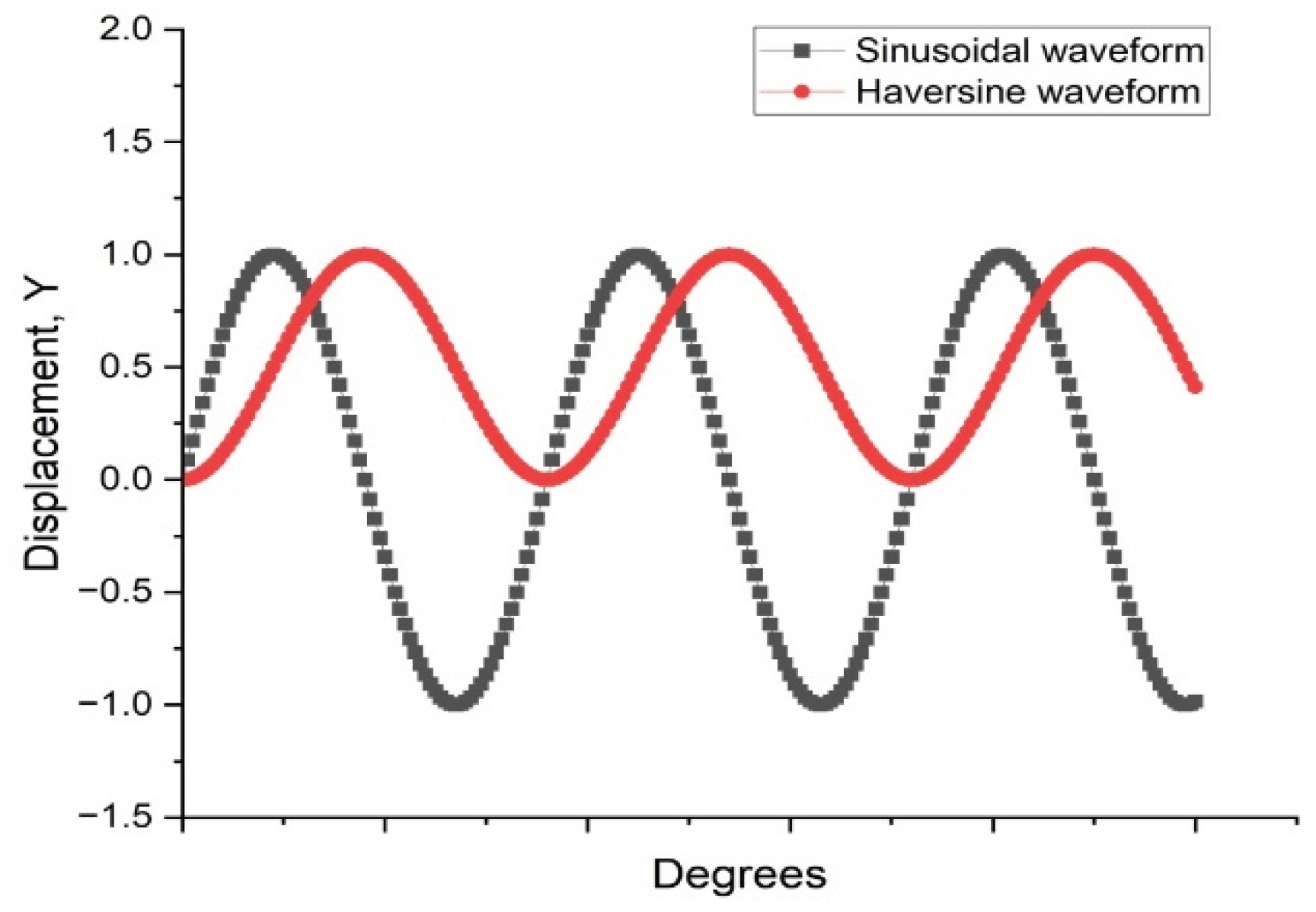
Figure 3.
Schematic of the dynamic shear rheometer.
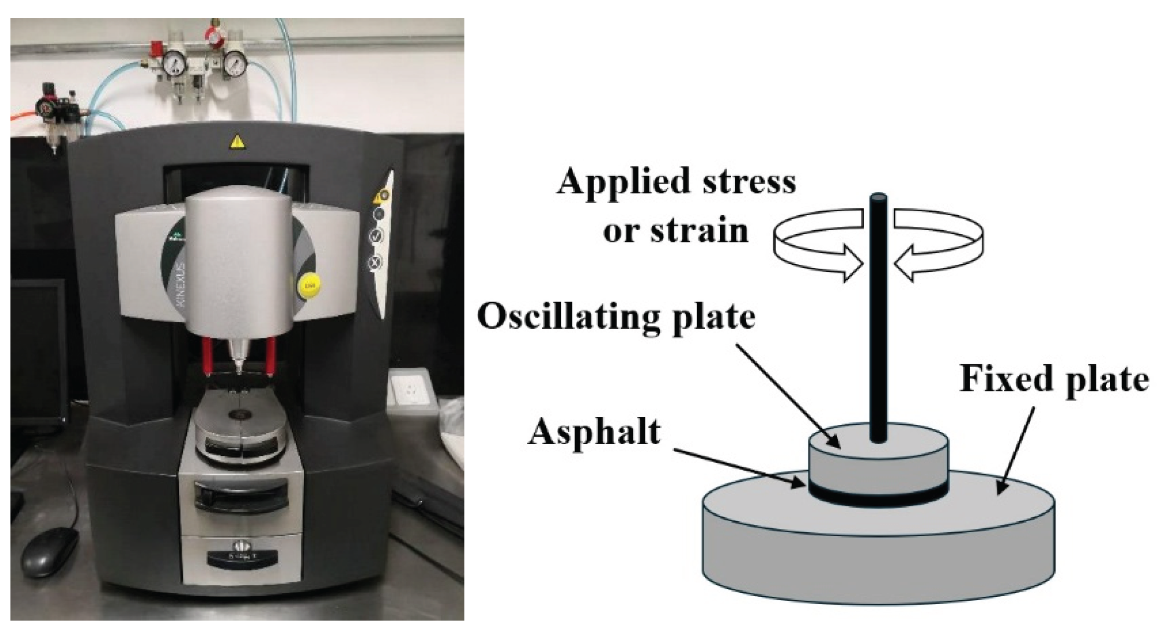
Figure 4.
Schematic view of the annular shear rheometer or ASR (left); picture of the apparatus placed in a thermal chamber (right) [49].
Figure 4.
Schematic view of the annular shear rheometer or ASR (left); picture of the apparatus placed in a thermal chamber (right) [49].
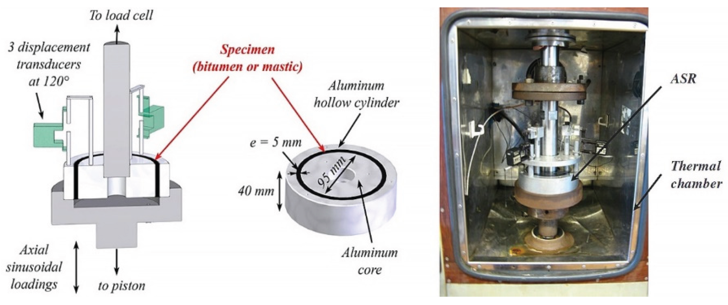
Figure 5.
Fatigue test methods of FAM: (a) uniaxial fatigue test setup for FAM sample [50]; and (b) dynamic mechanical analyzer (DMA) dual-cantilever bending fixture [51].
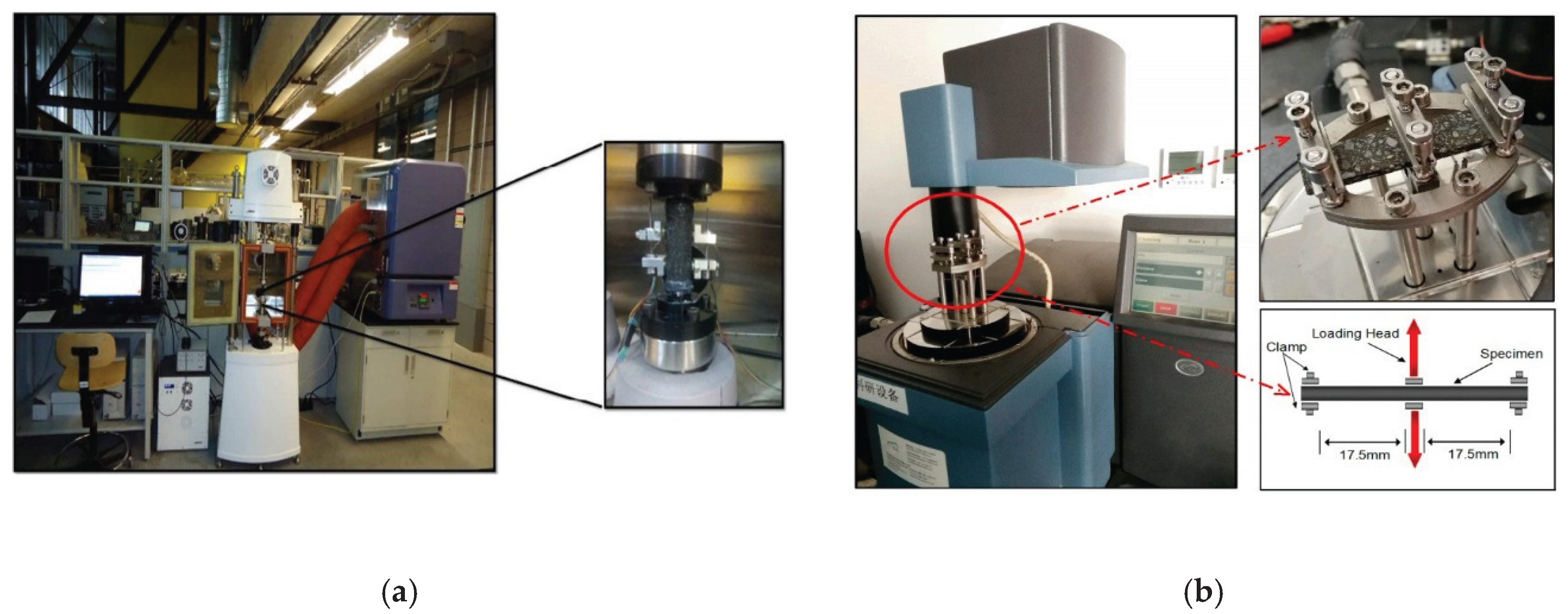
Figure 6.
The fatigue test methods of AC [1].
Figure 6.
The fatigue test methods of AC [1].
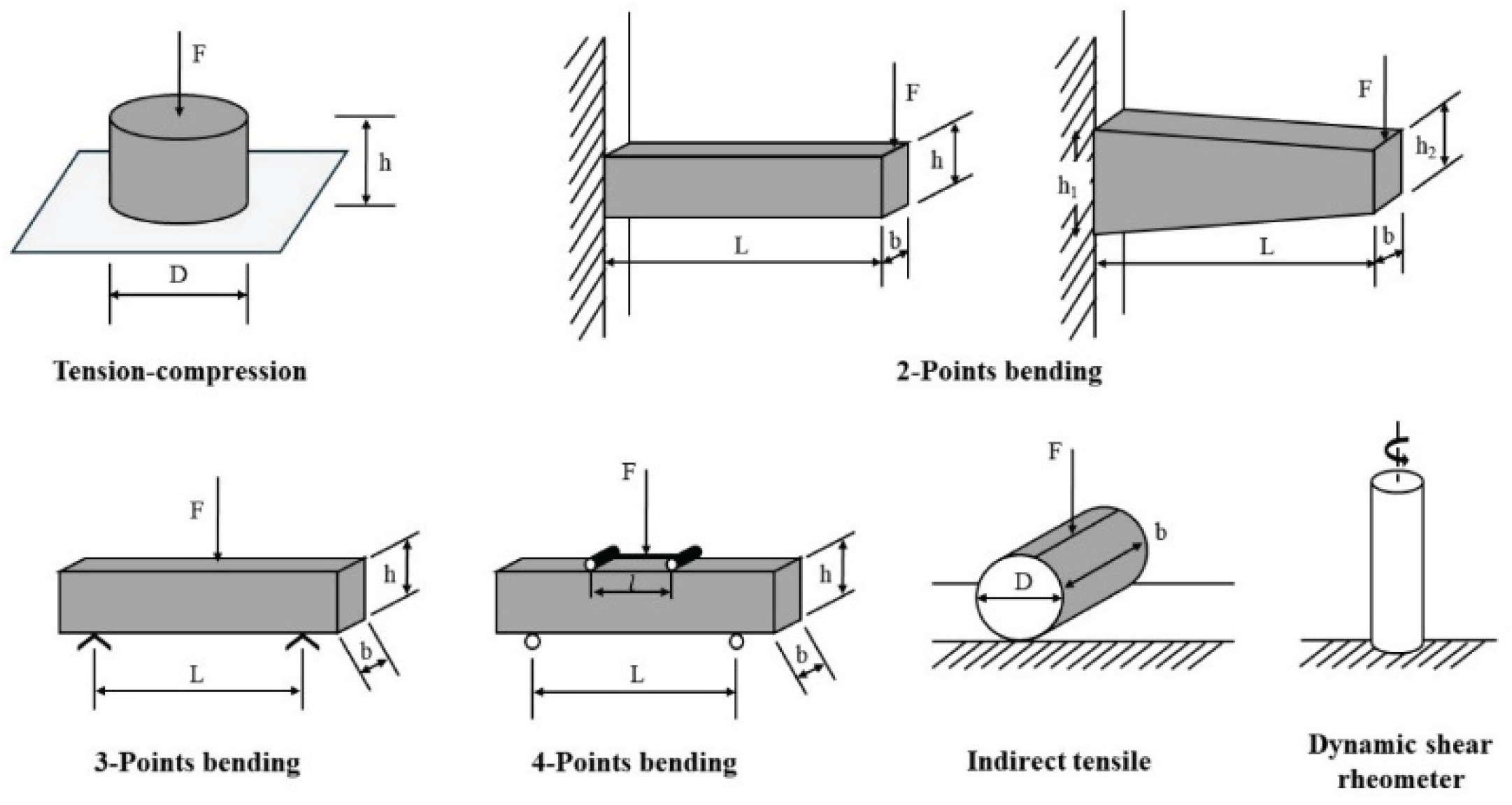
Figure 7.
Evolution of the stiffness (complex modulus) corresponding to the number of load cycles under controlled strain and controlled stress modes [7].
Figure 7.
Evolution of the stiffness (complex modulus) corresponding to the number of load cycles under controlled strain and controlled stress modes [7].
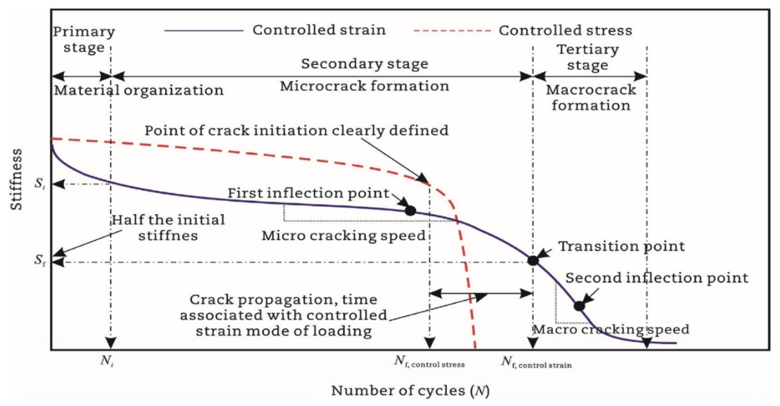
Figure 8.
The schematic diagram of fatigue failure criteria at 25%, 30% and 50% decrease in initial stiffness modulus.
Figure 8.
The schematic diagram of fatigue failure criteria at 25%, 30% and 50% decrease in initial stiffness modulus.
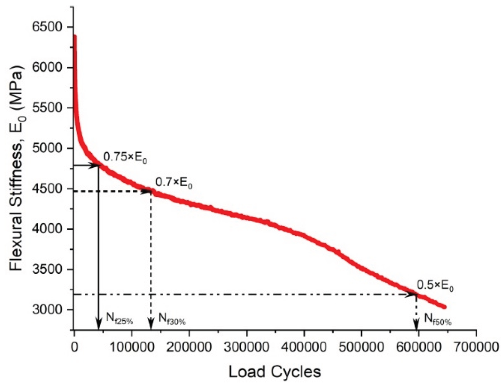
Figure 9.
Variation in phase angle versus the loading cycles.
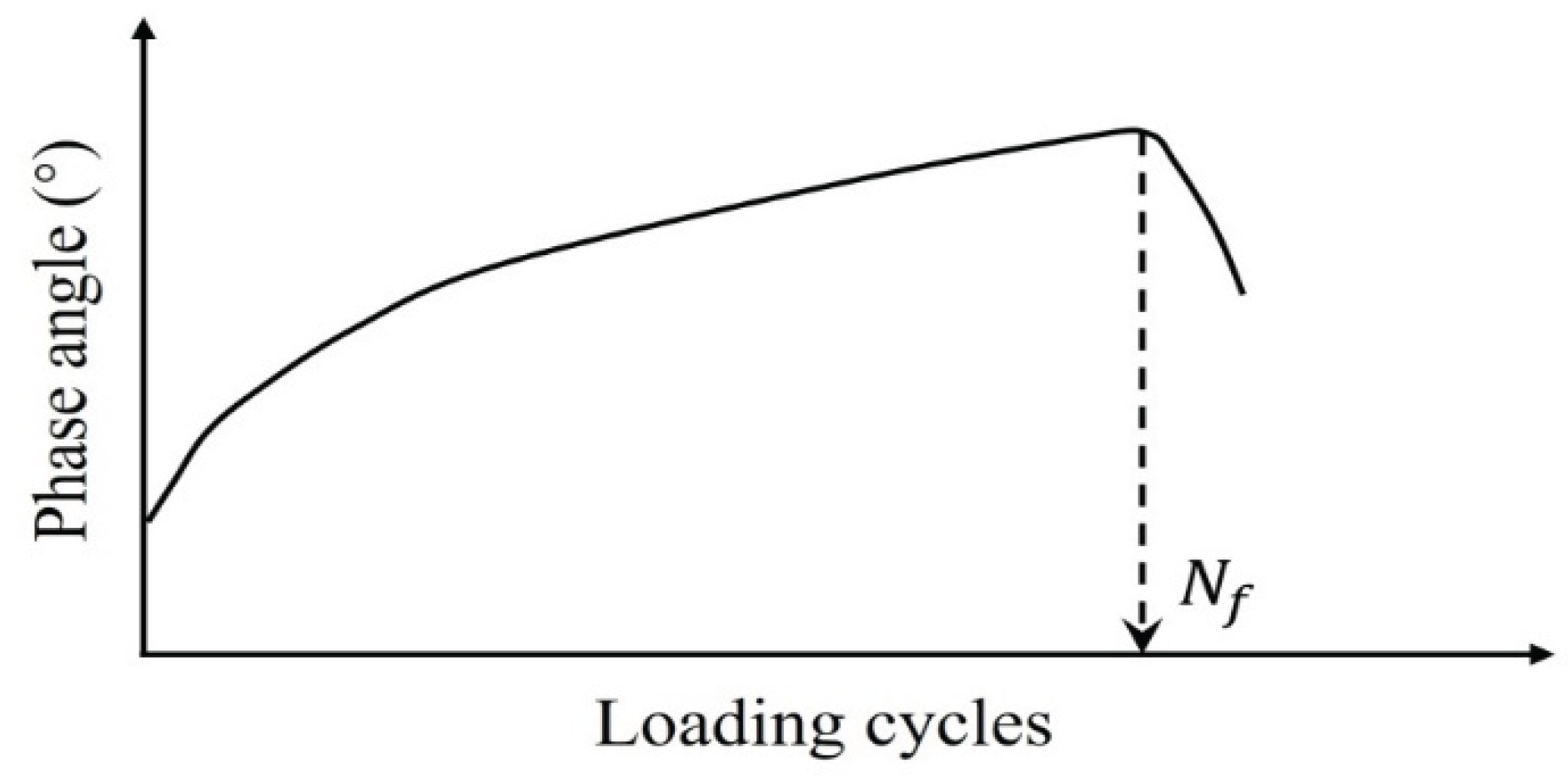
Figure 10.
Viscoelastic properties [1]: (a) stress versus strain relationship (hysteresis loops); (b and c) hysteresis loops at different number of cycles; (d) distorted hysteresis loop.
Figure 10.
Viscoelastic properties [1]: (a) stress versus strain relationship (hysteresis loops); (b and c) hysteresis loops at different number of cycles; (d) distorted hysteresis loop.
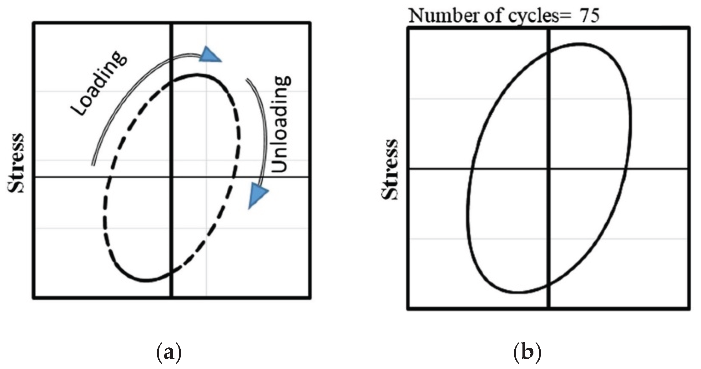
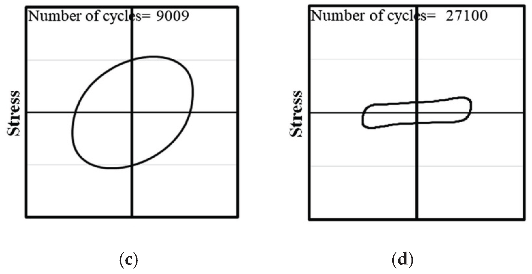
Figure 11.
R-squared failure criterion [133].
Figure 11.
R-squared failure criterion [133].
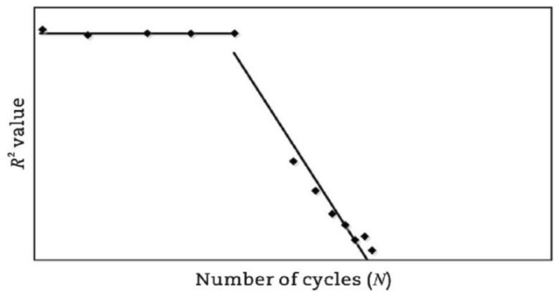
Figure 12.
(a) Axial strain amplitude differences criterion; (b) phase angle axial displacement differences criterion [94].
Figure 12.
(a) Axial strain amplitude differences criterion; (b) phase angle axial displacement differences criterion [94].
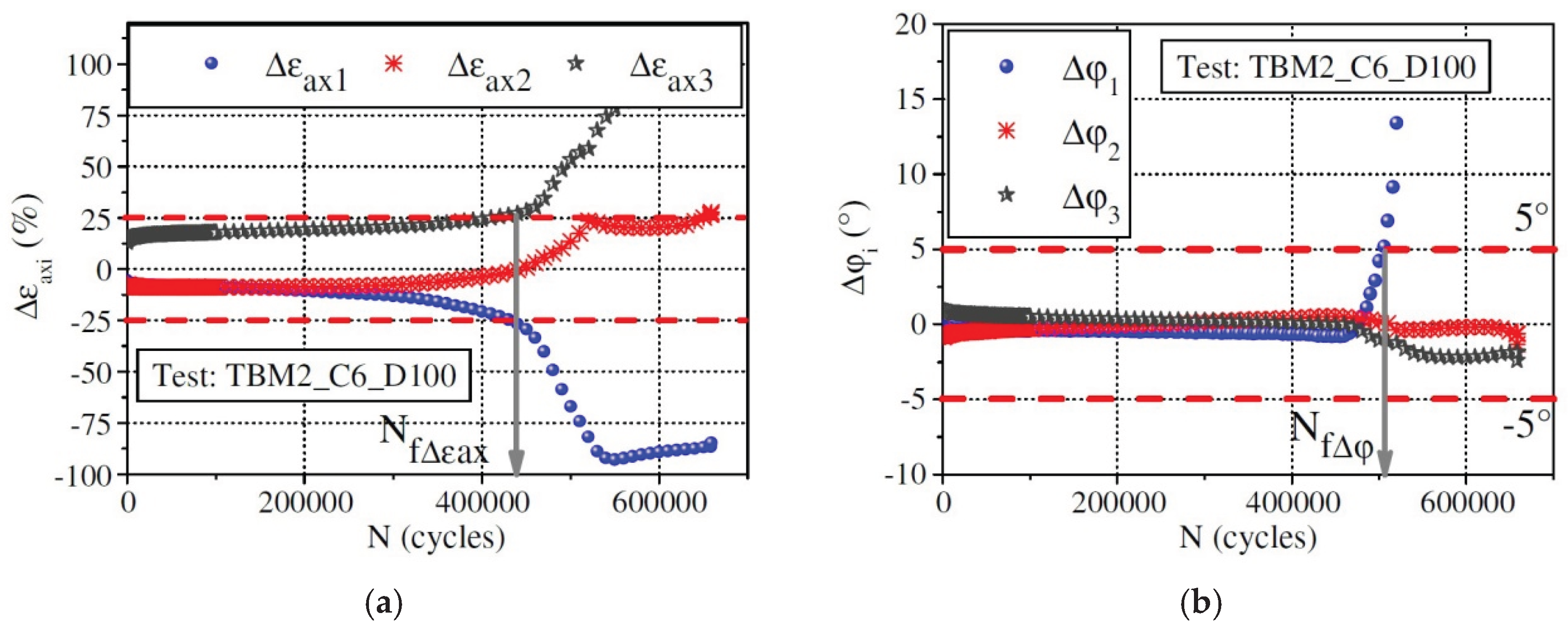
Figure 13.
The schematic diagram of dissipated energy[137].
Figure 13.
The schematic diagram of dissipated energy[137].
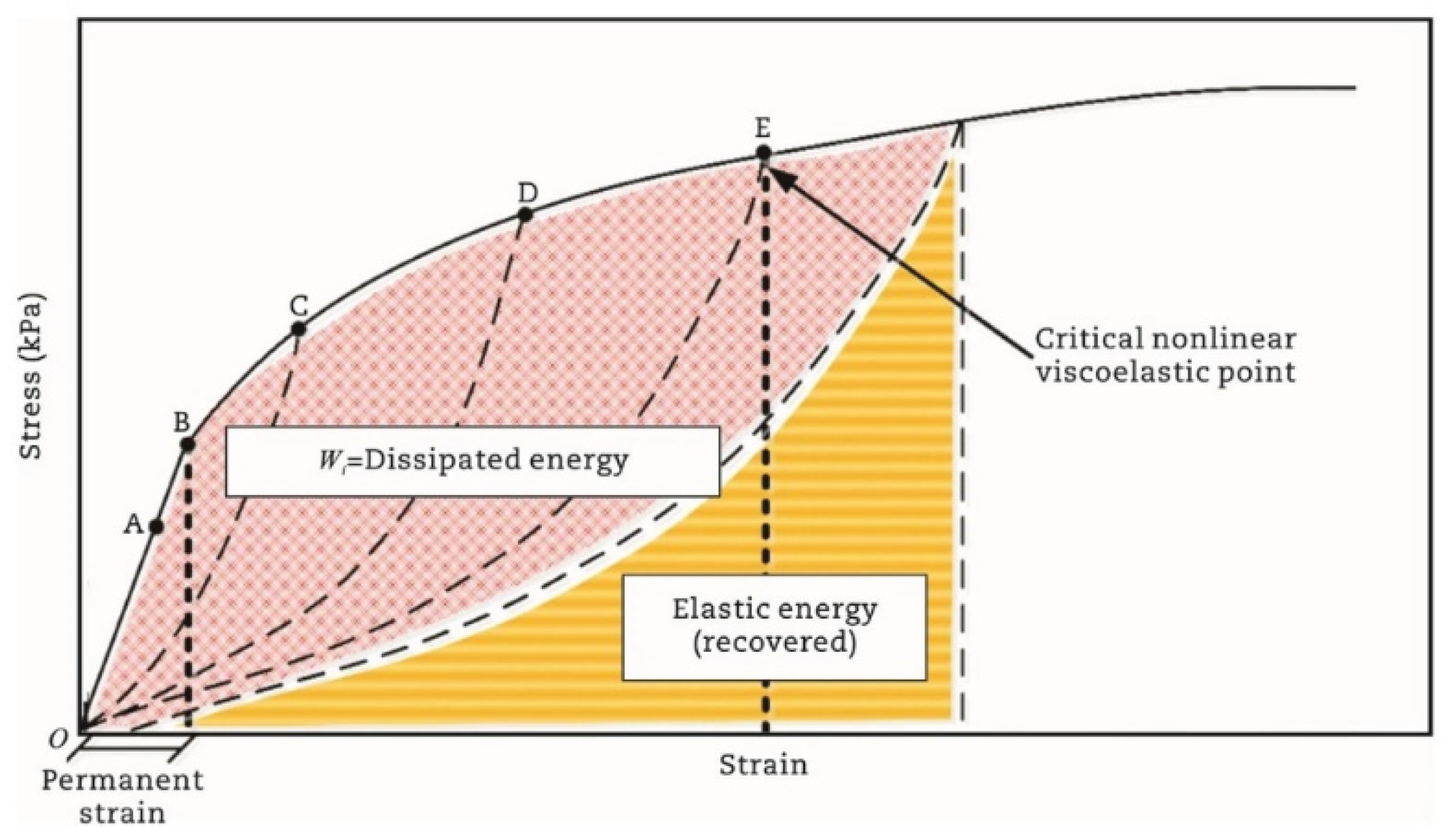
Figure 14.
Different stress-strain hysteresis loops for the same mixture [138].
Figure 14.
Different stress-strain hysteresis loops for the same mixture [138].
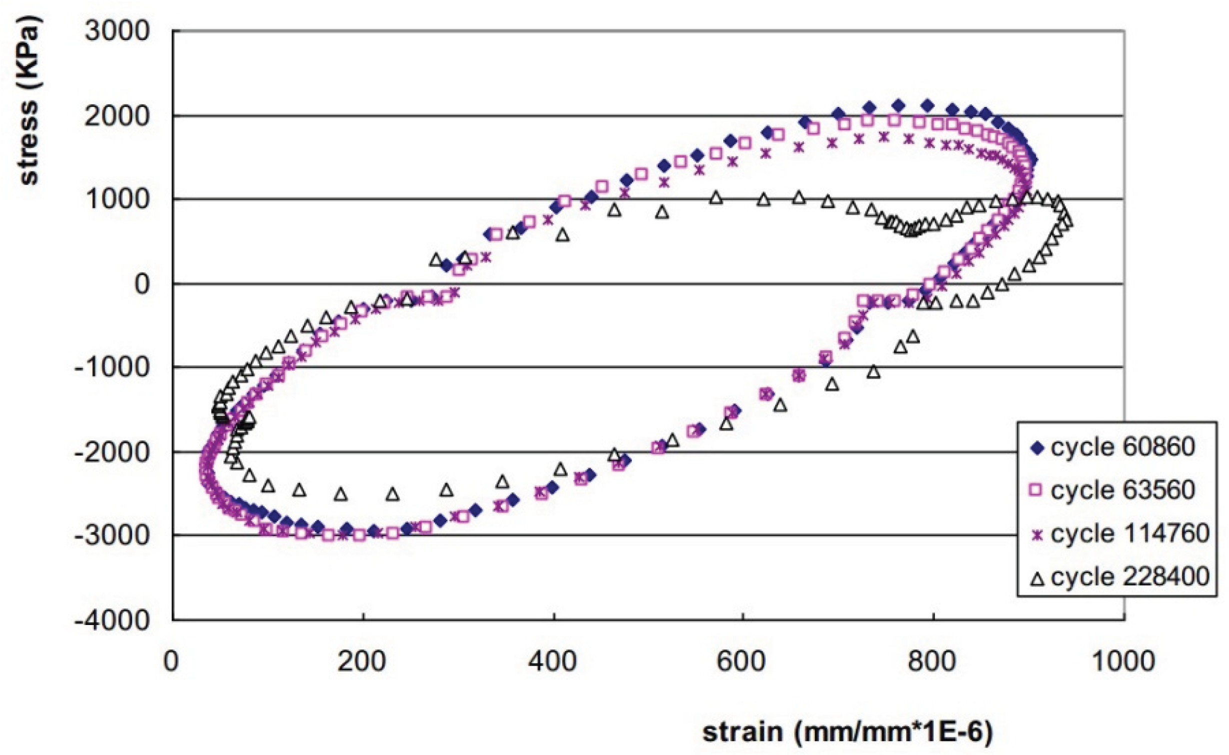
Figure 15.
Energy ratio plot and dissipated energy plot for (a) controlled strain mode for HMA mixture; (b) controlled stress mode for HMA mixture; (c) controlled strain mode for asphalt binder; and (d) controlled stress mode for asphalt binder [126].
Figure 15.
Energy ratio plot and dissipated energy plot for (a) controlled strain mode for HMA mixture; (b) controlled stress mode for HMA mixture; (c) controlled strain mode for asphalt binder; and (d) controlled stress mode for asphalt binder [126].
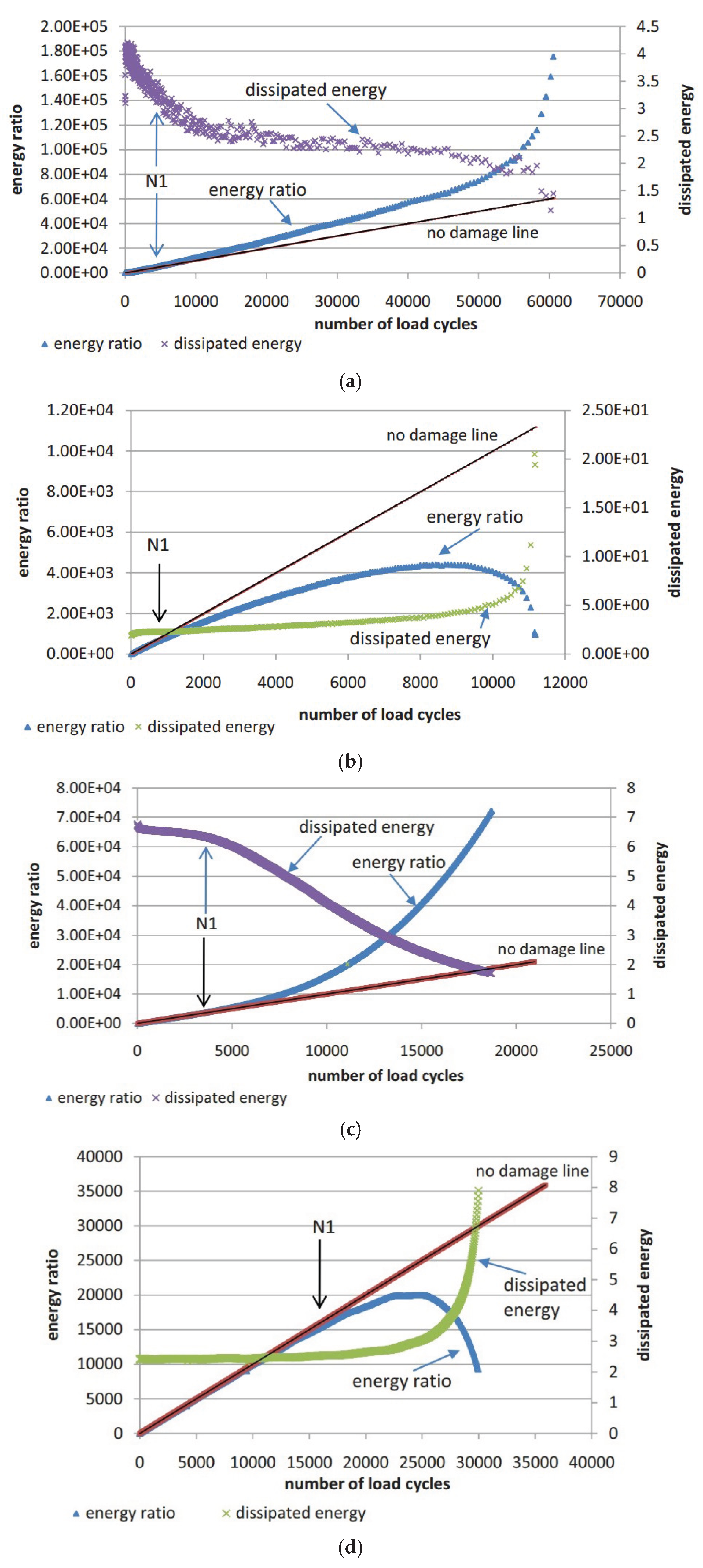
Figure 16.
Energy ratio criteria of Pronk’s approach [147].
Figure 16.
Energy ratio criteria of Pronk’s approach [147].
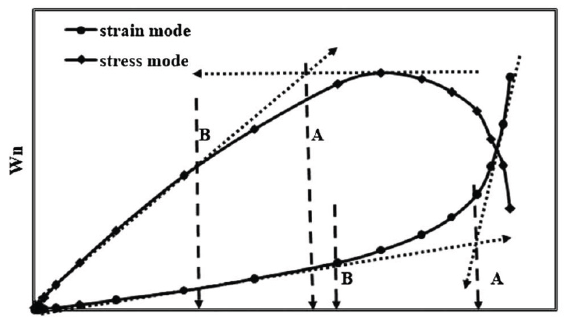
Figure 17.
Stiffness degradation ratio for strain and stress mode of loading.
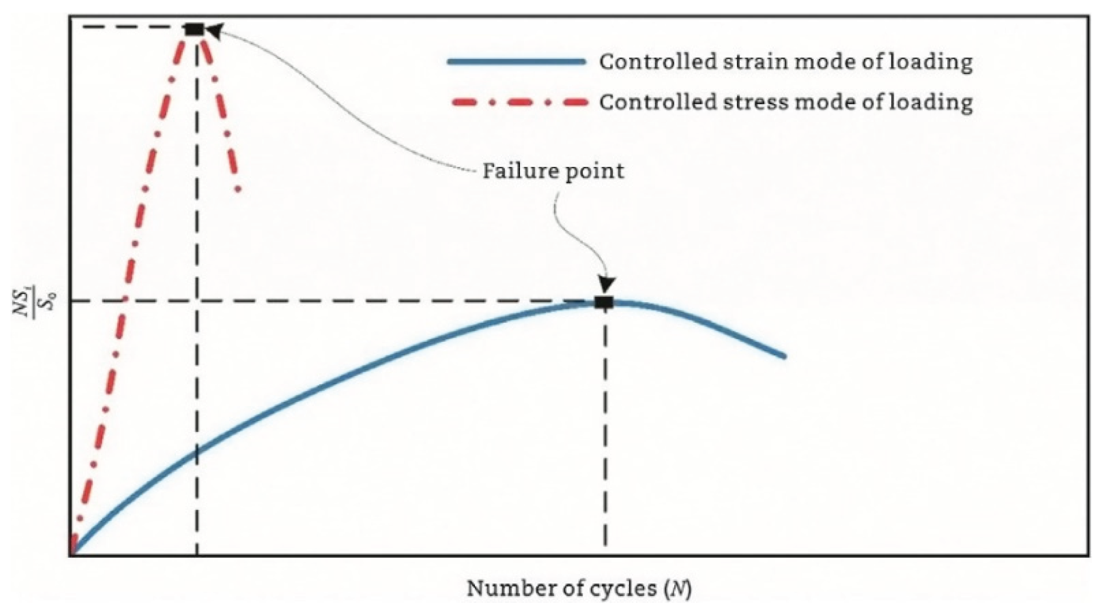
Figure 18.
The failure criteria in AASHTO and ASTM.
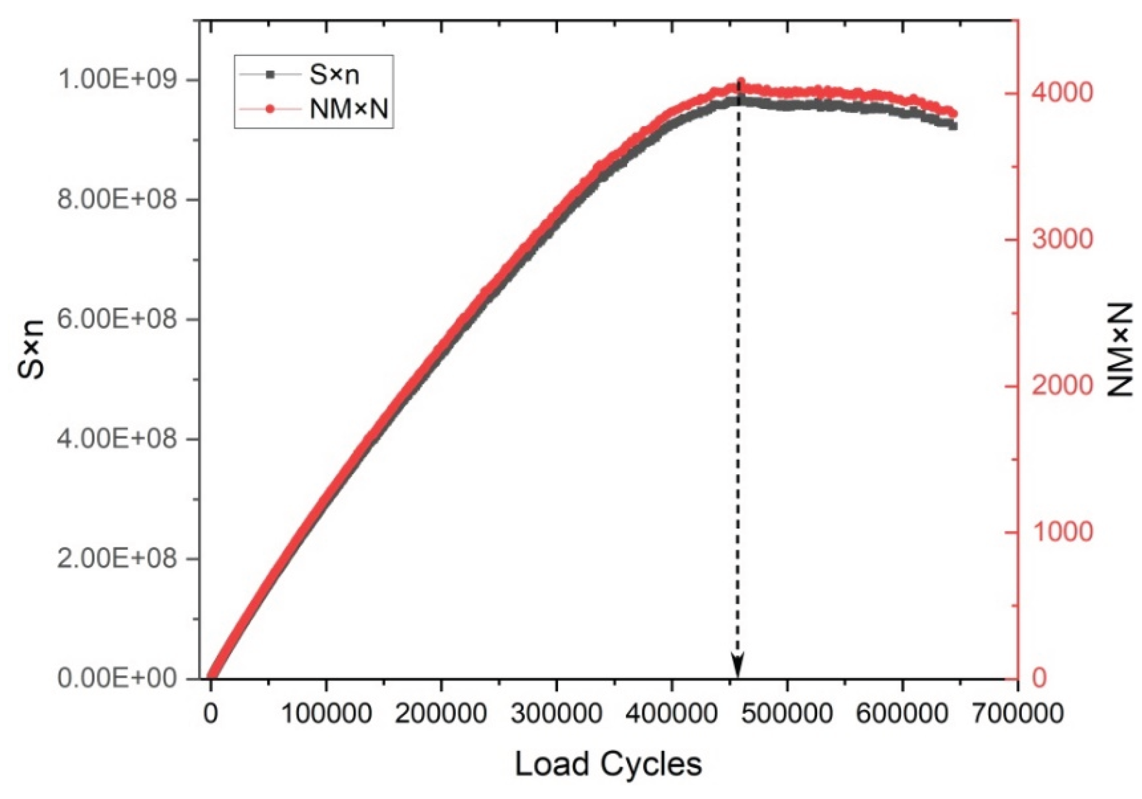
Figure 19.
Resilient modulus (stiffness) ratio versus number of cycles [11].
Figure 19.
Resilient modulus (stiffness) ratio versus number of cycles [11].
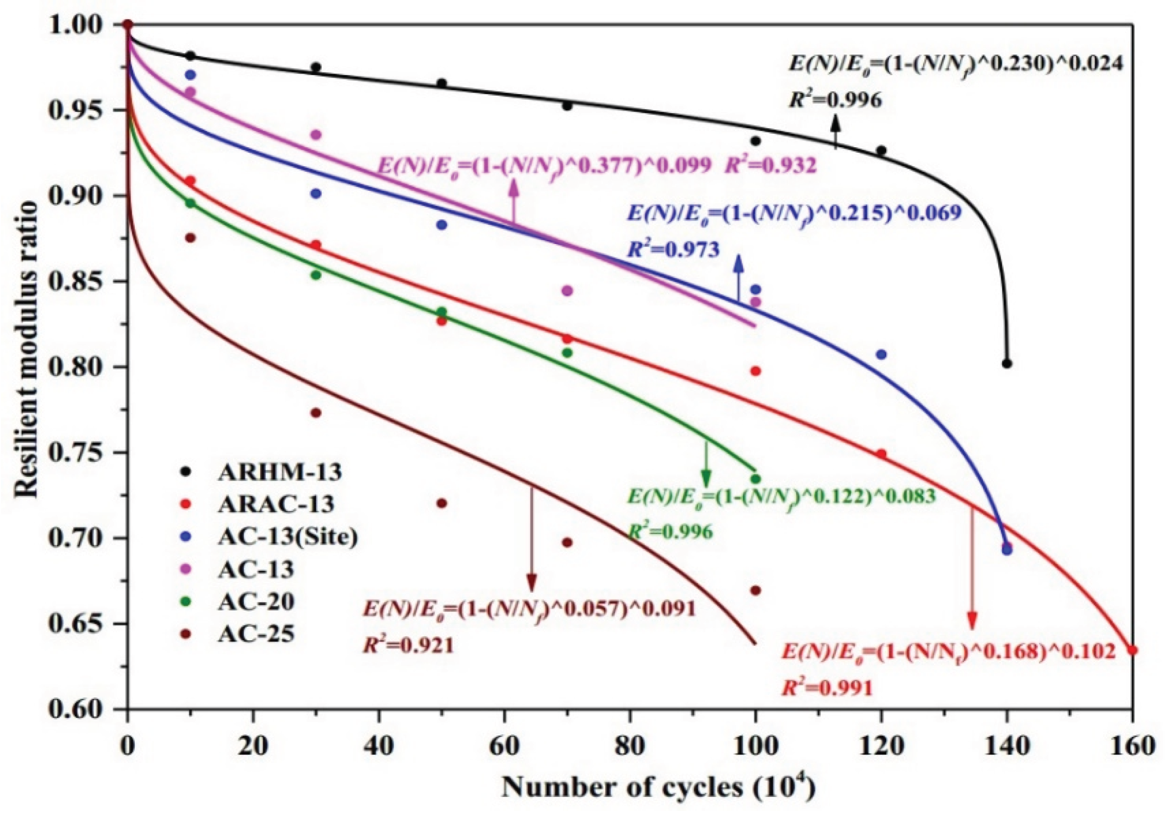
Figure 20.
Stiffness modulus degradation ratio under different test conditions (modified after Ref [153]): (a) under different stress ratios (25℃, 10 mm/min); (b) under different temperatures (stress ratio = 0.6, 10 mm/min); and (c) under different load rates (stress ratio = 0.6, 5℃).
Figure 20.
Stiffness modulus degradation ratio under different test conditions (modified after Ref [153]): (a) under different stress ratios (25℃, 10 mm/min); (b) under different temperatures (stress ratio = 0.6, 10 mm/min); and (c) under different load rates (stress ratio = 0.6, 5℃).
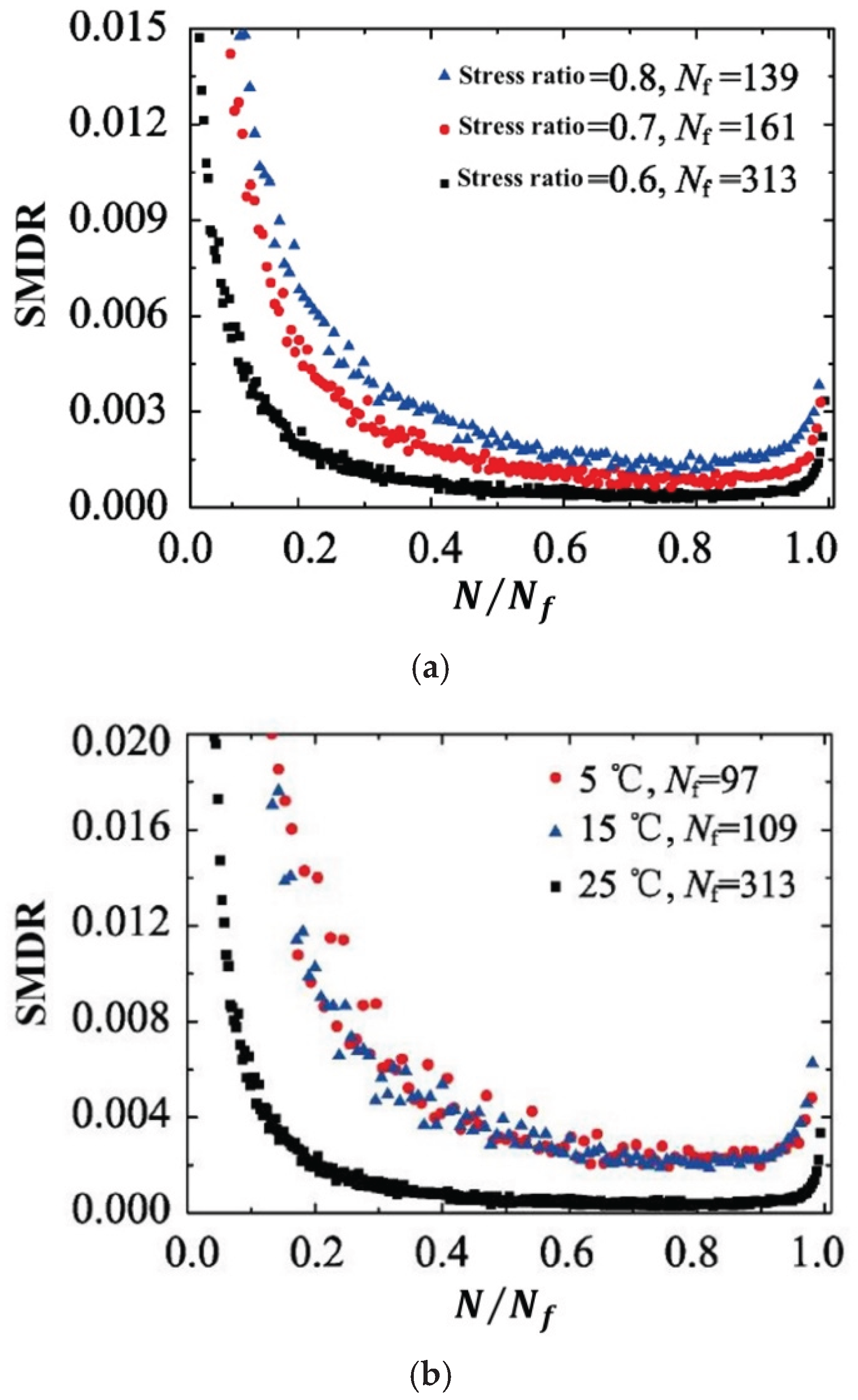
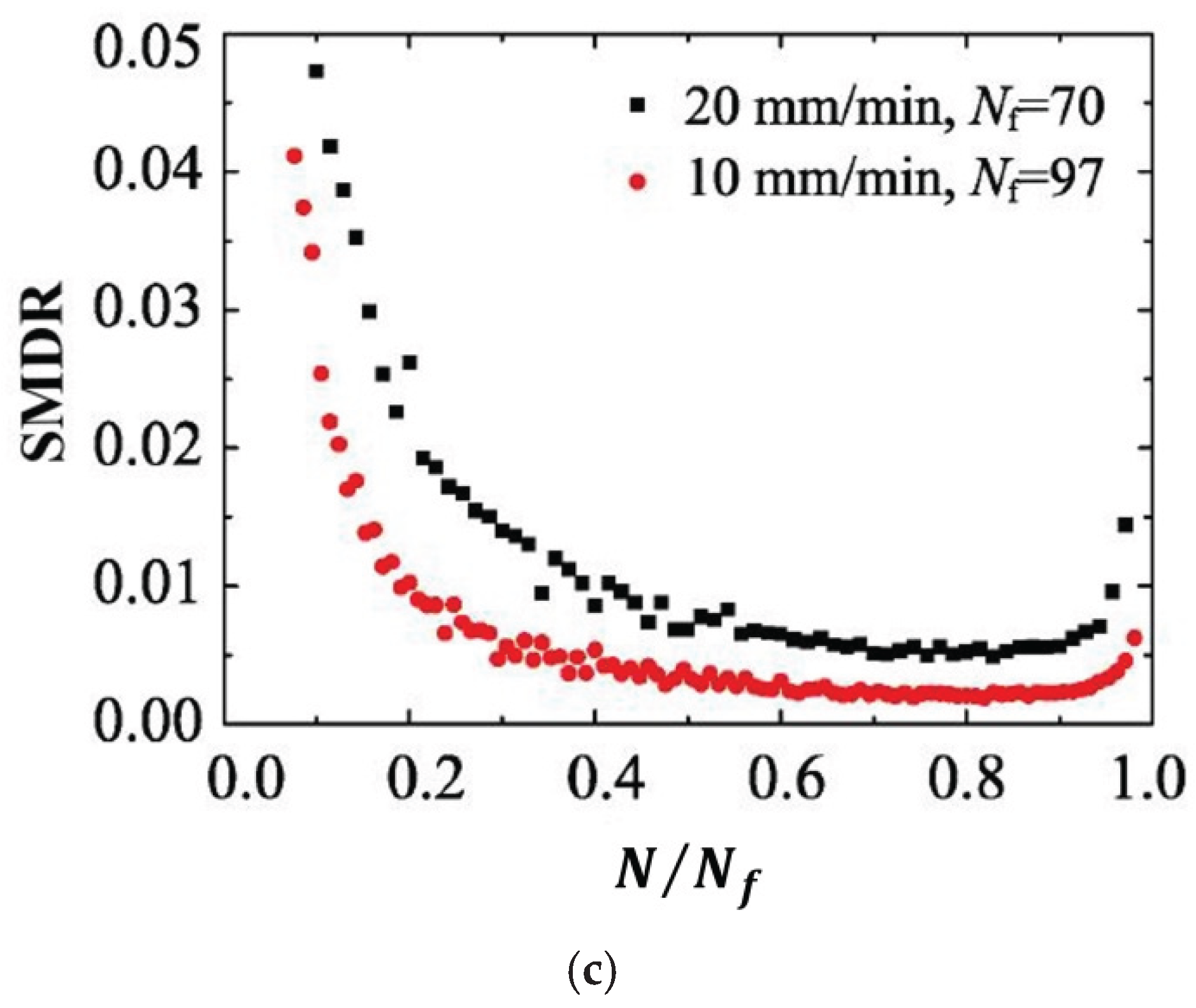
Figure 21.
Stress degradation ratio [7].
Figure 21.
Stress degradation ratio [7].
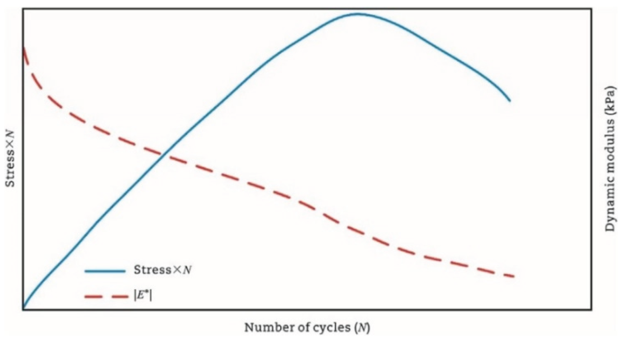
Figure 22.
The schematic of end failure locations [155].
Figure 22.
The schematic of end failure locations [155].
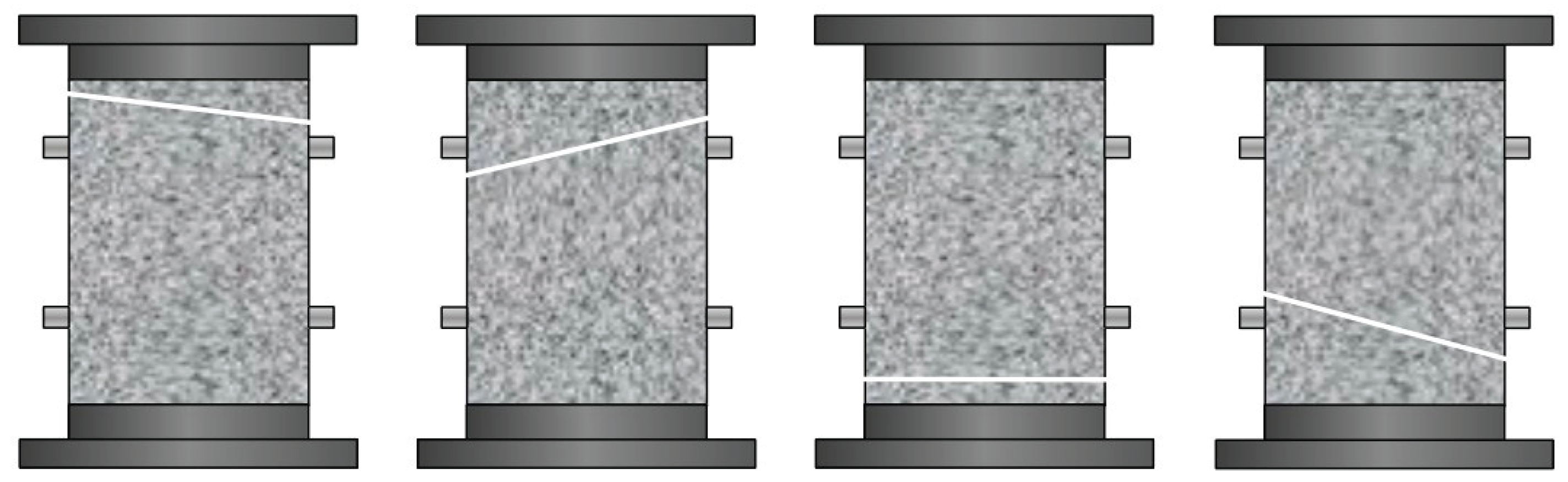
Figure 23.
Typical
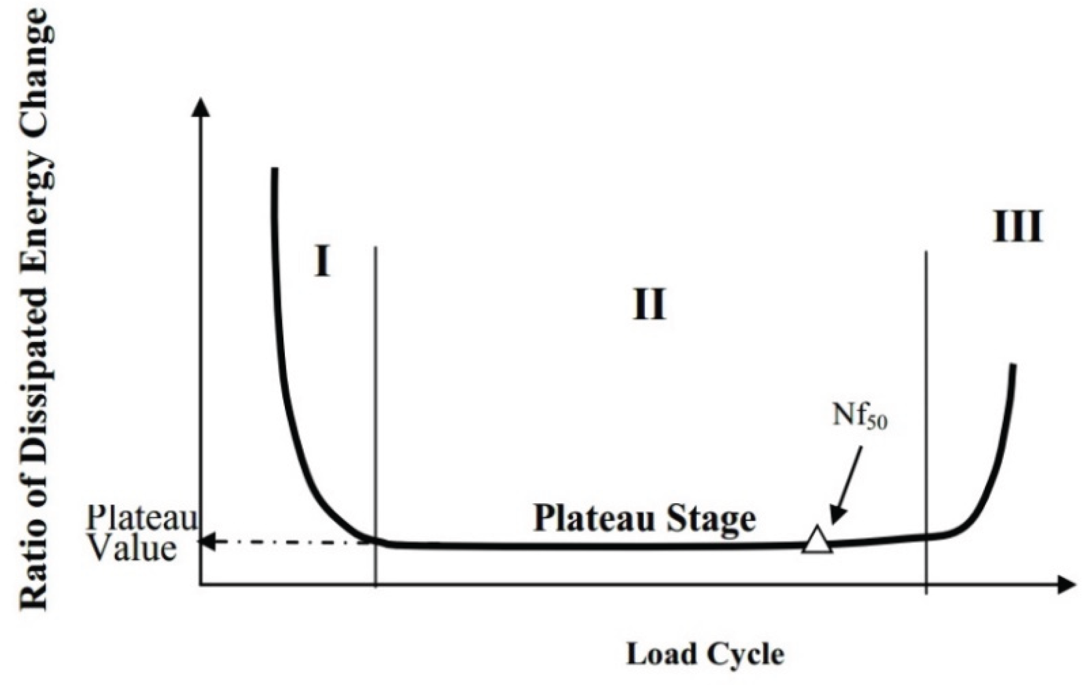
Figure 24.
The relationship of the RDEC versus the number of load cycles and the indication of PV from fatigue testing [142].
Figure 24.
The relationship of the RDEC versus the number of load cycles and the indication of PV from fatigue testing [142].
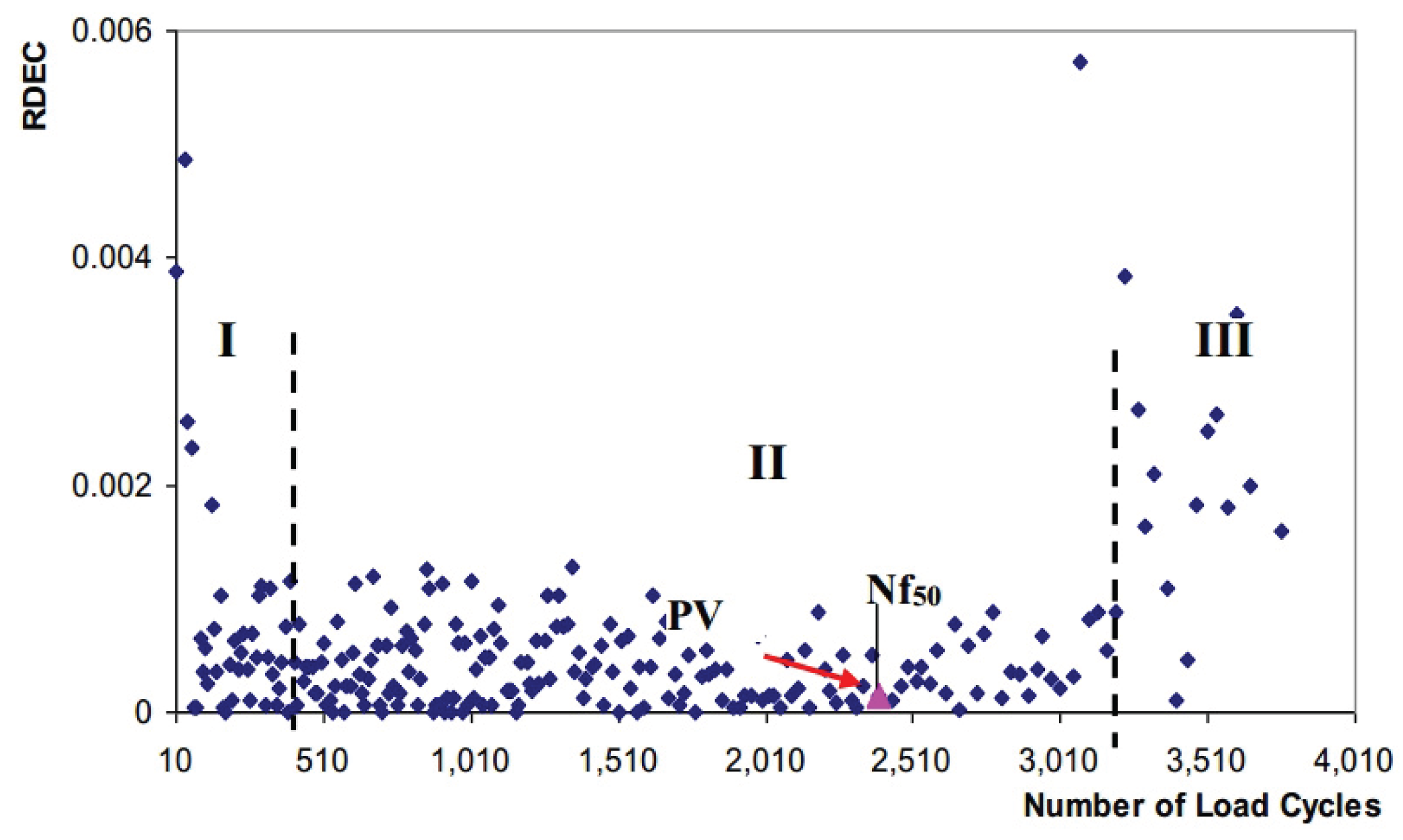
Figure 25.
Contrast result of DER (the former version of RDEC) of rubber asphalt mixture [165].
Figure 25.
Contrast result of DER (the former version of RDEC) of rubber asphalt mixture [165].
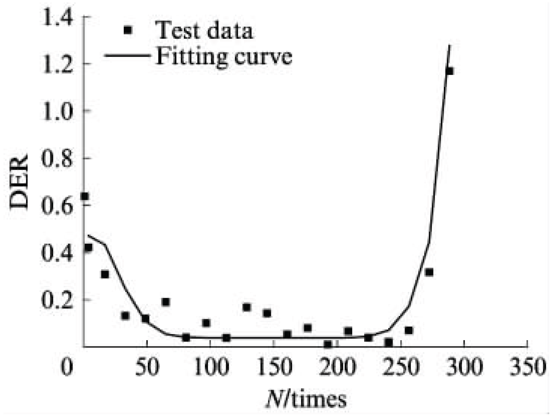
Figure 26.
The relationship of
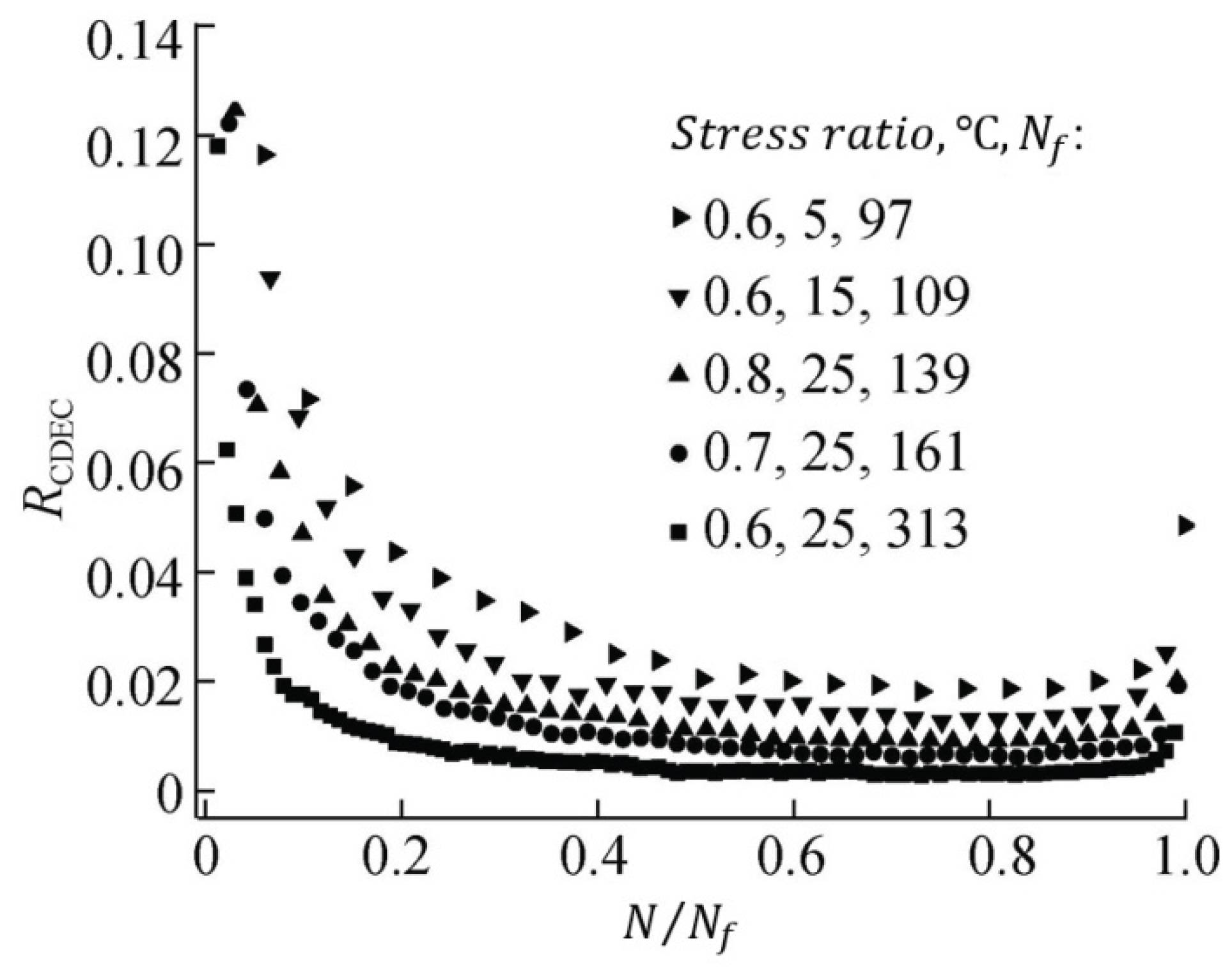
Figure 27.
Determination of failure limits in asphalt mixtures.

Figure 28.
Diagram of damage threshold [170].
Figure 28.
Diagram of damage threshold [170].
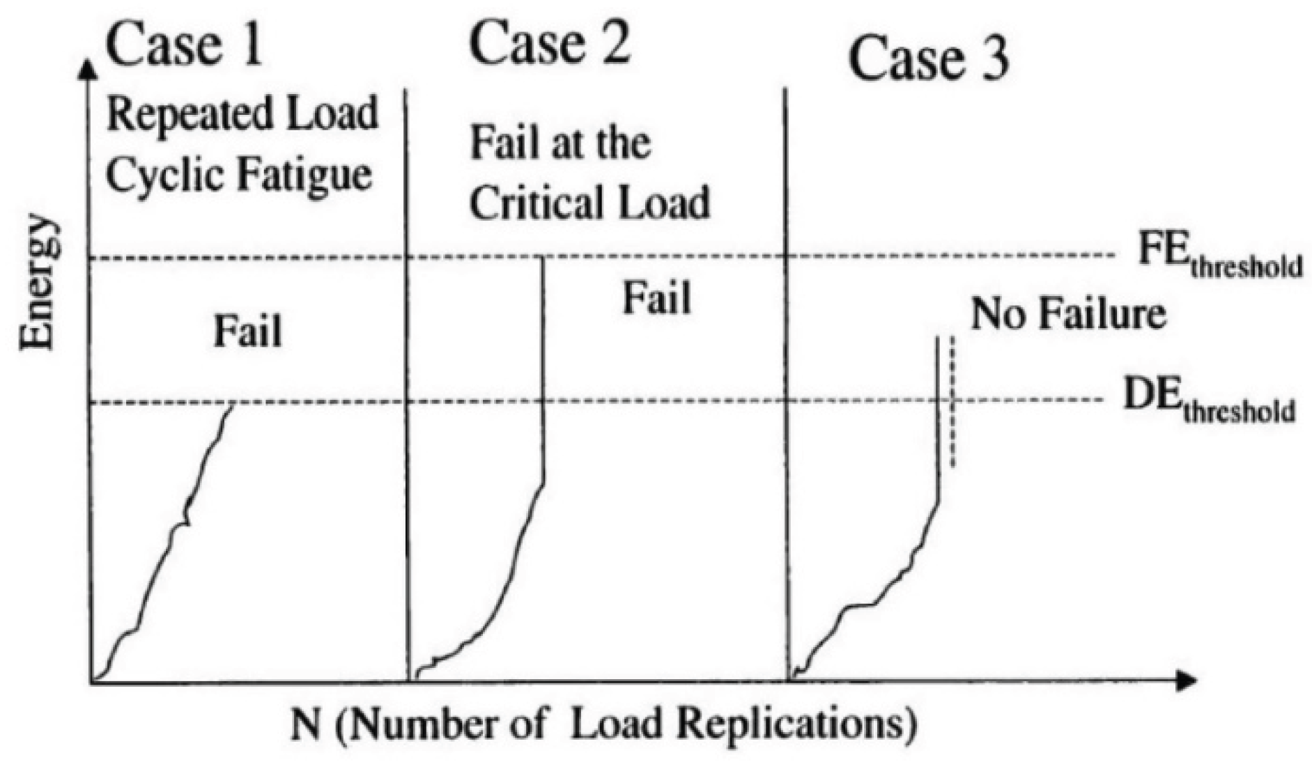
Figure 29.
Schematic diagram of healing effect of asphalt mixture [170].
Figure 29.
Schematic diagram of healing effect of asphalt mixture [170].
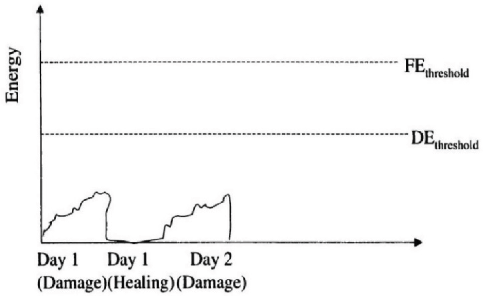
Figure 30.
The diagram of Paris’s Law.
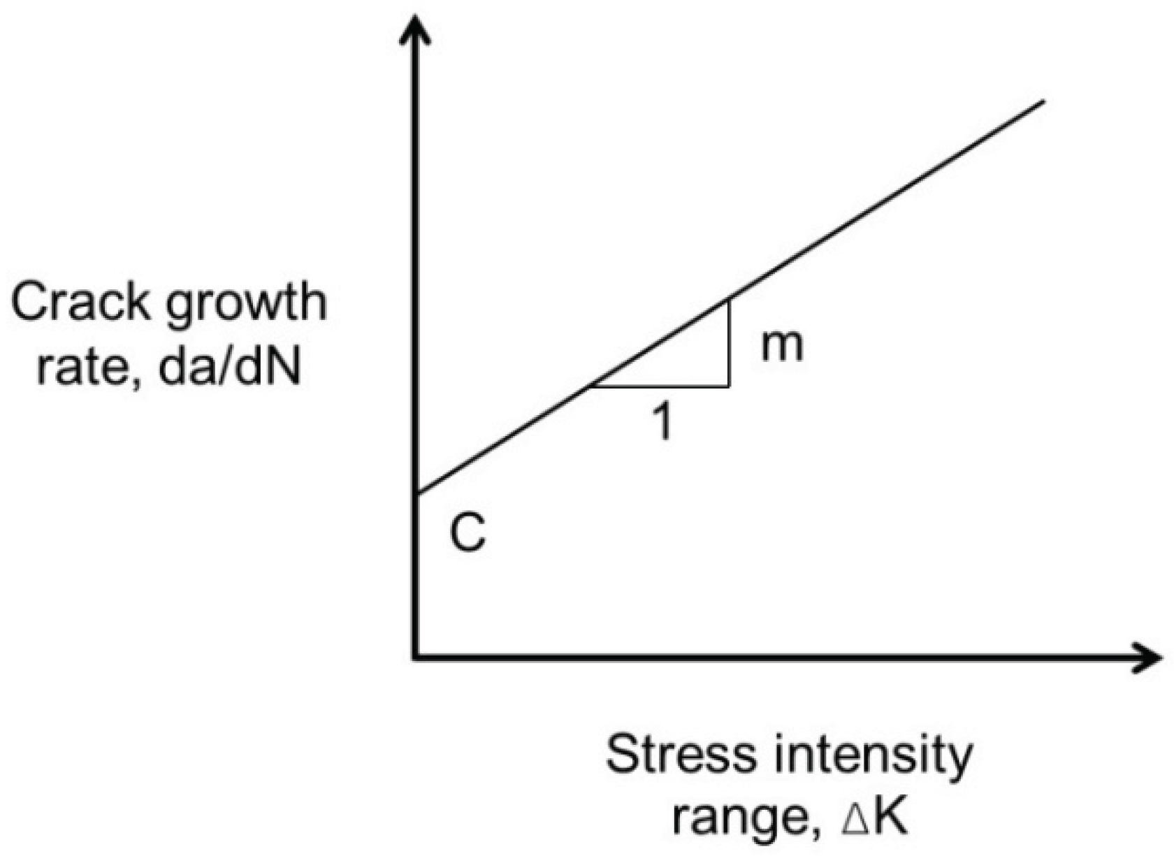
Figure 31.
Rate of crack growth versus stress intensity factor in the three phases of crack propagation [176].
Figure 31.
Rate of crack growth versus stress intensity factor in the three phases of crack propagation [176].
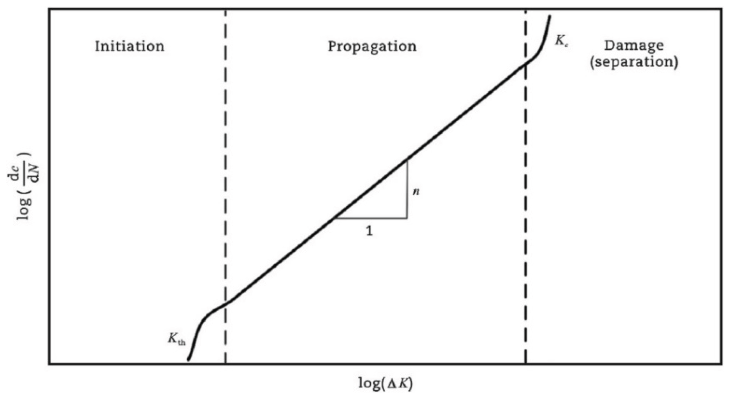
Figure 32.
Pseudo hysteresis loops for controlled crosshead (CX) cyclic direct tension tests [124].
Figure 32.
Pseudo hysteresis loops for controlled crosshead (CX) cyclic direct tension tests [124].
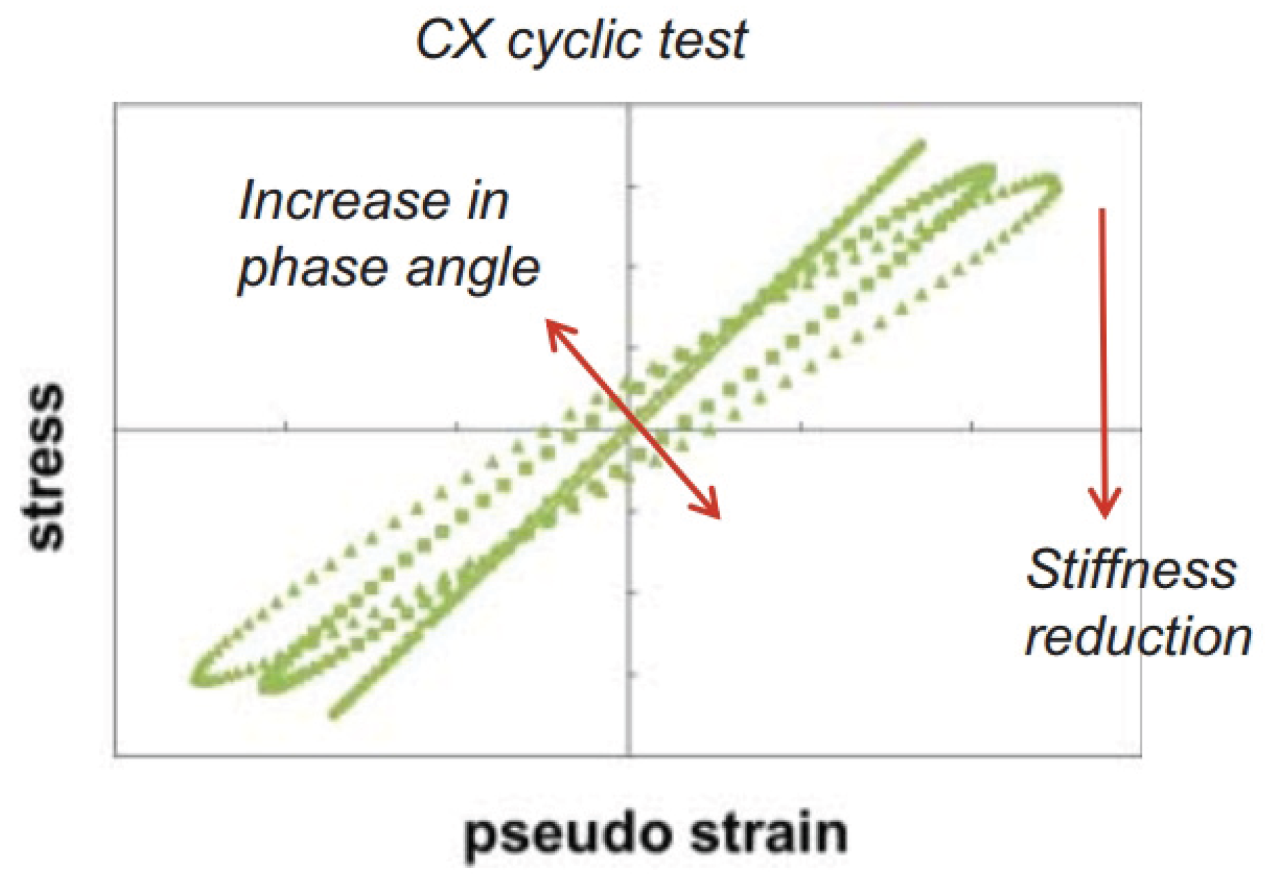
Figure 33.
Pseudo strain energy compositions [1].
Figure 33.
Pseudo strain energy compositions [1].
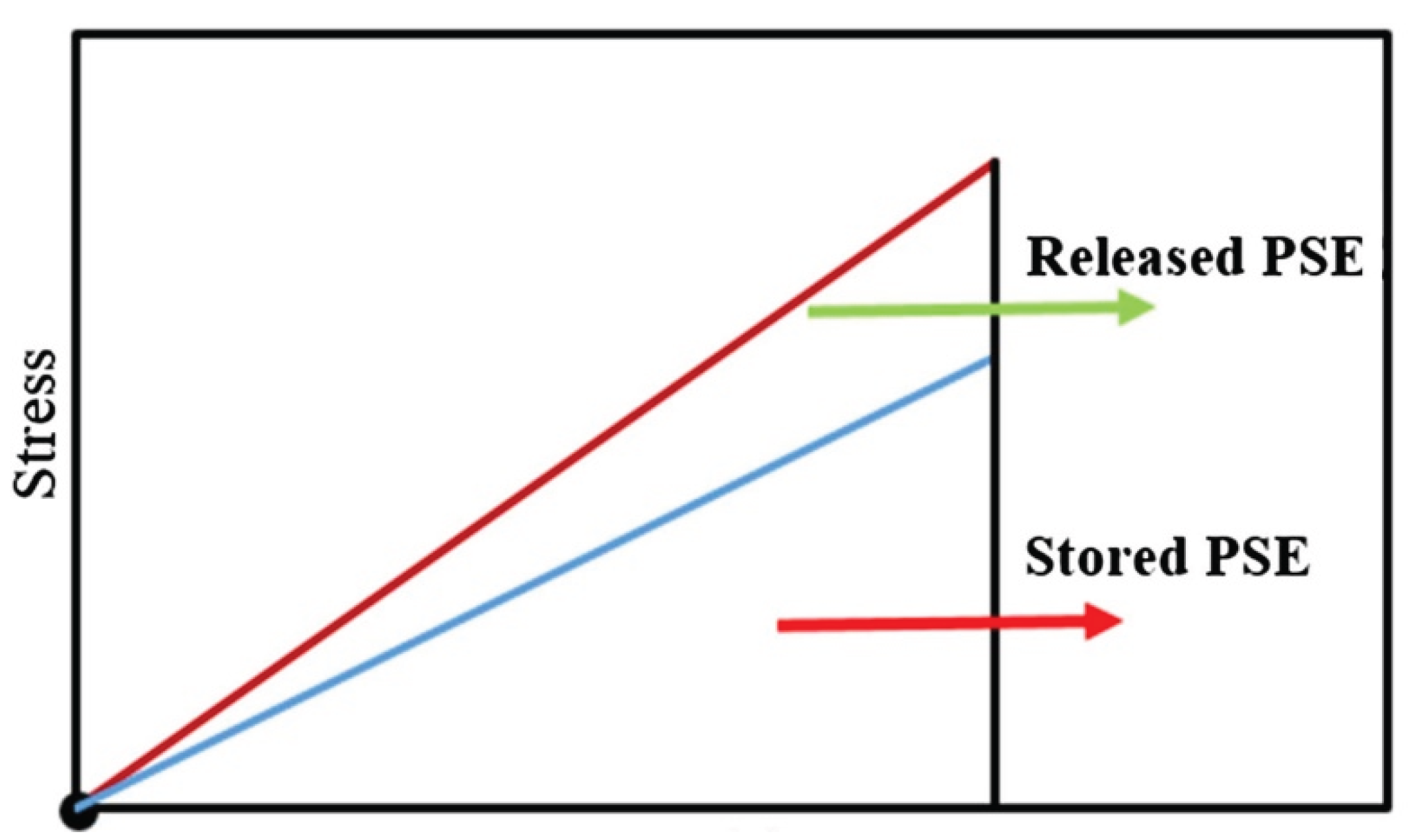
Figure 34.
Zhang et al.’s approach: (a) the history of

Figure 35.
Relationship between
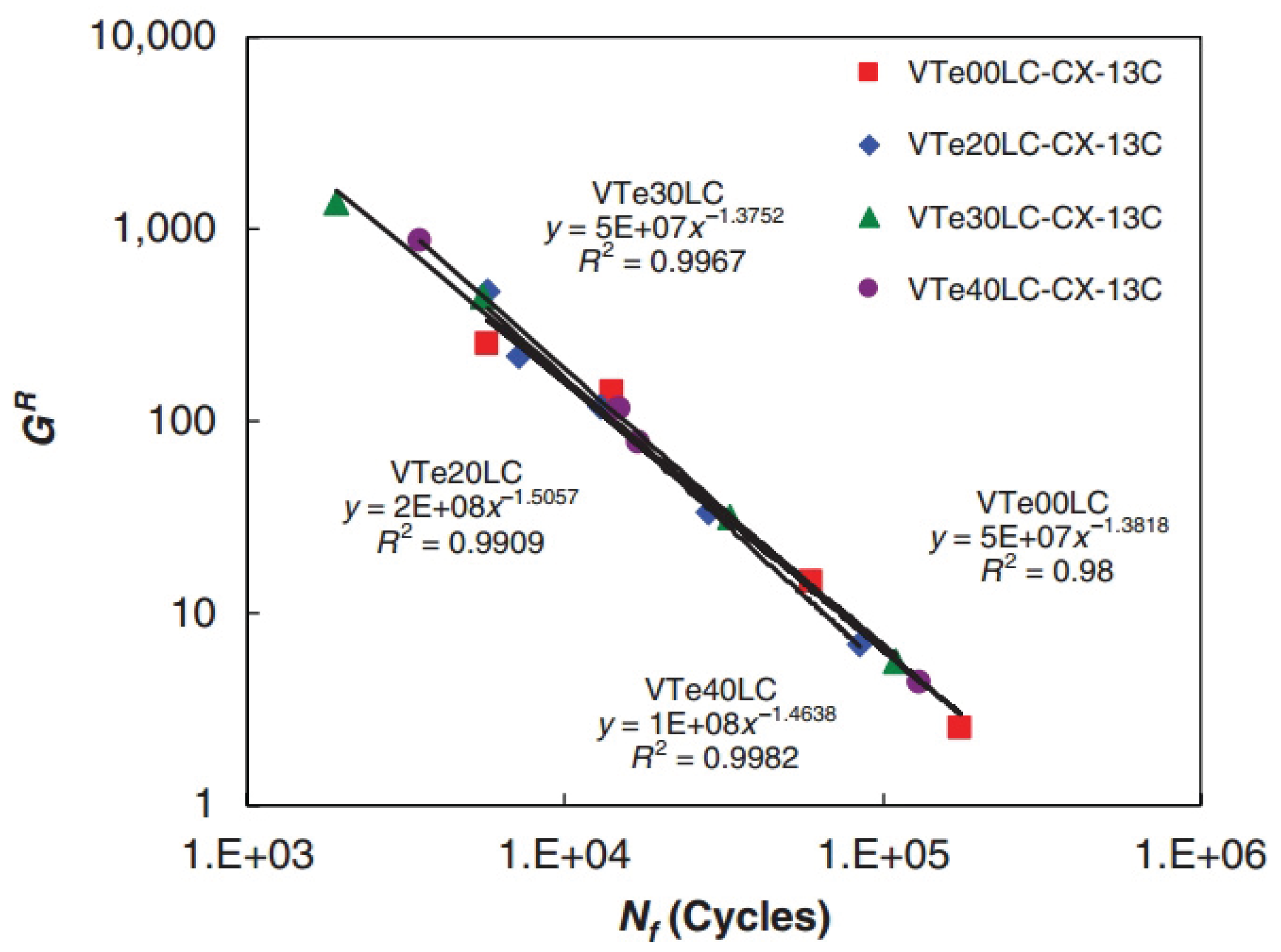
Figure 36.
Relationship between
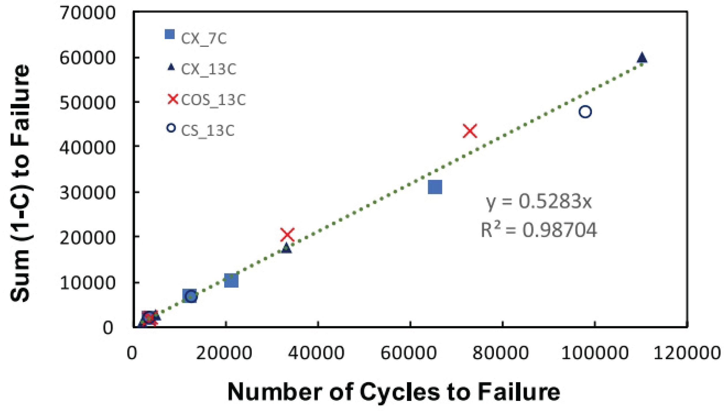

Table 1.
Loading modes and schematic diagrams of specimens under different fatigue tests.
| Loading Mode/Test Tpye | Schematic Diagram | Material Type | Reference |
|---|---|---|---|
| Uniaxial compression/tension (UT/UC) | 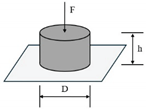 |
AC | [26,33,52,53] |
| Beam bending (BB) |
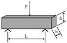 Three-point bending (3PB) |
AC | [54,55] |
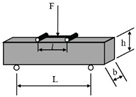 Four-point bending (4PB) |
[34,35] | ||
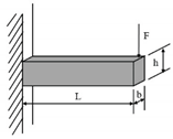 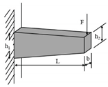 Two-point bending (2PB) |
[56,57,58] | ||
| Indirect tensile (IDT) | 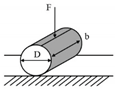 |
AC | [59,60,61,62] |
| Dynamic shearing (DS) |  |
AC | [63,64] |
| Semi-circular bending (SCB) | 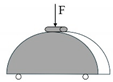 |
AC | [41,65] |
| Dynamic mechanical analyzer (DMA) | 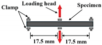 |
FAM | [51,66] |
| Annular shear rheometer (ASR) | 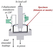 |
Asphalt or mastic | [49,67,68] |
| Linear amplitude sweep (LAS) | 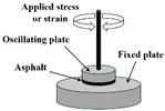 |
Asphalt | [69,70] |
Table 2.
The concepts and schematic diagrams of the fundamental failure criteria.
| Criteria | Indicator | Schematic diagram | Reference |
|---|---|---|---|
| Stiffness modulus reduction criteria | Stiffness modulus | 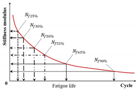 |
[28,31,108,118] |
| Pseudo stiffness | 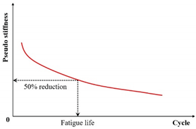 |
[112,113] | |
| Local modulus | 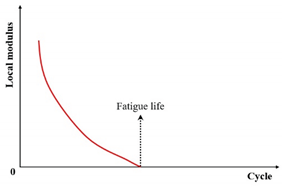 |
[121] | |
| Complete fracture | 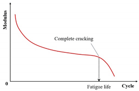 |
[31] | |
| Strain | 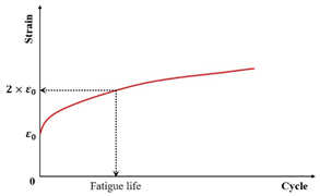 |
[117] | |
| Phase angle criterion | Phase angle | 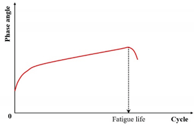 |
[31,130,131] |
| Fitting change-point criterion | R2 value/se value | 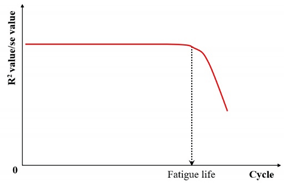 |
[133,134] |
| Specimen homogeneity criterion | ) | 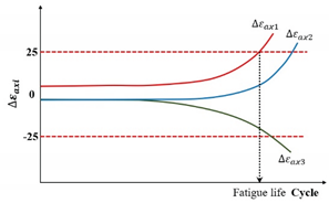 |
[135,136] |
| ) | 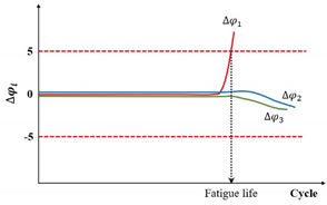 |
Table 3.
The concepts and schematic diagrams of the energy-based failure criteria.
| Criteria | Indicator | Schematic diagram | Reference |
|---|---|---|---|
| Energy ratio criteria | Energy ratio (Wn) | 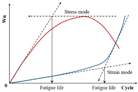 |
[147] |
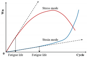 |
[126] | ||
| Stiffness degradation ratio criterion | ) | 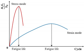 |
[150] |
| The normalized modulus × cycles (NM) | 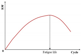 |
[151] | |
| ) | 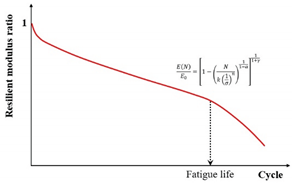 |
[11] | |
| The stiffness modulus degradation ratio (SMDR) | 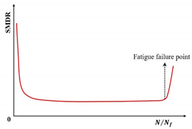 |
[154] | |
| Stress degradation ratio criterion | Stress × N | 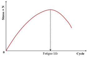 |
[7] |
| Dissipated energy ratio criteria | The dissipated energy ratio (DER) | 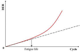 |
[156] |
| The ratio of dissipated energy change (RDEC) | 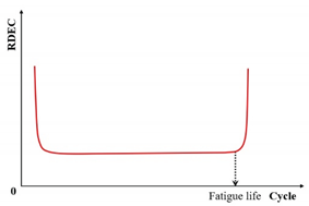 |
[142,143,157] | |
| The ratio of cumulative dissipated energy change (RCDEC) | 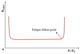 |
[167] | |
| Fracture energy criteria | )) | 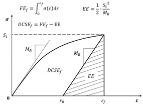 |
[168,170,171] |
Table 4.
The concepts and schematic diagrams of the failure criteria applicable to the VECD model.
| Criteria | Indicator | Schematic diagram | Reference |
|---|---|---|---|
| Pseudo stiffness criterion | The pseudo stiffness value | 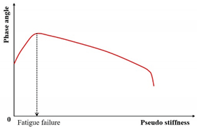 |
[194] |
| -based criterion | is the total released pseudo strain energy | 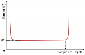 |
[124] |
| -based criterion | ) | 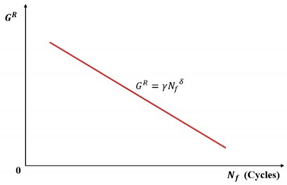 |
[132] |
| -based criterion | ) | 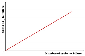 |
[25] |
Disclaimer/Publisher’s Note: The statements, opinions and data contained in all publications are solely those of the individual author(s) and contributor(s) and not of MDPI and/or the editor(s). MDPI and/or the editor(s) disclaim responsibility for any injury to people or property resulting from any ideas, methods, instructions or products referred to in the content. |
© 2025 by the authors. Licensee MDPI, Basel, Switzerland. This article is an open access article distributed under the terms and conditions of the Creative Commons Attribution (CC BY) license (http://creativecommons.org/licenses/by/4.0/).
Copyright: This open access article is published under a Creative Commons CC BY 4.0 license, which permit the free download, distribution, and reuse, provided that the author and preprint are cited in any reuse.


