
Submitted:
12 May 2025
Posted:
19 May 2025
You are already at the latest version
Abstract
Dog clutches are superior to synchromesh units due to much less wear caused by friction, but require an external torque source to synchronize the rotation speeds. The current trend in e-mobility to use the driving motor of an electric vehicle as this source just creates another problem, which is known as torque holes. In this work, we propose a novel double-sided dog clutch that synchronizes the speeds electromagnetically by itself avoiding a mechanical contact between the parts. A shift sleeve, two coils placed coaxially in their stators and two complementary rings form an electromagnetic reluctance actuator, which is integrated inside the gearbox between two gearwheels and represents the double-sided clutch. Thus, intermediate parts between the shift sleeve and the actuator are not required. Both actuator sides can produce axial force to engage the shift sleeve and electromagnetic torque to synchronize the speeds. However, torques and forces are generated simultaneously on each side, therefore, a special control algorithm is developed to keep the resulting axial force approximately equal to zero while the torque is generated in neutral gear position. After the synchronization, the axial force is applied on the corresponding side to shift the required gear engaging the shift sleeve teeth directly with the slots of the complementary ring mounted on the gearwheel. So, an axial contact of the teeth at unaligned state, which can lead to unsuccessful shifting, is avoided. A clutch prototype and a testing two-speed gearbox were designed and built. The developed theoretical ideas were completely verified during the experiments. Both gears could be shifted with a preliminary contactless reduction of the speed difference and a subsequent direct engagement of the shift sleeve. The experiments were successful both at positive and negative initial relative speeds.
Keywords:
Dog clutch
; gear shifting
; gearbox
; transmission
; synchronizer
; linear-rotary actuator
1. Introduction
The growing interest to equip electric cars with multi-speed gearboxes to increase their efficiency [1,2,3] also leads to novel proposals and solutions in gear shifting itself. The speed of an electric motor can be controlled much easier than the crankshaft speed of a combustion engine, so, the driving motor can directly synchronize the rotation speed of the gearwheel which has to be engaged with the speed of the output shaft. Thus, the use of an additional friction clutch to decouple the motor from the gearbox is not more required, as well as synchronizers inside the gearbox, whose operation principle (synchronization of speeds by friction) inevitably causes their wear and creates related problems [4,5,6,7]. Instead, a dual-sided dog clutch integrated between two gearwheels can be used [8]. After the speeds become approximately equalized, the shift sleeve of the clutch, which can move axially on the output shaft, shifts the required gear engaging with the slots of the gearwheel. The preliminary speed synchronization by the driving motor eliminates the main problem of dog clutches, which is a limited range of relative speeds where the gear can be shifted. This can make their application common not only in motorbikes and racing cars [9] but also in passenger cars [10].
This fact has made dog clutches an object of many scientific studies in the last years. Researchers from Budapest University of Technology and Economics have intensively investigated the probability of successful shifting at different conditions in early 2010s [11,12,13] and in recent years [14,15,16]. If the face surfaces of the shift sleeve teeth collide with the face surfaces of the teeth on the counterpart during the shifting process, the friction force between them can prevent the further engagement of the teeth with the slots [11]. To avoid this problem, algorithms for a direct teeth-slots engagement based on the trajectory planning have been proposed by our institute [17] and also by other researchers [8,18,19]. A related topic of study is reducing the impact force between the side surfaces of the teeth and the slots [20].
Comparing to the considered problems, the simplification of the clutch actuation has gotten less attention. Usually, the shift sleeve is actuated by a shift fork, which is connected to a rotary motor outside the gearbox via several intermediate parts that transform the rotary motion of the motor to the linear motion of the fork [3,7,8,9,16,18,19,20,21]. A linear actuator has been proposed to avoid the use of intermediate mechanisms, but is still placed outside the gearbox and moves the sleeve indirectly via the shift fork [22]. To eliminate this drawback, we have proposed a direct actuation of the shift sleeve by electromagnetic actuators integrated into the double-sided dog clutch [17,23].
However, it has long been known that the synchronization of the gearwheel and sleeve speeds by the driving motor of an electric or hybrid vehicle just creates another problem, which is called as torque holes [24]. While the speeds are synchronized, the wheels are disconnected from the motor, significantly reducing the drivability of the vehicle. The solutions proposed earlier [25] and recently [26,27] always include the use of two electric motors, one of which is connected with the wheels and propels the vehicle while the other synchronizes the rotation speeds in the gearbox. The torque holes can be minimized with the use of only one motor if a dual-clutch transmission is applied [28]. Basically, it is a manual gearbox with two countershafts, where one of them drives the gearwheels of even gears (1, 3...) while the second drives the gearwheels of odd gears (2, 4...), and two multi-plate clutches connected with the corresponding countershaft. Switching between the countershafts is realized by releasing one clutch and connecting the other to the driving motor. All gearwheels can freely rotate on the output shaft or be coupled with it mechanically by corresponding shift sleeves. The required odd gear can be pre-selected and shifted by engaging the corresponding gearwheel interlocked with the disconnected countershaft while the vehicle is being propelled in an even gear (or vice versa). However, synchronizers are required again to equalize the rotation speed of the pre-selected gearwheel with the output shaft speed. If the shifting actuator could apply torque on the gearwheel to increase or reduce its rotation speed before the shift sleeve is axially moved under the influence of the force generated by the actuator, the synchronizers would no more be necessary. Such an actuator can find application not only in dual-clutch transmissions but also replace synchronizers in manual transmissions and automated manual transmissions [29] to avoid a possible failure caused by wear [30].
To generate not only axial shifting force bur also synchronizing torque, a linear-rotary actuator is required. Linear-rotary electromagnetic actuators (LREAs) presented in the literature are either complex structures with numerous permanent magnets (PMs) [31,32,33,34,35,36,37] or common electrical machines with multiple stator packets [38,39]. They are not suitable for the use as a shifting actuator integrated into a dog clutch due to their size and complexity. Therefore, a novel LREA for application in dog clutches was firstly proposed by B. Miroschnitschenko in [40]. The method of design and optimization is developed for the LREA in [41], and modified designs with additional features are described in [42]. It has a very simple construction, where no PMs are required, and only two coils are placed coaxially. The shift sleeve of a one-sided dog clutch and its counterpart represent active parts of the actuator. Thus, it can be simply integrated and applied to synchronize the speeds of two rotating elements and de-/couple them mechanically.
The design and operation principle of the LREA presented in [40,41] are briefly introduced in Section II. To allow the use of the actuator as a double-sided dog clutch, its topology can be simply repeated on the side of the second gearwheel. However, this will double its size and number of parts. To avoid this, we propose a modified design of the actuator, that represents a double-sided electromagnetically actuated dog clutch, in Section III. Its operation principle is similar to the operation principle of the one-sided clutch and is also described in Section III. However, the control algorithm for the synchronization of rotation speeds is more complex. It is developed in Section IV. Moreover, a control algorithm for a direct teeth-slots engagement to eliminate the possibility of unsuccessful shifting is given in Section IV together with the mechanics of the shifting process and simulation results. The basic idea and theoretical results of this and previous works are experimentally verified in Section V, which also describes the developed testrig with a prototype of the double-sided clutch placed into a designed testing gearbox. The conclusions are drawn in Section VI.
2. Design and Operation Principle of a Novel One-Sided Dog Clutch
The LREA (Figure 1) which represents a one-sided dog clutch has been proposed in [40]. Below, it is briefly introduced. For a better understanding, the reader is referred to [40,41,42]. The actuator has two coils mounted on the stators, the shift sleeve and the complementary ring which is located opposite to the shift sleeve. The sleeve, the ring and the stators are made of soft magnetic steel and placed coaxially relative to each other. The complementary ring is rigidly connected to shaft 1, and the shift sleeve is mounted axially moveable on shaft 2. It is worth mentioning that other rotating elements can be used instead of the shafts, for example, one shaft can be replaced by a gearwheel. The shift sleeve and the complementary ring have the teeth and slots placed on their inner side surfaces. The number of teeth z is same on each element, as well as the number of slots and teeth on one element. Moreover, all teeth have the same angular length , and all slots have the same angular length , and is slightly larger than . Finally, the teeth and the slots are placed angularly equidistant forming the pitch between the teeth (and the slots) , which is equal to 360/z degrees.
If the left coil is excited, its current creates the magnetic flux that closes via the left stator, the shift sleeve and the ring, and reluctance forces arise under the influence of . The axial component of the reluctance force created by works on the shift sleeve and can move it axially towards the complementary ring. If the right coil is excited simultaneously, the magnetic flux , that closes via the right stator and the shift sleeve, arises creating an axial reluctance force with the opposite direction. As long as is greater than , the sleeve remains at its initial axial position where the radial air gap between the teeth is much smaller than the axial distance between the sleeve and the ring. In this case, the permeance of the magnetic circuit is maximal at the position where the teeth are completely radially aligned. This position correspond to the relative angle between the ring and the sleeve . Thus, if the relative angles between a tooth of the sleeve and the nearest two teeth of the ring are not equal, reluctance torques which work on the shafts arise. These torques tend to rotate the shafts towards each other and align the nearest teeth radially, i.e., to make the relative angle equal to zero. The axial movement of the shift sleeve can engage the teeth of one element with the slots of the opposite element in the range of the relative angular positions between and , where is the angular backlash:
The sleeve can be easily moved and engaged by deexciting the right coil making uncompensated. If engaged, the teeth and the slots interlock and couple the shafts mechanically. To decouple the shafts, the left coil can be deexcited while the right coil is excited again creating that moves the sleeve back towards the right stator disengaging the teeth.
If the shafts are rotating with different speeds, the speed difference leads to the change of in the range between and . The values between and 0 correspond to the positions where the nearest teeth of the complementary ring are located relative to the sleeve teeth in counterclockwise direction, and the values between 0 and to the positions where the nearest teeth of the complementary ring are located relative to the sleeve teeth in clockwise direction. If the left coil is excited during the relative rotation, reluctance torques with the same absolute value but opposite signs work on the sleeve and on the ring. Zero torques are generated at the relative angles and , moreover, the torques change their signs at these positions. Considering the clockwise direction as positive direction for torques, positive torque works on the complementary ring in the range of negative , and negative torque works on the ring in the range of positive . Basically, the actuator is similar to a homopolar single-phase switched reluctance motor [43]. By exciting and deexciting the left coil in the appropriate range of , reluctance torques with the desired signs can be generated to synchronize the rotation speeds. The arising can be compensated by exciting the right coil, as it was described above. As soon as the rotation speeds are almost synchronized, the residual speed difference can be used to bring into the range where the teeth can be engaged with the slots directly avoiding the contact between the teeth and the side surface of the opposite element. This state is also called as the face contact phase and can lead to unsuccessful shifting [11,12,13]. After that, the right coil is deexcited, and the shift sleeve moves axially towards the complementary ring. Thus, a smooth engagement is achieved, and impacts caused by significant speed difference as well as the face contact phase are avoided.
The one-sided actuator can be used for smooth mechanical coupling of two rotating shafts and can find its application, for example, to turn on and turn off a 4-wheel drive in automotive area. However, automotive gearboxes regularly require double-sided dog clutches which can switch between three shifting states, i.e., disengaged (neutral), gear 1 engaged and gear 2 engaged. In this work, we present a modified LREA with an extended functionality suitable for operation as a double-sided dog clutch.
3. Design and Operation Principle of a Novel Double-Sided Dog Clutch
The design of the double-sided dog clutch (Figure 2) is similar to that of the one-sided clutch. The stators, the coils and the complementary rings are placed on each side. The dimensions of the parts on the left side are equal to the dimensions of the corresponding parts on the right side. The complementary rings are rigidly connected to the gearwheels of a gearbox, and the shift sleeve has teeth on both side surfaces and is placed axially movable on the splines of the hub, which is fixed on the output shaft. The shift sleeve is made without slots to reduce its radial size and mass. Since there are no slots in the shift sleeve, the ring teeth, which are placed above the sleeve teeth in radial direction, always remain unengaged. There are 9 tooth pairs on each side, so ranges between −20° and 20°. The sleeve teeth can be engaged with the ring slots by axial movement of the shift sleeve, same as in the one-sided clutch. The angular length of the teeth and of the slots are 18° and 24°, respectively, making the angular backlash equal to ± 3°. The needle bearings are placed between the gearwheels and the output shaft, so that the gearwheels can rotate on the shaft.
The gearwheel teeth are interlocked with the teeth of the countershaft (the countershaft is not shown in Figure 2). Thus, together with the countershaft the gearwheels form two gears with the different gear ratios on the left side and on the right side. If the shift sleeve is disengaged and the countershaft rotates, the gearwheels rotate with the different speeds and , which are related with the countershaft speed as
Consequently, and relate to each other as
and the relative rotation speeds , with different values are presented on the sides:
where is the rotation speed of the shift sleeve, which is equal to the rotation speed of the output shaft.
The axial reluctance force and the reluctance torque can be generated on each side with the same principle as in the one-sided clutch. If the sleeve remains at the central axial position x = 0, the magnetic circuits on the sides are symmetrical and the sides are magnetically decoupled, so that the electromagnetic torque and the axial electromagnetic force , which act on the gearwheel and on the shift sleeve, respectively, can be described for x = 0 with the same torque and force characteristics shown in Figure 3 for both the left and right sides. There, is the relative angular position between the shift sleeve and the complementary ring of the considered side, and I is the current of the corresponding coil. A required gear can be shifted by exciting the coil on the corresponding side creating that overcomes the holding force of the spring-loaded balls and moves the shift sleeve towards the gearwheel engaging the teeth with the slots of the complementary ring. When engaged, the sleeve and the gearwheel rotates together, so that the output shaft and the countershaft are coupled mechanically. Assuming that the countershaft is connected to the driving motor, the motor torque can be transmitted to the output shaft, so that the output shaft can be rotated with a higher speed or a higher torque depending on the gear ratio of the shifted gear.
The gear can be disengaged by exciting the coil on the opposite side. If the created axial reluctance force is lower than and the motion speed is relative low when the shift sleeve reaches the central position, the sleeve can be stopped at x = 0, so that the clutch is set in neutral gear position again. Otherwise, the sleeve overcomes the central position and engages the opposite gearwheel, so that the other gear is shifted. Consequently, an active force control is required to put the clutch back in neutral positions. The easiest way to do this is to place a sensor that will measure the axial position of the shift sleeve, so that the coil currents on both sides are controlled depending on the measured position to stop the motion at x = 0. However, the position sensor will increase the complexity and the manufacturing costs of the clutch. Moreover, the sensor must be placed inside the gearbox in the aggressive environment of transmission oil mixed with metal particles, which inevitably arise due to the wear of the parts. This might significantly reduce the clutch reliability. A preferred alternative is the development of a sensorless control method that allows to control the motion of the shift sleeve without a direct measurement of its axial position. This method will be presented in the following publication.
The main difference of the operation principle of the double-sided clutch comparing to that of the one-sided clutch is the method of speed synchronization. The axial force that arises on the side which generates synchronizing torque can not be compensated by simply exciting the coil on the opposite side, as it can be done in the one-sided clutch [41]. It changes with the change of , and the force difference rises with the increase of the coil current (Figure 3). Since the relative rotation speeds , are different, the relative angular positions on the left and the right sides change asynchronously. Thus, the coil currents must be controlled differently to keep the force balance. If the difference between the forces exceeds the holding force created by the spring-loaded balls , the shift sleeve starts to move axially. If the force disbalance is not eliminated quickly, the shift sleeve leaves the neutral gear position and move to the side with the higher force, which will lead to the collision between the sleeve and the corresponding complementary ring. This collision is especially dangerous at high relative speeds and may cause damage to the clutch. Moreover, not only an axial force but also torque will be generated by exciting the opposite coil. The direction of this torque can be positive and negative depending on the relative position on the side. This can result in a situation where the side which is used to balance the axial force increases the rotation speed difference stronger than the side used to generate the synchronizing torque decreases it. Therefore, a special control algorithm for speed synchronization is developed in the next section.
4. Algorithm for Gear Shifting with a Preliminary Speed Synchronization in a Gearbox Equipped with the Double-Sided Clutch
To synchronize the rotation speed of the gearwheel, which has to be engaged, with the rotation speed of the shift sleeve, positive or negative torque must be generated by the actuator depending on the sign of the relative speed. For this purpose, one actuator side is used for torque generation while the other compensates the arisen axial force. For further considerations, we name these sides as synchronizing and compensating side, respectively. The synchronizing side produces the torque with the desired direction and besides of that an undesired axial force. The compensating side is excited and de-excited simultaneously to balance the axial force and also generates the collateral torque . We can assume that the absolute value of the relative speed on the synchronizing side is higher than that of the relative speed on the compensating side . In this case, the relative angular position on the synchronizing side changes faster than the relative angular position on the compensating side. Since changes with (Figure 3), this will inevitably lead to the situations when the absolute value of the average torque generated on the compensating side during one excitation period is higher than the absolute value of the average torque generated on the synchronizing side during that period. If the torque signs are different, the speed difference will be increased instead of being reduced. Therefore, the side with the lower must be chosen for torque generation, while the opposite side with the higher is used to compensate the axial force. In this case, has different signs during one excitation period, so that its average absolute value declines with the increasing difference between and . Over a longer time period, the integral of becomes approximately equal to zero. If the synchronization starts when is much higher than , the influence of the compensating side on the synchronization process is negligible. To avoid frequent switching between the sides when and are almost equal, a hysteresis band can be added to the comparator of the relative speeds.
The coil on the synchronizing side must be excited in the negative range of to generate a positive torque, while a negative torque is generated in the range of positive (Figure 3). At positive , changes from −20° to 20° during one period, and at negative it changes from 20° to −20°. Thus, to create positive while 0, the turn-on relative angle for the coil on the synchronizing side is 0°, and the turn-off relative angle is −20°. For 0 and required 0, and become equal to −20° and 0°, respectively. To generate negative torque, the turn-on and turn-off relative positions are simply inverted, i.e., becomes , and vice versa. However, the given values of the turn-on and turn-off angles assume the ideal case when the coil can be excited and de-excited instantly. In fact, the coil inductance makes an instant current change impossible, thus, and must be adjusted depending on the relative speed on the synchronized side, the inductance and resistance of the coil and supply voltage, therefore, considering all these influences, the adjustment angle is introduced.
When the coil is being excited, its current I rises according to the following equation:
where U is the applied voltage, R is the coil resistance, L is the coil inductance, e is Euler’s number and t is the time elapsed after the start of excitation. Consequently, the time required to excite the coil on the synchronizing side changing its current from I = 0 to the required value can be calculated as
The time required to demagnetize the coil changing its current from to I = 0 is approximately equal to . Finally, the adjustment angle is calculated as
where 6 is the scaling factor from rpm to degrees per second. The coil on the synchronized side is turned on and turned off degrees earlier comparing to the idealized and . For example, if the calculated is 5°, 0 and positive torque is required, is 5° and is −15°. For 0 and positive required torque, and become −5° and 15°, respectively. Since is directly proportional to , it reaches the value at some , so that the actuator will generate only an undesired torque. To avoid this situation, is limited with the value .
We note that the coil inductance L changes with its current and relative position on the side, and R changes with the coil temperature. So, becomes lower if the coil temperature rises, or if the coil is turned on or turned off at the unaligned position. To simplify the calculation, L can be assumed equal to the coil inductance at the unaligned position and average actuator current, and R can be assumed equal to the coil resistance at 20°C. In the considered actuator, these values are 22 mH and 0.75 Ohm, respectively. This simplification causes some delayed de-/excitation on the synchronizing side when is close to the aligned position . However, the amplitude of torque generated around the aligned position is low (Figure 3), so that this delay is insignificant. The eddy currents in the steel also delay the de-/magnetization and reduce the generated torque. However, the most important role plays the supply voltage, which value U is directly proportional to the speed of current rise/fall (Equation (7)). So, if U is not high enough, the coil current can not reach the required value at higher , and the synchronizing torque decreases significantly. Thus, an efficient synchronization is possible in a limited range of .
To achieve the balance of the axial forces, we propose an algorithm based on the inverted force characteristic (Figure 4). There, the initial force characteristic for (Figure 3) obtained from a 3D finite element model of the actuator is inverted to the form . Since the axial force is the same for and , the absolute value is enough. Interpolating the inverted characteristic using a radial basis function [44], the current values at which the force remains equal to were found for different values of and (Figure 4). Now, adjusting the coil currents depending on the required value of the synchronizing current and the measured value of on the corresponding side, approximately equal axial forces can be created on both sides. However, it is not feasible to create a full force balance due to the influence of different uncertainties (eddy currents, deviations caused by manufacturing tolerances, difference between the simulated model and the real actuator, etc.) The residual force difference can be defined as . The axial position of the shift sleeve during the synchronization of the rotation speed is described by the equation
where m is the mass of the shift sleeve. In the area of the central position, is directed to keep , i.e., is opposite to . Thus, a low residual electromagnetic force can be compensated by the spring-loaded balls.
As it is shown in Figure 3, the change in is small in the area of lower currents. There, an active adjustment of the side currents is not required, since the residual force difference can be balanced solely by the spring-loaded balls. In the proposed actuator, the current adjustment on both sides is not required if is less than = 14 A. On the contrary, the uncertainties increase at higher currents, and it acts longer on the shift sleeve at lower relative speeds since the time period of coil excitation rises. As it follows from (10), the shift sleeve will move a longer distance from the central position causing the further rise of since the axial air gaps between the sleeve and the complementary rings of the sides become different. This will lead to the case when the axial forces can not be balanced any more. To avoid this problem, the required synchronizing current must be limited at less than the value . The limitation is relatively small and can be chosen equal to 27 A in the proposed actuator, which is designed for the maximum operating current 30 A, while is chosen equal to 100 rpm. Finally, the coil voltages are controlled based on the difference between the required and measured currents using hard chopping method common for rotary reluctance machines [45]. The entire control algorithm for the synchronization of the rotation speeds is shown in Figure 5.
Further, we shortly describe the mechanics of the shifting process. The resulting torques which work on the left and right gearwheels and on the shift sleeve can be calculated as
where , are the electromagnetic torques generated by the actuator on the corresponding side, , are the friction torques on the corresponding gearwheel, is the friction torque on the countershaft and is the load torque on the output shaft. The total values of the moment of inertia on the gearwheels , are
where , and are the moments of inertia of the left gearwheel, right gearwheel and of the countershaft, respectively. The moment of inertia on the shift sleeve is equal to the moment of inertia on the output shaft. The change of the angular velocities during the synchronization is then calculated from the equation of angular motion
where , , T and J are the angular velocity, the initial angular velocity at the start of the synchronization, the resulting torque and the total moment of inertia of the corresponding part, respectively. If the rotation speed of the gearwheel which has to be shifted is higher than , the gearwheel can always be synchronized with the sleeve. However, if 0, the actuator must be able to generate enough torque to overcome the resulting friction torque of the gearwheel. As it follows from (11, 12), it is always harder to accelerate the bigger gearwheel.
The relative speed on the side which has to be shifted is synchronized to some small residual value 0, which is used to reach the relative position where the teeth can be directly engaged with the slots. This position can be named as and calculated based on the obtained and the time required to move the shift sleeve from the central position to the engaged position [17]:
The angular backlash (Equation (1)) allows an error in the calculation of if the absolute value of the error is less than .
To show the entire shifting process, two different situations were simulated for a gearbox with the reciprocal gear ratios = 44/64 (overdrive) and = 64/44 (underdrive) assuming that the moments of inertia , , are 0.02 , 0.004 and 0.007 , respectively. The first situation represents the following conditions: the left gear has to be shifted; the counter shaft is at a standstill while the rotating speed of the output shaft is controlled to keep the value 300 rpm, which results in the initial equal to −300 rpm on both sides; the friction torques , , are 1 Nm, 0.25 Nm and 0.25 Nm, respectively. In the second situation, the right gear has to be shifted while the initial value of is 2180 rpm, and the output shaft is controlled to rotate at a speed of 1000 rpm, resulting in the initial relative speeds equal to 2171 rpm on the left side and 500 rpm on the right side; the friction is assumed to have the following values: =1.5 Nm, =0.7 Nm, =0.4 Nm. The simulation results are shown in Figure 6 and 7. In both cases, the relative speeds could be synchronized without a significant displacement of the sleeve from the central position. Further, the required gears were shifted avoiding the face contact phase at the axial positions x = −5 mm (left gear shifting) and x = 5 mm (right gear shifting). The process of the experimental verification of the theoretical results is described in the next section.
5. Experimental Validation
5.1. Actuator Prototype, Testing Gearbox and Testrig
To verify the theoretical results, a dual-sided clutch prototype and a two-speed gearbox for test purposes (further named as testing gearbox) were designed and built (Figure 8). The clutch was installed into the gearbox housing and consists of the sleeve 1, left stator 2, right stator 3, left complementary ring 4 and right complementary ring 5. The left and right coils are mounted in the corresponding stators, the coil outputs are soldered to the wires which are visible in Figure 8. The shift sleeve is placed on the splines of the hub, which is fixed on the output shaft 6, and the left and right rings are fixed on the left intermediate shaft 7 and right intermediate shaft 8. The left shaft is hollow and rotates on two angular contact ball bearings mounted in the left plate of the housing, and the output shaft rotates inside the left shaft on two ball bearings, which outer rings are fixed on the inner surface of the left shaft. The right shaft rotates on two angular contact ball bearings mounted in the right housing plate, which is made removable to allow mounting and demounting of the inner parts. Additionally, the right shaft is supported by a needle bearing on the output shaft. Two pairs of belt pulleys and one belt pair are used to create a two-speed transmission with reciprocal gear ratios. The smaller pulleys have 44 teeth while the bigger have 64 teeth. One smaller pulley 9 is fixed on the left shaft and one bigger pulley 10 on the right shaft. The companion pulleys 11, 12 are mounted on the countershaft 13 opposite to the pulleys on the intermediate shafts. The pulleys 9 and 11 form the left belt transmission together with the belt 14, and the pulleys 10, 12 and the same belt 15 form the right belt transmission. The belt tensioners are placed under the belts between the pulleys to avoid belt slipping. The countershaft rotates on the bearing unit 16, which is fixed on the rear plate of the housing. So, if the shift sleeve is engaged with the left complementary ring, the output shaft rotates 64/44 times faster than the countershaft, and 64/44 times slower if the right complementary ring is engaged. Thus, the left belt transmission represents the left gear with the gear ratio 44/64 (overdrive), while the right belt transmission represents the right gear with the gear ratio 64/44 (underdrive).
The stators are mounted on the inner rings of the stator holders 17, 18, whose outer rings are fixed on the housing. The inner rings are screwed to the outer rings using four spacers between them on each side. Adjustment washers can be installed between the spacers and any ring to create a desired axial air gap between the corresponding stator and the complementary ring. To measure the angular positions and the rotation speeds of the shafts, two incremental angular encoders ams AS5304 are placed on the opposite sides of the printed circuit board 19. Two rotary encoder magnetic rings Bogen RMS172-100-A-F are installed into the hubs 20 and 21, which are fixed on the output shaft and on the left shaft, respectively. So, the angular positions of these shafts are measured. The angular position of the right shaft can be indirectly measured multiplying the angular position of the left shaft by (44/64)2. The rotation speeds are derived from the angular positions. Three linear encoders POSIC ID1102L are glued on the hub with the pitch of 120° opposite to corresponding pieces of the encoder scale POSIC TPLS05-205, which are glued on the inner surface of the shift sleeve. So, not only the axial position of the shift sleeve but also its tilting around the vertical and the horizontal axis can be measured from the difference between the encoder signals. However, the tilting angles are extremely low in the designed system, and their influence on the clutch operation is not in the scope of this work. The linear encoders are connected to the rotor of the slip ring MOFLON GHS2586 marked as 22 via the wires laid inside a bore in the output shaft. The stator of the slip ring is fixed by the support 23, which also holds the board with the angular encoders.
The coil outputs are connected to the shielded cable outside the gearbox via the sealed connectors placed on the inner surface of the front housing plate. Each coil is equipped with NTC thermistor TDK B57541G1. The thermistors are connected to the cable outside the gearbox via the black connectors, and the cable is laid through the sealed cable gland on the outer surface of the front housing plate. A seal ring is laid under the removable housing plate. Thus, the gearbox is sealed and can be filled with transmission oil. The gearbox is installed on the testrig (Figure 9), so that the output shaft and the countershaft can be rotated at different speeds by motor 1 and motor 2, respectively. The same synchronous servomotors Parker NV860VAC are used. The torque sensor Kistler Typ 4503B is coupled with the countershaft and motor 2 by the safety couplings. Also, the safety coupling connects motor 1 with the output shaft. All couplings release if the torque on the corresponding shaft becomes higher than 20 Nm. Delta Elektronika SM70-22A, whose maximal long-term values of the output current and of the output voltage are 22 A and 70 V, respectively, is used as a power supply for the electronic control unit (ECU) LCM-ECU-4HB-100A-75V. The coils and the sensors are connected to the power outputs and the signal inputs of the ECU, respectively.
5.2. Measurement of the Synchronizing Torque
To measure the average torque that can be generated by the actuator during the speed synchronization at different conditions, the countershaft was rotated until the angular position of the left complementary ring became equal to those of the right ring, so that their teeth stay opposite to each other. After that, motor 1 was controlled to rotate the output shaft with the required speed of 100, 300 and 500 rpm, while motor 2 is controlled to keep the initial position of the countershaft, i.e., the required was zero, so that the rings kept their initial positions. Thus, when the output shaft with the shift sleeve were rotated, the relative positions on both sides , were equal. At the same time, the actuator was controlled to generate positive torque by exciting the coils at the appropriate range of , with different values of the required current , starting from = 3 A and finishing with = 30 A with the step of 3 A. Since the relative positions on the sides were always the same, the force balance could be achieved without current adjustment. So, the limit (Figure 5) could be set equal to 30 A, and the coils were excited with the same currents. The torque measured by the torque sensor represents the motor torque required to compensate the torques generated on the actuator sides and can be described by the equation of torque balance:
where is the friction torque on the countershaft at = 0, which could be estimated equal to 0.7 Nm by measuring the torque of motor 2 required to start the rotation of the countershaft while the actuator is turned off. The negative value of is plotted in Figure 10 for different and equal to 12, 21 and 30 A. We note that the value of is limited to 27 A for = 100 rpm since the capacity of the power supply is not enough to excite the coils with the currents of 30 A at this relative speed. Moreover, the distance between the peaks of increases in the plot for = 100 rpm, which means that motor 1 is no longer able to rotate the output shaft at the required speed since the actuator brakes the shift sleeve strongly.
In the conducted experiments, both sides simultaneously generated torque only with the desired direction. In real conditions, the synchronizing torque is created only on one side, while the average torque generated on the opposite side is approximately zero. So, when the required current on the synchronizing side is , the mean electromagnetic torque that the actuator can generate during the synchronization of rotation speeds can be estimated from as
The absolute value of is shown in Figure 11. It can be seen that, especially at higher currents, the actuator torque decreases with the increase of the speed difference. This is related to the fact that the supply voltage U = 70 V is too low to de-/magnetize the synchronizing side fast enough. As it can be seen from the characteristic for = 500 rpm, does not rise after reaches the value 21 A, which means that the de-excitation begins when this current value is reached, and the required current values higher than 21 A can not be obtained at this relative speed.
5.3. Gear shifting
The validation of the simulation results shown in Figure 6 was conducted, the experimental results are presented in Figure 12. Motor 1 was controlled to rotate the output shaft with the speed of 300 rpm, and the actuator generated torque on the left side to accelerate the left shaft from the initial = 0 to the speed of the shift sleeve. After that, the torque was generated further to reduce the residual angle difference from app. −15° to app. −4°, and the shift sleeve was engaged directly (no teeth-wall collision at the axial position x = −5 mm) with the slots of the left complementary ring shifting the left gear. The simulation results have a close correlation with the experimental results: in both cases, the speed synchronization takes app. 0.6; the time elapsed between the start of the synchronization and engagement of the shift sleeve is app. 0.68s in the simulation and 0.73s in the experiment. This essentially confirms the developed shifting algorithm in the operation range under consideration.
Figure 13 shows a different situation, when the left gear has to be shifted while the initial is greater than zero. Motor 1 kept the speed of the output shaft app. equal to 500 rpm, and motor 2 accelerated the countershaft to the speed of 688 rpm and then was turned off. This generated the initial of 500 rpm. The initial difference between and was much smaller in this case (−27 rpm), so the braking torque was firstly generated on the right side, and the sides were switched at the time of app. 0.43 s, so that the left side became the synchronizing side. was reduced to app. 50 rpm. After that, the actuator was turned off, and the residual speed difference was used to change from app. 16° to −10°, where the left coil was excited again and the left gear was shifted without the face contact phase.
Figure 14 shows the situation when the right gear has to be shifted while the initial speeds of the sleeve and of the countershaft are 1000 rpm, generating the initial and of 455 rpm and −312 rpm, respectively. As it was mentioned in section IV, the resulting friction torque is much higher on the side of the bigger gearwheel (app. 4 Nm in this case), and the actuator torque is not high enough to accelerate the right shaft to 1000 rpm. However, the friction torque would be much lower in a conventional gearbox, where the gearwheels are directly interlocked with the countershaft without intermediate shafts and their bearings, belt transmissions and belt tensioners. The resulting friction torque was assumed equal to 1 Nm in the case of a conventional gearbox, and this torque was applied by motor 1 to the output shaft, and the actuator synchronized its speed with the speed of the right complementary ring reducing until it became lower than . After that, the actuator continued to generate the torque on the right side to reach the position = −10°, where the left side was demagnetized and the right gear was shifted. The collision between the teeth and the side surface of the ring at x = 5 mm was successfully avoided.
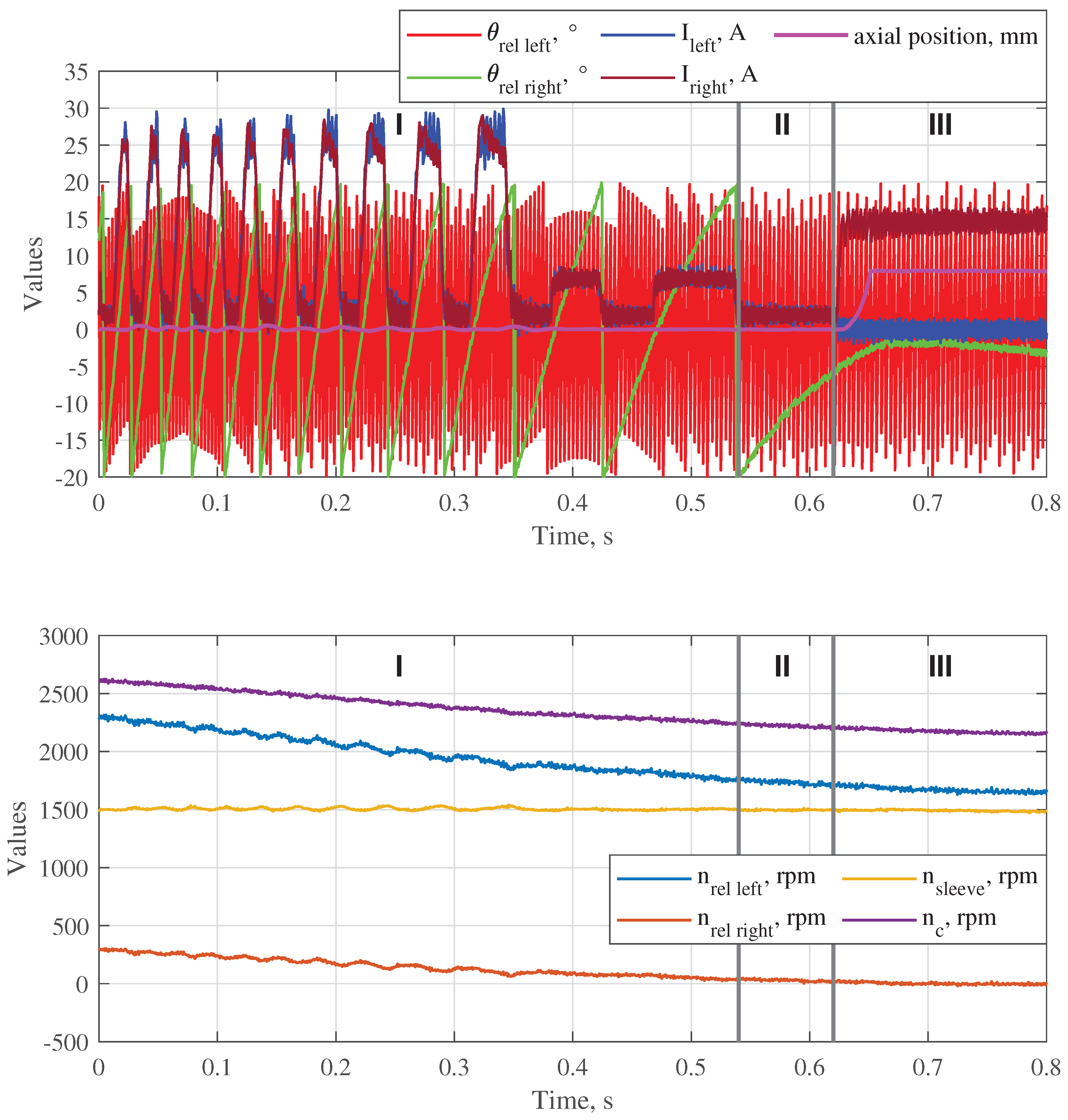
Finally, Figure 15 shows the situation when the output shaft rotates at a speed of 1500 rpm, the initial is 300 rpm, and the right gear has to be shifted. The relative speeds on the sides are very different in this case, since the initial is 2308 rpm. Motor 2 was turned off, and the synchronizing torque was applied on the right side to decelerate the right shaft. The friction torque and the actuator torque have the same direction in this case. After became app. equal to 80 rpm, the synchronizing current was strongly reduced, otherwise would became negative at the end of the next current pulse, which must be avoided. At the lower , the adjustment of the coil currents depending on was no longer required, and the residual force difference was compensated by the spring-loaded balls. The right gear was shifted when became lower than 30 rpm at = −6°, so that the teeth were engaged with the slots without the face contact phase (no intermediate stop of the axial motion at x = 5 mm) at unaligned angular positions.
6. Conclusions
The LREA presented earlier in [40] was modified to allow its application as a double-sided dog clutch in automotive gearboxes. In contrast to common dog clutches, the developed double-sided clutch demonstrates the possibility of the rotation speed synchronization without an external torque source, while its design remains simple and reliable. The actuator can be integrated between two gearwheels of a gearbox. The speed difference is reduced electromagnetically without mechanical contact between the parts, which is a big advantage comparing to common synchronizers.
In rotary operation, the electromagnetic torque generated by the LREA reduces the initial speed difference to a small positive value, which is than used to reach the relative angle between the teeth of the sleeve and the slots of its counterpart where a direct teeth engagement is possible. In linear operation, the selected gear can be engaged or disengaged using the axial reluctance force generated by the LREA. Shifting of non-neutral gears starts at the relative angle reached in the rotary operation, so that the teeth are directly engaged. Thus, an axial contact of the teeth at unaligned positions, which can lead to unsuccessful shifting, is avoided.
A special control algorithm developed for rotary operation allows the compensation of the axial force which arises during the speed synchronization by a simultaneous excitation of the coil on the opposite side and adjustment of the coil currents depending on the corresponding relative angle. Thus, the shift sleeve remains in neutral gear until the appropriate shifting conditions are reached. The synchronizing torque is always generated on the side with a lower speed difference, which is named as synchronizing side, while the opposite is named as compensating side and creates the balance of the axial forces. The average value of the collateral torque on the compensating side is approximately zero. The sides can be switched during the synchronization depending on their relative speeds. The time of the current rise/fall is taken into account to adjust the excitation angles. The residual force difference can be compensated by the spring-loaded balls placed under the shift sleeve. At lower currents, the current adjustment is not required since the force changes slightly with the change of the relative angle. The voltages are applied to the coils based on the difference between the required and measured currents using a simple control method common for reluctance machines.
Since the gearwheels have different sizes and are interlocked with the same countershaft, the resulting friction torque is always higher on the bigger gearwheel. It makes its acceleration more difficult comparing to the smaller gearwheel. The actuator must be able to generate an average torque that is higher than the resulting friction torque to accelerate the gearwheel, while its braking is always possible since the actuator torque and the friction torque work in the same direction. The simulations show that, in principle, positive and negative speed differences can be reduced by the electromagnetic torque of the actuator while the shift sleeve remains in neutral gear. Moreover, a direct engagement of the teeth with the slots during gear shifting is possible on both sides.
To verify the theoretical results, a prototype of the double-sided dog clutch and a testing gearbox were designed and manufactured. The assembled gearbox with the integrated clutch was installed on a testrig with two motors, which can rotate the output shaft and the countershaft at different speeds. The experimental results show that the average electromagnetic torque generated by the actuator strongly reduces with the increase of the relative speed on the synchronizing side. This problem can be solved if the coils will be supplied with a higher voltage (the maximum voltage was limited to 70 V by the available electronic control unit). Further, pre-synchronized gear shifting was tested experimentally for both gears. Negative and positive differences between the rotation speed of the gearwheel and the shift sleeve could be reduced by the actuator without a significant displacement of the shift sleeve from the central position. In all four cases, the required gear was shifted without an axial contact between the shift sleeve and the corresponding complementary ring at unengaged state.
In the following publications, we will present algorithms that can make sensorless operation of the clutch possible.
7. Patents
Miroschnitschenko, B.; Polschak, F.; Rafetseder, D. Electromechanical clutch and method for closing and opening an electromechanical clutch and for sensorless determination of the relative angular velocity of a first and second shaft. DE102022121714A1, February 2024.
Author Contributions
Bogdan Miroschnitschenko: conceptualization, theoretical analysis, software, experimental validation, writing—original draft preparation; Florian Poltschak: project administration, funding acquisition, writing—review and editing, supervision; Wolfgang Amrhein: writing—review and editing, supervision. All authors have read and agreed to the published version of the manuscript.
Funding
This research was funded by Hoerbiger Foundation, Zug, Switzerland.
Data Availability Statement
‘Conventional shifting 300 rpm‘ — the video shows conventional gear shifting process with a dog clutch: left gear is shifted from the neutral gear at the presented speed difference 300 rpm exciting the left coil. It can be seen that the safety coupling is released due to the overload caused by the unsynchronized relative speed. Shifting is unsuccessful since the teeth are not engaged with the slots due to their unaligned position. The shift sleeve moves back and collides with the right complementary ring after the left coil is de-excited. After that, the sleeve remains disengaged. ‘Shifting with the developed clutch 300 rpm‘ — the video shows gear shifting process using the advantages of the developed clutch: the presented speed difference 300 rpm is pre-synchronized, after that, the sleeve teeth are engaged with the slots of the complementary ring. The first axial impact between the sleeve teeth and the side surface of the ring at the unaligned relative angle is avoided (only one impact can be heard at the end of engagement). The gear is successfully shifted. Moreover, the speed synchronization makes the shifting process smooth (the impact force is much lower, no overload of the safety coupling.)
Acknowledgments
The authors express gratitude to Hoerbiger Drive Technology Holding GmbH, especially to Benjamin Haslach for providing the mechanical parts of the testing gearbox, and to Gerhard Strasser from Institute of Electric Drives and Power Electronics, Johannes Kepler University Linz for his assistance in assembling the testrig.
Conflicts of Interest
The authors declare no conflicts of interest. The funders had no role in the design of the study; in the collection, analysis, or interpretation of data; in the writing of the manuscript. The funders have allowed to publish the results.
Abbreviations
The following abbreviations are used in this manuscript:
| LREA | Linear-rotary electromagnetic actuator |
| PMs | Permanent magnets |
| NTC | Negative temperature coefficient |
| ECU | Electronic control unit |
References
- Wang, Z.; Qu, X.; Cai, Q.; Chu, F.; Wang, J.; Shi, D. Efficiency Analysis of Electric Vehicles with AMT and Dual-Motor Systems. World Electric Vehicle Journal 2024, 15, 182. [Google Scholar] [CrossRef]
- Tian, Y.; Zhang, N.; Zhou, S.; Walker, P.D. Model and gear shifting control of a novel two-speed transmission for battery electric vehicles. Mechanism and Machine Theory 2020, 152, 103902. [Google Scholar] [CrossRef]
- Jeong, W.; Han, J.; Kim, T.; Lee, J.; Oh, S. Two-speed transmission structure and optimization design for electric vehicles. Machines 2023, 12, 9. [Google Scholar] [CrossRef]
- Piracha, M.Z.; Grauers, A.; Hellsing, J. Time optimal control of gearbox synchronizers for minimizing noise and wear. In Proceedings of the 2020 IEEE Conference on Control Technology and Applications (CCTA). IEEE, 2020, pp. 573–580.
- Barathiraja, K.; Devaradjane, G.; Paul, J.; Rakesh, S.; Jamadade, G. Analysis of automotive transmission gearbox synchronizer wear due to torsional vibration and the parameters influencing wear reduction. Engineering Failure Analysis 2019, 105, 427–443. [Google Scholar]
- Wang, Y.; Wu, J.; Zhang, N.; Mo, W. Dynamics modeling and shift control of a novel spring-based synchronizer for electric vehicles. Mechanism and Machine Theory 2022, 168, 104586. [Google Scholar] [CrossRef]
- Pan, T.; Zang, H.; Wu, P. Hierarchical mode optimization strategy for gear engagement process of automated manual transmission with electromagnetic actuator. Proceedings of the Institution of Mechanical Engineers, Part D: Journal of Automobile Engineering 2023, 237, 913–929. [Google Scholar] [CrossRef]
- Gongye, X.; Du, C.; Li, L.; Huang, C.; Wang, J.; Dai, Z. Research on Precise Tracking Control of Gear-Shifting Actuator for Non-Synchronizer Automatic Mechanical Transmission Based on Sleeve Trajectory Planning. Energies 2024, 17, 1092. [Google Scholar] [CrossRef]
- Stetter, R.; Göser, R.; Gresser, S.; Witczak, M.; Till, M. Fault-Tolerant Design of a Gear Shifting System for Autonomous Driving. In Proceedings of the Proceedings of the Design Society: DESIGN Conference. Cambridge University Press, 2020, Vol. 1, pp. 1125–1134.
- Achtenová, G.; Pakosta, J.; El Morsy, M. Smoothness of maybach dog clutch shift in the automotive gearbox. In Proceedings of the 13th International CTI Symposium, Berlin, 2014.
- Bóka, G.; Márialigeti, J.; Lovas, L.; Trencséni, B. Face dog clutch engagement at low mismatch speed. Periodica Polytechnica Transportation Engineering 2010, 38, 29–35. [Google Scholar] [CrossRef]
- Bóka, G.; Lovas, L.; Márialigeti, J.; Trencséni, B. Engagement capability of face-dog clutches on heavy duty automated mechanical transmissions with transmission brake. Proceedings of the Institution of Mechanical Engineers, Part D: Journal of Automobile Engineering 2010, 224, 1125–1139. [Google Scholar] [CrossRef]
- Bóka, G. Shifting optimization of face dog clutches in heavy duty automated mechanical transmissions. PhD thesis, Budapest University of Technology and Economics (Hungary), 2011.
- Aljawabrah, A.; Lovas, L. Study the effect of the tooth chamfer angle on the dog clutch shiftability. Design of Machines and Structures 2023, 13, 11–23. [Google Scholar] [CrossRef]
- Aljawabrah, A.; Lovas, L. Sensitivity analysis of dog clutch shiftability to system parameters. International Review of Applied Sciences and Engineering 2024, 15, 61–72. [Google Scholar] [CrossRef]
- Aljawabrah, A. Analysis and Control of the Gearshift Process Based on a Dog Clutch Shiftability Model. Cognitive Sustainability 2024, 3. [Google Scholar] [CrossRef]
- Poltschak, F.; Rafetseder, D. Completely integrated electromagnetic dog clutch actuator for automotive applications. In Proceedings of the IKMT 2022; 13. GMM/ETG-Symposium. VDE, 2022, pp. 1–6.
- Lu, Z.; Chen, H.; Wang, L.; Zeng, Y.; Ren, X.; Li, K.; Tian, G. Gear-shifting control of non-synchronizer electric-driven mechanical transmission with active angle alignment. Optimal Control Applications and Methods 2022, 43, 322–338. [Google Scholar] [CrossRef]
- Lu, Z.; Tian, G. Time-optimal coordination gear-shifting control with a rotational angle difference estimation and alignment algorithm in the vehicle-start condition. IEEE Transactions on Transportation Electrification 2024, 10, 9000–9015. [Google Scholar] [CrossRef]
- Gongye, X.; Du, C.; Huang, C.; Huang, J.; Wang, J. Research on gearshift of Non-synchronizer automatic mechanical transmission based on hierarchical bounding box collision detection algorithm. Energy Reports 2025, 13, 1200–1214. [Google Scholar] [CrossRef]
- Yang, L.; Park, D.; Lyu, S.; Zheng, C.; Kim, N. Optimal control for shifting command of two-speed electric vehicles considering shifting loss. International Journal of Automotive Technology 2023, 24, 1051–1059. [Google Scholar] [CrossRef]
- Lin, S.; Li, B. Shift force optimization and trajectory tracking control for a novel gearshift system equipped with electromagnetic linear actuators. IEEE/ASME Transactions on Mechatronics 2019, 24, 1640–1650. [Google Scholar] [CrossRef]
- Poltschak, F.; Rafetseder, D.; Miroschnitschenko, B. Electromagnetic direct drives for positive mechanical engagement in the automotive drivetrain. In Proceedings of the Tagungshandbuch Symposium Elektromagnetismus, 2025, pp. 93–100.
- Baraszu, R.; Cikanek, S. Torque fill-in for an automated shift manual transmission in a parallel hybrid electric vehicle. In Proceedings of the Proceedings of the 2002 American Control Conference, 2002, Vol. 2, pp. 1431–1436.
- De Pinto, S.; Camocardi, P.; Sorniotti, A.; Gruber, P.; Perlo, P.; Viotto, F. Torque-Fill Control and Energy Management for a Four-Wheel-Drive Electric Vehicle Layout With Two-Speed Transmissions. IEEE Transactions on Industry Applications 2017, 53, 447–458. [Google Scholar] [CrossRef]
- Park, G.; Park, J.; Kum, D. Preview control of dog clutch-based electric vehicle transmission via dynamic programming: proof of concept. In Proceedings of the 2022 IEEE Conference on Control Technology and Applications (CCTA). IEEE, 2022, pp. 683–690.
- Park, G.; Choi, K.; Kum, D. Predictive Control of a Dog-clutch Transmission via a Transformer-based Velocity Prediction. IEEE Transactions on Vehicular Technology 2024. [Google Scholar] [CrossRef]
- Walker, P.D.; Zhang, N.; Tamba, R. Control of gear shifts in dual clutch transmission powertrains. Mechanical Systems and Signal Processing 2011, 25, 1923–1936. [Google Scholar] [CrossRef]
- Glielmo, L.; Iannelli, L.; Vacca, V.; Vasca, F. Gearshift control for automated manual transmissions. IEEE/ASME transactions on mechatronics 2006, 11, 17–26. [Google Scholar] [CrossRef]
- Wanli, X.; Wei, Z.; Bin, S.; Ximeng, X. Investigation of manual transmission synchronizer failure mechanism induced by interface material/lubricant combinations. Wear 2015, 328, 475–479. [Google Scholar] [CrossRef]
- Turner, A.; Ramsay, K.; Clark, R.; Howe, D. Direct-drive rotary-linear electromechanical actuation system for control of gearshifts in automated transmissions. In Proceedings of the 2007 IEEE Vehicle Power and Propulsion Conference. IEEE, 2007, pp. 267–272.
- Krebs, G.; Tounzi, A.; Pauwels, B.; Willemot, D.; Piriou, F. Modeling of a linear and rotary permanent magnet actuator. IEEE Transactions on Magnetics 2008, 44, 4357–4360. [Google Scholar] [CrossRef]
- Jin, P.; Fang, S.; Lin, H.; Wang, X.; Zhou, S. A novel linear and rotary Halbach permanent magnet actuator with two degrees-of-freedom. Journal of Applied Physics 2012, 111, 07E725. [Google Scholar] [CrossRef]
- Jin, P.; Yuan, Y.; Jian, G.; Lin, H.; Fang, S.; Yang, H. Static characteristics of novel air-cored linear and rotary Halbach permanent magnet actuator. IEEE transactions on magnetics 2014, 50, 977–980. [Google Scholar] [CrossRef]
- Guo, K.; Fang, S.; Yang, H.; Lin, H.; Ho, S.L. A novel linear-rotary permanent-magnet actuator using interlaced poles. IEEE Transactions on Magnetics 2015, 51, 1–4. [Google Scholar]
- Mirić, S.; Tüysüz, A.; Kolar, J.W. Comparative evaluation of linear-rotary actuator topologies for highly dynamic applications. In Proceedings of the 2017 IEEE International Electric Machines and Drives Conference (IEMDC). IEEE, 2017, pp. 1–7.
- Denkena, B.; Ahlborn, P. Linear-rotary direct drive for multi-functional machine tools. CIRP Annals 2022, 71, 349–352. [Google Scholar] [CrossRef]
- Szabó, L.; Benţia, I.; Ruba, M. A rotary-linear switched reluctance motor for automotive applications. In Proceedings of the 2012 XXth International Conference on Electrical Machines. IEEE, 2012, pp. 2615–2621.
- Nezamabadi, M.M.; Afjei, E.; Torkaman, H. Design, dynamic electromagnetic analysis, FEM, and fabrication of a new switched-reluctance motor with hybrid motion. IEEE Transactions on Magnetics 2015, 52, 1–8. [Google Scholar] [CrossRef]
- Miroschnitschenko, B. Magnetic flux calculation in a novel linear-rotary electromagnetic actuator using 3d magnetic equivalent circuit. In Proceedings of the 2023 11th International Conference on Control, Mechatronics and Automation (ICCMA). IEEE, 2023, pp. 336–345.
- Miroschnitschenko, B.; Amrhein, W.; Poltschak, F. Design and Optimization of a Linear-Rotary Electromagnetic Actuator Based on Analytical Model of Magnetic Flux. In Proceedings of the 2024 International Symposium on Power Electronics, Electrical Drives, Automation and Motion (SPEEDAM). IEEE, 2024, pp. 1002–1009.
- Miroschnitschenko, B.; Polschak, F.; Rafetseder, D. Electromechanical clutch and method for closing and opening an electromechanical clutch and for sensorless determination of the relative angular velocity of a first and second shaft. DE102022121714A1, February 2024.
- Tsai, M.C.; Huang, C.C.; Huang, Z.Y. A new two-phase homopolar switched reluctance motor for electric vehicle applications. Journal of magnetism and magnetic materials 2003, 267, 173–181. [Google Scholar] [CrossRef]
- Buhmann, M.D. Radial basis functions: theory and implementations; Vol. 12, Cambridge university press, 2003.
- Miller, T.J.E. Electronic control of switched reluctance machines; Elsevier, 2001.
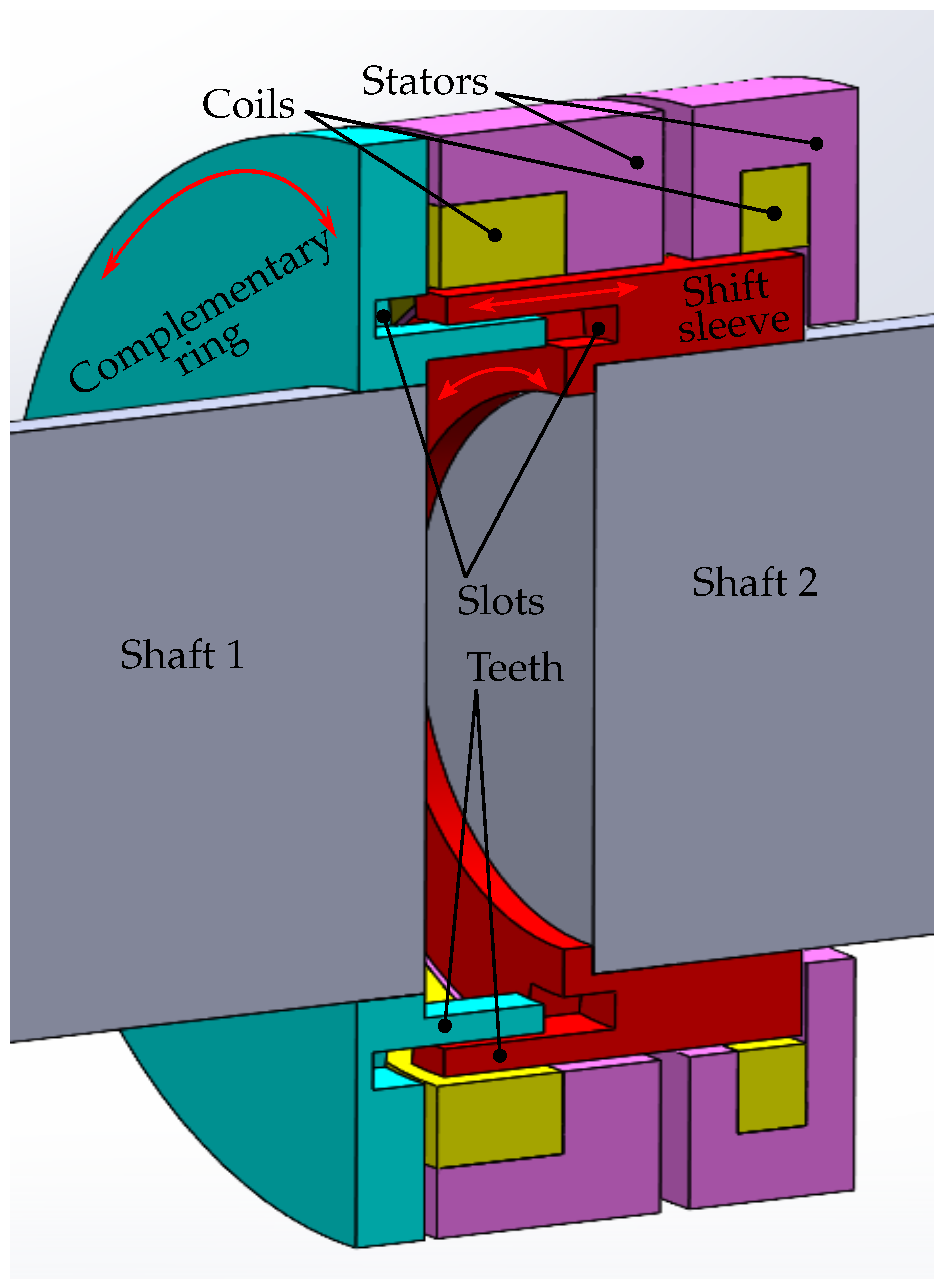
Figure 2.
Novel double-sided dog clutch for gearbox applications.
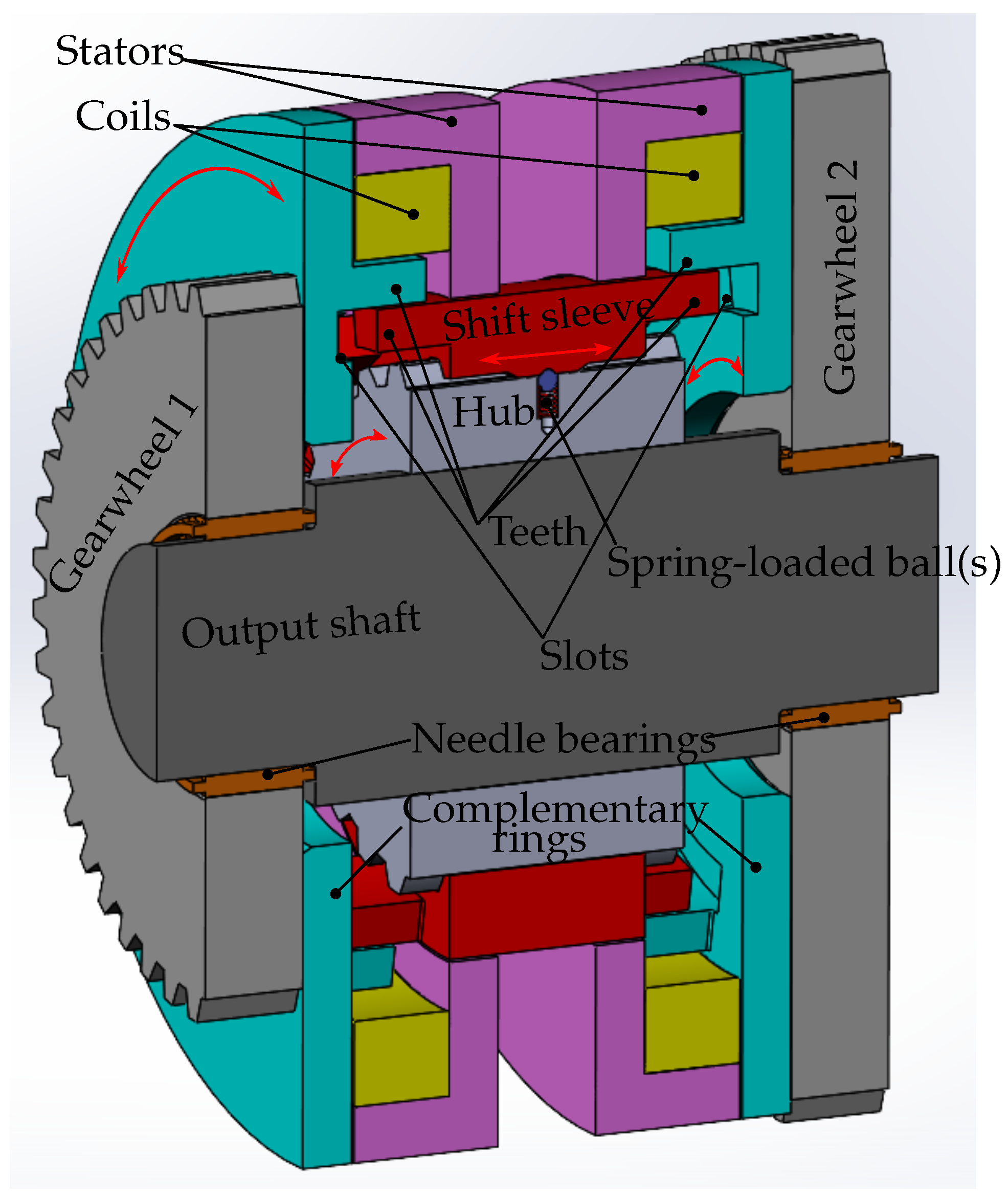
Figure 3.
Electromagnetic torque and force generated by each side of the actuator at the central axial position of the shift sleeve (x = 0) depending on the coil current and relative angular position on the side.
Figure 3.
Electromagnetic torque and force generated by each side of the actuator at the central axial position of the shift sleeve (x = 0) depending on the coil current and relative angular position on the side.
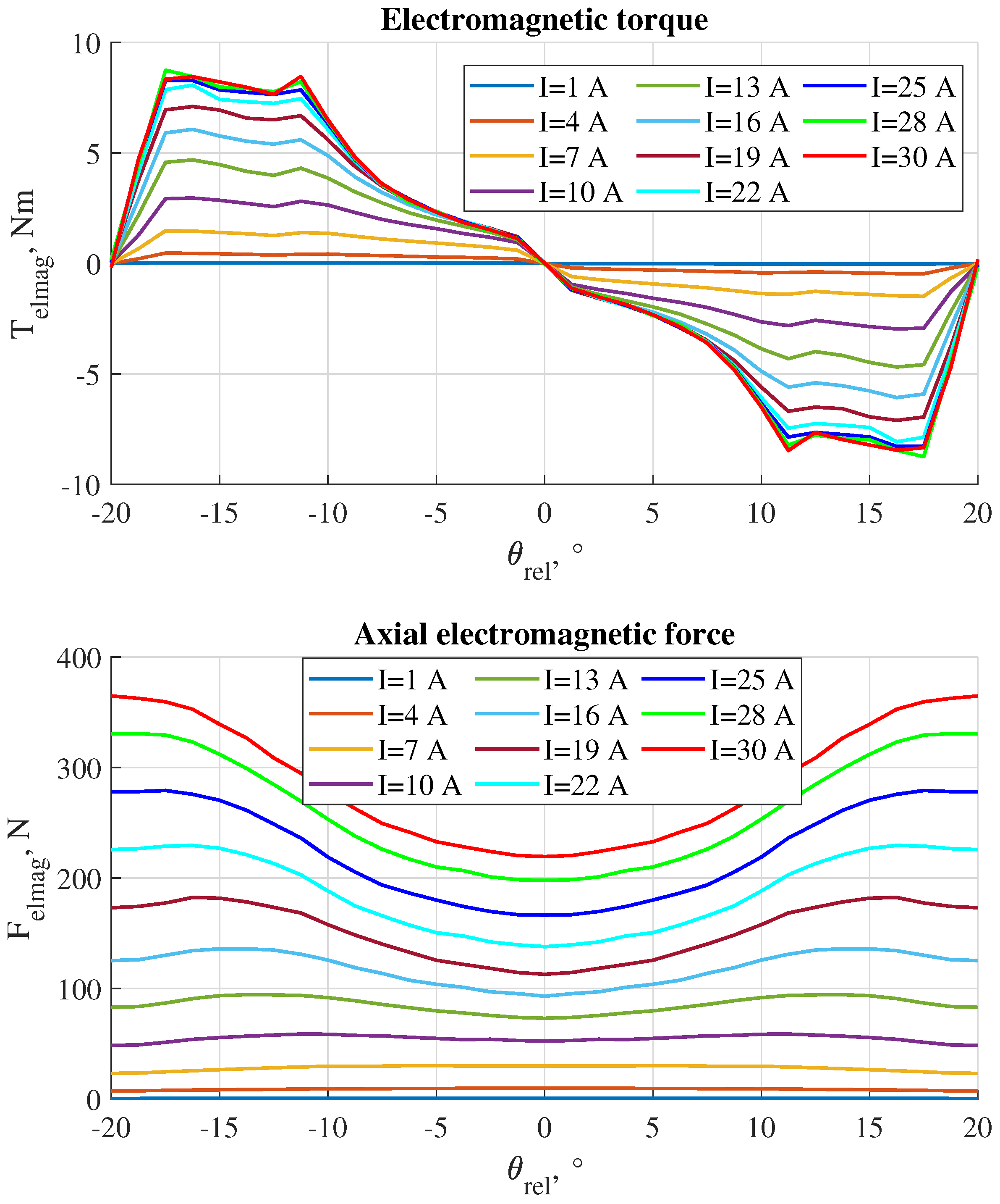
Figure 4.
Current control matrix based on the inverted force characteristic (x=0).

Figure 5.
Control algorithm for the speed synchronization.
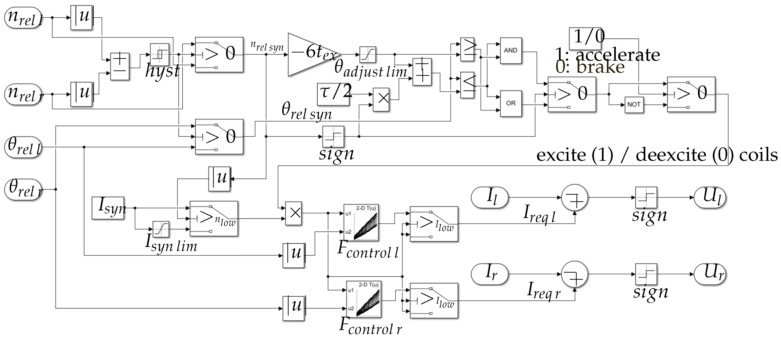
Figure 6.
Simulated results of left gear shifting with a preliminary reduction of the rotation speed difference and direct teeth-slots engagement.
Figure 6.
Simulated results of left gear shifting with a preliminary reduction of the rotation speed difference and direct teeth-slots engagement.
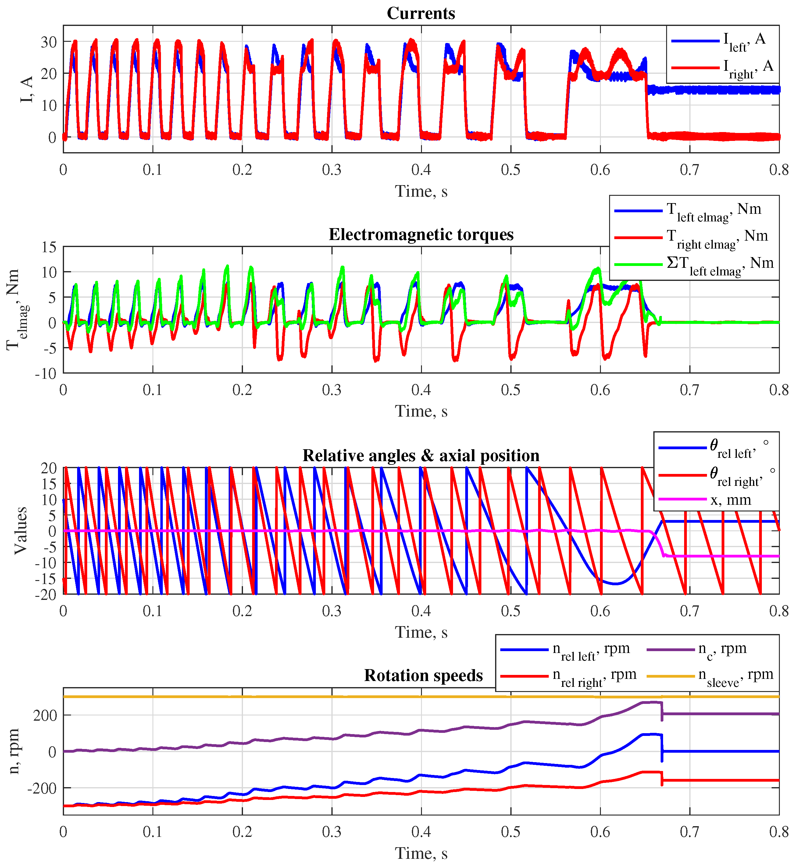
Figure 7.
Simulated results of right gear shifting with a preliminary reduction of the rotation speed difference and direct teeth-slots engagement.
Figure 7.
Simulated results of right gear shifting with a preliminary reduction of the rotation speed difference and direct teeth-slots engagement.
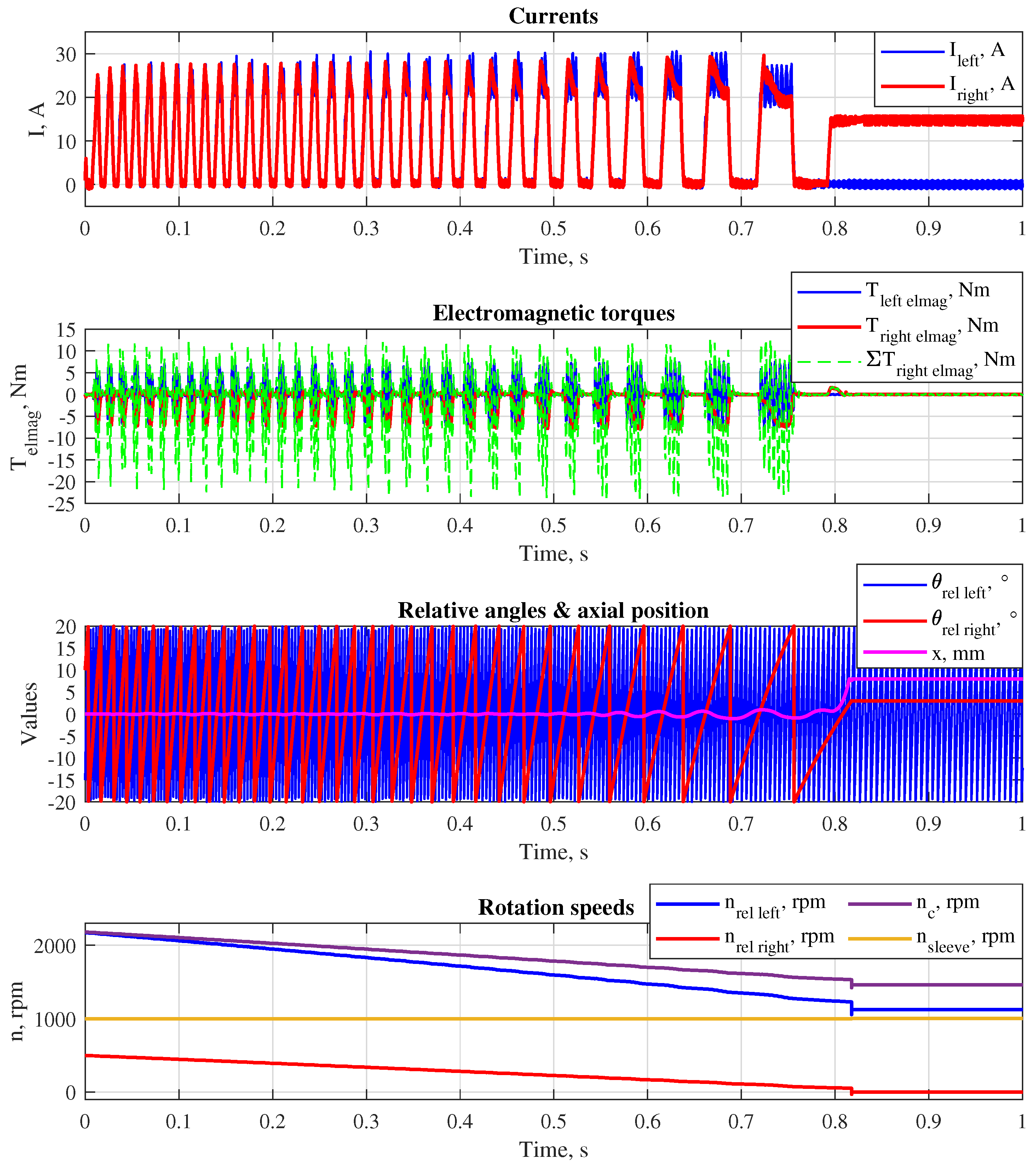
Figure 8.
Testing gearbox with the clutch prototype.
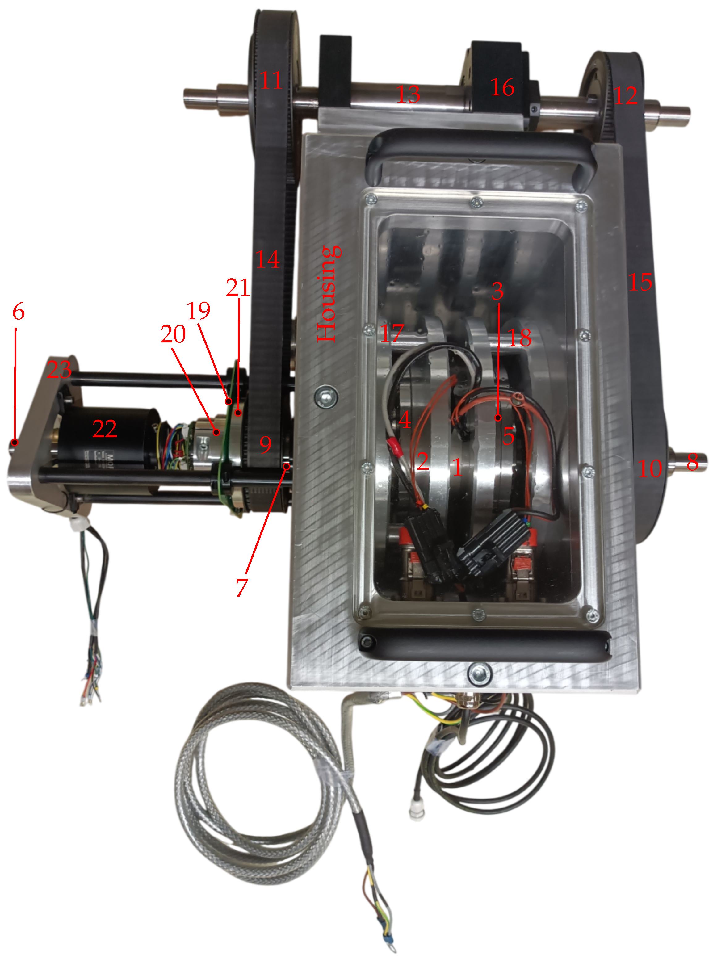
Figure 9.
Testrig with installed gearbox.
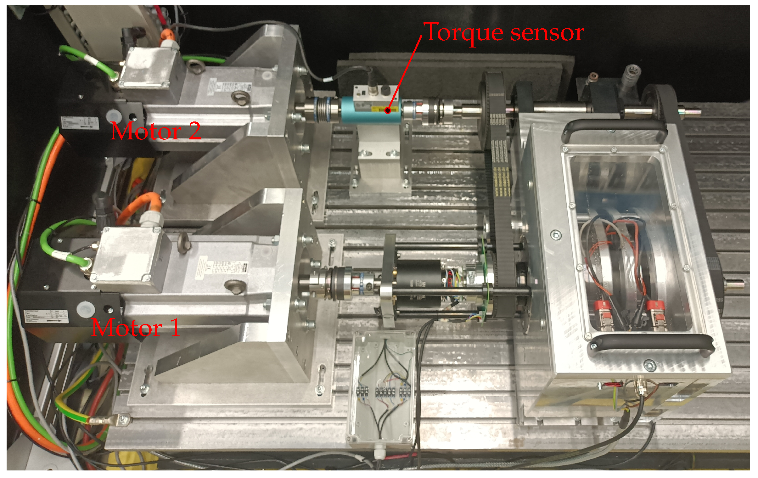
Figure 10.
Torque measured on the countershaft (motor 1 is controlled to rotate at rpm, motor 2 generates torque to keep = 0, the left and the right complementary rings are aligned relative to each other - both actuator sides generate the same ).
Figure 10.
Torque measured on the countershaft (motor 1 is controlled to rotate at rpm, motor 2 generates torque to keep = 0, the left and the right complementary rings are aligned relative to each other - both actuator sides generate the same ).
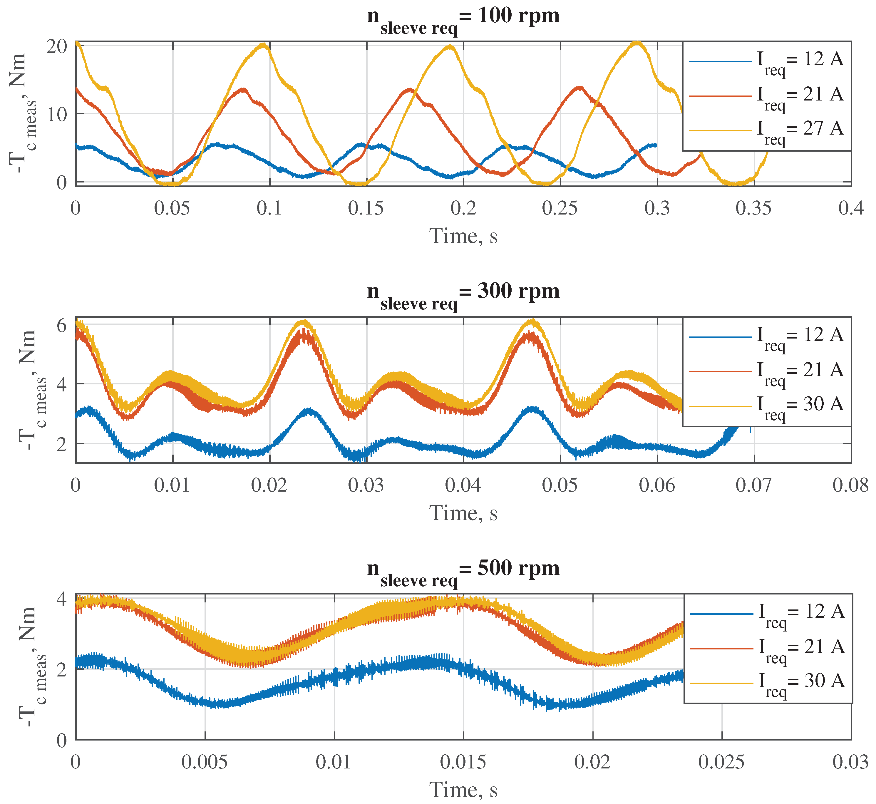
Figure 11.
Absolute value of mean torque generated by the actuator depending on the speed difference and required excitation current on the synchronized side.
Figure 11.
Absolute value of mean torque generated by the actuator depending on the speed difference and required excitation current on the synchronized side.
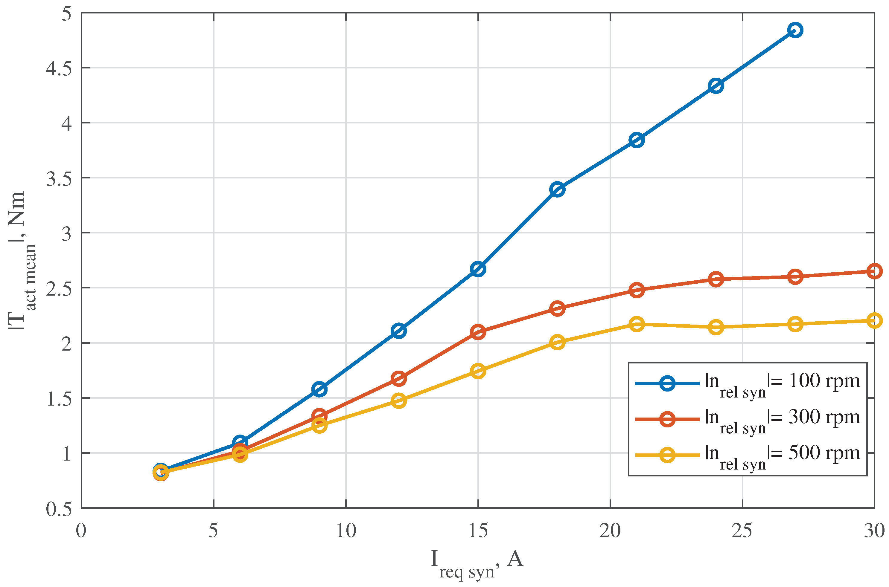
Figure 12.
Experimental results of left gear shifting ( = 300 rpm, = −300 rpm): I - synchronization of the rotation speeds; II - reduction of the residual angle difference; III - engagement of the shift sleeve.
Figure 12.
Experimental results of left gear shifting ( = 300 rpm, = −300 rpm): I - synchronization of the rotation speeds; II - reduction of the residual angle difference; III - engagement of the shift sleeve.
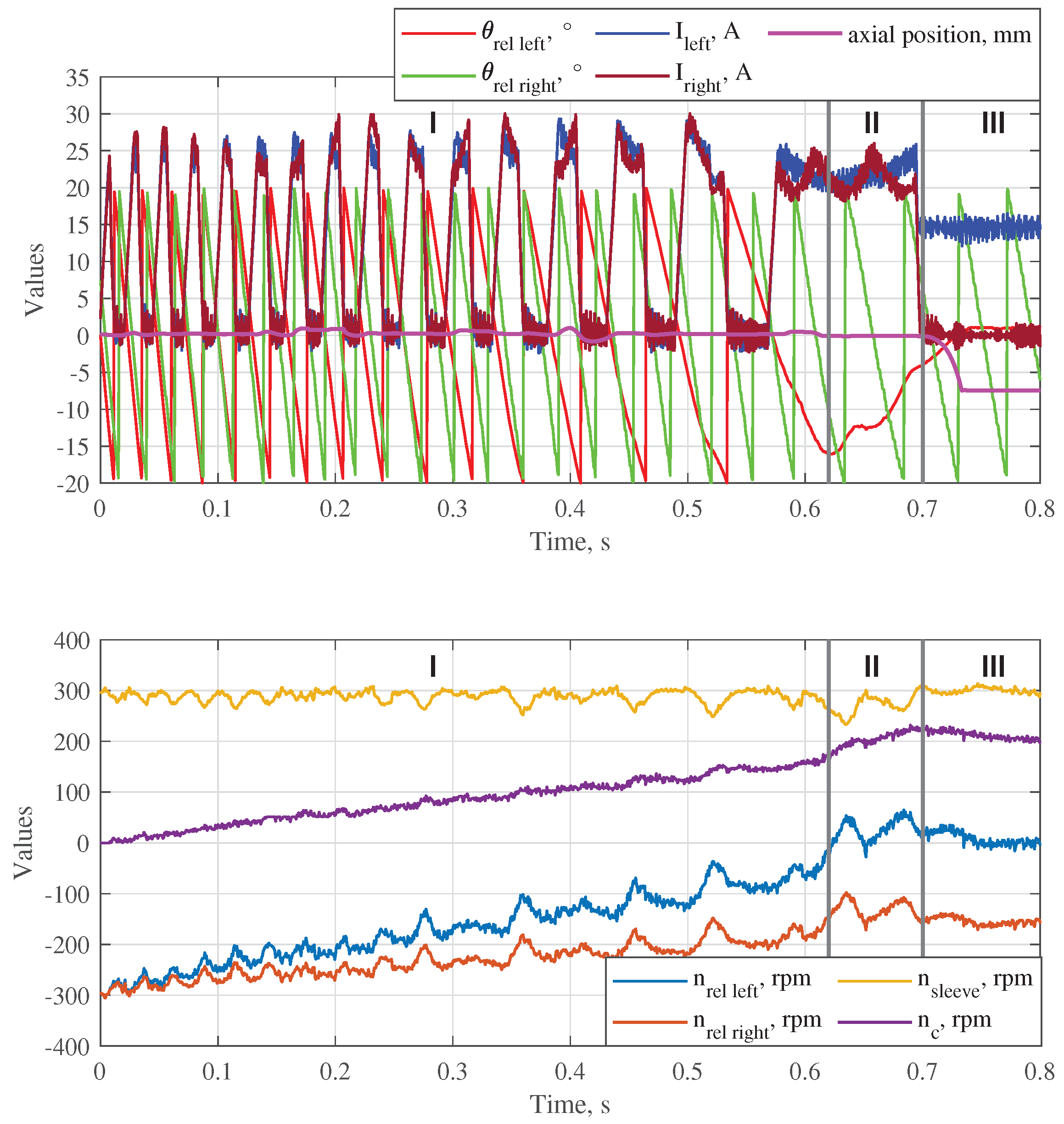
Figure 13.
Experimental results of left gear shifting ( = 500 rpm, = 500 rpm): I - synchronization of the rotation speeds; II - reduction of the residual angle difference; III - engagement of the shift sleeve.
Figure 13.
Experimental results of left gear shifting ( = 500 rpm, = 500 rpm): I - synchronization of the rotation speeds; II - reduction of the residual angle difference; III - engagement of the shift sleeve.
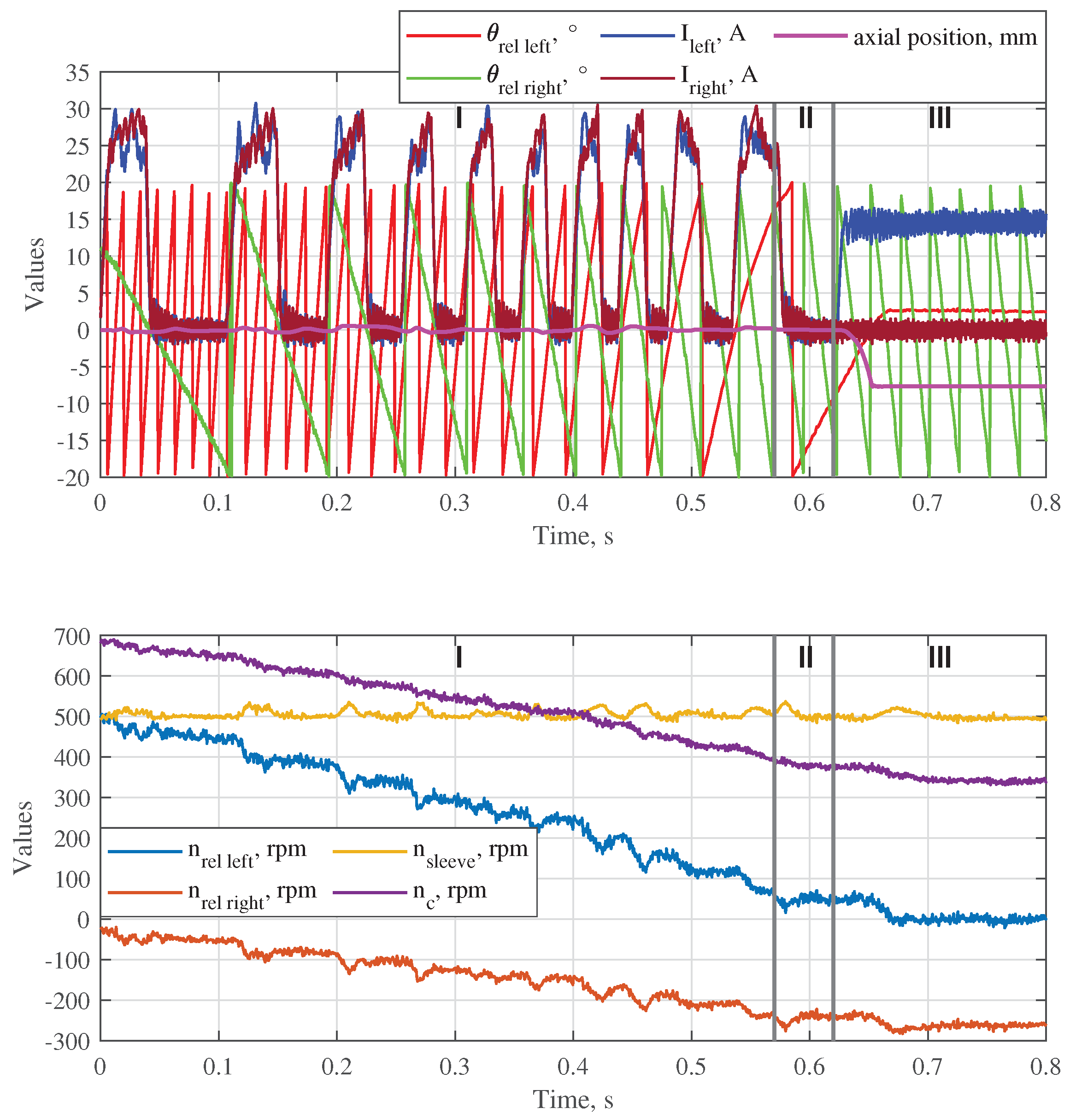
Figure 14.
Experimental results of right gear shifting ( = 1000 rpm, = −300 rpm): I - synchronization of the rotation speeds; II - reduction of the residual angle difference; III - engagement of the shift sleeve.
Figure 14.
Experimental results of right gear shifting ( = 1000 rpm, = −300 rpm): I - synchronization of the rotation speeds; II - reduction of the residual angle difference; III - engagement of the shift sleeve.
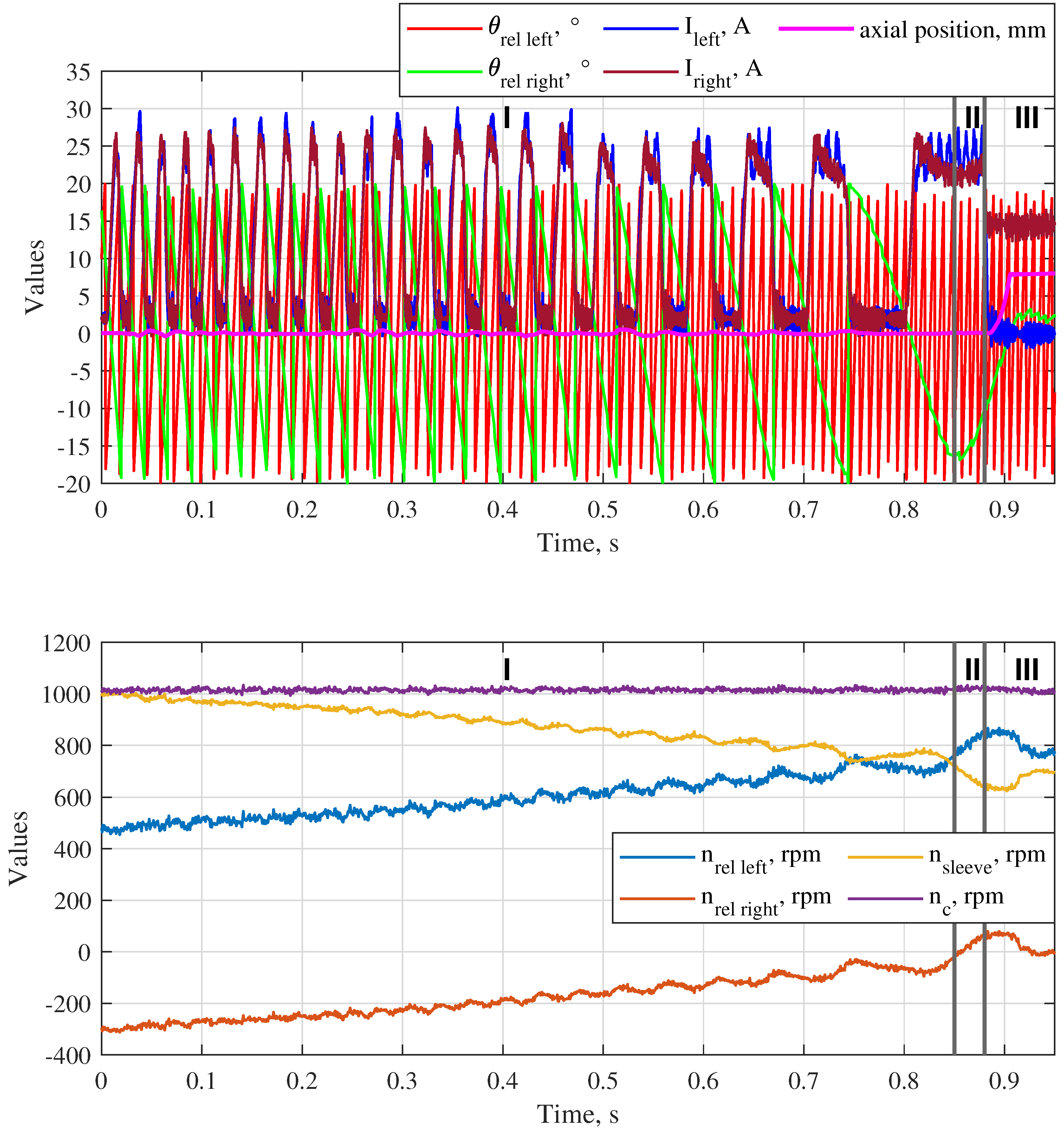
Figure 15.
Experimental results of right gear shifting ( = 1500 rpm, = 300 rpm): I - synchronization of the rotation speeds; II - reduction of the residual angle difference; III - engagement of the shift sleeve.
Figure 15.
Experimental results of right gear shifting ( = 1500 rpm, = 300 rpm): I - synchronization of the rotation speeds; II - reduction of the residual angle difference; III - engagement of the shift sleeve.
Disclaimer/Publisher’s Note: The statements, opinions and data contained in all publications are solely those of the individual author(s) and contributor(s) and not of MDPI and/or the editor(s). MDPI and/or the editor(s) disclaim responsibility for any injury to people or property resulting from any ideas, methods, instructions or products referred to in the content. |
© 2025 by the authors. Licensee MDPI, Basel, Switzerland. This article is an open access article distributed under the terms and conditions of the Creative Commons Attribution (CC BY) license (http://creativecommons.org/licenses/by/4.0/).
Copyright: This open access article is published under a Creative Commons CC BY 4.0 license, which permit the free download, distribution, and reuse, provided that the author and preprint are cited in any reuse.


