
Submitted:
30 April 2025
Posted:
12 May 2025
You are already at the latest version
Abstract
Limited battery life compromises the usability of inspection and operation robots in hazardous environments such as nuclear sites under decommissioning. Both manually replacing the batteries and installing of charging bays may be infeasible. Inductive wireless power transfer is a possible solution to deliver power through barriers such as reinforced concrete walls without physical contact. However, when requiring decent power (e.g. 100 W) to be transmitted over longer distances, the exaggerated dimensions of transmitting and receiving coils restrained the integrations with mobile robots. In this paper, a novel retractable design of the coil used in an inductive wireless power charging system is proposed, proving the minor deformation of the winding shape does not affect transmission efficiency. A prototype with 5x size compression is implemented and tested. It successfully transmitted 116.5 W over a distance of 1 m with 68.72% energy efficiency. The principle can be applied to a wide range of mobile platforms with limited payload area where remote power is needed.
Keywords:
magnetic resonant coupling inductive
; wireless power transfer
; mid-sized mobile robots
; mechatronics
1. Introduction
The use of mobile robots is on the rise, and as tasks increasingly require mobility beyond the constraints of a fixed workspace, there is growth in demand for deployment [1]. This can be observed from the development of various types of mobile robots on the ground, in the air, and underwater. Several application domains for such mobile robots include oil and gas refinery inspection [2], radiation mapping [3,4], underwater mapping [5,6], and nuclear-decommissioning [7,8].
The main constraint for long-term mobile robot deployment is the onboard battery capacity, especially in scenarios where robots operate behind sturdy concrete walls [1]. As a result, the only options are to return to the charging station for recharging or to perform manual battery replacement on-site [1]. These two options only address the battery capacity limitations of mobile robots, though they result in increased downtime. The other option is to use a tether to control the mobile robot. However, this approach has additional difficulties such as tether crossover, restrictions on bending around obstacles, and a decrease in the payload of the mobile robot from the tether system, all of which restrict the mobile robots’ performance and mobility [9]. Alternatively, wireless power transfer (WPT) could be a suitable option.
In terms of power rating, the common implementation of WPT on mobile robots is mainly concentrated on high-power applications (kW) such as electrical vehicles which generally operate with a transmission distance of less than 0.3 m or low-power applications such as consumer electronic devices within centimetre distances [10], wireless sensor network (WSN) at kilometre distances [11] and medical implants at centimetre distances. WPT technologies limitations and the implementation for mobile robots with mid-power range and transmission distances of from 1 m up to 20 m have been discussed in [1].
The source of power for these mobile robots is usually lithium batteries which can generally last for 30 minutes up to 8 hours at most depending on the usage [12]. Mobile robots are typically equipped with a set of payloads such as sensors, cameras, positioning systems and other necessary equipment designed for the assignment completion [13]. Therefore, increasing the number of onboard batteries in mobile robots often presents challenges related to space constraints and weight limitations.
Table 1 shows the summary of parameters on the robot’s power and battery requirements where P is the power consumption, T is the operational time with the battery energy (), t is the robot’s charging time and W represents the maximum payload of each robot. Husky and ANYmal are ground-based robots (UGV), Hydrus-300 and BlueROV represent autonomous underwater vehicles (AUV), while Phantom 4 and Matrice 300 are examples of unmanned aerial vehicles (UAV). The average power requirement for these mobile platforms is 100 W to 200 W, with an average operational time of 2.5 hours based on battery capacity.
Despite the wireless power transfer technology promisingly delivering the power needed by the robots at the expected distance, there is an unresolved compromise among the giant sizes of coils, energy efficiency, and distance. A prior work [18] facilitates an octagon-shaped coil frame with a 1-meter aperture diameter. It is capable of transmitting 109.7 W over a 1-meter distance with 47.14% energy efficiency, as shown in Figure 1. Although the primary objective is achieved, the design size is impractical to implement onto a mobile platform in real applications. This paper addresses the space and payload constraints by introducing a robust and compact retractable WPT coil frame. We have enumerated a range of retractable mechanisms, with considerations of minimizing the number of actuators, shortlisted possible solutions and selected the optimal solution for the anticipated applications. The final design of the receiving coil is not of a rigid, regular shape however the theoretical and practical verifications proved it does provide a sufficient amount of required power for a mid-range mobile platform. Figure 2 is the schematic illustration depicting the IPT transmitter and receiver regular polygon coils compared to irregular shape coils.
The following parts of the paper are organised as: Section 2 presents the specification requirements for the coil designs. Section 3 elaborates the WPT system’s principles and shows the capability of power transfer performance with the iterations of coil geometry. Section 4 details the analysis of the WPT system modelling and Section 5 analyses the mechatronic design selection. Section 6 discusses the experimental setup, Section 7 consists of the results and discussions, and Section 8 concludes the study and sets the outlook for the future work.
2. Specification Requirement
The general objective of designing the retractable coil structure is based on the assumptions of 1. The equivalent aperture area is similar. This is due to the nature of the magnetic field coupling mechanism; 2. the thickness of the wires used remains the same so that the level of power transmitted, the energy efficiency and the transmission distance are unaffected. The technical requirements are evaluated using a weighted decision matrix while maintaining the parameters used in the octagon-coil WPT system in [18] (1 m circumcircle radius, 8 spokes, 5 turns, 0.75 mm cross-sectional radius coil). The overall score of the functions required by the design is determined using a five-level scale, which is divided into three categories:
- Reconfigurability: represents the complexity of expansion-to-compression of the design. The design is rated from 1 to 5 where 1 is the low complexity and 5 is the high mechanical complexity which contributes to the coil reconfiguring process.
- Coil Management: assesses the WPT coil management in terms of storage while the design is in a fully compressed position and coil handling during the expansion process (1 being less likely to tangle and 5 which representing the high potential of coil entanglement).
- Mechatronic Complexity: divided into two sections which are mechanical and electrical. Mechanical complexity score represents the number of movable joints involved during the reconfiguration. Electrical complexity represents the number of electrical actuators that would be involved in the motion.
Each design is evaluated according to the proposed conceptual designs shown in Figure 3. The design is scored based on the results of the comparison, which are displayed in Table 2.
- Design 1 (Sunshade Folding): This design uses actuators inspired by car sunshade folding using a lightweight structure with the wireframe as the coil frame’s outer lining. The challenges are effectively installing and positioning actuators to replicate the folding motion.
- Design 2 (Rotation Folding): The frame collapses via a motorised function for efficient expansion and storage. This method promises better space efficiency but raises concerns about coil management during collapse.
- Design 3 (Two-piece Folding): Its two half-frames are designed to collapse into a smaller size, and the octagon-shaped frame structure folds horizontally. It uses a telescopic stand to lower closer to the base for vertical retraction.
- Design 4 (Telescopic): A telescopic design for the coil frame using motorised gears. This non-foldable design may contribute to a higher mass as all arms are within one structure. The extension method is possible with motorised linear motors with gears.
- Design 5 (Umbrella): An umbrella-skeleton collapsible frame. The challenges are potential coil entanglement within the frame due to the design complexity with multiple movable joints.
- Design 6 (Scissor-linkages): Two arms are positioned on the left and right side originating from the centre of the body. Using the scissor-linkages concept to form a geometrical shape frame holding the coil.
Table 2 shows the design matrix for all six conceptual designs. The matrix considers the complexity of coil reconfiguration and coil management to prevent any entanglement of the coil during the retracting and expanding motion. The score weight represents how the concepts respond to the functional needs, taking into account the utility or importance of the functions with the design target’s overall need. The design selection is based on the overall score; the higher score represents high design complexity, high coil entanglement, higher number of moveable joints and actuators involved in the process of design development. This decision aims to identify a design that minimises mechatronic complexity while contributing the least possible mass to the payload of the mobile platform. Based on the decision matrix table, the sunshade folding design proved to be more complex and scissor-linkages came out on top as the less design complexity. The sixth conceptual design (scissor linkages) has been selected as the best option based on its potential for forming shapes and the three design specification criteria.
3. Principle & Modelling of WPT System
3.1. Magnetic Resonant Inductive Coupling Power Transfer
The study is based on the foundation of inductive coupling power transmission and the symmetrical configuration of the SS topology magnetic resonance. The energy efficiency is primarily influenced by the load impedance, along with other operational factors including frequency, tolerances of inductive and capacitive components, and coil alignment. The coupling coefficient (k) is equal to the ratio of mutual inductance (M) to the square root of the product of primary coil self-inductance () and secondary coil ().
The output power across the load () can be determined using the expression where is the load voltage, is the resistance across the load, and is the ac secondary current as in Equation (1), using rms values for voltages and currents.
and can be expressed using matrix calculation in eq. 3 using the component of Z-matrix in eq. 2, where denotes the resistance on the primary side, the resistance on the secondary side, and the external source voltage.
he relationship between and can be expressed as =. During resonance condition, it simplifies as:
The current at the primary side of the coil () is given in eq. 4 while is given in eq. 5 as the following:
Hence, is obtained as follows:
Energy efficiency, defined as the ratio of the output power across the load to the input power delivered to the primary coil (), can be expressed as follows:
The self and mutual inductances of the coils and their equivalent series resistances directly impact coupling effectiveness and energy efficiency. This study is based on the mathematical modelling discussed in [18].
3.2. Modelling of WPT System
The amount of output power and the energy efficiency of the system are the main concerns in designing the WPT system. The energy flow is represented by using Poynting vectors [19]. Using the Poynting vectors, the actual energy flow among coils could be shown and the direction of energy flow could be justified. The line-type coil can be generated from a series of lines with connections interpolated with lines or curves using the splines in the 3D space [20]. L and M values can be calculated once all the segments of the coils are available and can be calculated using Neumann’s formula numerically [21]. A specialist WPT simulation tool, IPTVisual [22], was used to model the electrical parameters of the system.
4. Modelling of Different Shapes of WPT Coils
4.1. Group Modelling of WPT Coils
Three subcategories of geometric shapes of WPT coils have been selected as in Figure 4. Group 1 represents the triangle group (equilateral and right-angled). Group 2 includes quadrilaterals, squares, and rectangles with a 2:1 aspect ratio. Group 3 consists of polygons such as pentagons, hexagons, octagons, and circles with 16 and 32 edges. The simulation was conducted using the segmentation method proposed in [22]. Table 3 presents the simulation results for the groups of coil shapes under a fixed input power of 200 W (where N represents the coil’s number of edges). Observations have been made on the WPT system’s coil resistance (), mutual inductance (M), coupling coefficient (k), transmitted power (), and energy efficiency ().
The across different WPT coil shapes is varied. while coil cross-sectional area () remains consistent across all shapes and coil diameter () or aperture size is maintained at 1 meter, the coil length is adjusted. This variation affects self-inductance, which in turn influences both transmitted power and energy efficiency. Based on the simulation results, square-shaped coils achieve the highest energy efficiency (90.67%), followed closely by pentagon, hexagon, octagon, and circular coils, while triangle and rectangle shapes perform significantly worse. This is mainly due to better area-to-perimeter ratios and more uniform magnetic flux distribution in compact, symmetric shapes. In summary, other shapes could perform better; however, based on basic physics (area-to-perimeter ratio and field uniformity), the simple compact shapes (squares, circles) are already very close to optimal. Fine-tuning shapes, such as rounding edges, adjusting polygon sides, or using hybrid designs, could bring small further improvements, but dramatic changes beyond approximately 91–92% efficiency are unlikely in practice.
4.2. Lateral & Angular Misalignment
Further study assesses the linear and angular misalignment based on the geometrical configurations of WPT coils with different edges which are determined as N. Figure 5 depicts the setup for both conditions. Figure 6(a-c) shows the linear misalignment of the different WPT coil shapes. As the distance between transmitter coil (Tx) and receiver coil (Rx) increases, k will also decrease indicating the decrement of the coupling point between these two coils along the x-axis. Translational along y- and z-axes show a slight impact on k when Rx is positioned accordingly. Linear misalignment along x-axis shows a significant reduction in k compared to the other two axes. The observation on angular misalignment presented in Figure 6(d-f) shows that the rotations along the x-axis have minimal impact on k. The rotations along the alternative two axes significantly decrease the coupling coefficient, implying a decrease in system performance under angular misalignment conditions.
4.3. Formation of Figure-of-Merit
The results in subsection 4.1 and subsection 4.2 suggest promising coil shapes for further assessment in designing a robust WPT system. In assessing different WPT coil shapes for mobile robots, a figure-of-merit (FOM) is created to gauge the energy efficiency, the coil misalignments, and its feasibility for practical implementation. FOM derivation from the metric components alongside their respective weights can be presented in Eq. 9. The cumulative sum of these weights equals 1, serving as a normalisation technique. The pivotal factor lies within Metric A (), wherein the WPT performance heavily relies on the fundamental parameter of the WPT followed by Metric B () and Metric C ().
Metric A (Power-related): represents the assessment on energy efficiency and output voltage.
where and d are weights assigned to each component. W is a measure based on the coil parameter (L, M, R and N). evaluates the output power, evaluates the energy efficiency, evaluates the output voltage relative to the target.
Metric B (Dimension-related): represents the evaluation framework based on the described dimension-related aspects.
These weights assigned ( and g) to each component should sum up to 1. and are normalised scores or factors representing the evaluation of the number of coil edges, coil shape ratio defined by dividing the area of a coil shape by its perimeter, compression ratio of fully extended to fully retracted, respectively.
Metric C (Mass-related): captures the overall evaluation based on mass-related considerations, combining the calculated coil mass, coil weight, and a measure of coil management ease or difficulty into a single metric.
and l are weights assigned to each component. is the calculated mass of the coil based on perimeter and number of turns, is the weight of the coil, and forms are graded on a scale from 1 to 10, indicating the ease or difficulty of managing coil entanglement during extension and compression states.
Figure 7 illustrates the relationship between the component metric concerning individual weight, highlighting the optimal choice in selecting the geometric coil shape based on the previously described linear aggregation method. Square coil shows the highest score among other coil shape variations with a score of 9.73.
5. Analysis (Mechatronic Design Vs. WPT System)
The mechatronic design selection can be analysed based on the simulation results. Among all six conceptual designs proposed in Table 2, three candidates are proved to be practical in terms of the criteria presented in the conceptual design matrix table namely Design 4 (telescopic), Design 5 (umbrella) and Design 6 (scissor-linkages).
The simulation results show that the optimum selection on the WPT coil shape to transmit the highest power with high energy efficiency is either in Group 2 (4-sided coils) or Group 3 (other polygons) in Table 3 with 90% energy efficiency at the output of the WPT system. The magnetic coupling achieved with a circular coil (N= 32 edges) of the same area is slightly greater than that of square and rectangular coils. This is likely due to distortions in the field distribution near the corners of the latter shapes. With reasonable accuracy, these results suggest that the primary factor influencing magnetic coupling is the area enclosed by the inductor, while the coil’s exact shape has only a minor effect. The results are simulated in an ideal environment with minimum power losses and disturbances.
Nevertheless, the potential forming shape is another factor contributing to the mechatronic design selection. Design 6 is capable of forming four shapes (hexagon, pentagon, square, triangle). Regarding mechatronic complexity, although the number of mechanical joints in scissor linkage is considered many, it could be balanced with the minimum actuator required to move the whole body. Electrical DC motors could be installed to move the scissor linkage into the desired form. Among the four potential forming shapes stated for the scissor-linkage concept, the square coil is proven to be the best candidate in terms of transmitted power (181.33 W) with an energy efficiency of 90.67%, followed by pentagon, hexagon, and triangle. In summary, it can be concluded that the square coil is the best candidate for a retractable WPT.
In this study, Scout Mini has been chosen to provide insight into the practical implementation of the proportional relationship between the coil frame’s size and the mobile robot’s. The width and length of the square coil are set to be 1 m and positioned on the top of the mobile platform. Figure 8(a-b) depicts the comparison between the fully extended and fully retracted positions of the Rx coil. Addressing the coil management issue, the flexible coil is fixed with string points which are essentially winded up using the pull string retraction mechanism mounted at the centre back of the coil structure. The maximum retracting position is measured at 450 mm x 450 mm (4.94:1 compression ratio).
6. Experimental Setup
Litz wire is used as the main material of the coil and wrapped around the coil frame in five turns. The gap between each turn of the coil is designed to be approximately 10 mm apart to reduce the skin effect. The coil turn is held together with Kapton tape for coil management reducing entanglement during extension and retracting motion of the retractable square coil (SC-WPT).
Figure 9 shows the abstract of the experimental setup using a half-bridge driver board connected to the SC-WPT system and Figure 10 shows the actual experiment setup. Both Tx and Rx are set to be square coils with Tx is a fixed square coil while Rx is the retractable square coil. , , , are the compensation capacitors, and self-inductance for primary and secondary coil, respectively. is the mutual inductance. The lateral misalignment, d is set to 0.4, 0.6, 0.8 and 1.0 meters along the x-axis. The angular misalignment is set to , , , and around the z-axis. The lateral misalignment for this setup is kept constant at d = 1 meter.
7. Results and Discussions
Figure 11(a-b) show the experimental results of energy efficiency during lateral and angular misalignment where the WPT system is operating in resonance frequency of 535kHz and input voltage of 80 V. Figure 12(a) depicts the transmitted power when the half-bridge driver board is gradually supplied with input voltage up to 80 V. The Tx and Rx coils are tested with distance variations. The result shows the capability of the SC-WPT to transmit 35.76 W of power at a distance of 1 m apart from each coil. The highest transmitted power is when the distance is at 0.8 m (54.09 W). Figure 12(b) shows the corresponding output voltage measured across a load resistance of 10 Ω with the highest at the distance of 0.8 m (32.4 V). These results validated the simulation conducted where the energy efficiency would be reduced significantly when lateral and angular misalignment was introduced between Tx and Rx coils. At 1 m of distance lateral misalignment, energy efficiency was recorded at 54.35%. Angular misalignment at shows the lowest energy efficiency with 3.92%.
The input voltage is gradually increased to achieve a level of transmitted power comparable to that of the octagonal coil WPT system [18]. Figure 13 shows the captured waveforms from the experimental verification and Figure 14 illustrates the transmitted power as the input voltage is incrementally raised. The SC-WPT achieved an output power of 116.5 W when supplied with an input voltage of 140 V. The output voltage measured across the same load resistance of 10 is 45.38 V, with energy efficiency of 68.72%.
Within the operational limits, including a constant resonant frequency, coupling coefficient, consistent parameters, and operating within the thermal range, the input voltage of 50 V is used to demonstrate the misalignment and energy efficiency of the SC-WPT. Figure 15(a) illustrates the lateral misalignment along the x-axis. The energy efficiency gradually increases as the Rx coil is repositioned laterally away from the Tx coil. The highest energy efficiency achieved is 77.11% at 0.7 m.
Figure 15(b) shows the experiment conducted to observe the energy efficiency of the SC-WPT under angular misalignment conditions. The recorded data indicates a significant drop in energy efficiency as is gradually increased. The highest energy efficiency of 73.23% is observed at , while the lowest energy efficiency of 1.662% occurs when the Rx coil is rotated about the z-axis.
8. Conclusion
This paper highlights the aim of achieving a comparable level of transmitted power as demonstrated by the octagon coil WPT system while introducing a robust feature to address the spatial constraints. The simulations were conducted to observe the impact of coil design based on the geometrical shapes and the potential mechanical designs were assessed. The outcome of this paper is the development of a retractable square coil for the WPT system with a maximum transmitted power of 116.5 W (energy efficiency of 68.72%) across 1 meter of transfer distance. There is a 6.2% increase in transmitted power and a 45.8% increase in energy efficiency compared to the fixed octagon coil WPT system. A novel retractable design of an inductive wireless power charging system is proposed and a prototype with 5x size compression is implemented and tested. Future work will look at the impact of saggy WPT coil on retractable WPT on the self-inductance, mutual inductance and energy efficiency of the WPT system.
References
- Wei Chen Cheah, Simon Andrew Watson, and Barry Lennox. Limitations of wireless power transfer technologies for mobile robots. Wireless Power Transfer, 6(2):175–189, 2019. [CrossRef]
- M. Hutter, C. Gehring, A. Lauber, F. Gunther, C. D. Bellicoso, V. Tsounis, P. Fankhauser, R. Diethelm, S. Bachmann, M. Bloesch, H. Kolvenbach, M. Bjelonic, L. Isler, and K. Meyer. Anymal - toward legged robots for harsh environments. Advanced Robotics, 31(17):918–931, 2017. [CrossRef]
- Bai Li, Yi Zhu, Zhanyong Wang, Chao Li, Zhong-Ren Peng, and Lixin Ge. Use of multi-rotor unmanned aerial vehicles for radioactive source search. Remote Sensing, 10(5), 2018. ISSN 2072-4292. URL https://www.mdpi.com/2072-4292/10/5/728. [CrossRef]
- D.T. Connor, P.G. Martin, N.T. Smith, L. Payne, C. Hutson, O.D. Payton, Y. Yamashiki, and T.B. Scott. Application of airborne photogrammetry for the visualisation and assessment of contamination migration arising from a fukushima waste storage facility. Environmental Pollution, 234:610–619, 2018. ISSN 0269-7491. URL https://www.sciencedirect.com/science/article/pii/S0269749117323357. [CrossRef]
- Advanced Navigation. Hydrus-300. Advanced Navigation. [Online], 2024. URL https://www.advancednavigation.com/wp-content/uploads/2024/04/Hydrus-Reference-Manual-v1.2.pdf. [Accessed: Aug. 2, 2024].
- Christian Meurer, Juan Francisco Fuentes-Pérez, Narcís Palomeras, Marc Carreras, and Maarja Kruusmaa. Differential pressure sensor speedometer for autonomous underwater vehicle velocity estimation. IEEE Journal of Oceanic Engineering, 45(3):946–978, 2020. [CrossRef]
- Christian Meurer, Juan Francisco Fuentes-Pérez, Narcís Palomeras, Marc Carreras, and Maarja Kruusmaa. Differential pressure sensor speedometer for autonomous underwater vehicle velocity estimation. IEEE Journal of Oceanic Engineering, 45(3):946–978, 2020. [CrossRef]
- Craig West, Wei Cheah, Vijaykumar Rajasekaran, Andrew West, Farshad Arvin, Simon Watson, Manuel Giuliani, Rustam Stolkin, and Barry Lennox. Development of a debris clearance vehicle for limited access environments. In UK-RAS Conference on’Embedded Intelligence’, 2019.
- Craig West, Farshad Arvin, Wei Cheah, Andrew West, Simon Watson, Manuel Giuliani, and Barry Lennox. A debris clearance robot for extreme environments. In Kaspar Althoefer, Jelizaveta Konstantinova, and Ketao Zhang, editors, Towards Autonomous Robotic Systems, pages 148–159, Cham, 2019. Springer International Publishing. ISBN 978-3-030-23807-0.
- Changbyung Park, Sungwoo Lee, Gyu-Hyeong Cho, Su-Yong Choi, and Chun T. Rim. Two-dimensional inductive power transfer system for mobile robots using evenly displaced multiple pickups. IEEE Transactions on Industry Applications, 50(1):558–565, 2014. [CrossRef]
- Liguang Xie, Yi Shi, Y. Thomas Hou, and Andwenjing Lou. Wireless power transfer and applications to sensor networks. IEEE Wireless Communications, 20(4):140–145, 2013. [CrossRef]
- David McNulty, Aaron Hennessy, Mei Li, Eddie Armstrong, and Kevin M. Ryan. A review of li-ion batteries for autonomous mobile robots: Perspectives and outlook for the future. Journal of Power Sources, 545:231943, 2022. ISSN 0378-7753. URL https://www.sciencedirect.com/science/article/pii/S0378775322009260. [CrossRef]
- Tommaso Campi, Silvano Cruciani, Francesca Maradei, and Mauro Feliziani. Near-field reduction in a wireless power transfer system using lcc compensation. IEEE Transactions on Electromagnetic Compatibility, 59(2):686–694, 2017. [CrossRef]
- HEBI Robotics. “lily” r-series 18-dof hexapod. HEBI Robotics. [Online], 2024. URL https://docs.hebi.us/resources/kits/datasheets/r-series/A-2257-01_Datasheet.pdf. [Accessed: Aug. 2, 2024].
- Junwon Seo, Luis Duque, and James P. Wacker. Field application of uas-based bridge inspection. Transportation Research Record, 2672(12):72–81, 2018. [CrossRef]
- DJI Enterprise. Matrice 300 rtk. DJI Enterprise. [Online], 2024. URL https://dl.djicdn.com/downloads/matrice-300/20230518UM/M300_RTK_User_Manual_EN_v4.0.pdf. [Accessed: Aug. 2, 2024].
- Parag Tarwadi, Yuta Shiraki, Ori Ganoni, Shanghai Wei, Ho Seok Ahn, and Bruce MacDonald. Design and development of a robotic vehicle for shallow-water marine inspections, 2020. URL https://arxiv.org/abs/2007.04563.
- Mohd Norhakim Bin Hassan, Simon Watson, and Cheng Zhang. Resonant inductive coupling power transfer for mid-sized inspection robot. In M. Nazmul Huda, Mingfeng Wang, and Tatiana Kalganova, editors, Towards Autonomous Robotic Systems, pages 234–248, Cham, 2025. Springer Nature Switzerland. ISBN 978-3-031-72059-8.
- S. Y. Hui. Planar wireless charging technology for portable electronic products and qi. Proceedings of the IEEE, 101(6):1290–1301, 2013. [CrossRef]
- L. L. Schumaker. Spline Functions: Computational Methods. SIAM, 2015.
- Hanwei Wang, Cheng Zhang, and Shu Yuan Ron Hui. Visualization of energy flow in wireless power transfer systems. In 2019 IEEE Wireless Power Transfer Conference (WPTC), pages 536–541, 2019. [CrossRef]
- Cheng Zhang, Xiaoyun Chen, Kunyu Chen, and Deyan Lin. Iptvisual: Visualisation of the spatial energy flows in inductive power transfer systems with arbitrary winding shapes. World Electric Vehicle Journal, 13(4), 2022. ISSN 2032-6653. URL https://www.mdpi.com/2032-6653/13/4/63. [CrossRef]
Figure 1.
Octagon-coil WPT on a mid-sized mobile robot [18].
Figure 1.
Octagon-coil WPT on a mid-sized mobile robot [18].
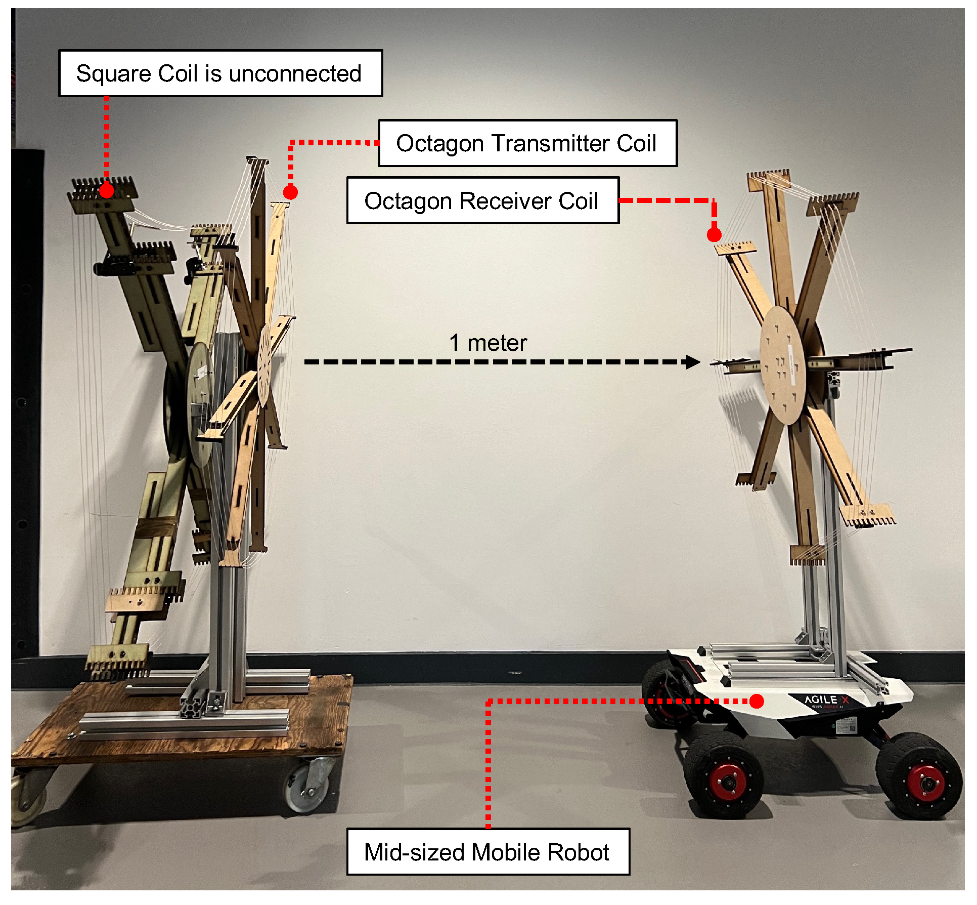
Figure 2.
(a) Octagon coils, (b) irregular shape coils.
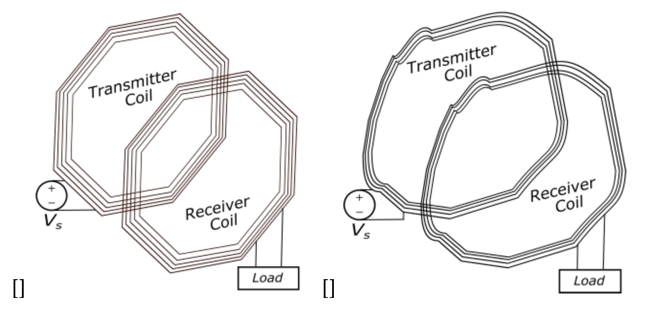
Figure 3.
Conceptual designs for retractable coil frames.
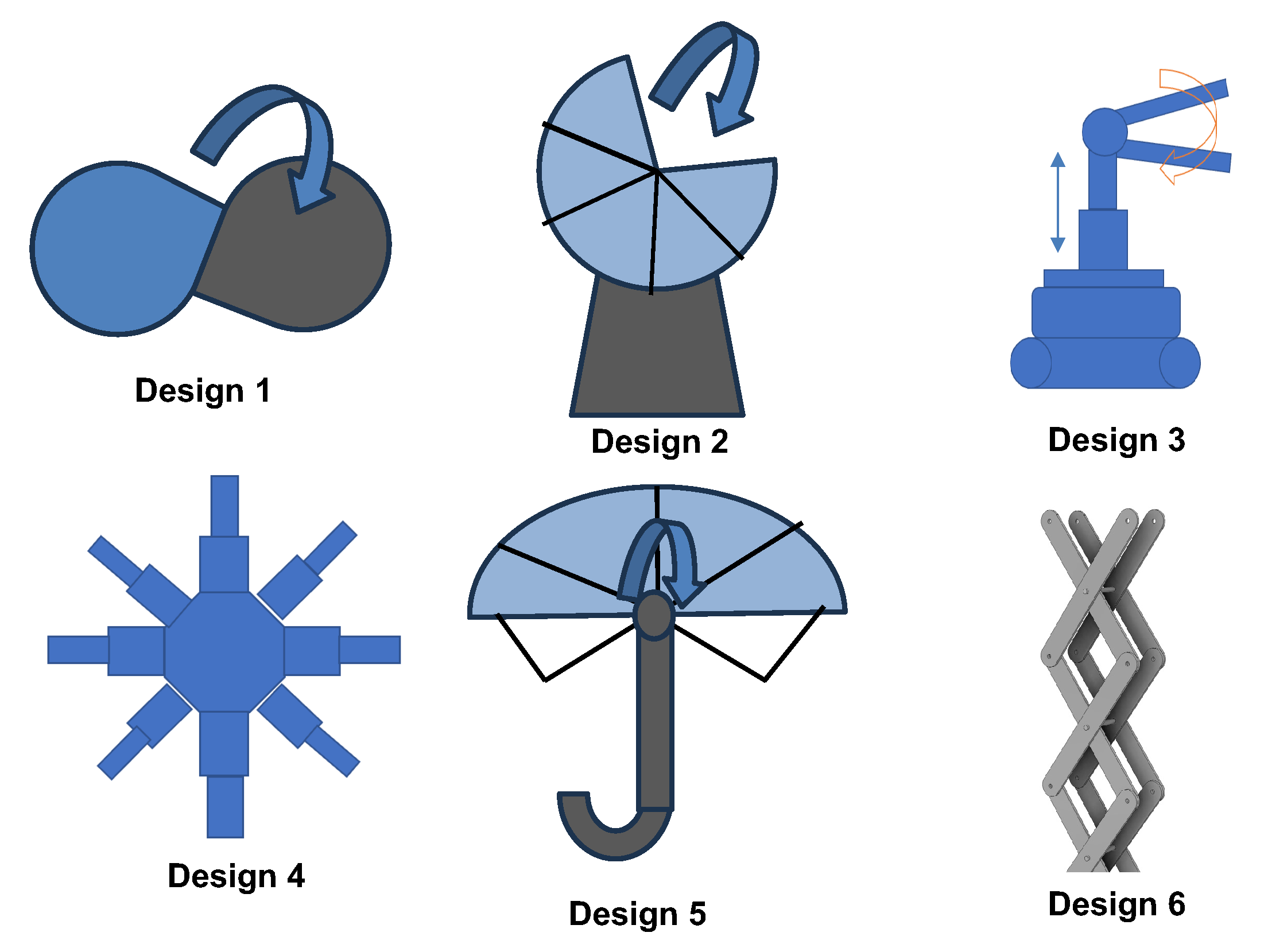
Figure 4.
Coil group by shape: (a) Group 1: triangles. (b) Group 2: four-sides. (c) Group 3: other polygons.
Figure 4.
Coil group by shape: (a) Group 1: triangles. (b) Group 2: four-sides. (c) Group 3: other polygons.
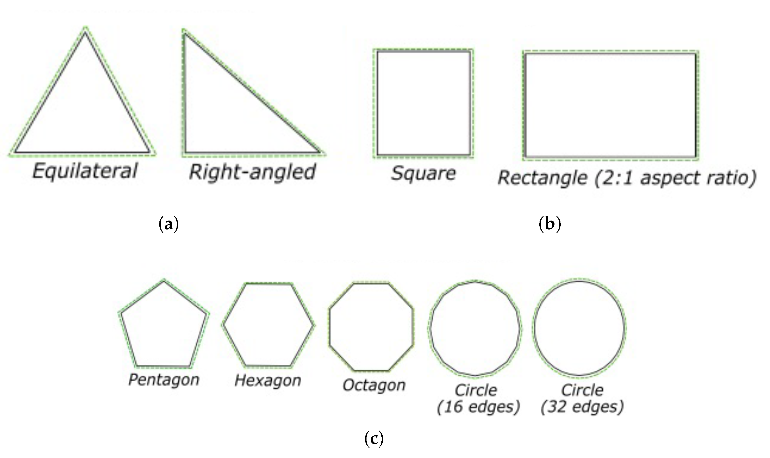
Figure 5.
(a) Lateral misalignment along x-axis between Tx and Rx coils (b) Angular misalignment around z-axis (Rx coils is rotated around z-axis).
Figure 5.
(a) Lateral misalignment along x-axis between Tx and Rx coils (b) Angular misalignment around z-axis (Rx coils is rotated around z-axis).
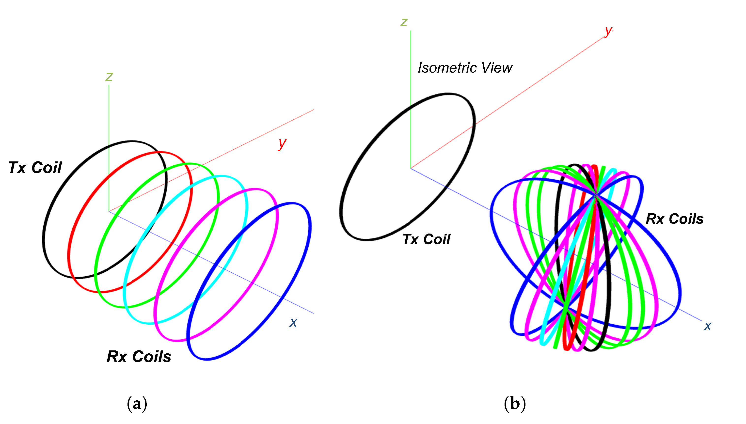
Figure 6.
Linear misalignment vs. k along linear translation of: (a) x-axis. (b) y-axis. (c) z-xis. Angular misalignment vs. k rotation about: (a) x-axis. (b) y-axis. (c) z-axis.
Figure 6.
Linear misalignment vs. k along linear translation of: (a) x-axis. (b) y-axis. (c) z-xis. Angular misalignment vs. k rotation about: (a) x-axis. (b) y-axis. (c) z-axis.
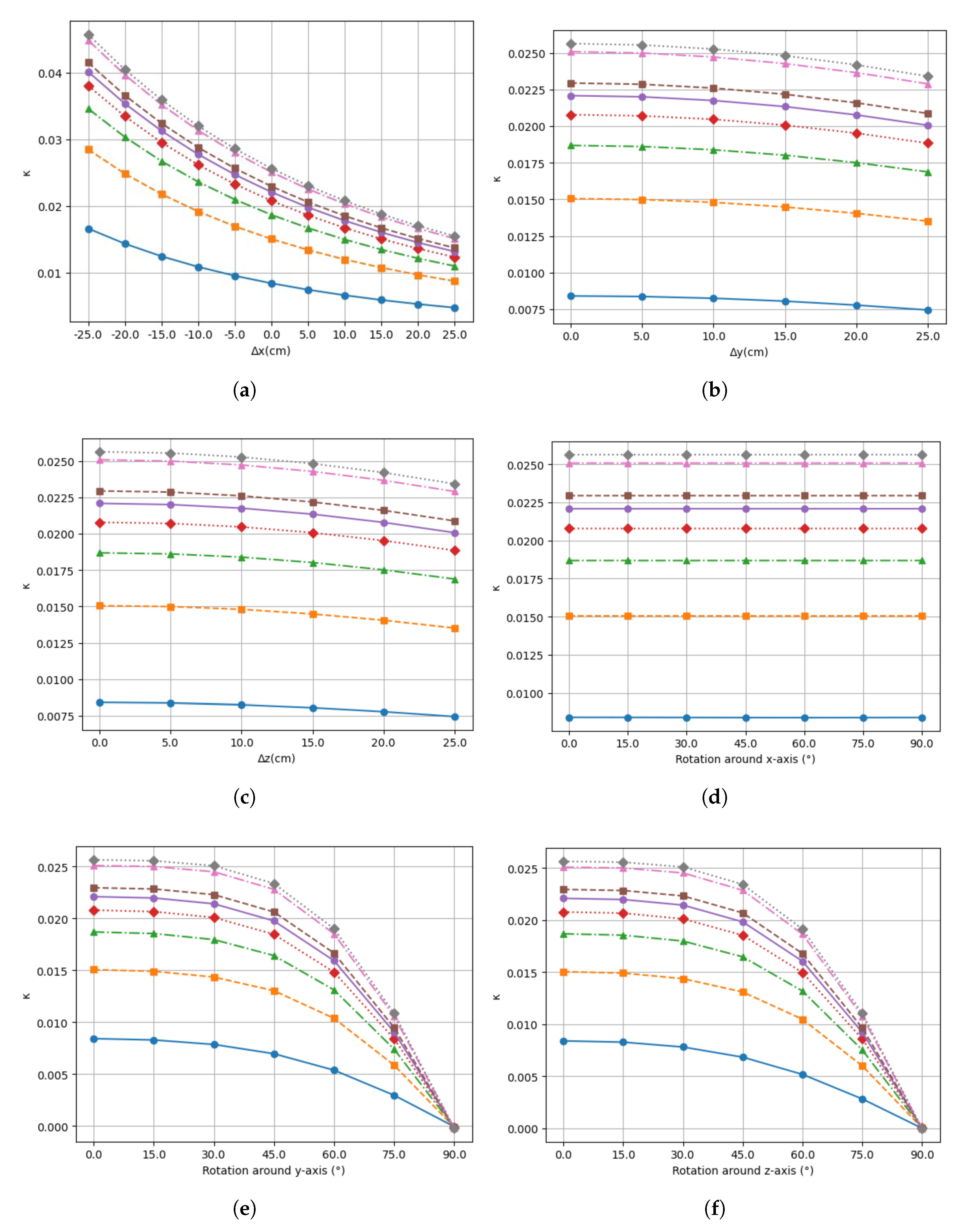
Figure 7.
FOM with component metric and corresponding weights for different geometrical shapes WPT coils.
Figure 7.
FOM with component metric and corresponding weights for different geometrical shapes WPT coils.
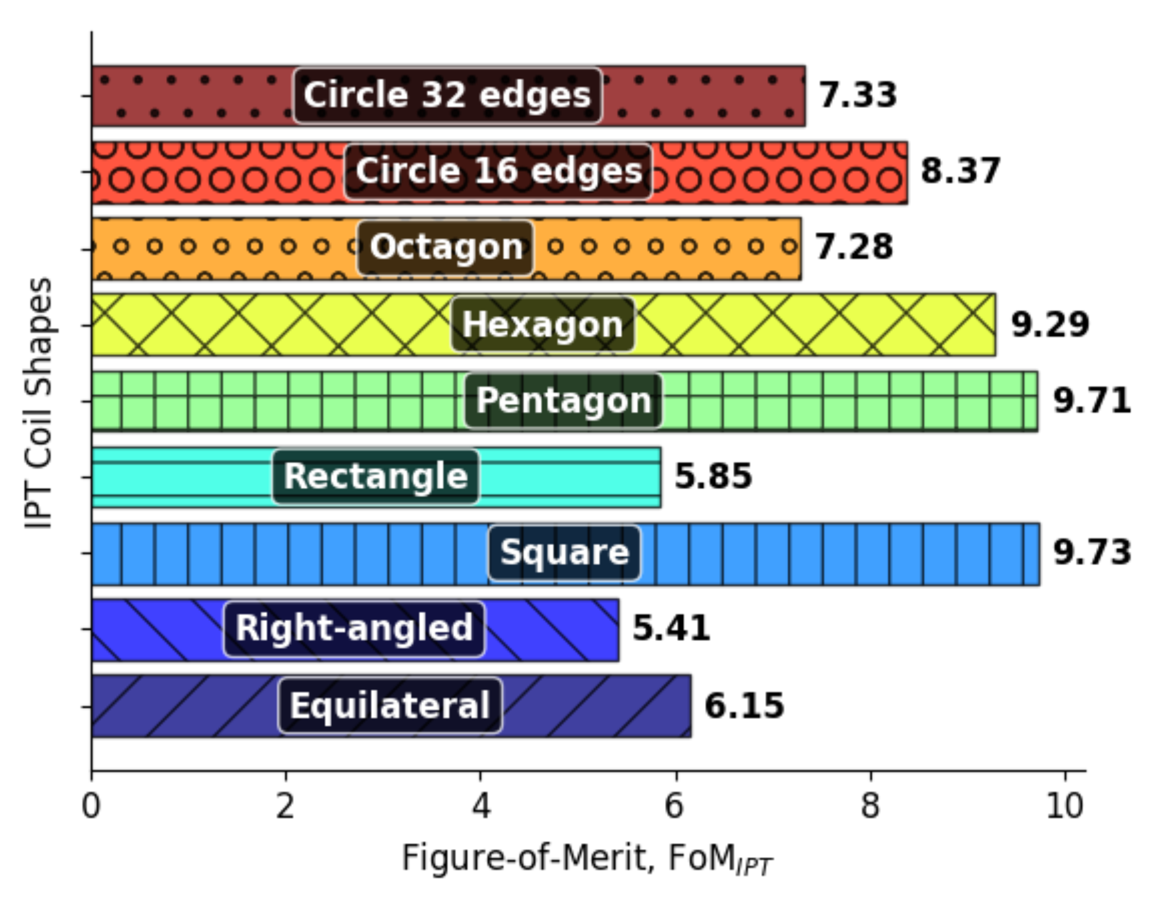
Figure 8.
(a) Fully expanded. (b) Retractable coil with pull string retraction.
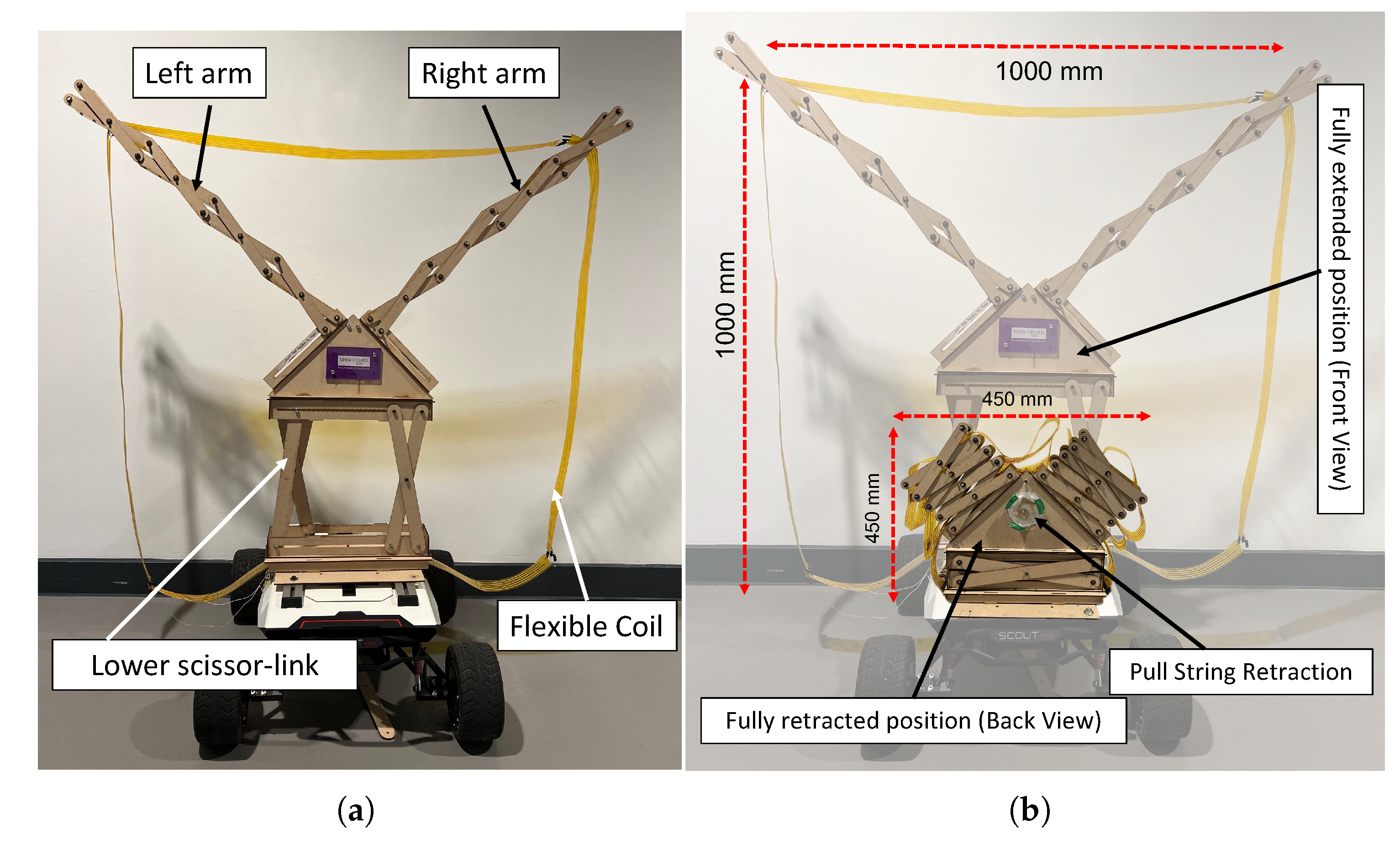
Figure 9.
Experimental setup using half-bridge driver board connected to the SC-WPT system with retractable Rx coil.
Figure 9.
Experimental setup using half-bridge driver board connected to the SC-WPT system with retractable Rx coil.
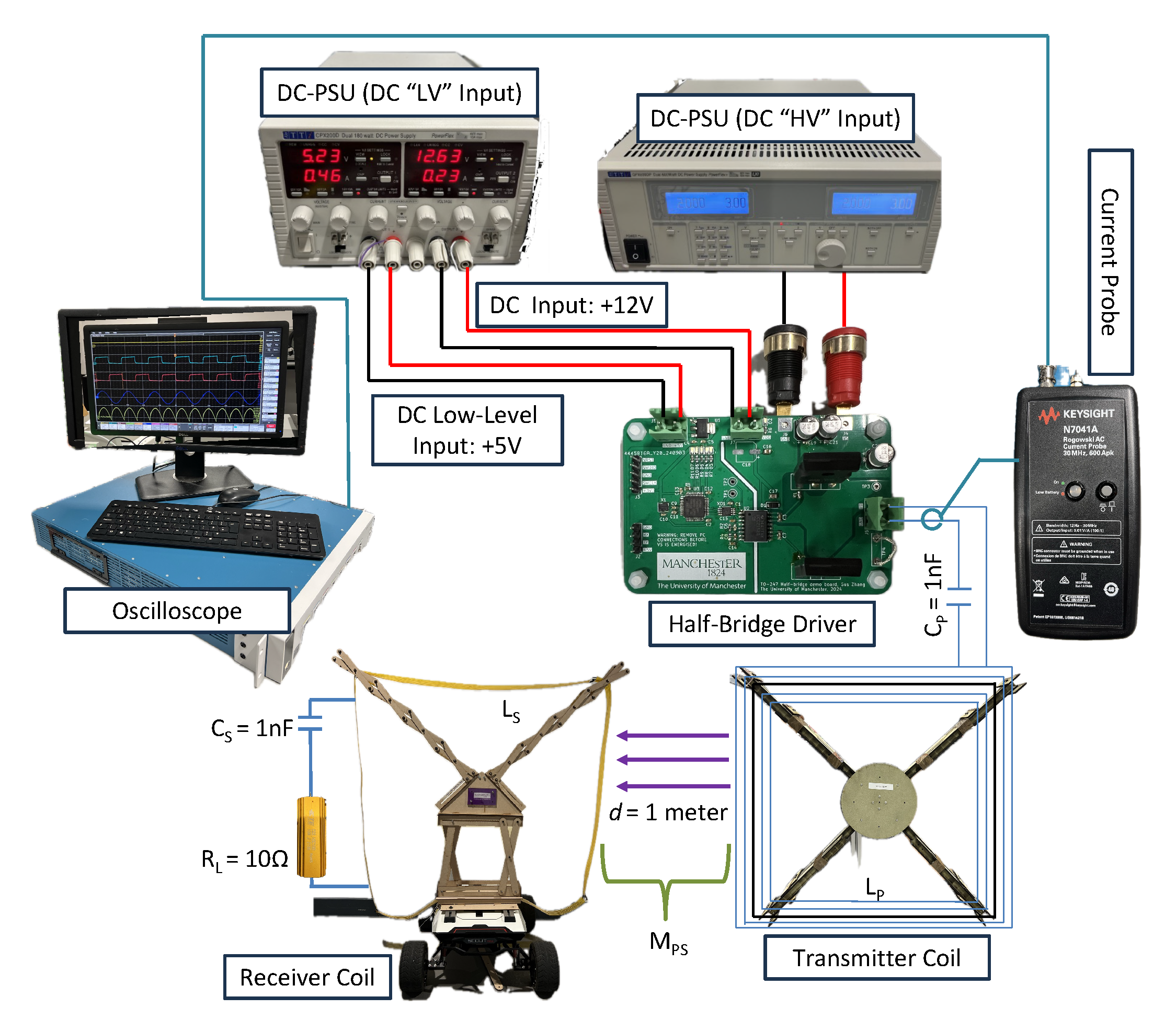
Figure 10.
Experimental setup.
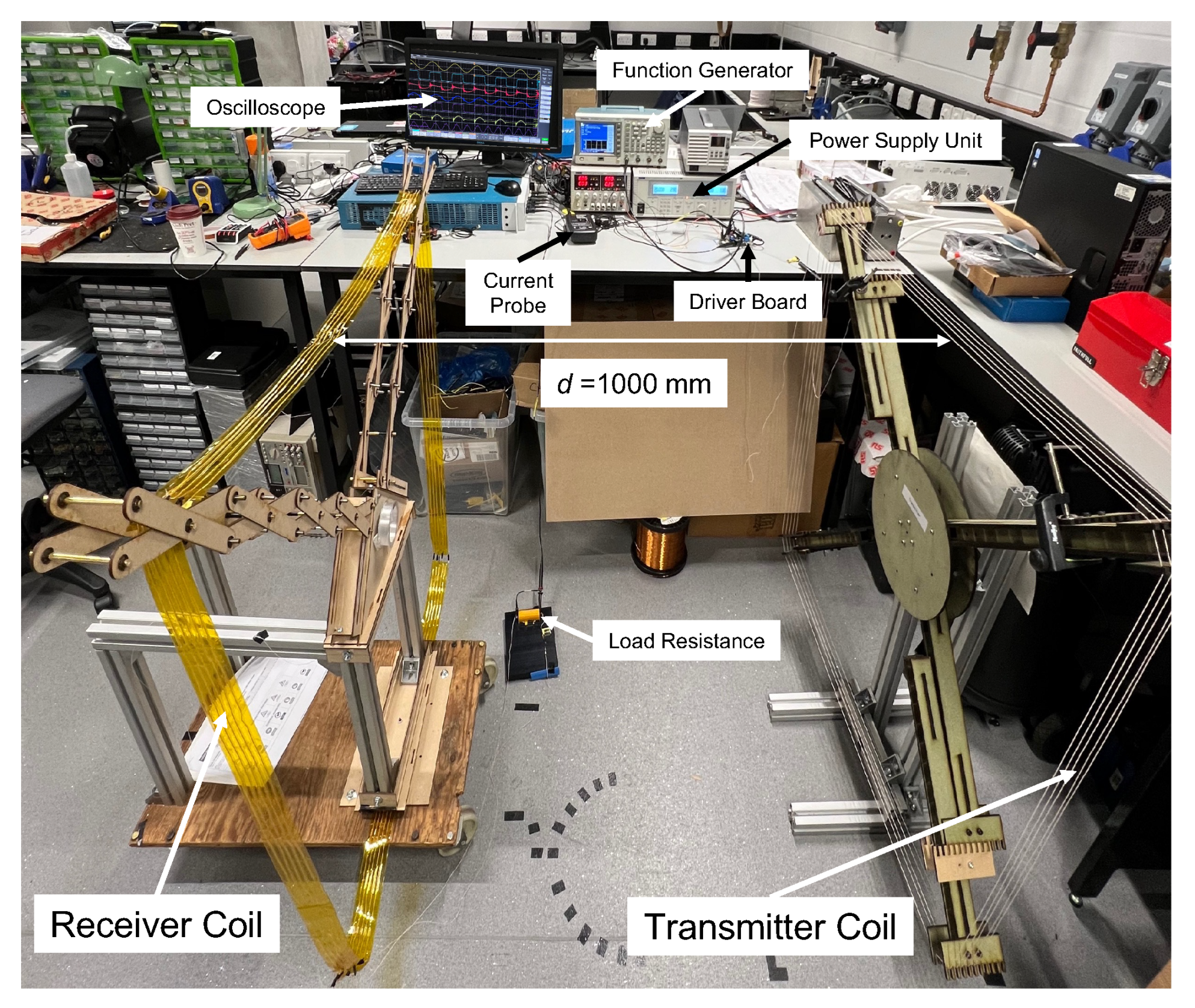
Figure 11.
(a) of lateral misalignment along x-axis. (b) of angular misalignment around z-axis.
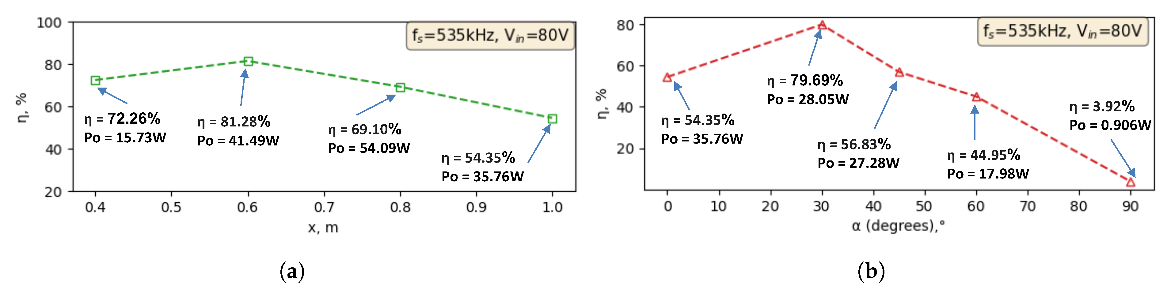
Figure 12.
(a) from lateral misalignment along x-axis. (b) from lateral misalignment along x-axis.
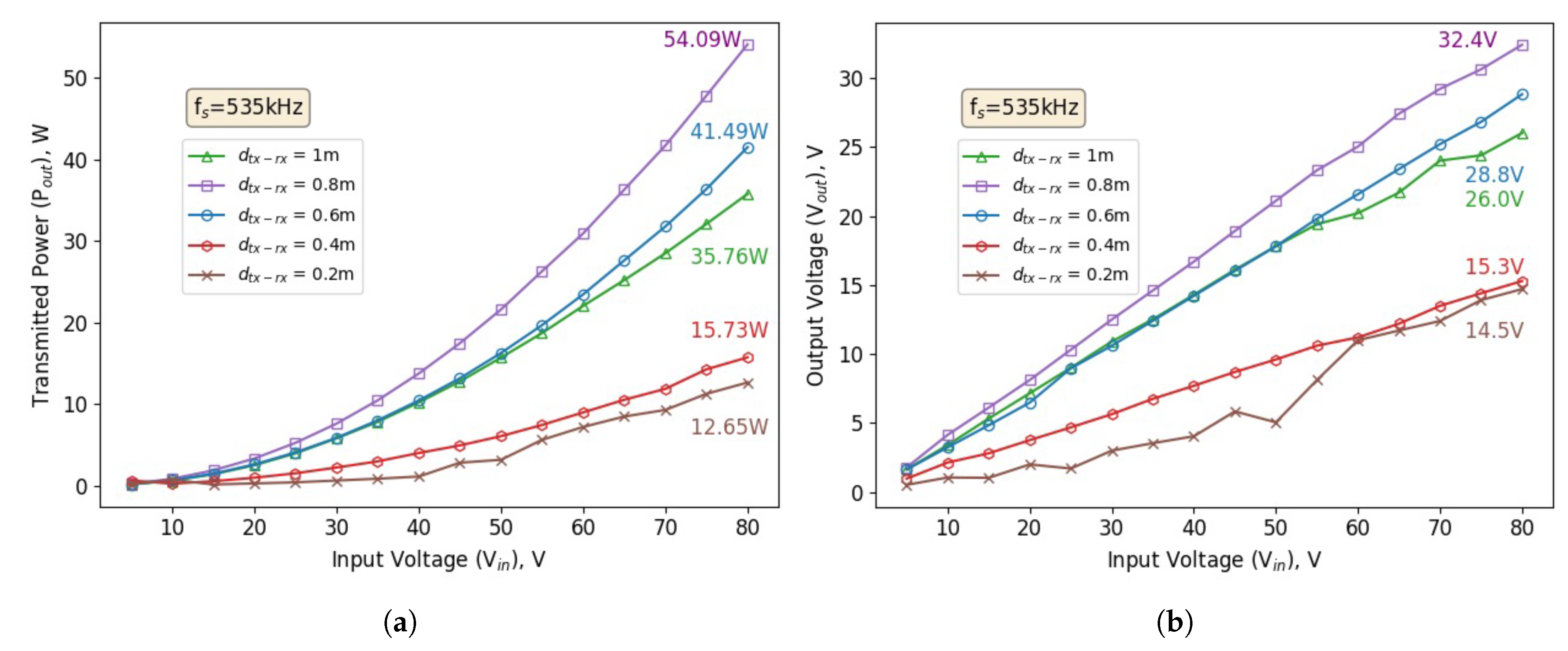
Figure 13.
Waveforms from the experimental verification.
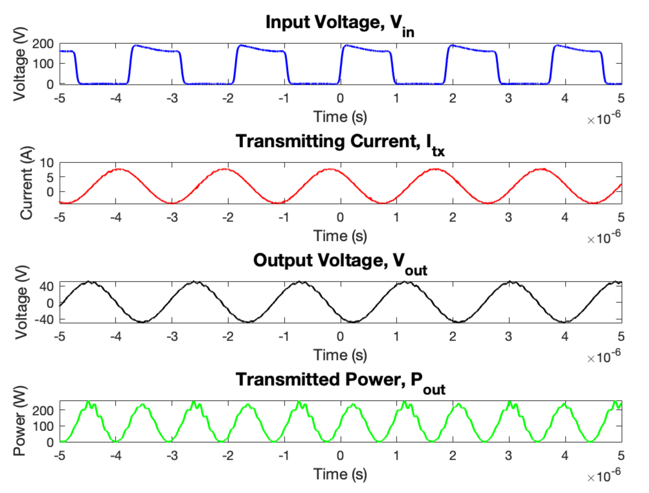
Figure 14.
Achieving transmitting power of 100 W using SC-WPT system over 1 meter of distance.
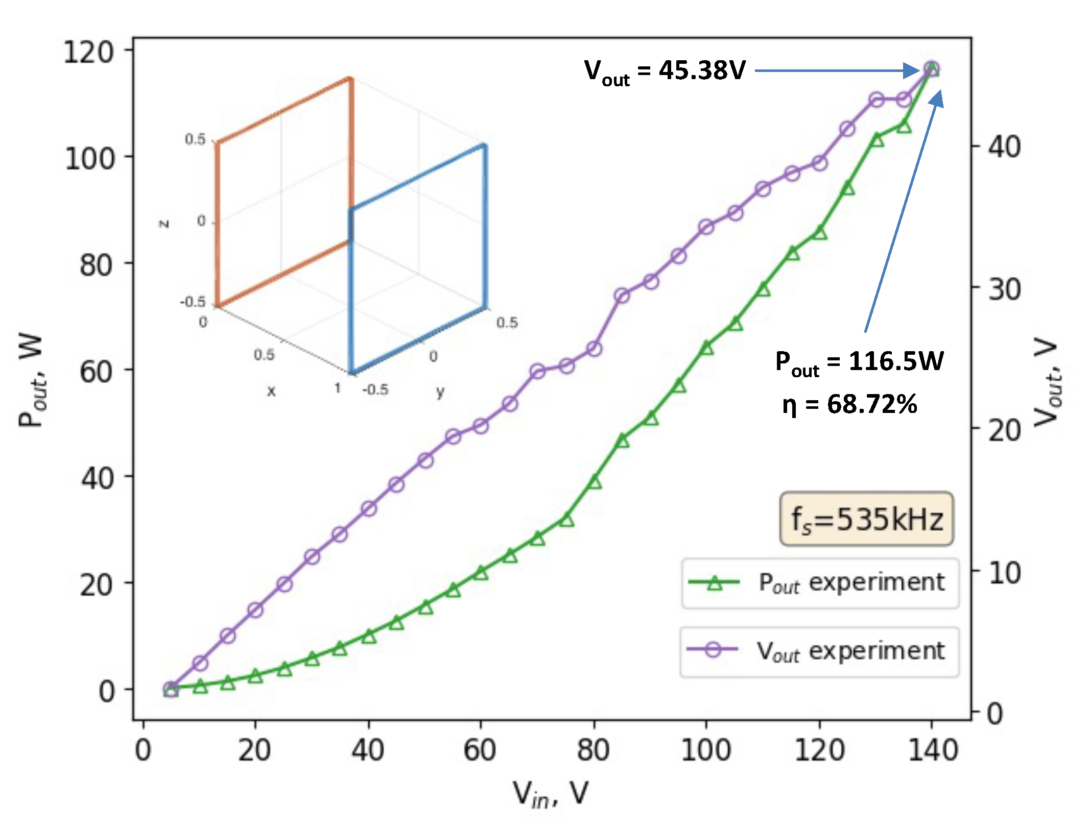
Figure 15.
(a) of lateral misalignment along the x-axis. (b) of angular misalignment around the z-axis ( = 1m).
Figure 15.
(a) of lateral misalignment along the x-axis. (b) of angular misalignment around the z-axis ( = 1m).
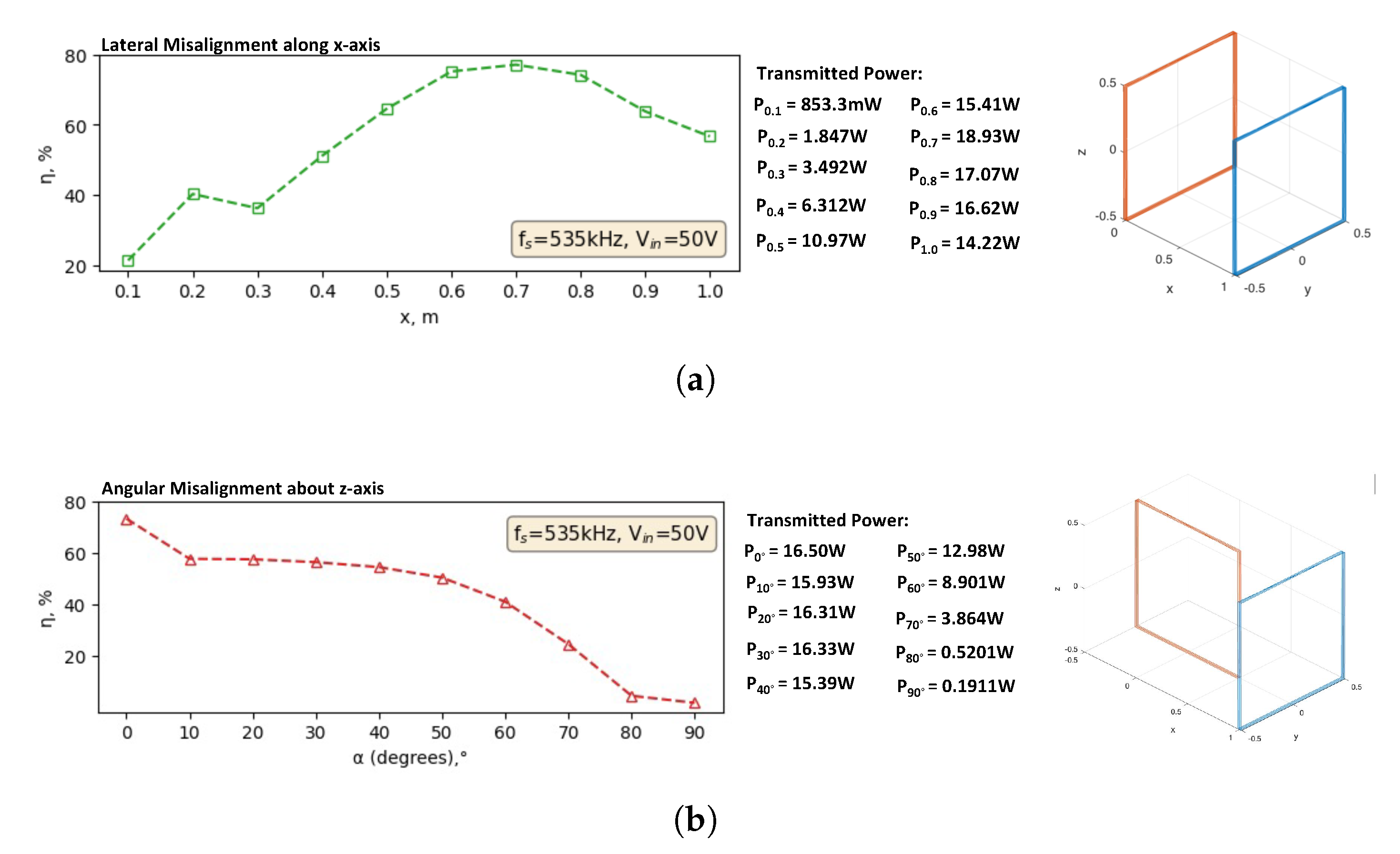

Table 1.
Parameters on the robot’s power and battery requirements.
| Mobile Platform | P (W) | T (h) | (Wh) | t (h) | W (kg) |
|---|---|---|---|---|---|
| Husky [9] | 160 | 3–8 | 480 | 4 | 75 |
| ANYmal [2] | 300 | 2–4 | 900 | 4 | 10 |
| Lily Hexapod [14] | 360 | 1–2 | 98 | 1 | 30 |
| Phantom Pro 4 [15] | 178 | 0.5 | 89 | 0.56 | 0.5 |
| Matrice 300 [16] | 198 | 1 | 36 | 2 | 3.6 |
| Hydrus-300 [5] | 99 | 1.5 | 99 | 3.5 | 6.4 |
| BlueROV [17] | 133 | 0.5–2 | 266 | 2 | 5 |
Table 2.
Conceptual designs matrix.
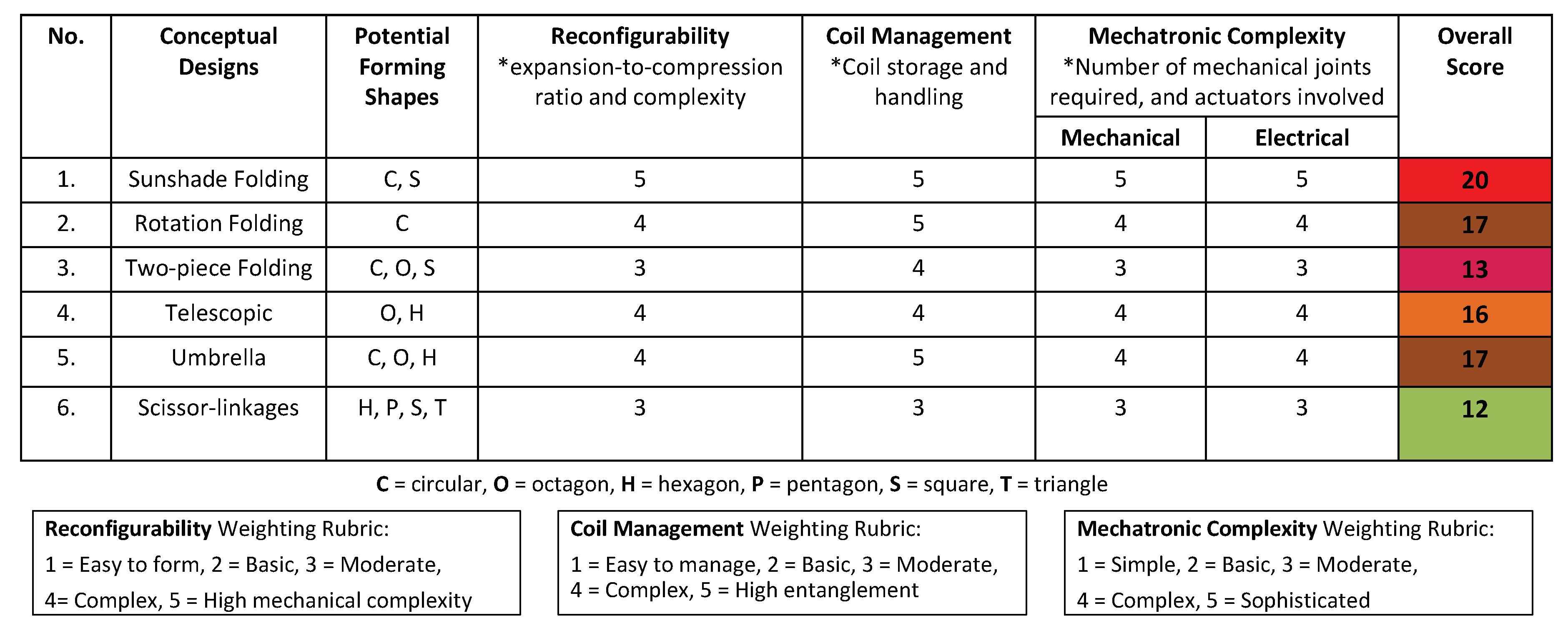 |
Table 3.
Simulated results for geometrical coil shapes with fixed input power of 200 W and five coil turns.
Table 3.
Simulated results for geometrical coil shapes with fixed input power of 200 W and five coil turns.
| Coil Shape | () | M (H) | k | (W) | (%) |
|---|---|---|---|---|---|
| Group 1: Triangle (N = 3) | |||||
| Equilateral | 0.3510 | 0.805 | 0.0142 | 146.65 | 73.32 |
| Right-angled | 0.3703 | 0.781 | 0.0133 | 140.84 | 70.42 |
| Group 2: 4-sided (N = 4) | |||||
| Square | 0.4112 | 2.37 | 0.0318 | 181.33 | 90.67 |
| Rectangle (2:1 ratio) | 0.3254 | 0.796 | 0.0145 | 150.01 | 75.01 |
| Group 3: Other polygon (N = 5, 6, 8, 16, 32) | |||||
| Pentagon | 0.3799 | 2.09 | 0.0299 | 181.23 | 90.61 |
| Hexagon | 0.3653 | 1.96 | 0.0290 | 180.87 | 90.44 |
| Octagon | 0.3481 | 1.85 | 0.0281 | 180.73 | 90.37 |
| Circle (16 edges) | 0.3387 | 1.77 | 0.0272 | 180.33 | 90.17 |
| Circle (32 edges) | 0.3363 | 1.76 | 0.0270 | 180.31 | 90.16 |
Disclaimer/Publisher’s Note: The statements, opinions and data contained in all publications are solely those of the individual author(s) and contributor(s) and not of MDPI and/or the editor(s). MDPI and/or the editor(s) disclaim responsibility for any injury to people or property resulting from any ideas, methods, instructions or products referred to in the content. |
© 2025 by the authors. Licensee MDPI, Basel, Switzerland. This article is an open access article distributed under the terms and conditions of the Creative Commons Attribution (CC BY) license (http://creativecommons.org/licenses/by/4.0/).
Copyright: This open access article is published under a Creative Commons CC BY 4.0 license, which permit the free download, distribution, and reuse, provided that the author and preprint are cited in any reuse.


