
Submitted:
08 May 2025
Posted:
09 May 2025
You are already at the latest version
Abstract
Conventional model-free control (MFC) is widely used in motor drives for its simplicity and model independence, yet suffers from inaccurate disturbance estimation and parameter mismatches. This paper proposes an adaptive enhanced model-free speed control (AEMFSC) scheme for permanent magnet synchronous motors (PMSMs) that integrates a nonlinear disturbance observer (NDO) with PD control to improve disturbance rejection and tracking performance. The method eliminates steady-state errors, reduces speed overshoot, and achieves faster settling compared to conventional approaches. An online parameter identification technique adapts the input gain α to varying loads, while an algebraic framework optimizes initial α selection. Experimental results confirm enhanced robustness against load and parameter variations.
Keywords:
model-free speed control
; ultra-local model
; adaptive gain tuning
; permanent magnet synchronous machine
1. Introduction
Permanent magnet synchronous motor (PMSM) offer high power density, efficiency, and low maintenance, making them widely used in applications such as radar, photoelectric detection systems [1]. In PMSM speed control system, a double closed-loop structure is commonly used, consisting of an outer speed loop and an inner current loop. The speed controller plays a key role in ensuring precise speed tracking and effective suppression of load disturbances.
Proportional-integral (PI) control is widely used in PMSM drive systems due to its simplicity, clarity, and effectiveness [2,3]. However, practical challenges such as motor parameter uncertainties, and unknown load disturbances limit its speed control performance. To address these issues, advanced control methods, including internal model control [4], sliding mode control [5], adaptive control [6], fuzzy control [7], and model predictive control (MPC) [8], have been applied to speed loops.
A key challenge in sliding mode control is the buffeting phenomenon caused by high-frequency switching. High-order sliding mode control techniques have been developed to mitigate this issue [9]. Adaptive sliding modes enhance the robustness of the system in the face of uncertainty and parameter variations, but increase the complexity and computational effort of the system [10]. Adaptive control is more complex than traditional methods, and although adaptive controllers can gradually adapt to changes in parameters, they often struggle to respond quickly to sudden changes [11,12].
Disturbance/uncertainty estimation and attenuation (DUEA) [13] control enhances system robustness by estimating and compensating for disturbances and uncertainties in real time. Since the 1960s, various DUEA techniques based on different estimation methods have been developed. Among these, disturbance observer-based control (DOBC) and extended state observer-based control (ESOC, known as ADRC) are the most widely studied and applied in AC motor drives. As a key component of DOBC, DOB was first proposed by Ohnishi [14] in the 1980s to enhance the disturbance rejection capability and robustness of DC motor drives. In DOBC, the disturbances/uncertainties are estimated by the observer and compensated by the estimated disturbances/ uncertainties [15,16]. ADRC was introduced by Han in the 1990s as a practical control method to replace classical PID controllers [17]. To simplify ADRC design, a linear extended state observer (LESO) is proposed [18]. LESO is often combined with other control methods, and the robustness of PMSM system can be improved by feedforward compensation of lumped disturbance estimated by LESO [19,20].
Recently, ultra-local model (ULM)-based model-free control (MFC), proposed by Fliess and Join [21], has gained significant attention in areas such as PMSM, autonomous vehicle trajectory, and energy system management. MFC is a control strategy that does not require a precise mathematical model of the system, but uses the input and output data of the system to adjust in real time. Compared to ADRC, MFC has fewer control parameters and does not need knowledge of the system’s order. In [22], a model-free control strategy based on ultra-local models is proposed for current control in PMSM and later extended to speed control [23]. However, both methods face issues with complex lumped disturbance estimation and long computation times. To address this, a new observer was designed based on the model-free current control strategy for PMSM, which significantly reduces design parameters and computational complexity [24,25,26]. MFC has some limitations, including its reliance on data quality. Since MFC depends on real-time data, it is sensitive to measurement noise and sensor accuracy. Inaccurate or noisy data can reduce performance and potentially lead to system instability or loss of control accuracy.
The control gain in the ULM serves as a critical parameter determining closed-loop system performance. In ULM-based model-free control, appears in the denominator of the control law. Too small an value may induce tracking error oscillations and control input chattering, while an excessively large can degrade control precision. Consequently, developing effective gain tuning strategies for ULM-based model-free control remains crucial [27]. To enhance ULM control performance, several variable-gain model-free approaches have been developed [28,29]. For instance, an online method was proposed to estimate the control gain using previous-step command signals [28]. Alternatively, in [29], the differential Riccati equation used for online gain adaptation was introduced. While these adaptive techniques have improved the overall performance of model-free control, the systematic tuning of gains for optimal performance requires further investigation.
In this study, the Nonlinear Disturbance Observer (NDO) and PD control law were integrated into a generalized model-free feedback controller to enhance the speed regulation performance of PMSMs. An -adaptive method based on gradient descent was developed to achieve optimal tracking performance, while a parameter estimation approach was designed to optimize the selection of ’s initial value. These methodologies collectively enabled the proposed controller to achieve superior performance through accurate lumped disturbance estimation, input gain adaptation, and rapid response times.The main contributions of this work are summarized as follows:
- Compared to conventional lumped disturbance estimation methods, the incorporation of NDO eliminated steady-state errors caused by load torque variations. The integration of PD control law into the generalized model-free controller effectively reduced speed overshoot, while the dead-zone method mitigated control signal oscillations induced by sensor noise.
- The proposed online adaptive estimation law ensured rapid convergence to the true value, significantly improving speed tracking accuracy.
- The algebraic framework-based linear parameter identification method enabled high-precision estimation of the true value, eliminating arbitrariness in initial value selection and enhancing transient performance during startup phases.
The remainder of this paper is structured as follows: Section 2 presents the PMSM dynamic model and conventional model-free speed control strategies. Section 3 details the novel enhanced model-free speed control (EMFSC) framework and the proposed input gain identification methodology. Comparative analysis of simulation and experimental results is provided in Section 4. Finally, the conclusions are presented in Section 5.
2. Conventional Model-Free Speed Control Based on Ultra-local Model
2.1. Mathematical Model of SMPMSM Direct Drive System
Considering the parametric uncertainties and unknown external disturbance, the electromechanical equation of PMSM complex direct drive system is given as
where is rotor mechanical rotational speed; and express the nominal values of rotational inertia and the friction coefficient, respectively; stands for the electromagnetic torque; denotes the load torque; is the constant disturbance; express disturbance induced by the parametric uncertainties and other unknown disturbance; is the pole pair number; express the nominal values of permanent-magnet flux linkage; and represent d- and q-axes currents, respectively; and are the stator inductances of the d- and q-axes, respectively.
For the surface-mounted PMSM, the d- and q-axes inductances are equal (). Then, the electromagnetic torque can be represented as follows:
From Equation (1), the motion dynamics can be expressed as
2.2. Principle of Conventional ULM-Based Model-Free Control
The first-order ultra-local model of a single-input single-out system is expressed as [21]
where y and u are output and control variables, respectively; represents a nonphysical scaling factor selected by the designer; and F represents the known and unknown part of the system. Defining tracking error , the error dynamic can be gotten as
where is the desired output. To converge the tracking error e, a generalized model-free feedback controller is proposed as
where denotes the error convergence law.
In [23], the principle of model-free control based on ultra-local model with algebraic parameter identification is applied to the speed control of a SMPMSM drive and the corresponding controller is called "conventional MFSC" (MFSC-API). The reference of torque is calculated as
where donates the estimated value of the lumped disturbance , is the desired speed, the symbol "(k)" represents value of above variable at the (k)th control period, represents the parameter of the controller. For the mechatronic system described in (3), in the presence of a mismatch between the controller’s initial parameters and the true machine parameters, the lumped disturbance can be mathematically characterized as
Within a sufficiently "small" time interval, is treated as a constant parameter and estimated through an algebraic parameter identification technique (API) [30], expressed as:
where is the data window and ; is the data window length; is a sliding data window.
According to the ultra-local model, should be designed to keep and in the same order of magnitude. The control performance of the system may be adversely affected by improper selection of the parameter. Given this, the tuning of the input gain has a significant impact on the stability and tracking accuracy of control system.
3. Principle of the Proposed AEMFSC-NDO
In this section, an adaptive enhanced model-free speed control framework based on the ultra-local model is developed. First, a nonlinear disturbance observer (NDO)-enhanced model-free controller (EMFSC-NDO) is developed by integrating a nonlinear disturbance observer with proportional-derivative (PD) control architecture. Subsequently, an adaptive law for the control input gain is derived via gradient descent method, resulting in an adaptive EMFSC-NDO method (AEMFSC-NDO). Finally, an initial value determination method for the control input gain is derived based on algebraic differentiation techniques.
3.1. Enhanced Model-Free Speed Control via Nonlinear Disturbance Observer
In this article, according to (3), considering the SMPMSM q-axis current as output variable, the ideal ultra-local mathematical model of SMPMSM can be expressed as
where the output , the input , the theoretical control gain , and the lumped disturbance .
The practical difficulty in obtaining accurate machine parameters leads to a parametric mismatch between the designed ultra-local model and the true system dynamics. Therefore, the practically realized ultra-local model takes the following form:
where the lumped disturbance . With model (11) as the basis, the model-free feedback control scheme (6) is subsequently deployed. However, the existence of results in control law (6) not being implemented. To achieve precise and rapid real-time estimation of , the nonlinear disturbance observer (NDO) is designed as follows [31]:
where Z is an auxiliary variable, L is the positive gain of the nonlinear disturbance observer, is the estimated value of the lumped disturbance.
Take the derivative of the observer error , and using (11), then yields
Considering that the total disturbance and are bounded, which is . According to the principle of Lyapunov function stability, the nonlinear disturbance observer system is progressively stable.
To enhance the transient tracking performance of the speed control system, a PD control law is employed to ensure the convergence of the tracking error. Therefore, the enhanced model-free controller is proposed as
where are the control parameters.
To prevent amplification of high-frequency noise in speed tracking error differentiation, which may cause control signal chattering and potential system instability, a dead-zone method is implemented in the controller. This approach suspends error derivative calculation when the error magnitude falls below a predefined threshold. Specifically, the dead-zone implementation follows as
where is the error threshold.
Taking the control law (14) into the tracking error dynamics (5) based on (10), one has the following error equation:
where , , the residual disturbance . Then, rewrite above equation as follow:
where
The Lyapunov function is defined as , where denotes a positive real number. Taking the derivative of V, it yields
where represents the upper bound of . Obviously, when , can be guaranteed. Furthermore, one gets
Thus, the closed-loop system is asymptotic stability and the tracking error is uniformly ultimately bounded.
3.2. Adaptive Enhanced Model-Free Speed Controller Design
The gain critically determines both the closed-loop stability and speed regulation quality in PMSM drives. This work proposes a gradient descent-based online auto-tuning scheme to optimize this essential parameter.
The above (11) can be discretized as follows:
where is the sampling time. since the change period of the lumped disturbance F is much larger than the period of the sampling time , it can be considered that the lumped disturbance is unchanged in the adjacent sampling period, namely
On this basis, we have
with
Then, the output error can be expressed as
Consider the following index function:
Then, the gradient of the index function with respect to is given by:
The presence of measurement noise in the error signal can corrupt the gradient estimation, causing the parameter to oscillate randomly around or deviate cumulatively from its true value. To enhance the adaptation law, a dead-zone technique is introduced to suppress noise effects by disabling updates during small-error conditions. The implementation details are as follows:
where is the error threshold. Therefore, the update law for is given as follows
where is the learning rate.
To prevent instability in parameter adaptation caused by excessively large or small control inputs , a nonlinear modulation scheme is applied to the learning rate. The learning rate is dynamically adjusted based on the input variation , as specified below
By incorporating this nonlinear modulation scheme into the standard gradient update law, the final adaptation rule can be gotten as
where is the adaptive coefficient, is the initial value of .
Combining nonlinear disturbance observer (12), enhanced model-free speed control law (14), and adaptive gain law (30) based on gradient descent method, the final adaptive enhanced model-free speed controller (AEMFSC) is designed as
The block diagram of the proposed PMSM speed control strategy is shown in Figure 1.
3.3. Initial Value Estimation Method for the Input Gain
In practical motor applications, two major challenges exist: (1) inaccuracies or missing specifications of flux linkage parameters and torque coefficients on nameplates, and (2) considerable difficulties in accurately estimating moment of inertia under complex loading conditions, resulting in significant deviations between calculated and actual values.
For constant-load motor systems, employing a fixed value effectively reduces computational overhead in embedded systems. For variable-load systems, appropriate initial values substantially enhance transient tracking performance during the startup phase. This subsection consequently presents an algebraic framework-based linear identification method for high-precision identification.
The electromechanical equation (3) of SMPMSM drive system can be expressed as
where is the rotor mechanical angle, , , , and . The constant parameters are unknown, and the is considered to be a constant load perturbation [32]. Then (32) in S-domain is given as
Introduce a first order low pass filter, given by
where the known constant parameters is strictly positive. Thus
Multiplying both sides of (35) by s yields:
Derive both sides three times with respect to s, in order to eliminate the unknown parameter , and the initial conditions , :
Then multiply both sides by for avoiding derivations with respect to time:
The remaining negative powers of s correspond to iterated time integrals. The corresponding formulae in the time domain are easily deduced thanks to the correspondence between , and the multiplication by in the time domain. Equation (38) in time domain can be obtained as
with
We have denoted by the quantity . Moreover, .
Integrating the expression (40) one time, leads to the following system of linear equations for the estimates , of the unknown parameters:
with
4. Simulation and Experimet Results
This section conducts a rigorous comparative evaluation of the proposed EMFSC-NDO (14) and AEMFSC-NDO (31), comparing them with two control methods: conventional MFSC-API [23] and MFSC-NDO (7). The assessment examines transient response, steady-state accuracy, and disturbance rejection capabilities under identical operating conditions.
Both simulation and experimental studies are performed on a SMPMSM drive system, utilizing a two-level voltage source inverter with SVPWM at 10 kHz switching frequency. The dead-time is set as 0.5s. Decoupled PI regulators are adopted in the current loop, and these controllers are employed in the speed loop. The speed loop frequency is 2 kHz. Table 1 lists the specification of the SMPMSM used in the digital simulation and experimental tests.
All control parameters are optimized through systematic trial-and-error procedures to ensure optimal tracking performance and disturbance rejection capabilities. Notably, the simulation model incorporates realistic encoder quantization effects by superimposing discrete position measurement noise.
4.1. Simulation Results
Numerical simulations of the PMSM speed regulation system are conducted using MATLAB/Simulink, with the control algorithm executed in discrete-time domain at 2 kHz sampling rate.
The parameters of MFSC-API, MFSC-NDO, EMFSC-NDO, and AEMFSC-NDO controllers are chosen as follows: = 160, = 10 for MFSC-API controller, = 400, L = 50 for MFSC-NDO controller, = 400, = 1, L = 50, = 0.3 rad/s for EMFSC-NDO controller, and = 400, = 1, L = 50, = 0.3 rad/s, = 20 for AEMFSC-NDO controller. The reference speed is 90 rpm, and the inertia of the load is chosen as = 0.00134 kg·m2. Therefore, the theoretical ture value of input gain .
Figure 2 shows the startup responses of the MFSC-API, MFSC-NDO, EMFSC-NDO, and AEMFSC-NDO controllers at the reference speed of 90 rpm. The load torque is initially set to zero, so the PMSM can be assumed to be load-free. Figure 2 clearly demonstrates that both the EMFSC-NDO and AEMFSC-NDO controllers exhibit superior dynamic performance, achieving minimal overshoot and the fastest settling time among all compared methods. However, when the selected input gain and the theoretical true input gain mismatched, the performance of PMSM system will deteriorate.
Figure 3 presents a comparative analysis of disturbance rejection capabilities among the four control schemes. The results demonstrate that the proposed AEMFSC-NDO controller exhibits superior load disturbance rejection, with merely 18.4% speed drop during sudden load torque application (4.0 N·m step change at t=0.25s), compared to 25.7% for the MFSC-NDO method. Furthermore, parameter mismatch analysis reveals that input gain variations can degrade the system’s disturbance rejection performance .
To validate the effectiveness of the adaptation algorithm, three distinct initial value conditions were experimentally tested. As demonstrated in Figure 4, the results show that: (i) the estimated input gain converges to its theoretical actual value within several square-wave cycles, and (ii) the automatic adjustment of parameter significantly reduces transient tracking errors.
The preceding analysis reveals that while the proposed AEMFSC-NDO demonstrates exceptional robustness and rapid tracking performance, inappropriate initial values of can adversely affect transient tracking during startup and potentially destabilize the system. To obtain accurate values, the algebraic framework-based linear identification method is employed for precise input gain estimation. The estimation procedure, validated under three distinct load inertia conditions (), operates as follows: (a) Initialize with an overestimated value (e.g., =1000); (b) Execute maximum-speed square-wave rotation; (c) Compute via (41) using measured position and q-axis current. Figure 5 confirms high estimation accuracy across all test cases. Notably, this computationally intensive method may require offline implementation on resource-constrained DSPs after data acquisition.
4.2. Experimental Results
To further verify the effectiveness of the proposed control scheme, some real-time experiments are carried out. Figure 6 depicts the experimental test platform, which is governed by a TMS320F28379D digital signal processor (DSP). The control circuit is composed of power supply (RU-36-10036), SPMSM (J155LWX001), two-level inverter, and measurement circuit.
A MOSFET module inverter is fed by a programmable DC power supply, set at 34V in the experiments. The rotor position sensor is a 19-bit electromagnetic encoder (EAB42-0M19S-8-B) and the current sensor is a CC6920B-10A current sensor. The nominal parameters of the motor, the sampling time and all the parameters of the current controller are the same as in the simulation.
To mitigate sensor noise amplification and prevent motor oscillations, practical controller implementations employ smaller parameter values compared to simulation environments. The parameters of MFSC-API, MFSC-NDO, EMFSC-NDO, and AEMFSC-NDO controllers are chosen as follows: = 80, = 10 for MFSC-API controller, = 300, L = 50 for MFSC-NDO controller, = 300, = 1, L = 50, = 0.3 rad/s for EMFSC-NDO controller, and = 300, = 1, L = 50, = 0.3 rad/s, = 10 for AEMFSC-NDO controller.
For systems with uncertain load inertia and motor parameters, an algebraic framework-based linear identification method can be employed to achieve precise identification of the input gain. Figure 7 displays the estimation results of parameter derived from three experimental trials under distinct load conditions. The initial angle position of the motor is different each time. The inertia of each load disk is . The estimated values exhibit remarkable consistency across all trials, aligning closely with the simulation outcomes. This agreement further validates the efficacy of the algebraic framework-based linear estimation method in accurately determining the input gain parameter . The estimated gain value can be directly employed as the fixed parameter in the EMFSC-NDO approach or serve as the initial value for in the adaptive AEMFSC-NDO scheme.
Applying the aforementioned algebraic framework-based linear identification method, the input gain is identified as =300 when the load is a magnetic powder brake. Figure 8 compares the startup responses of MFSC-API, MFSC-NDO, EMFSC-NDO, and AEMFSC-NDO controllers under no-load conditions at 60 rpm reference speed. As demonstrated in Figure 8(a) with accurate input gain, the proposed EMFSC-NDO and AEMFSC-NDO controllers exhibit superior transient performance. Although the MFSC-API controller generates lower q-axis current peaks, it has a longer settling time. These results conclusively establish the advantages of EMFSC-NDO and AEMFSC-NDO controllers in PMSM speed transient regulation.
Figure 8(b)-(c) reveal significant sensitivity to input gain variations. When , both EMFSC-NDO and AEMFSC-NDO exhibit excessive speed overshoot, while MFSC-NDO shows relative improvement. Notably, elevated gain values universally prolong the settling time across all four controllers, potentially degrading system performance during rapid speed transitions. Table 2 quantitatively compares key performance indicators: (i) speed overshoot, and (ii) settling time, further validating the proposed controllers’ robustness against parameter mismatches.
The disturbance rejection capability is evaluated during steady-state operation by applying an 8 N·m load torque disturbance. Figure 9, Figure 10, Figure 11 and Figure 12 present the experimental results under this loading condition. As revealed in Figure 9(a), while the MFSC-API controller exhibits smaller speed drops, it suffers from significant steady-state errors that degrade control performance. Comparative results in Figure 10(a), Figure 11(a) and Figure 12(a) demonstrate that the proposed EMFSC-NDO and AEMFSC-NDO schemes achieve superior disturbance rejection compared to MFSC-NDO. The comparison between MFSC-API and MFSC-NDO further reveals inherent limitations of the algebraic parameter identification approach in estimating lumped disturbances during abrupt load changes.
Experimental results with different input gain values ( and ) show substantially increased speed deviations and prolonged settling times. This confirms that excessive input gain values severely deteriorate the system’s disturbance rejection capability. In this scenario, the proposed AEMFSC-NDO control strategy consistently outperforms both MFSC-NDO and EMFSC-NDO approaches. This superiority stems from its adaptive adjustment capability during load transients, which actively enhances disturbance rejection performance. It should be noted that when the controller input satisfies the persistent excitation condition, the AEMFSC-NDO can recover its nominal anti-disturbance performance through adaptation, even with initial parameter mismatch. Quantitative performance metrics under load torque variations are systematically compared in Table 3.
Figure 13, Figure 14, Figure 15 and Figure 16 present the square-wave speed tracking performance under 4 N·m load torque, with reference speeds ranging from 30 to 90 rpm. While the conventional MFSC-API controller exhibits steady-state errors as previously analyzed, the other three controllers achieve rapid and accurate speed tracking. However, elevated input gain values are observed to degrade the tracking performance, particularly during square-wave transitions.
Quantitative evaluation using Root Mean Square Value (RMSE, entire process) and Integral Absolute Error (IAE, steady-state phase) metrics is summarized in Table 4. With matched values, the EMFSC-NDO strategy demonstrates superior tracking accuracy and steady-state performance. Under parameter mismatch conditions, the AEMFSC-NDO’s adaptive mechanism effectively suppresses speed overshoot and maintains better high-speed tracking performance, owing to its self-tuning capability.
The effectiveness of the proposed -adaptation algorithm is validated through three distinct initial conditions, with experimental results presented in Figure 17. The data demonstrate that the estimated converges to the vicinity of its true value within several square-wave cycles. It should be noted that choosing a smaller value of will reduce the oscillation amplitude of the input gain, but this comes at the cost of a longer convergence time.
5. Conclusions
This paper has developed an NDO-based EMFSC control algorithm for PMSM systems to achieve high tracking performance under external disturbances and unknown load torque. Compared with conventional MFSC-API and MFSC-NDO methods, the proposed EMFSC-NDO eliminates steady-state errors, reduces speed overshoot, and demonstrates faster settling time with enhanced disturbance rejection capability. Furthermore, two parameter identification methods have been designed to online estimate the true input gain values, effectively addressing input gain mismatch issues. The effectiveness and superiority of the proposed approach have been thoroughly validated through both simulation and experimental results. Future work will focus on improving the convergence speed and estimation accuracy of NDO for lumped disturbances, as well as developing more advanced input gain identification techniques.
Author Contributions
Formal analysis, C.H. and D.S.; investigation, D.S.; methodology, C.H. and X.C.; project administration, X.C. and G.G.; writing—original draft preparation, C.H.;writing—review and editing, X.C. and G.G. All authors have read and agreed to the published version of the manuscript.
Funding
This research was funded by the Foundation of Basic Science (Natural Science) Research Program for Higher Education Institutions in Jiangsu Province (Grant No. 24KJD460005).
Data Availability Statement
Not applicable.
Conflicts of Interest
The authors declare no conflicts of interest.
References
- Aimeng, W.; Heming, L.; Pengwei, S.; Yi, W.; Shuting, W. Dsp-Based Field Oriented Control of PMSM Using SVPWM in Radar Servo System. In Proceedings of the IEEE International Conference on Electric Machines and Drives, 2005., 2005, pp. 486–489.
- Apte, A.; Thakar, U.; Joshi, V. Disturbance Observer Based Speed Control of PMSM Using Fractional Order PI Controller. IEEE/CAA Journal of Automatica Sinica 2019, 6, 316–326.
- Sarsembayev, B.; Suleimenov, K.; Do, T.D. High Order Disturbance Observer Based PI-PI Control System With Tracking Anti-Windup Technique for Improvement of Transient Performance of PMSM. IEEE Access 2021, 9, 66323–66334.
- Li, Y.; Ping, Z.; Huang, Y.; Lu, J.G. An Internal Model Approach for Speed Tracking Control of PMSM Driven Electric Vehicle. In Proceedings of the 2020 IEEE 16th International Conference on Control & Automation (ICCA), 2020, pp. 1416–1421.
- Ding, S.; Hou, Q.; Wang, H. Disturbance-Observer-Based Second-Order Sliding Mode Controller for Speed Control of PMSM Drives. IEEE Transactions on Energy Conversion 2023, 38, 100–110.
- Choi, H.H.; Leu, V.Q.; Choi, Y.S.; Jung, J.W. Adaptive Speed Controller Design for a Permanent Magnet Synchronous Motor. IET Electric Power Applications 2011.
- Choi, H.H.; Yun, H.M.; Kim, Y. Implementation of Evolutionary Fuzzy PID Speed Controller for PM Synchronous Motor. IEEE Transactions on Industrial Informatics 2015, 11, 540–547.
- Ahmed, A.A.; Koh, B.K.; Lee, Y.I. A Comparison of Finite Control Set and Continuous Control Set Model Predictive Control Schemes for Speed Control of Induction Motors. IEEE Transactions on Industrial Informatics 2018, 14, 1334–1346.
- Wang, B.; Shao, Y.; Yu, Y.; Dong, Q.; Yun, Z.; Xu, D. High-Order Terminal Sliding-Mode Observer for Chattering Suppression and Finite-Time Convergence in Sensorless SPMSM Drives. IEEE Transactions on Power Electronics 2021, 36, 11910–11920.
- Zhang, Z.; Yang, X.; Wang, W.; Chen, K.; Cheung, N.C.; Pan, J. Enhanced Sliding Mode Control for PMSM Speed Drive Systems Using a Novel Adaptive Sliding Mode Reaching Law Based on Exponential Function. IEEE Transactions on Industrial Electronics 2024, 71, 11978–11988.
- Sastry, S.; Bodson, M. Adaptive Control: Stability, Convergence and Robustness; Courier Corporation, 2011.
- Wu, J.; Zhang, J.; Nie, B.; Liu, Y.; He, X. Adaptive Control of PMSM Servo System for Steering-by-Wire System With Disturbances Observation. IEEE Transactions on Transportation Electrification 2022, 8, 2015–2028.
- Chen, W.H.; Yang, J.; Guo, L.; Li, S. Disturbance-Observer-Based Control and Related Methods—An Overview. IEEE Transactions on Industrial Electronics 2016, 63, 1083–1095.
- Ohishi, K.; Nakao, M.; Ohnishi, K.; Miyachi, K. Microprocessor-Controlled DC Motor for Load-Insensitive Position Servo System. IEEE Transactions on Industrial Electronics 1987, IE-34, 44–49.
- Yan, Y.; Yang, J.; Sun, Z.; Li, S.; Yu, H. Non-Linear-Disturbance-Observer-Enhanced MPC for Motion Control Systems with Multiple Disturbances. IET Control Theory & Applications 2020, 14, 63–72.
- Dai, C.; Guo, T.; Yang, J.; Li, S. A Disturbance Observer-Based Current-Constrained Controller for Speed Regulation of PMSM Systems Subject to Unmatched Disturbances. IEEE Transactions on Industrial Electronics 2021, 68, 767–775.
- Han, J. From PID to Active Disturbance Rejection Control. IEEE Transactions on Industrial Electronics 2009, 56, 900–906.
- Zhiqiang Gao. Scaling and Bandwidth-Parameterization Based Controller Tuning. In Proceedings of the Proceedings of the 2003 American Control Conference, 2003., Denver, CO, USA, 2003; Vol. 6, pp. 4989–4996.
- Qu, L.; Qiao, W.; Qu, L. An Extended-State-Observer-Based Sliding-Mode Speed Control for Permanent-Magnet Synchronous Motors. IEEE Journal of Emerging and Selected Topics in Power Electronics 2021, 9, 1605–1613.
- El-Sousy, F.F.M.; Amin, M.M.; Soliman, A.S.; Mohammed, O.A. Optimal Adaptive Ultra-Local Model-Free Control Based-Extended State Observer for PMSM Driven Single-Axis Servo Mechanism System. IEEE Transactions on Industry Applications 2024, 60, 7728–7745.
- Fliess, M.; Join, C. Model-Free Control. International Journal of Control 2013, 86, 2228–2252.
- Zhou, Y.; Li, H.; Yao, H. Model-Free Control of Surface Mounted PMSM Drive System. In Proceedings of the 2016 IEEE International Conference on Industrial Technology (ICIT), Taipei, Taiwan, 2016; pp. 175–180.
- Zhou, Y.; Li, H.; Zhang, H.; Mao, J.; Huang, J. Model Free Deadbeat Predictive Speed Control of Surface-Mounted Permanent Magnet Synchronous Motor Drive System. Journal of Electrical Engineering & Technology 2019, 14, 265–274.
- Zhang, Y.; Jin, J.; Huang, L. Model-Free Predictive Current Control of PMSM Drives Based on Extended State Observer Using Ultralocal Model. IEEE Transactions on Industrial Electronics 2021, 68, 993–1003.
- Yuan, X.; Zuo, Y.; Fan, Y.; Lee, C.H.T. Model-Free Predictive Current Control of SPMSM Drives Using Extended State Observer. IEEE Transactions on Industrial Electronics 2022, 69, 6540–6550.
- Wu, X.; Zou, P.; Huang, S.; Yang, M.; Wu, T.; Huang, S.; Cui, H. Model-Free Predictive Current Control of SPMSM Based on Enhanced Extended State Observer. IEEE Transactions on Industrial Electronics 2024, 71, 3461–3471.
- Fliess, M.; Join, C. An Alternative to Proportional-integral and Proportional-integral-derivative Regulators: Intelligent Proportional-derivative Regulators. International Journal of Robust and Nonlinear Control 2022, 32, 9512–9524.
- Doublet, M.; Join, C.; Hamelin, F. Model-Free Control for Unknown Delayed Systems. In Proceedings of the 2016 3rd Conference on Control and Fault-Tolerant Systems (SysTol), 2016, pp. 630–635.
- Safaei, A.; Mahyuddin, M.N. Adaptive Model-Free Control Based on an Ultra-Local Model With Model-Free Parameter Estimations for a Generic SISO System. IEEE Access 2018, 6, 4266–4275.
- Fliess, M.; Sira-Ramírez, H. Closed-Loop Parametric Identification for Continuous-time Linear Systems via New Algebraic Techniques. In Identification of Continuous-time Models from Sampled Data; Springer London: London, 2008; pp. 363–391.
- Chen, W.H.; Ballance, D.; Gawthrop, P.; O’Reilly, J. A Nonlinear Disturbance Observer for Robotic Manipulators. IEEE Transactions on Industrial Electronics 2000, 47, 932–938.
- Fliess, M.; Sira–Ramírez, H. An Algebraic Framework for Linear Identification. ESAIM: Control, Optimisation and Calculus of Variations 2003, 9, 151–168.
Figure 1.
Schematic diagram of the proposed Adaptive Enhanced Model-Free Speed Control with Nonlinear Disturbance Observer (AEMFSC-NDO) for PMSM drives.
Figure 1.
Schematic diagram of the proposed Adaptive Enhanced Model-Free Speed Control with Nonlinear Disturbance Observer (AEMFSC-NDO) for PMSM drives.
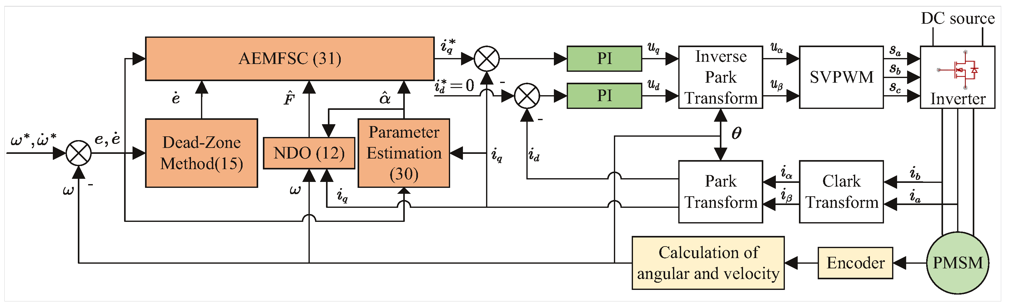
Figure 2.
Step responses of the four controllers: (a) . (b) . (c) .
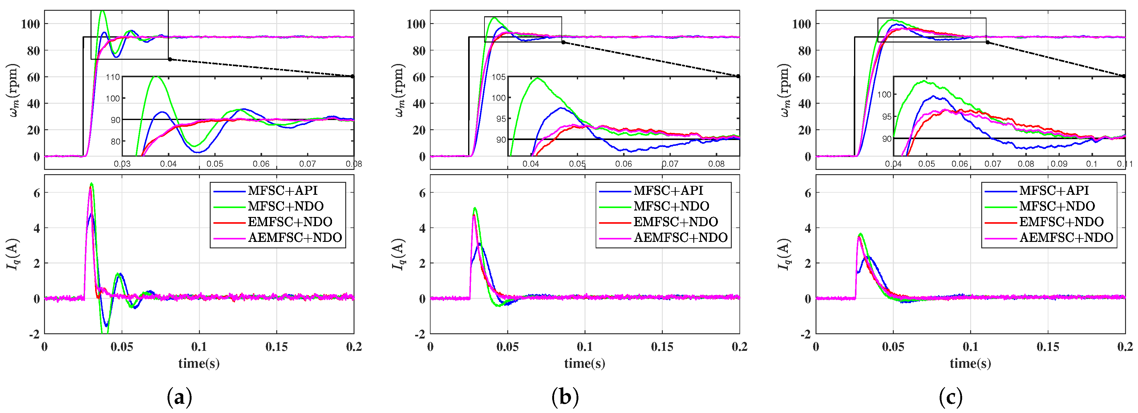
Figure 3.
Speed responses of the four controllers under load torque variations: (a) . (b) . (c) .
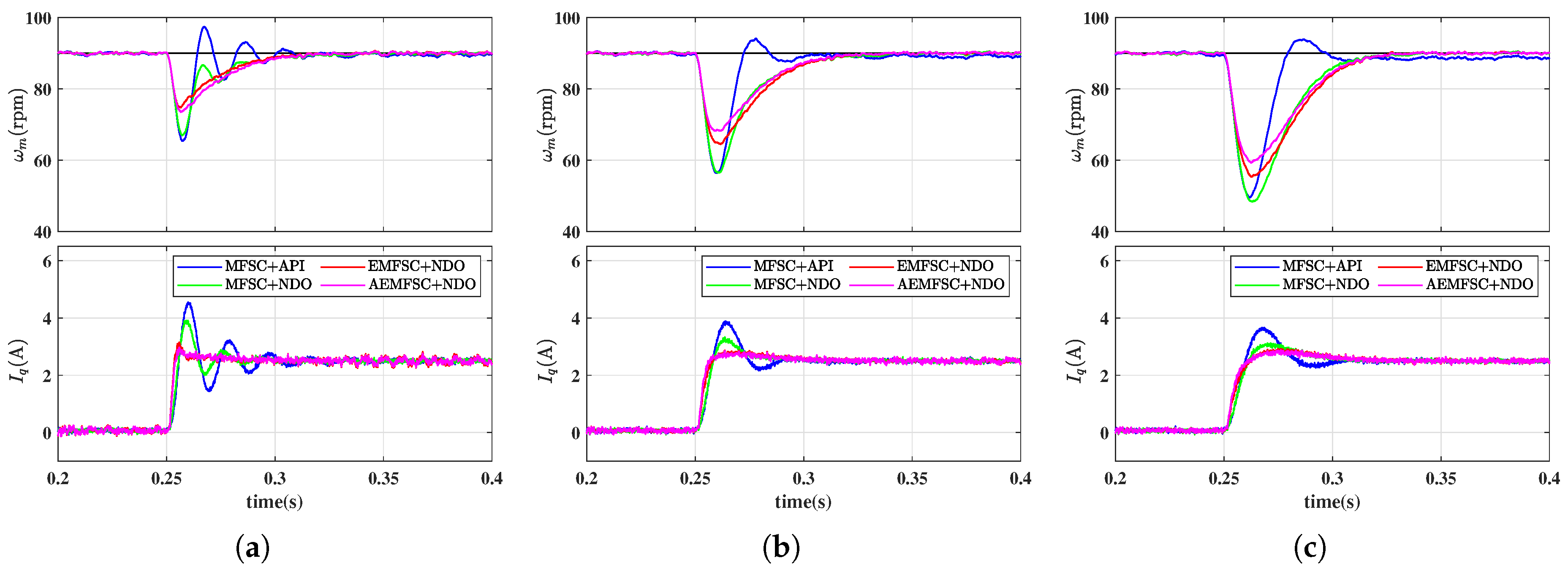
Figure 4.
Speed responses of the AEMFSC-NDO controller under square wave speed: (a) . (b) . (c) .
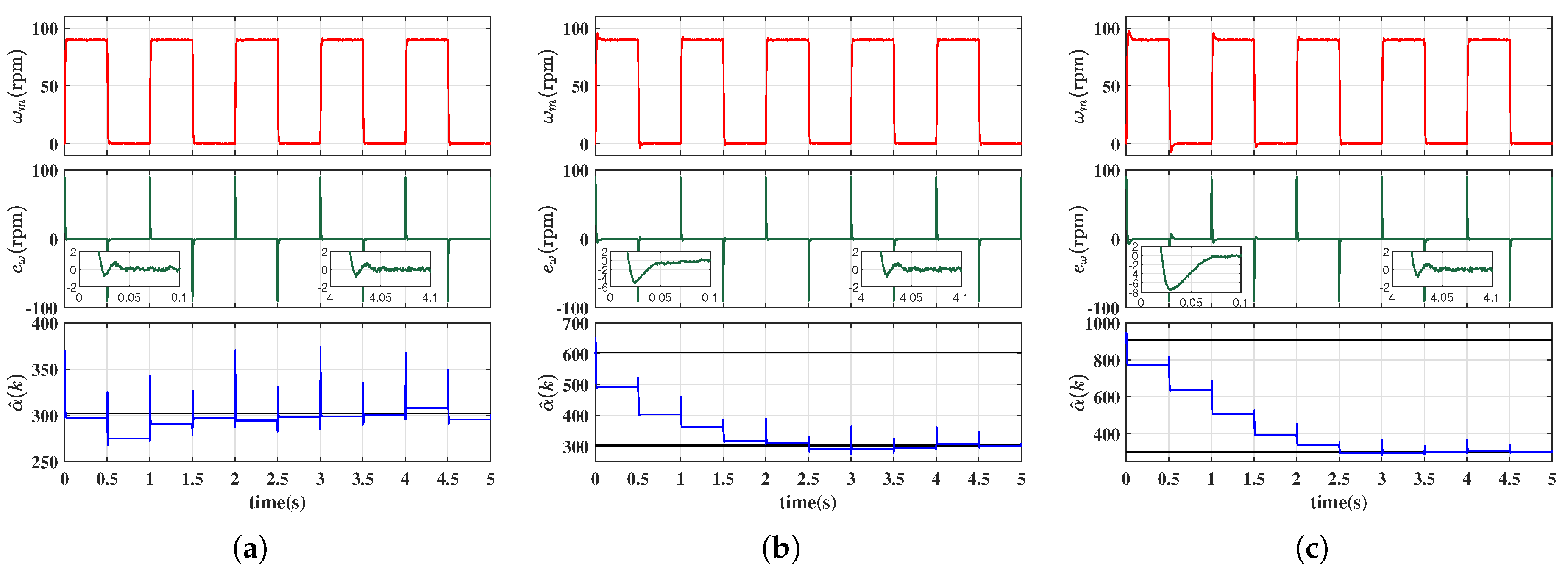
Figure 5.
Input gain identification results under square wave speed with three load conditions: (a) . (b) . (c) .
Figure 5.
Input gain identification results under square wave speed with three load conditions: (a) . (b) . (c) .
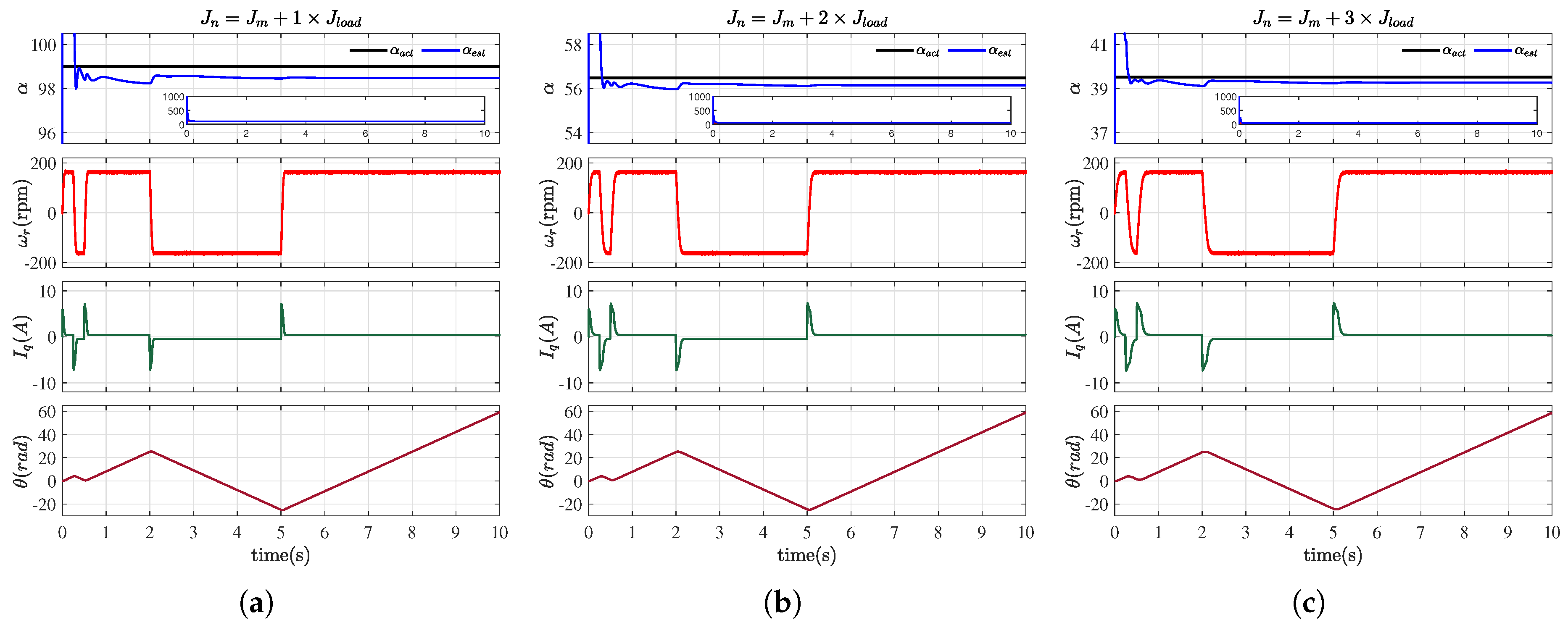
Figure 6.
Experimental platform of SMPMSM drive system.
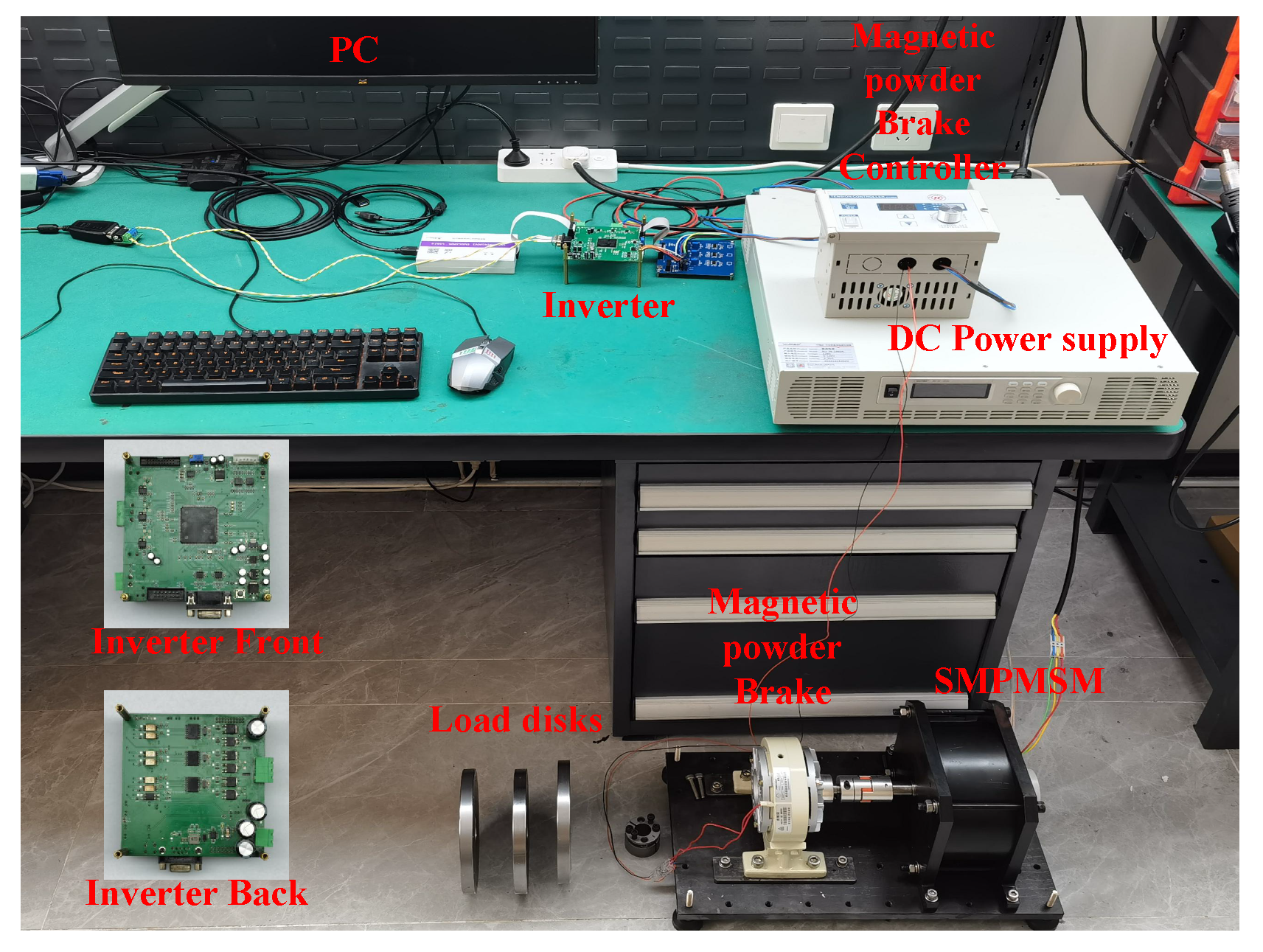
Figure 7.
Experimental identification of input gain : square wave speed tests under three load conditions (Triplicate Trials). (a) . (b) . (c) .
Figure 7.
Experimental identification of input gain : square wave speed tests under three load conditions (Triplicate Trials). (a) . (b) . (c) .
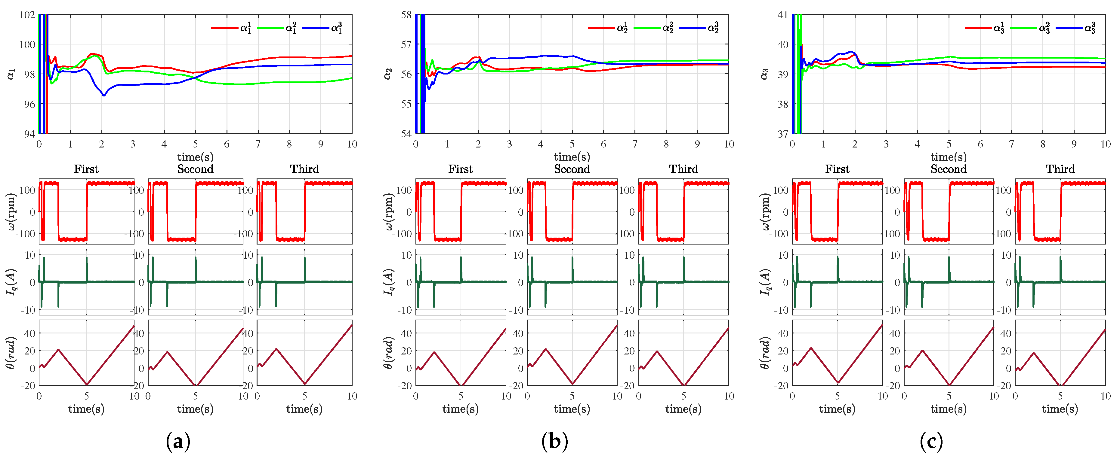
Figure 8.
Step responses of the four controllers: (a) . (b) . (c) .
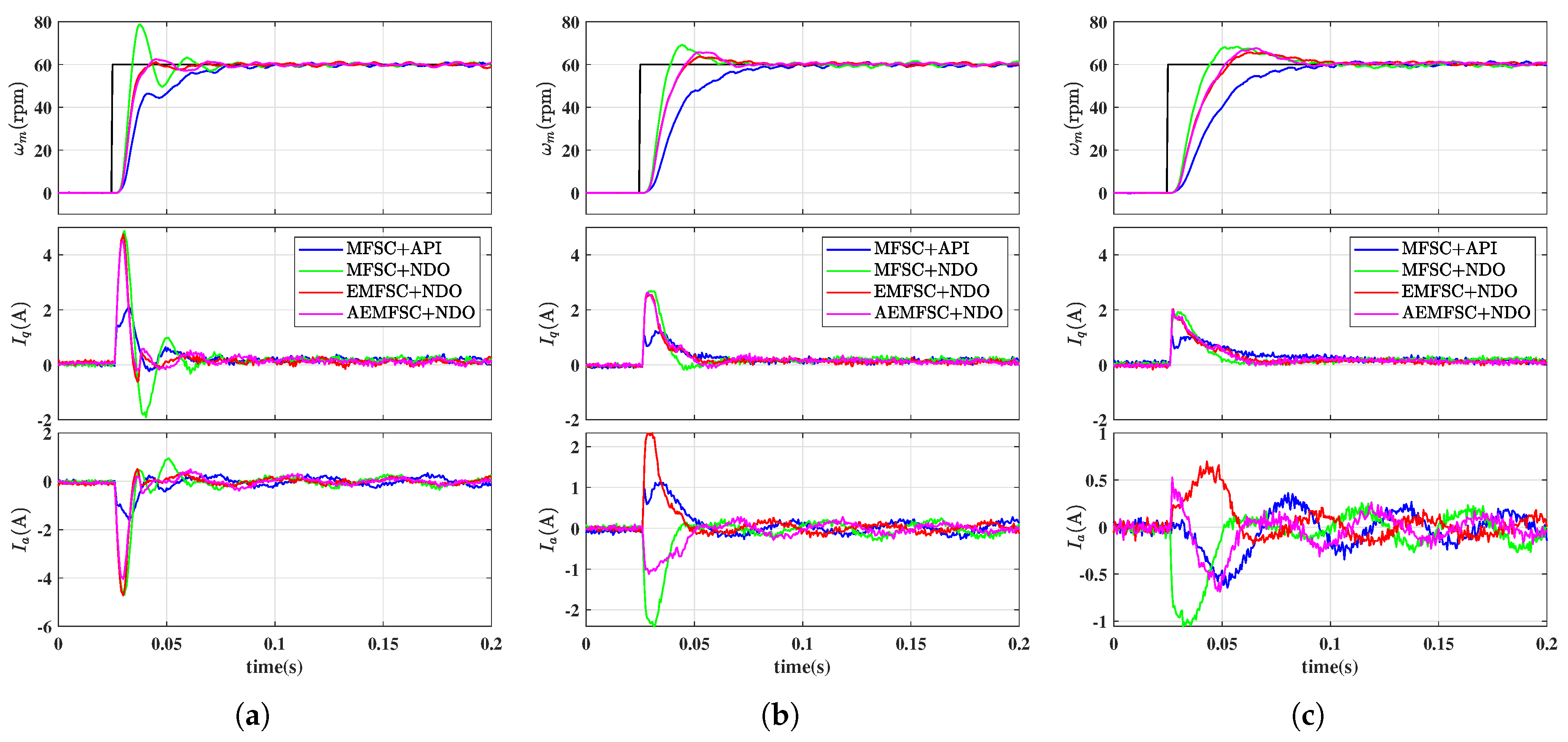
Figure 9.
Speed responses of the MFSC-API controller under load torque variations: (a) . (b) . (c) .
Figure 9.
Speed responses of the MFSC-API controller under load torque variations: (a) . (b) . (c) .
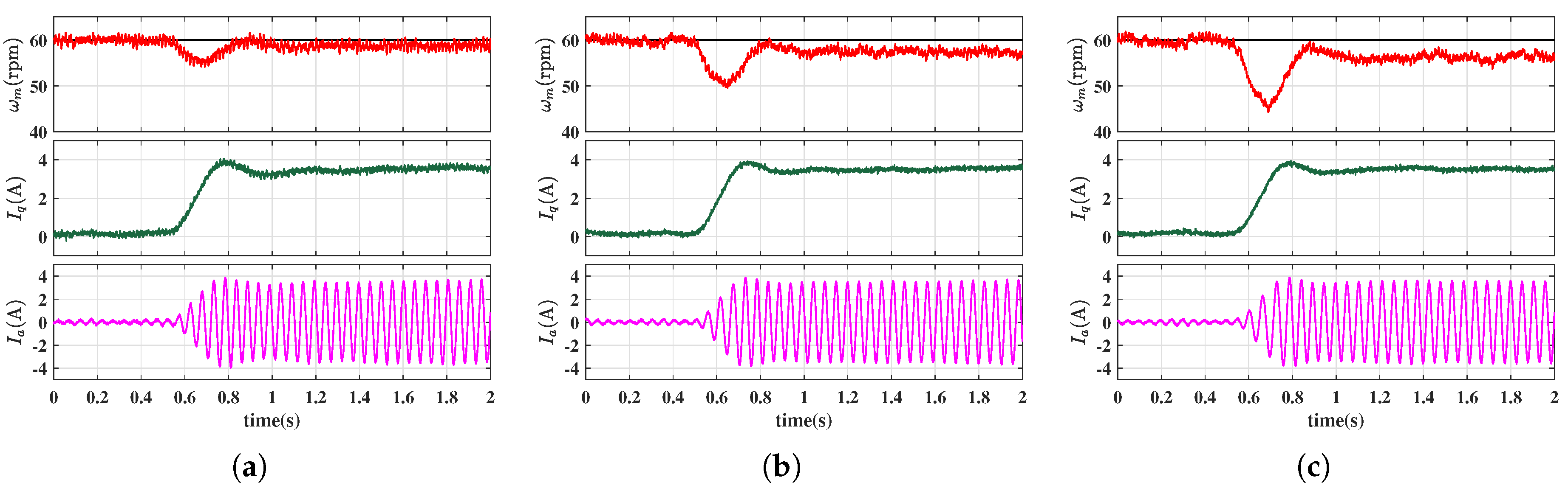
Figure 10.
Speed responses of the MFSC-NDO controller under load torque variations: (a) . (b) . (c) .
Figure 10.
Speed responses of the MFSC-NDO controller under load torque variations: (a) . (b) . (c) .
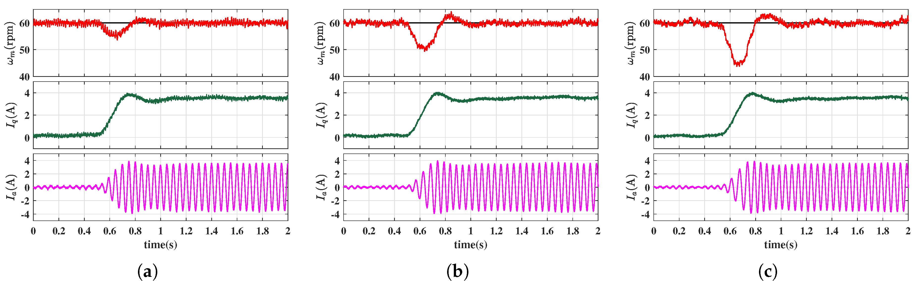
Figure 11.
Speed responses of the EMFSC-NDO controller under load torque variations: (a) . (b) . (c) .
Figure 11.
Speed responses of the EMFSC-NDO controller under load torque variations: (a) . (b) . (c) .
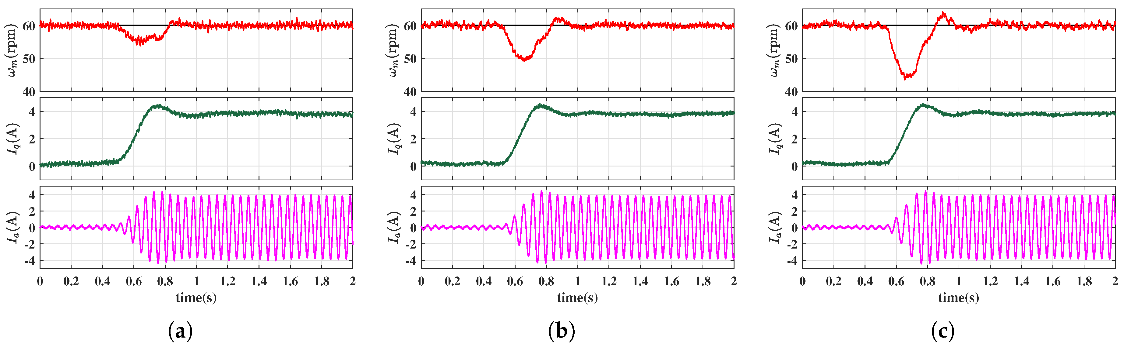
Figure 12.
Speed responses of the AEMFSC-NDO controller under load torque variations: (a) . (b) . (c) .
Figure 12.
Speed responses of the AEMFSC-NDO controller under load torque variations: (a) . (b) . (c) .
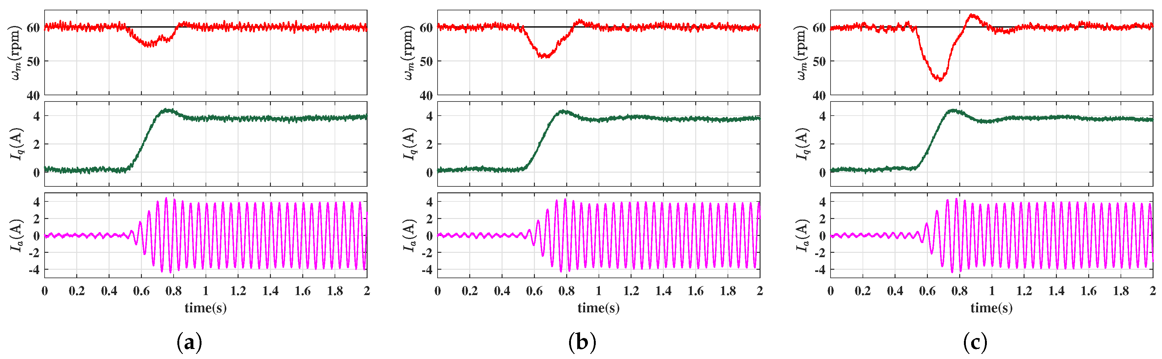
Figure 13.
Speed responses of the MFSC-API controller under square wave speed: (a) . (b) . (c) .
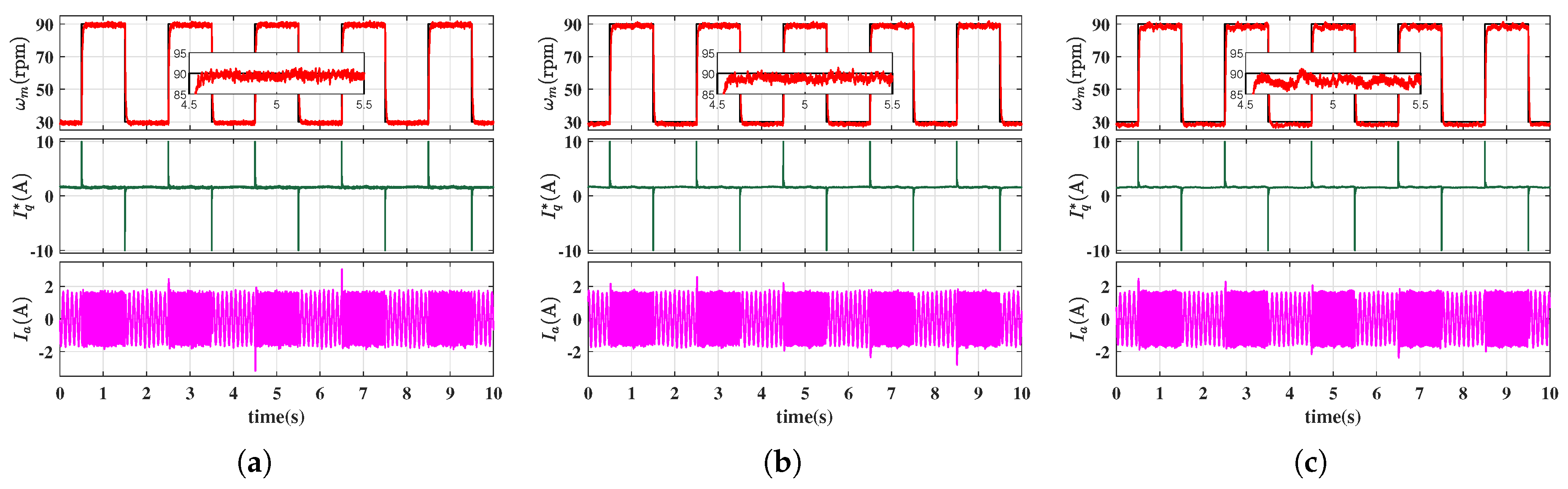
Figure 14.
Speed responses of the MFSC-NDO controller under square wave speed: (a) . (b) . (c) .
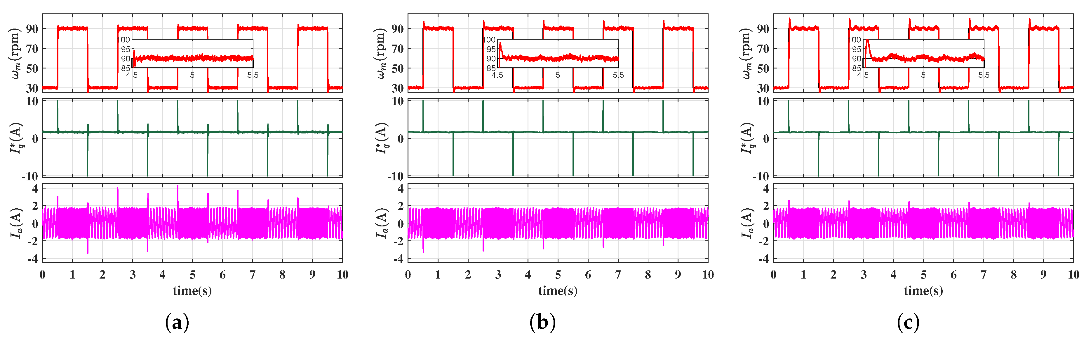
Figure 15.
Speed responses of the EMFSC-NDO controller under square wave speed: (a) . (b) . (c) .
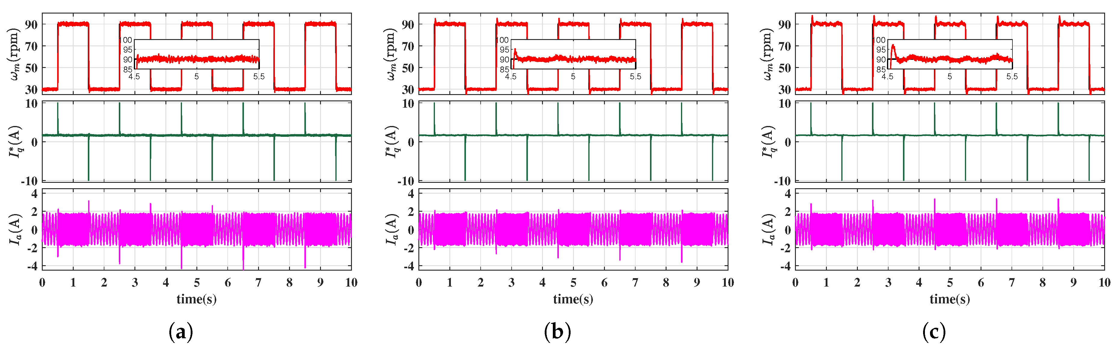
Figure 16.
Speed responses of the AEMFSC-NDO controller under square wave speed: (a) . (b) . (c) .
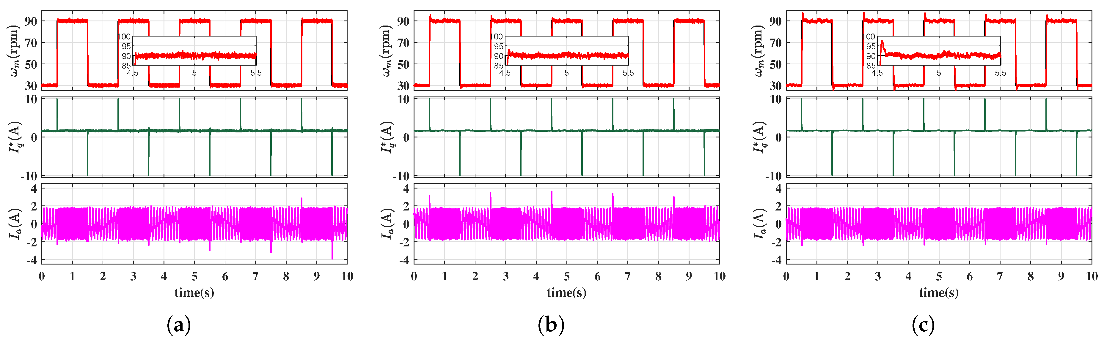
Figure 17.
Input gain adaptation results of the AEMFSC-NDO controller under square wave speed : (a) . (b) . (c) .
Figure 17.
Input gain adaptation results of the AEMFSC-NDO controller under square wave speed : (a) . (b) . (c) .
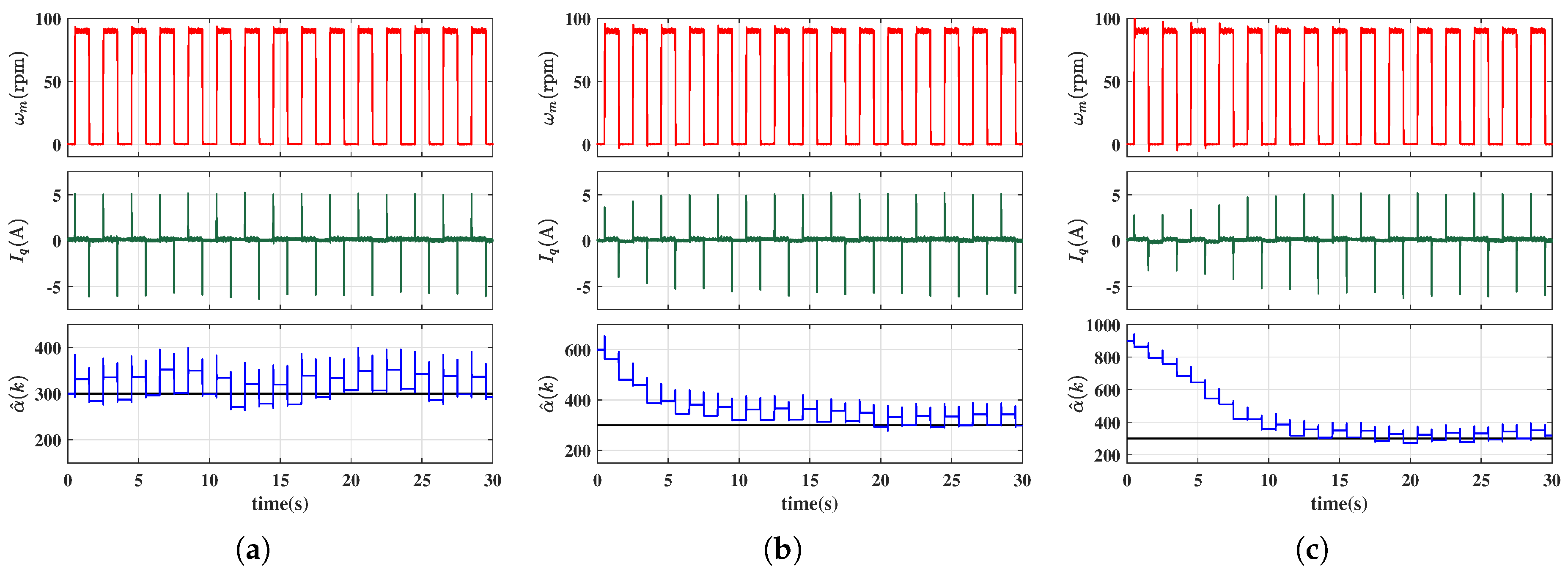

Table 1.
Specification of the SMPMSM
| Parameter description | Symbol | Value |
|---|---|---|
| DC-bus voltage | 34 V | |
| Rated voltage | 24 V | |
| No-Load Speed | N | 150 rpm |
| Peak locked torque | 10 N·m | |
| Peak locked current | 8 A | |
| Pole pairs | 20 | |
| Stator resistance | 1.8 | |
| Stator inductance | 6 mH | |
| Motor inertia | 0.00412 kg·m2 | |
| Permanent magnet flux | 0.05498 Wb |
Table 2.
Comparison of performance indices
| Controller | Speed overshoot(rpm) | Settling time(s) | ||||
| MFSC-API | 1.00 | 1.21 | 1.63 | 0.0710 | 0.0855 | 0.0895 |
| MFSC-NDO | 18.84 | 9.17 | 8.30 | 0.0485 | 0.0430 | 0.0630 |
| EMFSC-NDO | 1.43 | 3.64 | 5.72 | 0.0340 | 0.0520 | 0.0765 |
| AEMFSC-NDO | 2.52 | 5.74 | 7.62 | 0.0405 | 0.0455 | 0.0585 |
Table 3.
Comparison of performance indices
| Controller | Speed drop(rpm) | Settling time(s) | ||||
| MFSC-API | 5.89 | 10.41 | 15.66 | – | – | – |
| MFSC-NDO | 6.42 | 10.69 | 16.31 | 0.372 | 0.397 | 0.453 |
| EMFSC-NDO | 6.21 | 10.92 | 16.57 | 0.345 | 0.379 | 0.416 |
| AEMFSC-NDO | 5.90 | 9.20 | 16.02 | 0.3355 | 0.3675 | 0.4045 |
Table 4.
Comparison of performance indices
| Controller | Speed RMSE(rpm) | 30rpm IAE | 90rpm IAE | ||||||
| MFSC-API | 5.773 | 6.390 | 6.939 | 2.640 | 4.760 | 6.581 | 2.962 | 4.607 | 6.936 |
| MFSC-NDO | 4.784 | 5.185 | 5.548 | 1.629 | 1.700 | 1.795 | 2.215 | 2.341 | 2.881 |
| EMFSC-NDO | 4.772 | 5.018 | 5.525 | 1.608 | 1.645 | 1.669 | 2.203 | 2.345 | 2.516 |
| AEMFSC-NDO | 4.786 | 4.991 | 5.518 | 1.679 | 1.694 | 1.724 | 2.224 | 2.304 | 2.380 |
Disclaimer/Publisher’s Note: The statements, opinions and data contained in all publications are solely those of the individual author(s) and contributor(s) and not of MDPI and/or the editor(s). MDPI and/or the editor(s) disclaim responsibility for any injury to people or property resulting from any ideas, methods, instructions or products referred to in the content. |
© 2025 by the authors. Licensee MDPI, Basel, Switzerland. This article is an open access article distributed under the terms and conditions of the Creative Commons Attribution (CC BY) license (http://creativecommons.org/licenses/by/4.0/).
Copyright: This open access article is published under a Creative Commons CC BY 4.0 license, which permit the free download, distribution, and reuse, provided that the author and preprint are cited in any reuse.


