
Submitted:
05 May 2025
Posted:
07 May 2025
You are already at the latest version
Abstract
In recent years, novel Personal Mobility Vehicles (PMVs) with a narrow width and an inward tilting mechanism, similar to motorcycles (MCs), have been proposed to prevent overturning during turns. Due to their compact size, these vehicles have inherent limitations in collision safety, making their dynamic safety and accident avoidance capabilities particularly crucial. In this study, a comparative analysis was conducted using a simulated single lane change course to evaluate obstacle avoidance performance. The results reveal that PMVs equipped with an active inward tilting mechanism exhibit superior obstacle avoidance capabilities. Based on the roll moment equilibrium conditions of these vehicles, an investigation of vehicle states during avoidance maneuvers revealed that both actual and virtual tilt angles coexist in PMVs, and their combined equivalent tilt angle effectively balances the roll moment during turning. This unique mechanism, which integrates the responsiveness of passenger cars with motorcycle-like tire lateral force characteristics, underpins the exceptional obstacle avoidance capabilities of actively inward-tilting PMVs.
Keywords:
three wheeled personal mobility vehicles
; obstacle avoidance
; active inward tilt
; load transfer
1. Introduction
Personal Mobility Vehicles (PMVs) have a longstanding history as compact and efficient transportation options. A novel type of PMV has recently emerged, resembling motorcycles in their ability to narrow their width and tilt inwards during turns to prevent tipping [1,2,3,4]. While these small vehicles offer enhanced maneuverability, they present challenges in terms of collision safety, highlighting the critical role of dynamic stability for accident avoidance. However, due to the novelty of this concept, research on the dynamic characteristics of such PMVs is limited, especially concerning their dynamic mechanisms during inward tilting while turning.
The authors have consistently conducted research on PMVs equipped with two front wheels and one rear wheel that can tilt actively [5,6,7,8,9,10,11,12,13,14]. They have explored their motion characteristics and provided mechanical design guidelines. This paper aims to clarify the dynamic obstacle avoidance capability of these narrow-track PMVs, which tilt inwards during turns. The clarification is achieved through theoretical and computational analyses by comparing these PMVs with conventional automobiles and motorcycles.
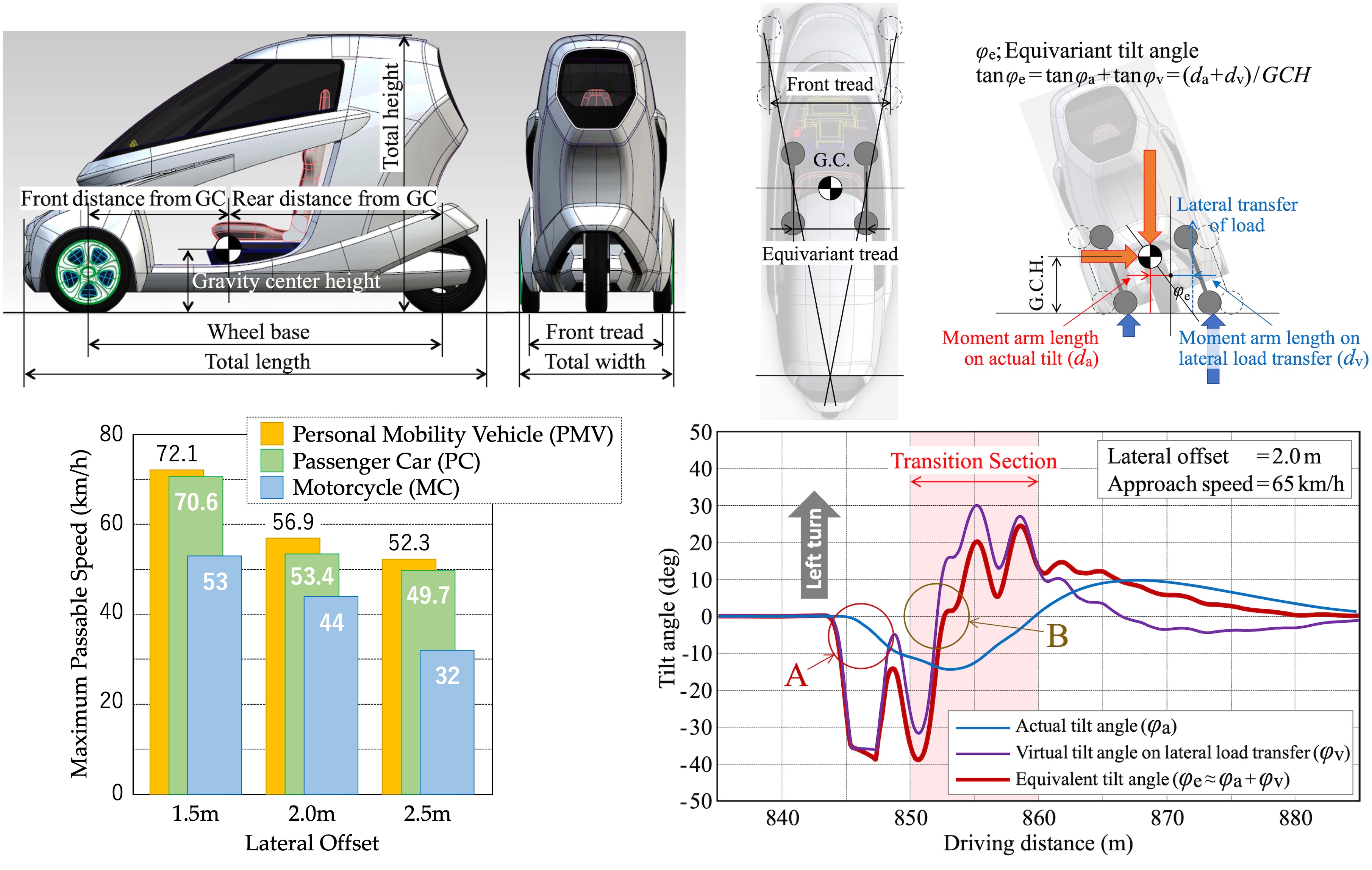
Figure 1 and Table 1 provide details about the model vehicle specifications. For our study, we utilized the simulation tool CarMaker [15] from the German company IPG to build a vehicle model with two front wheels. Since CarMaker is designed for four- wheeled passenger cars, we made the following adjustments during the modeling process:
- To simulate the single rear wheel, we positioned two rear wheels width-wise at the vehicle’s center. One of these wheels was designated as a dummy wheel with zero mass and zero tire forces.
- To achieve inward tilting during turns, we employed CarMaker’s active stabilizer function to apply an active anti-roll torque that induces the desired tilt. This anti-roll torque acts as an internal force within the vehicle system and does not directly affect external forces like tire forces. This approach, as shown in Figure 2, does not hinder the examination of motion characteristics and their mechanisms.
2. Vehicle Model
The model vehicle’s mass and inertial distribution are outlined in Table 1, and a simplified suspension mechanism is employed, as illustrated in Figure 3.
- We opted not to use realistic suspension mechanism models available in CarMaker. Instead, we employed a one-degree-of-freedom sliding mechanism for both front and rear wheels, incorporating moderate linear spring constants and damping characteristics (Table 2).
- The active stabilizer function is used as a simple addition of anti-roll torque, without simulating a realistic stabilizer structure.
- Tire force characteristics are defined through a characteristic map determined solely by ground load, slip angle, and camber angle, as shown in Figure 4. This characteristic map, adapted from motorcycle tire characteristics, does not account for tire force time delay.
- We did not consider the lateral shift of the ground contact center due to tire camber angle in this study.
2.1. Target Tilt Angle
In motorcycles, an inward tilt angle is generated during turning to balance the roll moment induced by centrifugal force. In this scenario, motorcycles primarily rely on the camber thrust force generated by tire camber angles associated with this inward tilt angle to execute the turn. As a result, tire slip angles during turning are extremely small. More precisely, minor slip angles, either positive or negative, may arise due to tire lateral force characteristics and rider posture (lean-in or lean-out). This report assumes that the PMV also employs motorcycle tires, and therefore, similar to motorcycles, the PMV is designed to generate an inward tilt angle of a magnitude that balances the roll moment induced by centrifugal force during turning.
Figure 5 illustrates the behavior of a PMV executing a turn without slip angles. The turning radius is determined geometrically by the steering angle (Equation (1)), and as indicated by Equation (2), the lateral acceleration during the turn is uniquely determined by both the steering angle and the vehicle speed. Furthermore, as indicated in Equation (3), the inward tilt angle required to balance the roll moment induced by centrifugal force is also uniquely determined.
PLA: prospected lateral acceleration v: vehicle speed; TTA: target tilt angle g: gravitational acceleration
2.2. Active Tilt Angle Tracking Control
The active inward tilt angle is provided by the active stabilizer function. This active stabilizer generates an anti-roll torque using a general PID tracking control shown in Figure 6, with Equation (3) as the target inward tilt angle. The active stabilizer function adds the vertical couple loads on the left and right wheels. By comparing the target inward tilt angle with the actual inward tilt angle, the vertical loads on the wheels are adjusted accordingly. When the actual inward tilt angle matches the target, the vertical loads on the wheels provided by the active stabilizer become zero. At this time, the roll moment induced by centrifugal force is balanced by the inward tilt angle, resulting in no left-right difference in ground load.
The PID control parameters (P, I, D) are determined through experimentation. In this study, the authors utilize results from previous research [6] on dynamic stability preservation, setting Kp = 4000, Ki = 50, and Kd = 0 for further investigation.
3. Driver Model
3.1. IPGDriver
In the simulations for both PMV and passenger car, automated driving was conducted using the IPGDriver included with CarMaker. IPGDriver is a component of the virtual vehicle system that autonomously selects driving speed and trajectory within a controlled course based on the forward 2nd order prediction model, recognizing the vehicle’s motion characteristics.
The standard parameters for the driver model, which should generally be set, and the switching points for the maneuver-based driver model, configured according to the driving conditions, are presented in Table 3.
From a run-up section of over 800m, the vehicles enter a controlled single lane change course. While the control of the longitudinal speed remains consistently automated, the lateral control switches from a straight-line driving model to automated driving. The straight-line driving model maintains travel along the center of the lane, while automated driving employs a narrower course width, allowing for advantageous path selection (feint steering) within the available range. As a result, the transition from the straight-line driving model to automated driving occurs after entering the controlled single lane change course.
The timing of this transition is set to be early enough upon entering the transition zone to avoid hitting the inner pylon, but late enough to not have the flexibility for path selection. Although the timing of the transition varies depending on the entry speed, by using the switching points indicated in Table 3, it was possible to conduct avoidance maneuvers in automated driving without the need for feint steering.
3.2. Rider Model in BikeSim
In the simulations for motorcycles, the rider model included with BikeSim was utilized, and a target trajectory was provided to simulate the motorcycle traveling on a course similar to that of the PMV.
4. Simulated Obstacle Avoidance Course
For simulating obstacle avoidance maneuvers, we employed a single lane change course as depicted in Figure 7. When comparing vehicles with significantly different widths, it is necessary to adjust the course width and avoidance width settings according to the study’s objectives. In this report, focusing on the dynamic safety of narrow-width PMVs during accident avoidance, although the conditions imposed might appear overly stringent in the real world, the most severe conditions were considered, and the following settings were chosen:
- When a vehicle is along the left edge of the road, we assume a certain protrusion width from the left road edge that the vehicle must avoid. Regardless of vehicle width, the same width of protrusion must be avoided.
- This study envisions scenarios where PMVs travel along the left road edge and avoid obstacles with minimal lane departure. Considering the lane width specified by Japan’s Road Structure Law (2.75m to 3.5m), an avoidance width of 2.0m was chosen after confirming avoidance capability superiority within a range of 1.5m to 2.5m. For passenger cars under the same conditions, deviation into the opposite lane is unavoidable.
- In CarMaker’s autonomous driving, the lane width was set as the vehicle width plus 0.62m regardless of the vehicle’s width to eliminate the advantage of narrower PMVs based on lane width tolerance.
- Anticipating avoidance maneuvers near Japan’s legal speed limits, a 10m avoidance section length was determined based on CarMaker simulations for approximately 60km/h.
5. Comparison of Maximum Passable Speeds
Standard vehicle models available in CarMaker and BikeSim (from the US company Mechanical Simulation) were used for the passenger car and motorcycle respectively, with key specifications outlined in Table 4. The maximum passable speeds of the PMV, passenger car, and motorcycle on the course depicted in Figure 7 are presented in Figure 8. While the PMV and passenger car results are based on the same CarMaker, ensuring a fair comparison, the motorcycle results are borrowed from Bike Sim, thus not entirely equitable.
As well known, the obstacle avoidance capabilities of motorcycles are significantly inferior to those of passenger cars. This is because passenger cars produce avoidance maneuvers in the sequence of straight-line - steering - tire slip angle - lateral force, allowing substantial lateral force to be obtained promptly after steering, without significant delay. In contrast, motorcycles generate avoidance maneuvers in the sequence of straight-line - slight counter steering - inward roll moment - inward tilt angle - tire camber angle - camber thrust. As a result, the lateral force required for turning becomes obtained only after substantial body roll motion. This observation aligns well with the considerably lower passable speed of motorcycles, as depicted in Figure 8.
As shown in Figure 8, the inward-tilting PMV achieves even higher speeds than the passenger car, indicating superior dynamic safety for accident avoidance. Here, the PMV that tilts inward is showing significantly different results from the motorcycle that leans inward in the same way. Therefore, clarifying the mechanism behind the high obstacle avoidance capability of the tilting PMV can be of great value.
6. Equilibrium of Mechanical Roll Moment
First, we consider the balance of mechanical roll moment to understand the state of each vehicle during the initial steering phase.
6.1. Equilibrium of the Roll Moment of a Four-Wheeled Passenger Car During Turning
Figure 9 illustrates the load transfer during turning from a rear-view perspective. Equation (4) represents the load transfer to the outer wheels during turning, while Equation (5) describes the relationship between lateral acceleration and the vertical loads on each wheel. For simplicity, it is assumed that the front-to-rear distribution of roll moment and the roll stiffness distribution due to the suspension are equal. The effects of unequal roll stiffness distribution and other related factors are detailed in the authors’ previous study [14].
According to Equations (5.1) and (5.3), the turning lateral acceleration at which the inner wheel load becomes zero is calculated to be 1.31G. This indicates that the likelihood of the vehicle tipping over solely due to lateral acceleration during turning is low.
6.2. Equilibrium of the Roll Moment of a Three-Wheeled PMV During Turning
In a front-two-wheel, rear-one-wheel PMV, the effective tread width (Tr) during steady-state turning is defined at the lateral cross-section of the center of gravity, as shown in the top-view diagram in Figure 10(a).
Figure 10(b) illustrates the load transfer during turning from a rear-view perspective. Equation (6) represents the tread width (Tr), while Equation (7) describes the load transfer to the outer wheel during turning. Equation (8) shows the relationship between lateral acceleration and vertical loads on each wheel.
Using Equation (8.1), the limit lateral acceleration for tipping over (rollover) with the given parameters in Table 1 is calculated to be 0.68G. This is significantly smaller than the tipping limit of 1.31G for the four-wheeled passenger car derived in Section 6.1. Without the tilting mechanism, the vehicle has high risk to tipping (rolling over) due to the lateral acceleration during turning.
Next, consider the time when the avoidance phase has progressed and an inward tilt that is just balanced with the lateral acceleration has occurred.
Figure 11 illustrates the load condition of a PMV with a tilting mechanism during turning, viewed from the rear. In steady-state cornering, the body’s inward tilt ensures that there is no difference in ground loads between the two front wheels. The even distribution of ground loads between the front wheels remains unchanged. Compared to the non-tilting PMV, the front wheels have an even greater margin in tire capacity.
When the avoidance phase has progressed and an inward tilt that is just balanced with the lateral acceleration has occurred, the ground load of each wheel is expressed by Equation (9). In this relationship, the phenomenon of the tire losing the ground load does not occur regardless of the lateral acceleration that has occurred. This shows the extremely high turning limit capability of the PMV with an inward tilt mechanism.
Since there is no difference in ground loads between the two front wheels during turning (FzfL = FzfR), the vehicle is essentially resistant to tipping (rollover) during turns and possesses an extremely high lateral acceleration limit.
6.3. Equilibrium of the Roll Moment of a Motorcycle During Turning
In motorcycles with single wheels at both the front and rear, load transfer as seen in passenger cars (discussed earlier) or in PMVs does not occur. In fact, the vehicle cannot generate lateral acceleration until the body leans inward. As a result, the yaw response of motorcycles is extremely sluggish. Although a motorcycle can exhibit high cornering capability, comparable to that of a PMV, when it is turning with an inward lean that precisely balances the lateral acceleration, its obstacle avoidance performance must be considered quite poor due to its inherently slow yaw response.
7. Understanding Vehicles States on Dynamic Simulation
7.1. Passenger Car Vehicle State
Figure 12 shows steering angle, lateral acceleration, and corresponding tire ground load of the passenger car during the single lane change course. Lateral acceleration lags slightly behind the steering angle, yet there’s no noticeable delay between lateral acceleration and tire ground load changes. This implies that the outward roll moment due to centrifugal force is balanced by an inward roll moment resulting from transferring ground load from the inner wheel to the outer wheel. In other words, it can be said that the lateral shift of the neutral point of ground load generates a virtual tilt angle comparable in magnitude to the lean angle observed in motorcycles as shown in Figure 13.
7.2. PMV Vehicle State
Next, Figure 14 presents the steering angle, lateral acceleration, and corresponding tilt angle of the PMV during the single lane change course. Notably, the tilt angle that should balance the outward roll moment due to centrifugal force is significantly delayed relative to lateral acceleration (Figure 14, section A). Considering the passenger car behavior in Figure 12, at the beginning of steering, the outward roll moment resulting from centrifugal force should be complemented by a virtual inward tilt angle arising from the transition of tire ground load from inner to outer. Figure 15 illustrates the lateral acceleration and the responsive load transition of tire ground load (Figure 15, section A).
Following the example of Figure 13, Figure 16 illustrates the actual inward tilt angle of the PMV and the virtual inward tilt angle resulting from the transition of tire ground load between inner and outer wheels. In the case of the three-wheeled PMV, the virtual inward tilt angle resulting from the transition of tire ground load needs to be derived by converting it to an equivalent tread at the center of gravity position.
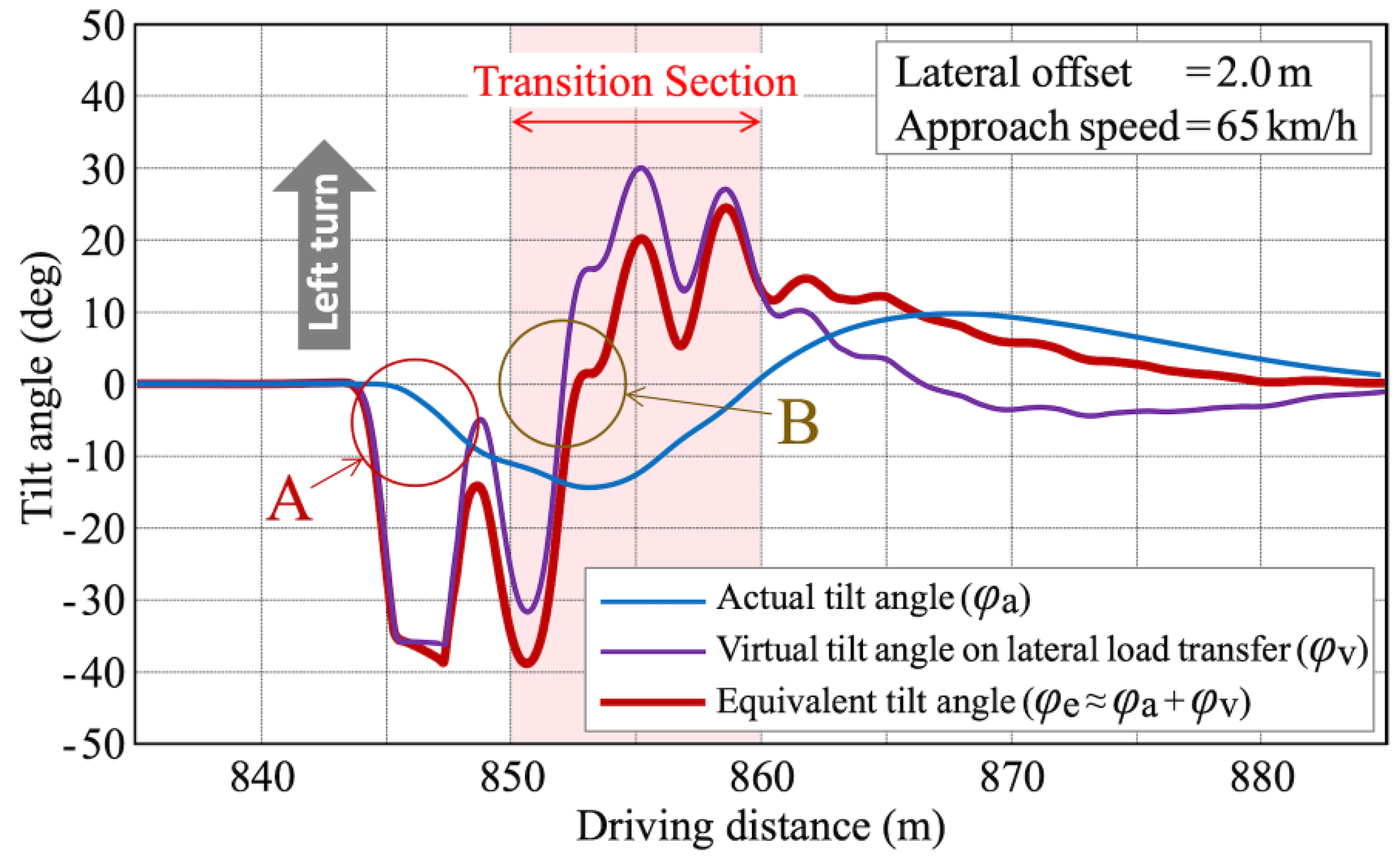
Figure 17 presents the actual tilt angle and the virtual tilt angle resulting from the transition of tire ground load, and the equivalent combined inward tilt angle (actual tilt angle + virtual tilt angle).
8. Discussion
In motorcycles, roll moments are balanced by the actual lean angle, while in passenger cars, equilibrium results from the virtual tilt angle arising from ground load transfer. For PMVs, observing Figure 16, both actual and virtual tilt angles coexist, combining to balance the outward roll moment induced by centrifugal force.
In the initial steering phase of the PMV (Figure 17, section A), lateral forces behave similarly to passenger cars, i.e., lateral forces are generated without significant delay due to slip accompanying steering input, and the outward roll moment induced by centrifugal force is balanced by mainly the transfer of ground load from the inner front wheel to the outer front wheel. This contrasts with motorcycles, as discussed in Section 5, and results in passenger car- like responsiveness.
Upon entering the avoidance section (Figure 17, section B), the inward roll moment generated by the actual tilt angle balances the outward roll moment induced by centrifugal force, and the transfer of ground load between the front wheels is resolved. The lateral force required for turning, akin to the mechanism of motorcycles, is provided by the camber thrust force resulting from the tire camber angle associated with the inward tilt. It is known that the lateral forces generated by tire slip angles exhibit saturation characteristics relative to the tire ground load and the sum of lateral forces generated by the left and right wheels also saturates in response to the transferring tire ground load from inner to outer [12]. However, in the case of PMVs, similar to motorcycles, it can be said that they do not possess such saturation characteristics for lateral forces, resulting in higher lateral force limits.
In summary, actively inward-tilting PMVs integrate the responsiveness of passenger cars with the high tire lateral force of motorcycles, which contributes to their superior obstacle avoidance capabilities.
9. Future Works
Although in real-world scenarios obstacle avoidance typically involves braking, this paper focused solely on steering-based avoidance for the sake of simplicity. In obstacle avoidance maneuvers that include braking, the temporal allocation between deceleration and lateral acceleration caused by steering leads to changes in tire ground loads, which in turn affect the size of the friction circle.
This interacts in a complex manner with the phenomena detailed in this paper, namely the redistribution of front wheel ground loads during initial steering and the cancellation of roll moments due to inward leaning. Future research will examine the roll moment equilibrium while taking deceleration into account, and, based on that, conduct dynamic simulation analyses to investigate the obstacle avoidance capabilities of PMVs with an active tilting mechanism and a two-front, one-rear wheel configuration in greater detail.
10. Conclusions
Comparative analysis conducted on a simulated single lane change course for obstacle avoidance maneuvers has revealed that PMVs equipped with an active inward-tilting mechanism possess superior obstacle avoidance capabilities not only compared to motorcycles but also surpassing those of passenger cars. Examination of the vehicle states during these maneuvers demonstrates that in PMVs, both actual and virtual tilt angles coexist, with their combined equivalent tilt angle balancing the roll moment during turns. This unique mechanism, integrating passenger car responsiveness and motorcycle-like tire lateral force, underpins the high obstacle avoidance capabilities of actively inward-tilting PMVs.
Author Contributions
Conceptualization, T.H.; formal analysis, T.H.; methodology, T.H. and T.K.; supervision, I.K.; validation, T.H.; writing—original draft, T.H.; writing—review and editing, T.H.
Funding
This research received no external funding.
Conflicts of Interest
The authors declare no conflict of interest.
References
- Haraguchi, T. 4. Personal Mobility Vehicle (J). Mobility Service, Mobility Innovation Series, Vol. 1. Corona Publishing Co., Ltd., Tokyo, Japan. 2020, 92-123. ISBN 978-4-339- 02771-6.
- Haraguchi, T. Prospects of Future Personal Mobility (PMV) from a Historical Perspective (J). Cutting-edge Automotive Technology, Monthly Automotive Technology, Technical Information Institute Co., Ltd., Tokyo, Japan. 2020. ISSN2432-5694.
- Goto, K.; Murayama, H. Lean motion dynamics of a tilting personal mobility with the suspension device equipped with a mechanism converts driver’s actuation force into lean moment (J): Transactions of the JSME. 2019, Vol.85 No.875, pp.19-00034. [CrossRef]
- Araki, K.; Gwak, J.; Sugimachi, T.; Kubo, N.; Suda, Y. Control method to improve posture stability of narrow tilting vehicles. International Journal of Intelligent Transportation System Research. 2022, Vol.20, pp.204-211. [CrossRef]
- Haraguchi, T.; Kaneko, T.; Kageyama, I.; Kuriyagawa, Y.; Kobayashi, M. Study of Tilting Type Personal Mobility Vehicle by the Immersive Driving Simulator with Five Large Screens (J). Transactions of Society of Automotive Engineers of Japan. 2017, Vol.48 No.3, pp.693-698, 20174447.
- Haraguchi, T.; Kageyama, I.; Kaneko, T. Inner Wheel Lifting Characteristics of Tilting Type Personal Mobility Vehicle by Sudden Steering Input (J). Transactions of Society of Automotive Engineers of Japan. 2019, Vol.50 No.1, pp.96- 101, 20194038.
- Kaneko, T.; Kageyama, I.; Haraguchi, T. A Study on Characteristics of the Vehicle Response by Abrupt Operation and an Improvement Method for Personal Mobility Vehicle with Leaning Mechanism (J). Transactions of Society of Automotive Engineers of Japan. 2019, Vol.50 No.3, pp.796-801, 20194345.
- Haraguchi, T.; Kageyama, I.; Kaneko, T. Study of Personal Mobility Vehicle (PMV) with Active Inward Tilting Mechanism on Obstacle Avoidance and Energy Efficiency. Applied Sciences, Multidisciplinary Digital Publishing Institute (MDPI), Appl. Sci. 2019, 9, 4737. [CrossRef]
- Haraguchi, T.; Kaneko, T.; Kageyama, I. Steering Torque Characteristics of Personal Mobility Vehicle (PMV) with Inward Tilting Mechanism (J). Transactions of Society of Automotive Engineers of Japan. 2020, Vol.51 No.5, pp.931- 937, 20204471.
- Haraguchi, T.; Kaneko, T.; Kageyama, I. A Method to Minimize Steering Disturbance Caused by Vertical Load Reaction Force of Personal Mobility Vehicle (PMV) with Inward Tilting Mechanism (J). Transactions of Society of Automotive Engineers of Japan. 2021, Vol.52 No.2, pp.462-468, 20214197.
- Haraguchi, T.; Kaneko, T.; Kageyama, I. Steering Torque Hysteresis of Personal Mobility Vehicle (PMV) with Inward Tilting Mechanism (J). Transactions of Society of Automotive Engineers of Japan. 2021, Vol.52 No.5, pp.987-993, 20214638.
- Haraguchi, T.; Kaneko, T.; Kageyama, I. A Study of Steer Characteristics of Personal Mobility Vehicle (PMV) with Inward Tilting Mechanism (J). Transactions of Society of Automotive Engineers of Japan. 2022, Vol.53 No.1, pp.58- 64, 20224033.
- Haraguchi, T.; Kaneko, T. Design Requirements for Personal Mobility Vehicle (PMV) with Inward Tilt Mechanism to Minimize Steering Disturbances Caused by Uneven Road Surface. Inventions, Multidisciplinary Digital Publishing Institute (MDPI), Inventions. 2023, 8, 37. [CrossRef]
- Haraguchi, T.; Kaneko, T. Study on the Body Torsional Rigidity of Personal Mobility Vehicles (PMVs) with Active Tilting Mechanisms (J). Transactions of Society of Automotive Engineers of Japan. 2025, Vol.56 No.2, pp.366-373, 20254124.
- CarMaker: Virtual Testing of Automobiles and Light-Duty Vehicles, IPG Automotive GmbH. Available online: https://ipg-automotive.com/products-services/simulation-software/carmaker/ (accessed on 20 October 2019).
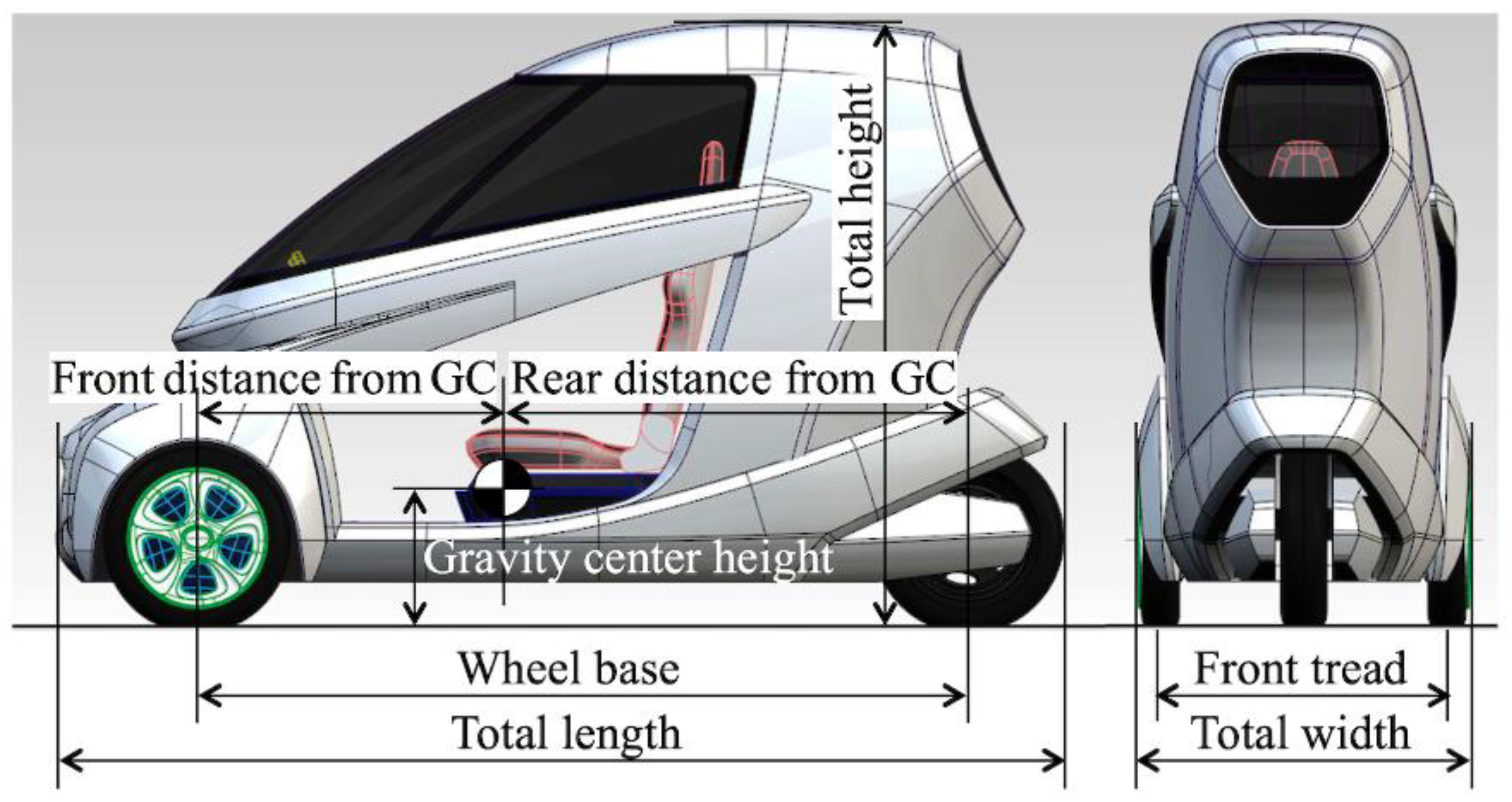
Figure 2.
Active inward tilting mechanism on CarMaker.
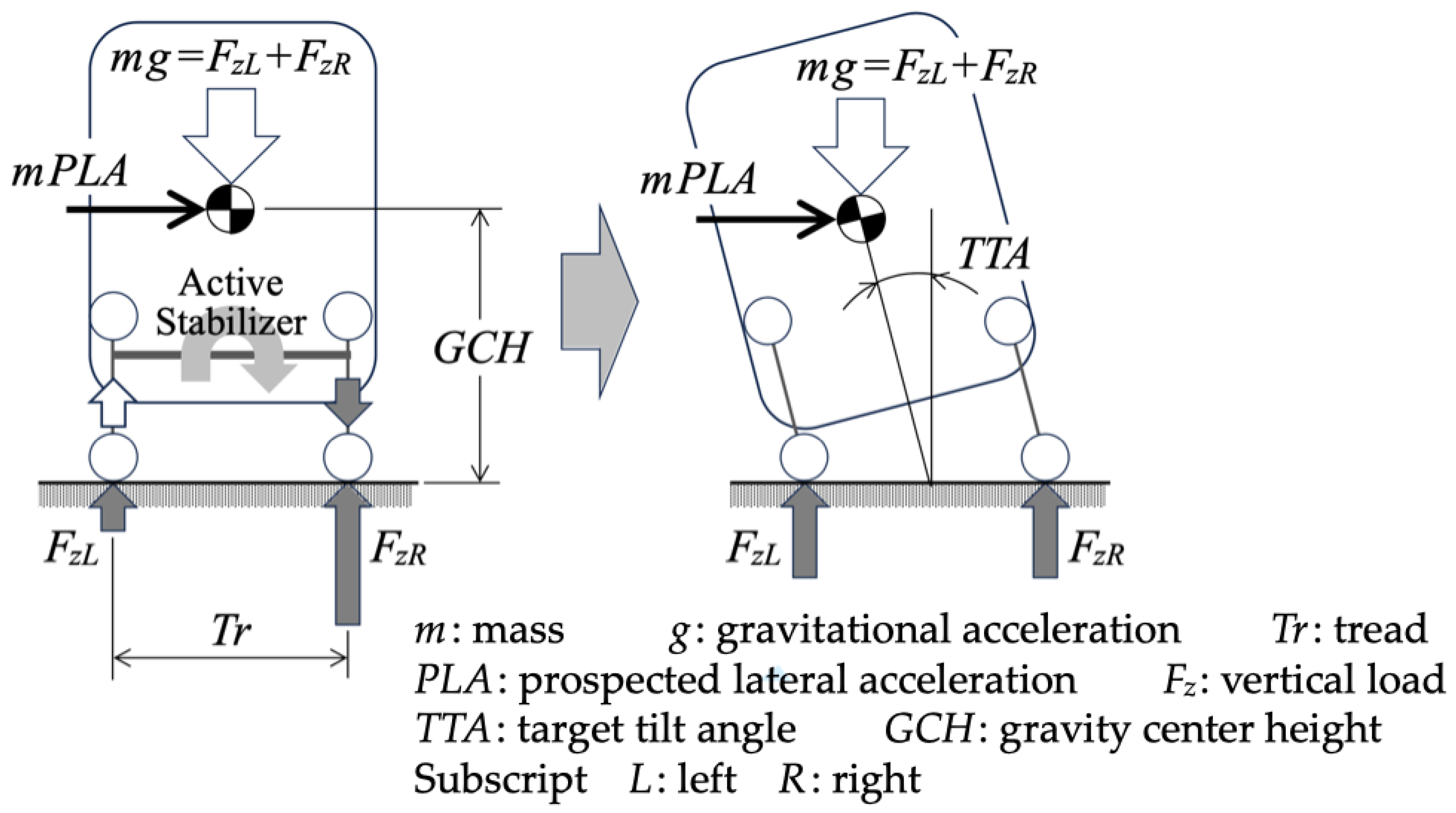
Figure 3.
Simplified suspension model on CarMaker.
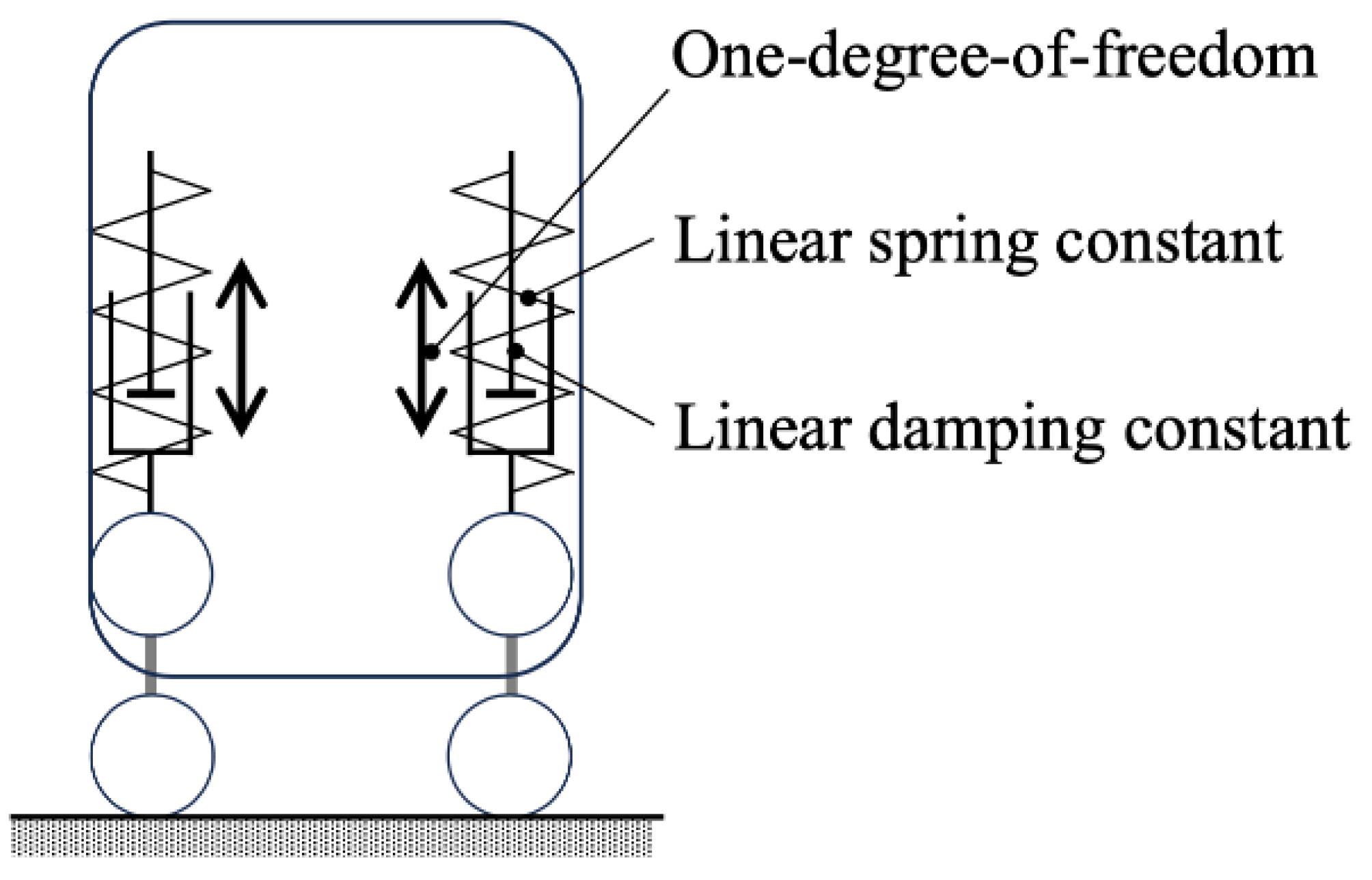
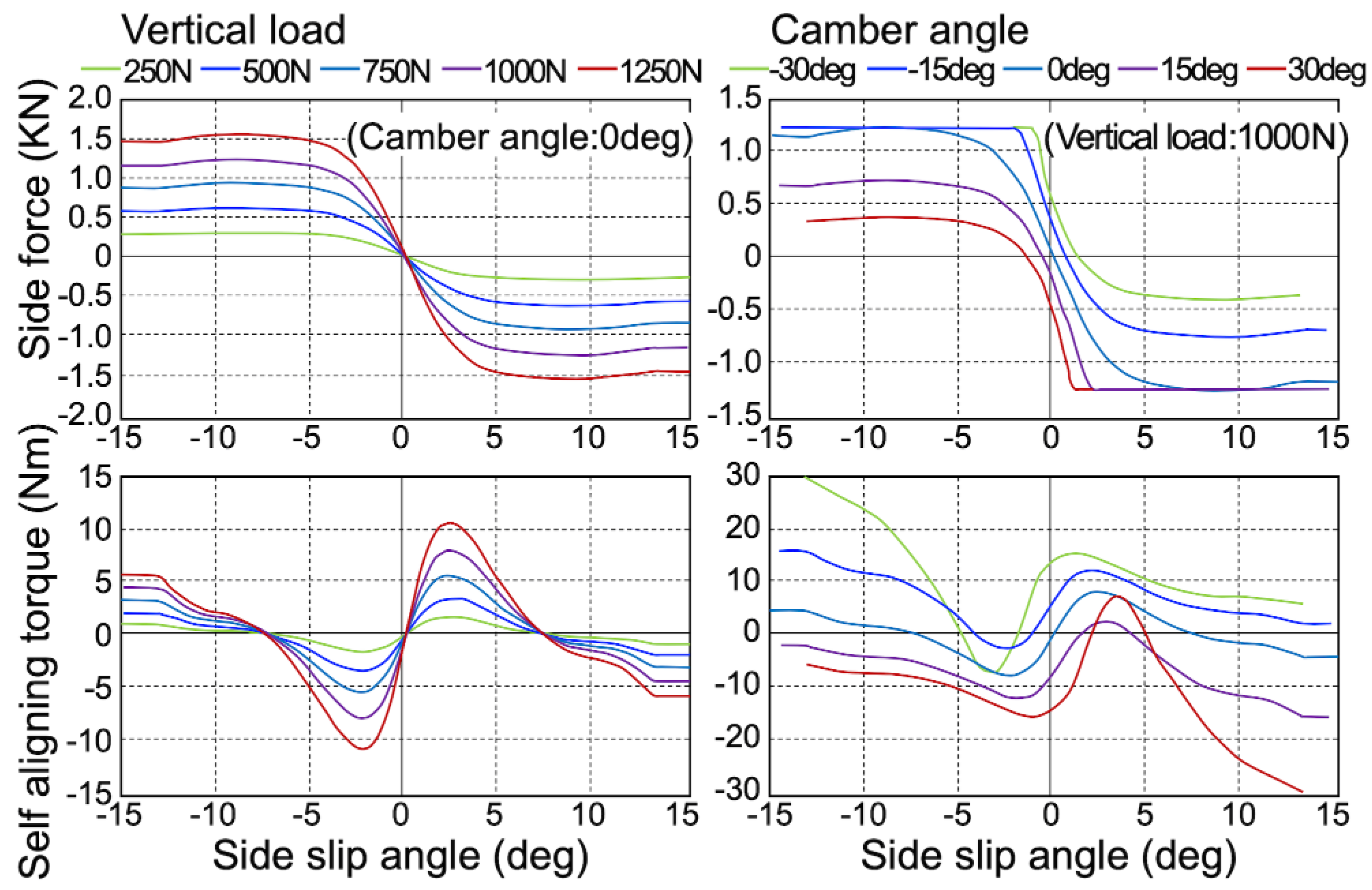
Figure 5.
PMV with two front wheels and one rear wheel.
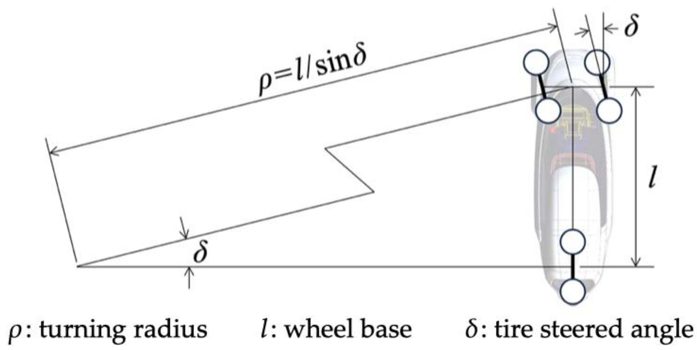
Figure 6.
PID tracking control [11].
Figure 6.
PID tracking control [11].
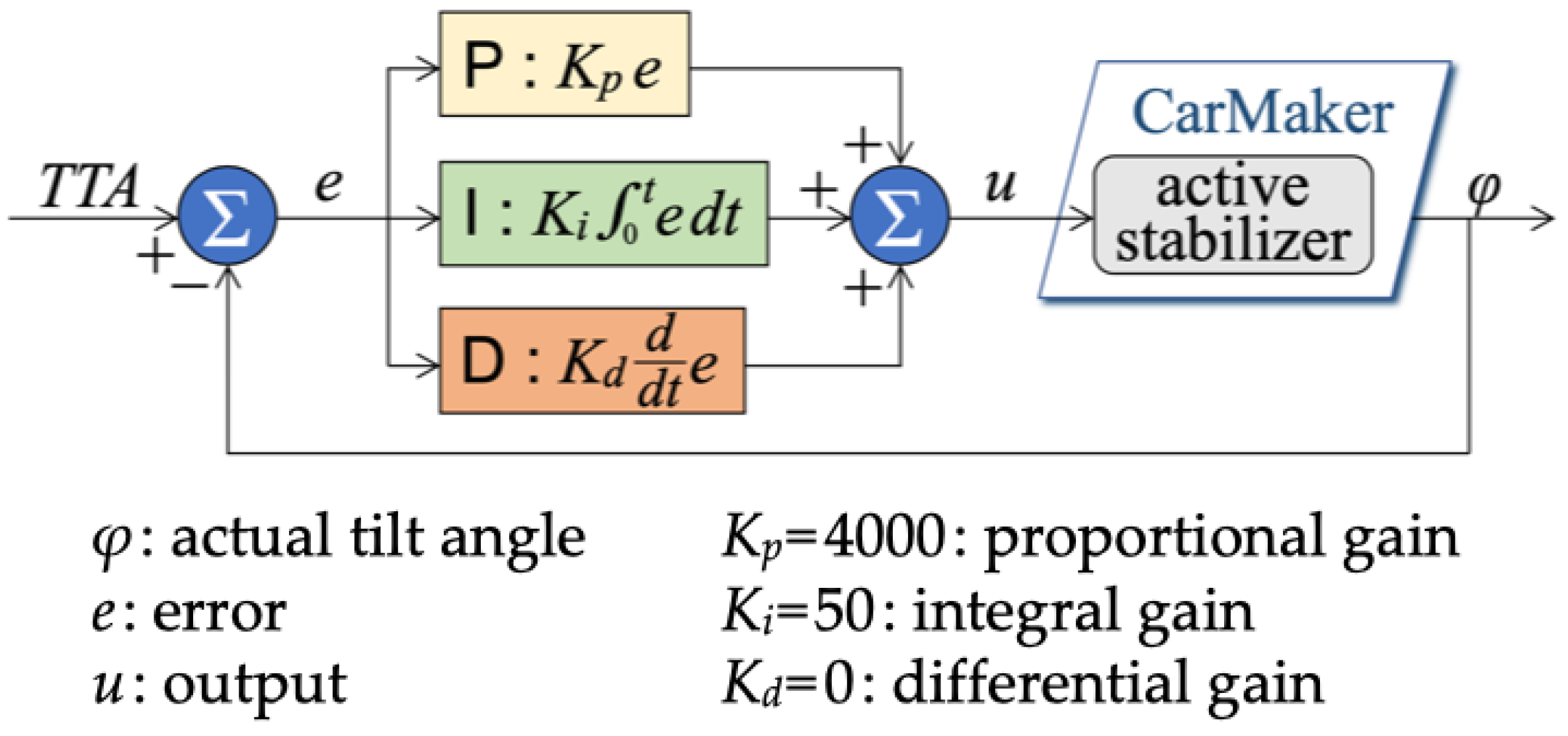
Figure 7.
Simulated Obstacle Avoidance Course.
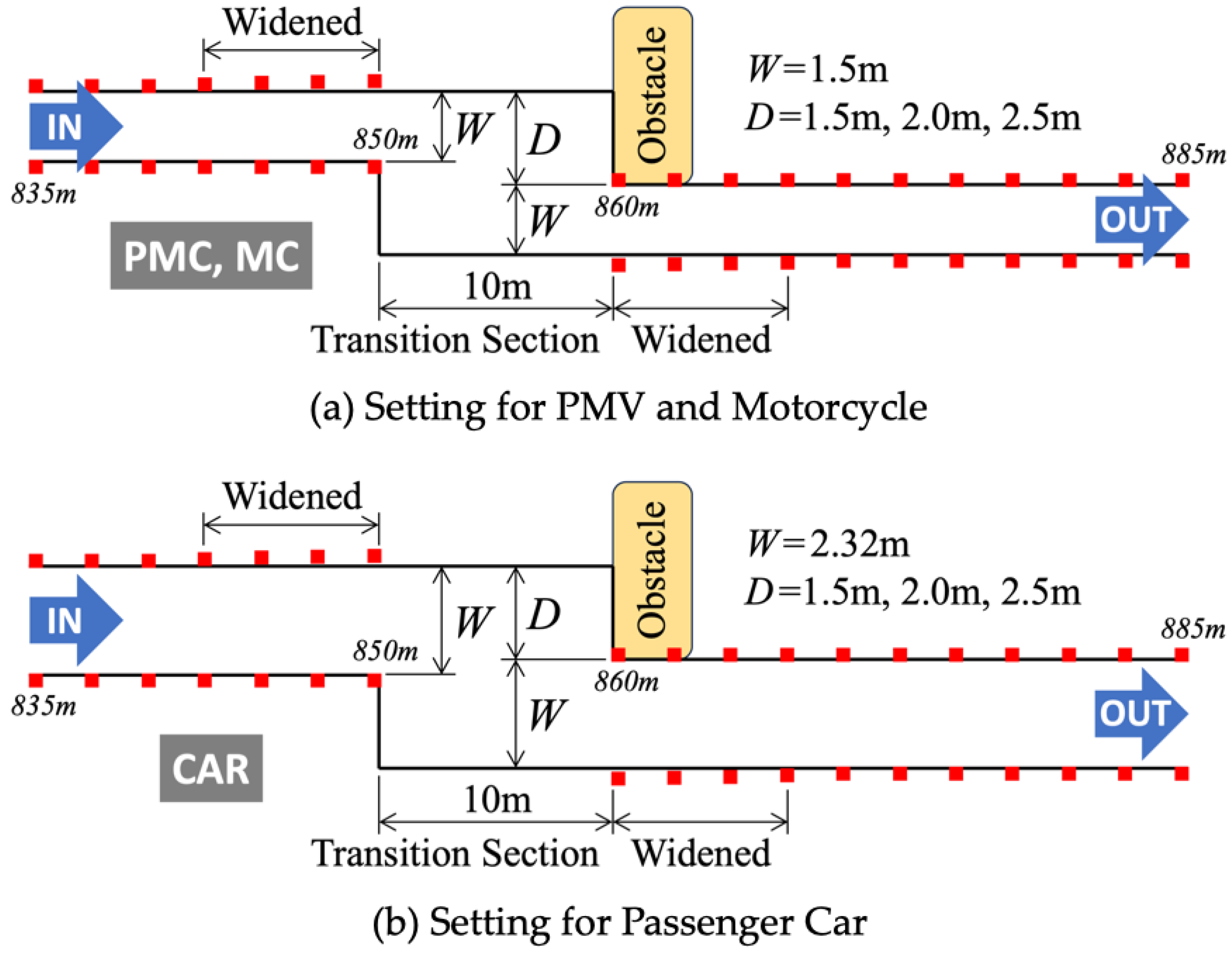
Figure 8.
Comparison of maximum passable speeds [8].
Figure 8.
Comparison of maximum passable speeds [8].
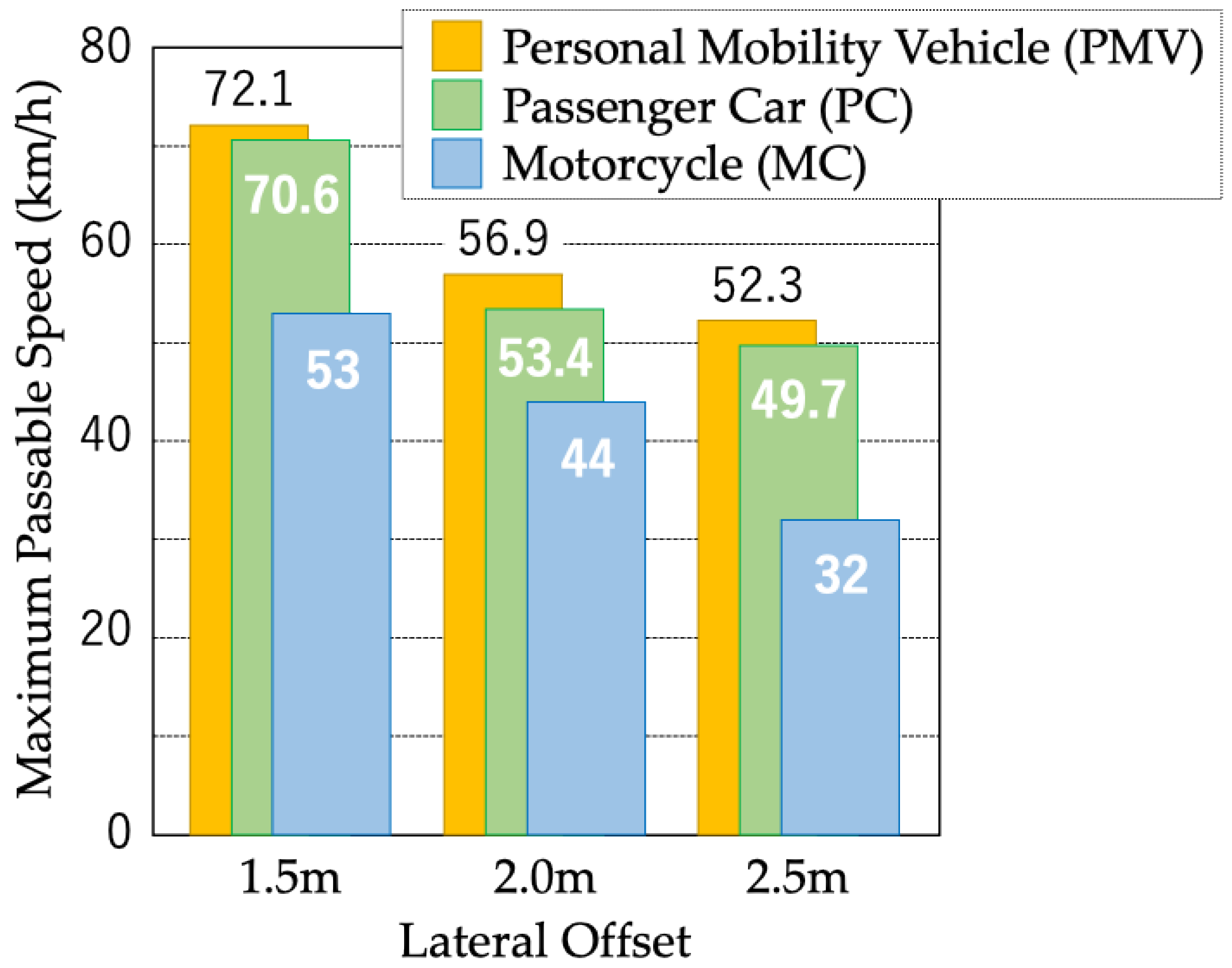
Figure 9.
Load transfer during turning in passenger cars.
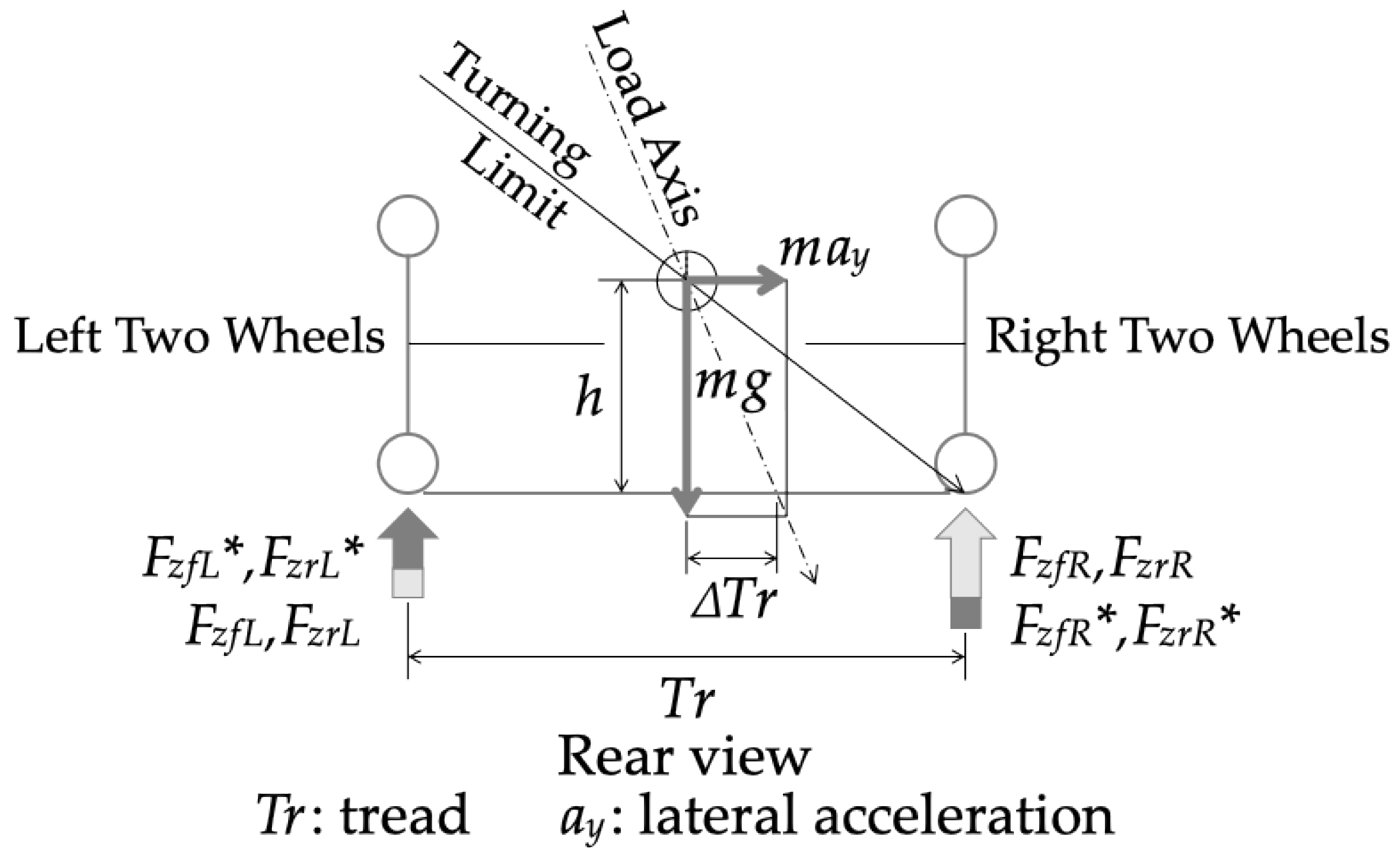
Figure 10.
Load transfer during turning in PMV.
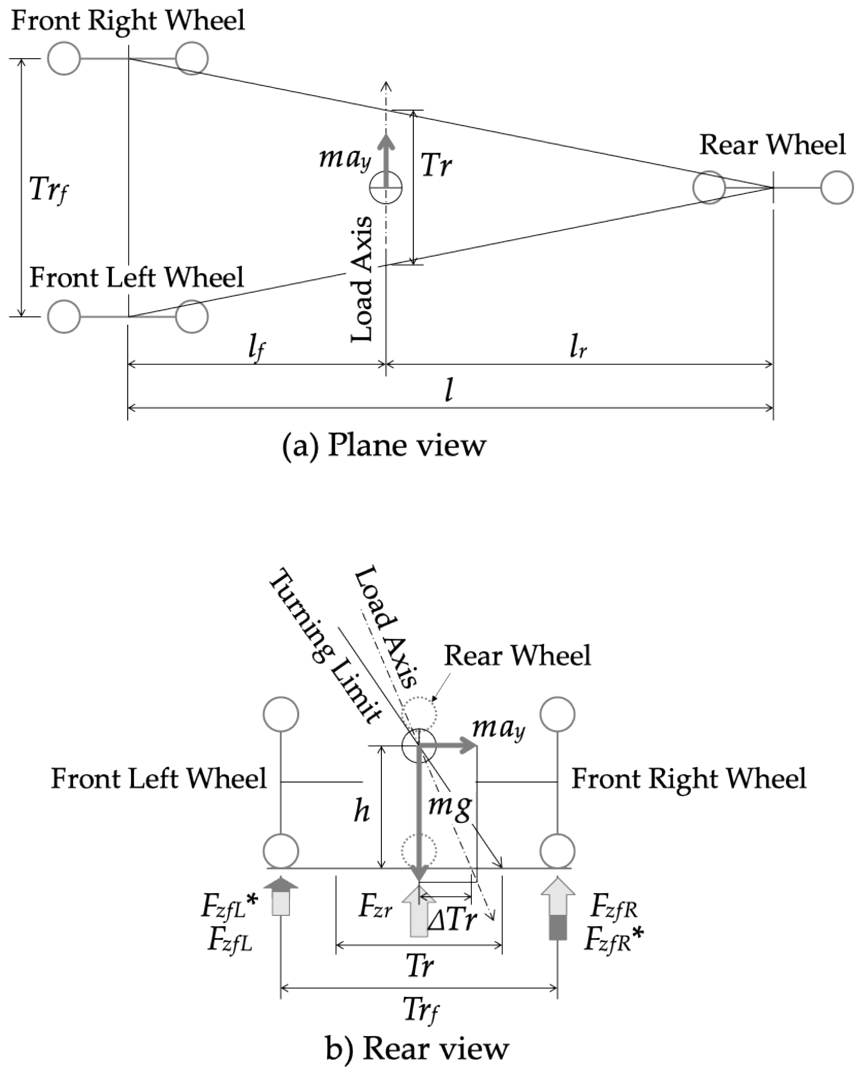
Figure 11.
No load transfer between front wheels while turning in PMV with inward tilting.
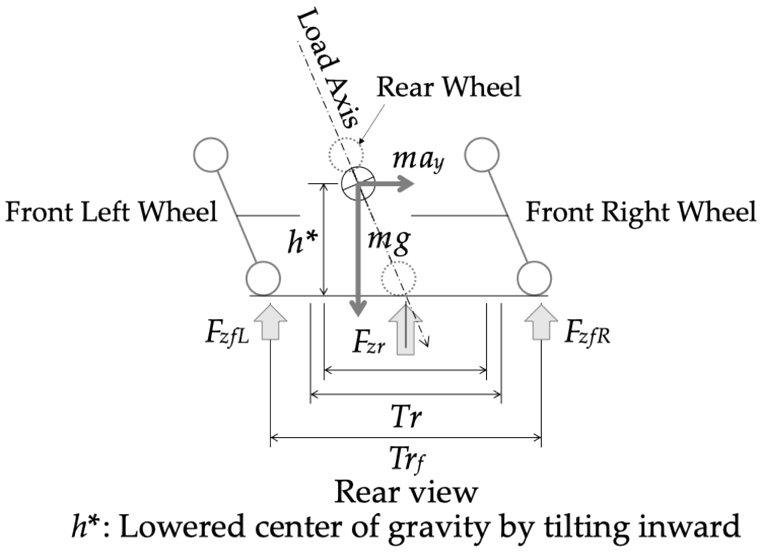
Figure 12.
Vehicle state of passenger car.
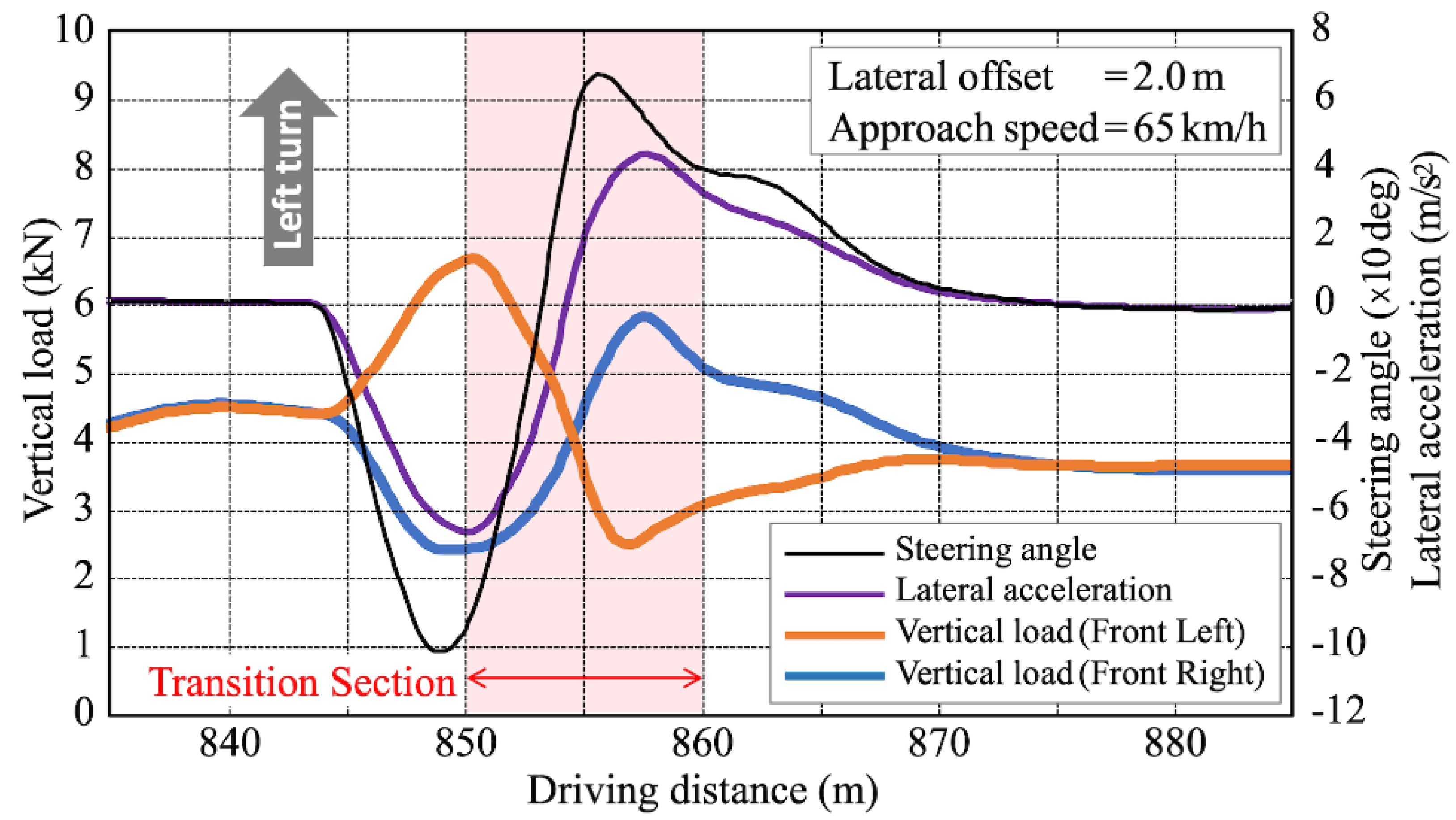
Figure 13.
Roll moment balance of car on the equivariant tilt [8].
Figure 13.
Roll moment balance of car on the equivariant tilt [8].
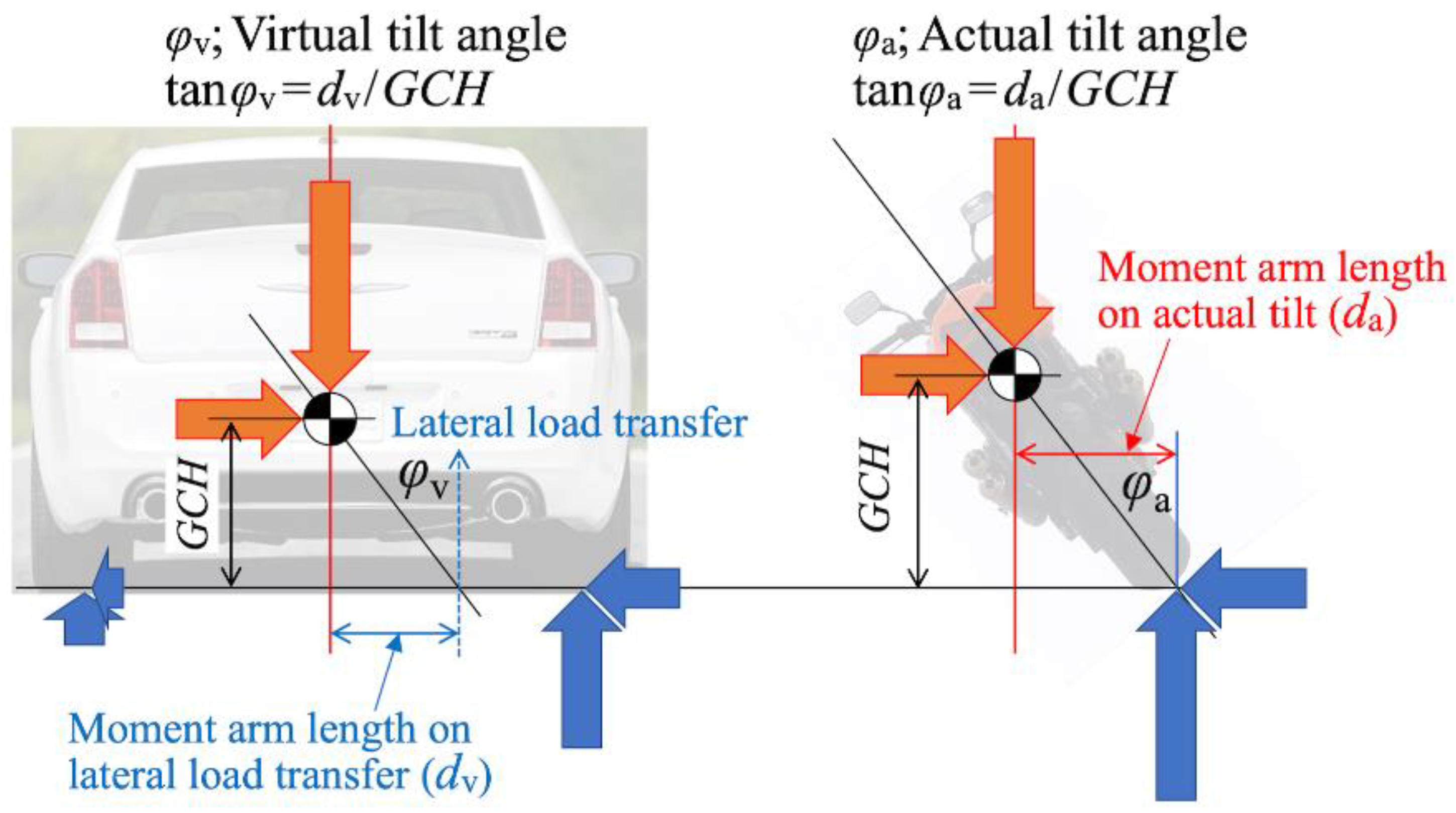
Figure 14.
PMV with two front wheels and one rear wheel.
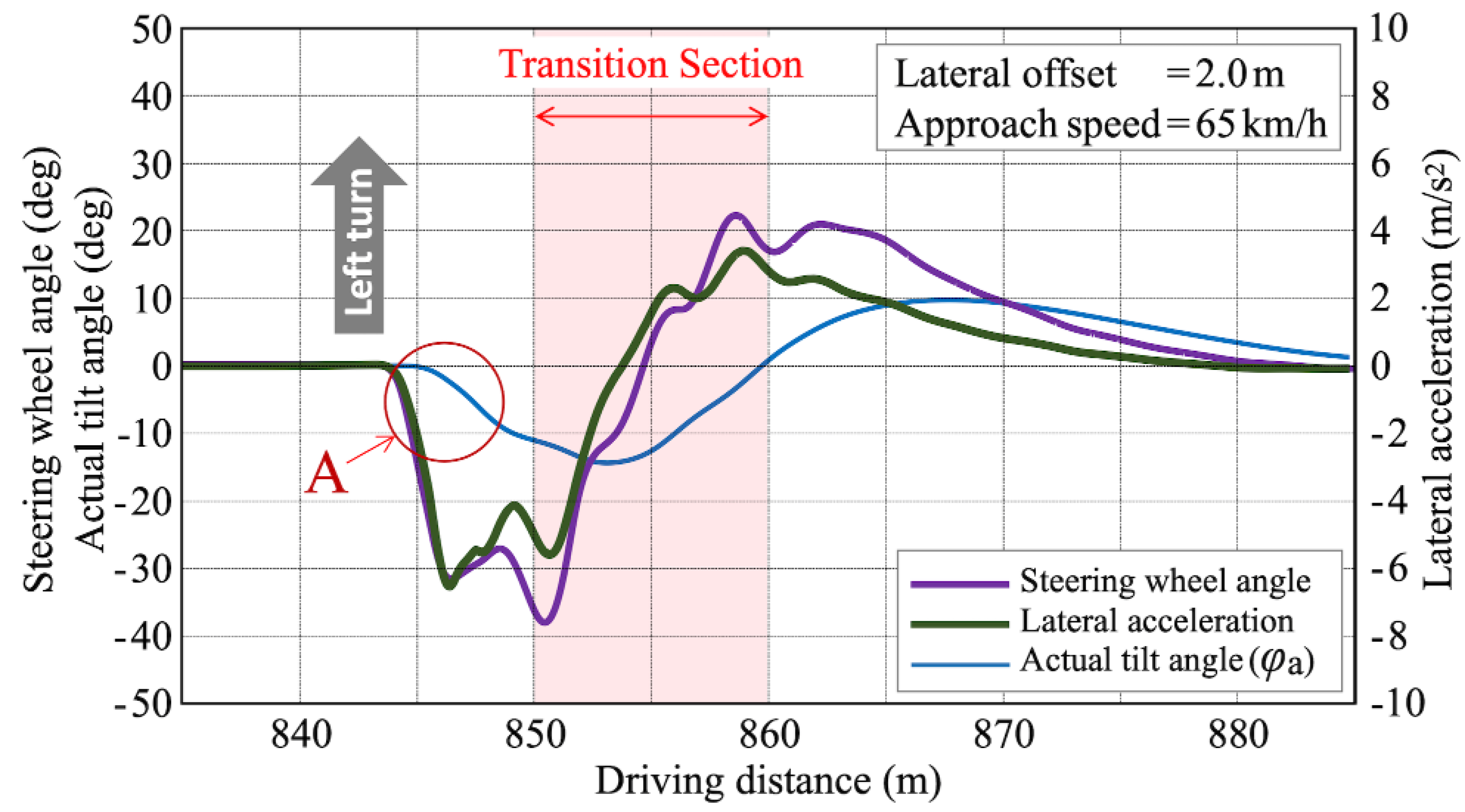
Figure 15.
PMV with two front wheels and one rear wheel.
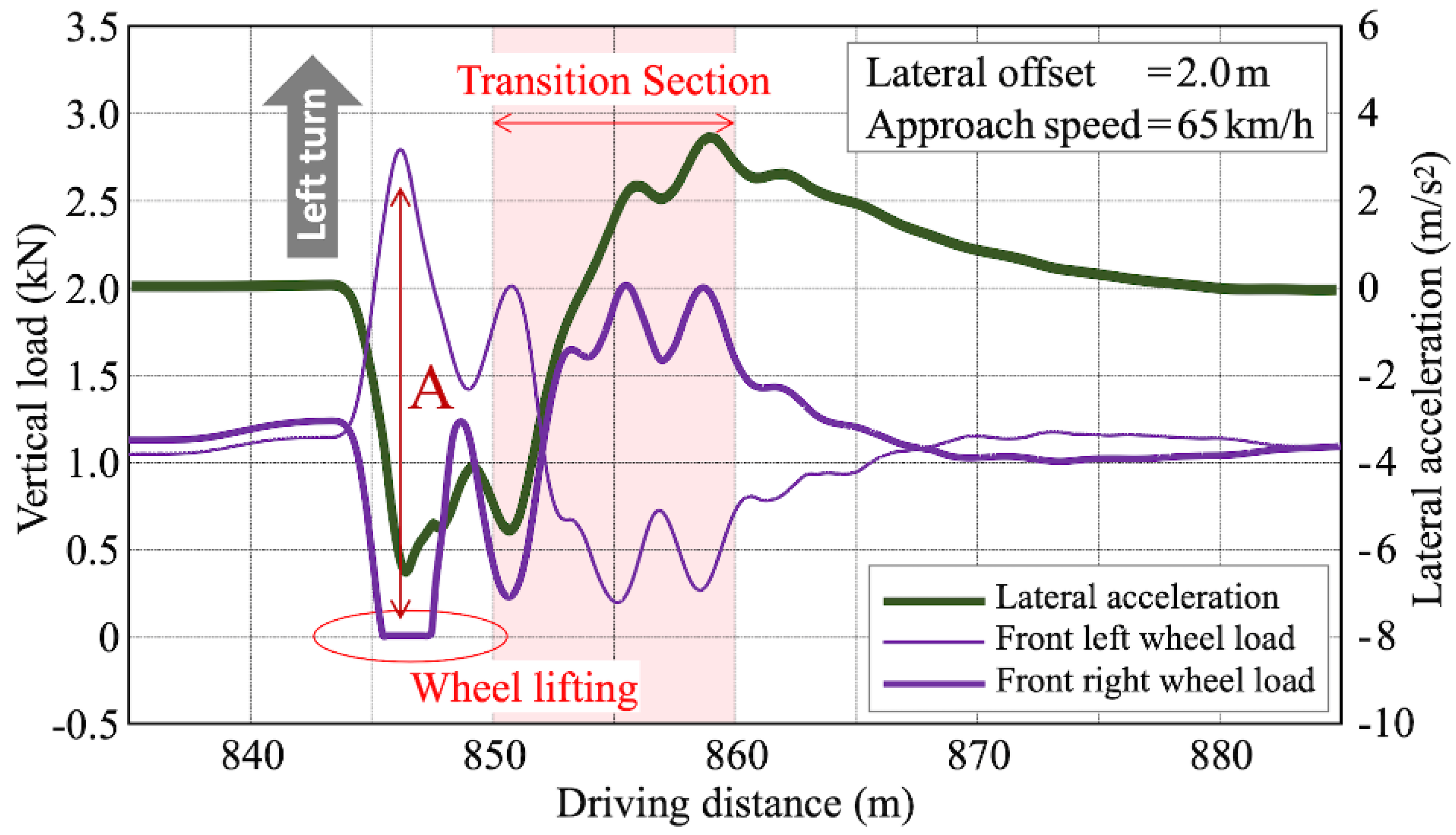
Figure 16.
Roll moment balance of PMV on the equivariant tilt [8].
Figure 16.
Roll moment balance of PMV on the equivariant tilt [8].
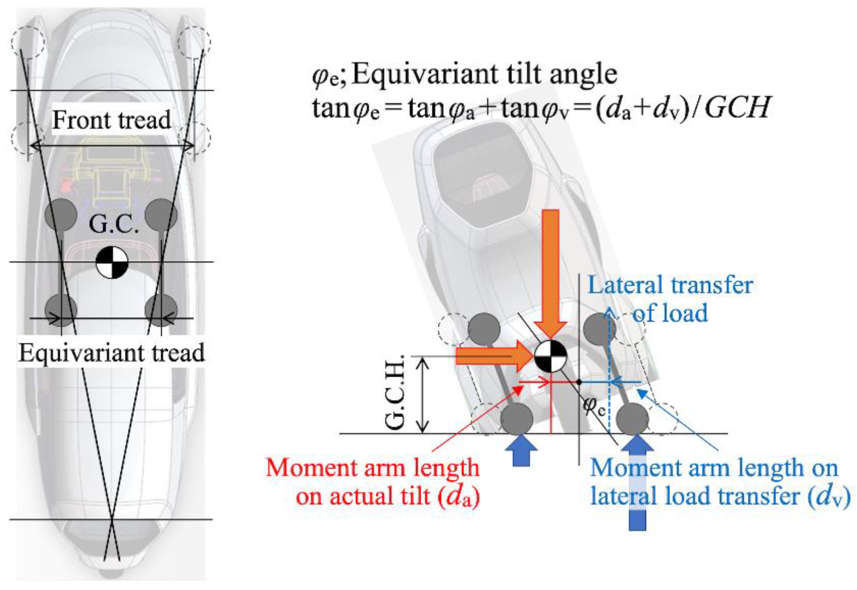
Figure 17.
Roll moment balance of PMV on the equivariant tilt.

| Item | Unit | Value | Item | Unit | Value |
|---|---|---|---|---|---|
| Total length | m | 2.645 | Front mass distribution | kg | 222 |
| Total width | m | 0.880 | Rear mass distribution | kg | 148 |
| Total height | m | 1.445 | Total mass | kg | 370 |
| Gravity center height | m | 0.358 | Roll inertia moment | Kgm2 | 58.8 |
| Wheel base | m | 2.020 | (Sprung inertia moment) | Kgm2 | 43.0 |
| Front distance from GC | m | 0.807 | Pitch inertia moment | Kgm2 | 197.3 |
| Rear distance from GC | m | 1.213 | (Sprung inertia moment) | Kgm2 | 118.0 |
| Front tread | m | 0.850 | Yaw inertia moment | Kgm2 | 187.3 |
| Steering Gear Ratio | - | 16.0 | (Sprung inertia moment) | Kgm2 | 102.3 |
Table 2.
Suspension characteristics.
| Item | Unit | Front Wheel | Rear Wheel |
|---|---|---|---|
| Spring constant | N/m | 5686 | 8654 |
| Damping constant (Stretching/Compression) | Ns/m | 1544/815 | 1142/727 |
Table 3.
Driver parameter and Maneuver [8].
Table 3.
Driver parameter and Maneuver [8].
| Driver | Maneuver | |||
|---|---|---|---|---|
| Item | Unit | Value | Item | Model |
| Corner Cutting Coefficient | 0.1 | Longitudinal Dynamics | IPGDriver | |
| Max. Long. Acceleration | m/s2 | 3.0 | Lateral Dynamics < 841.5m | Follow Course |
| Max. Long. Deceleration | m/s2 | -4.0 | (D=1.5m) > 841.5m | IPGDriver |
| Max. Lat. Acceleration | m/s2 | 20 | Lateral Dynamics < 843m | Follow Course |
| PylonShiftFdCoef | 0.15 | (D=2.0m) > 843m | IPGDriver | |
| Lateral Dynamics < 844m | Follow Course | |||
| (D=2.5m) > 844m | IPGDriver | |||
Table 4.
Specifications of Passenger Car and Motorcycle.
| Passenger Car | Motorcycle | ||||
|---|---|---|---|---|---|
| Item | Unit | Value | Item | Unit | Value |
| Total length | m | 4.150 | Total length | m | 2.140 |
| Total width | m | 1.700 | Total width | m | 0.637 |
| Total height | m | 1.600 | Total height | m | 1.318 |
| Gravity center height | m | 0.580 | Gravity center height | m | 0.450 |
| Wheel base | m | 3.185 | Wheel base | m | 1.576 |
| Front tread | m | 1.508 | Front mass distribution | kg | 123 |
| Rear tread | m | 1.494 | Rear mass distribution | kg | 75 |
| Total mass | kg | 1463 | Total mass | kg | 198 |
Disclaimer/Publisher’s Note: The statements, opinions and data contained in all publications are solely those of the individual author(s) and contributor(s) and not of MDPI and/or the editor(s). MDPI and/or the editor(s) disclaim responsibility for any injury to people or property resulting from any ideas, methods, instructions or products referred to in the content. |
© 2025 by the authors. Licensee MDPI, Basel, Switzerland. This article is an open access article distributed under the terms and conditions of the Creative Commons Attribution (CC BY) license (http://creativecommons.org/licenses/by/4.0/).
Copyright: This open access article is published under a Creative Commons CC BY 4.0 license, which permit the free download, distribution, and reuse, provided that the author and preprint are cited in any reuse.


