
Submitted:
07 May 2025
Posted:
07 May 2025
You are already at the latest version
Abstract
This study employs molecular dynamics (MD) simulations to investigate the 1 mechanical response and fracture behavior of penta-graphene, a novel two-dimensional 2 carbon allotrope composed entirely of pentagonal rings with mixed sp2–sp3 hybridization 3 and pronounced mechanical anisotropy. Atomistic simulations are carried out to eval- 4 uate the impact of structural defects on mechanical performance and to elucidate crack 5 propagation mechanisms. The results reveal that void defects involving sp3-hybridized 6 carbon atoms cause a more significant degradation in mechanical strength compared to 7 those involving sp2 atoms. During fracture, local atomic rearrangements and bond re- 8 constructions lead to the formation of energetically favorable ring structures—such as 9 hexagons and octagons—at the crack tip, promoting enhanced energy dissipation and frac- 10 ture resistance. A central focus of this work is the evaluation of the critical stress intensity 11 factor (SIF) under mixed-mode (I/II) loading conditions. The simulations demonstrate 12 that the critical SIF is influenced by the loading phase angle, with pure mode I exhibiting a 13 higher SIF than pure mode II. Notably, penta-graphene shows a critical SIF significantly 14 higher than that of graphene, indicating exceptional fracture toughness that is rare among 15 ultra-thin two-dimensional materials. This enhanced toughness is primarily attributed to 16 penta-graphene’s capacity for substantial out-of-plane deformation prior to failure, which 17 redistributes stress near the crack tip, delays crack initiation, and increases energy absorp- 18 tion. Additionally, the study examines crack growth paths as a function of loading phase 19 angle, revealing that branching and kinking can occur even under pure mode I loading.
Keywords:
2D Material
; Molecular Dynamics
; Penta-graphene
1. Introduction
In recent years, carbon allotropes have become a cornerstone of modern materials science research due to their diverse structures and unique properties. These allotropes exhibit remarkable physical, chemical, and electronic characteristics, making them indispensable in various technological fields. Diamond, graphite, fullerenes, carbon nanotubes, and graphene have significantly influenced advancements in medicine, electronics, energy storage, and composite materials [1,2,3,4].
Among these materials, graphene, a two-dimensional carbon allotrope, has garnered extensive attention due to its exceptional properties, including superior mechanical strength [5,6], excellent electrical conductivity [7,8], and outstanding thermal conductivity [9,10]. These properties have enabled graphene to revolutionize applications in nanoelectronics, flexible electronics, energy storage devices, and high-performance composites. However, despite these advantages, graphene has inherent limitations that restrict its widespread implementation in certain fields. One of the primary drawbacks is its lack of an intrinsic bandgap, which hinders its direct application in semiconductor technologies without additional modifications [11,12]. Additionally, challenges related to large-scale production and consistent quality [13,14], along with its sensitivity to chemical degradation under specific conditions [15,16,17], have led researchers to explore alternative two-dimensional materials with improved or complementary properties [18,19,20,21].
One such promising material is penta-graphene, a theoretically proposed two-dimensional carbon allotrope composed entirely of pentagonal rings [22]. Unlike graphene, penta-graphene possesses a natural bandgap [22,23,24], making it highly suitable for semiconductor and nanoelectronic applications. Furthermore, penta-graphene retains excellent thermal properties [25,26,27] and exhibits remarkable structural robustness [28,29,30], making it an attractive candidate for next-generation electronic and optoelectronic devices. Its potential applications extend beyond electronics, as its unique structure offers promising implications in energy storage, sensor technologies, and mechanical reinforcement in composite materials.
The atomic configuration of penta-graphene, illustrated in Figure 1, showcases a unique hybridization of and carbon atoms, structured into three distinct layers—top, middle, and bottom. The outer layers consist solely of hybridized atoms, while the middle layer contains hybridized atoms, providing structural stability and tunability through processes such as hydrogenation—a feature not present in graphene [23,31,32,33]. This adaptability through external stimuli like strain engineering and chemical functionalization augments its potential for integration into tunable electronic devices and quantum materials research. Furthermore, penta-graphene demonstrates enhanced chemical reactivity relative to graphene, primarily due to the inherent strain within its pentagonal rings. This reactivity aids in functionalization and chemical modifications, expanding its applicability across various fields including nanoelectronics, energy solutions, and composite material development.
In addition to its electronic versatility, penta-graphene exhibits remarkable mechanical characteristics. Penta-graphene also exhibits intrinsic mechanical anisotropy due to its pentagonal symmetry and mixed hybridization. The interplay between and bonding results in an optimal balance of rigidity and flexibility, leading to distinctive mechanical characteristics [34,35,36,37,38,39]. These properties suggest that penta-graphene could serve as a reinforcement material in high-performance composites, aerospace applications, and protective coatings. One of penta-graphene’s most unique mechanical properties is its negative Poisson’s ratio [37,40], which means that under tensile strain, it expands laterally instead of contracting. This counterintuitive behavior, often referred to as auxetic behavior, arises from the flattening of its layered structure under applied strain [41]. Such behavior is advantageous for applications requiring enhanced mechanical stability and energy dissipation, including impact-resistant materials and biomedical scaffolds.
Despite its theoretical promise, penta-graphene’s mechanical and fracture properties remain poorly understood. Experimental validation is currently unfeasible due to the lack of successful synthesis methods, though theoretical studies predict penta-graphene to be metastable [22]. In the absence of experimental data, molecular dynamics (MD) simulations serve as a critical tool for investigating penta-graphene’s mechanical behavior at the atomic scale [34]. By leveraging computational approaches, researchers can explore the deformation mechanisms, failure modes, and mechanical responses of penta-graphene under various loading conditions.
This study employs MD simulations to examine the mechanical and fracture response of monolayer penta-graphene under different loading conditions. Specifically, we analyze the effects of load angles, crack defects, and point defects on the material’s failure mechanisms. Additionally, we use MD simulations to determine the critical stress intensity factor for penta-graphene under mixed mode I and mode II loading.
2. Atomic Structure of Penta-Graphene
Penta-graphene features a distinctive pentagonal lattice structure, diverging from the hexagonal symmetry characteristic of conventional graphene. This arrangement, based on the Cairo pentagonal tiling, forms a periodically repeating network of pentagons, as illustrated in Figure 1. The unique structural motif is expected to have a profound impact on the material’s mechanical, electronic, and chemical properties.
The atomic structure of penta-graphene, presented in both top-down and side-view projections in Figure 1, reveals a mixed hybridization state of carbon atoms. The material consists of both - and -hybridized carbon atoms, arranged in a three-layered configuration. The side-view projection highlights this structure, showing a central layer of -hybridized carbon atoms (red) intercalated between two layers of -hybridized carbon atoms (blue and gray). The vertical displacement of -hybridized atoms relative to the layers results in an out-of-plane thickness of 1.2 Å.
Within this framework, the -hybridized atoms form planar bonds within the pentagonal rings, whereas the -hybridized atoms establish out-of-plane bonds. This layered configuration alleviates strain associated with non-hexagonal bonding, thereby enhancing structural stability. The combination of intrinsic stability, unique bonding characteristics, and three-dimensional layering imparts penta-graphene with both high stiffness and mechanical flexibility, making it a promising candidate for advanced structural and mechanical applications.
The unit cell, highlighted by a black square in Figure 1, features a lattice parameter of 3.64 Å, corresponding to the lengths of the unit vectors and , which define the dimensions along the X and Y axes, respectively. The unit cell contains six carbon atoms. The atomic composition maintains an : ratio of 1:2, with two and four carbon atoms per unit cell. This specific stoichiometry plays a crucial role in determining the material’s behavior. The bond lengths, measuring 1.55 Å for – bonds and 1.34 Å for – bonds, reflect the distinct bonding environments within the lattice. The bond angle between –– is 134.2 °.
A summary of key structural and bonding parameters is provided in Table 1. Future research should focus on the synthesis and characterization of penta-graphene to validate these theoretical predictions and explore its potential applications.
3. Methods
To investigate the behavior of penta-graphene, tensile tests are conducted using the MD simulation package LAMMPS (Large-scale Atomic/Molecular Massively Parallel Simulator) [42,43].
When selecting an empirical potential to model the interactions between carbon atoms in penta-graphene, Tersoff potentials are commonly utilized due to their capability to accurately simulate the complex interactions that are crucial for capturing the dynamic behavior of carbon-based materials under various stress conditions. Among various studies, it has been established that the Tersoff potential developed by Erhart and Albe in 2005 offers a suitable depiction of the mechanical and structural behaviors of penta-graphene [44]. This potential considers both the bond angle and the distance between atoms, which are vital for predicting the material’s behavior under tension, compression, and bending. The Tersoff potential models these interactions by considering the electronic environment of each atom, thereby allowing it to simulate how the material behaves under tension, compression, and bending. This is vital for accurately predicting fracture mechanics, as the potential can adapt to the changes in atomic configurations that occur near crack tips and other stress concentrators.
Specifically, the research by Winczewski et al. evaluated 14 different empirical potentials, including three Tersoff-type, two Stillinger-Weber-type, three REBO models, and three parameterizations of the REAX force field [45]. This comprehensive study highlighted that only the Tersoff-type potential by Erhart and Albe accurately reflects the characteristics of penta-graphene when compared to ab initio data, primarily because the potential’s parameters are derived from quantum mechanical calculations, ensuring that they are grounded in the fundamental physics of atomic interactions. Furthermore, the Tersoff potential has proven effective not only in modeling mechanical properties but also in calculating the stress intensity factor for various two-dimensional materials [46,47,48]. Due to its reliability in capturing mechanical and fracture behavior of carbon-based materials, we have employed the 2005 Erhart and Albe Tersoff potential for our simulations [44].
The simulation consists of two major stages: an equilibration stage and a deformation stage, each involving several specific steps to ensure an accurate representation of the system’s behavior. The equilibration stage begins with a minimization step to relax the system and eliminate any unfavorable interactions or strains. Following this, a constant pressure and temperature ensemble (NPT) is applied to the system for 10 picoseconds, with the temperature set at 1 Kelvin and the pressure set at 1 bar. This initial NPT phase allows the system to reach an equilibrium state under controlled pressure and temperature conditions. Subsequently, the temperature is gradually increased from 1 Kelvin to 300 Kelvin over 25 picoseconds, ensuring a smooth transition to the desired simulation temperature. The system is then held in an NPT ensemble for an additional 25 picoseconds to allow for further equilibration, during which the pressure and temperature are maintained constant. To stabilize the system, it is transferred to an NVE (constant number of atoms, volume, and energy) ensemble, where it is allowed to evolve for an additional 10 picoseconds, enabling any remaining fluctuations to dissipate.
In the deformation stage, the structure is subjected to tension under an NPT deformation. An engineering strain rate of 0.001ps−1 is applied, causing the structure to deform and expand gradually. The deformation process is carried out for a total of 1000 picoseconds, during which the structure’s width is doubled relative to its original dimensions. The simulation may be stopped early upon reaching the point of total structural failure to save system resources. Data from the deformation stage is used to investigate the structure’s response to applied strain, providing insights into its mechanical properties.
Stress-strain curves can be obtained from this process by recording the stress in the material during loading. The modulus of elasticity can then be calculated from the initial linear elastic region of the stress-strain curve. The initial slope of this curve over the strain range from 0 to 0.1 is used to determine the modulus of elasticity, and the highest stress is used to determine the fracture strength of the material.
4. Impact of Defects on Mechanical Properties of Penta-Graphene
The mechanical properties of penta-graphene, like those of other two-dimensional materials, are highly sensitive to structural imperfections [49,50,51]. Among these, point defects such as vacancies and initial cracks play a particularly critical role. These localized disruptions can significantly reduce the material’s tensile strength, elasticity, and fracture toughness, despite the inherent robustness of its pentagonal lattice structure. Given that such defects are inevitable during synthesis, processing, and operational use, understanding their impact is crucial for both fundamental research and practical applications.
Voids, or atomic vacancies, are an inherent aspect of real materials, arising from imperfections during synthesis, fabrication, or operational wear. These missing atoms disrupt the local bonding environment, creating stress concentrations around defect sites and impairing the material’s ability to distribute mechanical loads uniformly. Such irregularities weaken the structural integrity of penta-graphene, reducing its load-bearing capacity and altering its mechanical response. The distribution and density of voids further influence the material’s elasticity and fracture resistance, making their characterization essential for predicting mechanical performance.
Similarly, initial cracks—whether microscopic or larger in scale—serve as critical stress concentrators, significantly affecting mechanical behavior. These preexisting flaws act as nucleation sites for crack propagation under applied loading, accelerating structural failure. Unlike vacancies, which primarily disrupt localized stress distribution, cracks compromise the overall integrity of the material by facilitating mechanical energy accumulation and fracture progression. The combined presence of voids and cracks exacerbates structural weaknesses, necessitating a comprehensive understanding of their impact for material optimization.
In this study, we investigate the influence of these defects on the stress-strain behavior, elastic modulus, and strength of penta-graphene. A series of simulations are conducted to systematically examine the effects of void percentage and distribution on mechanical properties. Additionally, we analyze how varying crack size and orientation impact the material’s response under mechanical loading.
4.1. Impact of Point Defects on the Mechanical Properties
In penta-graphene, the coexistence of and hybridized carbon atoms creates a complex and mechanically robust structure that combines planar and out-of-plane bonding characteristics. However, the introduction of point defects—such as vacancies, substitutions, and interstitial atoms—can disrupt this delicate balance and significantly alter the material’s mechanical behavior. It is essential to study point defects associated with both and hybridized carbon atoms because their effects on the mechanical integrity of penta-graphene differ due to the nature of their bonding.
Defects in -hybridized regions primarily impact the planar bonding network, which can lead to reduced flexibility and increased brittleness. Since bonds are generally stronger but less flexible than bonds, a defect in this region could localize stress and act as a nucleation point for crack initiation and propagation. Conversely, defects in -hybridized regions may introduce distortions in the three-dimensional stacking and interlayer interactions, potentially affecting the out-of-plane rigidity and load transfer mechanisms that contribute to penta-graphene’s mechanical resilience. These disruptions can alter how the material accommodates deformation, impacting its ability to distribute stress uniformly and leading to localized structural instabilities that may compromise its overall mechanical performance.
To thoroughly evaluate the impact of point defects in penta-graphene, void defects are independently introduced into both the and hybridized carbon atoms. Defect densities are systematically varied from 0% to 20% in increments of 5% for each carbon type. This approach results in a total of 25 unique simulations that explore various possible combinations of defect densities. For these simulations, a square sheet of side length 215.95Å is used, totaling 21,721 atoms. This provides a large enough sample of atoms to examine how void defects affect the mechanical properties of penta-graphene on average. By analyzing these scenarios, the study aims to assess the relative importance of defects in the and regions and provide insights into how they affect the mechanical resilience of penta-graphene.
Figure 2 presents select stress-strain curves from void defect simulations of the penta-graphene sheet, demonstrating the impact of varying and carbon defect concentrations. The results reveal that as the void defect density increases, the ultimate stress before fracture decreases. However, beyond a certain defect threshold, the material exhibits greater strain before failure, indicating enhanced ductility. When the proportion of defects exceeds this critical threshold, the material becomes even more flexible, delaying fracture to higher strain values while simultaneously reducing its maximum load-bearing capacity.
This behavior can be attributed to the distinct mechanical roles of and hybridized carbon atoms in penta-graphene. Initially, as void defects increase, the removal of bonds reduces the structural integrity of the material, leading to a decrease in ultimate stress. This is because fewer intact bonds are available to sustain the applied load, resulting in earlier failure. However, beyond a critical defect density, localized flexibility emerges due to disruptions in the hybridized network, allowing for increased deformation before fracture. The presence of voids in regions weakens the material’s out-of-plane rigidity, making it more adaptable under strain. Consequently, the failure point shifts to higher strain values, but the weakened atomic framework results in a reduced maximum stress before failure. This balance between the rigidity provided by bonding and the planar strength maintained by bonding governs penta-graphene’s mechanical response to void defects.
The Young’s modulus and maximum strength of the penta-graphene sheets as a function of defect percentage are shown in Figure 3. The graph demonstrates that the elastic modulus steadily declines with increasing void defects. This figure also indicates that void defects in -hybridized carbon atoms have a more pronounced impact on reducing the material’s overall elasticity compared to defects in -hybridized regions. An increase in defects from a pristine sheet to 20% voids leads to a drop in elasticity of roughly 60 N/m, while a similar increase in void defects reduces the elasticity 70 N/m. If 20 % defects are already present, defects have a negligible effect on the overall stiffness of the material. This suggests that the integrity of the central plane of -bonded atoms play a critical role in maintaining the material’s stiffness. The exterior atoms also contribute to the stiffness of the structure, but require a higher defect percent to produce the same effect.
In contrast, the fracture strength data reveal that the difference in the impact of increasing versus defects is less pronounced. A reduction in the concentration of either carbon type is equally likely to disrupt these critical – bonds, leading to structural failure. This underscores the importance of the – bonds as key contributors to the mechanical strength of penta-graphene. Maintaining the integrity of these mixed-hybridization bonds is crucial for preserving the material’s load-bearing capacity and resistance to fracture.
4.2. Impact of Initial Crack Size on the Mechanical Properties
Understanding the impact of pre-existing cracks on the mechanical properties of penta-graphene is crucial for evaluating its structural reliability and suitability for practical applications. Initial cracks can significantly influence the material’s mechanical strength and fracture behavior, making it essential to study their effects for accurate failure predictions. Gaining insights into crack-induced weaknesses is key to enhancing the durability and mechanical resilience of penta-graphene in advanced technologies such as flexible electronics, nanoelectromechanical systems (NEMS), and high-strength composite materials.
To examine the relationship between crack size and mechanical performance, a series of simulations were conducted with varying crack widths. The cracks introduced into the pristine material range from 30.59Å to 73.78Å in width, increasing in increments of 7.2Å. This increment, equivalent to two unit cells, was chosen to maintain a consistent microstructural configuration of the crack. The crack opening is set at 7.2Å to minimize artifacts arising from interactions between free crack edges. Figure 4 shows a penta-graphene sheet with an initial crack with a crack opening of 7.2Å. In simulations of crack defects, we use a simulation domain of 431.91 Å by 215.95 Å, including 43,123 atoms. The longer dimension is aligned with the direction of the crack edge to help mitigate edge effects. This systematic approach enables a comprehensive analysis of how initial crack sizes influence fracture behavior and mechanical stability.
Figure 5 presents the stress-strain curves for penta-graphene with different initial crack sizes, while Figure 6a and Figure 6b show the Young’s modulus and fracture strength respectively. As expected, an increase in initial crack size results in a notable reduction in both overall strength and stiffness. The stress-strain curves exhibit a characteristic linear elastic region, followed by failure at higher strain levels. This behavior is consistent with brittle fracture mechanics, where the material deforms elastically before experiencing catastrophic failure.
A key observation is the progressive decline in peak stress at failure and the overall stiffness as crack size increases, highlighting a weakened mechanical response. Larger cracks serve as stress concentrators, amplifying localized stress and expediting fracture initiation. The reduction in stiffness arises from the disruption of the material’s bonding network, which diminishes its load-bearing capacity.
Interestingly, some simulations exhibited a multi-stage failure process, where the material does not fail catastrophically in a single event. This phenomenon is particularly evident for larger crack sizes, where an initial drop in stress is followed by partial structural recovery, allowing the material to endure higher strains before complete failure. This behavior can be attributed to the atomic restructuring that occurs during the initial fracture.
Penta-graphene’s rigid three-dimensional structure contributes significantly to this mechanical response. When oriented in the X–Y plane, many atomic bonds retain components in the Z-direction. Under tensile strain, these out-of-plane components undergo atomic de-wrinkling, progressively flattening the structure. However, due to its pentagonal tiling, which does not allow perfect tessellation in a two-dimensional plane, penta-graphene experiences internal compression. This compression increases transverse stress on the bonds, ultimately leading to bond rupture. If the initial fracture does not lead to immediate catastrophic failure, the material can adapt by restructuring its atomic configuration, forming carbon loops that contain 6 to 12 atoms, as noted in [41]. This restructuring process is depicted in Figure 7, where areas of atomic reconfiguration are highlighted in green.
The stress distribution and crack growth at different strain levels for a penta-graphene sheet with an initial crack length of Å are shown in Figure 8. As the crack propagates, larger loops of carbon atoms form behind the crack tip, keeping the top and bottom surfaces connected. This phenomenon helps increase the failure strain and prevents sudden failure after the initial maximum stress is reached. The ability of these atomic chains to redistribute stress enhances the structural integrity of penta-graphene, contributing to its overall fracture resistance.
This phenomenon is influenced by both applied stress and temperature. The formation of the larger carbon loops helps relieve localized stress, enabling the material to sustain higher strains after the initial fracture. Due to stress concentration around crack tips, these phase transitions frequently originate at the crack corners and propagate diagonally away from the crack site, redistributing stress throughout the structure. Such structural adaptability contributes to the material’s unique fracture behavior, making penta-graphene an intriguing candidate for applications requiring both high strength and flexibility.
4.3. Effect of Loading Direction on the Behavior of Penta-Graphene
The simulations of previous sections examined the mechanical behavior of penta–graphene sheets constructed using the unit cell depicted in Figure 1, under tensile loading along the direction. To understand the effects of loading direction on the mechanical properties of penta–graphene, we expanded our study to include uniaxial tensile tests on penta–graphene sheets oriented at various angles.
In this series of simulations, penta–graphene sheets were generated with orientations varying from 0° to 90°, using the unit cells illustrated in Figure 9. The dimensions of each unit cell for the respective orientations are listed in Table 2. To ensure uniformity across tests, the sheets are designed with a periodic structure in all directions, with dimensions of approximately 215.95 by 215.95 Å, mirroring the configurations used in the void defect simulations.
The stress-strain curves for different orientations, are displayed in Figure 10. Due to the rotational symmetry of the penta-graphene unit cell, the material exhibits similar mechanical properties at both 0° and 90°. Figure 11 a and Figure 11 b further delineate how the loading angle impacts the Young’s modulus and fracture strength of penta-graphene.
Analysis of the results reveals that the fracture strength is relatively invariant to changes in the loading orientation, yet the modulus of elasticity, derived from the linear portion of the stress-strain curves, demonstrates a noticeable dependence on the loading angle. The lowest elastic modulus occurs when the penta-graphene sheet is oriented at 45°, highlighting a directional anisotropy in mechanical stiffness. This trend is symmetric about the 45° angle, likely reflecting the 90° rotational symmetry characteristic of penta–graphene. In this orientation, the material shows a decreased resistance to deformation, necessitating a strain of about 0.02 before substantial load-bearing capacity is achieved, resulting in a shift of the entire stress-strain curve toward higher strain values. Contrary to the elasticity, the fracture strength does not display a consistent trend with the angle of rotation, remaining relatively stable around 30 N/m with a variation of ±5
Fracture initiation is consistently observed at the bonds between and carbon atoms. Initially, the rupture of a single bond combines two pentagonal () loops into an octagonal () loop, precipitating a brittle failure. This phenomenon is particularly evident in sheets oriented at 0°, as illustrated in Figure 7. The formation of loops redistributes stress to adjacent bonds, leading to a sequential rupture of bonds and the formation of additional loops, thereby exacerbating the propagation of the crack.
5. Surface Energy of Penta-Graphene
Surface energy () in penta-graphene quantifies the energy required to create new surfaces within the material. This is calculated by comparing the total energy of a pristine sheet () with that of the same sheet after introducing free surfaces (U), using the equation:
where l is the length of the sheet along the considered axis, and t is the thickness of the sheet. The factor of 2 accounts for the creation of two new surfaces.
In this study, we assume a penta-graphene thickness of 3.68 Å, as estimated from multilayer simulations with periodic boundary conditions in the thickness direction [52]. To determine , the penta-graphene sheet is simulated with periodic boundary conditions in both in-plane directions (X and Y), while keeping the Z-direction fixed. The total energy U is then obtained by modifying the boundary conditions to introduce a free surface along the desired fracture direction. Specifically, for surfaces oriented along the -direction (normal to the Y-direction), periodicity is maintained in the Y direction, with the X and Z directions fixed. Similarly, for surfaces oriented along the -direction (normal to the X-direction), periodicity is maintained in the X direction, with the Y and Z directions fixed. By substituting these computed energy values into Equation 1, the surface energies of penta-graphene along the and directions are found to be 4.434 J/m2 and 6.771 J/m2, respectively. These values are lower than the surface energy of graphene, which is about 8 J/m2 [53].
6. Molecular Dynamics Simulations for Mixed-Mode Fracture in Penta-Graphene
The critical stress intensity factor is a fundamental parameter in fracture mechanics that quantifies a material’s resistance to crack propagation under applied stress [56]. For emerging nanomaterials like penta-graphene, understanding the critical stress intensity factor is crucial for evaluating their mechanical reliability and fracture toughness, particularly in the presence of defects such as pre-existing cracks or voids.
Studying the critical stress intensity factor of penta-graphene offers insights into how the material manages localized stress, particularly near defects. An understanding of critical stress intensity factor is crucial for predicting whether a crack will remain stable or grow uncontrollably, which is vital for preventing catastrophic failure in real-world applications. Additionally, exploring how the critical stress intensity factor is affected by factors such as crack geometry and loading conditions can guide the development of more defect-tolerant penta-graphene based materials.
This section presents MD simulations aimed at analyzing the critical stress intensity factor and crack propagation path of penta-graphene under mixed-mode loading. A circular domain surrounding the crack tip is employed for the analysis. The MD simulations apply asymptotic crack-tip displacement fields to the outermost atomic layers, as illustrated in Figure 12.
The far-field behavior is assumed to be linear and isotropic due to the rapid decay of the crack-tip strain field, whereas the anisotropic nature of penta-graphene becomes significant only under large strain conditions. The asymptotic displacement fields at the crack tip for a linear isotropic material under mixed-mode I and II fracture are given by equations 2 and 3 [50,57]:
Here, and represent displacements in the x- and y-directions, respectively. The parameter E denotes the elastic modulus, and is Poisson’s ratio. The variable r is the radius of the circular domain, while is the angle in polar coordinates. The Kolosov constant is given by for plane stress. The terms and denote the mode I (tensile) and mode II (in-plane shear) stress intensity factors, respectively.
For mixed-mode loading, the effective stress intensity factor is determined as
The loading phase angle is given by
where corresponds to pure mode II (shear) loading and corresponds to pure mode I (tensile) loading. Based on our MD simulations, the Young’s modulus for penta-graphene is taken as GPa, and Poisson’s ratio is [45]. To examine the effect of crack edge structure and crack-tip configuration on the critical stress intensity factor, two distinct crack configurations (configurations A and B) are analyzed, as illustrated in Figure 13. Both configurations share identical lengths and widths to ensure a valid comparison.
The boundary conditions are applied incrementally with . Time integration is performed using the velocity-Verlet algorithm with a time step of 1 femtosecond (fs). Simulations are conducted at a temperature of 300 K. Following each loading increment, the boundary atoms are fixed while the internal atoms are relaxed for 60,000 time steps, corresponding to a strain rate of .
As MD simulation results can be sensitive to loading rates and due to the lack of experimental data on the fracture properties of penta-graphene, this study primarily provides qualitative insights into fracture behavior and trends. However, additional MD simulations with an extended relaxation period of 500,000 time steps were conducted, showing no qualitative differences in the reported results.
Due to the asymmetry at the crack tip and along the crack edges, simulations are performed for phase angles ranging from to . The boundary conditions are periodic in the X, Y, and Z directions, and the Tersoff potential is used for the simulations, which are conducted at 500K.
The crack propagation paths for configurations A and B are presented in Figure 14. These figures demonstrate that, despite differences in crack tip geometry, the cracks in both configurations propagate in the same direction when subjected to identical loading phase angles. This indicates that the loading phase angle is a critical factor in determining the crack propagation direction. At a loading phase angle (pure mode I), the crack propagation in a self similar path while for all the other phase angles, the crack propagates by kinking. For positive loading phase angles, the crack propagates downward, whereas, for negative loading phase angles, it propagates upward.
A notable observation is that under mixed-mode loading, the penta-graphene sheet experiences out-of-plane deformation. The out-of-plane deformations of the sheet under pure mode I and mode II loading are illustrated in Figure 16. Similar deformations have also been reported in other two-dimensional materials [58,59]. These deformations contribute to the absorption of external energy, delaying crack propagation and thereby increasing the critical stress intensity factor.
Figure 15 illustrates the variation of the critical stress intensity factor as a function of the loading phase angle for configurations A and B. Both configurations exhibit nearly identical values of at specific loading phase angles, suggesting that differences in the crack tip or crack edge have no significant influence on the effective stress intensity factor. Furthermore, the graph demonstrates symmetry for both positive and negative phase angles.
Figure 15.
Effective critical stress intensity as a function of loading phase angle (configuration A and B)
Figure 15.
Effective critical stress intensity as a function of loading phase angle (configuration A and B)
Figure 16.
The out-of-plane deformation of penta-graphene sheet a) pure mode I, b) pure mode II
From these plots, the critical stress intensity factor for pure mode I is determined to be , while for pure mode II, it is . The stress intensity factor for penta-graphene is higher than that of graphene. Experimental measurements indicate that the mode I SIF for graphene is approximately [46,53], while molecular dynamics simulations report values ranging from to [55,60,61].
The elevated stress intensity factor (SIF) of penta-graphene, relative to graphene, can be primarily attributed to its unique atomic architecture and associated deformation mechanisms. While graphene features a flat hexagonal lattice composed exclusively of sp2-hybridized carbon atoms, penta-graphene adopts a buckled configuration formed by pentagonal carbon rings with a combination of sp2 and sp3 hybridization. This non-planar structure introduces the capacity for pronounced out-of-plane deformation, which is an intrinsic toughening mechanism. Despite possessing lower surface energy than graphene, penta-graphene’s ability to dissipate mechanical energy through structural flexibility enhances its resistance to crack initiation and propagation, resulting in a higher critical SIF.
The role of out-of-plane deformation is particularly significant in fracture processes. Under applied stress, penta-graphene can bend and locally rearrange its atomic structure, facilitating stress redistribution around crack tips. This energy is partially absorbed through mechanisms such as lattice distortion and in-plane stretching, thereby reducing the effective energy available for crack advancement. As a result, crack propagation is delayed, and the material exhibits greater toughness and a higher threshold for fracture.
This fracture behavior aligns with observations in other two-dimensional materials, such as and , where out-of-plane deformation has been shown to enhance toughness [54,62,63,64]. In our simulations, penta-graphene displayed similar deformation-driven toughening, supporting earlier findings on strain-induced energy dissipation mechanisms in 2D systems [65].
6.1. Stress Distribution
To analyze the stress distribution in a penta-graphene sheet, the stress tensor per atom is determined using the virial formulation. This method is commonly used in atomistic simulations to compute local stress fields by incorporating both kinetic and potential contributions to stress at the atomic scale. For an atom a, the virial stress is computed using the following expression [51,66,67,68].
In this equation, represents the stress tensor for atom a. The term denotes the atomic volume, while represents the atomic mass. The velocity components of atom in the and directions are given by and , respectively. The parameter n corresponds to the number of neighboring atoms within the interaction domain of atom a. The distance vector component between atoms a and b along the direction is denoted by , while represents the component of the interatomic force exerted between these two atoms. This formulation accounts for both the kinetic energy contribution (first term) and the potential energy contribution (second term), allowing for a detailed assessment of atomic-level stress distribution in penta-graphene under various loading conditions.
Figure 17 illustrates the stress distribution for a loading phase angle of for both configurations A and B. The system temperature is maintained at 500K. For Both the configurations, the .
The results reveal that stress concentration is highest near the crack tip in both configurations, where intense local deformation occurs. Given the mixed-mode loading condition at the loading phase of , the crack kinks to propagates diagonally, exhibiting a combined shear and tensile fracture mechanism. An important observation from the stress distribution analysis is that despite differences in crack edge morphology between configurations A and B, both exhibit nearly identical stress distribution patterns around the crack tip. This suggests that, for penta-graphene, the intrinsic atomic structure dominates the stress response, leading to a self-similar stress field irrespective of crack edge variations. This behavior highlights the robust mechanical properties of penta-graphene, where stress localization and crack evolution are primarily dictated by the loading conditions rather than the specific shape of the crack edge.
7. Conclusion
In this study, we conducted a molecular dynamics investigation into the mechanical and fracture behavior of penta-graphene, a novel two-dimensional carbon allotrope characterized by its non-planar pentagonal structure and mixed – hybridization. Our simulations revealed that penta-graphene exhibits significant mechanical resilience, even in the presence of defects such as atomic vacancies and initial cracks. The material demonstrates a distinct capacity for stress redistribution through structural transformations at the crack tip, where the original pentagonal rings reconfigure into larger stable loops, such as hexagons and octagons. This adaptive bond rearrangement serves as a strain-energy dissipation mechanism that delays fracture and contributes to penta-graphene’s robustness under mechanical loading.
Our analysis of void defects showed that disruptions in -hybridized carbon atoms have a more pronounced effect on reducing stiffness compared to defects. Nonetheless, at higher defect concentrations, the material exhibits enhanced ductility, indicating a complex interplay between rigidity and flexibility dictated by its hybridized bonding network. Similarly, the presence of initial cracks was found to reduce both the fracture strength and modulus of elasticity, yet the formation of new carbon ring structures during crack propagation prolongs the failure process, highlighting penta-graphene’s damage tolerance.
Molecular dynamics simulations revealed that penta-graphene exhibits a high critical stress intensity factor, exceeding that of graphene. This superior fracture toughness is attributed to the material’s ability to undergo substantial out-of-plane deformation under stress. These deformations redistribute stress around the crack tip and allow for greater energy absorption before fracture occurs. Importantly, we found that the crack propagation path and critical SIF are largely governed by the applied loading conditions rather than the initial crack geometry, emphasizing the dominant role of the intrinsic atomic structure in determining mechanical response.
Together, these findings underscore the potential of penta-graphene as a mechanically robust material suitable for demanding applications in nanoelectromechanical systems, flexible electronics, and structural composites. Its combination of defect tolerance, fracture resistance, and directional anisotropy presents a promising foundation for the development of next-generation two-dimensional materials.
Data availability
The supporting data will be available upon request from the corresponding author.
References
- Castro, E.; Garcia, A.H.; Zavala, G.; Echegoyen, L. Fullerenes in biology and medicine. Journal of Materials Chemistry B 2017, 5, 6523–6535. [Google Scholar] [CrossRef]
- Penner, E.; Caylak, I.; Mahnken, R. Experimental investigations of carbon fiber reinforced polymer composites and their constituents to determine their elastic material properties and complementary inhomogeneous experiments with local strain considerations. Fibers and Polymers 2023, 24, 157–178. [Google Scholar] [CrossRef]
- Bhatt, P.; Goe, A. Carbon fibres: production, properties and potential use. Mater. Sci. Res. India 2017, 14, 52–57. [Google Scholar] [CrossRef]
- Chung, D. Carbon Fiber Composites; Elsevier, 2012.
- Cao, G. Atomistic studies of mechanical properties of graphene. Polymers 2014, 6, 2404–2432. [Google Scholar] [CrossRef]
- Lee, C.; Wei, X.; Kysar, J.W.; Hone, J. Measurement of the elastic properties and intrinsic strength of monolayer graphene. science 2008, 321, 385–388. [Google Scholar] [CrossRef] [PubMed]
- Kim, T.Y.; Park, C.H.; Marzari, N. The electronic thermal conductivity of graphene. Nano letters 2016, 16, 2439–2443. [Google Scholar] [CrossRef]
- Kuilla, T.; Bhadra, S.; Yao, D.; Kim, N.H.; Bose, S.; Lee, J.H. Recent advances in graphene based polymer composites. Progress in polymer science 2010, 35, 1350–1375. [Google Scholar] [CrossRef]
- Balandin, A.A.; Ghosh, S.; Bao, W.; Calizo, I.; Teweldebrhan, D.; Miao, F.; Lau, C.N. Superior thermal conductivity of single-layer graphene. Nano letters 2008, 8, 902–907. [Google Scholar] [CrossRef]
- Chen, S.; Moore, A.L.; Cai, W.; Suk, J.W.; An, J.; Mishra, C.; Amos, C.; Magnuson, C.W.; Kang, J.; Shi, L.; et al. Raman measurements of thermal transport in suspended monolayer graphene of variable sizes in vacuum and gaseous environments. ACS nano 2011, 5, 321–328. [Google Scholar] [CrossRef]
- Castro Neto, A.H.; Guinea, F.; Peres, N.M.; Novoselov, K.S.; Geim, A.K. The electronic properties of graphene. Reviews of modern physics 2009, 81, 109–162. [Google Scholar] [CrossRef]
- Xu, X.; Liu, C.; Sun, Z.; Cao, T.; Zhang, Z.; Wang, E.; Liu, Z.; Liu, K. Interfacial engineering in graphene bandgap. Chemical Society Reviews 2018, 47, 3059–3099. [Google Scholar] [CrossRef]
- Zhong, Y.L.; Tian, Z.; Simon, G.P.; Li, D. Scalable production of graphene via wet chemistry: progress and challenges. Materials Today 2015, 18, 73–78. [Google Scholar] [CrossRef]
- Kauling, A.P.; Seefeldt, A.T.; Pisoni, D.P.; Pradeep, R.C.; Bentini, R.; Oliveira, R.V.; Novoselov, K.S.; Castro Neto, A.H. The worldwide graphene flake production. Advanced Materials 2018, 30, 1803784. [Google Scholar] [CrossRef]
- Kawabata, S.; Seki, R.; Watanabe, T.; Ohba, T. Degradation of Graphene in High-and Low-Humidity Air, and Vacuum Conditions at 300–500 K. Nanomaterials 2024, 14, 166. [Google Scholar] [CrossRef]
- Xing, W.; Lalwani, G.; Rusakova, I.; Sitharaman, B. Degradation of graphene by hydrogen peroxide. Particle & Particle Systems Characterization 2014, 31. [Google Scholar]
- Ahmad, W.; Ullah, Z.; Sonil, N.I.; Khan, K. Introduction, production, characterization and applications of defects in graphene. Journal of Materials Science: Materials in Electronics 2021, 32, 19991–20030. [Google Scholar] [CrossRef]
- Butler, S.Z.; Hollen, S.M.; Cao, L.; Cui, Y.; Gupta, J.A.; Gutiérrez, H.R.; Heinz, T.F.; Hong, S.S.; Huang, J.; Ismach, A.F.; et al. Progress, challenges, and opportunities in two-dimensional materials beyond graphene. ACS nano 2013, 7, 2898–2926. [Google Scholar] [CrossRef]
- Bhimanapati, G.R.; Lin, Z.; Meunier, V.; Jung, Y.; Cha, J.; Das, S.; Xiao, D.; Son, Y.; Strano, M.S.; Cooper, V.R.; et al. Recent advances in two-dimensional materials beyond graphene. ACS nano 2015, 9, 11509–11539. [Google Scholar] [CrossRef]
- Mas-Balleste, R.; Gomez-Navarro, C.; Gomez-Herrero, J.; Zamora, F. 2D materials: to graphene and beyond. Nanoscale 2011, 3, 20–30. [Google Scholar] [CrossRef]
- Gupta, A.; Sakthivel, T.; Seal, S. Recent development in 2D materials beyond graphene. Progress in Materials Science 2015, 73, 44–126. [Google Scholar] [CrossRef]
- Zhang, S.; Zhou, J.; Wang, Q.; Chen, X.; Kawazoe, Y.; Jena, P. Penta-graphene: A new carbon allotrope. Proceedings of the National Academy of Sciences 2015, 112, 2372–2377. [Google Scholar] [CrossRef]
- Einollahzadeh, H.; Fazeli, S.M.; Dariani, R.S. Studying the electronic and phononic structure of penta-graphane. Science and Technology of advanced MaTerialS 2016, 17, 610–617. [Google Scholar] [CrossRef]
- Heyd, J.; Scuseria, G.E.; Ernzerhof, M. Hybrid functionals based on a screened Coulomb potential. The Journal of chemical physics 2003, 118, 8207–8215. [Google Scholar] [CrossRef]
- Nazir, M.A.; Hassan, A.; Shen, Y.; Wang, Q. Research progress on penta-graphene and its related materials: Properties and applications. Nano Today 2022, 44, 101501. [Google Scholar] [CrossRef]
- Xu, W.; Zhang, G.; Li, B. Thermal conductivity of penta-graphene from molecular dynamics study. The Journal of chemical physics 2015, 143. [Google Scholar] [CrossRef]
- Wang, F.Q.; Yu, J.; Wang, Q.; Kawazoe, Y.; Jena, P. Lattice thermal conductivity of penta-graphene. Carbon 2016, 105, 424–429. [Google Scholar] [CrossRef]
- Sun, H.; Mukherjee, S.; Singh, C.V. Mechanical properties of monolayer penta-graphene and phagraphene: a first-principles study. Physical Chemistry Chemical Physics 2016, 18, 26736–26742. [Google Scholar] [CrossRef]
- Yuan, P.; Zhang, Z.; Fan, Z.; Qiu, M. Electronic structure and magnetic properties of penta-graphene nanoribbons. Physical Chemistry Chemical Physics 2017, 19, 9528–9536. [Google Scholar] [CrossRef]
- Li, X.; Zhang, S.; Wang, F.Q.; Guo, Y.; Liu, J.; Wang, Q. Tuning the electronic and mechanical properties of penta-graphene via hydrogenation and fluorination. Physical Chemistry Chemical Physics 2016, 18, 14191–14197. [Google Scholar] [CrossRef]
- Berdiyorov, G.; Dixit, G.; Madjet, M. Band gap engineering in penta-graphene by substitutional doping: first-principles calculations. Journal of Physics: Condensed Matter 2016, 28, 475001. [Google Scholar] [CrossRef]
- Yu, Z.G.; Zhang, Y.W. A comparative density functional study on electrical properties of layered penta-graphene. Journal of Applied Physics 2015, 118. [Google Scholar] [CrossRef]
- Dang, M.T.; Bich Thao, P.T.; Ngoc Thao, T.T.; Tien, N.T. First-principles study of electronic and optical properties of small edge-functionalized penta-graphene quantum dots. AIP Advances 2022, 12. [Google Scholar] [CrossRef]
- Ajori, S.; Eftekharfar, A. Mechanical properties and fracture analysis of defective penta-graphene under temperature variation: Insight from molecular dynamics. Diamond and Related Materials 2022, 124, 108956. [Google Scholar] [CrossRef]
- Zhang, Y.; Pei, Q.; Sha, Z.; Zhang, Y.; Gao, H. Remarkable enhancement in failure stress and strain of penta-graphene via chemical functionalization. Nano Research 2017, 10, 3865–3874. [Google Scholar] [CrossRef]
- Cranford, S.W. When is 6 less than 5? Penta-to hexa-graphene transition. Carbon 2016, 96, 421–428. [Google Scholar] [CrossRef]
- Winczewski, S.; Rybicki, J. Anisotropic mechanical behavior and auxeticity of penta-graphene: Molecular statics/molecular dynamics studies. Carbon 2019, 146, 572–587. [Google Scholar] [CrossRef]
- Tu, W.; Wang, K.; Qin, L.; Sun, Z.; Chen, J. Intrinsic mechanical properties and fracture mechanism of monolayer penta-graphene investigated by nanoindentation: a molecular dynamics study. Computational Materials Science 2019, 169, 109145. [Google Scholar] [CrossRef]
- Han, T.; Cao, S.; Wang, X.; Xue, Z.; Zhang, X. Mechanical behaviours of penta-graphene and effects of hydrogenation. Materials Research Express 2019, 6, 085612. [Google Scholar] [CrossRef]
- Wang, L.; Chen, Y.; Miura, H.; Suzuki, K.; Wang, C. Penta-graphene and phagraphene: thermal expansion, linear compressibility, and Poisson’s ratio. Journal of Physics: Condensed Matter 2022, 34, 505301. [Google Scholar] [CrossRef]
- Le, M.Q. Mechanical properties of penta-graphene, hydrogenated penta-graphene, and penta-CN2 sheets. Computational Materials Science 2017, 136, 181–190. [Google Scholar] [CrossRef]
- Thompson, A.P.; Aktulga, H.M.; Berger, R.; Bolintineanu, D.S.; Brown, W.M.; Crozier, P.S.; In’t Veld, P.J.; Kohlmeyer, A.; Moore, S.G.; Nguyen, T.D.; et al. LAMMPS-a flexible simulation tool for particle-based materials modeling at the atomic, meso, and continuum scales. Computer Physics Communications 2022, 271, 108171. [Google Scholar] [CrossRef]
- Moore, S.G. LAMMPS Tutorial. Technical report, Sandia National Lab.(SNL-NM), Albuquerque, NM (United States), 2018.
- Erhart, P.; Albe, K. Analytical potential for atomistic simulations of silicon, carbon, and silicon carbide. Physical Review B—Condensed Matter and Materials Physics 2005, 71, 035211. [Google Scholar] [CrossRef]
- Winczewski, S.; Shaheen, M.Y.; Rybicki, J. Interatomic potential suitable for the modeling of penta-graphene: Molecular statics/molecular dynamics studies. Carbon 2018, 126, 165–175. [Google Scholar] [CrossRef]
- Le, M.Q.; Batra, R.C. Mode-I stress intensity factor in single layer graphene sheets. Computational Materials Science 2016, 118, 251–258. [Google Scholar] [CrossRef]
- Eftekhari, S.A.; Toghraie, D.; Hekmatifar, M.; Sabetvand, R. Mechanical and thermal stability of armchair and zig-zag carbon sheets using classical MD simulation with Tersoff potential. Physica E: Low-dimensional systems and Nanostructures 2021, 133, 114789. [Google Scholar] [CrossRef]
- Sultan, T.; Islam, J.; Hassan, M.M. Mechanical behaviors of the single crystal two-dimensional silicon carbide (SiC): a molecular dynamics insight. Malaysian Journal on Composites Science and Manufacturing 2023, 12, 102–113. [Google Scholar] [CrossRef]
- Shishir, M.I.R.; Elapolu, M.S.R.; Tabarraei, A. Investigation of fracture and mechanical properties of monolayer C3N using molecular dynamic simulations. Mechanics of Materials 2021, 160, 103895. [Google Scholar] [CrossRef]
- Tabarraei, A.; Wang, X. A molecular dynamics study of nanofracture in monolayer boron nitride. Materials Science and Engineering: A 2015, 641, 225–230. [Google Scholar] [CrossRef]
- Elapolu, M.S.; Tabarraei, A.; Wang, X.; Spearot, D.E. Fracture mechanics of multi-layer molybdenum disulfide. Engineering Fracture Mechanics 2019, 212, 1–12. [Google Scholar] [CrossRef]
- Chen, M.; Zhan, H.; Zhu, Y.; Wu, H.; Gu, Y. Mechanical properties of penta-graphene nanotubes. The Journal of Physical Chemistry C 2017, 121, 9642–9647. [Google Scholar] [CrossRef]
- Zhang, P.; Ma, L.; Fan, F.; Zeng, Z.; Peng, C.; Loya, P.E.; Liu, Z.; Gong, Y.; Zhang, J.; Zhang, X.; et al. Fracture toughness of graphene. Nature communications 2014, 5, 3782. [Google Scholar] [CrossRef]
- Wang, X.; Tabarraei, A.; Spearot, D.E. Fracture mechanics of monolayer molybdenum disulfide. Nanotechnology 2015, 26, 175703. [Google Scholar] [CrossRef] [PubMed]
- Xu, M.; Tabarraei, A.; Paci, J.T.; Oswald, J.; Belytschko, T. A coupled quantum/continuum mechanics study of graphene fracture. International journal of fracture 2012, 173, 163–173. [Google Scholar] [CrossRef]
- Broek, D. The practical use of fracture mechanics; Springer Science & Business Media, 2012.
- Anderson, T.L.; Anderson, T.L. Fracture mechanics: fundamentals and applications; CRC press, 2005.
- Zhang, T.; Li, X.; Gao, H. Fracture of graphene: a review. International Journal of Fracture 2015, 196, 1–31. [Google Scholar] [CrossRef]
- Torkaman-Asadi, M.; Kouchakzadeh, M. Atomistic simulations of mechanical properties and fracture of graphene: A review. Computational Materials Science 2022, 210, 111457. [Google Scholar] [CrossRef]
- Datta, D.; Nadimpalli, S.P.; Li, Y.; Shenoy, V.B. Effect of crack length and orientation on the mixed-mode fracture behavior of graphene. Extreme Mechanics Letters 2015, 5, 10–17. [Google Scholar] [CrossRef]
- Li, X.L.; Guo, J.G. Theoretical and numerical studies on the fracture properties of pre-cracked single-layer graphene. Journal of Physics and Chemistry of Solids 2020, 141, 109401. [Google Scholar] [CrossRef]
- Hirakata, H.; Akiyoshi, M.; Masuda, R.; Shimada, T. High fracture toughness in van der Waals-layered MoTe2: Disappearance of stress singularity. Engineering Fracture Mechanics 2023, 277, 108974. [Google Scholar] [CrossRef]
- Dewapriya, M.; Meguid, S. Atomistic modeling of out-of-plane deformation of a propagating Griffith crack in graphene. Acta Mechanica 2017, 228, 3063–3075. [Google Scholar] [CrossRef]
- Wei, Y.; Yang, R. Nanomechanics of graphene. National Science Review 2019, 6, 324–348. [Google Scholar] [CrossRef]
- Dai, Z.; Liu, L.; Zhang, Z. Strain engineering of 2D materials: issues and opportunities at the interface. Advanced Materials 2019, 31, 1805417. [Google Scholar] [CrossRef] [PubMed]
- Zhou, M. A new look at the atomic level virial stress: on continuum-molecular system equivalence. Proceedings of the Royal Society of London. Series A: Mathematical, Physical and Engineering Sciences 2003, 459, 2347–2392. [Google Scholar] [CrossRef]
- Thompson, A.P.; Plimpton, S.J.; Mattson, W. General formulation of pressure and stress tensor for arbitrary many-body interaction potentials under periodic boundary conditions. The Journal of chemical physics 2009, 131. [Google Scholar] [CrossRef] [PubMed]
- Tsai, D. The virial theorem and stress calculation in molecular dynamics. The Journal of Chemical Physics 1979, 70, 1375–1382. [Google Scholar] [CrossRef]
Figure 1.
Atomic structure of penta-graphene a) top view, black square box denotes the unit cell, b) side view
Figure 1.
Atomic structure of penta-graphene a) top view, black square box denotes the unit cell, b) side view
Figure 2.
Stress strain curve sets for void percents of at a) 0%, b) 5%, c) 10%, and d) 15%
Figure 3.
Penta-graphene void defect modulus of elasticity trends.
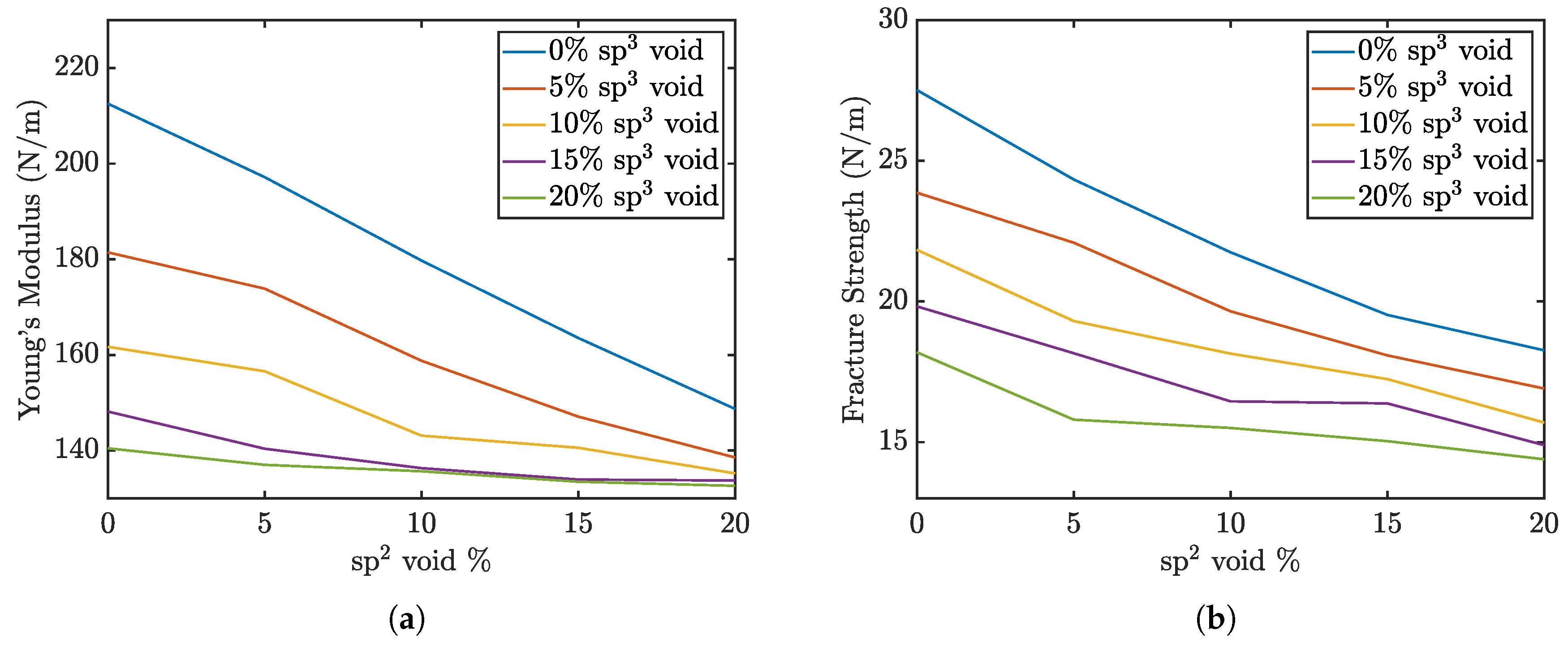
Figure 4.
Example of a crack atomic layout for penta-graphene
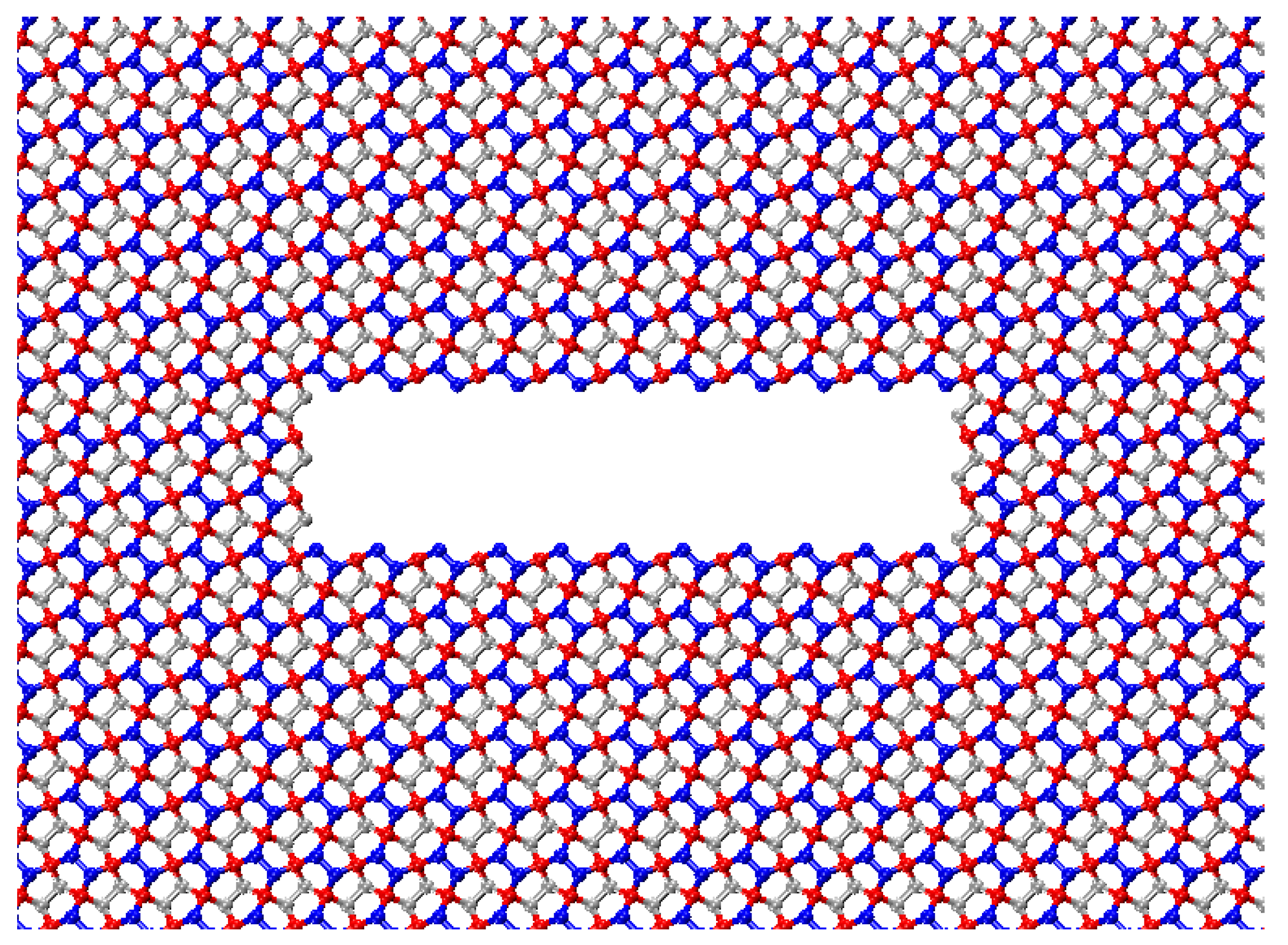
Figure 5.
Penta-graphene crack defect stress-strain curves for varying crack length (angstroms)
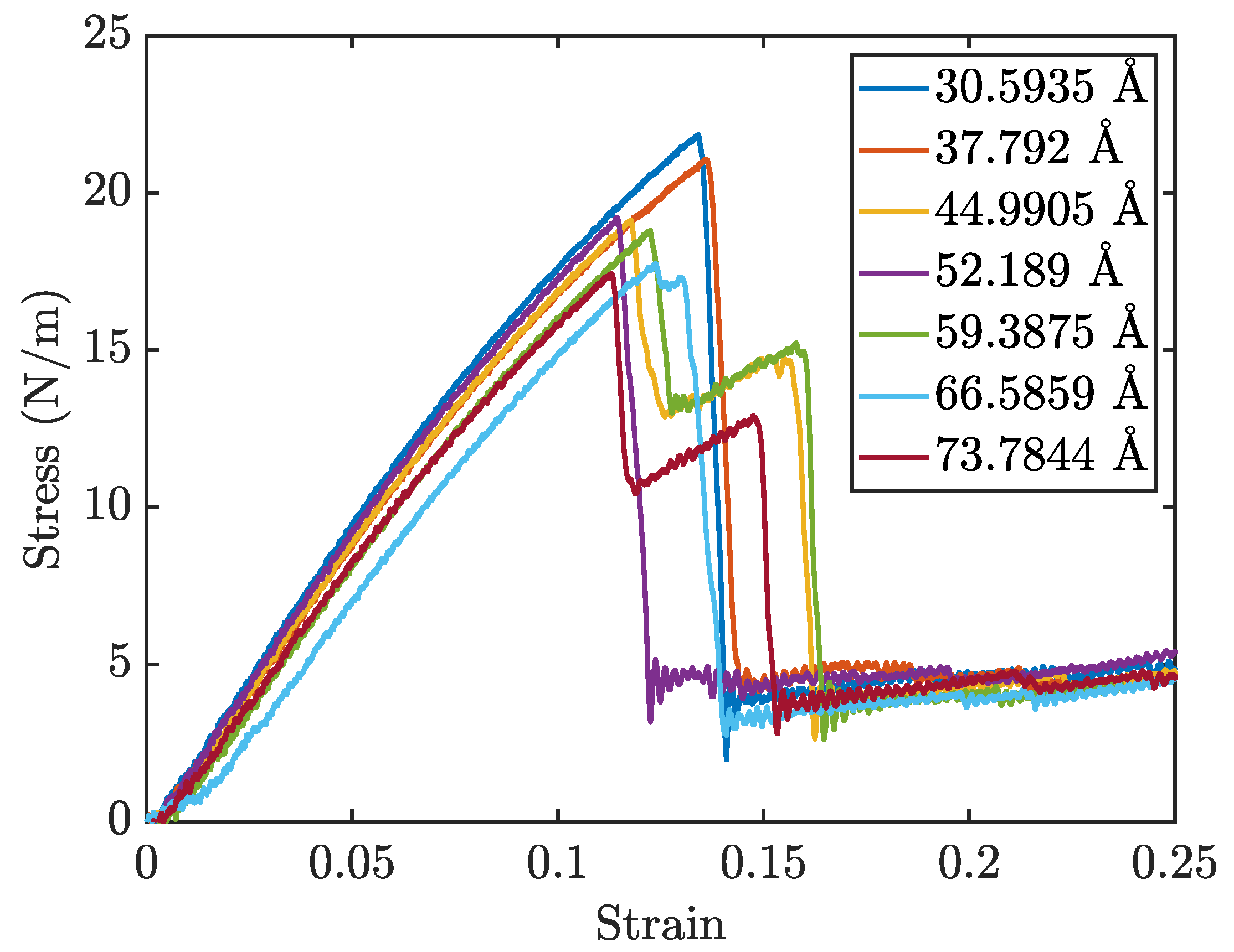
Figure 6.
Penta-graphene crack defect a) modulus of elasticity trend, b) fracture strength trend
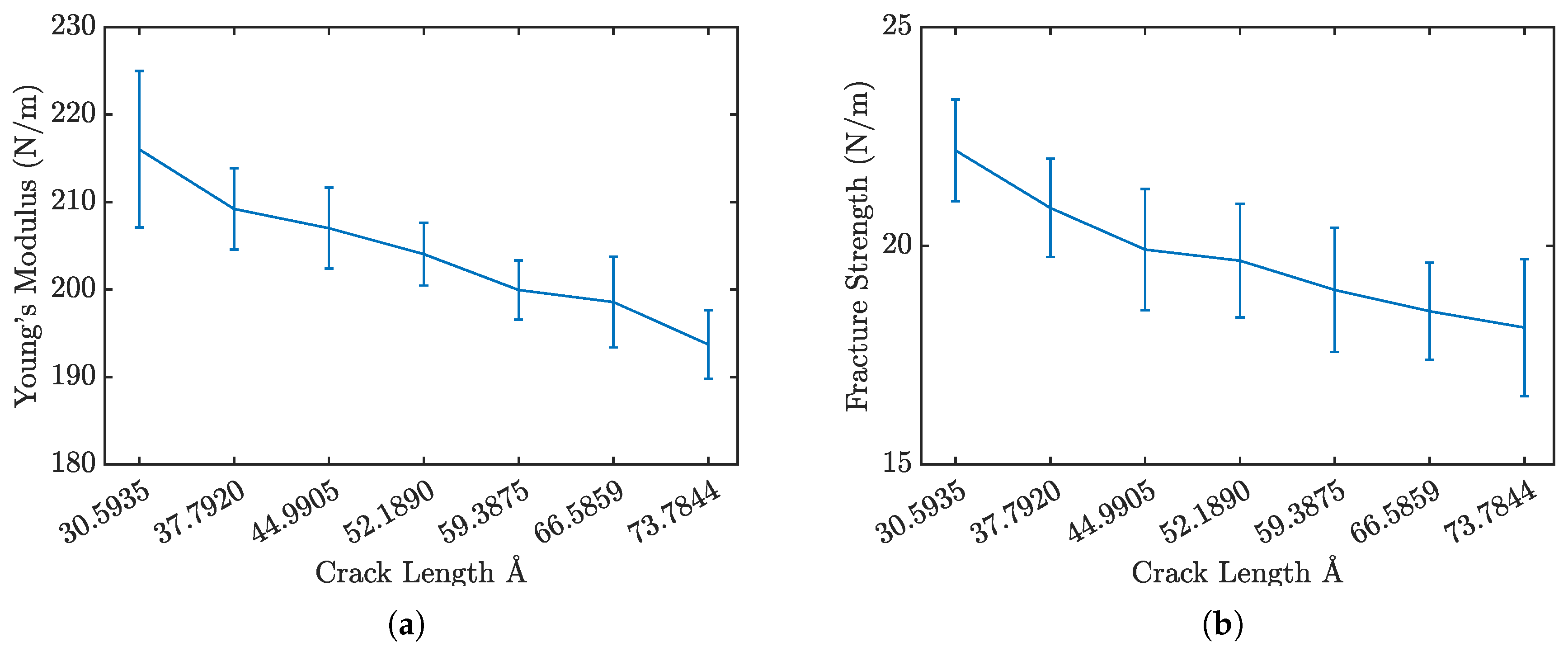
Figure 7.
Phase transition of penta-graphene with an initial crack of 66.59Å at strains a) 11.5%, b) 12.0%, c) 12.5%. The green highlighted region indicates carbon loops of greater than 5 atoms.
Figure 7.
Phase transition of penta-graphene with an initial crack of 66.59Å at strains a) 11.5%, b) 12.0%, c) 12.5%. The green highlighted region indicates carbon loops of greater than 5 atoms.
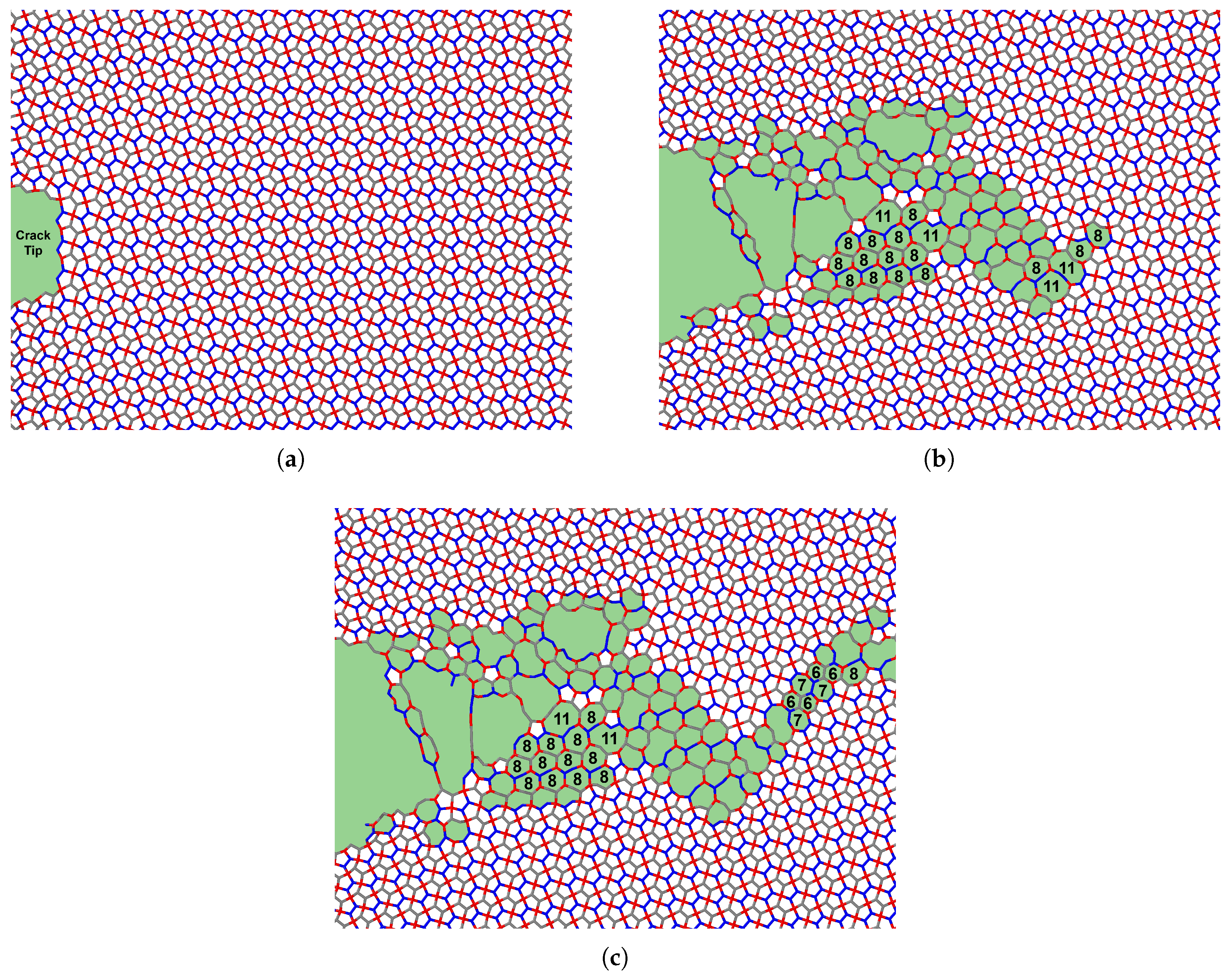
Figure 8.
Crack propagation of penta-graphene at strain values of a) 9.48%, b) 9.88%, c) 10.27%, d) 14.32% in a sheet with an initial crack length of 66.59Å , color coding depicts high axial stress as red, and low stress as blue.
Figure 8.
Crack propagation of penta-graphene at strain values of a) 9.48%, b) 9.88%, c) 10.27%, d) 14.32% in a sheet with an initial crack length of 66.59Å , color coding depicts high axial stress as red, and low stress as blue.
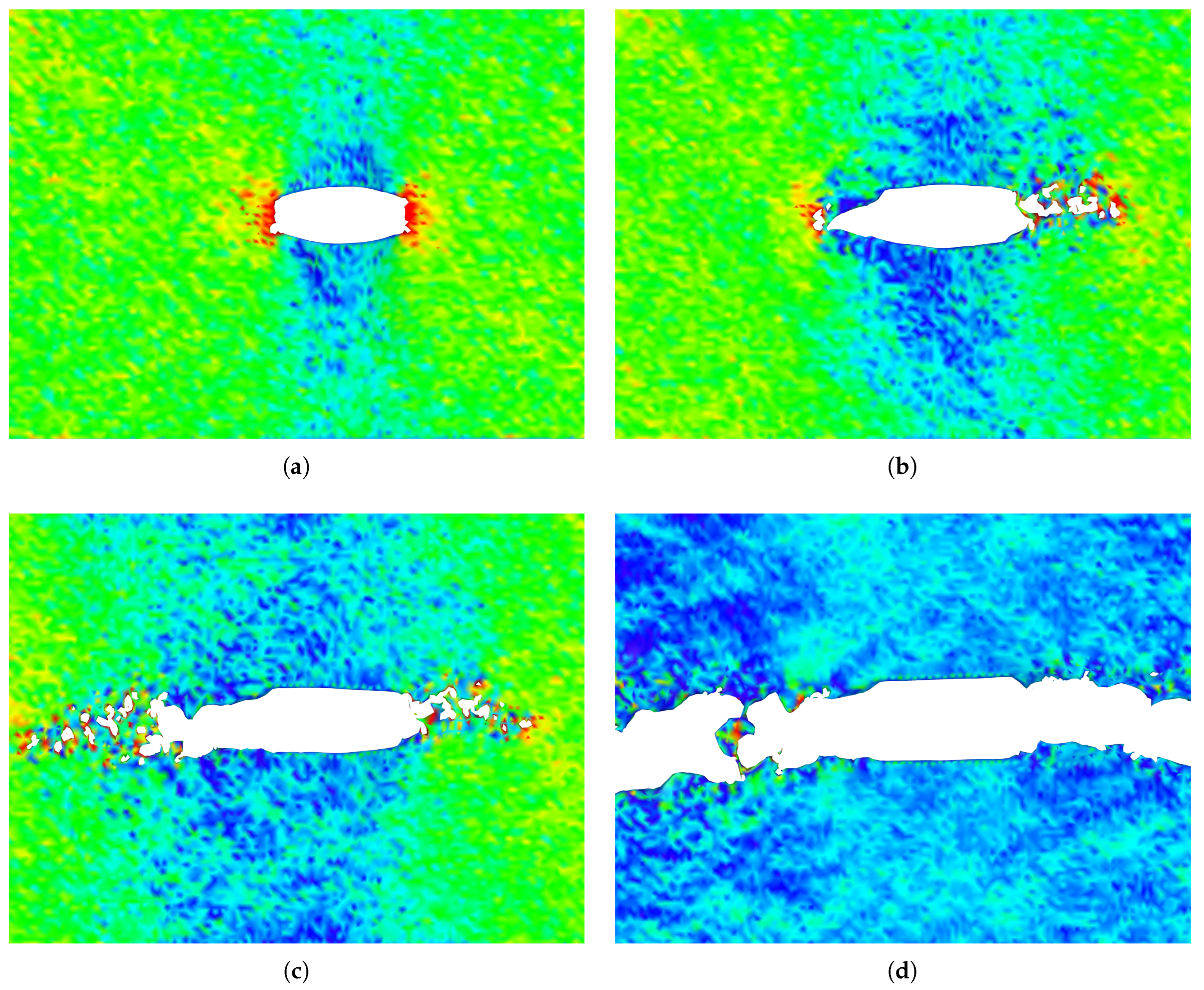
Figure 9.
Visualization of the expanded unit cells achieved by rotation for 18.43 degrees, 26.57 degrees, 36.87 degrees, and 45 degrees.
Figure 9.
Visualization of the expanded unit cells achieved by rotation for 18.43 degrees, 26.57 degrees, 36.87 degrees, and 45 degrees.
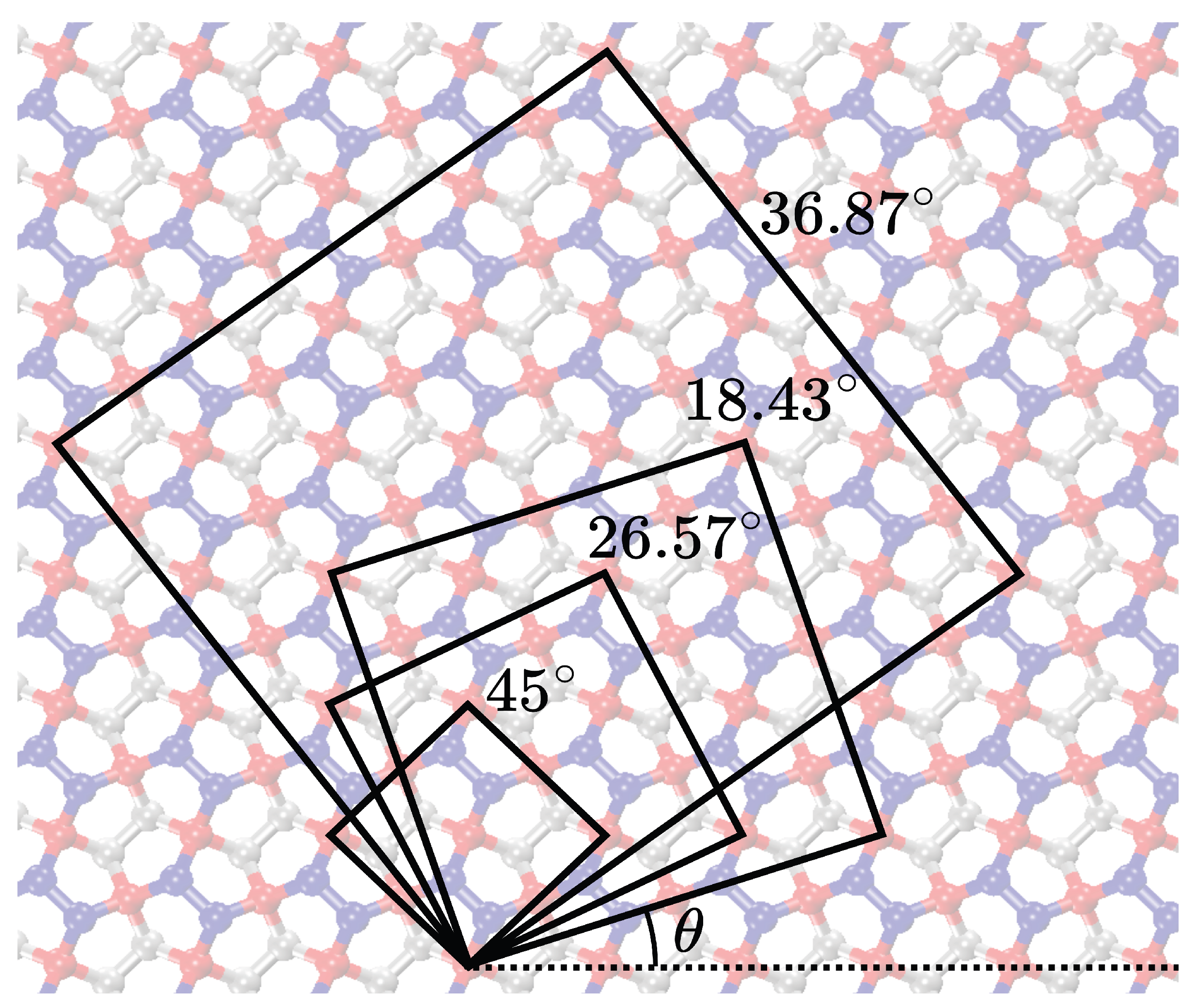
Figure 10.
Penta-graphene rotated load stress-strain curves
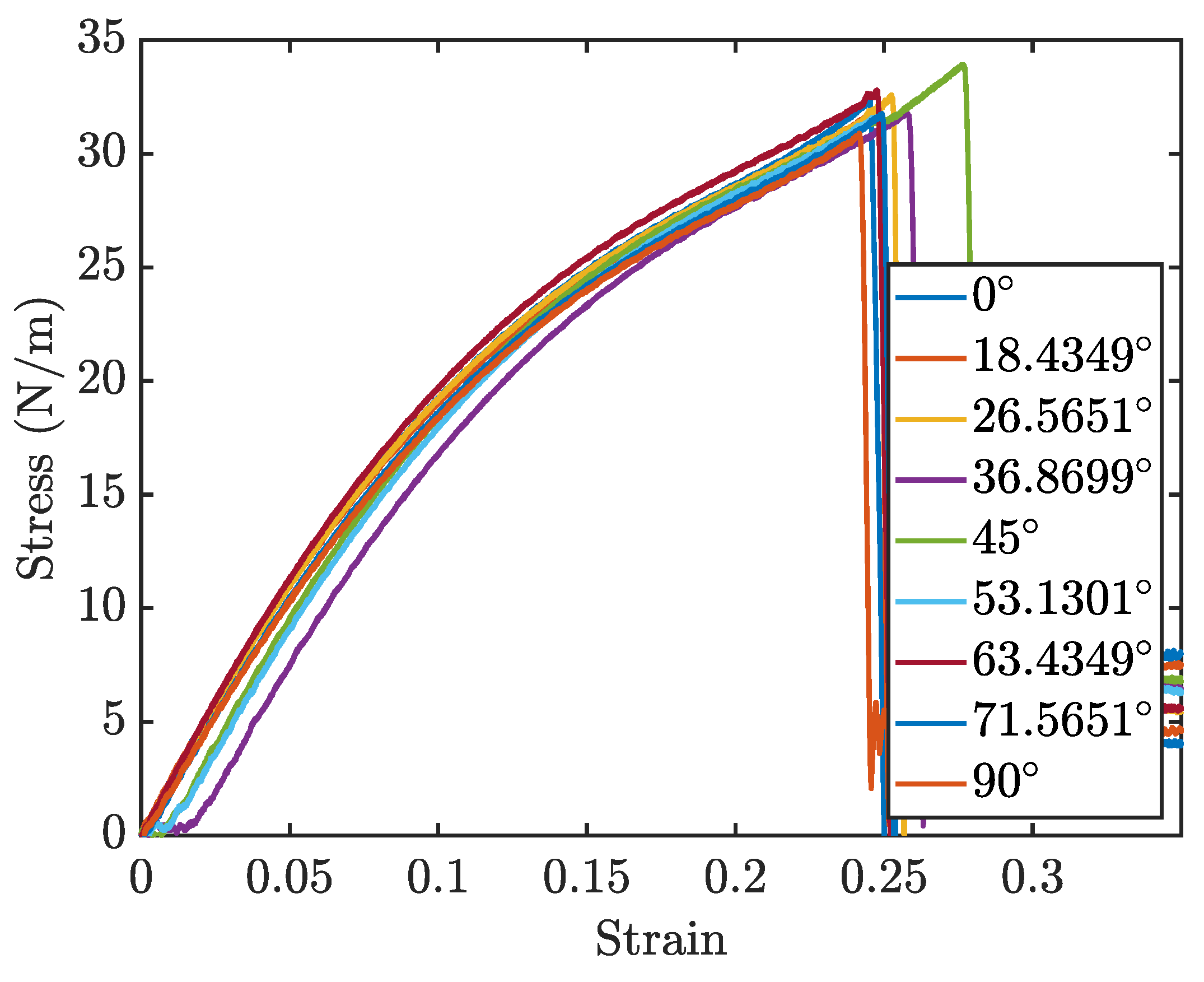
Figure 11.
Penta-graphene rotated load a) modulus of elasticity trend, b) fracture strength trend
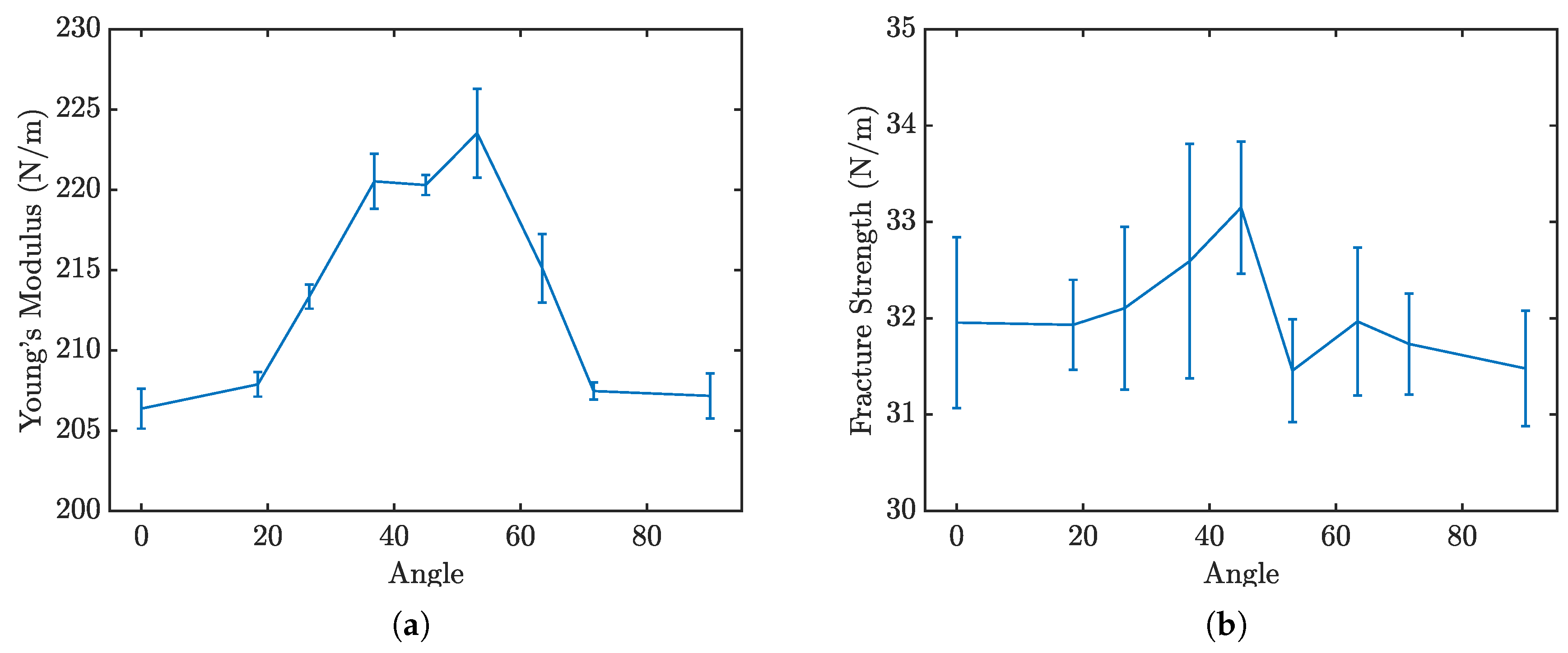
Figure 12.
Molecular dynamic domain for penta-graphene
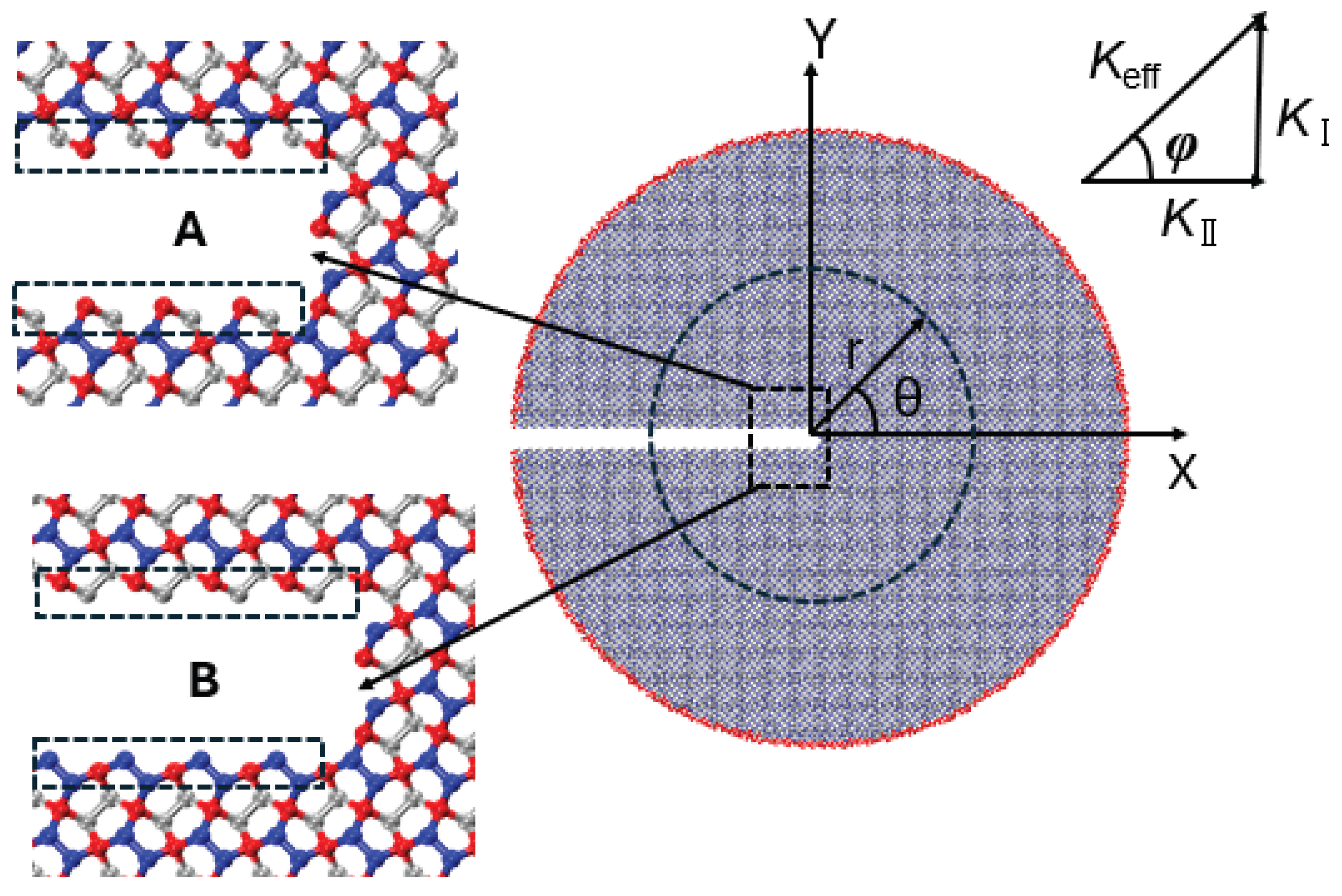
Figure 13.
Crack configuration A and B
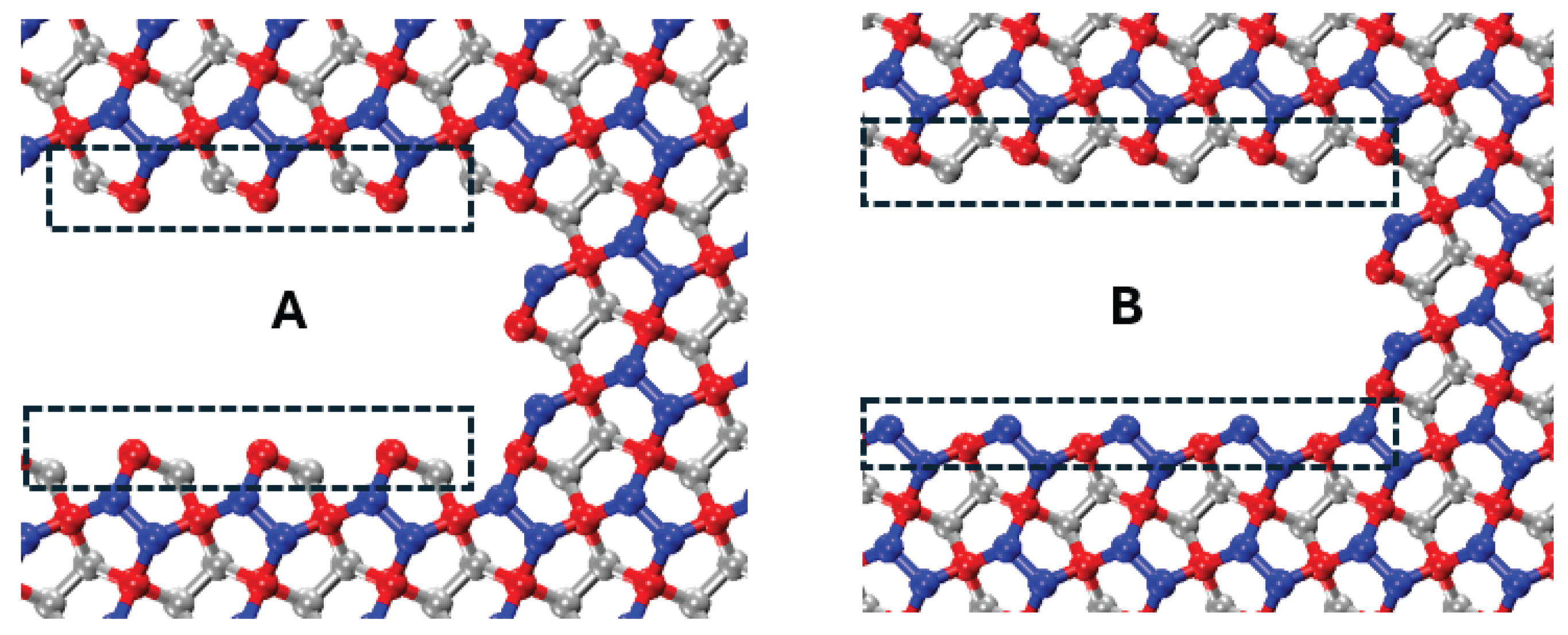
Figure 14.
Crack propagation path for different loading phase angles a) configuration A, b) configuration B
Figure 14.
Crack propagation path for different loading phase angles a) configuration A, b) configuration B
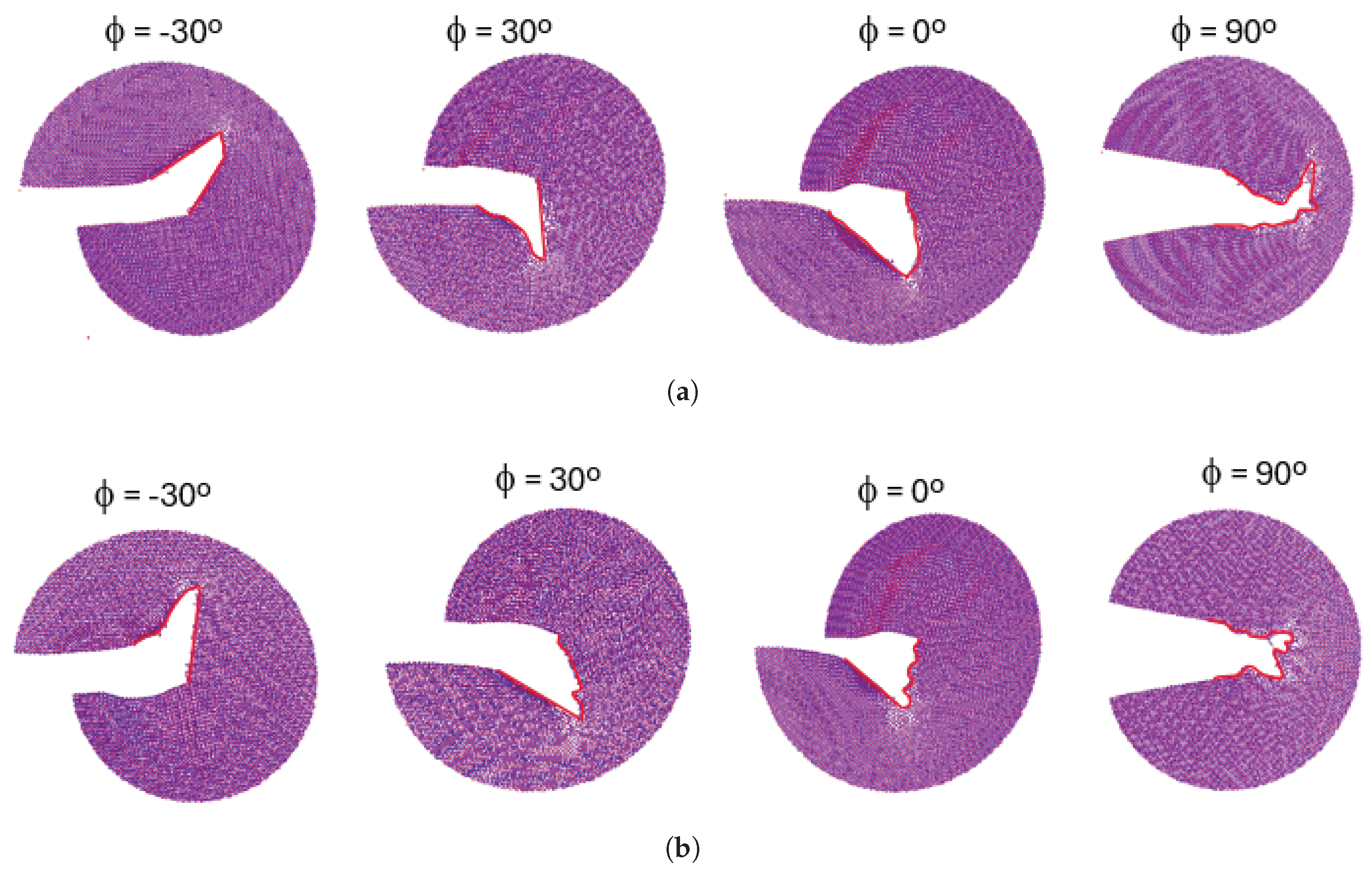
Figure 17.
Stress contour around the crack tip a) crack configuration A, b) crack configuration B
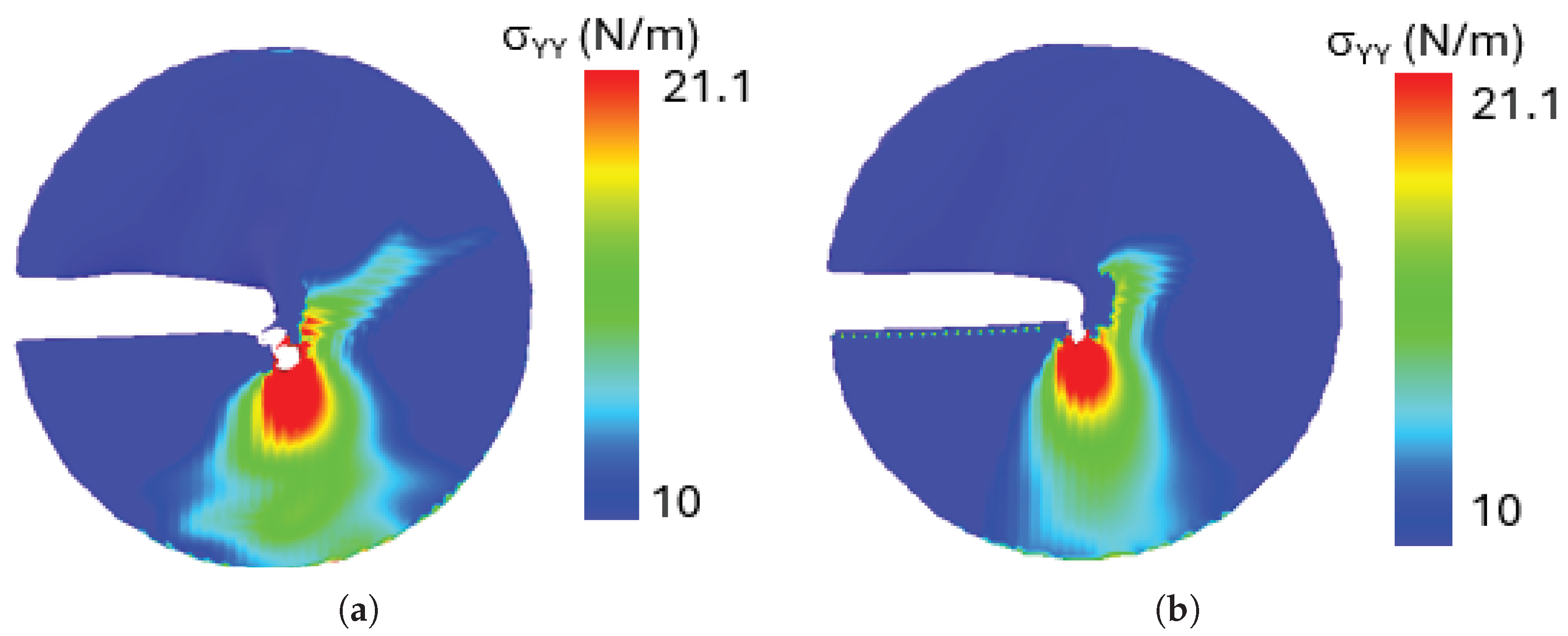

Table 1.
Structural and bonding parameters of penta- graphene.
| Property | – | – |
|---|---|---|
| Bond Length | = 1.55 Å | = 1.34 Å |
| Bond Character | Single bond | Double bond |
| Hybridization | Distorted |
Table 2.
Size of the expanded unit cells for the studied rotation angles in angstroms and atoms per cell.
Table 2.
Size of the expanded unit cells for the studied rotation angles in angstroms and atoms per cell.
| Rotation Angle | Unit Cell Size | Atoms Per Unit Cell |
|---|---|---|
| 0 | 3.6Å × 3.6Å | 6 |
| 18.43 | 11.38Å × 11.38Å | 60 |
| 26.57 | 8.05Å × 8.05Å | 30 |
| 36.87 | 18Å × 18Å | 150 |
| 45 | 5.09Å × 5.09Å | 12 |
| 53.13 | 18Å × 18Å | 150 |
| 63.43 | 8.05Å × 8.05Å | 30 |
| 71.57 | 11.38Å × 11.38Å | 60 |
| 90 | 3.6Å × 3.6Å | 6 |
Disclaimer/Publisher’s Note: The statements, opinions and data contained in all publications are solely those of the individual author(s) and contributor(s) and not of MDPI and/or the editor(s). MDPI and/or the editor(s) disclaim responsibility for any injury to people or property resulting from any ideas, methods, instructions or products referred to in the content. |
© 2025 by the authors. Licensee MDPI, Basel, Switzerland. This article is an open access article distributed under the terms and conditions of the Creative Commons Attribution (CC BY) license (http://creativecommons.org/licenses/by/4.0/).
Copyright: This open access article is published under a Creative Commons CC BY 4.0 license, which permit the free download, distribution, and reuse, provided that the author and preprint are cited in any reuse.


