Submitted:
01 May 2025
Posted:
07 May 2025
You are already at the latest version
Abstract
In this paper, A wideband and filtering monopole is presented for applying in remote terrestrial omnidirectional communication systems. The antenna consists of a sleeve monopole loaded by lumped parallel RLC circuit and an embedded high-low impedance structure in the sleeve section. The high-low impedance structure makes the antenna acquire filtering character in a compact structure. The sleeve structure and the lumped parallel RLC loads make the antenna a wideband radiation character in omni-direction. For verification, a prototype of the designed antenna, operating in 200-1500 MHz, is designed, fabricated and measured. The experiment results show that the antenna covers the design band with a VSWR<2.5, a measured gain>0 dB and a satisfactory filtering character from 1700 to 4000 MHz.
Keywords:
wideband monopole
; load antenna
; filtering antenna
1. Introduction
The development demand of high communication quality for terrestrial wireless omnidirectional communication puts forward the requirements of wideband, integration and anti-interference for antennas in the communication system [1,2,3,4]. The realization of a wideband monopole covering multiple bands of different systems could reduce complexity of multiple communication platform. On the other hand, a well-designed monopole with a large frequency ratio is a trend to meet the future needs of increasing communication capacity [5,6,7]. Besides, with the development of wireless communication, the demand of integrating RF front-end devices has become a trend in the design of modern wireless communication system. However, traditional monopole only works as an electromagnetic energy conversion device between closed wave guide space and open free space. To provide multifunctional ability for monopole, it is a good idea to combine antenna with filtering function, since antenna integrating with filtering function is popular in other antenna design, such patch antenna [8,9,10]. Integrating a filtering function in antenna not only can enhance electromagnetic immunity of communication system, but also can reduce the total size and weight of antenna [11,12,13].
Ordinary monopole with its simple linear structure is usually regarded as an open-end transmission line and shows the classic resonance character. A normal quarter-wavelength monopole only shows about ten percent relative bandwidth for VSWR<2 near resonant frequency [14,15], which is only suitable for the narrow band application. To meet the requirements of wideband application in terrestrial wireless omnidirectional wideband communication, it is eager to resolve the inherent resonant character in ordinary monopole. In wideband antenna design, the radiation bandwidth and impedance bandwidth of antenna have to be considered at the same time so as to realize a workable wideband front-end device for wideband communication system. For broadening the radiation bandwidth of monopole, loading ordinary monopole with lumped element is an effective way to alter current distribution on monopole and realizes the wideband radiation character while keeping the linear shape of monopole. With difference loading strategy [16,17,18,19], bandwidth could be broadened to thousand percent of relative bandwidth. As for broadening the impedance bandwidth of monopole, some appendix radiation structure such as hat or sleeve structure could be a good candidate, especially for electrical small monopole design. Numbers of novel variant of hat or sleeve structure play an important role in wideband antenna design [20,21,22,23,24,25].
Traditional monopole designs mainly focus on improving radiation character such as broadening radiation bandwidth or increasing radiation efficiency [26]. However, the traditional monopole does not have filtering function. As the core functional module of wireless communication system, filtering technology plays a key role in suppressing interference and purifying spectrum in the electromagnetic signal transceiver link. Its technology evolution has always been an important driving force to improve the performance of communication systems. In the traditional communication architecture, the filter and the antenna are designed independently. The filter, as a separate functional unit, needs to be optimized separately. And the antenna is only working for the radiation and reception of space electromagnetic signals. The electrical connection between antenna filter depends on the transmission line. This architecture leads to a double loss in the signal receiving path. The concatenation of lossy transmission lines and filters not only increases the size, weight and cost of the system, but also causes significant signal energy attenuation, especially in low signal-to-noise ratio scenarios, which seriously affects the receiving sensitivity.
To adapt with the demand of the integration development of RF front-end devices, integrating filtering character in monopole is a promising design. The design of filtering monopole could refer to other filtering antenna design. With the help of the mature filter synthesizing method, a simple way to realize filtering antenna is just introduce filtering structure at the port of the designed antenna to realize controllable passband and stopband [27,28,29]. By this method, although antenna could possess a filtering function straightforward, the filtering structure and the radiation structure still remain relatively independent. Consequently, the filtering character and the radiation character of the filtering antenna are still designed relatively separately and also, the total size is not compact enough. For consideration of size reduction and function integration, other way such as the fusion design method of filtering antenna could make use of antenna structure for realizing filtering function more effectively. In the fusion design method, filtering antenna design employs the eigenmode analysis of the designed antenna and then adjusts the structure of the radiator to realize filtering character [30,31,32]. The adjustment of the structure of the design antenna is easily implemented in patch antenna or antenna with cavity structure, since there are at least two dimension to adjust mode distribution on radiator. But for filtering monopole design, with the constrain of keeping the linear shape of monopole, it is hard to realize filtering character by the eigenmode analysis method due to no adequate place to adjust mode distribution on linear shape structure, especially for whip monopole that making use of wire as the radiator.
To achieve filtering character and compact size while obtaining wideband character in monopole design, this paper presents a wide band monopole integrating compactly with filtering function by a structure-reused technique that hybridizing the sleeve structure and the high-low impedance structure to realize filtering character for antenna. Section 2 addresses the design of the presented monopole. Starting from the familiarly simple linear monopole, the sleeve structure, the high-low impedance structure and the distributed lumped loads are employed gradually with little size expansion. Simulation shows that the presented monopole obtains wideband and filtering character in compact design. In section 3, the designed monopole is carried out with a fabricated prototype for verification. Tested result shows close the port character and radiation character between experiment and simulation. For comparison, Section 4 discusses the realized character of the design monopole against other similar designs of wideband monopole. The presented monopole realizes wideband character while obtains filtering superiorly in monopole design. Section 5 concludes this work gives a promising sight on the presented monopole.
2. Antenna Design and Configuration
2.1. Antenna Configuration
The overall design scheme of the presented monopole is depicted in Figure 1. The initial structure is a familiarly simple whip monopole with narrow band character. By introducing a sleeve structure, the monopole’s bandwidth can be broadened to some extent with no obvious size expansion. So, the lower radiator of the initial monopole is converted into the inner conductor of the sleeve structure. The outer conductor of the sleeve plays a role as a part of the radiator of the sleeve monopole. The lower part of the initial monopole and the inner side of the sleeve composes a transmission line in the sleeve monopole now. And then, for obtaining a filtering function for the monopole, the lower part of the initial monopole in the sleeve structure is replace with a multistage metal structure. This multistage structure accompanying with the inner conductor composes a high-low impedance transmission line with a required filtering function. Since the filtering function is obtained by just the replacement of the inner conductor of the sleeve structure, no any size expansion take place in the introduction of filtering function for the monopole. The presented monopole is design with filtering function in compact size. After the filtering structure is designed, the upper part of the monopole in current design is still a normal whip radiator. For broadening the bandwidth of monopole further, the distributed lumped elements are loaded on the radiator. Acceptable filtering character and radiation character can be obtained by optimizing the size of the embedded high-low impedance transmission line in the sleeve and the value and the position of the loaded element at the same time.
The detail structure of the presented wideband filtering monopole is shown in Figure 2. The monopole is fed on ground by common 50 ohm coaxial port as the normal feed network of ordinary monopole. For applying in mobile vehicles or air craft communication, the working band is design from 200 MHz to 1500 MHz. To have lower VSWR character around 200 MHz, the total length H1 of the presented monopole as Figure 2 shown is selected as 30 cm. The sleeve made of a hollow cylinder with its diameter D2=5 cm is design encloses the lower part of the radiator with length H1=10 cm. And the bottom of the sleeve is connected to ground. For rejecting common frequency band of 2450 MHz and some 5G communication bands in 3000-4000 MHz, the design monopole requires a lowpass filtering character above the design working band. In the hollow of the sleeve, a multistage structure is designed and works as a high-low impedance transmission line with a low pass filtering character. The detail of high-low impedance transmission line is discussed in section 2.2. The upper radiator more like traditional monopole and also made of a hollow tube with diameter D1=1.5 cm. But for broadening the band width of the presented monopole further, three lumped circuits are loaded on the radiator of the presented monopole. All lumped circuits are made of parallel RLC element to adjust the current distribution on the radiator resulting in wide band omni-direction radiation character. The detail of these distributed lumped loads is addressed in section 2.3.
2.2. Design of Filtering Structure
The High-low impedance transmission line design start from a five order Chebyshev lowpass circuit as Figure 3 (a) illustrated to obtain a rejection character below -20 dB from 1700 MHz to 4000 MHz. By applying Richards’s transformation and Kuroda’s identities [33], the lowpass circuit in Figure 3 (a) can be converted to another circuit in a form of altered impedance transmission line as Figure 3 (b) shown. To realized the lowpass circuit of Figure 3 (b) in the sleeve structure in Figure 2, the high-low impedance transmission line is designed in the sleeve as illustrated in Figure 5 (a). The inner surface of the sleeve works as the outer conductor of the high-low impedance transmission line. Since this filtering structure is placed at the lower part of the monopole as Figure 2 shown, the high-low impedance structure is also working as a supporter for the upper part of the monopole. Although the high-low impedance structure is made of metal, the high impedance transmission line is too thin to support the upper part of the monopole. Even though some Teflon supports could be introduced to maintain the stability of the structure, extra design of this Teflon supporter would lead to a complex design of this filtering structure. Taking into account the support problem, the high-low impedance transmission is designed by two side patch structure as Figure 5 (b) shown. The dielectric substrate works as the supporter for the high-low impedance structure and the upper part of the monopole at the same time.
The detail architecture of the top view the high-low impedance transmission line based on substrate embedded in the sleeve is illustrated in Figure 6. Two copper patches etched on a substrate which is made of Teflon with relative permittivity of 2.1 work as the inner conductor of the high-low impedance transmission line. These two copper patches are connected to each other by numbers of via holes with radius of 1.5 mm to analog the filtering structure in Figure 5 (a). The width of substrate W1 is 48 mm which is the same as the inner radius of the sleeve. But the width of the etched low impedance section of the high-low impedance transmission line W2 is 47 mm which is slightly shorter than W1. So, the substrate can also work as supporter for inner conductor resided in transmission line. The other sizes depicted in Figure 6 deduced by Richards’ transformation [33] are calculated from the lowpass filtering circuit in Figure 3 (b). The length of each low impedance section is optimized for compensating for the parasitic capacitance effect. As Figure 7 shown the optimized high-low impedance transmission line based on substrate achieves the desired low pass character with cut-off frequency resided around 1500 MHz and a stop band with S21 below -20dB from 1700 MHz up to 4000 MHz. Due to the fact that the low impedance line is tending to resonance around 4000 MHz, the rejection property from 3000 MHz to 4000 MHz become worse. However, the rejection property is still below -20 dB in these band and meets the rejection specification.
2.3. Wide Band Filtering Monopole
After the filtering structure designed, the high -low impedance structure based on substrate is arranged in the sleeve as Figure 2 depicted. For obtaining satisfied radiation property, three lumped loads are arranged on the designed monopole as Figure 2 depicted. Each load is a parallel RLC circuit. The designed monopole is simulated by MoM to analog the electrical character. The positions of each load and the value of each load element is optimized for satisfactory electrical character. The optimized parameters of the loads are listed in Table 1. The positions of the loads are measured from ground. All the optimized values of each element are easy access in practical implementation.
The optimized gain in omni direction is all greater than 0 dB in the concerned band as shown in Figure 8. For comparison, the gain of ordinary monopole and the gain of ordinary sleeve monopole in omni direction are also plotted in Figure 8. These two monopoles have narrower bandwidth due to the occurrent of gain zero in omni direction. But the presented monopole has not experienced such gain zero in omni direction since the loads of the presented monopole has been properly designed. Figure 9 and Figure 10 illustrate the E-plane patterns and the H-plane patterns of the designed monopole at some typical frequencies in the concerned band. The optimized monopole has relatively uniform radiation character in omni direction in the concerned band. The radiation efficiency of the design monopole is above 40% across the working band as shown in Figure 11. For wideband application, the radiation efficiency is acceptable. As Figure 12 shown, the optimized monopole obtains VSWR below 3, which is an acceptable port property for wideband application.
3. Experiment and Result Analysis
A fabricated prototype is shown in Figure 13 in which the sleeve is separated apart for illustration. The designed monopole is fed by a common 50 ohm N-connector. The experiment is carried out in outdoor open half-space environment, as shown in Figure 14. The transmitting antenna and the receiving antenna are separated 20 m away for measurement of the far field at 200 MHz by employing the criterion of 10λ for far-field judgment. The measured VSWR and the simulated VSWR of the presented monopole are shown in Figure 15. It can be seen that the presented monopole could cover a wide band of 200–1500 MHz with a VSWR < 3. Acceptable agreement between the simulation and measurement can be found. The differences between the simulation and measurement may come from the fact that the practical load circuits are fabricated with a little space in contrast to the point load in the simulation. The measured gain and filtering character of the presented monopole is shown in Figure 16. There is satisfactory agreement between the measurement and simulation. Figure 16 also shows the gains of an ordinary monopole and an ordinary sleeve with the same size. The presented not only has advantage in bandwidth but also in advantage in filtering character with stopband below -20 dB from 1700 MHz up to 4000 MHz.
4. Discussion
Table 2 shows the performance comparison between the presented monopole and other reference monopoles. Ref. [34] and [4] presented some design with wideband character, but their gains are lower. Besides, there are no filtering character in that designs. In Ref. [29] and [35], the presented monopoles are all designed with filtering character and higher gain, but they can only be used for narrow band application. In sum, wideband and filtering character are achieved in this paper, the structure is simple and compact in size.
5. Conclusions
A loaded sleeve monopole with wideband and filtering character is presented. By designing a high-low impedance structure in placement of the inner conductor of the sleeve, filtering character is achieved. Since no extra structure is introduced, the design realizes structure reuse and results in compact size. Lumped load technique is also employed to adjust the current distribution on radiator for broadening the bandwidth. The presented monopole was tested from 200 MHz to 4000 MHz with stable gain above 0 dB in passband from 200 MHz up to 1500 MHz and a satisfactory stopband below -20 dB from 1700 MHz up to 4000 MHz. With the merits of wide bandwidth, filtering, omnidirectional character and compact size, the presented monopole is a good candidate for vehicle terrestrial wireless omnidirectional communication.
Author Contributions
All authors have significantly contributed to the research presented in this manuscript; J.M. presented the main idea and wrote the manuscript; W.C. and X.Y. reviewed and revised the manuscript. All authors have read and agreed to the published version of the manuscript.
Funding
This work was supported by the National Natural Science Foundation-Regional Foundation of China (62461014), Guangxi Natural Science Fund of China (2025GXNSFAA069602).
Data Availability Statement
Data are available based upon reasonable request from the corresponding author.
Conflicts of Interest
The authors declare no conflict of interest.
References
- Khan Imran; Qiu Hongbing; Rahman Saeed U. U.; Ahmad Tariq. Compact design of monopole antenna for SWB application with high BDR. Microwave and Optical Technology Letters 2023, 65, 1656–1663. [Google Scholar] [CrossRef]
- Shuxin Zheng; Nan Yang; Xiaoming Chen; Zhen-Yuan Zhang; Bingyi Qian; Ahmed A. Kishk. Wideband Cup Dielectric Resonator Antenna with Stable Omnidirectional Patterns. Applied Computational Electromagnetics Society Journal 2024, 39, 908–915. [Google Scholar]
- Ramya; Alharbi Fares; Kumar Naresh. Design and Analysis of Dual Monopole Antennas for Long-Term Evolution and Ultra-Wideband Applications Narrow and Wide Band Variants. Journal of Nanoelectronics and Optoelectronics 2024, 19, 716–723. [Google Scholar] [CrossRef]
- Ding Andi; Gan Theng Huat; Shen Zhongxiang. Design of a Compact and Wideband Printed Monopole Antenna with Stable Omnidirectional Radiation Patterns. IEEE Antennas and Wireless Propagation Letters 2024, 23, 1483–1487. [Google Scholar] [CrossRef]
- Abbasi Arand Bijan Abdollahvand Mousa, Katoch Kanishka, Ghosh Saptarshi. A novel and compact ultra-wideband printed monopole antenna with enhanced bandwidth and dual-band stop properties. Microwave and Optical Technology Letters 2024, 66. [Google Scholar]
- Xu Bowen Duan Chaoqian, Zhang Lei, Wang Jiangfan, Zhang Guozhi. Research on Miniaturized and Wideband UHF Sensing Technology for Partial Discharge Detection of Power Equipment Based on Serpentine Bending. IEEE Sensors Journal 2024, 24, 23951–23959. [Google Scholar] [CrossRef]
- Su Huafeng Shuai Sun, Jiao Yang, Ou Jun-Hui, Zhang Xiu Yin. Ultra-Wideband Omnidirectional Antenna with Stable Radiation Patterns Using CMA. IEEE Transactions on Vehicular Technology 2024, 73, 10788–10792. [Google Scholar] [CrossRef]
- Jianfeng Qian; Benito Sanz Izquierdo; Steven Gao; Hanyang Wang; Hai Zhou; Huiliang Xu. A Cascaded Resonator Decoupling Network for Two Filtering Antennas. IEEE Antennas and Wireless Propagation Letters 2023, 22, 3187–3191. [Google Scholar] [CrossRef]
- Yongliang Zhang; Tianyu Liu; Linping Feng; Xianfang Zhang; Sai-Wai Wong. A Coupling Matrix Synthesis Design for Filtering Antenna With Good Out-of-Band Suppression. IEEE Antennas and Wireless Propagation Letters 2023, 22, 1582–1586. [Google Scholar] [CrossRef]
- Junlei Guo; Yongpin Chen; Deqiang Yang; Kai Sun; Jin Pan; Sihao Liu. Design of Wideband Filtering Patch Antenna Array With High Aperture Efficiency and Good Filtering Performance. IEEE Transactions on Antennas and Propagation 2024, 72, 974–979. [Google Scholar] [CrossRef]
- Boskovic Ljubodrag B Platt Jori M, Filipovic Dejan S. Wideband Biconical Antenna with Embedded Band-Notch Resonator. IEEE Transactions on Antennas and Propagation 2024, 72, 2921–2925. [Google Scholar] [CrossRef]
- Sahu Bhagirath Verma Ravi Prakash, Gupta Ashish. Compact Modified Elliptical-Shaped Ultra-wideband Filtering Antenna with Improved Band-Edge Selectivity. IETE Journal of Research 2024, 70, 8097–8109. [Google Scholar] [CrossRef]
- Kumar Trivesh Patel Abhishek, Parihar Manoj Singh. Highly Selective Ultra-wideband Filtenna with Triple Band Notch and Wide Stop Band Rejection for UWB Communication and Sensing Applications. IETE Technical Review.
- Gary, A. Thiele Warren L. Stutzman. Antenna Theory and Design, Third Edition. John Wiley & Sons: 2012; pp. 240-245.
- Constantine, A. Balanis. Antenna Theory Analysis and Design, Fourth Edition. John Wiley & Sons: 2016; pp. 167-256.
- Amir Boag, A. Boag, E. Michielssen, R. Mittra. Design of Electrically Loaded Wire Antennas Using Genetic Algorithms. IEEE Transactions on Antennas and Propagation 1996, 44, 687–695. [Google Scholar] [CrossRef]
- R. Mittra Z. Altman, A. Boag. New Designs of Ultra Wide-band Communication Antennas Using a Genetic Algorithm. IEEE Transactions on Antennas and Propagation 1997, 45, 1494–1501. [Google Scholar] [CrossRef]
- C. M. Butler S.D. Rogers, A.Q. Martin. Design and Realization of GA-optimized Wire Monopole and Matching Network with 201 Bandwidth. IEEE Transactions on Antennas and Propagation 2003, 51, 493–502. [Google Scholar] [CrossRef]
- Boris Levin. Wide-range and Multi-frequency Antenna. CRC Press: Boca Raton, FL, USA, 2019; pp. 36-62.
- Sun Qin Dongjie, Baohua, Zhang Rui. VHF/UHF Ultrawideband Slim Monopole Antenna with Parasitic Loadings. IEEE Antennas and Wireless Propagation Letters 2022, 21, 2050–2054. [Google Scholar] [CrossRef]
- Tang Ming-Chun Duan Yunlu, Wu Zhentian, Zhang Zhehao, Yi Da, Li Mei. Omnidirectional-Radiating, Vertically Polarized, Wideband, Electrically Small Filtenna. IEEE Transactions on Circuits and Systems II-Express Briefs 2023, 70, 1380–1384. [Google Scholar]
- Michishita Naobumi Mizutani Tomokazu, Sato Hiroshi, Koyanagi Yoshio, Morishita Hisashi. Increasing bandwidth of orthogonally polarised omnidirectional antenna composed of halo and sleeve antennas. IET Microwaves Antennas & Propagation 2023, 17, 565–573. [Google Scholar]
- Phung Thanh Tung Ta Son Xua, Nguyen Khac Kiem, Dao-Ngoc Chien, Nguyen-Trong Nghia. Low-Profile Dual-Polarized Composite Patch-Monopole Antenna with Broadband and Widebeam Characteristics. IEEE ACCESS 2023, 11, 87104–87110. [Google Scholar] [CrossRef]
- Deng Changjiang Zhu Yuqing. Wideband Dual-Polarized Endfire Phased Array Antenna with Small Ground Clearance for 5G mmWave Mobile Terminals. IEEE Transactions on Antennas and Propagation 2023, 71, 5469–5474. [Google Scholar] [CrossRef]
- Zeng Junwen Chen Zhuozhu, Wang Jing. Compact Ultrawideband H-Plane Horn Antenna Inspired by Modified Double-Sleeve Monopole. IEEE Antennas and Wireless Propagation Letters 2024, 23, 2767–2771. [Google Scholar] [CrossRef]
- Michael, E. Baginski James S. Smith. Thin-Wire Antenna Design Using a Novel Branching Scheme and Genetic Algorithm Optimization. IEEE Transactions on Antennas and Propagation 2019, 67, 2934–2941. [Google Scholar]
- Chen Fu-Chang Xiang Kai-Ran, Tan Qian, Chu Qing-Xin. High-Selectivity Filtering Patch Antennas Based on MultiPath Coupling Structures. IEEE Transactions on Microwave Theory and Techniques 2021, 69, 2201–2210. [Google Scholar] [CrossRef]
- Hao-Tao Hu, Wu Geng-Bo, Chan Ka Fai, Chan Chi Hou. V-Band Dual-Polarized Filtering Transmitarray Antenna Enabled by a Planar Filtering Illumination Source.pdf>. IEEE Transactions on Antennas and Propagation 2022, 70, 9184–9197. [Google Scholar] [CrossRef]
- Wu Lin Ling Su Huafeng, Zhang Yao, Zhang Jun, Xu Hui Liang, Zhang Xiu Yin. Circuit Modeling and Parameter Extracting of a Filtering Series-Fed Antenna. IEEE Transactions on Microwave Theory and Techniques 2023, 71, 1640–1653. [Google Scholar] [CrossRef]
- Chen Si Yang Wanchen, Xue Quan, Che Wenquan, Shen Guangxu, Feng Wenjie. Novel Filtering Method Based on Metasurface Antenna and Its Application for Wideband High-Gain Filtering Antenna with Low Profile. IEEE Transactions on Antennas and Propagation 2019, 67, 1535–1544. [Google Scholar] [CrossRef]
- Yang Wanchen Xun Mengzhu, Feng Wenjie, Zhang Yingqi, Xue Quan, Che Wenquan. A Differentially Fed Dual-Polarized Filtering Patch Antenna with Good Stopband Suppression.pdf>. IEEE Transactions on Circuits and Systems II-Express Briefs 2021, 68, 1228–1232. [Google Scholar]
- Chen Fu-Chang Yuan Hang, Chu Qing-Xin. A Wideband and High Gain Dual-Polarized Filtering Antenna Based on Multiple Patches. IEEE Transactions on Antennas and Propagation 2022, 70, 9843–9848. [Google Scholar] [CrossRef]
- David, M. Pozar. Microwave Engineering, Fourth Edition. John Wiley & Sons: 2012; pp. 416-417.
- J. Y. Zhao, Cao, W. P., Lu L. C. Design of a Low-cost Broadband Miniaturized Sleeve Loaded Monopole Antenna. 2022 IEEE 10th Asia-Pacific Conference on Antennas and Propagation.
- Hu Wei Chen Zhan, Lin Cong, Li Changjiang, Wen Lehu, Jiang Wen, Gao Steven. Wideband Horizontally Omnidirectional, Polarization-Reconfigurable, Cylindrical Antenna Based on Combined Common and Differential Modes. IEEE Transactions on Antennas and Propagation 2025, 73, 600–605. [Google Scholar] [CrossRef]
Figure 1.
The design scheme of the presented wideband filtering monopole.
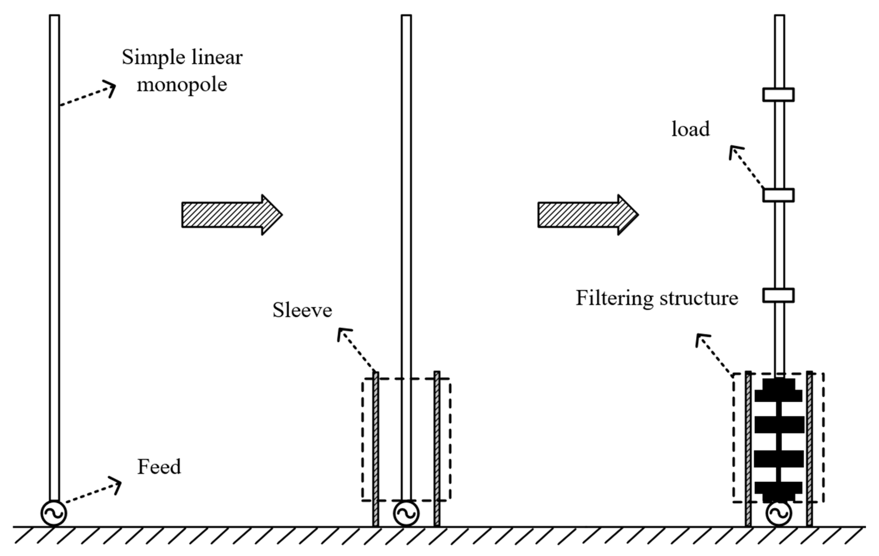
Figure 2.
The detail configuration of the presented wideband filtering monopole.
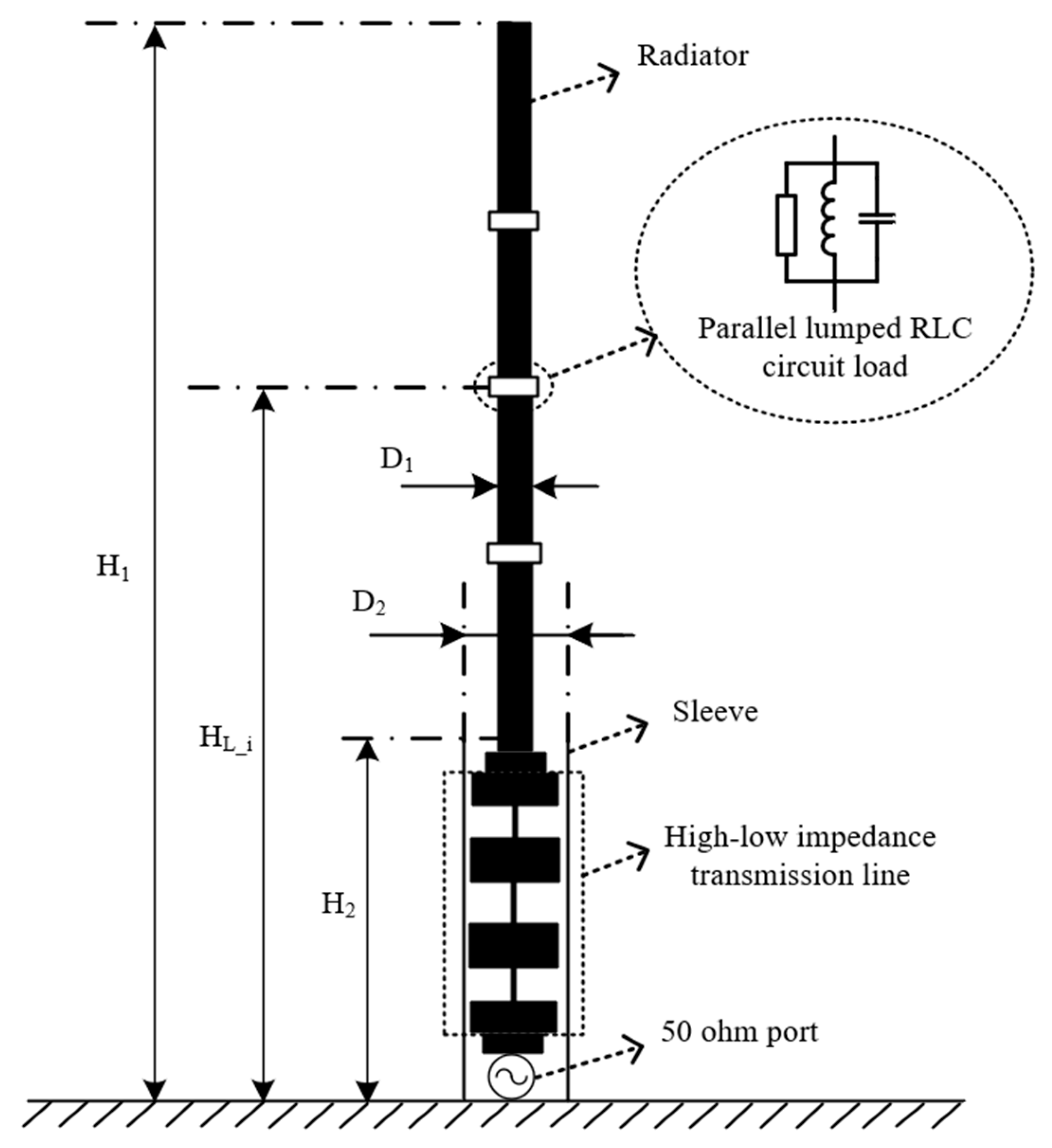
Figure 3.
Lowpass circuit. (a) Five orders RC ladder Chebyshev lowpass circuit; (b) The converted high-low impedance lowpass circuit.
Figure 3.
Lowpass circuit. (a) Five orders RC ladder Chebyshev lowpass circuit; (b) The converted high-low impedance lowpass circuit.
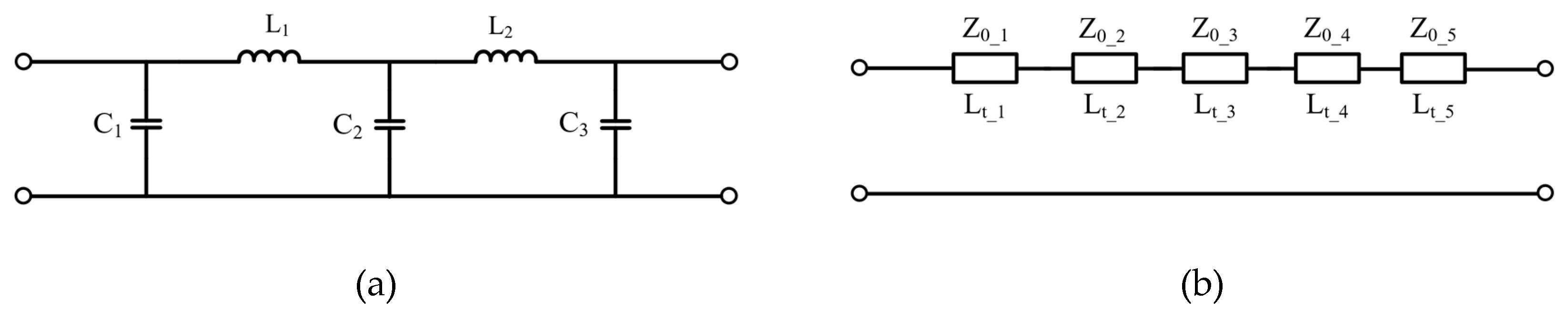
Figure 5.
Filtering structure. (a) High-low impedance transmission line; (b) High-low impedance transmission line based on substrate.
Figure 5.
Filtering structure. (a) High-low impedance transmission line; (b) High-low impedance transmission line based on substrate.
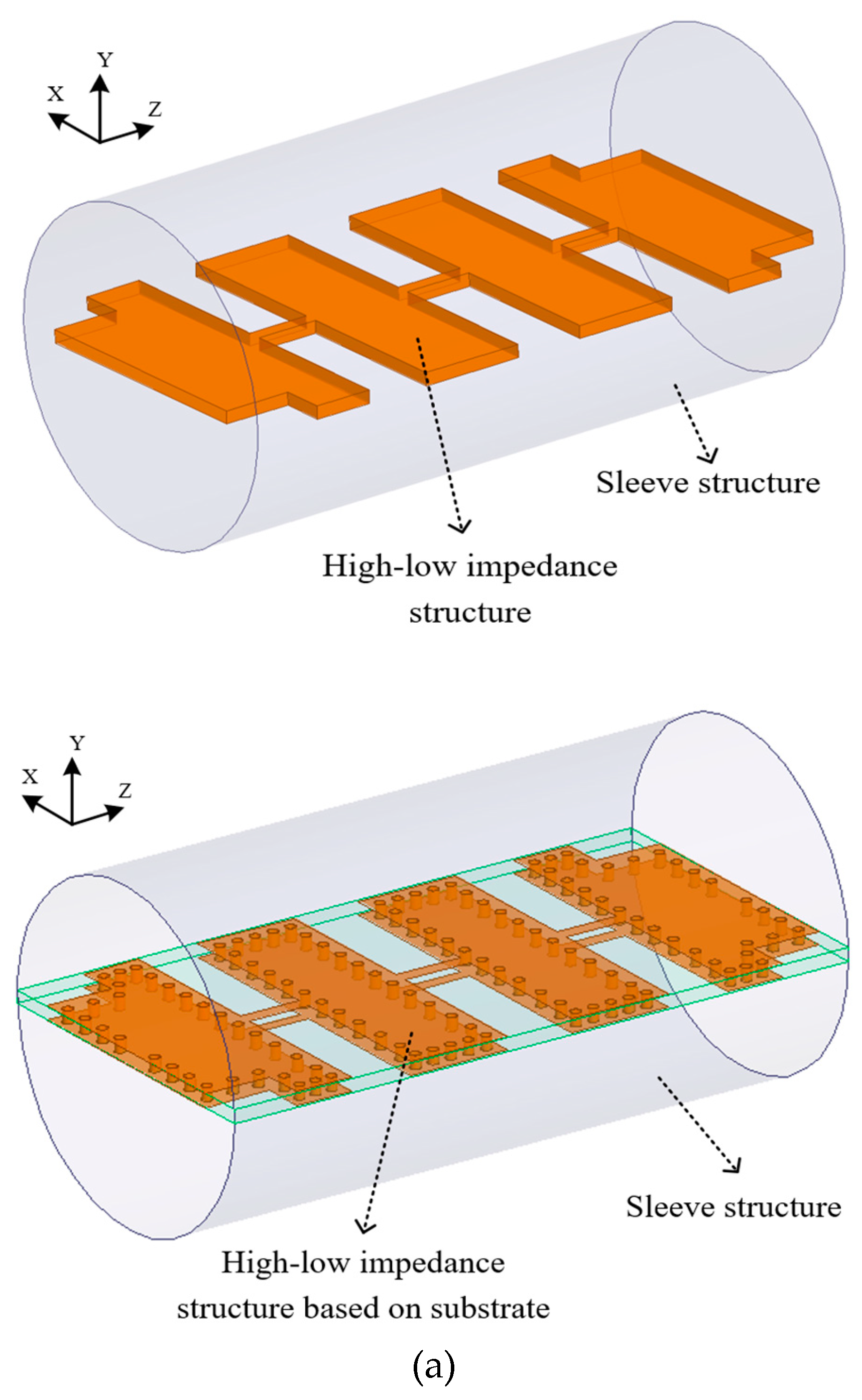
Figure 6.
Top view of the high-low impedance structure based on dielectric substrate (W1=48 mm, W2=47 mm, H3=95.4 mm, H4=10 mm, H5=8.5 mm, H6=9.2 mm, H7=15 mm, H8=10 mm, R1=1.5 mm).
Figure 6.
Top view of the high-low impedance structure based on dielectric substrate (W1=48 mm, W2=47 mm, H3=95.4 mm, H4=10 mm, H5=8.5 mm, H6=9.2 mm, H7=15 mm, H8=10 mm, R1=1.5 mm).
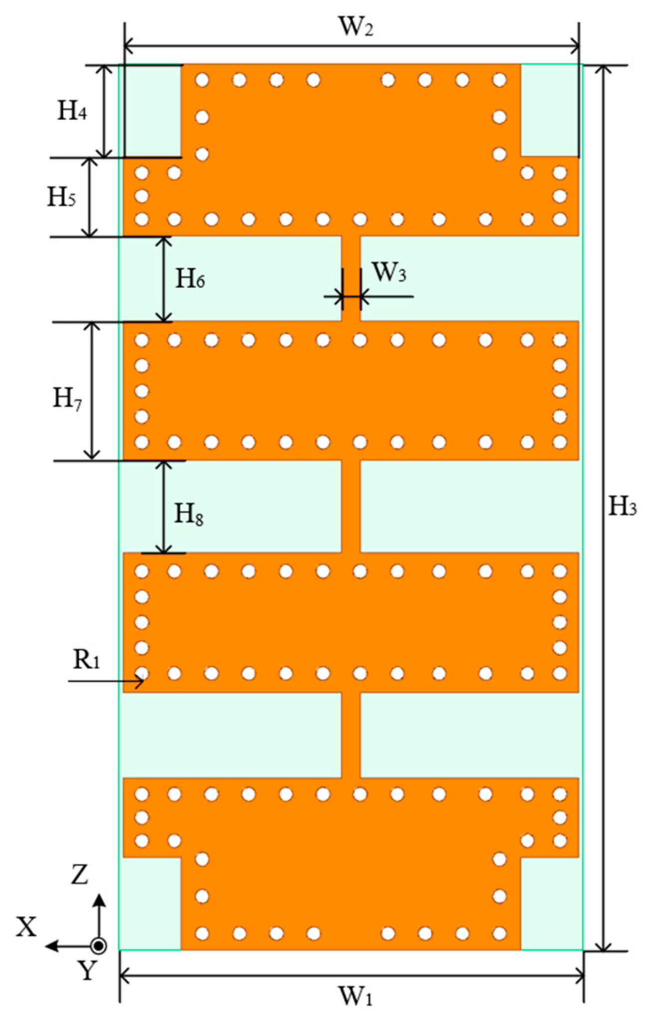
Figure 7.
The filtering character of the high-low impedance structure.
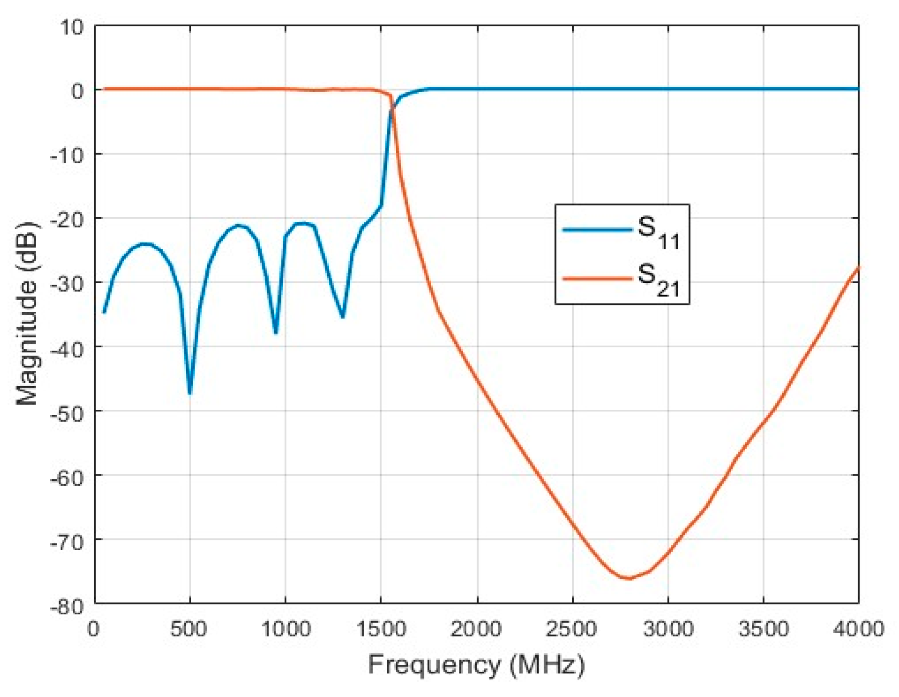
Figure 8.
Gain of the designed monopole in passband.
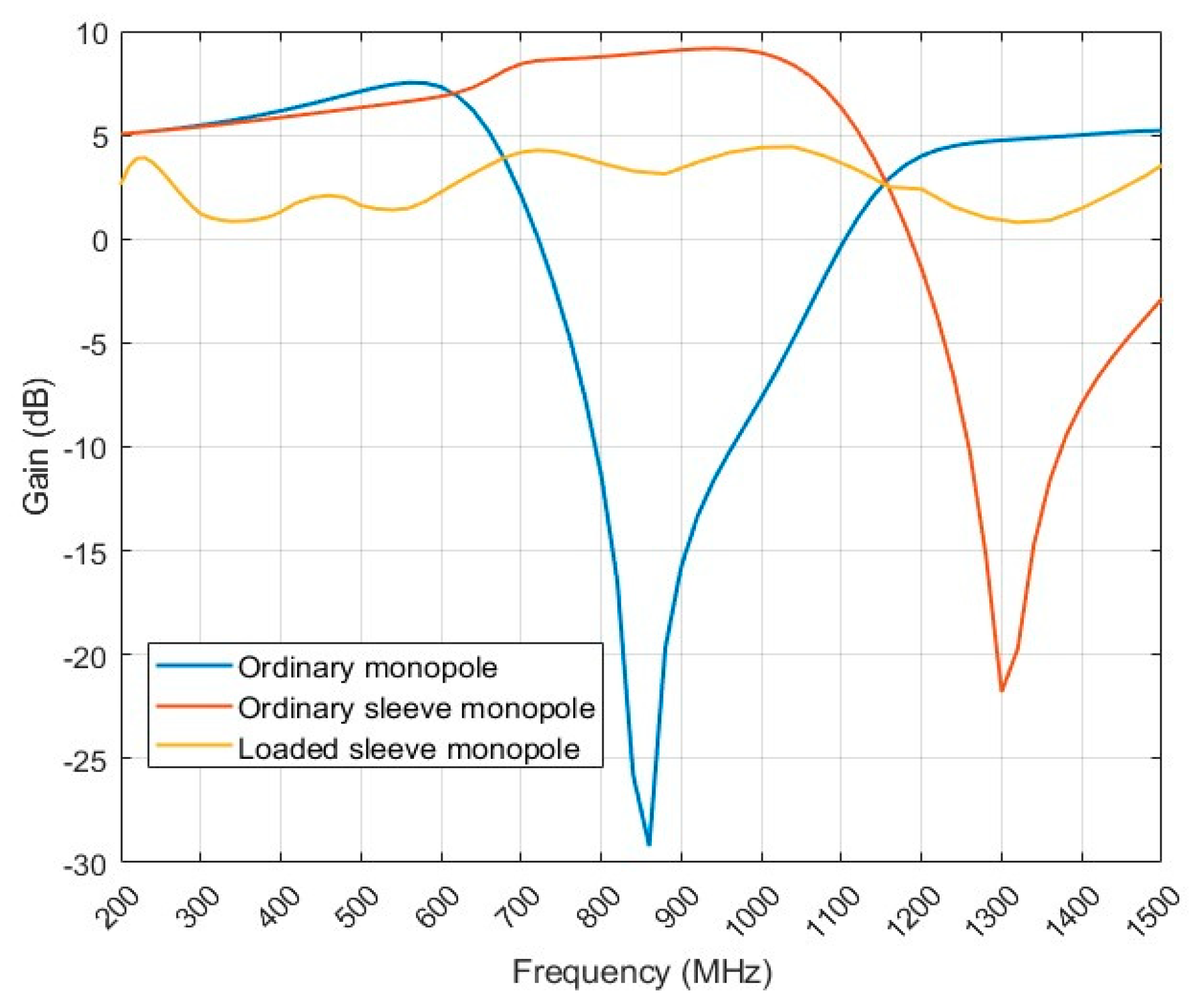
Figure 9.
E-plane patterns of the designed monopole.
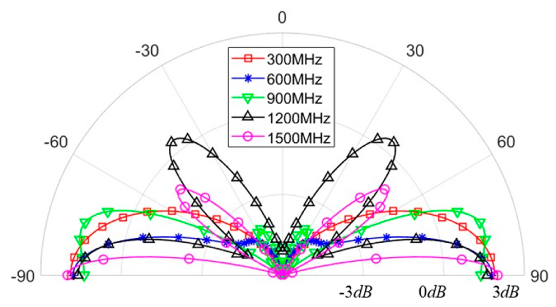
Figure 10.
H-plane patterns of the designed monopole.
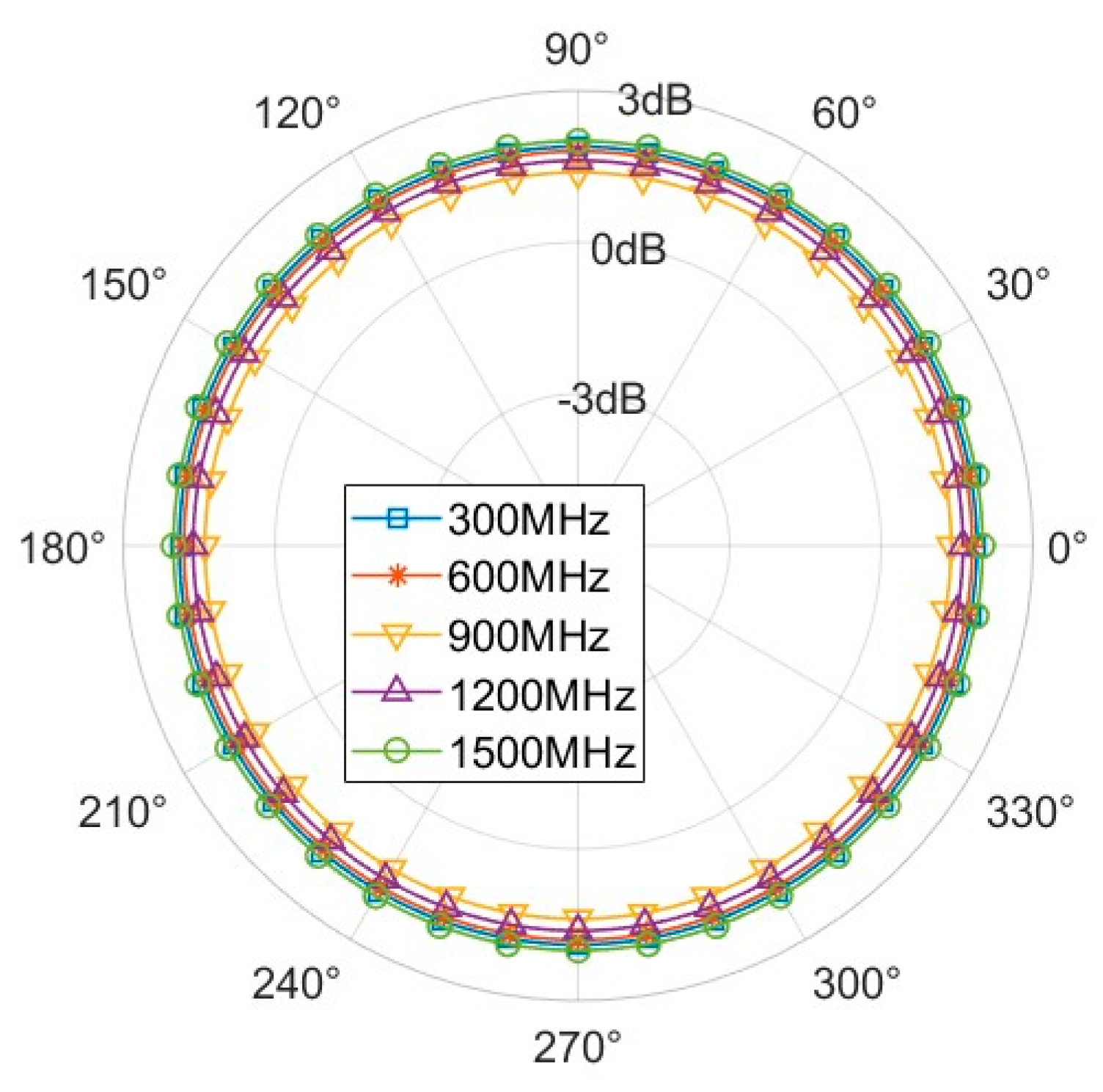
Figure 11.
Radiation efficiency of the designed monopole.
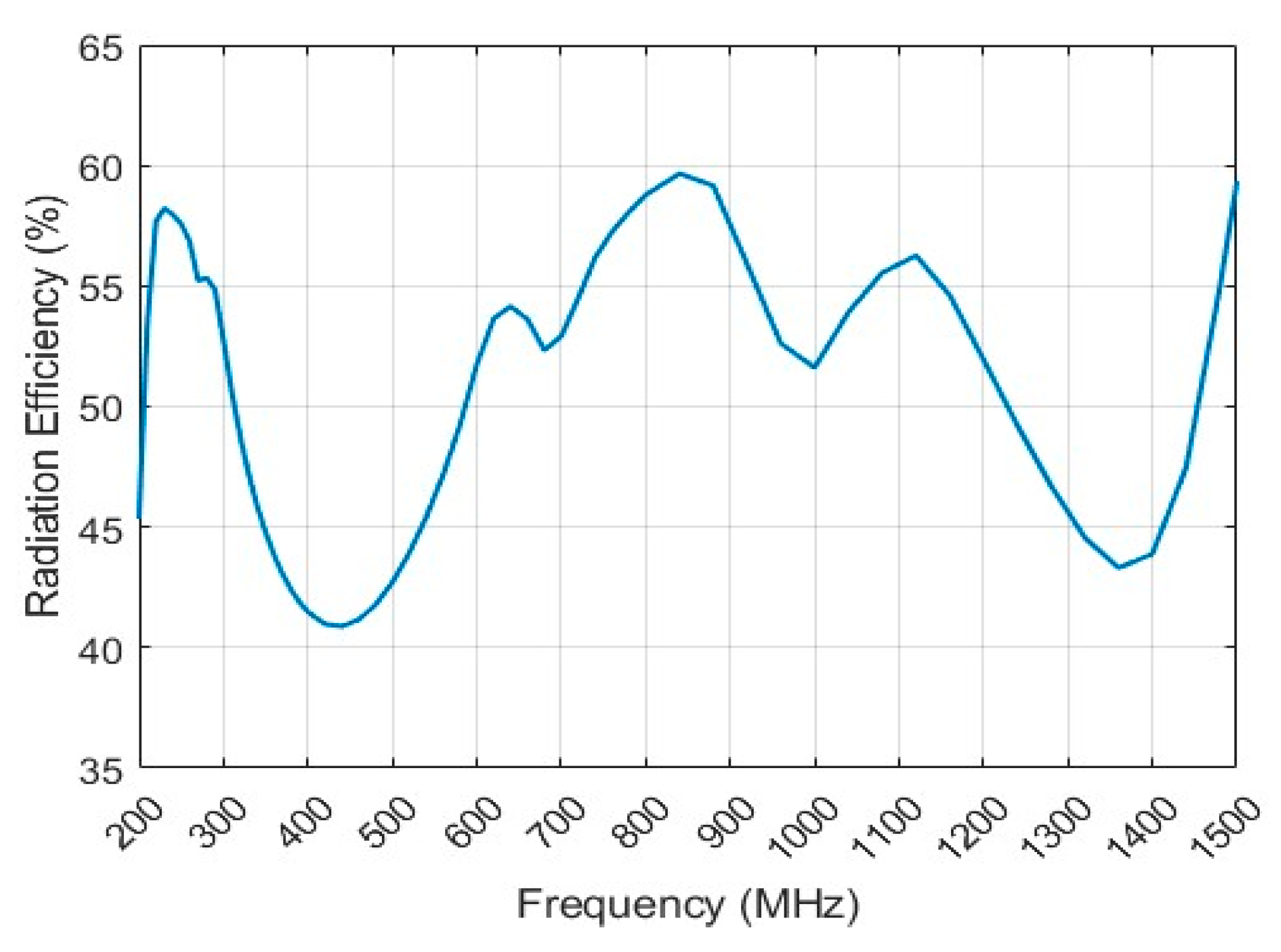
Figure 12.
VSWR of the designed monopole.
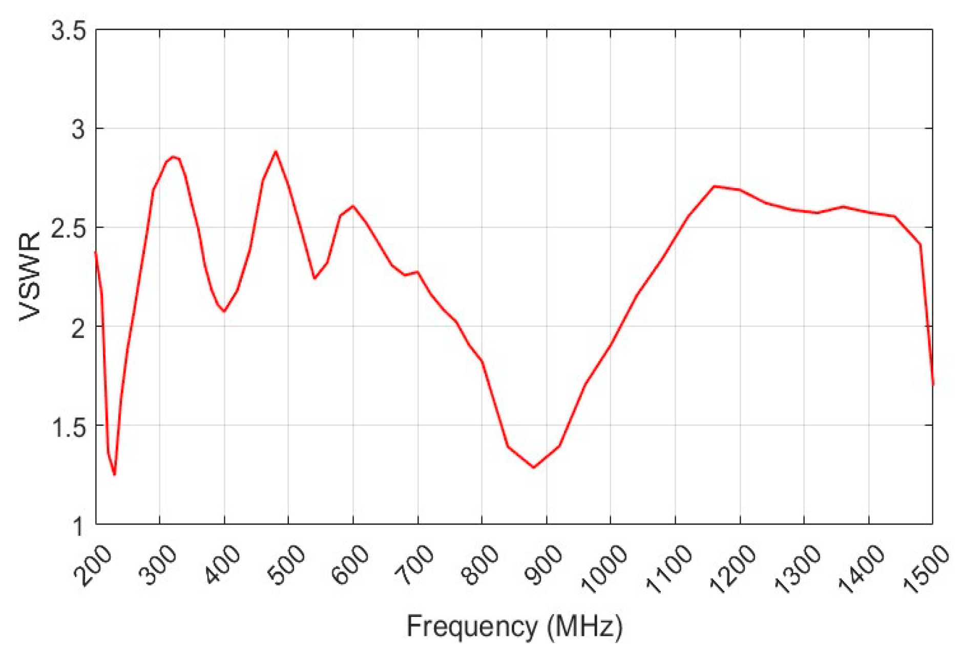
Figure 13.
Fabricated prototypes of the designed monopole.
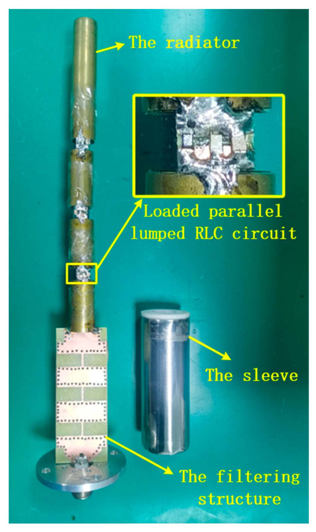
Figure 14.
Experiment in outdoor open half-space environment.
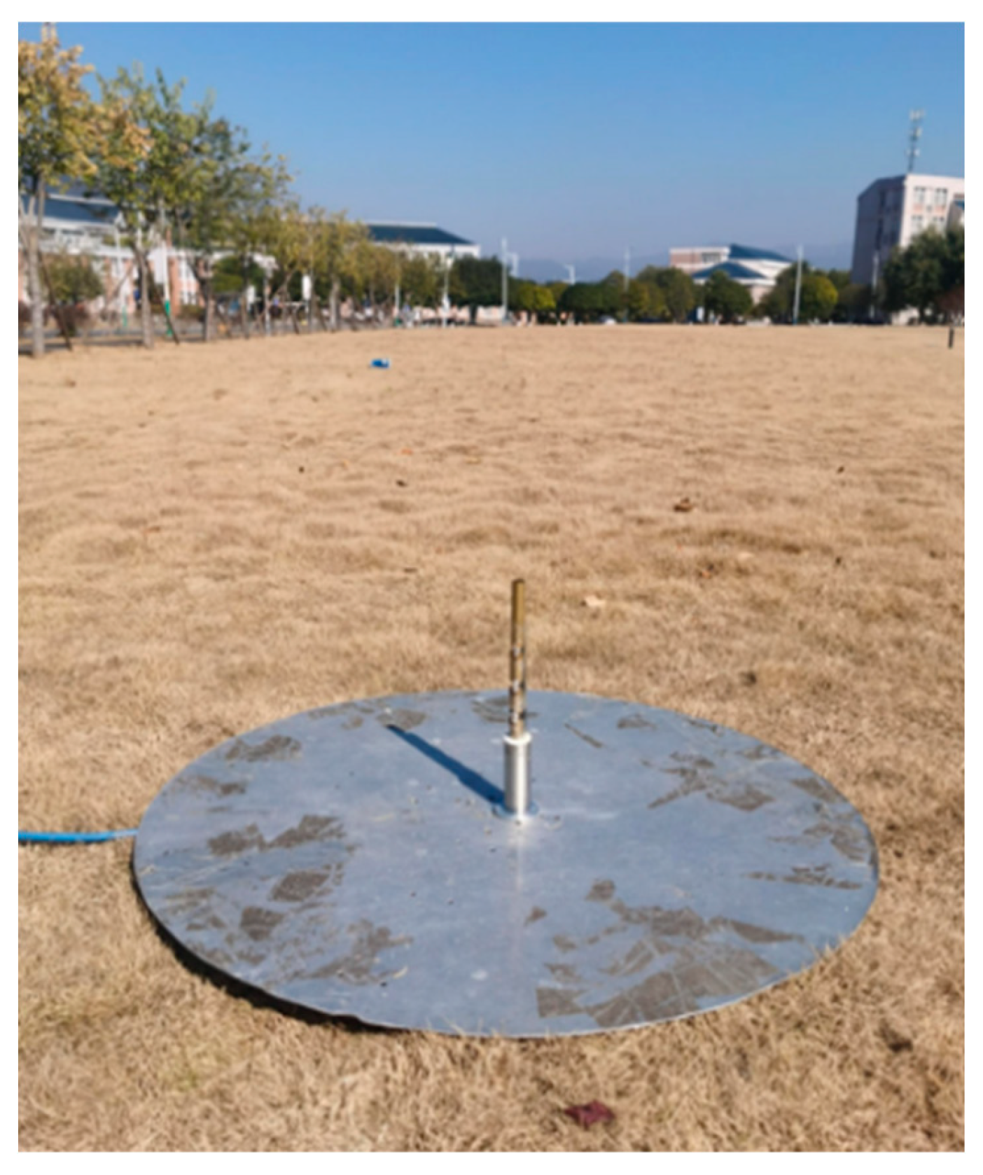
Figure 15.
The measured and simulated VSWRs.
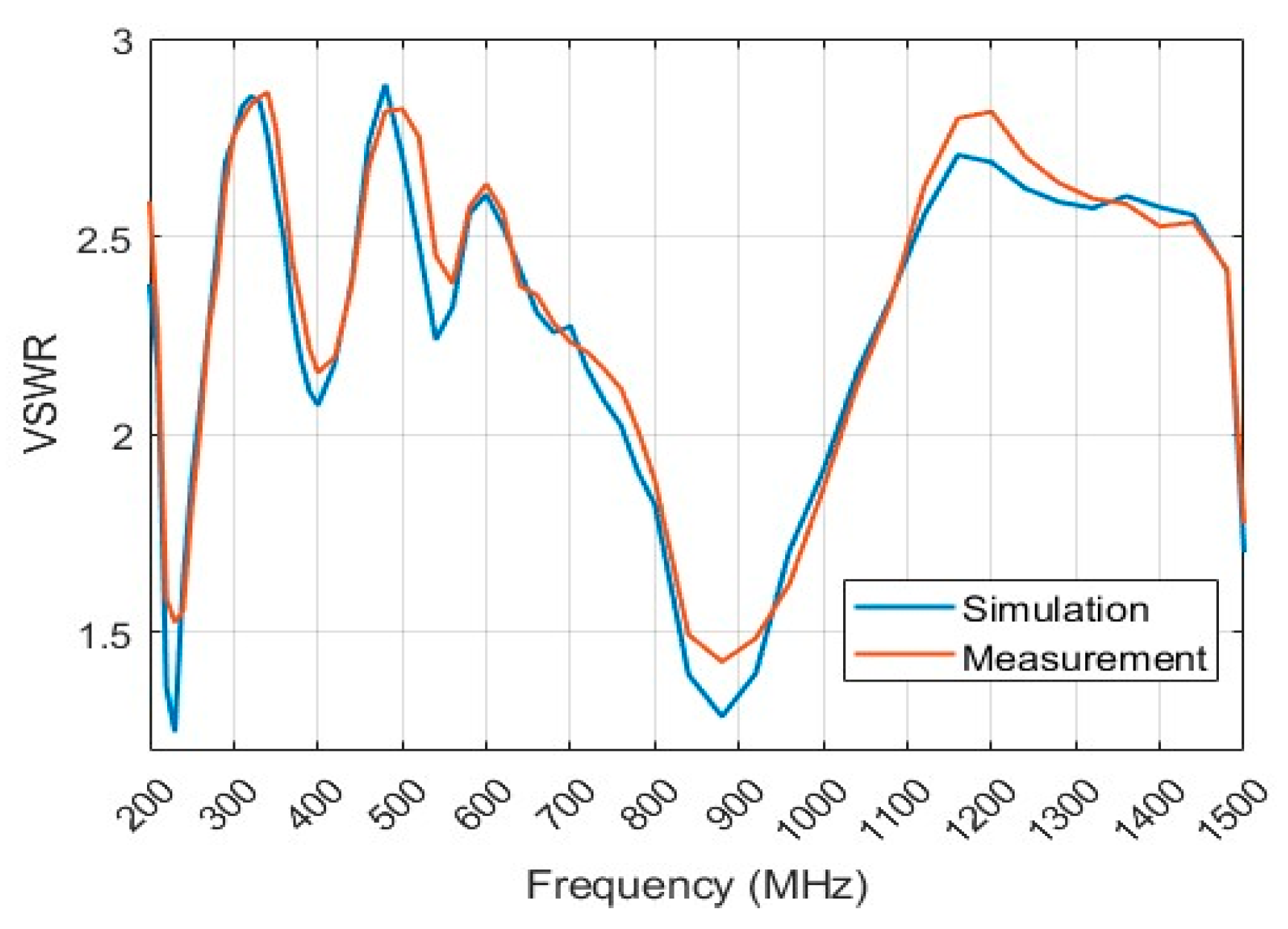
Figure 16.
The measured and simulated VSWRs.
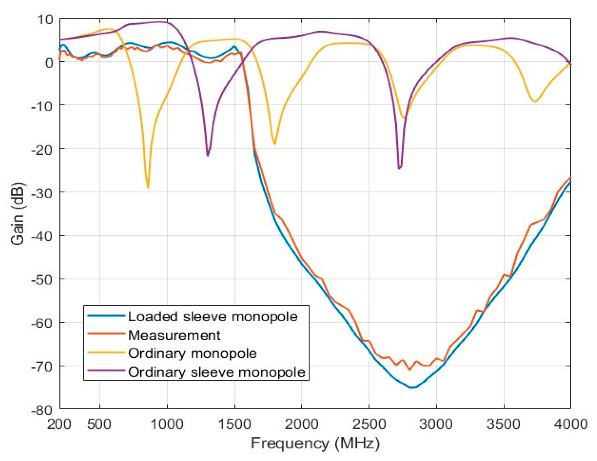

Table 1.
Parameter of optimized load of the lower monopole.
| Load Position (mm) | Resistance (ohm) | Inductance (nH) | Capacitance (pF) |
| 178 | 100 | 25 | 3 |
| 225 | 1600 | 8.5 | 1 |
| 265 | 200 | 10 | 1.2 |
Disclaimer/Publisher’s Note: The statements, opinions and data contained in all publications are solely those of the individual author(s) and contributor(s) and not of MDPI and/or the editor(s). MDPI and/or the editor(s) disclaim responsibility for any injury to people or property resulting from any ideas, methods, instructions or products referred to in the content. |
© 2025 by the authors. Licensee MDPI, Basel, Switzerland. This article is an open access article distributed under the terms and conditions of the Creative Commons Attribution (CC BY) license (https://creativecommons.org/licenses/by/4.0/).
Copyright: This open access article is published under a Creative Commons CC BY 4.0 license, which permit the free download, distribution, and reuse, provided that the author and preprint are cited in any reuse.


