
Submitted:
02 May 2025
Posted:
06 May 2025
You are already at the latest version
Abstract
The Ravne 3 tunnel complex, situated in the central region of Bosnia-Herzegovina, represents a recently excavated subterranean feature of potential archaeological and environmental significance. This study presents an integrated stratigraphic, artifact-based, and environmental analysis of the Ravne 3 tunnels. Stratigraphic profiles and multi-period artifact assemblages suggest episodic human activity spanning from the Roman era to the Late Middle Ages. Radiocarbon and U-Th dating of organic samples and speleothems provide a chronological framework, with calibrated dates ranging from the 4th century CE to approximately 5900 years BP. Environmental monitoring within the tunnel reveals elevated concentrations of negative ions, low electromagnetic radiation, and stable microclimatic parameters, contributing to a regenerative subterranean environment. The findings support the hypothesis that Ravne 3 is part of a larger, historically utilized tunnel system in the Visoko valley, with implications for both heritage management and bio-environmental science.
Keywords:
Ravne 3 tunnel
; archaeological stratigraphy
; radiocarbon dating
; negative ions
; underground environments
; Visoko
; Bosnia-Herzegovina
; subterranean architecture
; environmental monitoring
; speleothem analysis
1. Introduction
The Ravne 3 Tunnel Complex, located in the Visoko Valley of central Bosnia-Herzegovina, was discovered in July 2018 and has been under continuous excavation and multidisciplinary investigation by the Archaeological Park: BPS Foundation through 2024. The site represents a previously undocumented subterranean structure, distinct in stratigraphy and construction from nearby Ravne tunnels, yet positioned at the same latitude and within a spatial context suggesting architectural coherence with the broader tunnel network of the valley.
Excavation campaigns between 2018 and 2024 yielded stratigraphic sections with clearly defined depositional layers, containing cultural material such as ceramics, metal tools, and architectural features including dry-stone wall segments (suhozidi). Stratigraphic context and artifact typology indicate episodic use and modification of the tunnels from antiquity through the medieval period of the central Balkan region. Ceramics recovered from Trench A302 and surrounding zones include fragments attributable to Roman-period tegula, terra sigillata, and coarse medieval wares, many of which exhibit typological and decorative characteristics consistent with domestic usage [1].
Chronological control has been established through radiometric methods. Radiocarbon dating conducted at the Kiev Radiocarbon Dating Laboratory returned calibrated dates as early as the 4th century CE, while Uranium-Thorium analysis of a stalagmite sample (S002) from the same stratigraphic unit yielded a corrected age of approximately 5,900 years before present, placing the initial sedimentation and tunnel formation in the late Neolithic or early Eneolithic period [2,3].
Geological and sedimentological investigations confirm that the tunnel is embedded in Miocene marls and interbedded sandstones, overlain by horizontally bedded Ravne conglomerate. A complete east-west geological cross-section (Figure 3) illustrates the relationship between overburden, tunnel cuts, and the host sediments. The Ravne 3 tunnels penetrate this matrix with near-horizontal bedding, which has aided in preserving interior features and allowing for stratigraphic continuity across multiple excavation sectors.
Geodetic mapping of the complex was conducted using Total Station (Topcon GTS 105N) and Trimble 5700 GPS receivers, coordinated by a certified survey agency based in Visoko (Survey Wizard). The tunnel’s internal passages were digitally modeled in AutoCAD and QGIS environments and integrated with LiDAR-based topography generated under contract by Airborne Technologies GmbH (Austria) in 2020 (Contract No. 01/2020, dated April 14, 2020) [4]. This spatial dataset has enabled precise georeferencing of the Ravne 3 entrance, galleries, and dry-stone blockages, as well as comparisons with adjacent complexes including Ravne 2 and Ravne 4 (Figure 1, Figure 2, Figure 3, Figure 4, Figure 5 and Figure 6).
Although additional scientific monitoring of the microclimate, ion concentrations, and magnetotelluric fields has been undertaken as part of broader site research [5,6,7], this article is focused solely on archaeological stratigraphy, geological context, artifact analysis, and dating results. Environmental data and energy-related findings are referenced where relevant but are presented as supporting context rather than interpretive framework.
This article represents the first peer-reviewed archaeological report dedicated specifically to the Ravne 3 Tunnel Complex. It aims to:
- Establish the site’s archaeological significance through stratified artifacts and associated features;
- Present stratigraphic profiles and material typology with radiometric corroboration;
- Situate the Ravne 3 complex within the broader spatial-geological framework of the Visoko Valley;
- Propose hypotheses regarding its function, chronology, and relation to adjacent tunnel systems.
The evidence presented herein supports the interpretation of Ravne 3 as a genuine subterranean archaeological site with multiperiod use, meriting continued scientific investigation within the frameworks of Balkan prehistory, Roman-era infrastructure, and early medieval subsurface construction traditions.
2. Legal and Institutional Framework
The Ravne 3 Tunnel Complex excavation and all associated scientific investigations have been conducted under full compliance with the legal and administrative framework governing archaeological research in Bosnia-Herzegovina. The lead institution responsible for all field operations, documentation, and reporting is the Archaeological Park: BPS Foundation, headquartered in Visoko.
The Foundation is formally registered as a research and cultural organization with the Ministry of Justice of Bosnia-Herzegovina, and is authorized to conduct archaeological, scientific, and cultural heritage protection activities throughout the territory of Bosnia-Herzegovina. This legal status enables the Foundation to initiate fieldwork, coordinate with domestic and international experts, and submit research results to relevant institutions.
Each year, fieldwork is carried out under annual archaeological permits issued by the Ministry of Culture and Sports of the Zenica-Doboj Canton. A prerequisite for permit issuance is the submission of a signed collaboration contract with the Zavičajni Muzej Visoko (Local Heritage Museum Visoko), which serves as the local cultural custodian and institutional partner in the municipality.
In addition to cantonal approval, all research activities and site interventions are subject to review and approval by the Federal Institute for the Protection of Monuments, located in Sarajevo. The Institute’s oversight ensures that all excavation, conservation, and heritage-related interventions are performed in accordance with the Law on the Protection and Use of Cultural, Historical and Natural Heritage (Zakon o zaštiti i korištenju kulturno-historijskog i prirodnog naslijeđa, Official Gazette of FBiH No. 33/02).
At the close of each field season, the Foundation submits a comprehensive annual archaeological report, detailing excavation progress, documentation, artifact inventories, radiometric analyses, and any conservation activities undertaken. Only after formal acceptance of this report by both the Ministry and the Institute can the Foundation receive renewal of excavation rights for the following year.
For the Ravne 3 Tunnel Complex specifically, this procedure has been followed continuously from July 2018 through the 2024 season. No unauthorized excavations have been undertaken, and all cultural materials recovered from the site have been catalogued, stored, and analyzed in coordination with licensed archaeologists and museum professionals. The Foundation’s team has included certified field archaeologists (MA Amna Agić, Amar Tufo), geodesists (Eng. Tarik Sokolović, Eng. Tarik Harbaš), geologists (Mejra Kozlo, Richard Hoyle), and a technical support team working under professional and legal supervision.
This rigorous legal and institutional process ensures that all data presented in this article are based on research performed with full authorization, transparency, and accountability to cultural heritage authorities in Bosnia-Herzegovina.
3. Geological and Geodesic Context
The Ravne 3 Tunnel Complex is located in the geomorphologically diverse Visoko Basin, within the broader Zenica–Sarajevo Neogene depression of central Bosnia. The tunnel is embedded within the Ravne Conglomerate Formation, a horizontally bedded Quaternary fluvial sequence composed of rounded cobbles, gravels, and coarse sands, resting unconformably above Miocene lacustrine sediments consisting predominantly of marl and sandy-clay interbeds.
A complete east-west geological cross-section of the site (Figure 3) reveals that the Ravne conglomerates are structurally stable and lie nearly horizontal, while the underlying Miocene units dip north-northwest, producing an angular unconformity between the two sequences. This sedimentological relationship is critical for understanding the long-term preservation of tunnel voids and the stability of tunnel ceilings observed during excavation. The natural bedding planes likely facilitated easier excavation and structural maintenance by past tunnel constructors.
Lithostratigraphic mapping conducted by field geologist Richard Hoyle confirms that the tunnel cuts primarily into the conglomerate layer, but in some segments intersects the upper boundary of the marl, particularly in collapsed sections and cavity zones. Several cavities (designated C1–C4) exhibit stratigraphic profiles with clearly separated layers of compacted conglomerate ceiling, marl base, and fill material composed of angular fragments and unconsolidated sediment (Figure 9 and Figure 10).
Topographic and spatial mapping of the Ravne 3 tunnel system has been conducted using high-resolution geodetic and LiDAR techniques. The initial survey was carried out using Total Station (Topcon GTS 105N) and Trimble 5700 GPS receivers, with data acquisition and coordination by Eng. Tarik Harbaš of the Visoko-based licensed geodetic firm Survey Wizard. A second-stage refinement and horizontal mapping were completed by Eng. Tarik Sokolović, whose survey contributed to the digital reconstruction of both Ravne 3 and the surrounding tunnel systems (Ravne 1, Ravne 2, Ravne 4 and Ravne 6) using QGIS and AutoCAD environments (Figure 5 and Figure 6).
The LiDAR survey conducted by Airborne Technologies GmbH (Austria) in April 2020 (Contract No. 01/2020) provided a full-resolution orthophoto and surface model of the Visoko Valley, including elevation differentials and geospatial integration of known tunnel entrances. The processed data allowed for precise calculation of distances, orientations, and elevation differences between Ravne 3, Ravne entrance tunnels, and nearby features such as the Vratnica Tumulus and the Krtnica–Četnica ridge line. These LiDAR outputs (Figure 1 and Figure 2) confirmed that Ravne and Ravne 3 lie at nearly identical latitudes, separated laterally by approximately 200 meters, with no current evidence of a direct physical connection.
The digital terrain models also helped identify recurring features, such as the near-horizontal extension of tunnels and the consistent location of dry-stone wall structures along infill transitions and passage terminations. To date, five dry-stone blockages have been documented in Ravne 3 (Figure 33), supporting the interpretation that segments of the tunnel were intentionally sealed—a feature shared with Ravne and Ravne 4.
In summary, the geological and geodesic context of Ravne 3 establishes that the tunnels are cut into stable sedimentary substrates, exhibit stratigraphic integrity, and align spatially with adjacent subterranean structures in the Visoko Valley. The integration of field geology and high-precision survey technologies ensures that all subsequent archaeological interpretations are grounded in a reliable geological and spatial framework.
4. Stratigraphy and Archaeological Features
Excavation of the Ravne 3 Tunnel Complex has been conducted under controlled archaeological methodology between 2018 and 2024, revealing well-preserved stratified cultural layers and multiple architectural and anthropogenic features. A total of seven trenches and open profiles were documented, with the most complete stratigraphic record recovered from Trench A302 (Figure 32).
4.1. Stratigraphic Layers and Sediment Composition
The tunnel walls and trench profiles exhibit clear lithostratigraphic layering, typically composed of the following units:
- Upper fill layer: Loose, heterogeneous material including angular rock fragments, organic debris, and clayey-silt matrix. Often associated with intrusion or post-depositional collapse.
- Compact fill layer: Unconsolidated tunnel infill with embedded artifacts, particularly ceramics and charcoal fragments.
- Sediment interface: Fine-grained marl or mixed marl-silt contacts forming the base of many chambers and cavities.
- Ceiling boundary: Bedded conglomerate with visible clast alignment, usually undisturbed in stratified sectors.
Stratigraphic diagrams from Cavity C2 and C3 illustrate the transition between natural ceiling conglomerates, constructed fill, and void/cavity phases (Figure 9 and Figure 10). These sections also contain linear intrusions interpreted as vague passageways intentionally blocked using material similar to the surrounding matrix.
4.2. Ceramic Assemblage
Excavation of the non-blocked tunnel sections, particularly in Chambers R3-1 and R3-2, yielded a total of 3,132 ceramic sherds, documented in detail by field archaeologist MA Amna Agić (Figure 16). The ceramic assemblage includes:
- Late Roman period material, including one fragment of a Roman tegula tile with a Celtic knot motif (Figure 15) and a partially reconstructed terra sigillata vessel (Figure 17 and Figure 18).
- Medieval domestic pottery, characterized by handmade construction, coarse temper, thin-walled forms, and linear incised decoration (Figure 19, Figure 20, Figure 21 and Figure 22).
- Partially reconstructed vessels, including a 21 cm high utilitarian pot from central Bosnia's medieval phase (Figure 21).
The chronological interpretation is based on typological analogies with known ceramic sequences from the central Balkan region. A small number of older sherds exhibit traits suggestive of Neolithic or Eneolithic periods but await further typological and compositional analysis.
4.3. Metal Artifacts
The site produced a modest assemblage of metal objects, with most pieces highly corroded due to moisture and soil chemistry. Notable finds include:
- An iron hedge bill or sickle-like implement, 28.5 cm in length, likely used for agricultural purposes (Figure 12).
- Several hand-forged iron nails, each approximately 11–12 cm long (Figure 13).
- Bronze artifacts, including a small pendant with abstract motifs, tentatively dated to the Roman period (Figure 15), and corroded bronze coins of indeterminate type (Figure 14).
These artifacts were primarily recovered from the raised tunnel floor in R3-1 and are considered secondary depositions, though stratigraphic integrity was preserved in most cases.
4.4. Dry-Stone Wall Structures (Suhozidi)
To date, five dry-stone wall segments have been identified in Ravne 3 (Figure 33), composed of rounded river cobbles stacked without mortar. These walls often appear at the terminal ends of side passages and cavities, frequently sealing off otherwise accessible sections. Their method of construction, placement, and recurrence across the complex suggest intentional closure of certain tunnel routes, consistent with similar features found in Ravne and Ravne 4.
4.5. Charcoal and Burn Layers
In 2023, a deposit of charred organic material was recovered from the interface of a dry-stone wall, interpreted as a burn feature or improvised hearth. Radiocarbon dating conducted in 2024 by the TÜBİTAK Marmara Research Center in Turkey returned a calibrated result consistent with the 4th century CE, aligning this activity with late Roman-era presence in the valley (Figure 28).
5. Chronological Framework
The Ravne 3 Tunnel Complex has been dated using a combination of radiocarbon (14C) and Uranium-Thorium (U/Th) methods, applied to both organic and speleothem samples collected in stratified excavation contexts between 2018 and 2023. These independent dating methods provide a coherent multi-period temporal framework, ranging from the Neolithic to the Late Roman period, and support interpretations of long-term episodic use and tunnel modification.
5.1. Radiocarbon Dating (14C)
A total of seven organic samples were submitted for radiocarbon analysis to the Conventional Radiocarbon Dating Laboratory in Kiev, Ukraine, and the Radiocarbon Laboratory of the TÜBİTAK Marmara Research Center, Gebze, Turkey. The analyzed materials include charcoal fragments, burnt wood, and organic inclusions in stratified infill, recovered from test trenches and dry-stone wall junctions.
A calibrated age range for key samples is summarized in Table 1 (see Figure 27):
- Sample S001 (Layer C): 3880 ± 55 BP → ca. 2290 BCE
- Sample S001 (Layer A): 2540 ± 50 BP → ca. 590 BCE
- Sample S2-025: 10,625 ± 300 BP (likely reworked or non-contextual)
- Charred organic material at suhozid interface (TÜBİTAK, 2024): calibrated to the 4th century CE, based on AMS results and correspondence from Prof. Dr. Mehmet Ergin (Figure 28)
The stratigraphic coherence of these results is reflected in the sediment layering: deeper charcoal inclusions date to the Bronze Age, while material embedded in dry-stone closures corresponds with Late Roman occupation.
5.2. Uranium-Thorium (U/Th) Dating of Speleothems
To evaluate the minimum age of tunnel stability, a sample (S002/B5) of stalagmite S002 was extracted from Chamber R3-2 and submitted for U-Th analysis in collaboration between the Institute of Geological Sciences, Polish Academy of Sciences (Warsaw) and the Institute of Geology CAS (Prague).
- The basal carbonate layer of the stalagmite yielded a corrected U/Th age of 5.9 ± 0.3 ka BP, or approximately 3900 BCE (Figure 25).
- This date represents the onset of undisturbed calcite deposition, implying that the tunnel’s micro-environment remained stable for at least 5,900 years, and potentially that its initial excavation predates this period.
5.3. Stratigraphic Correlation and Interpretive Chronology
The integration of stratigraphy, typological ceramic sequences, and laboratory dating results supports the identification of the following chronological phases within Ravne 3:
- Phase I (pre-3900 BCE): Possible original tunnel excavation, predating stable speleothem formation
- Phase II (ca. 2500–2300 BCE): First evidence of infill or collapse, associated with deep organic deposits
- Phase III (600–400 BCE): Intermediate re-use or exposure, possibly linked to regional Bronze/Iron Age activity
- Phase IV (4th century CE): Presence of late Roman occupation, evidenced by charcoal layers and ceramic assemblage
- Phase V (Medieval period): Local re-entry and utilitarian use, confirmed by coarse pottery, tool finds, and secondary wall constructions
These temporal layers correspond with broader settlement patterns in the central Balkan region, suggesting Ravne 3 was not an isolated void but likely part of an extended subterranean tradition with both practical and strategic use over millennia.
6. Environmental and Energetic Measurements
In addition to its archaeological significance, the Ravne 3 Tunnel Complex presents a stable and highly unusual microclimatic environment. Since 2020, the Archaeological Park: BPS Foundation has conducted periodic environmental and energetic parameter monitoring at multiple tunnel locations using calibrated portable instruments. The focus of these measurements is to assess air quality, electromagnetic conditions, and ion concentration, particularly in comparison with external (surface-level) environments.
6.1. Methodology
Environmental data were collected using the following instruments:
- Air ion counter (for negative and positive ion concentrations, ions/cm³)
- Nuclear radiation dosimeter (μSv/h)
- Electromagnetic radiation meter (mW/cm², 50 Hz–2.5 GHz range)
- Multi-environmental sensor for temperature (°C), humidity (%), and oxygen (%)
The measurements were performed in February 2024 by environmental researcher Evelina Čehajić, who documented five measurement points from the entrance to inner chambers (Figure 30). A supplementary graphical representation of ion and EM levels was also produced and archived (Figure 31).
6.2. Results
Environmental readings from Ravne 3 indicate:
- Consistent air temperature at 11.4°C and relative humidity of 75% in all interior locations
- Stable oxygen levels at 20.9% throughout the tunnel
- Negative ion concentrations ranging from 6,000 to 8,500 ions/cm³ within the tunnel, compared to only 200 ions/cm³ at the outside control location
- Positive ion levels of 6,500–7,000 ions/cm³ underground, versus 50 ions/cm³ outside
- Electromagnetic radiation: undetectable in all tunnel sectors (0.00 mW/cm²)
- Nuclear radiation: 0.09–0.11 μSv/h (well below natural background thresholds)
These results suggest a consistently low-radiation, EM-free, and ion-rich underground environment.
6.3. Comparative Interpretation
Elevated negative ion concentrations are typically associated with natural locations of high atmospheric purity, such as waterfalls, mountain ridges, or forested areas. Negative air ions (NAIs) are electrically charged particles that arise from the interaction of air, moisture, and mineral surfaces. Scientific studies have shown their capacity to suppress airborne pollutants and support favorable electro-biophysical conditions in closed environments [1,2].
Ravne 3’s combination of high NAI levels, stable temperature and oxygen, and absence of electromagnetic pollution creates a rare environmental setting. Similar concentrations have been documented only in isolated subterranean zones such as deep karst caves, ion therapy chambers, and engineered underground laboratories [3].
While the potential physiological or regenerative effects of such environments remain the subject of parallel studies [4,5,6], this article highlights these measurements for their scientific documentation value and relevance to the preservation of the archaeological site itself. Stable environmental conditions are beneficial for the conservation of organic and ceramic materials and support long-term archaeological and monitoring work within the site.
7. Conclusions
The Ravne 3 Tunnel Complex represents a significant archaeological discovery within the Visoko Valley of central Bosnia-Herzegovina. Since its discovery in July 2018, systematic excavation, mapping, and scientific documentation have revealed a stratified, architecturally coherent subterranean feature embedded within a well-understood geological matrix. The structure is distinct yet directionally aligned with the broader Ravne Tunnel system, raising important questions about regional subterranean construction practices.
Archaeological excavations have identified multiperiod occupation layers, including Late Roman, medieval, and potentially prehistoric phases, supported by over 3,000 ceramic fragments, metallic artifacts, and architectural elements such as dry-stone wall segments. Radiocarbon dating of organic materials, paired with U-Th analysis of speleothems, provides a robust chronological framework spanning from c. 5900 BP to the 4th century CE, confirming the site’s relevance across multiple cultural phases of the central Balkan region.
Geological and stratigraphic analysis confirms that the tunnel was excavated into structurally stable Quaternary conglomerates, overlying Miocene marls, and preserved in part due to natural bedding conditions. Geodetic and LiDAR mapping, carried out by licensed professionals, has demonstrated the tunnel’s horizontal orientation and its spatial alignment with other known complexes. The documentation of five dry-stone wall features further supports interpretations of intentional tunnel modification or closure during certain occupation phases.
Environmental monitoring within the tunnel has confirmed a stable subterranean microclimate, marked by elevated negative ion concentrations, minimal electromagnetic interference, and low background radiation. While these parameters are not the primary focus of this archaeological report, they contribute to the preservation of the site and support the long-term viability of in situ research.
Taken together, the stratigraphy, material culture, dating results, and environmental conditions establish Ravne 3 as a genuine and previously unknown archaeological complex, meriting continued research within the frameworks of archaeology, geology, geodesy, and environmental science. The site contributes to our understanding of subterranean infrastructure in the central Balkan historical landscape, and provides a unique opportunity for multidisciplinary collaboration moving forward.
List of Figures
- Figure 1. Orthophoto of the Visoko Valley generated via LiDAR technology (Airborne Technologies GmbH, Austria). The Ravne Tunnels are located in the upper left corner.
- Figure 2. LiDAR-rendered relief of the northwest-trending Ravne Valley with marked entrances to the Ravne and Ravne 3 tunnels; distance between them is approximately 200 meters.
- Figure 3. East–west geological cross-section of the Ravne Valley showing horizontally bedded Ravne Conglomerate overlying Miocene marl with an angular unconformity.Figure 4. Known extent of the Ravne Tunnel Complex, estimated at 214,430 m² with a perimeter over 1.8 km.
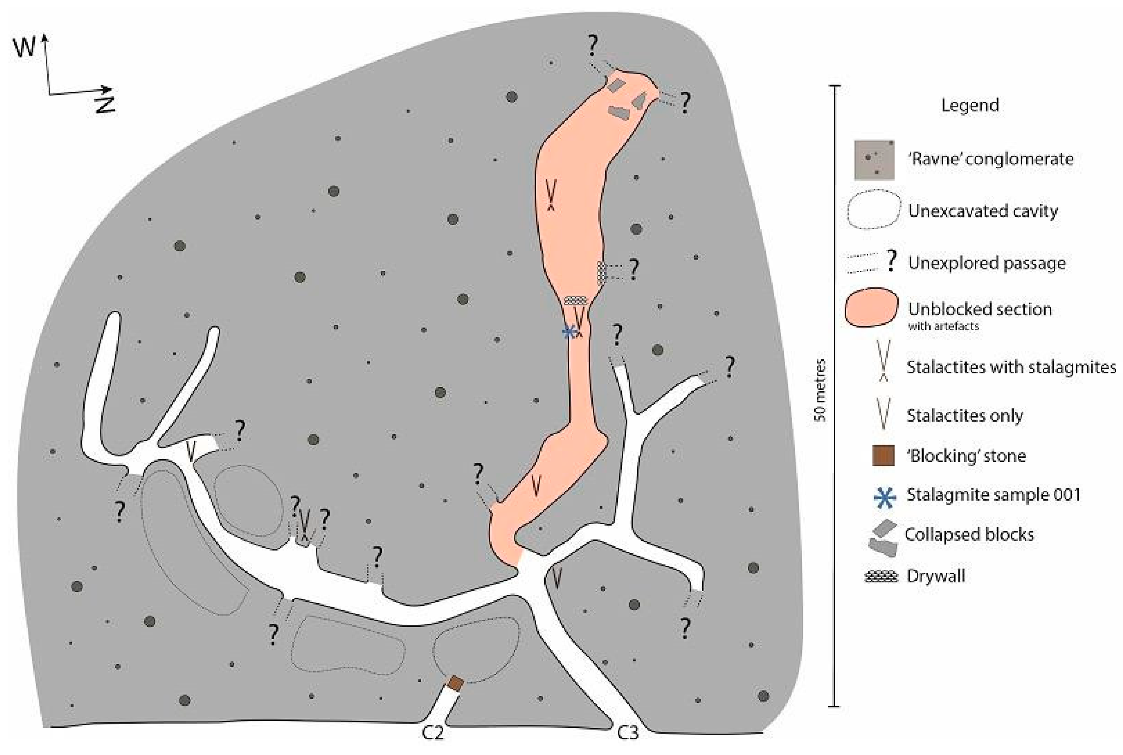
- Figure 5. Mapped Ravne 3 Tunnel passages showing explored and blocked sections; headings and terminations indicated.
- Figure 6. Comparative map showing Ravne 3's position relative to the broader tunnel system; geodetic data by Eng. Tarik Harbaš and Eng. Tarik Sokolović.
- Figure 7. Stratigraphic contact between compact conglomerate ceiling, marl floor, and unconsolidated infill material within Ravne 3.
- Figure 8. Cavity C3 with a placed blocking stone embedded in the upper fill, interpreted as passage sealing.
- Figure 9. Schematic stratigraphy of Cavity C2 showing cavity floor, walls, marl base, and infill layers.
- Figure 10. Photo documentation of fill composition in Ravne 3 cavities showing root intrusions and rock debris.
- Figure 11. Archaeological test trench (1×1 m) in elevated floor zone of Ravne 3; site of most artifact recovery (Photo: Amna Agić).
- Figure 12. Corroded iron hedge bill tool (28.5 cm), with preserved wooden handle traces; dated to the Roman period.
- Figure 13. Corroded iron blade and forged nails (11–12 cm), interpreted as utilitarian tools; from medieval layers.
- Figure 14. Corroded bronze coins, diameter 1–1.5 cm; recovered from compact fill in Chamber R3-1.
- Figure 15. Bronze pendant with abstract Celtic motif; possibly Roman in date; diameter 1.5 cm.
- Figure 16. Stratified ceramic fragments from R3-1 and R3-2; includes terra sigillata and medieval coarse ware.
- Figure 17. Roman terra sigillata luxury bowl, diameter 11 cm; partially reconstructed.
- Figure 18. Further reconstruction of the same terra sigillata vessel (11 cm diameter).
- Figure 19. Medieval pottery sherds with incised decoration; length 4–5 cm.
- Figure 20. Rim fragments of medieval domestic pot; grainy surface and low-quality paste.
- Figure 21. Partially reconstructed medieval pot; 13 cm diameter, 21 cm height.
- Figure 22. Ceramic fragments showing vessel neck (left) and reconstructed base (right); medieval period.
- Figure 23. Stalactites and stalagmites in Chamber R3-2 (Photo: Dr. Sam Osmanagich).
- Figure 24. Sampled stalagmite (S002) marked for U-Th dating; image of cross-section.
- Figure 25. U-series dating report for S002/B5 conducted by the Institute of Geology CAS and Polish Academy of Sciences.
- Figure 26. Profile section of test trench A302 showing stratified layers and clay horizon.
- Figure 27. Table of radiocarbon dating results from Kiev Laboratory, showing dates from ca. 2600 BCE to Late Antiquity.
- Figure 28. TÜBİTAK Marmara report confirming calibrated 4th-century CE date for charred material found at dry-stone wall.
- Figure 29. Magnetotelluric and audio-MT measurement summary from Ravne 3; data collected by Goran Marjanović in 2019.
- Figure 30. Environmental data from February 2024 (E. Čehajić): temperature, humidity, ion concentrations, EM and radiation levels.
- Figure 31. Graphical display of measured energetic values within Ravne 3 by Evelina Čehajić.
- Figure 32. Stratigraphic layers in Trench A302; internal documentation, Archaeological Park: BPS Foundation.
- Figure 33. Dry-stone wall segment (one of five) discovered in Ravne 3; interpreted as intentional tunnel blockage.
Author Contributions
Dr Sam Osmanagich designed and directed the archaeological fieldwork, coordinated geological and geodetic teams, conducted archival and comparative analysis, and authored the manuscript.
Funding
This research was funded by the Archaeological Park: BPS Foundation, Visoko, Bosnia-Herzegovina.
Data Availability
All excavation logs, stratigraphic records, environmental measurements, and dating reports are archived with the Archaeological Park: BPS Foundation and are available upon reasonable request.
Acknowledgements
The author acknowledges the contributions of field geologist Richard Hoyle, who served as the lead geological expert on-site, and archaeologist MA Amna Agić, the lead field archaeologist coordinating excavation strategy and artifact documentation. Gratitude is extended to fellow geologist Mejra Kozlo, archaeologist Amar Tufo, geodesists Eng. Tarik Sokolović and Eng. Tarik Harbaš (Survey Wizard), volunteer coordinator Marie-Sophie Gristi, and environmental technician Evelina Čehajić. Special thanks go to the Foundation’s on-site staff, led by supervisor Mustafa Bajić, for their dedicated daily field operations. Acknowledgement is also given to the Austrian LiDAR team from Airborne Technologies GmbH for their topographic and spatial data acquisition, telecommunications engineer Goran Marjanović for his magnetotelluric analysis, and both the Radiocarbon Laboratory in Kiev and the TÜBİTAK Marmara Research Center in Turkey for their analytical support.
Conflict of Interest
The author declares no conflict of interest.
Figures
Figure 1.
LiDAR-based topographic map of the Visoko Valley, Bosnia-Herzegovina, showing the entrance area of the Ravne Tunnel Labyrinth and its surrounding terrain. The digital elevation model highlights the broader geographic context of the Ravne Tunnel Complex (upper left), including surrounding hills, valleys, and the Fojnica River. Key geographic landmarks are labeled to assist spatial interpretation. This high-resolution terrain model was generated as part of a contracted aerial survey organized by the Archaeological Park: BPS Foundation. LiDAR survey and data processing conducted by Airborne Technologies GmbH (Austria) under contract with the Archaeological Park: BPS Foundation.
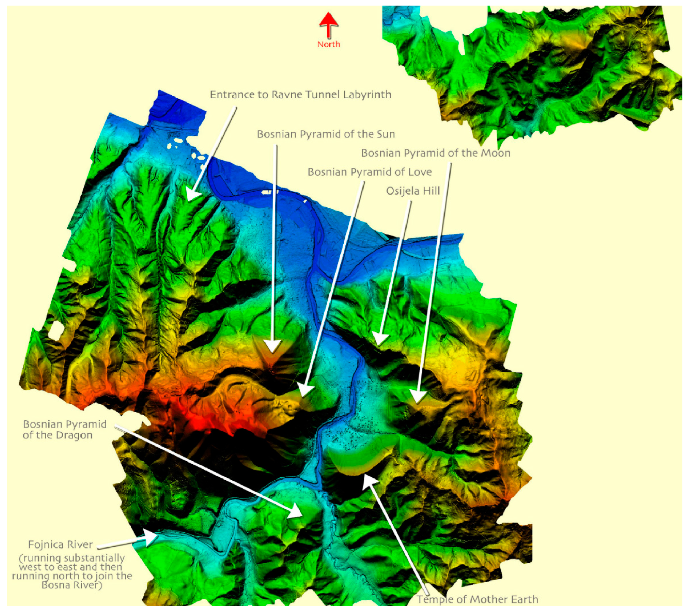
LiDAR Survey and Equipment Description
In order to produce a high-precision topographic model of the Visoko Valley and determine the natural and anthropogenic context of the Ravne Tunnel Complex, the Archaeological Park: BPS Foundation commissioned the Austrian firm Airborne Technologies GmbH to carry out a LiDAR survey of the entire region.
The engagement was formalized under Contract No. 04-23/2015, signed on March 12, 2015, with airborne data acquisition performed between April 4 and April 6, 2015, under favorable atmospheric and visibility conditions. The final processed data were delivered to the Foundation in May 2015.
The equipment configuration included:
- Laser Scanner: Riegl LMS-Q680i (wavelength 1550 nm, pulse rate up to 400,000 pulses/sec, range up to 2000 m, precision <20 mm)
- Navigation and Positioning: Trimble GNSS dual-frequency receivers with real-time kinematic (RTK) correction
- Inertial Measurement Unit (IMU): Applanix POS AV 510 for roll, pitch, and heading accuracy
- Aircraft Platform: Diamond Aircraft DA42 MPP (Multipurpose Platform), optimized for aerial surveys
Data post-processing included advanced filtering, point cloud classification, and digital elevation modeling (DEM) with a spatial resolution of approximately 25–50 cm. Hillshade rendering was used to enhance terrain features and provide a clear understanding of the Ravne Tunnel Complex’s position relative to surrounding geological and hydrological formations. These LiDAR data serve as a foundational reference for mapping, conservation planning, and archaeological interpretation within the Visoko basin.
Figure 2.
LiDAR terrain model showing the northwest-oriented valley with marked entrances to Ravne and Ravne 3 tunnels. This image highlights the spatial positioning of the main Ravne Tunnel entrance (right) and the Ravne 3 entrance (left), located approximately 200 meters apart on opposing slopes of a narrow valley oriented northwest to southeast. The LiDAR-based elevation model provides clear insight into the geomorphological layout of the area and supports further analysis of potential sub-valley tunnel continuity. Figure generated from LiDAR data acquired by Airborne Technologies GmbH (Austria) under contract to the Archaeological Park: BPS Foundation (Contract No. 04-23/2015). Prepared and annotated by field geologist Richard Hoyle. Originally published in: Hoyle, R. (2023). “Geoarcheological Summary Report.” In: Osmanagich, S., Hoyle, R., Agić, A., & Delibašić, H. (2023). Ravne 3 Tunnels (1st ed.). Archaeological Park: BPS Foundation, p. 26.
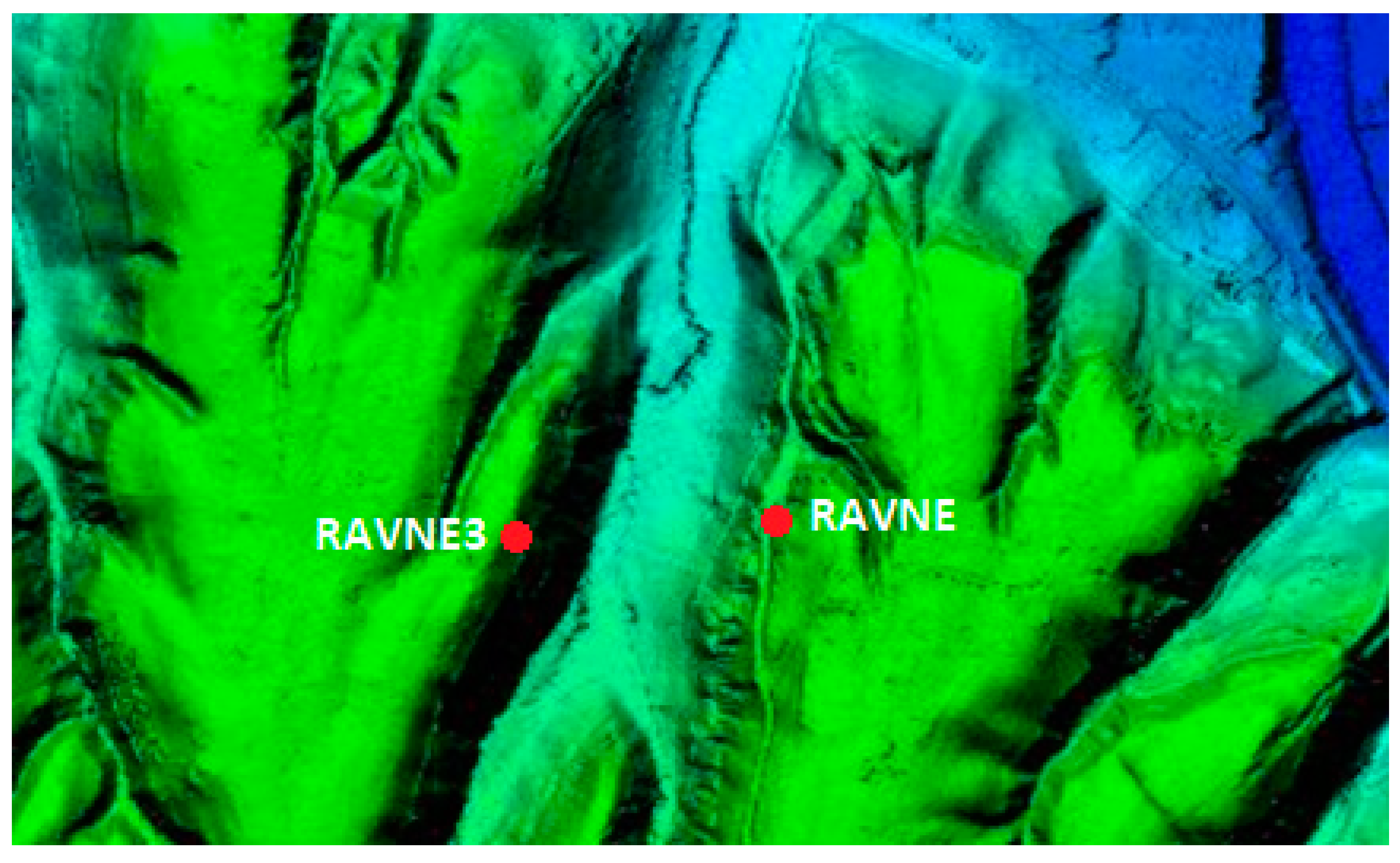
Figure 3.
Geological cross-section of the Ravne Valley showing relative positions of Ravne and Ravne 3 tunnel entrances and underlying formations. This east–west geological cross-section illustrates the stratigraphic relationship between the Ravne Conglomerate Formation and the older Miocene marl-sandstone sequence. The conglomerate layer appears approximately horizontal, while the underlying marls with interbedded sandstone dip northward and northwestward, forming an angular unconformity with the overlying unit. The vertical scale is exaggerated by a factor of 2. Tunnel entrances at Ravne and Ravne 3 are shown in cross-sectional profile, with Ravne 2 Park positioned in the central lowland area of the valley. Figure adapted from: Hoyle, R. (2018/2019). “Geoarchaeological Report.” In: Osmanagich, S., Hoyle, R., Agić, A., & Delibašić, H. (2023). Ravne 3 Tunnels (1st ed.). Archaeological Park: BPS Foundation, p. 31.
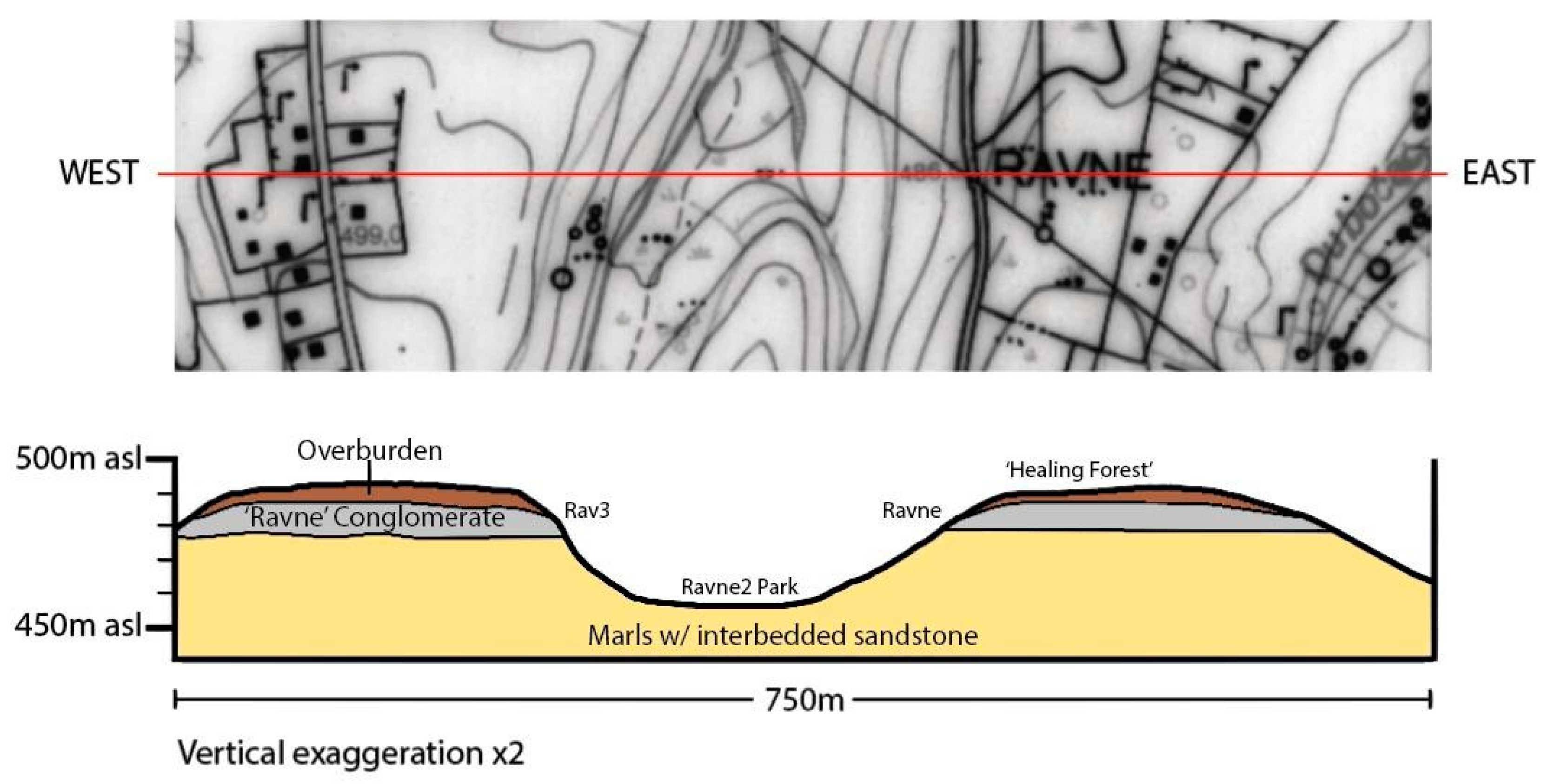
Figure 4.
Map showing the known extent of the Ravne Tunnels Complex, including tunnel sections Ravne, Ravne 2, Ravne 3, and Ravne 4. This composite map illustrates the currently explored tunnel segments of the Ravne Tunnel Complex, overlaid onto a satellite image of the Ravne 2 area. The dashed perimeter outlines the total known footprint of the complex, estimated at approximately 214,430 square meters, with a perimeter of just over 1.8 kilometers. The entrances to Ravne, Ravne 2, Ravne 3, Ravne 4, and the Orgon Chamber are marked. The park zones (Park Ravne 2 and Healing Forest) are highlighted in green, illustrating their integration with both archaeological and recreational features. Figure adapted from: Hoyle, R. (2018/2019). “Geoarchaeological Report.” In: Osmanagich, S., Hoyle, R., Agić, A., & Delibašić, H. (2023). Ravne 3 Tunnels (1st ed.). Archaeological Park: BPS Foundation, p. 104.
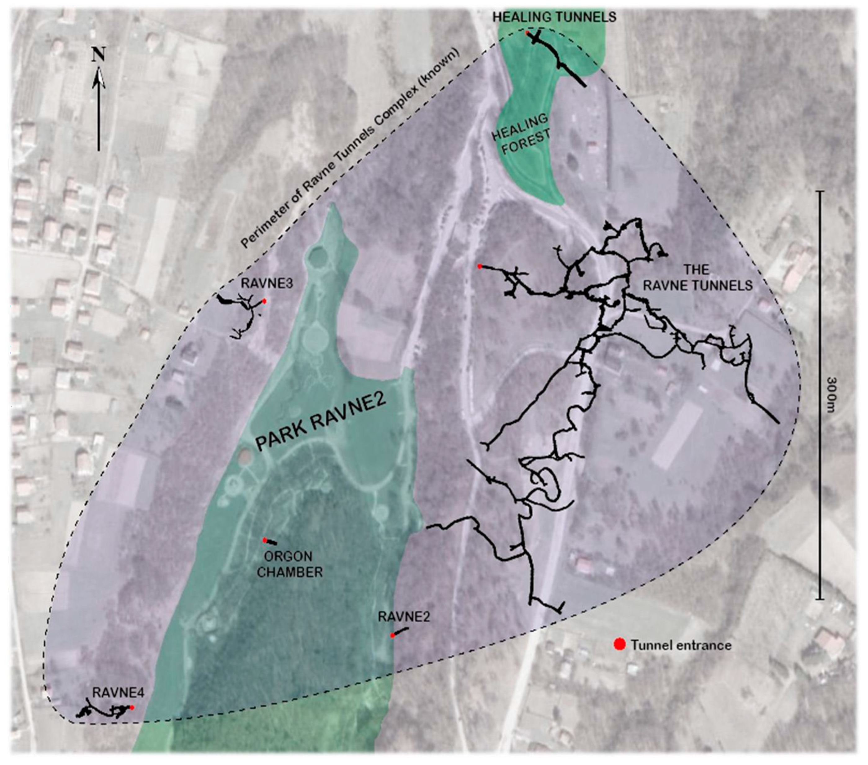
Figure 5.
Map showing explored sections of the Ravne 3 Tunnel network, with unexplored and blocked passages indicated. This plan view illustrates the current extent of mapped tunnels within the Ravne 3 Complex. Explored sections are shown in detail, while blocked or inaccessible passages are marked with approximate headings. The map highlights the intricate structure of the Ravne 3 tunnel system, including multiple side branches and narrowing conduits, and serves as a basis for ongoing archaeological and geological investigations.
RAVNE TUNNELS SURVEY; 2020
- Project Leader: Dr Sam Osmanagich, anthropologist
- Project Coordinator: Richard Hoyle, field geologist
- Technical: Eng. Tarik Harbaš, certified geodesist (Survey Wizard agency, Visoko)
- Field Archaeologist: Amna Agić
- Field Support: Mejra Kozlo, geologist
Survey Equipment Used:
- Total Station: Topcon GTS 105N
- GPS Receiver: Trimble 5700
- Tripod: TS tripod
- Prism: Nikon AK19 retroreflector prism
- Instruments: Suunto MC-2 compass/clinometer, FERM laser distance meter
The survey was conducted primarily using a Total Station in combination with a retroreflector prism. This instrument functions as an electronic theodolite with integrated distance measurement (EDM), capable of precisely measuring angles and distances through laser pulse reflection. Data were recorded and later processed using GIS and CAD software (QGIS, AutoCAD) to generate high-resolution 2D tunnel maps.
Figure prepared by Richard Hoyle. Originally published in: Hoyle, R. (2018/2019). “Geoarchaeological Report.” In: Osmanagich, S., Hoyle, R., Agić, A., & Delibašić, H. (2023). Ravne 3 Tunnels (1st ed.). Archaeological Park: BPS Foundation, pp. 102–103, 111.
Figure 6.
Survey map of the Ravne Tunnel Complex showing its extensive subterranean layout, with reference to the aligned position of Ravne 3. This geodetic map presents the explored and surveyed sections of the main Ravne Tunnel system, including side tunnels, dry-stone structures, water features, and key internal landmarks. The map demonstrates the scale, density, and structural organization of the complex. Although Ravne 3 is not included on this map, geodetic measurements confirm that the entrances to Ravne and Ravne 3 are situated at nearly the same latitude, separated laterally by approximately 200 meters across the valley. This precise horizontal alignment suggests that Ravne 3 may represent a western extension of the same ancient subterranean engineering project, supporting the hypothesis of a once-continuous tunnel network. Figure provided by Eng. Tarik Sokolović, certified geodesist from Visoko, based on official survey data collected in collaboration with the Archaeological Park: BPS Foundation (2024).
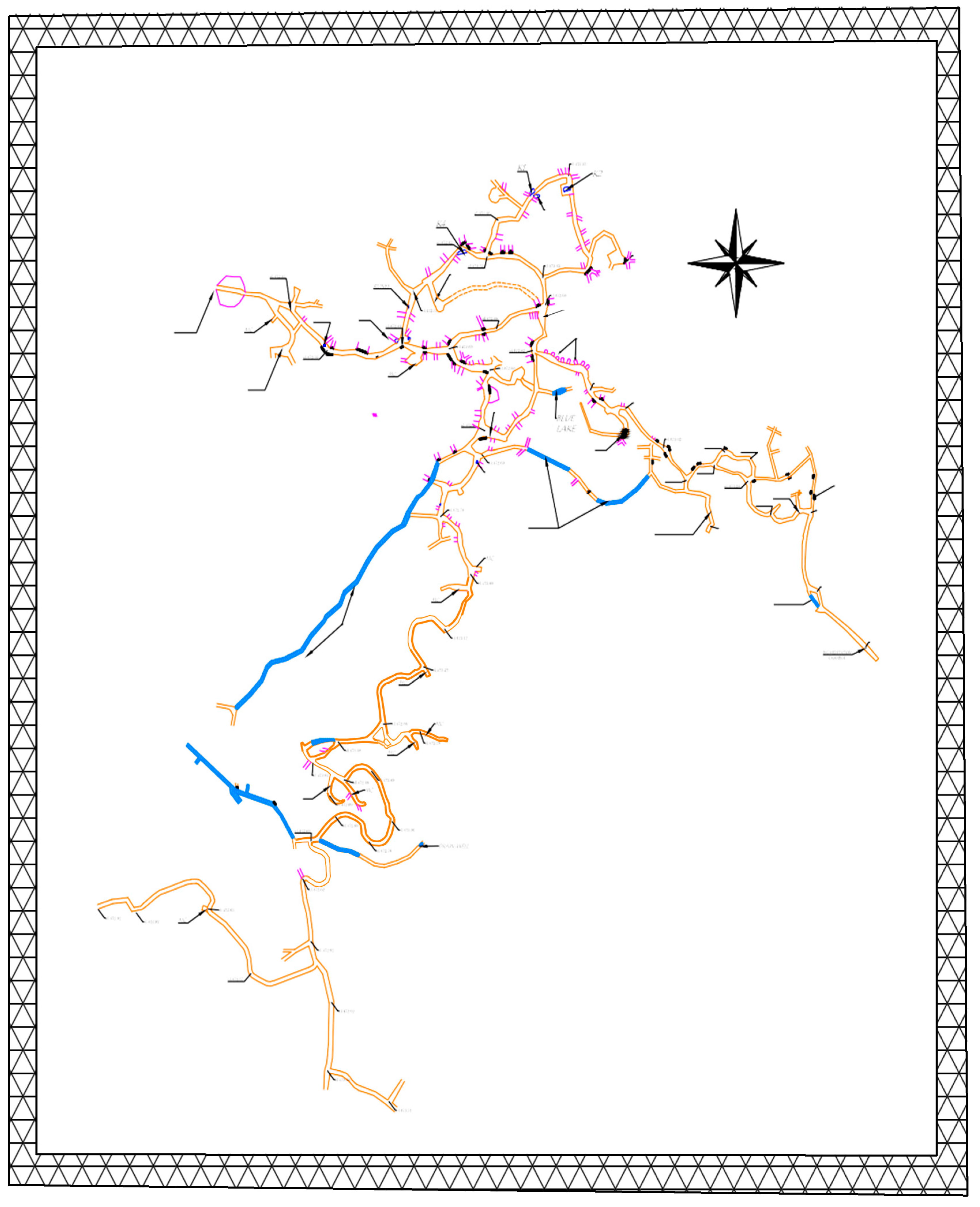
Figure 7.
Entrance zone of a rubble-filled passage in the Ravne 3 tunnel, located between solid conglomerate ceiling and marlstone floor. The image captures a transitional interface at the Ravne 3 tunnel entrance, where the ceiling is composed of lithified Ravne Conglomerate, the floor consists of Miocene marl, and the side walls contain loosely compacted, unconsolidated fill material. This composition is consistent with other observed segments deeper in the tunnel system and highlights the layered and intentionally sealed nature of the passage. Root systems intruding from above and the partial exposure of geological boundaries provide visual confirmation of distinct strata. Source: Osmanagich, S., Hoyle, R., Agić, A., & Delibašić, H. (2023). Ravne 3 Tunnels (1st ed.). Archaeological Park: BPS Foundation, p. 39.
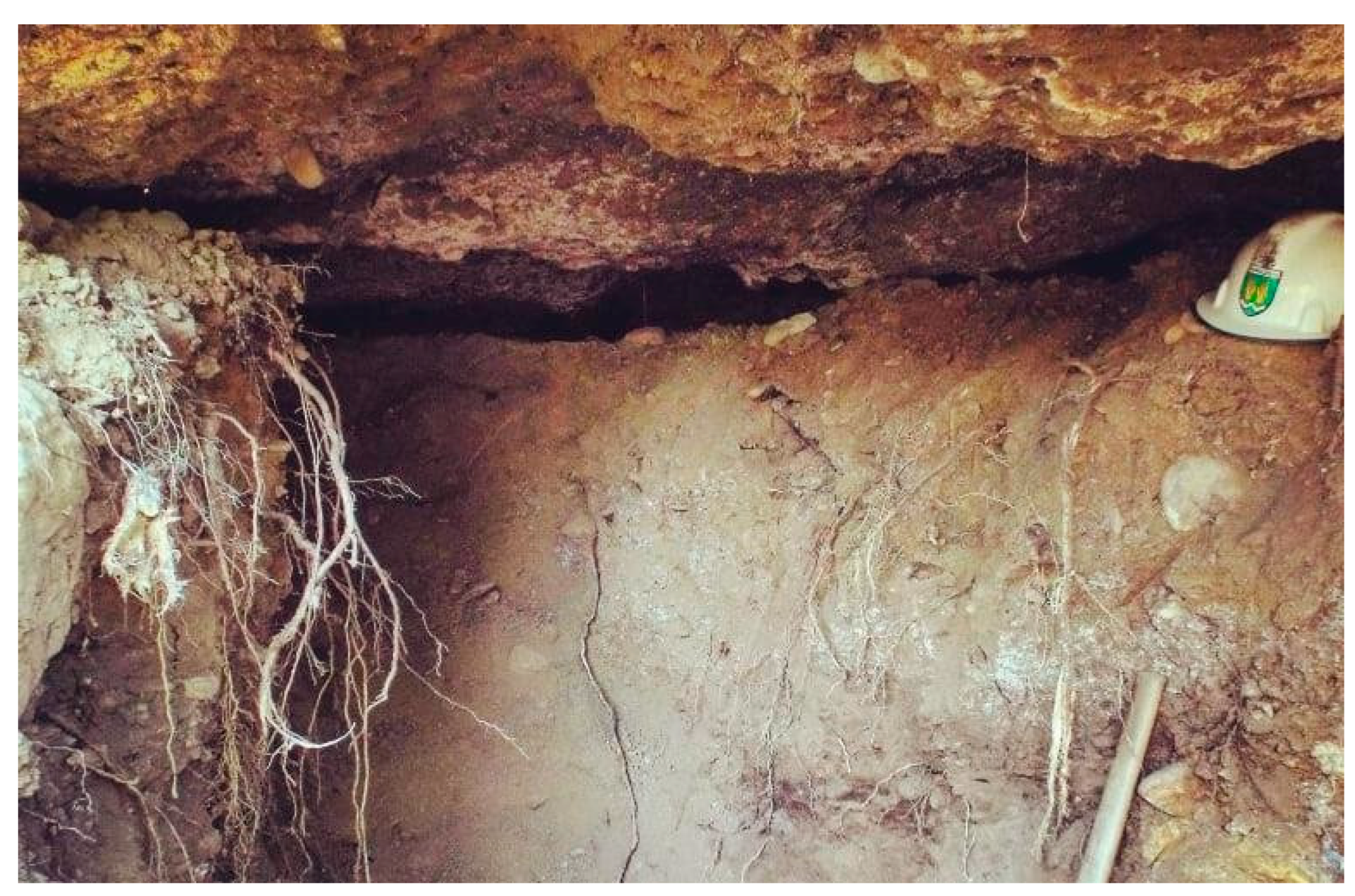
Figure 8.
Partially excavated cavity ‘C3’ in Ravne 3 showing a blocking stone embedded within upper fill material. This image captures the interior of cavity C3 during excavation, where a deliberately placed blocking stone appears lodged within the upper layers of unconsolidated fill material at a point where the void begins to enlarge. The stone’s positioning suggests a potential structural or sealing function, possibly intended to restrict access or manage air or water flow. The cavity ceiling is composed of compact Ravne Conglomerate, while the fill retains varied granularity. A 30 cm scale bar is provided for reference. Source: Osmanagich, S., Hoyle, R., Agić, A., & Delibašić, H. (2023). Ravne 3 Tunnels (1st ed.). Archaeological Park: BPS Foundation, p. 46.
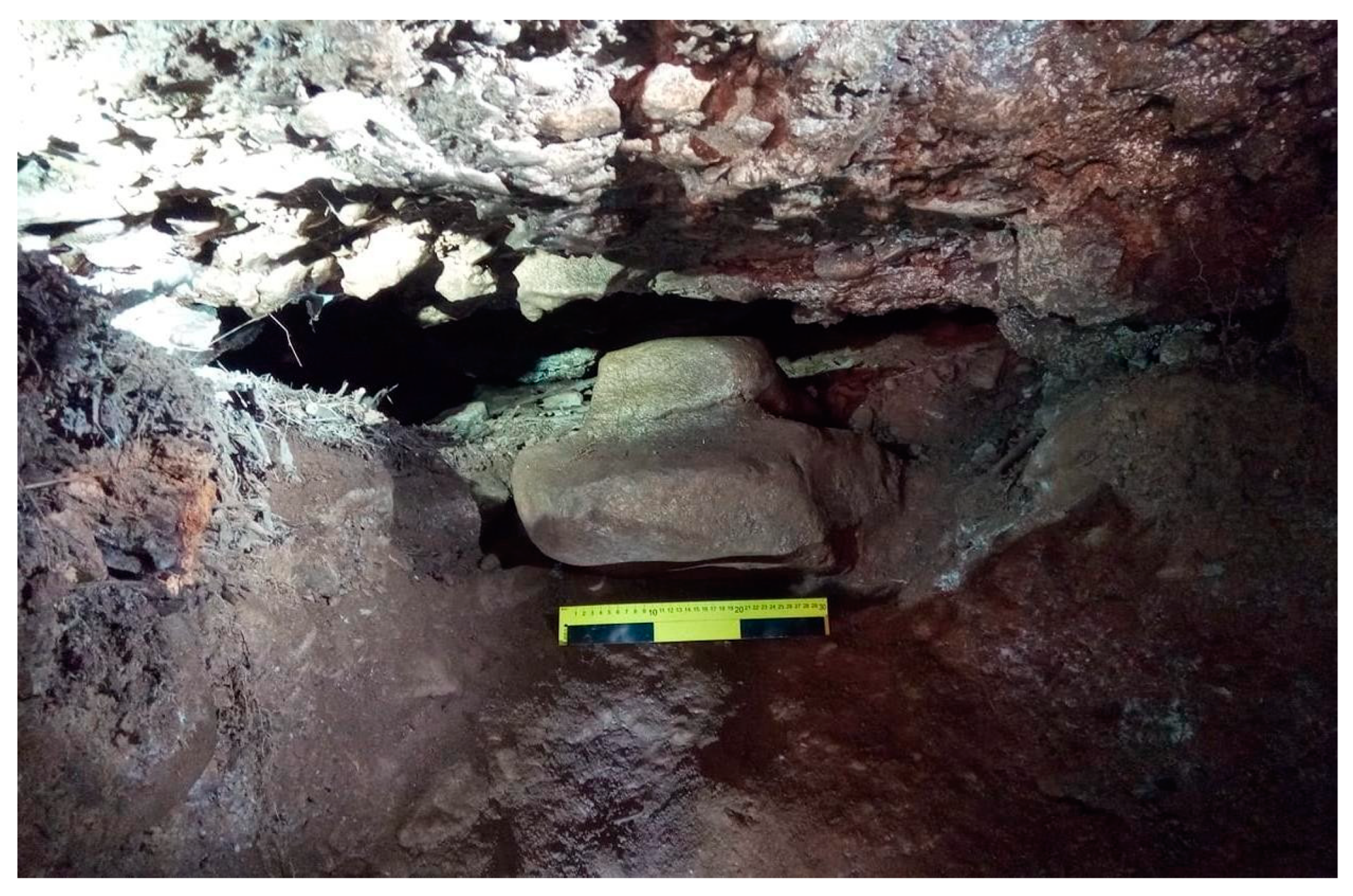
Figure 9.
Simplified stratigraphic diagram of cavity C2 in Ravne 3, showing distinct geological and structural features. This cross-sectional schematic illustrates the internal structure of cavity C2 as recorded during excavation at Ravne 3. The diagram identifies: 1. bedded conglomerate ceiling, 2. bedded marl base, 3. central cavity void, 4. geological boundary/cavity floor, 5. cavity walls, 6. unconsolidated cavity fill, 7. faint internal passageway through the fill, 8. looser fill within the passage, 9. surface root intrusion, and 10. ceiling debris (cave fall/litter). The total cavity height is approximately 1.8 meters. The diagram underscores the complexity of the fill material and the intentional-looking void patterns discovered within the sealed matrix. Source: Osmanagich, S., Hoyle, R., Agić, A., & Delibašić, H. (2023). Ravne 3 Tunnels (1st ed.). Archaeological Park: BPS Foundation, p. 40.
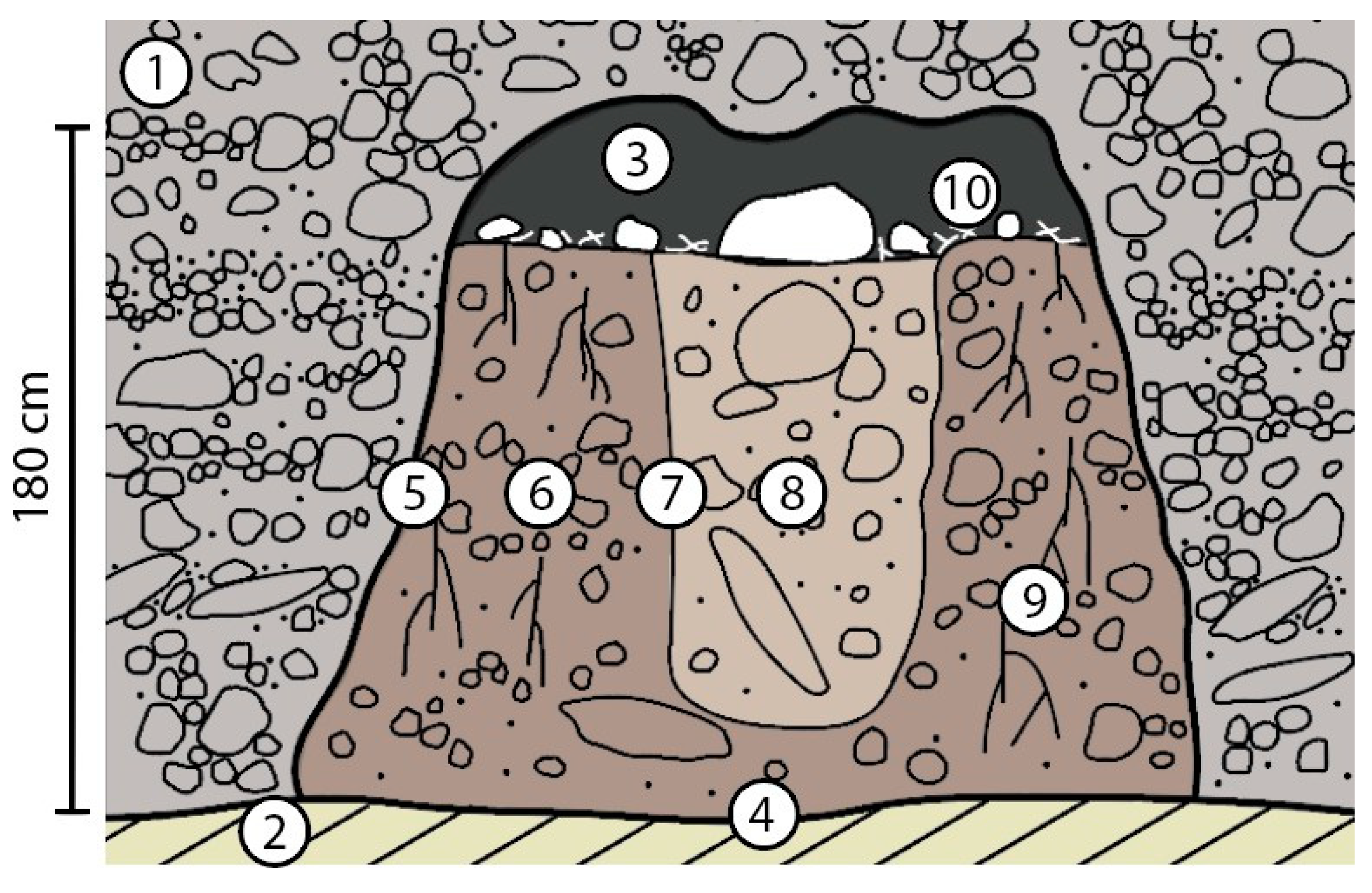
Figure 10.
Excavation profile showing a sharply defined fill pocket within solid conglomerate in the Ravne 3 tunnel. This image presents a clearly bounded area of filling material intruding into consolidated Ravne Conglomerate, as revealed during archaeological excavation. The irregular but well-defined boundary (dashed line) visually distinguishes the softer, differently textured fill from the surrounding lithified matrix. This stratigraphic contrast suggests a secondary infill episode and supports interpretations of intentional passage sealing or later collapse infill. The measuring rod provides an approximate scale of 1 meter (vertical). Source: Osmanagich, S., Hoyle, R., Agić, A., & Delibašić, H. (2023). Ravne 3 Tunnels (1st ed.). Archaeological Park: BPS Foundation, p. 41.
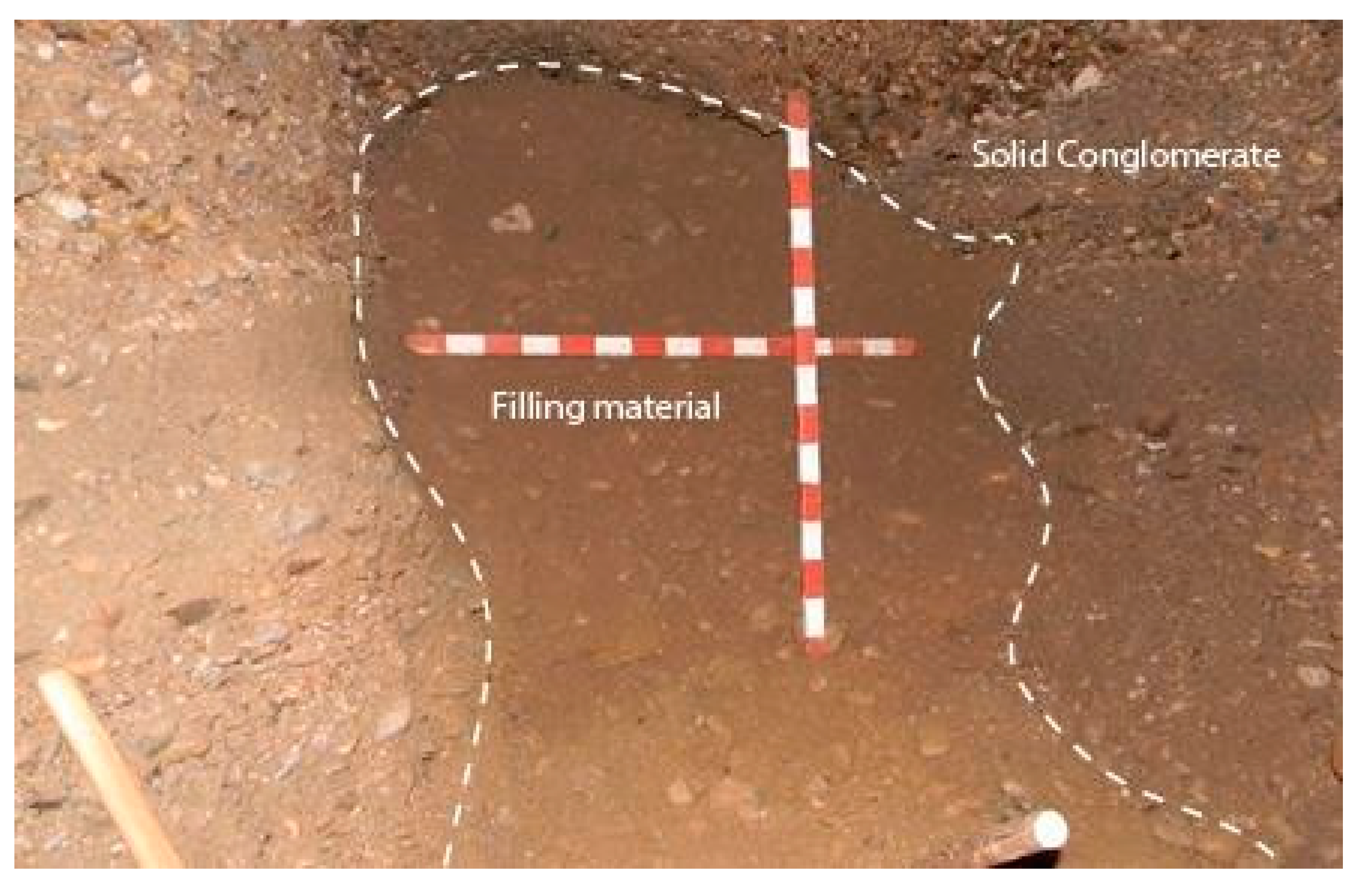
Figure 11.
Excavation of a 1 × 1 meter archaeological test trench within the elevated floor of the Ravne 3 tunnel. This photo documents active excavation work within a square trench measuring 1 × 1 m, set into a slightly raised area of the tunnel floor. The majority of archaeological finds from the Ravne 3 site were recovered within this elevated sedimentary zone, suggesting it may have functioned as a deposit area for cultural material or as a preserved occupation surface. Standard archaeological methods were applied, with stratigraphic layers carefully removed and screened. Photo by Amna Agić, field archaeologist. Source: Osmanagich, S., Hoyle, R., Agić, A., & Delibašić, H. (2023). Ravne 3 Tunnels (1st ed.). Archaeological Park: BPS Foundation, p. 58.
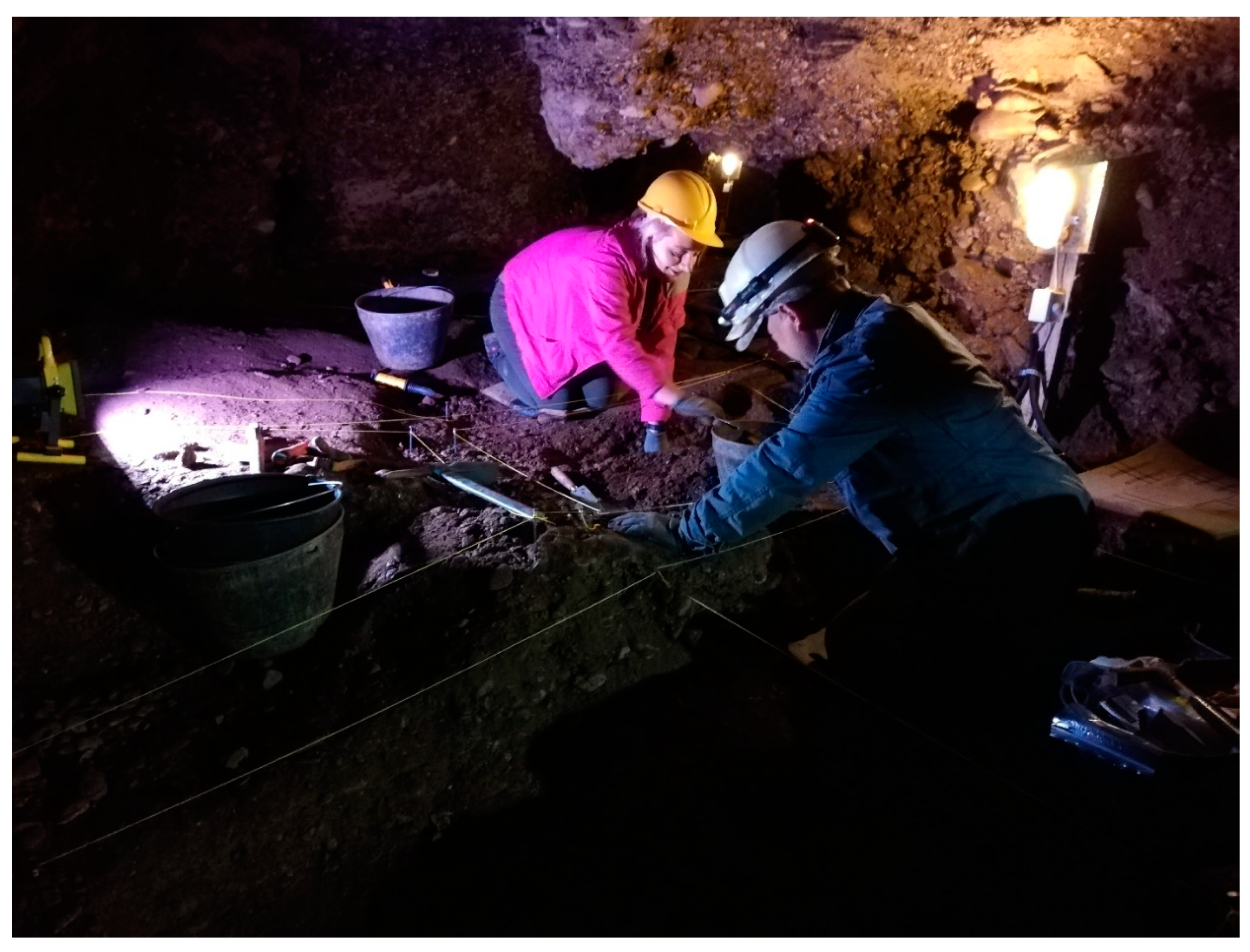
Figure 12.
Iron hedge bill (hooked blade tool) discovered in Ravne 3, tentatively dated to Roman period. This corroded iron tool, measuring 28.5 cm in length, belongs to the category of hooked agricultural implements, commonly referred to as hedge bills or pruning hooks. These tools are related to sickles (falces) and were traditionally used for cutting shrubs, vines, reeds, branches, and harvesting fruit. The object retains wooden residue embedded in the handle, indicating composite construction. Based on typological analogies with similar artifacts recovered in Bosnia and Herzegovina, the tool is preliminarily attributed to the Roman period. Source: Osmanagich, S., Hoyle, R., Agić, A., & Delibašić, H. (2023). Ravne 3 Tunnels (1st ed.). Archaeological Park: BPS Foundation, pp. 165–166.
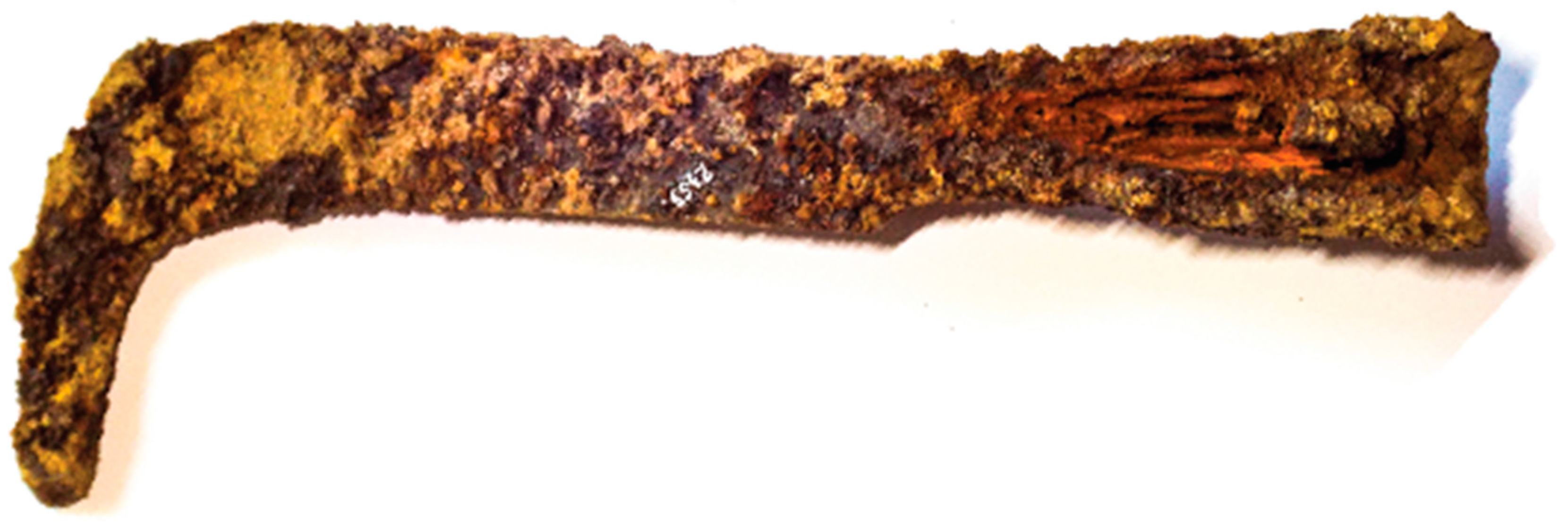
Figure 13.
Corroded iron artifacts from Ravne 3: medieval cutting blade and hand-forged nails. This image presents a small selection of metallic objects recovered from the open section of the Ravne 3 tunnel system. Due to the high moisture content and oxidizing conditions present within the raised floor layers, most ferrous artifacts were too deteriorated to permit identification. However, a few larger items with clearly distinguishable shapes were preserved. These include a cutting blade (length approx. 28.5 cm) and two hand-forged iron nails (11–12 cm in length). Based on typological characteristics and analogies from regional contexts, these objects are dated to the medieval period. In contrast to the corroded iron, some bronze artifacts recovered from the site exhibited significantly better preservation. Source: Osmanagich, S., Hoyle, R., Agić, A., & Delibašić, H. (2023). Ravne 3 Tunnels (1st ed.). Archaeological Park: BPS Foundation, p. 70.
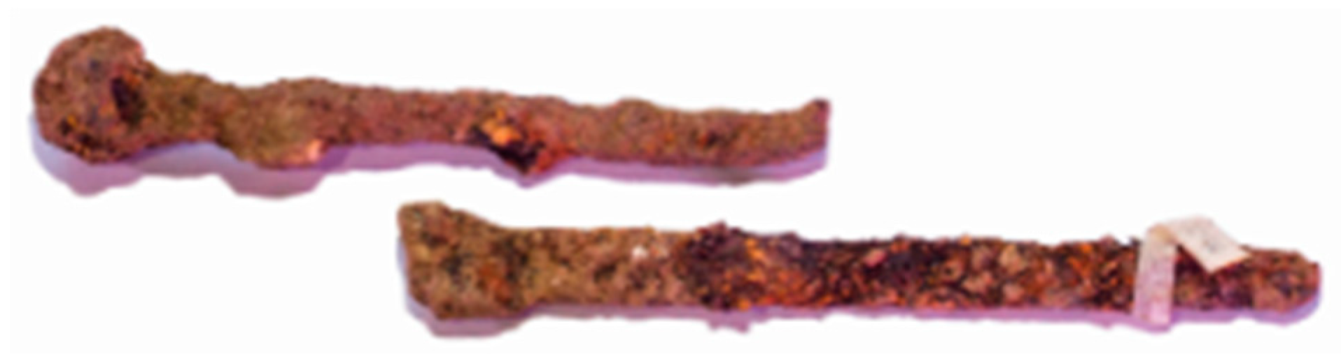
Figure 14.
Heavily corroded bronze coins recovered from Ravne 3, diameters 1–1.5 cm. This group of small bronze coins, each measuring between 1.0 and 1.5 centimeters in diameter, was recovered during excavation of the Ravne 3 tunnel. The coins are in a highly corroded state, with surfaces obscured by verdigris and oxidation layers, rendering precise typological identification difficult. Their material composition allowed for slightly better preservation under the humid underground conditions compared to ferrous artifacts. Source: Osmanagich, S., Hoyle, R., Agić, A., & Delibašić, H. (2023). Ravne 3 Tunnels (1st ed.). Archaeological Park: BPS Foundation, p. 71.
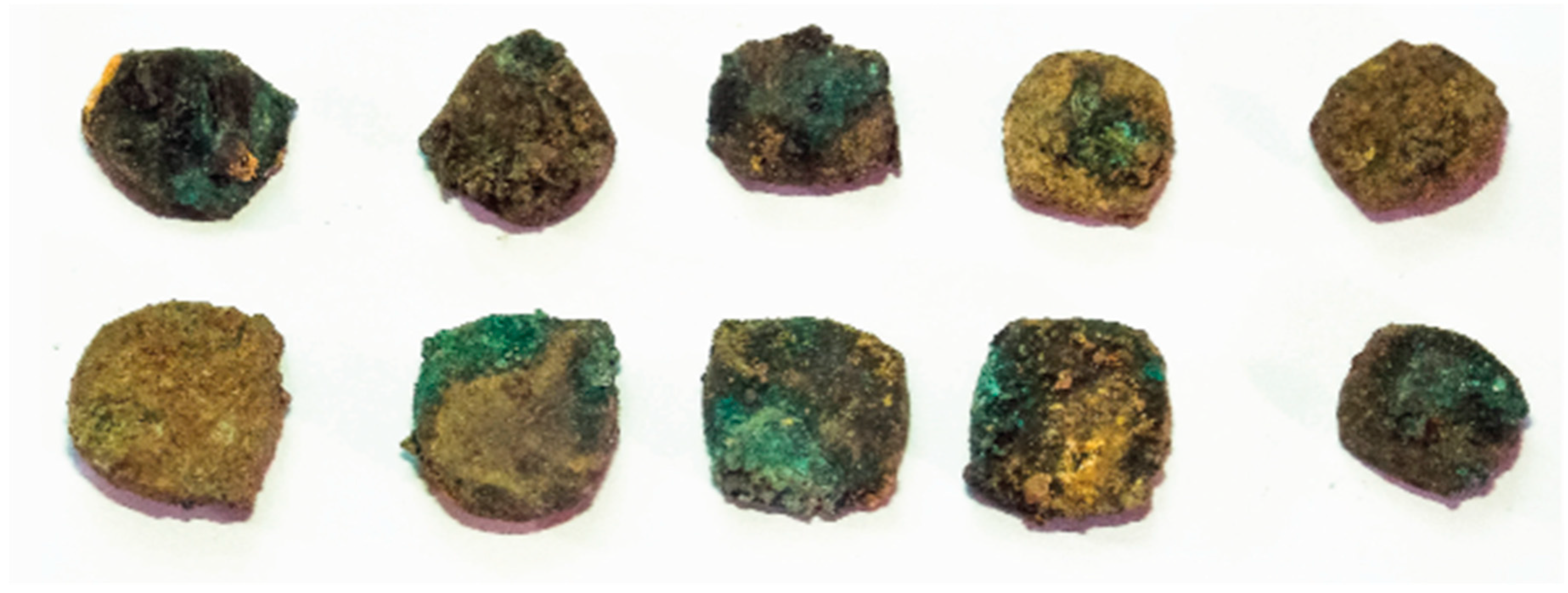
Figure 15.
Bronze pendant featuring abstract Celtic-style motif, possibly dating to the Roman period. This finely crafted bronze pendant, measuring approximately 1.5 cm in diameter, was recovered from the Ravne 3 tunnel. It features a symmetrical, abstract design stylistically associated with Celtic ornamental traditions, rendered in low-relief engraving. The presence of three perforations suggests it may have functioned as a decorative clothing or harness fitting, or possibly as an amulet. Based on stylistic and material comparisons with similar artifacts from the wider Balkan region, the object is tentatively dated to the Roman period, though its motif likely preserves older cultural influences. Source: Osmanagich, S., Hoyle, R., Agić, A., & Delibašić, H. (2023). Ravne 3 Tunnels (1st ed.). Archaeological Park: BPS Foundation, p. 70.
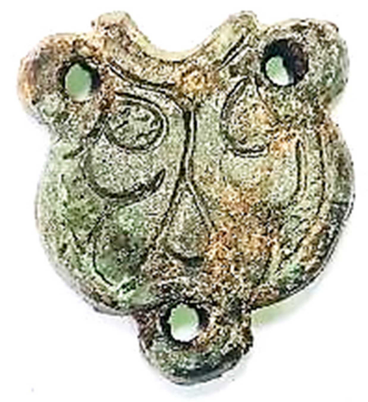
Figure 16.
Roman roof tile (tegula) fragment with Celtic-knot motif, recovered from the Ravne 3 tunnel. This fragmentary ceramic roof tile, measuring 41 cm in length and 6 cm in height, is identified as a Roman tegula. The tile bears an incised Celtic-knot motif in one corner and is composed of ceramic fabric containing carbonaceous sand inclusions, suggesting possible production from local Visoko-area clay. It represents one of the few ceramic fragments attributable to the Roman period found in Ravne 3, contrasting with the predominance of later medieval coarse domestic wares. Source: Osmanagich, S., Hoyle, R., Agić, A., & Delibašić, H. (2023). Ravne 3 Tunnels (1st ed.). Archaeological Park: BPS Foundation, pp. 66–67.
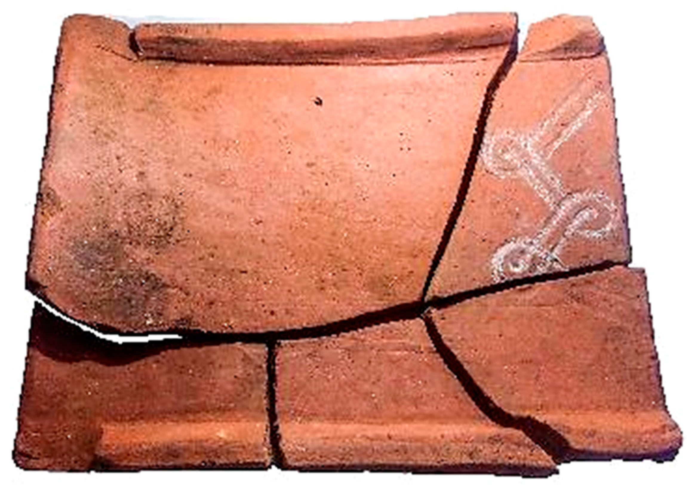
Figure 17.
Fragmented Roman Terra Sigillata vessel recovered from Ravne 3. This partially reconstructed luxury ceramic vessel is made of Roman Terra Sigillata, a fine red-slipped ware typical of Roman provincial tableware. The bowl has a diameter of approximately 11 cm, and although incomplete, several diagnostic fragments with characteristic surface sheen and stamped decoration remain intact. Terra Sigillata vessels were widely used across the Roman Empire for serving food and liquids and are typically associated with high-status domestic or ceremonial contexts. Its presence in the Ravne 3 tunnel suggests either trade contact or cultural transmission during the Roman period. Source: Osmanagich, S., Hoyle, R., Agić, A., & Delibašić, H. (2023). Ravne 3 Tunnels (1st ed.). Archaeological Park: BPS Foundation, p. 67.
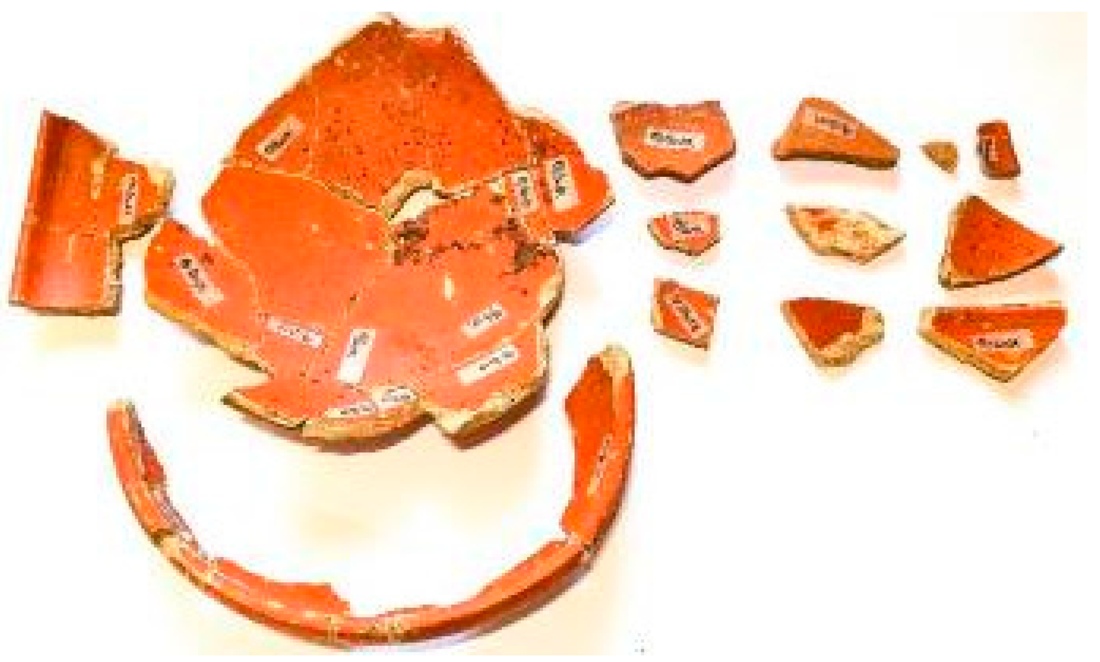
Figure 18.
Partially reconstructed Roman Terra Sigillata vessel from Ravne 3 (diameter: 11 cm). This photograph shows a partially reconstructed Roman ceramic bowl made of Terra Sigillata, characterized by its red glossy surface and fine-walled construction. The bowl measures approximately 11 cm in diameter, and its rim, body, and base fragments exhibit typical curvature and fabric of Roman tableware used across imperial provinces. It was likely used for serving food or drink and is among the few luxury-status ceramic artifacts recovered in the Ravne 3 tunnel, indicating possible Roman-period activity or secondary deposition. Source: Osmanagich, S., Hoyle, R., Agić, A., & Delibašić, H. (2023). Ravne 3 Tunnels (1st ed.). Archaeological Park: BPS Foundation, p. 67.
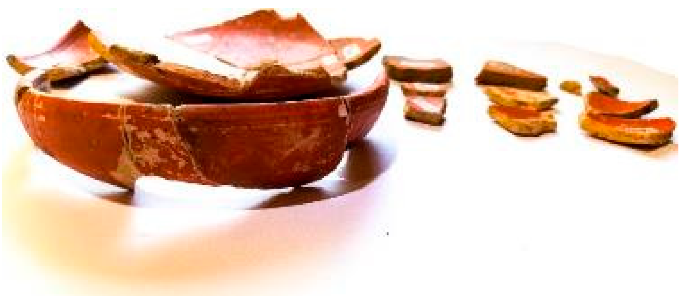
Figure 19.
Examples of ceramic sherds with simple linear ornamentation from the Ravne 3 tunnels. These three pottery fragments, each measuring approximately 4 to 5 cm in length, display simple linear decorative patterns incised or impressed into the surface before firing. The ceramics are typical of low-fired domestic wares associated with the Bosnian medieval period and were recovered from the upper fill layers of the Ravne 3 tunnel chambers. Their thin walls and minimal ornamentation suggest utilitarian use, likely related to food preparation or storage. Source: Osmanagich, S., Hoyle, R., Agić, A., & Delibašić, H. (2023). Ravne 3 Tunnels (1st ed.). Archaeological Park: BPS Foundation, p. 69.
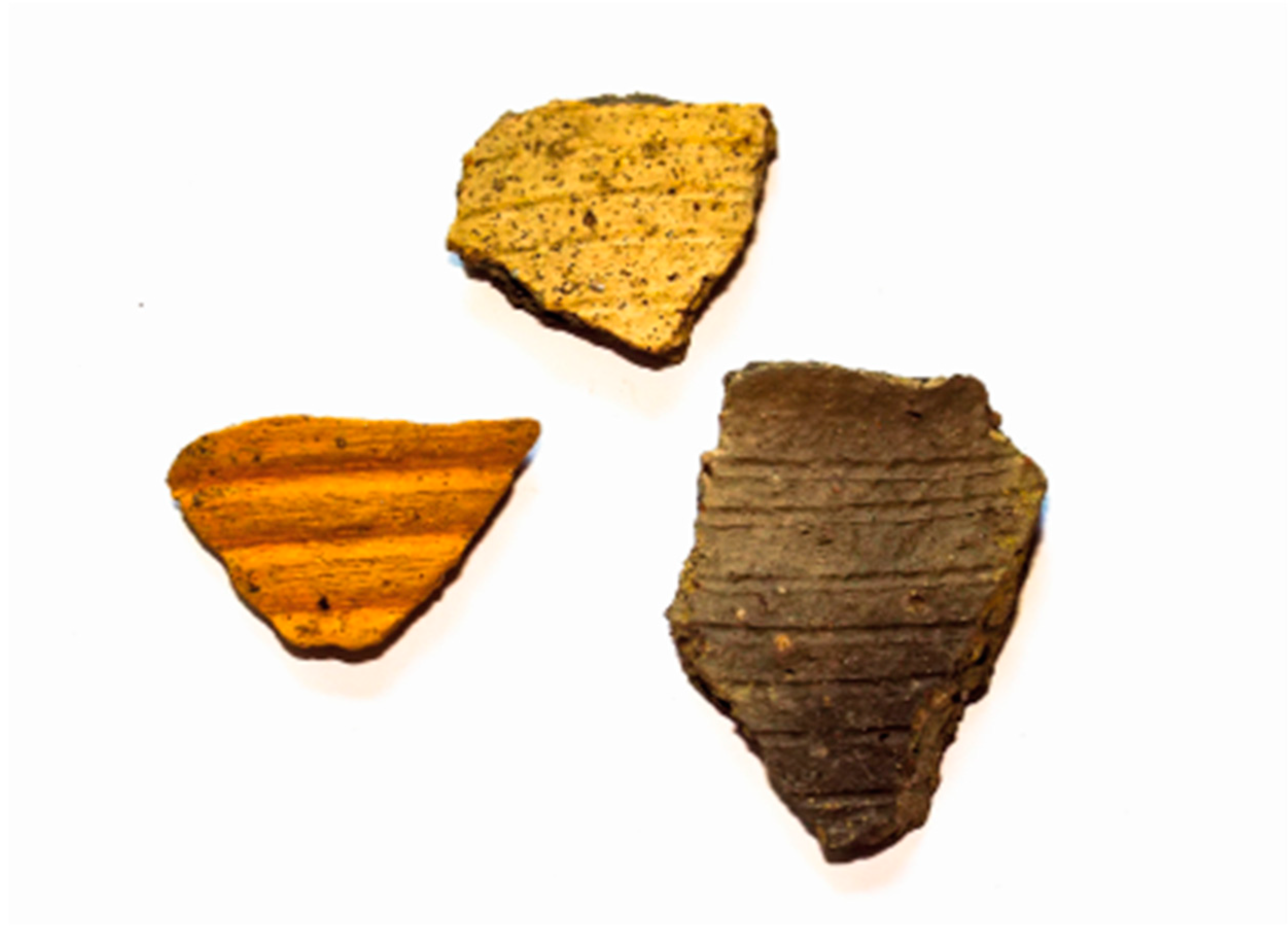
Figure 20.
Rim fragments of a medieval cooking pot from Ravne 3, with coarse fabric and linear decoration. These ceramic sherds represent rim fragments of a Bosnian medieval cooking vessel, measuring between 6.5 and 16 cm in length. The pieces exhibit a simple linear decorative band and contain visible sand temper, indicating local clay sources and low-quality craftsmanship typical of utilitarian domestic wares. Such vessels were likely handmade and intended for everyday use in food preparation or storage. The fragments were recovered from the fill deposits of the Ravne 3 tunnel. Source: Osmanagich, S., Hoyle, R., Agić, A., & Delibašić, H. (2023). Ravne 3 Tunnels (1st ed.). Archaeological Park: BPS Foundation, p. 69.
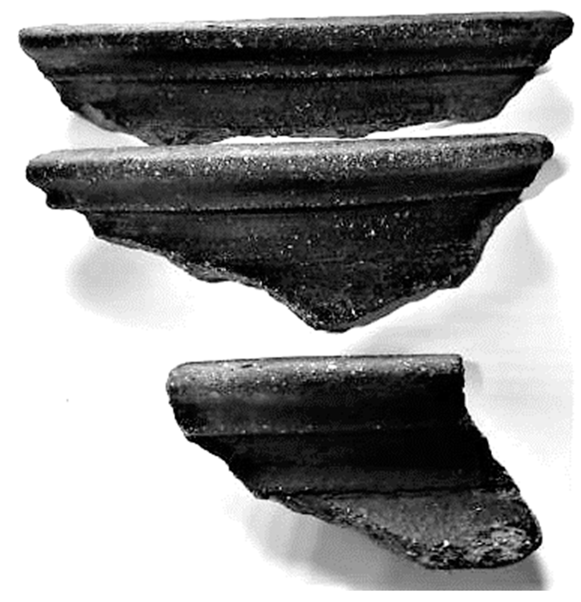
Figure 21.
Partially reconstructed medieval ceramic vessel from Ravne 3. This handmade ceramic vessel, 21 cm in height and 13 cm in width, represents a partially reconstructed indigenous Bosnian pot from the medieval period. Despite substantial fragmentation, the vessel's flaring rim and globular body remain distinguishable. Its coarse texture and dark coloration suggest low-temperature firing using local clays, typical of utilitarian domestic ware. The vessel was recovered from fill deposits within the Ravne 3 tunnel and reassembled from multiple sherds. Source: Osmanagich, S., Hoyle, R., Agić, A., & Delibašić, H. (2023). Ravne 3 Tunnels (1st ed.). Archaeological Park: BPS Foundation, p. 68.
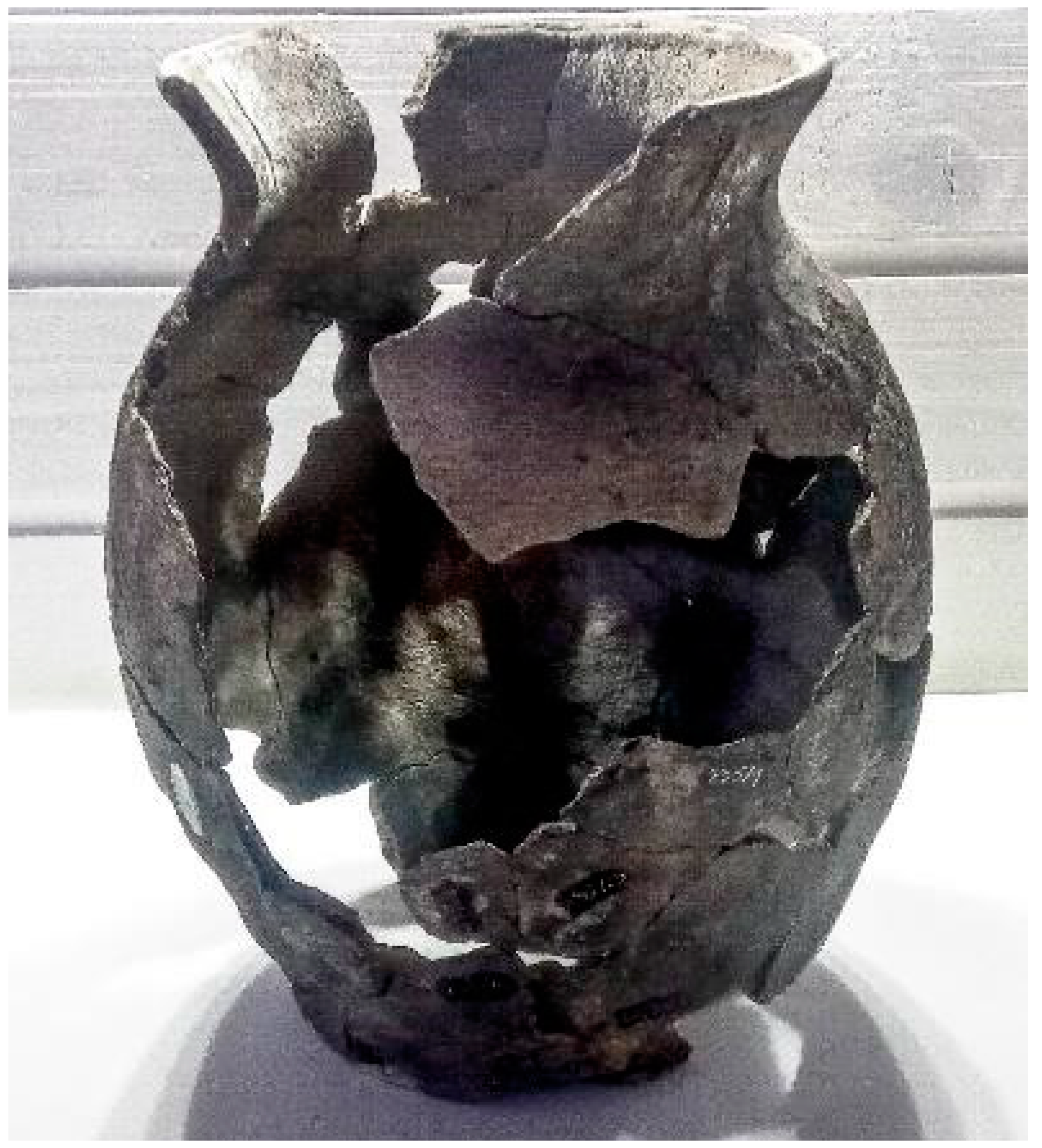
Figure 22.
Fragments of medieval pottery from the Ravne 3 tunnels: vessel rim and base. This image shows two examples of medieval ceramic fragments recovered from the Ravne 3 tunnel complex. On the left, a well-preserved rim and neck section of a vessel with a slightly flared lip, typical of handmade cooking or storage pots. On the right, a partially reconstructed base of another vessel, revealing the coarse texture and blackened surface resulting from low-temperature firing. Both artifacts reflect utilitarian domestic use and are representative of local ceramic production during the medieval period. Source: Osmanagich, S., Hoyle, R., Agić, A., & Delibašić, H. (2023). Ravne 3 Tunnels (1st ed.). Archaeological Park: BPS Foundation, p. 68.
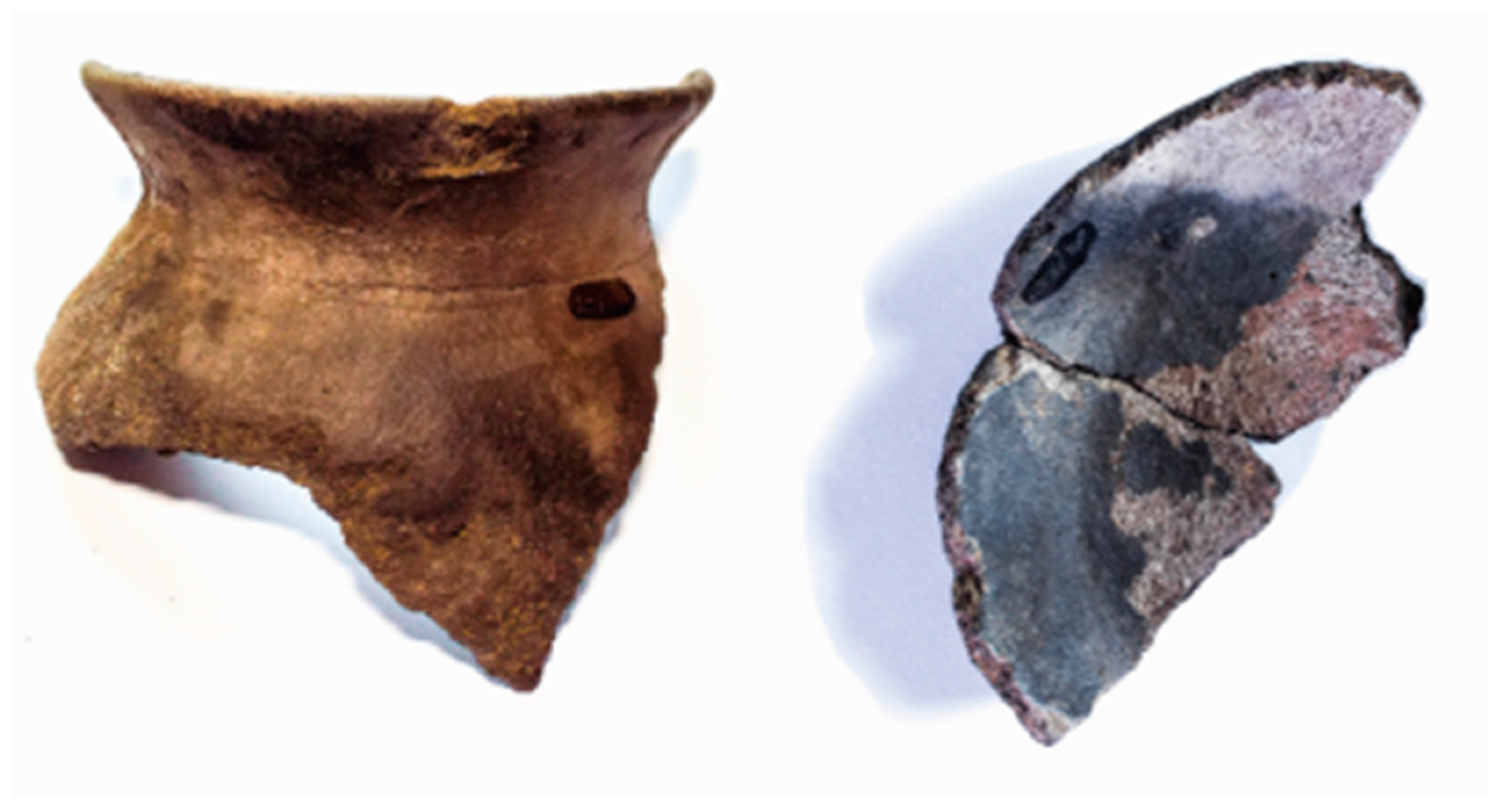
Figure 23.
Stalactites and stalagmites in an undisturbed section of the Ravne 3 tunnel. This image shows an active speleothem formation zone within the Ravne 3 tunnel system. Stalactites can be seen descending from the conglomerate ceiling, while stalagmites are visible rising from the compact tunnel floor, indicating prolonged periods of water percolation and calcite deposition. Such formations develop slowly over centuries or millennia in stable underground microclimates, providing important clues to the long-term undisturbed nature of the environment. Photo by Dr Sam Osmanagich. Source: Osmanagich, S., Hoyle, R., Agić, A., & Delibašić, H. (2023). Ravne 3 Tunnels (1st ed.). Archaeological Park: BPS Foundation, p. 16.
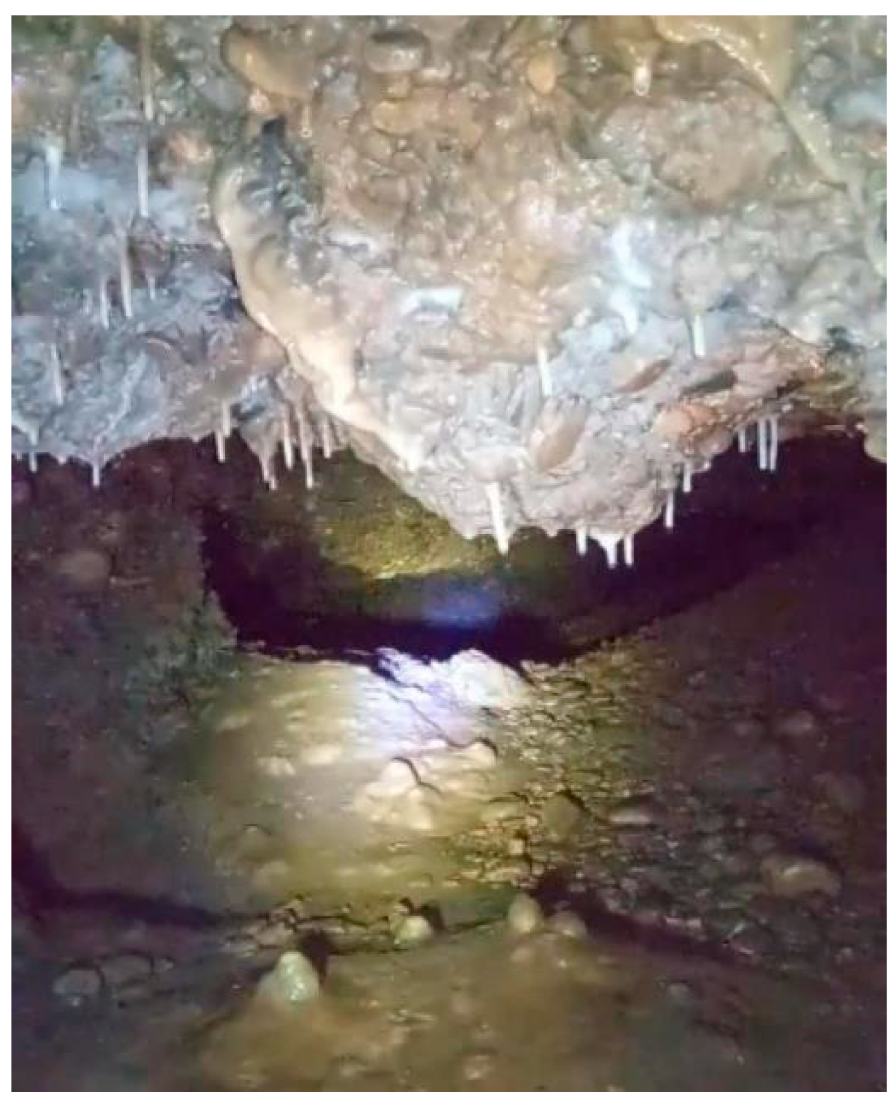
Figure 24.
Conical stalagmites in the Ravne 3 tunnel with radiometric dating sample points S001 and S002. This image shows well-formed conical stalagmites on the tunnel floor of Ravne 3, with clearly labeled sample points S001 and S002. These speleothems were selected for radiometric dating to help determine the minimum age of the tunnel’s last phase of undisturbed environmental stability. The stalagmites’ intact formation suggests prolonged periods without significant human disturbance or flooding. Source: Osmanagich, S., Hoyle, R., Agić, A., & Delibašić, H. (2023). Ravne 3 Tunnels (1st ed.). Archaeological Park: BPS Foundation, p. 55.
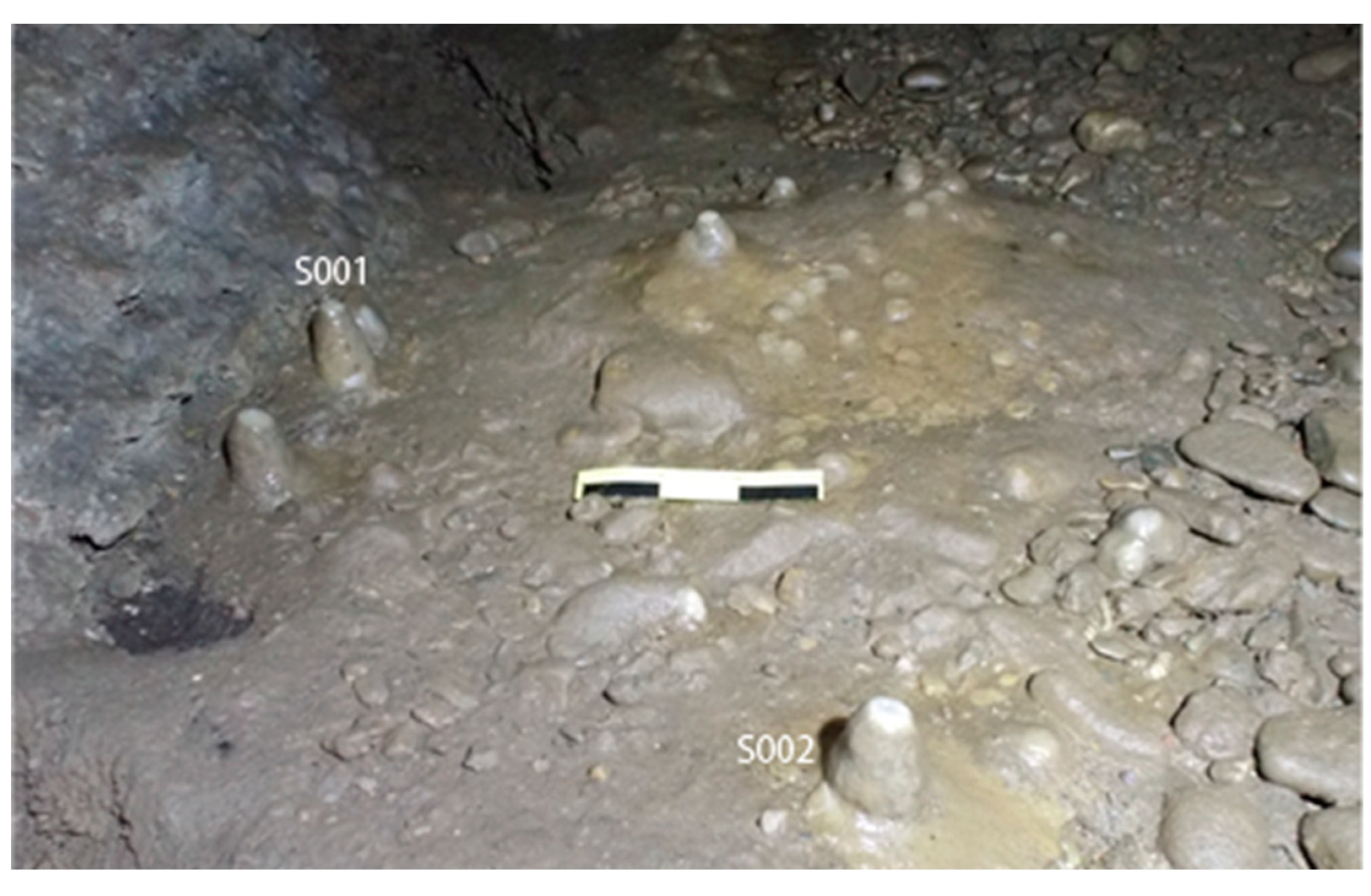
Figure 24.
Conical stalagmites in Ravne 3 tunnel, with S002 prepared for Uranium-Thorium dating. The upper image shows the conical stalagmites S001 and S002 located on the tunnel floor of Ravne 3, identified for radiometric analysis. In the lower panels, stalagmite S002 is shown in detail: it has been sectioned vertically to extract a clean carbonate sample from the basal layer, necessary for U-Th dating. The laminar growth patterns are clearly visible, indicating continuous calcite deposition. This dating method was employed to help establish a minimum age for undisturbed tunnel sedimentation and ceiling integrity. Photo credits: Upper image by Dr Sam Osmanagich; lower images from sample documentation. Source: Osmanagich, S., Hoyle, R., Agić, A., & Delibašić, H. (2023). Ravne 3 Tunnels (1st ed.). Archaeological Park: BPS Foundation, p. 55.
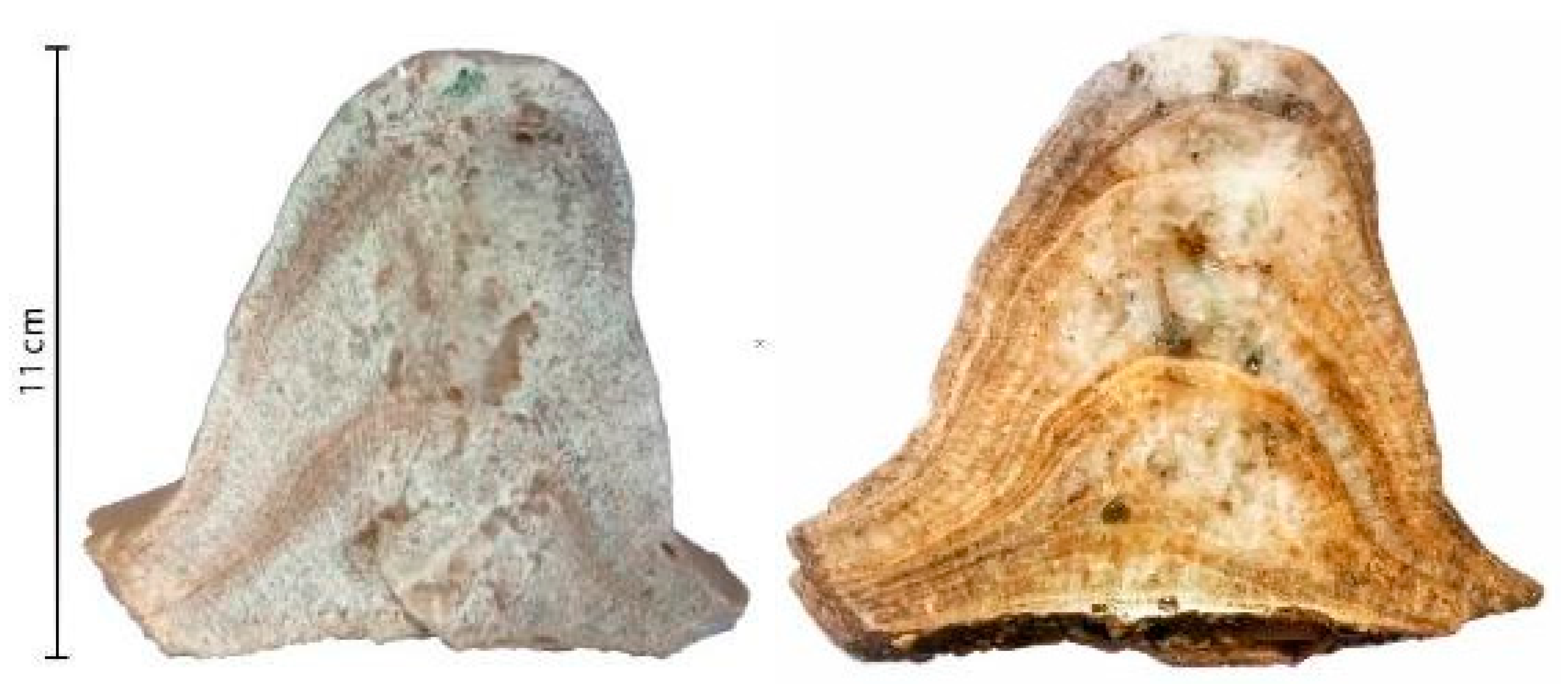
Figure 25.
Original documentation of Uranium-Thorium dating for stalagmite sample S002 from Ravne 3. This figure presents excerpts from the official U-series dating report for stalagmite S002, conducted by the Institute of Geological Sciences, Polish Academy of Sciences (Warsaw) in collaboration with the Institute of Geology CAS (Prague). The analyzed sample (S002/B5) was extracted from the basal portion of the stalagmite and chemically processed for uranium and thorium separation using TRU-resin chromatography. Isotopic measurements were conducted using a double-focusing sector-field ICP-MS (Element 2, Thermo Finnigan). The corrected age of the sample, accounting for detrital contamination (232Th), was calculated as 5.9 ± 0.3 ka BP. This provides a minimum age for the formation of the stalagmite and, by extension, the last undisturbed phase of the tunnel floor where the speleothem developed. Source: U/Th Dating Report, Institute of Geology CAS & Polish Academy of Sciences, Work No. 2019-SM. Referenced in: Osmanagich, S., Hoyle, R., Agić, A., & Delibašić, H. (2023). Ravne 3 Tunnels (1st ed.). Archaeological Park: BPS Foundation, p. 84.

Work no.: 2019-SM
Samples quantity: 1
Material: Stalagmite
Remarks: 4g of calcite powder selected from basal part of stalagmite S002. Sample marked as S002/B5
Method Description:
Chemical procedure of uranium and thorium separation
After thermal decomposition of organic matter a 233U-236U-229Th spike is added to samples before any further chemical treatment. Calcite sample is dissolved in nitric acid. Uranium and thorium is separated from carbonate matrix using chromatographic method with TRU-resin Chemical procedure has been done in U-series Laboratory of Institute of Geological Sciences, Polish Academy of Sciences (Warsaw, Poland). Internal standard sample and blank sample were prepared simultaneously any series of studied samples.
Measurement
Isotopic composition of U and Th measurement has been performed in Institute of Geology of the CAS, v. v. i. (Prague, Czech Republic). Measurements were performed with a double-focusing sector-field ICP mass analyzer (Element 2, Thermo Finngan). The instrument was operated at a low mass resolution (m/Δm ≥ 300). Measurement results were corrected for counting background and chemical blank.
| Lab. no. | Sample | U cont. [ppm] | 234U/238U | 230Th/234U | 230Th/232Th | Age [ka] |
Corrected age [ka] |
| 1290 | S002/B5 | 0.0288±0.0001 | 1.279±0.004 | 0.077±0.002 | 2.53±0.08 | 8.8 ± 0.2 | 5.9 ± 0.3 |
Reported errors are 2 standard deviations.
Results:
General remarks:
Isotope of 232Th indicates the potential contamination of the sample by thorium and uranium from detrital source. The ages obtained were thus adjusted for detrital contamination indicated by the presence of 232Th using the typical silicate activity ratio 230Th/232Th of 0.83 (± 0.42) derived from the 232Th/238U activity ratio of 1.21 (± 0.6), 230Th/238U activity ratio of 1.0 (± 0.1) and 234U/238U activity ratio of 1.0 (± 0.1) (cf. Cruz et al., 2005).
Cruz Jr., F., W., Burns, S.J., Karmann, I., Sharp, W.D., Vulle, M., Cardaso, A.O., Ferrari, J.A., Dias, P.L.S., Vlana Jr., O., 2005. Insolation-driven changes in atmospheric circulation over the past 116,000 years in subtropical Brazil. Nature 434, 63–65.
Figure 26.
Calibrated radiocarbon dating result for speleothem sample from Ravne 3, analyzed by the C14 Laboratory in Kiev. This chart presents the radiocarbon dating results provided by the Conventional Radiocarbon Dating Laboratory, Kiev, Ukraine, for a speleothem sample collected in the Ravne 3 tunnel. The calibrated age, using the IntCal13 atmospheric curve and OxCal v4.3.2 software, places the sample at a 95.4% probability between 2489 and 2199 cal BC, with a smaller peak between 2161 and 2153 cal BC. The radiocarbon determination (uncalibrated) was 3732 BP with an error margin of ±55 years. This result supports the hypothesis that portions of the tunnel system have remained undisturbed since the Late Neolithic to Early Bronze Age. Source: Conventional Radiocarbon Dating Laboratory, Kiev. Referenced in: Osmanagich, S., Hoyle, R., Agić, A., & Delibašić, H. (2023). Ravne 3 Tunnels (1st ed.). Archaeological Park: BPS Foundation, p. 95.
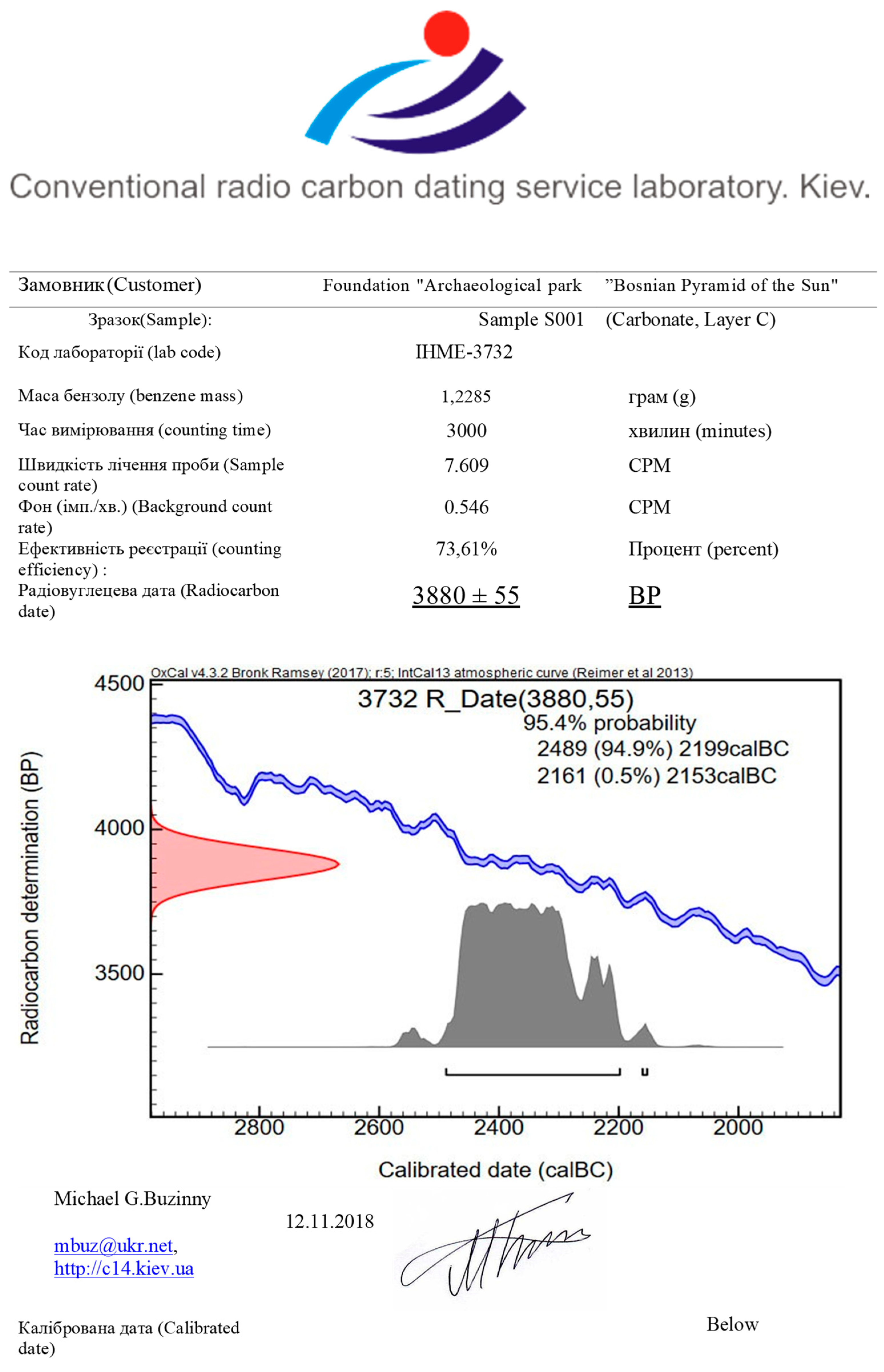
Figure 27.
Radiocarbon Dating Results from Ravne 3 (p. 88–89). This table summarizes the radiocarbon dating results of organic samples from Ravne 3, analyzed at the Conventional Radiocarbon Dating Laboratory, Kiev. The data includes benzene mass, percent modern carbon (pMC), and calculated radiocarbon ages in years before present (BP).
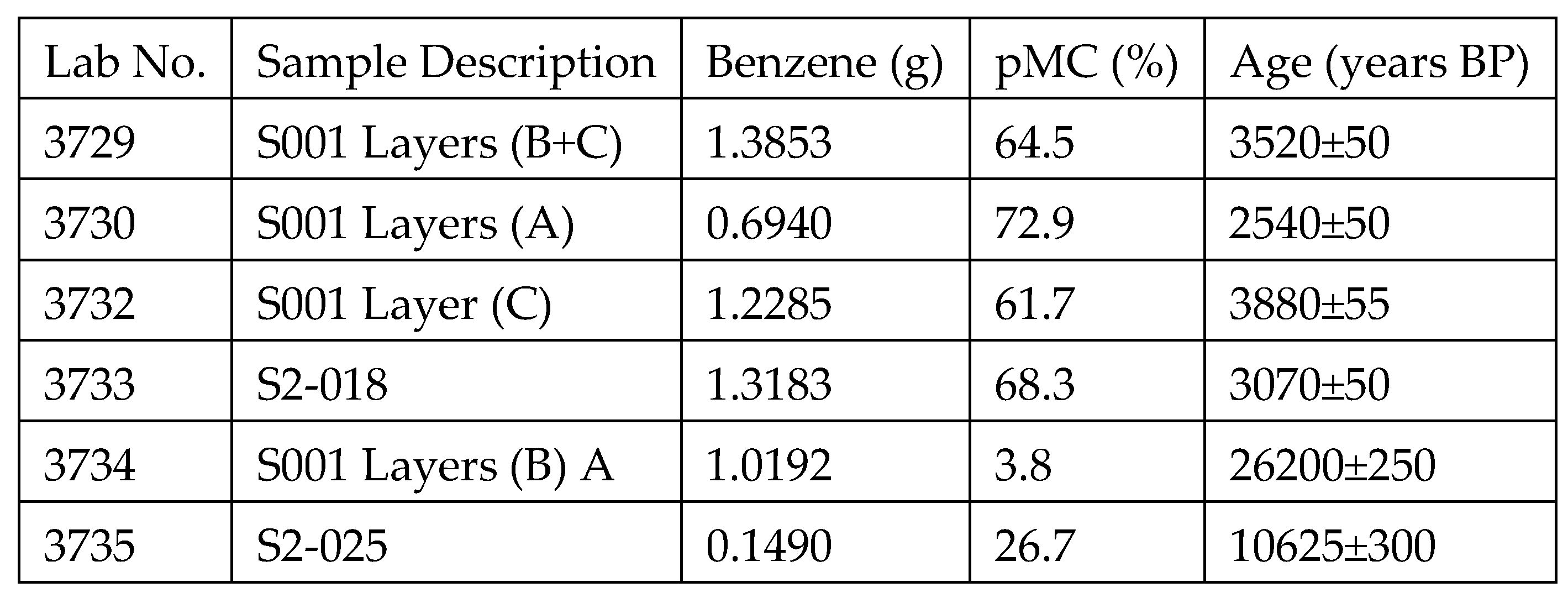
Figure 28.
Official radiocarbon dating result for organic material recovered from Ravne 3, issued by TÜBİTAK Marmara Research Center (Turkey). In 2023, charred organic remains were discovered embedded in a dry-stone wall (suhozid) within the Ravne 3 tunnel system. The material was sampled and submitted to the Radiocarbon Laboratory of the Marmara Research Center (P.K. 21, 41470 Gebze, Turkey), part of the Scientific and Technological Research Council of Turkey (TÜBİTAK). The analysis, supervised and officially signed by Prof. Dr. Mehmet Ergin, was completed in early 2024. Results indicate that the material dates to the 4th century CE, placing its origin within the Roman period. The burnt material likely originated from a temporary hearth or fire feature, suggesting brief human presence or use of the tunnel during Roman occupation. This interpretation is consistent with the stratified ceramic finds from Ravne 3, which span Neolithic, Roman, Byzantine, and Medieval cultural layers. The result offers further confirmation of multi-period continuity of human activity in the Visoko Valley and reinforces the cultural importance of the Ravne 3 tunnel system. Source: Internal documentation, Archaeological Park: BPS Foundation (2024). Radiocarbon analysis conducted by TÜBİTAK Marmara Research Center, Radiocarbon Dating Laboratory, Gebze, Turkey. Signed by Prof. Dr. Mehmet Ergin.
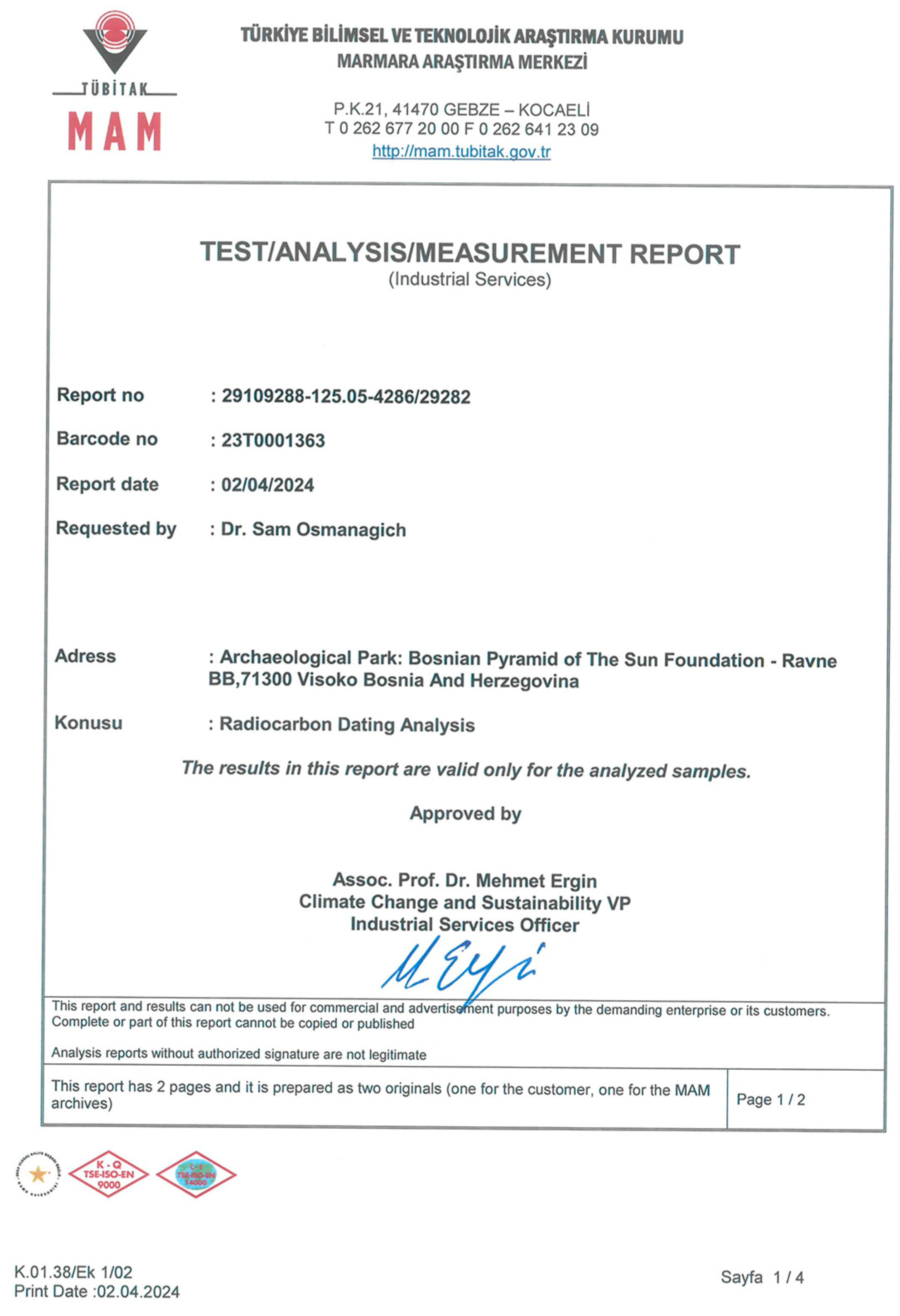
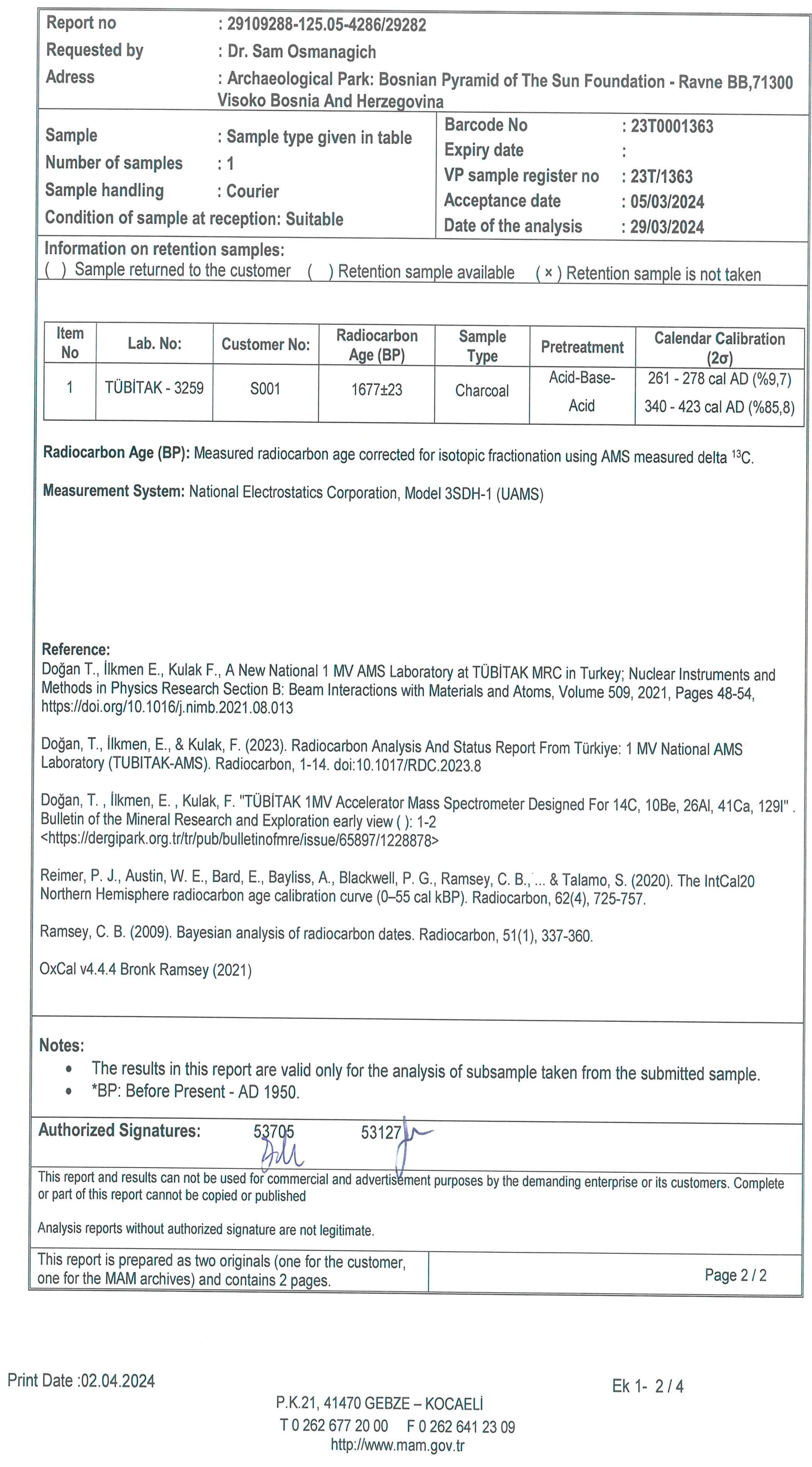
Figure 30.
Environmental Measurements in Ravne Tunnel (February 10, 2024). This table summarizes the environmental readings recorded at various locations within the Ravne Tunnel complex on February 10, 2024, under cloudy weather conditions. Measurements were taken at 10:50 AM by researcher Evelina Č. Parameters recorded include temperature, relative humidity, ion concentration, oxygen level, nuclear radiation, and electromagnetic radiation. All values indicate a stable and clean microclimate inside the tunnel system, with consistently elevated negative ion levels and minimal electromagnetic or nuclear background radiation.
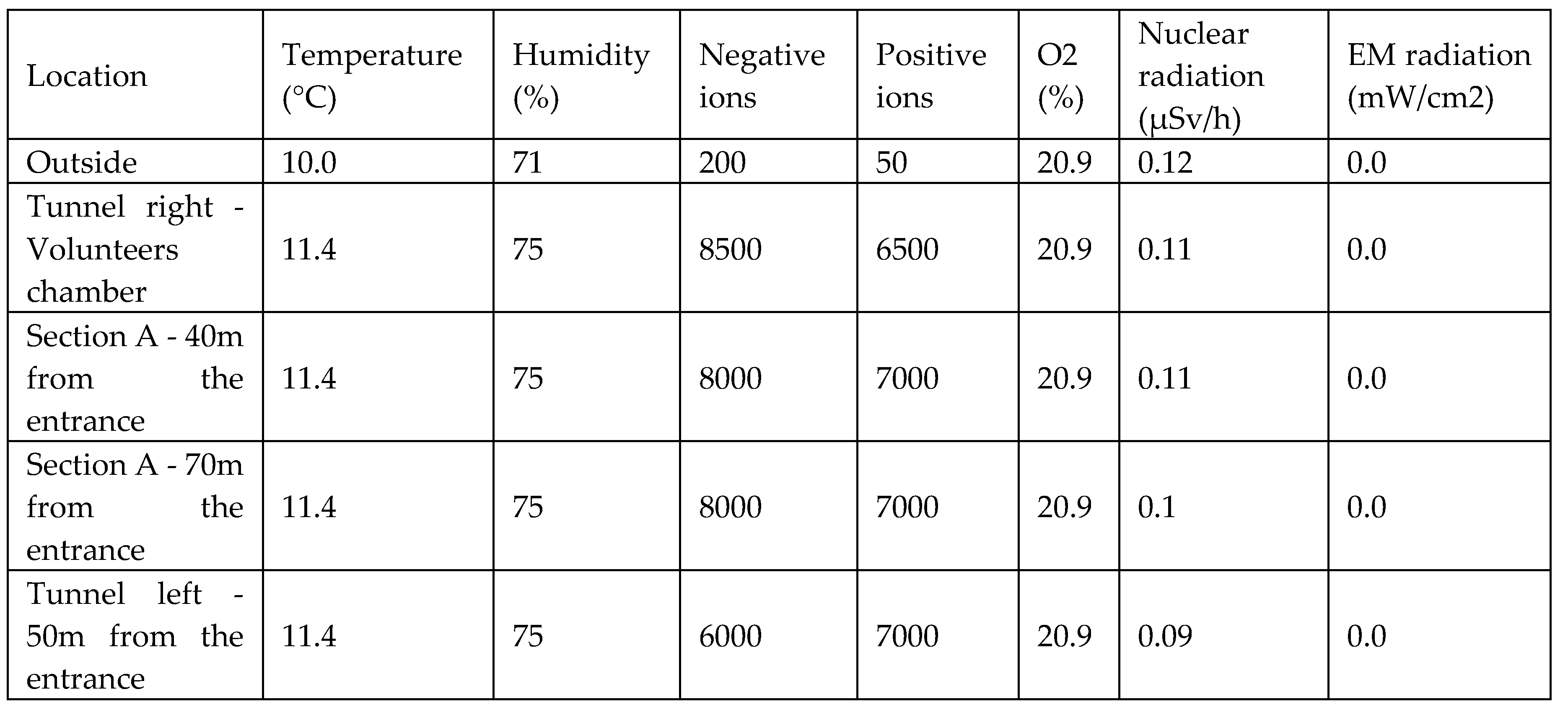
Figure 31.
Energy parameter measurements within the Ravne 3 Tunnel conducted by Evelina Čehajić. This figure presents raw measurement readouts of energetic values recorded inside the Ravne 3 tunnel. The values were obtained using specialized field instruments by Evelina Čehajić, an environmental researcher affiliated with the Archaeological Park: BPS Foundation. Data were collected at several points along the tunnel route and reflect electromagnetic radiation levels, negative ion concentrations, and environmental stability. The graphical form allows visual comparison across locations, emphasizing the uniform low electromagnetic radiation and elevated negative ion levels that typify the tunnel's interior. Source: Evelina Čehajić, internal technical documentation, Archaeological Park: BPS Foundation (2024).
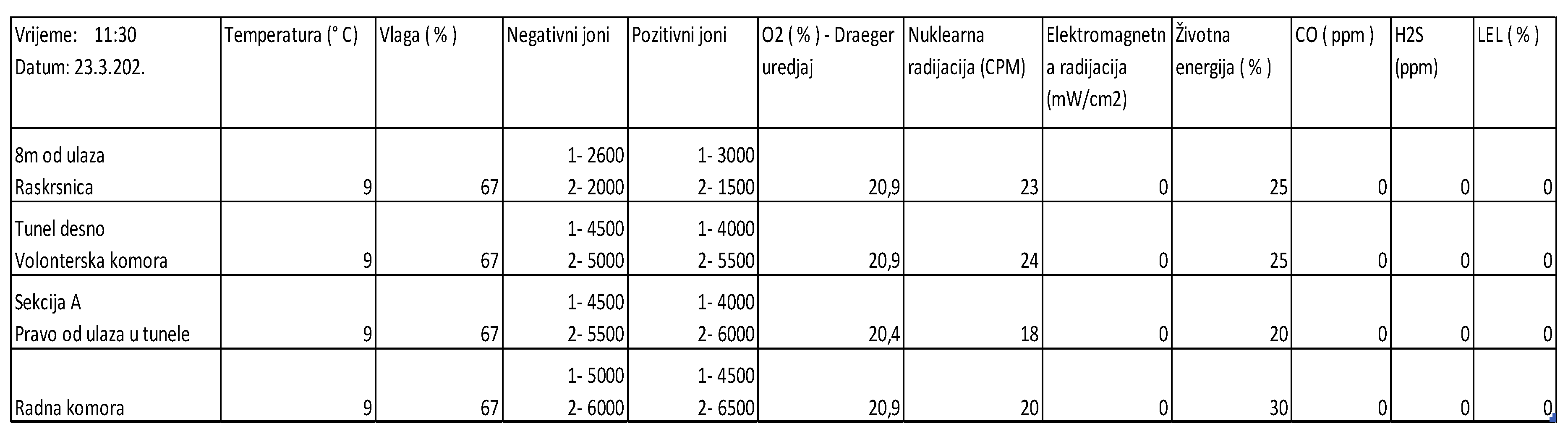
Figure 32.
Stratigraphic layers of trench A302, Ravne 3 Tunnel (2021). This image documents the stratigraphy of archaeological trench A302, excavated in Section A3 of the Ravne 3 Tunnel Complex during the 2021 season. The vertical profile reveals multiple sedimentological horizons, with clearly marked stratigraphic units. The photo is part of the internal technical documentation maintained by the Archaeological Park: BPS Foundation and serves as a visual reference for depth-controlled sampling and dating procedures. Excavations at this location have yielded radiocarbon-datable material, ceramic fragments, and consolidated sedimentary features consistent with anthropogenic modification. Source: Archaeological Park: BPS Foundation, internal excavation archive, 2021.
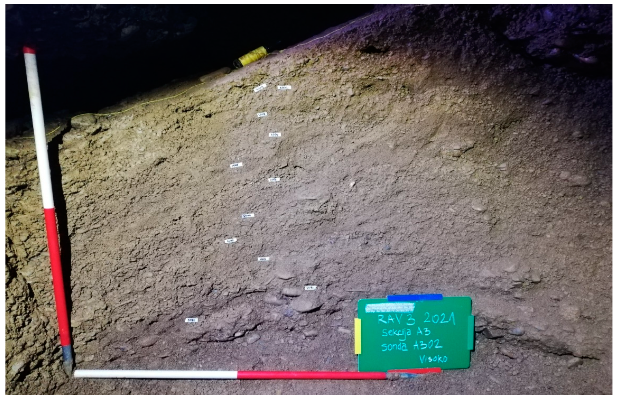
Figure 33.
Dry-stone wall segment discovered within the Ravne 3 Tunnel Complex. This is one of five such structures identified between 2018 and 2024, each composed of unbonded river cobbles methodically stacked without visible use of mortar or binding agents. The orientation and construction method are consistent with documented suhozid features in other sections of the Ravne tunnel system, suggesting intentional passage blocking and possible secondary tunnel modifications. Source: Archaeological Park: BPS Foundation (Field documentation archive, 2024).
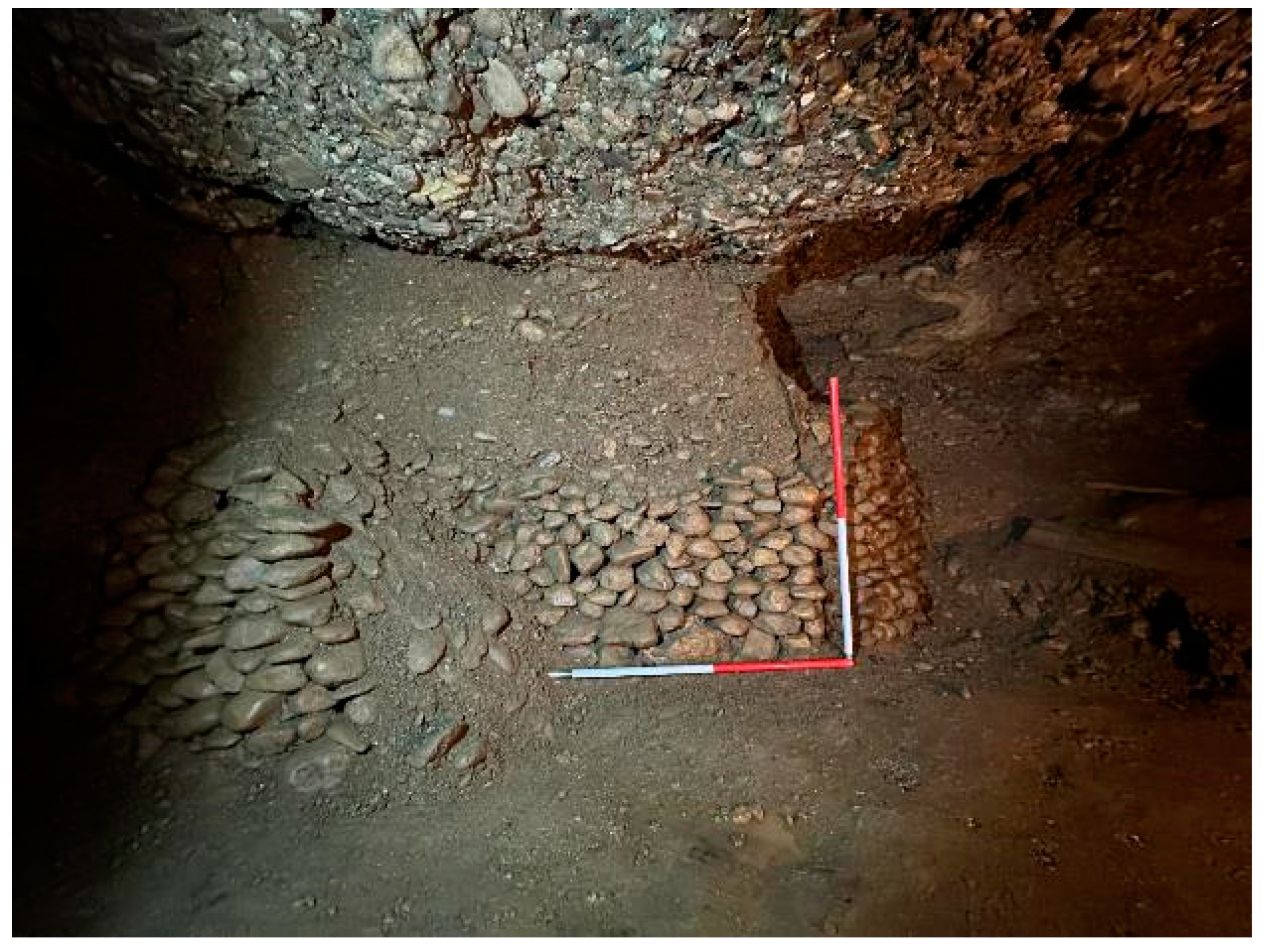
References
- Osmanagich, S., Hoyle, R., Agić, A., Delibašić, H. (2023). Ravne 3 Tunnel. Archaeological Park: BPS Foundation.
- Institute of Geology CAS & Polish Academy of Sciences. (2019). Uranium-Thorium dating report for stalagmite S002.
- Conventional Radiocarbon Dating Service Laboratory, Kiev. (2024). Radiocarbon calibration report: Lab no. 3732.
- Airborne Technologies GmbH (Austria). (2020). LiDAR survey of Visoko Valley and Ravne Tunnel Complex. Contract No. 01/2020.
- Osmanagich, S., Korotkov, K. (2024). Pyramids: The Influence of Form on the Environment, Part II – Bosnian Pyramids. Acta Scientific Medical Sciences, 8(11).
- Osmanagich, S. (2025). Ravne Tunnels as a Regenerative Environment: Scientific Measurements and Human Testimonials. Acta Scientific Medical Sciences.
- Marjanović, G. (2019). Magnetotelluric Investigation of Ravne 3 Tunnel Complex. Internal report, BPS Foundation.
- Yamada, K., et al. (2006). Negative Air Ions Enhance Immunological Function. International Journal of Biometeorology, 50(5), 259–264.
- Krueger, A. P., & Reed, E. J. (1976). Biological Impact of Small Air Ions. Science, 193(4259), 1209–1213. [CrossRef]
- Kolarž, P. et al. (2012). Environmental Conditions and Atmospheric Ions in Natural Caves. Atmospheric Environment, 50, 128–133.
- Osmanagich, S. (2025). Ravne Tunnels as a Regenerative Environment: Scientific Measurements and Human Testimonials. Acta Scientific Medical Sciences.
- Marjanović, G. (2019). Magnetotelluric Investigation of Ravne 3 Tunnel Complex. Internal Foundation Report.
- Osmanagich, S., Korotkov, K. (2024). Pyramids: The Influence of Form on the Environment, Part II – Bosnian Pyramids. Acta Scientific Medical Sciences, 8(11).
Disclaimer/Publisher’s Note: The statements, opinions and data contained in all publications are solely those of the individual author(s) and contributor(s) and not of MDPI and/or the editor(s). MDPI and/or the editor(s) disclaim responsibility for any injury to people or property resulting from any ideas, methods, instructions or products referred to in the content. |
© 2025 by the authors. Licensee MDPI, Basel, Switzerland. This article is an open access article distributed under the terms and conditions of the Creative Commons Attribution (CC BY) license (http://creativecommons.org/licenses/by/4.0/).
Copyright: This open access article is published under a Creative Commons CC BY 4.0 license, which permit the free download, distribution, and reuse, provided that the author and preprint are cited in any reuse.


