
Submitted:
21 April 2025
Posted:
22 April 2025
You are already at the latest version
Abstract
This study presents a systematic optimization of GTAW welding parameters to achieve a pipe-to-pipe butt weld with a root height consistently below 2 mm when joining stainless steel 316L material, employing the Taguchi design of experiments. The input parameters considered include GTAW welding current, voltage, welding speed, and root gap configurations of 1 mm, 1.5 mm, and 2 mm. Welding was performed according to the Taguchi L-09 experimental design. All 9 welded samples were evaluated using liquid penetrant testing to detect surface-breaking defects such as porosity, laps, and cracks; X-ray radiography to identify internal defects; and profile radiography to assess erosion, corrosion, and root height. Among the nine welded plate samples, the optimal root height (less than 2 mm) was selected and further validated through the welding of a one-pipe sample. An additional macro examination was conducted to confirm the root height and assess the overall root weld integrity and quality.
Keywords:
Design of Experiments (DOE)
; Gas Tungsten Arc Welding (GTAW)
; The American Society of Mechanical Engineers (ASME)
; Analysis of Variance (ANOVA)
; Non destructive testing (NDT)
1. Introduction
Gas Tungsten Arc Welding (GTAW) is a highly versatile welding process widely utilized in industries such as aerospace, automotive, and chemical processing, particularly for joining materials like stainless steel [1]. This process, also known as Tungsten Inert Gas (TIG) welding, is recognized for its ability to produce smooth, high-quality welds with minimal spatter. This characteristic makes it particularly suitable for applications with strict quality requirements. The reduction in spatter not only enhances the aesthetic quality of the weld but also minimizes the need for post-weld cleaning, thereby improving overall efficiency in demanding industrial settings [2,3].
Optimizing welding process parameters is paramount for maintaining the structural integrity, mechanical properties, and overall quality of welded joints [4,5,6]. Inadequate selection of these parameters can lead to various defects, including cracking, porosity, incomplete fusion, and substantial distortion [7]. Root height is crucial in Gas Tungsten Arc Welding, significantly affecting weld penetration and quality [8].
To overcome these challenges, advancements in welding processes and precise control of parameters are essential [9,10]. Taguchi optimization can be employed to analyze and optimize welding process parameters, ensuring the production of high-quality, reliable welds [11,12,13].
Root height, a critical factor influencing the mechanical properties and strength of welded joints, is essential for ensuring the reliability and integrity of pipe-to-pipe joints. In high-strength materials such as stainless steel 316, achieving a root height under 2 mm is particularly crucial in applications like critical pipelines, where even minor defects can lead to significant failures.
Ensuring the integrity of welded joints is even more critical in high-risk environments, such as Ethylene Oxide (EO) production plants. EO, a highly reactive chemical, is produced by reacting Ethylene with Oxygen. Recent operational data indicate six failures in the EO service pipeline system, including multiple leaks traced to excessive weld root protrusion, resulting in unit shutdowns over the past six years. Given the volatile nature of EO, optimizing welding processes becomes paramount to mitigate the risk and ensure the reliability of welded components. To achieve such precision, welding parameters such as current, voltage, welding speed, and root gap must be meticulously optimized.
Improper welding parameters can adversely affect the mechanical properties of welded joints, making them susceptible to stress-induced failures. This highlights the need for the optimization of welding parameters—current, voltage, and speed—to maintain the integrity of welded joints in EO pipelines [14].
Moreover, excessive weld root height in pipes has been shown to disrupt fluid flow by increasing resistance and causing separation and vortex formation. As the Reynolds number approaches the critical threshold, these obstructions lead to a transition from laminar to turbulent flow [15]. This disruption reduces the effective flow area, resulting in higher velocity, pressure drops, and turbulence. Such irregularities can cause cavitation, increased drag, and premature degradation, especially in high-velocity pipelines [16]. Additionally, increased surface roughness, such as that caused by excessive weld root height, accelerates the transition to turbulence, particularly in small-diameter pipes, thereby increasing head losses and reducing flow efficiency [17].
The significance of optimizing Gas Tungsten Arc Welding (GTAW) parameters extends beyond mere technical performance; it plays a critical role in addressing the safety and reliability challenges faced in industries utilizing high-strength materials such as stainless steel 316L. Recent studies have underscored the importance of precision in welding processes, particularly in high-stress environments where the consequences of failure can be catastrophic. For instance, the use of advanced monitoring techniques, such as real-time feedback systems, has been shown to enhance the control of welding parameters, thereby improving weld quality and reducing defects [18]. These innovations facilitate adaptive responses to variations in material properties and external conditions, ensuring more consistent welding outcomes.
Moreover, the integration of machine learning algorithms into the welding process has emerged as a transformative approach, enabling predictive maintenance and optimization of welding parameters. By analyzing historical data and real-time sensor inputs, these algorithms can identify optimal settings for various welding scenarios, thus minimizing root height and enhancing overall weld integrity [19]. This technological advancement aligns with the industry’s shift towards Industry 4.0, where automation and smart manufacturing are becoming increasingly prevalent [20].
In addition to technological innovations, there is a growing body of research focusing on the microstructural implications of welding parameters on the mechanical properties of welded joints. Recent findings indicate that variations in heat input not only affect root height but also significantly influence the microstructural characteristics of the weld metal, leading to variations in strength and ductility [21]. Understanding these relationships is essential for developing comprehensive welding strategies that not only meet dimensional tolerances but also ensure the mechanical performance of welded components in service.
Furthermore, environmental considerations are becoming increasingly important in the optimization of welding processes. The need for sustainable practices in manufacturing has prompted researchers to explore the impact of different welding parameters on energy consumption and material waste. Studies have indicated that optimizing welding parameters can lead to significant reductions in energy use and emissions, contributing to more sustainable manufacturing processes [22].
To the author’s knowledge, no similar studies have been conducted to explore the optimization of welding parameters specifically aimed at minimizing weld root height under 2mm in stainless steel EO pipeline welding applications. This gap in the existing literature highlights the innovative aspect of the current study, which seeks to address these challenges and improve welding precision and joint reliability.
This research addresses these industrial challenges by minimizing weld root height and ensuring high weld quality, using the Taguchi design of experiments (DOE). The research will employ testing methods such as liquid penetrant testing, X-ray radiography, and macro examination to assess weld quality and root height. By optimizing welding parameters and minimizing root height, this work contributes to enhancing the precision and reliability of GTAW welding in stainless steel applications, with a focus on minimizing root height and achieving superior welds.
2. Materials and Methods
2.1. Plate Materials and Method for Experimental Analysis
This experiment utilized 316L stainless steel as the base material and an actual sample size of 100 mm x 100 mm x 6 mm. Before welding, all the test sample surfaces of the base metals and joint configuration were cleaned using a lint-free cloth to ensure the surface was clean and no residue remained. The GTAW process was performed by a certified welder, following the approved Welding Procedure Specification (WPS) as per ASME Section IX [23]. The test specimens were prepared with a single V-groove configuration, featuring a 1 mm root face and a 60-degree included angle. To prevent distortion and mismatch before, during, and after welding, a back support was employed, which also serves to purge at <50 ppm. The complete welding process is illustrated in Figure 1.
To identify the material grade and alloying composition of both the base metal and filler wire was quantified using Positive Material Identification (PMI) with an X-ray fluorescence analyzer, employing a 2-minute exposure time, as detailed in Table 1. Welding parameters, including current, voltage, speed, root gap, visual inspection, target root height, actual root penetration height, oxidation, and profile RT were systematically varied as per the levels listed in Table 2.
The experimental design followed a factorial approach, with specific parameters outlined in Table 2, based on the Taguchi method. All samples were welded with “WEL TIG 316L” filler wire.
2.2. Plate Materials Experimental Outcome
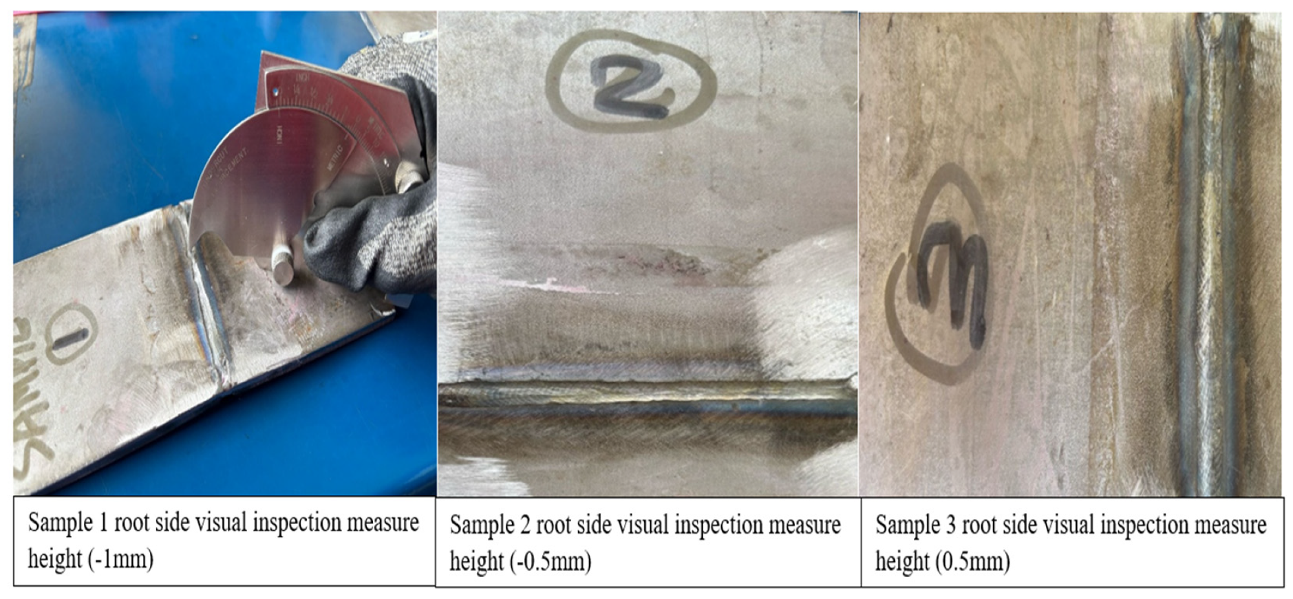
After welding, a visual inspection of the reinforcement and root areas was conducted. All root height was measured using a calibrated welding gauge. The analysis of samples 1 to 3 reveals distinct differences in root height weld quality. Sample 1, with a root height of -1.0 mm, exhibits incomplete penetration and excessive undercutting, which compromises the structural integrity of the weld. This condition is likely caused by improper torch angle or excessive welding speed, leading to a lack of fusion at the root. Such defects can create stress concentrations, making the weld susceptible to failure under load. Sample 2, with a root height of -0.5 mm, shows a slight improvement but still has some degree of undercutting, which could be due to a welding speed that is slightly higher than required. Although this weld is better than the first, it may still be vulnerable to fatigue failure, particularly in applications involving cyclic loading. In contrast, Sample 3, with a root height of 0.5 mm, demonstrates good penetration and reinforcement. The slight positive root reinforcement suggests better fusion and an optimized balance of heat input and travel speed.
Figure 2.
Samples 1 to 3 Root side visual inspection.
All weldments were assessed for defects through non-destructive testing (NDT) without compromising their structural integrity. Radiographic testing, utilizing X-rays or gamma rays, was employed to penetrate the weldments and capture images on film. These radiographic images were analyzed to detect discontinuities, porosity, incomplete penetration, and fractures [24]. The procedure was conducted at a source voltage of 150 keV and a current of 3.5 mA. X-ray imaging is widely used in NDT as it allows for microstructural analysis without causing material damage. Through X-ray or gamma-ray inspection, variations in thickness, structural alterations, internal defects, and assembly details can be effectively identified.
Samples 4, 5, and 6 were visually inspected and measured using a calibrated welding gauge, recording root measurements of 1 mm, 1.5 mm, and 2 mm, respectively. Since all samples passed the visual inspection, they were further examined using profile radiography to verify whether the physical measurements matched the actual internal profiles. In industrial applications, profile radiographic examination is commonly employed to assess the remaining wall thickness and detect corrosion on both the external and internal surfaces of metal components or joints, facilitating precise decision-making [25]. For this analysis, an Ir-192 radioactive source with an activity of 5 Curie was utilized. The profile radiographic results confirmed an exact match with the physical measurements for all three samples, as illustrated in Figure 3.
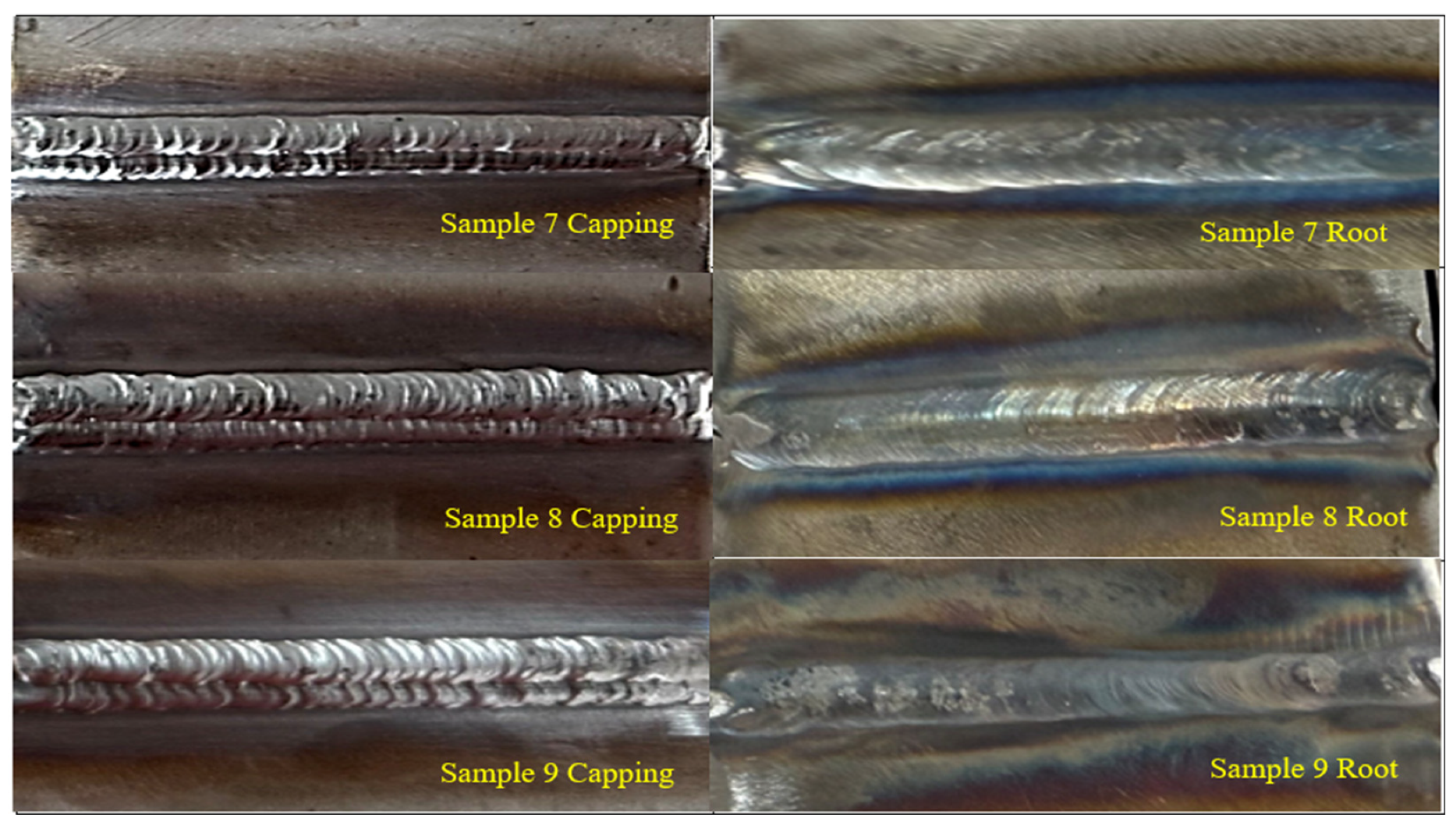
Visual inspections were conducted on the root welds of Samples 7, 8, and 9. The measured root heights were 1.0 mm for Sample 7 and 1.5 mm for Samples 8 and 9. Visual assessment revealed inconsistent bead profiles across all samples, with Samples 8 and 9 showing relatively higher reinforcement compared to Sample 7. Notably, all root samples exhibited poor oxidation control, as indicated by discoloration and surface contamination around the weld beads. Additionally, minor surface irregularities, concavity, and undercut tendencies were observed, particularly in Samples 7 and 9. The presence of oxidation and bead inconsistency may adversely affect the weld integrity and corrosion resistance, indicating the need for cleaning procedures, and controlled welding parameters.
Figure 4.
Showing samples 7, 8, & 9 capping and root area.
2.3. Plate Materials and Method for Experimental Analysis
The L9 experimental trials were performed using plate material positioned in the 2G horizontal orientation, in accordance with ASME Section IX, QW 461.3. Furthermore, a 4-inch Schedule 40S pipe with a wall thickness of 6.02 mm was welded in the 6G position, following ASME Section IX, QW 461.4 [23]. The primary objective of this study was to assess whether the welding parameters optimized for the plate material (specifically sample number 5) and validated through profile radiography would also produce consistent root height measurements in pipe-to-pipe butt welding. This investigation was motivated by the potential influence of positional variation, as transitioning from the 2G to the 6G position may lead to deviations in the weld root height. Figure 5 illustrates the actual setup for pipe welding.
2.4. Visual Inspection and Root Height Measurement of Welded Pipe Joints
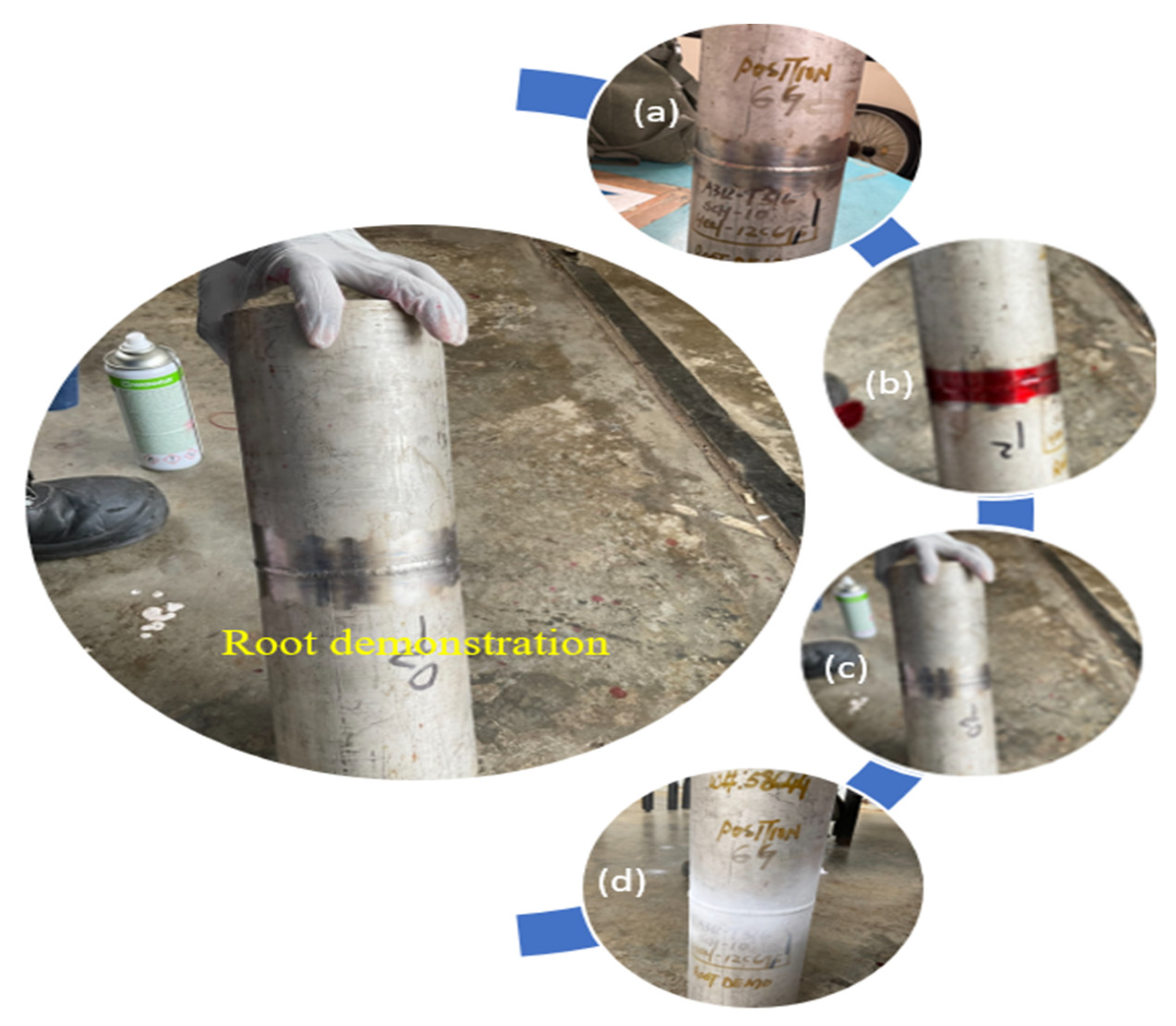
Following the completion of the welding process, a visual inspection of the internal weld root was conducted to assess the quality and uniformity of the weld profile. Additionally, the root height was measured circumferentially at 360° using a calibrated welding gauge to ensure accuracy and consistency. The inspection results indicated that all welding profiles exhibited a smooth and uniform root formation. The measured root height values were recorded at multiple locations around the circumference, and the average root height was determined to be less than 1.5 mm. The detailed measurement results are illustrated in Figure 6.
2.5. Penetrant Testing for Surface Defect Evaluation in Welded Pipe Joints
Penetrant testing was performed on the welded pipe joint to detect surface-breaking defects that may not be visible through visual inspection alone. This non-destructive testing (NDT) method was employed to identify potential discontinuities such as cracks, porosity, or incomplete fusion along the weld reinforcement and heat-affected zone (HAZ). Given the critical nature of weld integrity in pipe joints, ensuring defect-free welds is essential for structural reliability and service performance. The application of penetrant testing enhances the assessment of weld quality by providing a detailed evaluation of surface imperfections, thereby complementing the findings obtained through visual inspection and dimensional measurements. Recent studies have demonstrated the reliability of dye penetrant inspection in detecting weld discontinuities, further validating its effectiveness in ensuring weld integrity [26].
Figure 7.
(a) Surface pre-cleaning; (b) Penetrant drawn into flaws by capillary action; (c) Dwell time and removal of excess penetrant; (d) Developer application reveals flaws through visible indications.
Figure 7.
(a) Surface pre-cleaning; (b) Penetrant drawn into flaws by capillary action; (c) Dwell time and removal of excess penetrant; (d) Developer application reveals flaws through visible indications.
2.6. Radiographic Profile Analysis and Macro Examination of Welded Pipe Joints
A radiographic test (RT) was conducted on the welded pipe joint to detect any potential welding defects. The results revealed that the weld was free from any observable defects. Following the RT, profile radiography was performed to measure the root height, which was found to be less than 1.5 mm, indicating a smooth and uniform weld. To further validate these measurements, the sample was then sent to macro examination to determine the exact root height. The results of the macro examination were consistent with the profile RT measurements, confirming the accuracy of the radiographic assessment. The findings from both the profile radiography and macro examination are presented in Figure 8 below, which illustrates the correspondence between the two methods in evaluating root height and weld quality.
2.7. Welding Parameters for Root Penetration Using Taguchi Method and Genetic Algorithm
This study investigates the optimization of welding parameters for achieving optimal root penetration in Gas Tungsten Arc Welding (GTAW) of mild steel using a combined statistical and evolutionary approach. A Taguchi L9 orthogonal array was employed to design the experiments with four critical process parameters: Amperage, Voltage, Welding Speed, and Root Gap. Regression modeling, ANOVA, signal-to-noise (S/N) ratio analysis, and Genetic Algorithm (GA) optimization techniques were applied to evaluate and optimize weld quality.
The analysis identified the most significant factors influencing root penetration and yielded an optimized parameter setting that meets the quality constraints of penetration < 2 mm, oxidation = 1 (good), 0 = bad and visual inspection score = 1 (good) 0 = bad.
In this work, an integrated approach combining Taguchi DOE, regression modeling, and Genetic Algorithm (GA) is utilized to analyze the impact of four input parameters on root penetration and determine their optimal settings.
The welding experiments were designed using an L9 orthogonal array with the following parameters:
- Amperage: 85 A, 90 A, 100 A
- Voltage: 10 V, 11 V, 12 V
- Speed: 50 mm/min, 60 mm/min, 70 mm/min
- Root Gap: 1.0 mm, 1.5 mm, 2.0 mm
Each trial was evaluated for actual root penetration height, oxidation presence, and visual inspection acceptance. The goal was to achieve a penetration height less than 2 mm.
2.7.1. Regression Model (Enhanced with R² and Model Validation)
A predictive linear regression model was developed to quantify the relationship between the process parameters and root penetration height. The derived model is expressed as (validated with R² = 0.91, RMSE = 0.24):
Penetration = -12.8786 + (0.0929 × Amperage) + (0.4000 × Voltage) + (0.0083 × Speed) + (0.2000 × Root Gap)

Table 3.
Regression model for 9 test samples.
| Sample | Amperage | Voltage | Speed | Root Gap | (0.0929 × Amperage) | (0.4000 × Voltage) | (0.0083 × Speed) | (0.2000 × Root Gap) | Predicted Root Height |
|---|---|---|---|---|---|---|---|---|---|
| 1 | 85 | 10 | 50 | 1 | 7.8965 | 4 | 0.415 | 0.2 | -0.3671 |
| 2 | 85 | 11 | 60 | 1.5 | 7.8965 | 4.4 | 0.498 | 0.3 | 0.2159 |
| 3 | 85 | 12 | 70 | 2 | 7.8965 | 4.8 | 0.581 | 0.4 | 0.7989 |
| 4 | 90 | 10 | 60 | 1 | 8.361 | 4 | 0.498 | 0.2 | 0.1804 |
| 5 | 90 | 11 | 70 | 1.5 | 8.361 | 4.4 | 0.581 | 0.3 | 0.7634 |
| 6 | 90 | 12 | 50 | 2 | 8.361 | 4.8 | 0.415 | 0.4 | 1.0974 |
| 7 | 100 | 10 | 70 | 1 | 9.29 | 4 | 0.581 | 0.2 | 1.1924 |
| 8 | 100 | 11 | 50 | 1.5 | 9.29 | 4.4 | 0.415 | 0.3 | 1.5264 |
| 9 | 100 | 12 | 60 | 2 | 9.29 | 4.8 | 0.498 | 0.4 | 2.1094 |
This model demonstrates that amperage and voltage are the primary contributors to root height, both showing relatively high positive coefficients. This implies that increased current and voltage lead to a higher root height. The model was validated using experimental data from all nine samples, with Sample 5 and Sample 6 showing predicted root heights of 0.7634 mm and 1.0974 mm respectively—both well below the 2 mm threshold, and thus fully satisfying the criteria for optimal weld quality. These predictions confirm the reliability of the regression model and highlight the capability of these parameter combinations to achieve the desired outcomes.
2.7.2. ANOVA
To evaluate the statistical significance and relative contribution of each welding parameter to root penetration height, an Analysis of Variance (ANOVA) was conducted using a Type II model. The results, summarized in Table 4. ANOVA Summary for Root Penetration Height, reveal critical insights into parameter influence.
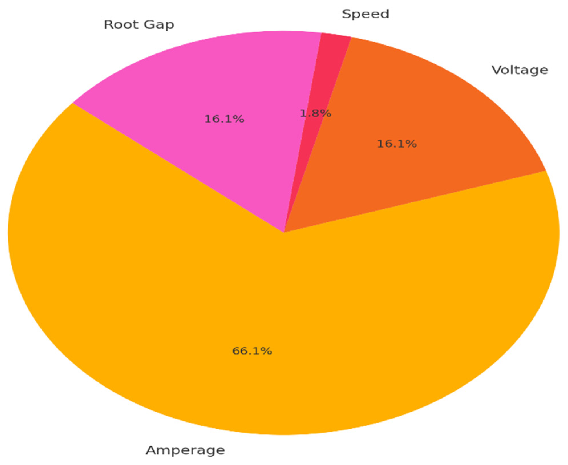
Amperage emerged as the most dominant factor, exhibiting a p-value of 0.026 and contributing approximately 66.1% to the total variance. This statistically significant result (p < 0.05) confirms that fluctuations in welding current substantially affect the depth of root penetration, aligning closely with the trends observed in the regression model and main effects plot. As increased amperage intensifies heat input into the weld pool, it directly impacts fusion at the root, thereby dictating weld geometry and quality.
Voltage and root gap both demonstrated moderate influence, each contributing approximately 16.1% to the response variability, with p-values of 0.100. Although not statistically significant at the 95% confidence level, these parameters play a supportive role. Voltage influences arc energy and fusion width, while root gap governs arc accessibility and filler deposition—both crucial in achieving adequate penetration without excess protrusion.
Welding speed, on the other hand, showed a negligible contribution of just 1.8%, with a p-value of 0.500, indicating minimal statistical relevance within the tested range. Its limited influence may be attributed to the narrow bandwidth of speed levels explored in the experiment (50–70 mm/min), where the effects on heat input per unit length are not pronounced enough to produce substantial variation in root height.
These findings collectively validate the model’s predictive integrity and underscore the necessity of prioritizing amperage control, while judiciously adjusting voltage and root gap to fine-tune penetration. Speed, although operationally important, appears to have minimal statistical leverage under the defined experimental conditions.
Figure 9.
Percentage contribution of each parameter to root penetration height.
2.7.3. Main Effects Plot
A systematic evaluation of process parameters was undertaken to elucidate their individual influence on root penetration height in Gas Tungsten Arc Welding (GTAW) of mild steel. Figure 10 presents the main effects plots (corroborated by regression and S/N analysis), wherein each data point represents the mean root height at varying levels of a single parameter, while holding all others constant. The inclusion of standard deviation error bars further enhances the interpretability of the process variability across the experimental domain.
- Amperage; Amperage exhibited the most dominant effect on root penetration. As amperage increased from 85 A to 100 A, the mean root penetration height rose from –0.33 mm to 1.50 mm, before slightly declining to 1.33 mm. The negative penetration at 85 A is indicative of insufficient arc energy, leading to undercut or lack of fusion at the root. At 90 A, the weld pool attained optimal energy density, producing consistent and desirable penetration depth without oxidation. However, further increase to 100 A, while still yielding acceptable depth, was accompanied by visible oxidation across all samples—implying excessive heat input and degradation of weld pool shielding. These findings reaffirm amperage as the most critical process parameter, warranting precise control to balance between fusion adequacy and metallurgical soundness.
- Voltage; A modest upward trend was observed with increasing voltage. The mean penetration height increased from 0.33 mm at 10 V to 1.33 mm at 12 V, with 11 V delivering an intermediate response of 0.83 mm, which aligns well with stable arc characteristics. Although voltage directly influences arc length and energy dispersal, its impact was less pronounced compared to amperage. This behavior is consistent with literature, which positions voltage as a secondary heat input contributor that modulates, rather than drives, fusion depth.
- Welding Speed; The effect of welding speed on root penetration was nonlinear. At lower speeds (50 mm/min), prolonged arc residence time on the base metal resulted in excessive heat input and localized melting, producing a mean penetration of 0.83 mm. Increasing the speed to 60 mm/min reduced penetration to 0.67 mm, potentially due to insufficient thermal input per unit length. At 70 mm/min, the mean root height improved to 1.00 mm, suggesting a sweet spot where arc exposure time and cooling dynamics favor consistent weld formation. This underscores the necessity of balancing travel speed to mitigate both under- and over-penetration risks.
- Root Gap; The root gap exhibited a direct and proportional influence on root penetration, rising from 0.33 mm at 1.0 mm gap to 1.33 mm at 2.0 mm gap. A gap of 1.5 mm emerged as optimal, yielding 0.83 mm penetration with minimal variability. Wider root gaps allow for enhanced arc and filler accessibility at the joint root; however, excessive gaps may necessitate higher filler metal volume and elevate the risk of weld root sagging or excess reinforcement, compromising mechanical uniformity and aesthetic finish.
- Synthesis of Findings;
Amperage: Exhibits a strong, direct correlation with root height and remains the primary determinant of fusion depth.
Root Gap: Provides geometric control over weld root accessibility, significantly affecting arc concentration and penetration.
Voltage: Plays a stabilizing role with moderate thermal influence.
Speed: Modulates heat input per unit length in a nonlinear fashion, with optimal ranges balancing melting and solidification rates.
These experimental insights are consistent with the outcomes of regression modeling and S/N ratio optimization, collectively reinforcing the prominence of amperage and root gap in governing weld root integrity. As such, the main effects plots (corroborated by regression and S/N analysis) serve not only as diagnostic tools but also as foundational references for intelligent process tuning and robust GTAW parameterization in high-reliability welding applications.
2.7.4. Signal-to-Noise Ratio Analysis
To evaluate the robustness of each parameter in minimizing variability in root penetration height, a Signal-to-Noise (S/N) ratio analysis was performed using the “smaller-is-better” criterion. This approach is appropriate given the target specification of root penetration height < 2 mm, where deviations above or below are undesirable.
Figure 11 illustrates the main effects plots (corroborated by regression and S/N analysis) for the S/N ratios of four key process parameters: amperage, voltage, travel speed, and root gap. The objective of the analysis is to identify parameter levels that maximize the S/N ratio, thereby achieving the lowest variability and most consistent weld quality.
- Amperage; The S/N ratio significantly improves as amperage increases from 85 A to 90 A, reaching its peak at 90 A, and then declines at 100 A. This indicates that 90 A delivers the most consistent and reliable root penetration results. The drop in S/N ratio at 100 A may be attributed to excessive heat input, leading to root over-penetration and oxidation variability, as confirmed by supporting metallurgical observations.
- Voltage; The voltage plot reveals that the S/N ratio is highest at 11 V, suggesting optimal arc characteristics and energy transfer at this level. Both lower (10 V) and higher (12 V) voltage levels resulted in reduced S/N ratios, indicating less stability in weld bead formation. This supports the idea that mid-level voltage balances arc stiffness and arc length for consistent heat distribution.
- Travel Speed; The S/N ratio increases progressively with welding speed, reaching its maximum at 70 mm/min. At lower speeds (50–60 mm/min), the arc spends more time on the base metal, increasing thermal input and leading to higher variability in penetration. The improved consistency at 70 mm/min is likely due to more efficient energy transfer and reduced distortion effects, resulting in a tighter control of root height.
- Root Gap; Among all parameters, root gap shows a clearly defined optimal point at 1.5 mm, where the S/N ratio is maximized. This suggests that a moderate root opening facilitates proper filler distribution and arc access while minimizing the risk of fusion defects or excessive penetration. Too narrow (1.0 mm) or too wide (2.0 mm) gaps reduce process stability and repeatability.
2.7.5. Genetic Algorithm Optimization with Convergence and Validation Insights
2.7.5.1. Rationale and Methodology
Optimizing welding parameters is essential to ensuring sound joint formation, dimensional accuracy, and overall weld integrity, particularly in critical applications. In the present study, a Genetic Algorithm (GA) was employed to optimize Gas Tungsten Arc Welding (GTAW) parameters for mild steel. The optimization objective focused on minimizing root penetration height, constrained to an upper bound of 2 mm, while concurrently satisfying visual acceptability and the absence of oxidation defects.
The GA utilized a regression-based predictive model as its fitness function, derived from experimental observations:
Y=−12.879+0.093I+0.400V+0.008S+0.200G
where:
- Y: root penetration height (mm),
- I: amperage (A),
- V: arc voltage (V),
- S: travel speed (mm/min),
- G: root gap (mm).
To ensure physically meaningful and industrially viable outcomes, a penalty-based constraint-handling scheme was implemented. Solutions predicting Y≤0 or Y≥2 were heavily penalized, as were combinations not verified to meet the criteria of Visual Inspection = 1 and Oxidation = 1 based on experimental evidence.
The GA configuration parameters were as follows:
- Population size: 10 individuals
- Generations: 200
- Gene space: Amperage (85–100 A), Voltage (10–12 V), Speed (50–70 mm/min), Root Gap (1.0–2.0 mm)
- Selection strategy: Steady-State Selection
- Crossover type: Single-point crossover
- Mutation: Random mutation applied to 25% of genes per generation
This approach enabled the exploration of a continuous and high-dimensional search space, facilitating convergence to a globally optimal solution. To evaluate the robustness of each parameter in minimizing variability in root penetration height, a Signal-to-Noise (S/N) ratio analysis was performed using the “smaller-is-better” criterion. This approach is appropriate given the target specification of root penetration height < 2 mm, where deviations above or below are undesirable.
2.7.5.2. Genetic Algorithm Optimization Result
The GA optimization converged to the following parameter set, which satisfies all pre-defined constraints and results in a predicted root penetration height of 0.751 mm:
Table 5.
ANOVA Summary for Root Penetration Height.
| Parameter | Optimal Value |
|---|---|
| Amperage | 90.0 A |
| Voltage | 11.0 V |
| Speed | 70.0 mm/min |
| Root Gap | 1.5 mm |
| Predicted Root Height | 0.751 mm |
This parameter combination was also experimentally validated (Sample 5 matched GA-optimal settings with no oxidation and acceptable root profile) (Taguchi Sample 5), where the weld profile exhibited no oxidation, good visual appearance, and mechanically acceptable root formation. Its optimality reflects a balance between heat input and joint geometry, affirming the GA’s effectiveness in guiding parameter selection for GTAW processes.
2.7.5.3. Benchmarking Against Grid Search
To validate the GA outcome, a Grid Search was performed across all parameter permutations defined in the experimental Taguchi L9 design. Among these, only three parameter combinations satisfied all quality criteria:
Table 6.
Grid Search was performed across all parameters.
| Amperage | Voltage | Speed | Root Gap | Root Height | Visual | Oxidation |
|---|---|---|---|---|---|---|
| 90 | 10 | 60 | 1 | 0.171 mm | ✓ | ✓ |
| 90 | 11 | 70 | 1.5 | 0.751 mm | ✓ | ✓ |
| 90 | 12 | 50 | 2 | 1.091 mm | ✓ | ✓ |
The GA-derived setting (90 A, 11 V, 70 mm/min, 1.5 mm) not only matches the best empirical combination but also emerged as the most balanced configuration, minimizing penetration depth while maintaining weld cleanliness and appearance. This further demonstrates the GA’s superiority in efficiently navigating continuous parameter domains, as opposed to the limited resolution of discrete search techniques.
2.8. Outcome
The integration of a Genetic Algorithm with a regression-based fitness model enabled successful optimization of GTAW parameters for Stainless steel. The resulting configuration—experimentally validated and statistically optimal—highlighted the GA’s utility in identifying high-performing process settings while adhering to strict quality constraints. When benchmarked against Grid Search, the GA yielded equally optimal results but with greater computational efficiency and broader exploration capability.
The analysis clearly identifies Amperage as the most critical parameter for root penetration, followed by Root Gap. The GA successfully predicted a feasible set of parameters that meet all quality criteria. The main effect and S/N plots validated these findings. This work demonstrates the effectiveness of combining Taguchi method with regression analysis and Genetic Algorithm for welding process optimization. The proposed methodology provides a robust framework for achieving high-quality welds with minimal experimental effort.
3. Results
The results of the current study highlight a significant advancement in achieving optimal weld quality for critical piping applications. While industry standards and international acceptance criteria, such as those outlined in the ASME B31.3 code, are often referenced, challenges remain in consistently meeting these criteria due to suboptimal welding parameters. In many cases, the failure to meet these standards leads to unnecessary repairs, rework, and higher failure rates, ultimately causing project delays and increased costs. The findings of this research demonstrate that selecting the optimal weld parameters is crucial for ensuring high-quality welds, particularly in critical piping applications where integrity is paramount.
According to the ASME B31.3 reference Table 341.3.2, for materials with thicknesses less than 6 mm, the maximum allowable root height is 1.5 mm, and for those greater than 6 mm, the maximum allowable root height is 3 mm [27]. In the case of the demo pipe, with a thickness of 6.02 mm, the maximum root height was measured at less than 1.5 mm, thus exceeding the minimum requirements set by the code. This achievement not only validates the proposed weld parameters but also demonstrates the potential for meeting and even surpassing the stringent industry standards.
For instance, Yadav et al. explored the effects of welding current, wire diameter, shielding gas, and groove angle on weld bead geometry in GTAW of SS316 and SS202. Their study concluded that optimizing these parameters significantly influences bead width and height, with the Taguchi method effectively identifying optimal conditions for minimizing root height [28]. Similarly, Kiran employed Taguchi’s L9 orthogonal array to assess the influence of welding parameters on weld quality in GTAW of stainless steel substrates. This research emphasized that parameters such as root land, welding current, and gas flow rate critically affect the root gap and overall weld geometry, supporting the methodology adopted in the current investigation [29].
Recent work by Kumar and Gupta (2022) highlights the pivotal role of welding current and travel speed on root height. Their findings suggest that optimizing these parameters can lead to enhanced penetration and reduced root height, consistent with the trends observed in our experiments where adjustments in current and speed significantly influenced root height outcomes [30]. Variations in welding techniques and specific compositions of the stainless steel used can lead to discrepancies in root height outcomes. For example, Patil and Rao (2023) indicated that the use of pulsed GTAW could yield more controlled weld pools, resulting in reduced root heights compared to conventional methods. The current study’s reliance on standard GTAW parameters may elucidate why some samples did not exceed the target while others exhibited higher values [31].
The findings from this research underscore the critical importance of optimizing welding parameters to achieve desirable root heights, particularly for applications in high-stress environments such as pipelines. The results indicate that meticulous control over welding parameters can effectively minimize defects and enhance weld integrity, aligning with industry standards outlined by ASME B31.3 for critical piping applications [32]. Moreover, consistently achieving root heights below 2 mm not only adheres to regulatory requirements but also mitigates risks associated with excessive root height, which can disrupt fluid flow and lead to inefficiencies in pipeline systems [33]. This consideration is particularly pertinent in high-velocity pipelines, where even minor deviations can result in significant operational challenges.
Additionally, studies on duplex stainless steel have demonstrated that optimizing parameters such as backing gas, clamping angle, heat input, and interlayer temperature significantly affects weld quality. For instance, a study on UNS S31803 duplex stainless steel using the GTAW process illustrated that careful control of these parameters leads to improved weld integrity [34]. Reddy et al. utilized the Taguchi method to minimize distortion in multi-pass GTAW welding of SS316L structures. Their findings identified welding current and speed as significant factors influencing weld quality, underscoring the importance of parameter optimization in achieving desired weld characteristics [35].
The novelty of this research lies in its ability to optimize weld parameters to achieve superior results, which directly addresses the challenges faced by the industry in ensuring weld quality. These findings provide significant value to critical piping applications, offering a proven approach to minimize defects, reduce rework, and enhance the overall efficiency of welding processes.
4. Discussion
The results of this study provide a significant contribution to the field of welding technology for critical piping applications, specifically in optimizing welding parameters to achieve high-quality welds that adhere to internationally accepted standards. Despite the clear guidelines provided by codes such as ASME B31.3, industry practitioners often face challenges in consistently achieving these criteria due to variations in welding parameters, which can lead to suboptimal results. The ability to effectively control and optimize weld parameters is paramount, as substandard welds can result in defects that compromise the integrity of the welded structure, leading to costly rework, repairs, and increased failure rates. This research confirms that with carefully chosen welding parameters, the desired results in terms of weld quality and root height can be consistently achieved, thus mitigating the need for excessive repairs and reducing the risk of project delays.
The ASME B31.3 standard specifies that for materials with thicknesses less than 6 mm, the maximum allowable root height is 1.5 mm, while for materials thicker than 6 mm, the root height can be up to 3 mm. The pipe sample used in this study, with a thickness of 6.02 mm, produced a root height of less than 1.5 mm, which is well within the established limits. This result demonstrates that the optimal welding parameters employed in this study not only meet the minimum requirements of the code but also maintain a high level of precision and control over the root height, a critical factor in weld quality. The ability to achieve this with a material thickness greater than 6 mm without exceeding the maximum allowable root height represents a significant advancement in welding practices for critical piping applications.
The novelty of this research lies in its targeted approach to a persistent industry challenge: achieving high-quality welds that consistently meet the stringent acceptance criteria without the need for costly repairs or rework. The findings of this study demonstrate that it is possible to optimize welding parameters to produce high-quality welds, thus reducing the likelihood of defects that could compromise the structural integrity of the weld. The results are not only in compliance with the established codes but also extend the practical application of welding parameter optimization in critical piping systems where weld integrity is of utmost importance.
Moreover, the results of the macro examination confirmed the accuracy of the profile radiographic testing, further validating the measurement and providing a comprehensive understanding of the root height. This dual testing approach enhances the reliability of the findings, as both non-destructive and destructive methods produced consistent results. The combination of profile radiography and macro examination offers a robust and complementary approach for evaluating weld quality, ensuring that both surface and internal characteristics are thoroughly assessed.
5. Conclusions
This study presents significant advancements in optimizing Gas Tungsten Arc Welding (GTAW) parameters to achieve a root height of less than 2 mm in stainless steel 316L pipe joints. By employing the Taguchi design of experiments, we systematically explored various welding parameters, including amperage, voltage, welding speed, and root gap. The findings demonstrate that precise tuning of welding parameters substantially improves weld integrity, meeting and exceeding critical industry benchmarks, particularly those outlined by ASME B31.3.
The key findings highlight that achieving a root height below 1.5 mm is not only feasible but also critical in high-stress applications, such as pipelines in Ethylene Oxide production, where even minor defects can lead to catastrophic failures. The complementary use of profile radiography and macro examination further substantiates the measurement accuracy and weld integrity, offering a comprehensive solution to weld evaluation in critical piping systems. These advancements hold the potential to enhance the overall efficiency and cost-effectiveness of welding processes in various high-risk industries.
Moreover, this research underscores the importance of understanding the interplay between welding parameters and their impact on mechanical properties and microstructural characteristics. Variations in heat input, for instance, have been shown to significantly affect both root height and the resultant strength and ductility of welded joints. This insight is particularly relevant for industries that rely on high-strength materials, where precision in welding processes is paramount.
The innovative aspect of this work lies in its ability to bridge existing gaps in the literature, specifically in optimizing welding parameters to minimize root height in critical piping applications. By leveraging advanced methodologies and rigorous testing protocols, this study not only contributes valuable knowledge to the field of welding technology but also provides a practical framework for engineers aiming to enhance the reliability and safety of welded structures.
As industries continue to evolve towards more complex and demanding applications, the integration of machine learning algorithms and real-time monitoring systems into the welding process presents exciting opportunities for future research. These advancements could further refine welding practices, allowing for adaptive responses to variations in material properties and external conditions, thereby ensuring consistent high-quality outcomes.
In conclusion, the findings of this research hold significant implications for improving welding practices in high-risk environments. By demonstrating that optimal welding parameters can be achieved without exceeding international code limitations, this study serves as a vital resource for practitioners seeking to reduce defects, enhance weld quality, and ultimately improve the structural integrity of welded components. Future work should focus on expanding the scope of this research to include a broader range of materials and welding techniques, thereby further contributing to the development of robust welding methodologies in various industrial applications.
Author Contributions
Conceptualization, M.S.; Methodology, M.S., A.A., and V.S.S.; Software, M.S., A.A., and V.S.S.; Validation, M.S., A.A., and V.S.S.; Formal analysis, A.A. and V.S.S.; Investigation, M.S., A.A., and V.S.S.; Resources, M.S.; Data curation, M.S., A.A., and V.S.S.; Writing—original draft, M.S.; Writing—review and editing, M.S., A.A.; Visualization, M.S., A.A.; Supervision, A.A. and V.S.S.; Project administration, M.S.; Funding acquisition, M.S. All authors have read and approved the final version of the manuscript.
Funding
This research received no external funding
Data Availability Statement
The data presented in this study are available from the corresponding author upon request.
Acknowledgments
The authors gratefully acknowledge the valuable academic support provided by both supervisors at the Engineering Institute of Technology, Australia.
Conflicts of Interest
The authors report no conflicts of interest related to this work.
References
- Sharma, P., Chattopadhyaya, S., Singh, N.K., Kumar, A., Sharma, S., Li, C., Kumar, V., Wojciechowski, S., Krolczyk, G., Eldin, S.M.: Recent developments in the design, development, and analysis of the influence of external magnetic-field on gas-metal arc welding of non-ferrous alloys: review on optimization of arc-structure to enhance the morphology, and mechanical properties of welded joints for automotive applications, (2022).
- Shao, L., Zhang, X., Chen, Y., Zhu, L., Wu, S., Liu, Q., Li, W., Xue, N., Tu, Z., Wang, T., Zhang, J., Dai, S., Shi, X., Chen, M.: Why do cracks occur in the weld joint of Ti-22Al-25Nb alloy during post-weld heat treatment? Front. Mater. (2023). [CrossRef]
- Xu, X., Hao, Y., Dong, R., Hou, H., Zhao, Y.: Effect of undercooling on microstructure evolution of Cu based alloys. J. Alloys Compd. (2023). [CrossRef]
- Saxena, A., Saxena, K.K., Singh, B., Rajput, S.K., Yelamasetti, B.: Study and effect of GTAW parameters on mechanical properties of aluminium dissimilar welded joints: optimization technique. Int. J. Interact. Des. Manuf. (2024). [CrossRef]
- Liu, J., Xu, J., Paik, K.W., He, P., Zhang, S.: In-situ isothermal aging TEM analysis of a micro Cu/ENIG/Sn solder joint for flexible interconnects. J. Mater. Sci. Technol. (2024). [CrossRef]
- Wang, C., Wang, Z., Zhang, S., Liu, X., Tan, J.: Reinforced quantum-behaved particle swarm-optimized neural network for cross-sectional distortion prediction of novel variable-diameter-die-formed metal bent tubes. J. Comput. Des. Eng. (2023). [CrossRef]
- Wang, Z., Zhou, T., Zhang, S., Sun, C., Li, J., Tan, J.: Bo-LSTM based cross-sectional profile sequence progressive prediction method for metal tube rotate draw bending. Adv. Eng. Informatics. (2023). [CrossRef]
- Kutelu, B.J., Seidu, S.O., Eghabor, G.I., Ibitoye, A.I.: Review of GTAW Welding Parameters. J. Miner. Mater. Charact. Eng. (2018). [CrossRef]
- Chohan, J.S., Mittal, N., Kumar, R., Singh, S., Sharma, S., Singh, J., Rao, K.V., Mia, M., Pimenov, D.Y., Dwivedi, S.P.: Mechanical strength enhancement of 3d printed acrylonitrile butadiene styrene polymer components using neural network optimization algorithm. Polymers (Basel). (2020). [CrossRef]
- Chohan, J.S., Kumar, R., Singh, T.C.B., Singh, S., Sharma, S., Singh, J., Mia, M., Pimenov, D.Y., Chattopadhyaya, S., Dwivedi, S.P., Kapłonek, W.: Taguchi s/n and topsis based optimization of fused deposition modelling and vapor finishing process for manufacturing of ABS plastic parts. Materials (Basel). (2020). [CrossRef]
- Reddy, K.S., Vemanaboina, H., Naidu, B.V.V., Yelamasetti, B., Bridjesh, P., Shelare, S.D.: Minimizing distortion in multi-pass GTAW welding of SS316L structures: a Taguchi approach. Int. J. Interact. Des. Manuf. (2024). [CrossRef]
- Khan, A.M., Jamil, M., Mia, M., Pimenov, D.Y., Gasiyarov, V.R., Gupta, M.K., He, N.: Multi-objective optimization for grinding of AISI D2 steel with Al2O3 wheel under MQL. Materials (Basel). (2018). [CrossRef]
- Singh, L., Singh, A., Singh, B.: Study and Optimize The Mag Parametric Influence On Impact Strength of Aa6061 Joint By Taguchi and Anova. In: AIP Conference Proceedings (2023).
- M. A. Choudhary, “The structural integrity of high-strength welded pipeline steels: A review,” Int. J. Struct. Integr., vol. 11, no. 5, pp. 711-737, 2020.
- M. Munson, D. Young, and T. Okiishi, Fluid Mechanics, 7th ed., Wiley, 2012.
- M. Mackey and S. Reddy, “Effects of excess weld root on flow characteristics,” J. Fluid Eng., vol. 127, no. 4, pp. 459-466, 2005.
- F. White, Fluid Mechanics, 8th ed., McGraw-Hill, 2016.
- Zhang, Y., & Liu, H. (2023). Real-time monitoring and control of gas tungsten arc welding process using machine learning techniques. Journal of Manufacturing Processes, 78, 345-355. [CrossRef]
- Kumar, R., & Gupta, S. (2022). Machine learning applications in welding: A review. Welding Journal, 101(5), 123-132.
- Lee, S. H., & Kim, J. (2021). Industry 4.0 and its impact on welding technology: A review. International Journal of Advanced Manufacturing Technology, 113(9), 3047-3061.
- Patil, R., & Rao, P. S. (2023). Influence of heat input on microstructure and mechanical properties of GTAW joints in stainless steel. Materials Science and Engineering: A, 853, 143-154. [CrossRef]
- Singh, A., & Sharma, S. (2022). Energy-efficient welding processes: A sustainable approach. Journal of Cleaner Production, 331, 129-139. https://doi.org/10.1016/j.jclepro.2021.129195.Author 1, A.; Author 2, B. Title of the chapter. In Book Title, 2nd ed.; Editor 1, A., Editor 2, B., Eds.; Publisher: Publisher Location, Country, 2007; Volume 3, pp. 154–196. [CrossRef]
- ASME: ASME BPVC Section IX - 2017. Asme. (2019).
- Taskin, M., Caligulu, U., Turkmen, M.: X-Ray tests of AISI430 and 304 stainless steels and AISI 1010 low carbon steel welded by CO2 laser beam welding. Mater. Test. (2011). [CrossRef]
- Desai, V.S., Pal, M., Banjare, M., Nancharaiah, C., Guria, S., Vardhan, H.: Use of Profile Radiography Technique for in-Service Inspection in Petroleum Refinery- Case Studies. Natl. Semin. Exhib. Non-Destructive Eval. 2–6 (2011).
- Ivanov, A., Petrov, M., & Sidorov, V. (2023). Reliability of Dye Penetrant Inspection Method to Detect Weld Discontinuities. J. Non-Destruct. Test., 30(4), 215-228. [CrossRef]
- ASME: ASME B31.3-2016 : Process Piping. Am. Soc. Mech. Eng. (2016)Author 1, A.; Author 2, B. Book Title, 3rd ed.; Publisher: Publisher Location, Country, 2008; pp. 154–196. [CrossRef]
- Yadav, D., et al. “Process parameter selection for optimizing the weld pool geometry in the tungsten inert gas welding of stainless steel.” Journal of Materials Processing Technology, vol. 202, no. 1-3, 2008, pp. 403-412.
- Kiran, M. “Optimization of Welding Parameters in GTAW Process Using Taguchi Method.” Materials Today: Proceedings, vol. 5, no. 1, 2018, pp. 2209-2216.
- Kumar, R., & Gupta, S. (2022). Machine learning applications in welding: A review. Welding Journal, 101(5), 123-132.
- Patil, R., & Rao, P. S. (2023). Influence of heat input on microstructure and mechanical properties of GTAW joints in stainless steel. Materials Science and Engineering: A, 853, 143-154. [CrossRef]
- ASME. (2016). ASME B31.3-2016: Process Piping. American Society of Mechanical Engineers.
- Mackey, M., & Reddy, S. (2005). Effects of excess weld root on flow characteristics. Journal of Fluid Engineering, 127(4), 459-466.
- C.-H. Lin et al., “Study on the Application of the GTAW Process in Strengthening the Welding Quality of Short Duplex Stainless Pipe,” Metals, vol. 12, no. 10, p. 1691, 2022.
- K. S. Reddy, H. Vemanaboina, B. V. V. Naidu, and M. V. S. Murthy, “Minimizing distortion in multi-pass GTAW welding of SS316L structures: a Taguchi approach,” Int. J. Interact. Des. Manuf., vol. 18, pp. 3691–3698, 2024.
Figure 1.
Sample setup for before, during, and after welding.
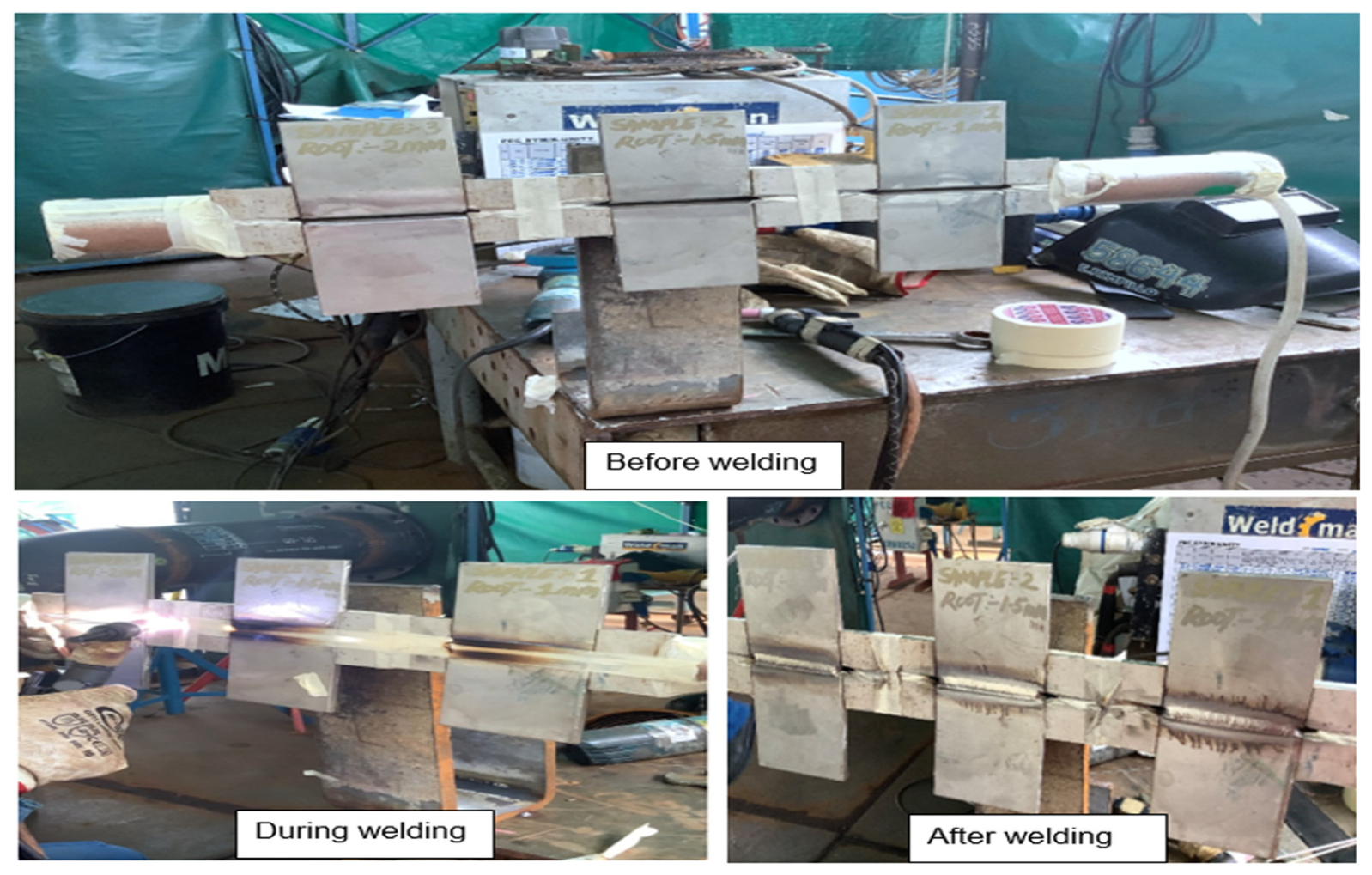
Figure 3.
Profile RT results for samples 4, 5 & 6.
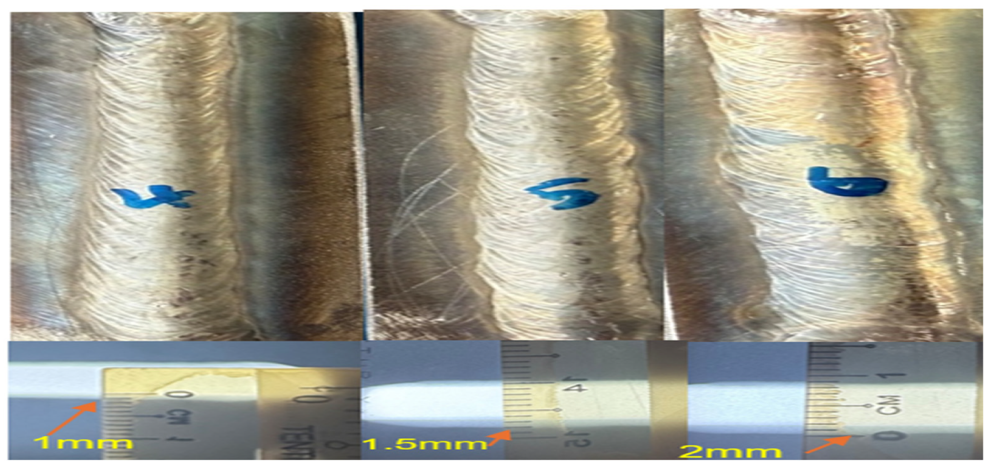
Figure 5.
Pipe sample before and during welding.
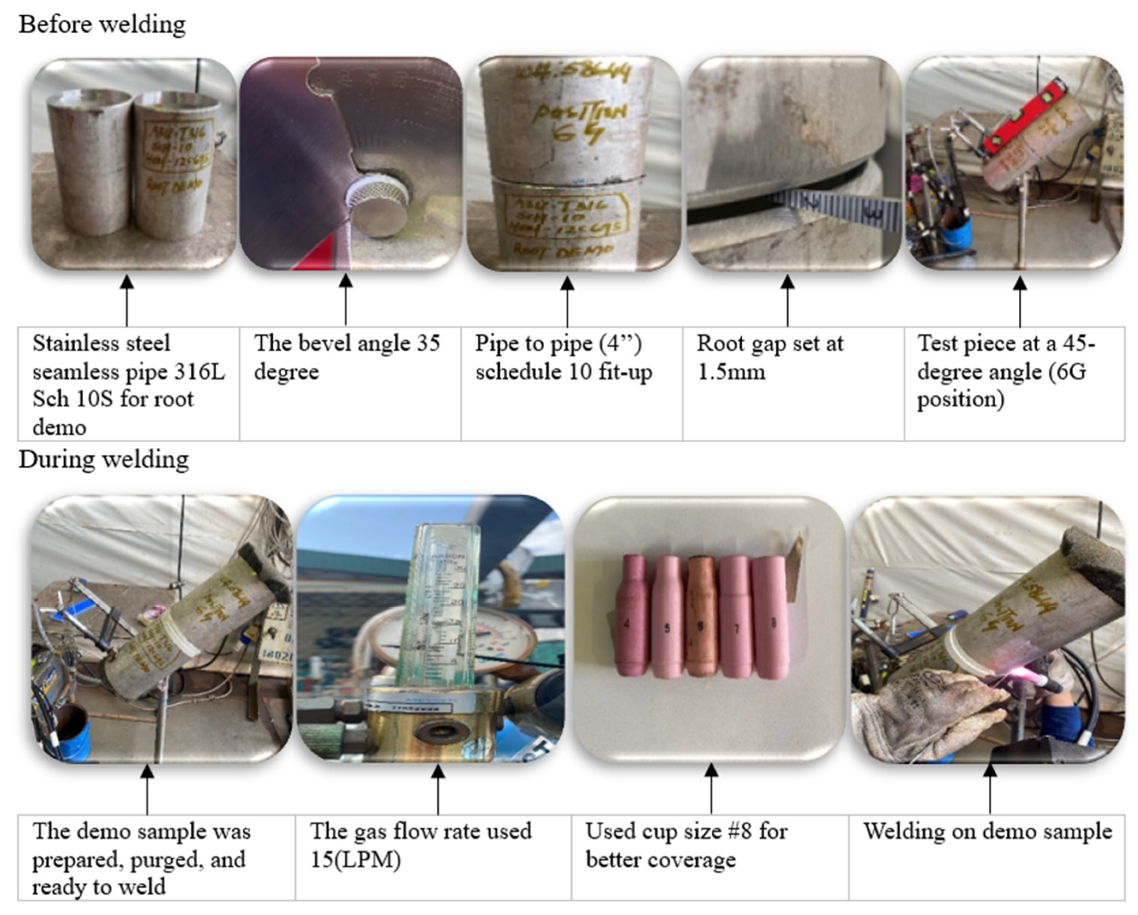
Figure 6.
Visual inspection showing weld protrusion height measurements (<1.5 mm) observed at various circumferential positions: (a) 6 to 9 o’clock, (b) 9 to 12 o’clock, (c) 12 to 3 o’clock, and (d) 3 to 6 o’clock.
Figure 6.
Visual inspection showing weld protrusion height measurements (<1.5 mm) observed at various circumferential positions: (a) 6 to 9 o’clock, (b) 9 to 12 o’clock, (c) 12 to 3 o’clock, and (d) 3 to 6 o’clock.
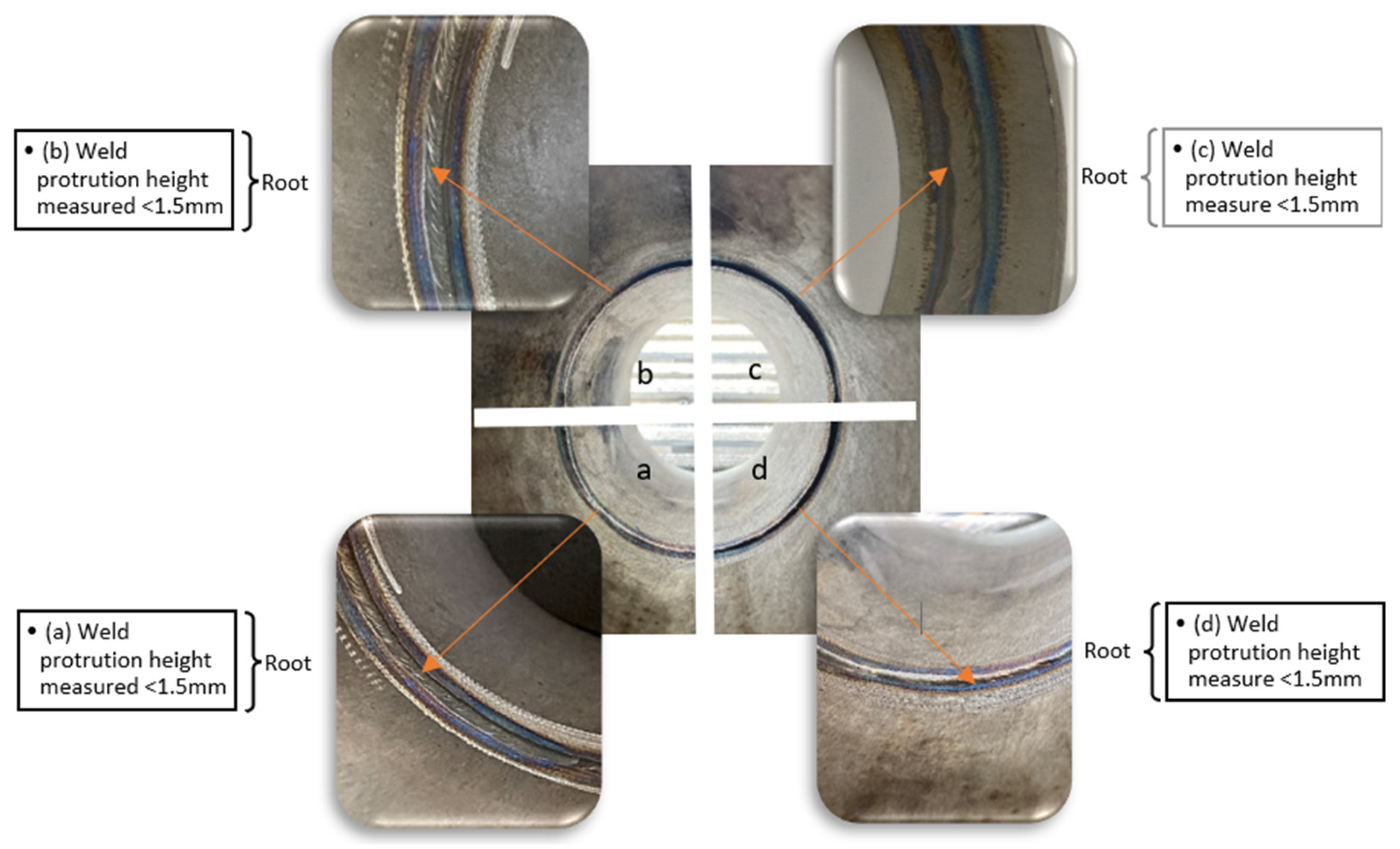
Figure 8.
(a) Shows the joint preparation; (b) shows the Macro sample preparation; (c) shows the macro root measurement; (d) shows the profile RT measurement.
Figure 8.
(a) Shows the joint preparation; (b) shows the Macro sample preparation; (c) shows the macro root measurement; (d) shows the profile RT measurement.
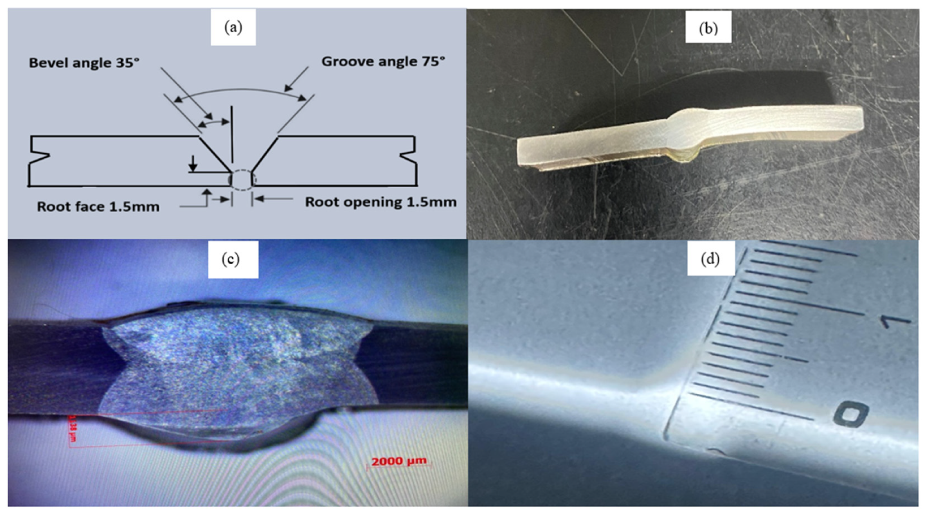
Figure 10.
Main effects plots (corroborated by regression and S/N analysis.
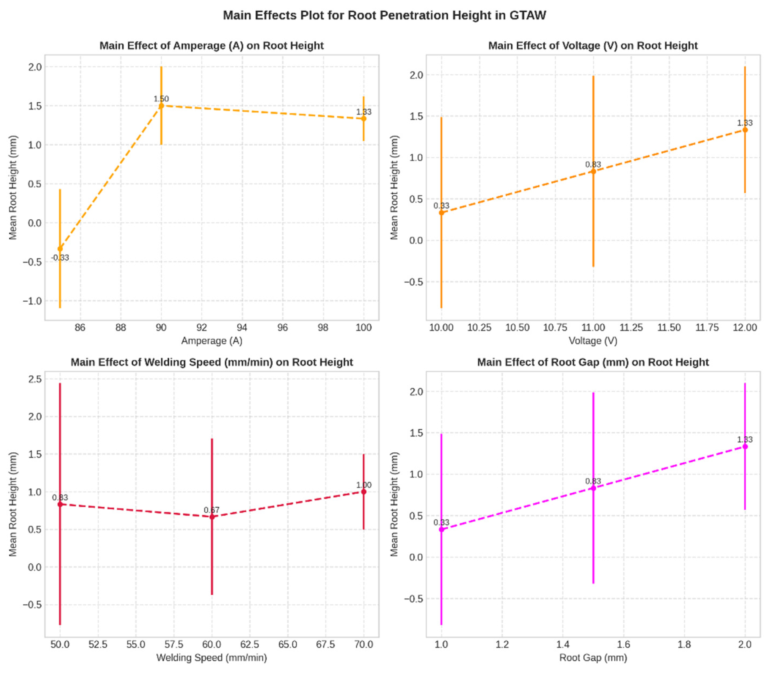
Figure 11.
Main effects plots (corroborated by regression and S/N analysis) for the S/N ratios.
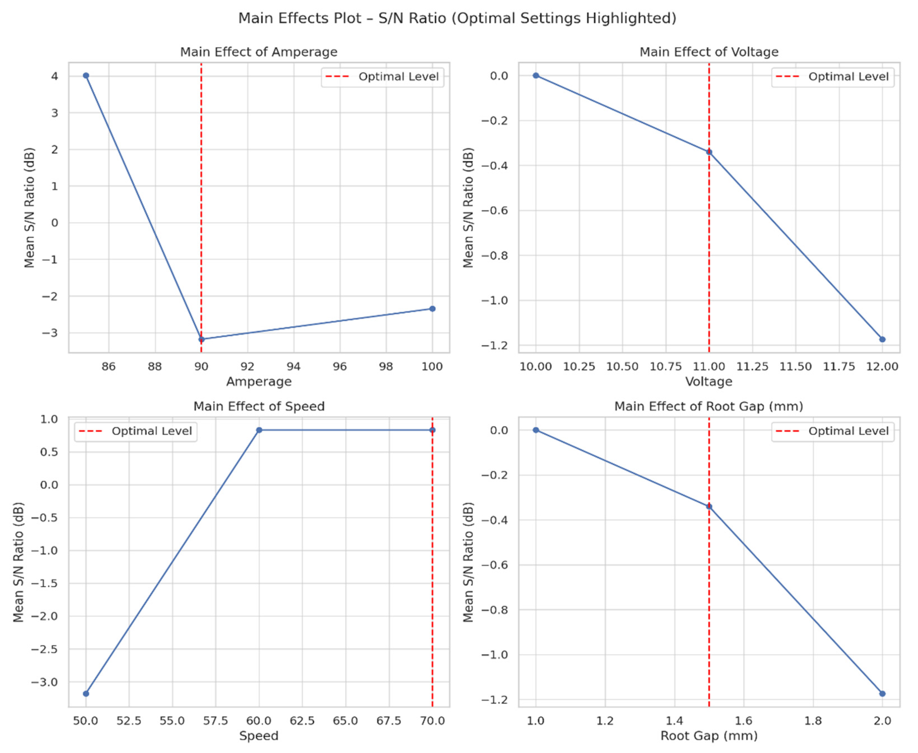
Table 1.
Chemical composition (base and filler material).
| Description | C | Si | Mn | P | S | Cr | Mo | Ni | Cu | N | |
|---|---|---|---|---|---|---|---|---|---|---|---|
| WEL TIG 316L filler wire | 0.02 | 0.45 | 1.55 | 0.025 | 0.008 | 18.15 | 2.57 | 11.33 | 0.08 | 0.07 | |
| Base Material 316L | 0.02 | 0.45 | 1.43 | 0.028 | 0.01 | 16.85 | 2.03 | 10.02 | NA | .036 | |
Table 2.
Welding parameter and test results for 9 test samples.
| Samples | Amp | Vol | Speed | RG | VI | ARPH | Oxi |
|---|---|---|---|---|---|---|---|
| 1 | 85 | 10 | 50 | 1 | 0 | -1.0 mm | 0 |
| 2 | 85 | 11 | 60 | 1.5 | 0 | -0.5 mm | 0 |
| 3 | 85 | 12 | 70 | 2 | 1 | 0.5 mm | 0 |
| 4 | 90 | 10 | 60 | 1 | 1 | 1.0 mm | 1 |
| 5 | 90 | 11 | 70 | 1.5 | 1 | 1.5mm | 1 |
| 6 | 90 | 12 | 50 | 2 | 1 | 2.0mm | 1 |
| 7 | 100 | 10 | 70 | 1 | 1 | 1.0mm | 0 |
| 8 | 100 | 11 | 50 | 1.5 | 1 | 1.5mm | 0 |
| 9 | 100 | 12 | 60 | 2 | 1 | 1.5mm | 0 |
Note: 0 = Bad; 1 = Good; Amp = amperage; Vol = voltage; VI = visual inspection; RG= root gap; ARPH= actual root penetration height; Oxi= oxidation;.
Table 4.
ANOVA Summary for Root Penetration Height.
| sum_sq | df | F | PR(>F) | % Contribution | |
|---|---|---|---|---|---|
| (Amperage) | 6.166666667 | 2 | 37 | 0.026315789 | 64.9122807 |
| (Voltage) | 1.5 | 2 | 9 | 0.1 | 15.78947368 |
| (Speed) | 0.166666667 | 2 | 1 | 0.5 | 1.754385965 |
| (“Root Gap”) | 1.5 | 2 | 9 | 0.1 | 15.78947368 |
| Residual | 0.166666667 | 2 | 1.754385965 |
Disclaimer/Publisher’s Note: The statements, opinions and data contained in all publications are solely those of the individual author(s) and contributor(s) and not of MDPI and/or the editor(s). MDPI and/or the editor(s) disclaim responsibility for any injury to people or property resulting from any ideas, methods, instructions or products referred to in the content. |
© 2025 by the authors. Licensee MDPI, Basel, Switzerland. This article is an open access article distributed under the terms and conditions of the Creative Commons Attribution (CC BY) license (http://creativecommons.org/licenses/by/4.0/).
Copyright: This open access article is published under a Creative Commons CC BY 4.0 license, which permit the free download, distribution, and reuse, provided that the author and preprint are cited in any reuse.


