Submitted:
11 April 2025
Posted:
11 April 2025
You are already at the latest version
Abstract
A novel photonic-aided approach for generating flexible frequency hopping (FH) signals using optical comb filtering (OCF) is proposed and investigated. Wavelength selection, controlled by an intermediate-frequency (IF) signal, is achieved by leveraging the arithmetic progression of frequency differences between the OCF passband and the OFC comb lines. After optical heterodyne mixing of the selected wavelengths with the IF-FH signals, ultra-wideband and flexible FH signals are generated. Theoretical analysis and simulations are carried out to demonstrate the generation of 5-level, 10-level, and 25-level stepped frequency and Costas FH signals, as well as more complex signals like a 30 GHz LFM signal and a 24 GHz sinusoidal chirped signal. The effects of laser frequency offset and system parameter selection are also discussed. This approach, offering wide bandwidth, flexible tuning, good stability, and integration potential, is promising for applications in cognitive radio, modern radar systems, and electronic warfare.
Keywords:
microwave photonics
; frequency hopping
; optical comb filtering
1. Introduction
The proliferation of frequency-using devices has exacerbated the scarcity of spectral resources. Consequently, modern radar and wireless communication systems require extensive, rapid, and flexible frequency tuning capabilities to mitigate frequency conflicts [1,2]. Additionally, the increasing demands for secure data transmission and anti-jamming have highlighted the growing importance of frequency hopping (FH) systems [3,4,5,6]. However, due to the inherent limitations in the operational bandwidth of electrical technologies, frequency hopping systems based on electrical frequency synthesis techniques face significant challenges in achieving real-time frequency hopping over a range of tens of gigahertz (GHz). Photonic-based technologies, characterized by their large operational bandwidth, low loss, immunity to electromagnetic interference, flexibility, and reconfigurability [7], have emerged as a promising alternative.
In recent years, various schemes for generating FH signals based on photonic technologies have been reported. In [8,9,10,11,12,13,14,15,16], FH signals with large frequency intervals and high hopping speeds are achieved through optical frequency switching, which is accomplished by adjusting the bias voltage of the Mach-Zehnder modulator (MZM) [8,9,10,11], the polarization direction in the polarization modulator (PolM) [12,13,14], and the passband of the optical filter [15,16]. Although these schemes realize wideband frequency hopping, the limited number of hopping points (typically 2 points) is insufficient to meet the flexibility requirements in practical scenarios.In [17], a 4-level FH signal is generated by combining polarization direction control and bias control; however, further expansion of the FH points remains challenging. In [18,19], In [18,19], optical tunable filters based on micro-ring resonators (MRR) or Mach-Zehnder interferometers (MZI) are used to select the desired wavelengths of an optical frequency comb (OFC), thereby controlling the frequency of the output microwave signal. The FH frequency points in this method are determined by the number and spacing of the OFC comb lines, making it difficult to achieve flexible tuning to any arbitrary frequency within a given bandwidth. Additionally, increasing the number of FH points leads to greater complexity in the tunable optical filter, resulting in higher losses and reduced stability. In [20], a flexible FH generator based on dynamic control of an optically injected semiconductor is proposed. Despite this, the high spontaneous emission noise in the laser source results in poor frequency accuracy of the FH signals. In reference [21], ultra-low phase noise FH signals are generated using a coupled optoelectronic oscillator (OEO). Nonetheless, the extended frequency switching times in the system limit the FH speed of the generated signals. In [22], the flexibility of electrical frequency hopping and the large bandwidth of optical wavelength selection are integrated. Phase selection and wavelength switching on dual coherent OFCs control the frequency interval between the intermediate-frequency FH signal's optical sidebands and the optical local oscillator, enabling wideband and flexible FH signal generation. However, the use of optical switches restricts the FH speed.
In this work, optical comb filtering is applied to the optical sidebands of an OFC, enabling wavelength selection without the need for active optical tunable filters or optical switches. This approach offers improved stability and a simpler engineering implementation. After optical heterodyne mixing of the selected wavelengths with electro-optically modulated intermediate-frequency (IF) FH signals, ultra-wideband and flexible FH signals are obtained. Simulations verify the generation of 5-level, 10-level, and 25-level frequency-stepped and Costas sequence-controlled FH signals, achieving a maximum FH bandwidth of 30 GHz and an FH speed of 100 MHz. Additionally, 30 GHz linear frequency modulation (LFM) signals and 24 GHz sinusoidal chirped signals are successfully generated, demonstrating the flexibility of the proposed scheme. The system also exhibits good reconfigurability, as its FH bandwidth can be increased by increasing the number of the OFC comb lines without altering the system architecture.
2. Theory and Principle
Figure 1 (a) presents the architecture of the proposed photonic-aid flexible frequency-hopping (FH) signals generator, which is composed of an optical frequency comb (OFC) generator, a band pass optical filter (OF), an optical comb filter (OCF), a pair of dual-parallel Mach-Zehnder modulator, a pair of 90°hybrid and a photodetetor (PD) . Assume that the emitted optical signal of the OFC source can be expressed as
where Ein, n and FSR1 is the amplitude, index and free spectrum range (FSR) of OFC. f0 represents the frequency of the first wavelength of the optical frequency comb (OFC). The total number of the wavelength of the OFC is N. In the upper brunch, the OFC is applied to DP-MZM1 and carrier suppressed right single sideband (CS-RSSB) modulated by a intermediate frequency (IF) signal RF1 provided by MSG1. The obtained signal can be given by
Where fRF1 is the frequency of the signal emitted from MSG1, mDP1 is the modulation index of DP-MZM1. Jn(·) denotes the Bessel function of the first kind. The optical signal outputted by DP-MZM1 is then sent into the optical comb filter (OCF) to perform wavelength selection. The OCF is an narrow band optical periodic filter with a FSR of FSR2. The central frequency of the n-th pass band of the OCF is expressed as
In which f1 is the central frequency of the first pass band of the OCF. Let Δf to be the frequency difference between FSR1 and FSR2, then (2) can be re-written as
As shown in Figure 1 (d), by setting fRF1 to be (n-1)Δf +f1-f0, only the +1-st order sideband of the n-th wavelength of the OFC falls in the pass band of the OCF. Consequently, the filtered signal at the output of OCF is given by
Therefore, the broad band wavelength selection controlled by an IF signal can be achieved. As illustrated in Figure 1 (c) and (e), the first wavelength extracted by the OF is carrier suppressed left single-sideband (CS-LSSB) modulated by the IF signal RF2 generated by MSG2 at DP-MZM2. The resultant signal can be expressed as
In which, Where fRF2 is the frequency of the signal emitted from MSG2, mDP2 is the modulation index of DP-MZM2. The optical signal EDP1(t) and EDP2(t) is combined and then sent into PD. After optical to electrical conversion, the photocurrent at the output of PD is given by
As can be observed in (9), the frequency of iPD2(t) is defined by fRF1 and fRF2. By setting fRF1 to be (n-1)Δf +f1-f0, iPD2(t) is coarse converted to the frequency range of (fOCF-f0+(l-1)·FSR2, fOCF-f0+l·FSR2). Tuning fRF2 from 0 to FSR2, a fine conversion can be achieved. Thus, by providing two IF FH signal from MSG1 and MSG2, the ultra-wide band flexible FH signal generation covering the frequency range of (fOCF-f0, fOCF-f0+N·FSR2) can be achieved.
3. Simulation Results and Discussion
A simulation work base on the structure shown in Figure 1 (a) is carried out through “Optisystem” to verify the theoretical analysis. The parameters setting are presented in Table 1.
3.1. Optical Spectra Performance
First of all, the optical spectra of each devices in the process of flexible FH signals generation are extracted and displayed at Figure 2. By setting the frequency of the first comb f0 and FSR1 to be 191.1 THz and 5.8 GHz, a five-wavelength OFC is generated as shown in Figure 2 (a). At for the OCF, f1 and FSR2 are setting to be 191.1004 THz and 6 GHz, respectively. A 600 MHz single tone signal generated by MSG1 is sent to DP-MZM1. The resultant spectrum is shown in Figure 2 (b). Due to limited extinction ratio, the SSR of the generated signal is only 15.71 dB. Thanks to the narrow bandwidth of the OCF, only the +1-st order sideband of the second wavelength can be remained. As can be observed in zoomed spectra near the first, second and third wavelength is presented in Figure 2 (c), (d) and (e), the +1-st order sideband near the second wavelength falls in the pass band of the OCF with the else out of it. Thus, the wavelength selection is successfully implemented. On the other hand, another single-tone signal provided by MSG2 is applied to DP-MZM2, and the generated optical spectum is shown in Figure 2 (f). Since the carrier can not be well suppressed, an extra optical filter is utilized to extract the -1-st order sideband. The filtered spectrum is given in Figure 2 (g). In Figure 2 (h), the output of OCF and OF2 are combined. After optical to electrical conversion, an wide-band flexible FH signal can be obtained.
3.2. Demonstration of Wavelength Selection
To investigate the performance of wavelength selection, the driving RF signal provide by MSG1 is tuned from 0.4 GHz to 1.2 GHz with a step of 0.2 GHz as shown in Figure 3 (b). Controlled by the driving signals, the optical spectra of the selected wavelength are shown in Fig (a). Obviously, the wavelengths located at 193.1004 THz, 193.1064 THz, 193.1124 THz, 193.1184 THz and 193.1244 THz are selected with an average SSR higher than 38 dB indicating a high signal quality without interference of spurious components. Therefore, wavelength selection over a wide range of 30 GHz controlled by an IF signal under 1.2 GHz is achieved.
3.3. Demonstration of Flexible FH Signal Generation
The performance of FH signals generation is demonstrated. In this section, a 5-level, a 10-level and a 25-level stepped frequency signals with a period of 2.5 μs are generated. The frequency hopping intervals of the obtained signals are 6 GHz, 3GHz and 1.2 GHz. After Garbor transformation, the corresponding time-frequency diagrams are shown in Figure 4 (a), (b) and (c). As can be observed, the FH signals exhibit concentrated energy at each frequency point, with no additional spurious frequency components present. In terms of the temporal waveforms of the generated signals shown in Figure 4 (d), (e) and (f), slight periodic envelope fluctuations exist, particularly in Figure 4 (e) and (f). This is because the broadband optical bandpass filter OF2, used to suppress the optical carrier, has a non-flat passband response. Consequently, when the output signal frequency from MSG2 changes, the amplitude of the generated signal varies.
In order to further investigate the flexibility of the proposed scheme, the generation of FH signals with random frequency order are implemented. Table 2 describes the parameter settings used to generate random FH signals. Here we employ Costas sequences with lengths 5, 10, and 25 to control the frequency order. The time-frequency diagrams of the generated signal is plotted in Figure 5 (a), (b) and (c), the energy distributions are clear and consistent well with the theoretical analysis: 5, 10 and 25 frequencies with minimum frequency deviation 6GHz, 3GHz and 1.2GHz exist in the diagrams and their frequency orders are in agreement with the ordering in Table. 2. As can be found in the corresponding temporal waveforms in Figure 5 (c), (d) and (e), the average amplitude is around 0.05 V. The fluctuations in the waveform envelope are within 20%.
Moreover, the proposed scheme is capable of generating more complex frequency-agile signals with large bandwidth. As illustrated in Figure 6 (a), by incrementally increasing the output frequency of MSG1 from 0.4 GHz to 1.2 GHz in 0.2 GHz steps, and with MSG2 providing a 6 GHz bandwidth LFM signal, a wide-band LFM signal with a bandwidth up to 30GHz is successfully generated. In Figure 6 (b) a 24 GHz non-linearly chirped signal can also be obtained. The chirp shape of the signal is a smooth sinusoidal waveform with a period of 2.5 μs. The auto-correlation calculation results of the LFM signal and sinusoidal chirped signal are presented in Figure 6 (c) and (d), showing two sharp and narrow peaks. The full width at half maximum (FWHM) of the two peaks are 0.016 ns and 0.02 ns, respectively, corresponding to pulse compression ratios of 156,250 and 125,000, indicating excellent pulse compression performance. This suggests that the proposed scheme holds promising application prospects in high-resolution radar systems.
3.4. Effect of Frequency Off-Set Between OFC and OCF
In practice, non-ideal factors such as temperature variations and manufacturing limitation can lead to a time-varying frequency off-set between the OFC and the pass band of OCF, thereby affecting the quality of the generated FH signals. Setting the output frequency of MSG1 to be 0.4 GHz, then the +1 order sideband of the first wavelength of the OFC will be selected after the OCF theoretically. As shown in Figure 7 (a-i), when there is no frequency off-set, the desired sideband are precisely centered within the pass band of the OCF. At this point, the filtered optical sideband exhibit maximum power, as illustrated in Figure (b-i), where the resulting spectrum achieves a SSR of 41.82 dB.When the OFC source has a 100 MHz frequency offset, as shown in Figure (a-ii), the desired optical sideband appear at the edge of the OCF passband, leading to a reduction in the power of the sideband in the OCF output signal. As seen in Figure (b-ii), the SSR of the output optical signal decreases to 9.08 dB. To further investigate the effect of frequency off-set, frequency off-set deviations are added to the simulation to monitor the SSR variation of the selected sideband. Figure 7 (c) presents the recorded results. As evident from from the plot, when the frequency offset is less than 40 MHz, the OSSR of the selected wavelength remains above 40 dB. If the offset exceeds 40 MHz, the OSSR drops significantly, falling below 10 dB at 100 MHz. This is due to the 100 MHz passband width of the OCF used in the simulation. When the frequency offset exceeds 40 MHz, the desired wavelength is positioned at the edge of the passband, resulting in a significant degradation of the OSSR of the generated signal. To mitigate the effects of frequency offset, a narrow-linewidth stable laser can be used to provide an OFC source with sufficiently low frequency drift. Additionally, increasing the passband width of the OCF can enhance tolerance to frequency offsets. In this case, the frequency difference between FSR1 and FSR2 should at least higher than the bandwith of the pass band of the OCF. However, this approach may impact the frequency range of the generated signals and impose higher bandwidth requirements on the MSG. The required operating bandwidth of the RF source in practical applications and the maximum frequency range of the generated signals by the system will be investigated in the subsequent sections.
3.5. Analysis of System Performance Limits and Parameter Selection
In the simulation, the number of optical comb lines N of the OFC was set to 5, with the free FSRs of the OCF and OFC configured to 6 GHz and 5.8 GHz, respectively. Consequently, the FH signals generated are confined to a frequency range of 30 GHz. In practical applications, the maximum frequency-hopping range can be expanded by increasing N, and it is also restricted by the values of FSR1 and FSR2.
According to the analysis in the principle section, the key to wavelength selection lies in matching the frequency of the IF signal output by the MSG with the frequency difference between the OFC comb lines and the center frequency of the OCF passband. Then, the frequency difference between the n-th OFC comb and the center frequency of the n-th OCF passband fd-n can be given as
When fd-n exceeds FSR1, the frequency difference between the center frequency of the n-th passband and the frequency of the (n−1)-th comb line, fd-n−FSR1, can cause crosstalk with another frequency difference fd-n’. This results in undesired wavelengths appearing within the passband. Figure 8 gives an example of an undesired wavelength selection results. Here, we set FSR1, FSR2 and f1-f0 to be 5.6 GHz, 6 GHz and 0.4 GHz. Mathematically, there is an ambiguity between fd-15-FSR1 and fd-1. As can be observed in Figure 8, when the output frequency of MSG1 is 0.4 GHz, both the +1-st order sideband of the first and 15-th comb line exists with high power. The SSR is only 5.42 dB. If ignore the effect of the 15-th comb line, the SSR is up to 39.97 dB.
Thus, to ensure the effectiveness of wavelength selection, the maximum number of OFC comb lines N should satisfy:
As mentioned in the principle section, the frequency tunning range of the signals output by MSG2 should reach FSR2, meaning that the operational bandwidth of MSG2 should at least be FSR2. Under this premise, the maximum frequency tunning range Bmax of the proposed generator can be expressed as
In practical engineering applications, the signal generation system frequently does not necessitate a frequency tuning range as extensive as Bmax. Consequently, the number of OFC comb lines N can be chosen according to the specific requirements. Correspondingly, the operational bandwidth of MSG1 should be broader than N·Δf. To achieve lower costs, it is generally desirable to minimize the real-time operating bandwidth requirements of the RF signal source for the system. This implies that, while ensuring the operating frequency range of the flexible FH signal generator meets the requirements, both FSR2 and N·Δf should be minimized. However, a smaller FSR for the OCF increases the fabrication complexity and cost. Additionally, the value of Δf must also meet the system's tolerance requirements for laser source frequency offset. Therefore, the selection of various parameters for the proposed scheme can be described by the following optimization problem:
In this optimization problem, the objective is to minimize both FSR2 and N·Δf to achieve lower costs and simpler fabrication. The constraints ensure that:
- FSR2 is not smaller than the minimum feasible FSR, FSRmanu considering fabrication complexity and cost.
- N is at most Nmax, the maximum number of comb lines for effective wavelength selection.
- N·FSR2 meets the required frequency tuning range B.
- Δf is at least the fprotect, the maximum number of comb lines for effective wavelength selection.
3.6. Comparison with the Related Work
Based on the analysis above, the comparison of this work with other reported multi-level FH signal generation schemes is shown in Table 3. Hopping level, operational bandwidth, frequency tunability and limitations are evaluated and summarized. Thanks to the periodic characteristics of OFC and OCF, the operational bandwidth of the proposed generator can be easily extended to tens of GHz. Simultaneously, with the precise combination of electrical frequency hopping signal generation, it exhibits flexible frequency tuning performance and good frequency accuracy. Noteworthy, the proposed scheme adopts OCF as a passive element, which demonstrates superior stability compared to tunable filters. Furthermore, the absence of optical switch components eliminates the introduction of additional frequency switching time. The design does not require the use of long optical fiber loops, thereby presenting a more promising prospect for integration. This characteristic facilitates a reduction in both volume and power consumption, while simultaneously improving stability.
4. Conclusion
A photonic-aid flexible FH signal generator based on optical comb filtering is proposed and investigated. In the simulation work, 5-level, 10-level and 25-level stepped and Costas sequence controlled FH signals are obtained. The frequency hopping bandwidth and hopping rate achieve 30 GHz and 0.1 GHz, respectively. The generation of more complex frequency agile signal including a 30 GHz LFM signal and a 24 GHz sinusoidal chirped signal are achieved. Besides, the frequency hopping bandwidth can be extended by increasing the number of optical comb lines in the OFC. The effects of laser frequency offset and the selection of system parameters have been analyzed. Methods to minimize the bandwidth requirements of the RF signal source, while still satisfying application demands, have been presented. The proposed scheme, offering a wide operational bandwidth, flexible frequency tuning performance, good stability, and promising integration potential, is expected to find applications in cognitive radio and modern radar systems.
Author Contributions
Supervision, S.Z.; writing—original draft preparation, Y.Z.;writing—review and editing, X.L., G.W, R.W, Z.Z. All authors have read and agreed to the published version of the manuscript.
Funding
This research received no external funding.
Institutional Review Board Statement
This research received no external funding
Informed Consent Statement
This research received no external funding
Data Availability Statement
Not applicable.
Conflicts of Interest
The authors declare no conflicts of interest.
References
- Ghelfi, P.; Laghezza, F.; Scotti, F.; et al. A Fully Photonics-Based Coherent Radar System. Nature 2014, 507, 341–345. [Google Scholar] [CrossRef] [PubMed]
- Romashov, V.V.; et al. Wide-Band Hybrid Frequency Synthesizer with Improved Noise Performance. In Proceedings of the 2018 Moscow Workshop on Electronic and Networking Technologies (MWENT), Moscow, Russia, 15-18 May 2018; pp. 1–4. [Google Scholar]
- Chen, R.; Li, Z.; Shi, J.; et al. High Secure Sequence Design in Frequency Hopping Communications. China Commun. 2019, 16, 139–150. [Google Scholar]
- Skolnik, M. Radar Handbook; McGraw-Hill: New York, NY, USA, 2008. [Google Scholar]
- Simon, M.K.; Omura, J.K.; Scholtz, R.A.; et al. Spread Spectrum Communications Handbook; McGraw-Hill: New York, NY, USA, 1994. [Google Scholar]
- Neri, F. Introduction to Electronic Defense Systems; 3rd ed.; Artech: Norwood, MA, USA, 2018.
- Liu, Q.; Fok, M.P. Ultrafast and Wideband Microwave Photonic Frequency-Hopping Systems: A Review. Appl. Sci. 2020, 10, 521–538. [Google Scholar] [CrossRef]
- Feng, X.; Yan, L.; Li, P.; et al. Photonic Approach for Generation and Fast Switching of Binary Digitally Modulated RF Signals. IEEE Photonics J. 2020, 12, 1–8. [Google Scholar] [CrossRef]
- Lei, M.; Zheng, Z.; Song, C.; et al. Equivalent Photonic Switch for Microwave Frequency Shift Keying Signal Generation. Opt. Lett. 2019, 44, 3138–3141. [Google Scholar] [CrossRef] [PubMed]
- Chen, Y. High-Speed and Wideband Frequency-Hopping Microwave Signal Generation via Switching the Bias Point of an Optical Modulator. IEEE Photonics J. 2018, 10, 1–7. [Google Scholar] [CrossRef]
- Cao, P.; Hu, X.; Zhang, L.; et al. Photonic Generation of Microwave Frequency Shift Keying Signal Using a Single-Drive Mach-Zehnder Modulator. Opt. Express 2014, 22, 14433. [Google Scholar] [CrossRef] [PubMed]
- Huang, L.; Wang, P.; Xiang, P.; et al. Photonic Generation of Microwave Frequency Shift Keying Signals. IEEE Photonics Technol. Lett. 2016, 28, 1928–1931. [Google Scholar] [CrossRef]
- Li, X.; Zhao, S.; Zhang, K.; et al. Photonic Generation of Microwave Binary Digital Modulation Signal with Format Agility and Parameter Tunability. Opt. Commun. 2018, 429, 106–111. [Google Scholar] [CrossRef]
- Ye, J.; Yan, L.; Wang, H.; et al. Photonic Generation of Microwave Frequency Shift Keying Signal Using a Polarization Maintaining FBG. IEEE Photonics J. 2018, 10, 1–8. [Google Scholar] [CrossRef]
- Xie, Y.; Zhuang, L.; Jiao, P.; Dai, D. Sub-Nanosecond-Speed Frequency Reconfigurable Photonic Radio Frequency Switch Using a Silicon Modulator. Photon. Res. 2020, 8, 852–857. [Google Scholar] [CrossRef]
- Jiang, H.; Yan, L.; Pan, Y.; et al. Microwave Photonic Comb Filter with Ultra-Fast Tunability. Opt. Lett. 2015, 40, 4895–4898. [Google Scholar] [CrossRef] [PubMed]
- Feng, X.; Yan, L.; Jiang, H.; et al. Photonic Generation of Multilevel Frequency-Hopping Microwave Signal. IEEE Photonics J. 2019, 11, 1–7. [Google Scholar] [CrossRef]
- Zhou, F.; Wang, X.; Yan, S.; et al. Frequency-Hopping Microwave Generation with a Large Time-Bandwidth Product. IEEE Photon. J. 2018, 10, 1–9. [Google Scholar] [CrossRef]
- Wang, G.; et al. High-Speed and Wideband Multilevel Frequency-Hopping Microwave Signal Generation Based on a Sagnac Loop. Results Phys. 2023, 52, 106807. [Google Scholar] [CrossRef]
- Zhou, P.; Zhang, F.; Ye, X.; et al. Flexible Frequency-Hopping Microwave Generation by Dynamic Control of Optically Injected Semiconductor Laser. IEEE Photon. J. 2016, 8, 1–9. [Google Scholar] [CrossRef]
- Liu, H.; Guo, M.; Zhang, T.; et al. Ultralow-Phase-Noise and Broadband Frequency-Hopping Coupled Optoelectronic Oscillator Under Quiet Point Operation. Photonics Res. 2024, 12, 1785–1793. [Google Scholar] [CrossRef]
- Bochao, K.; et al. Wideband Microwave Frequency-Hopping Signal Generation Technology Based on Coherent Double Optical Comb. J. Lightwave Technol. 2024, 42, 7634–7642. [Google Scholar] [CrossRef]
Figure 1.
Schematic diagram of the proposed flexible frequency-hopping signals generator. OFC, optical frequency comb; OF, optical filter; DP-MZM, dual parallel Mach-Zehnder modulator; OCF, optical comb filter; PD, photodetector.
Figure 1.
Schematic diagram of the proposed flexible frequency-hopping signals generator. OFC, optical frequency comb; OF, optical filter; DP-MZM, dual parallel Mach-Zehnder modulator; OCF, optical comb filter; PD, photodetector.
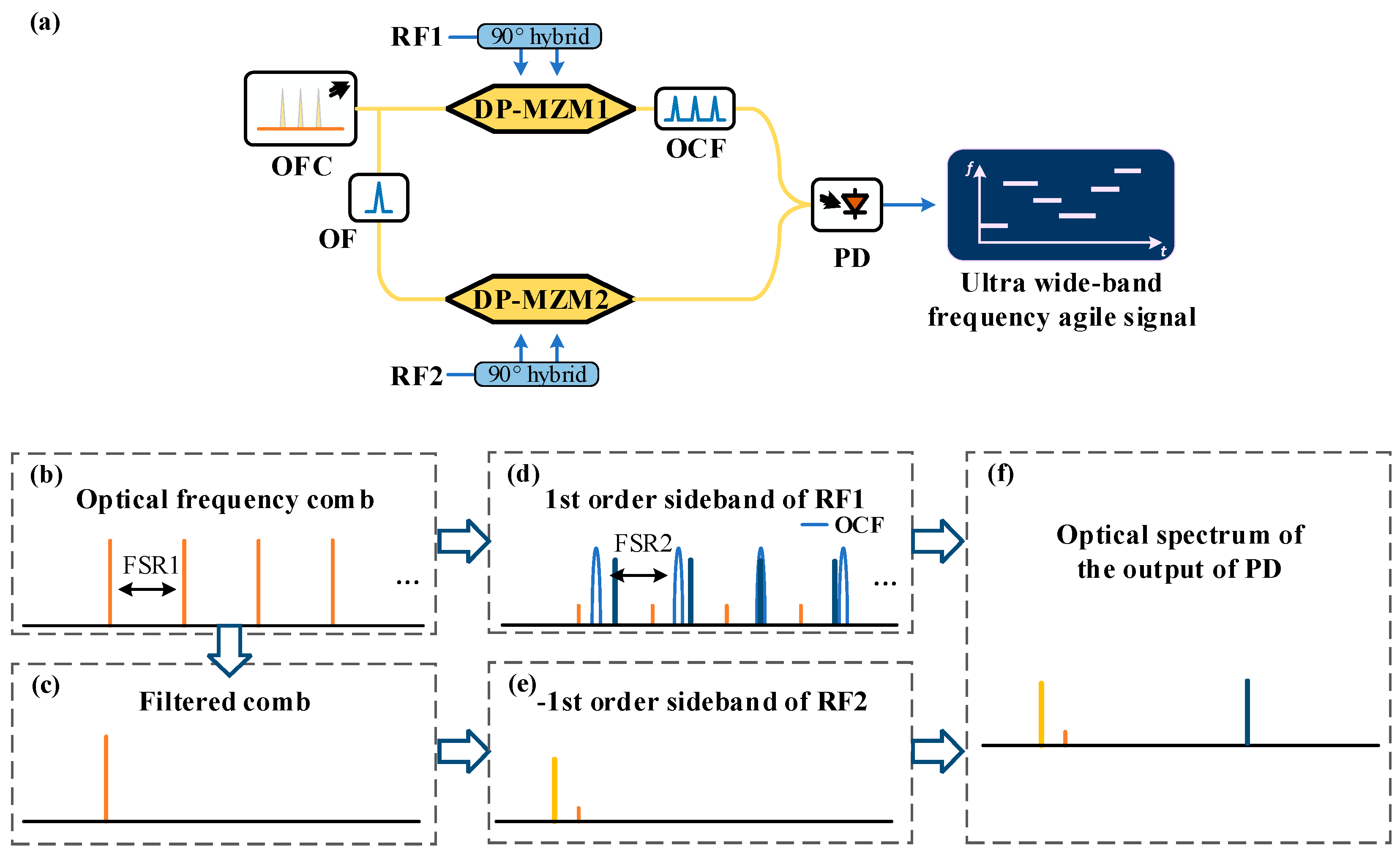
Figure 2.
The optical spectra at the output of (a) OFC generator, and (b) DP-MZM1. The zoomed optical spectra of DP-MZM1 near the (c) first, (d) second and (e) third optical comb. The optical spectra at the output of DP-MZM2 (f) before and (g) after optical filtering. (h) The optical spectrum of the signal inputted to PD.
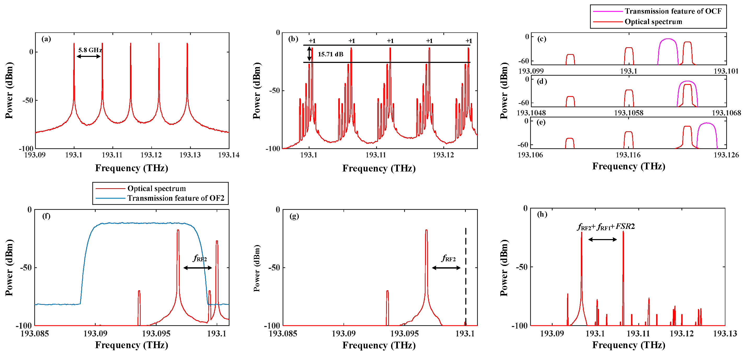
Figure 3.
(a) The optical spectrum of the selected wavelength and (b) the RF spectrum of the driving signal.
Figure 3.
(a) The optical spectrum of the selected wavelength and (b) the RF spectrum of the driving signal.
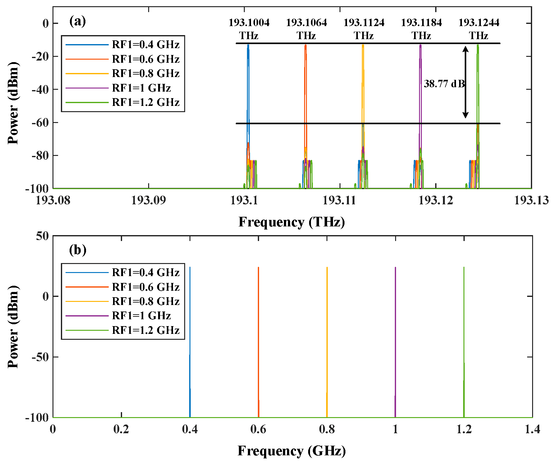
Figure 4.
The time-frequency diagram of the generated (a) 5-level, (b) 10-level, (c) 25-level stepped frequency signal and their temporal waveforms (d), (e) and (f).
Figure 4.
The time-frequency diagram of the generated (a) 5-level, (b) 10-level, (c) 25-level stepped frequency signal and their temporal waveforms (d), (e) and (f).
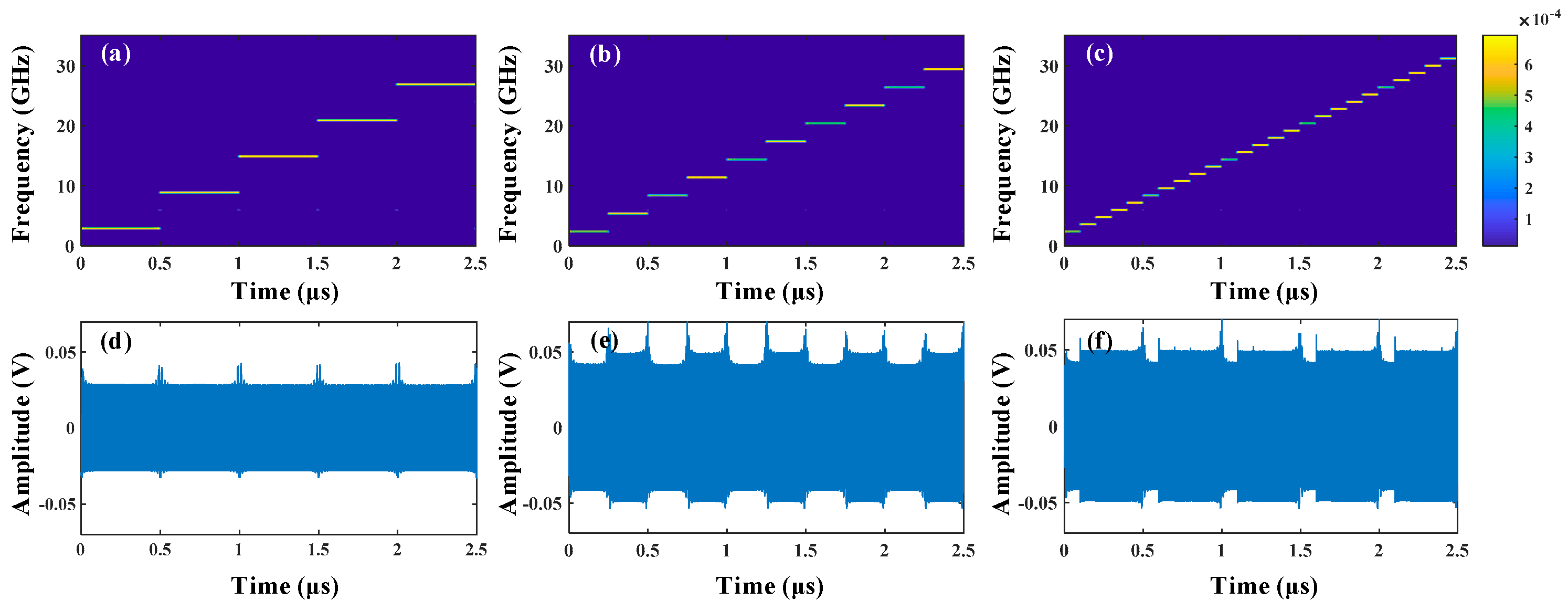
Figure 5.
(a)-(c) The time-frequency diagrams of the FH signals controlled by different costas codes and (d-f) their temporal waveforms.
Figure 5.
(a)-(c) The time-frequency diagrams of the FH signals controlled by different costas codes and (d-f) their temporal waveforms.
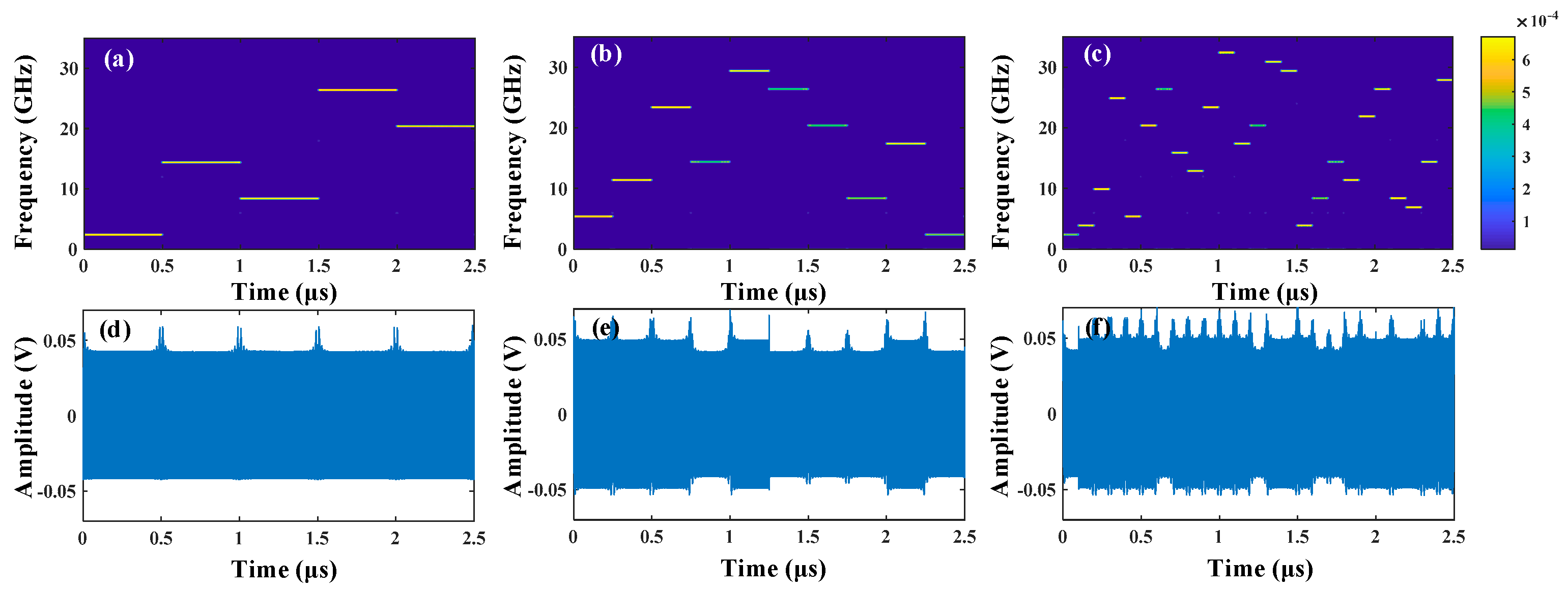
Figure 6.
Time-frequency diagrams of the generated (a) LFM signal and (b) sinusoidal chirped signal and their auto-correlation calculation results (c), (d).
Figure 6.
Time-frequency diagrams of the generated (a) LFM signal and (b) sinusoidal chirped signal and their auto-correlation calculation results (c), (d).
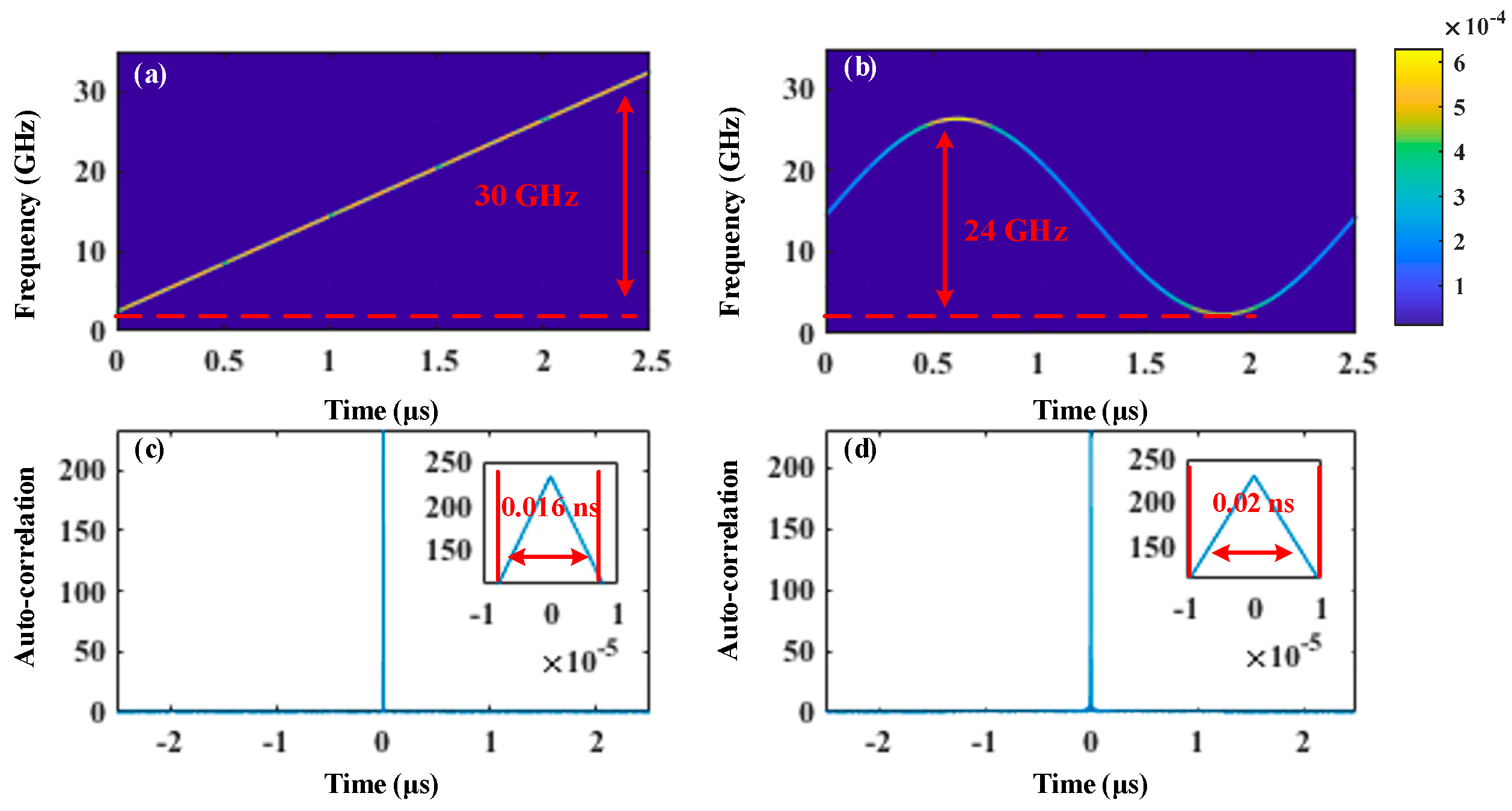
Figure 7.
(a-i) The zoomed optical spectra near the first wavelength without frequency off-set and (a-ii) with a 100 MHz off-set. (b-i) The optical spectra after the OCF without frequency off-set and (b-ii) with a 100 MHz off-set. (c) The SSR versus frequency off-set curve of the filtered signal.
Figure 7.
(a-i) The zoomed optical spectra near the first wavelength without frequency off-set and (a-ii) with a 100 MHz off-set. (b-i) The optical spectra after the OCF without frequency off-set and (b-ii) with a 100 MHz off-set. (c) The SSR versus frequency off-set curve of the filtered signal.
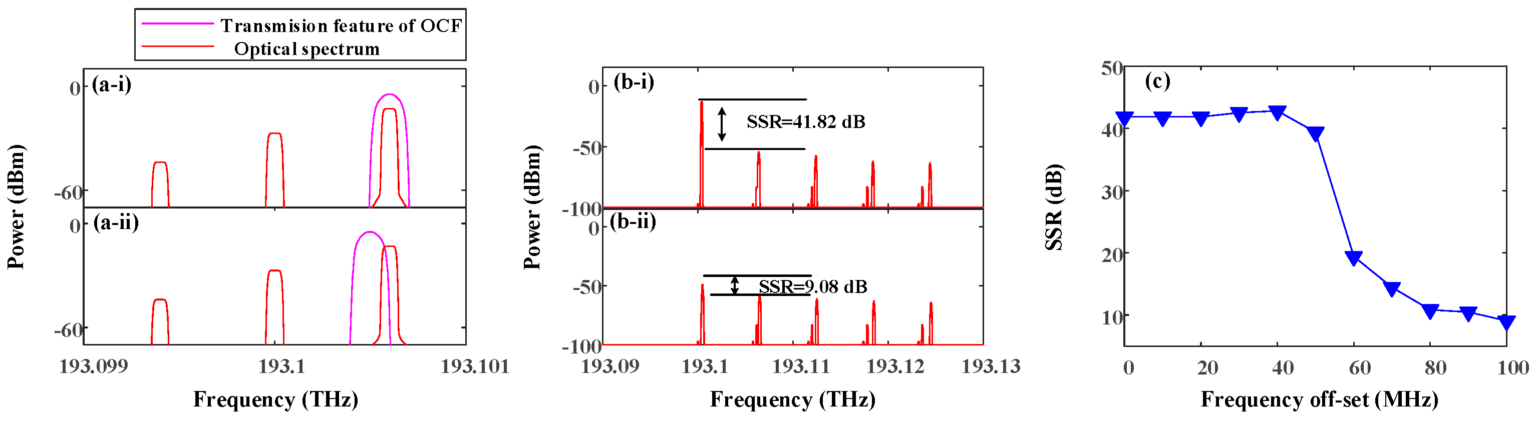
Figure 8.
The optical spectrum of the undesired wavelength selection result.
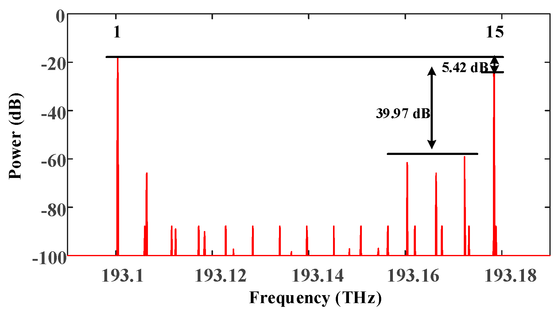

Table 1.
The parameters setting of the devices in the simulation.
| Devices | Parameters |
|---|---|
| OFC generator | Number of combs: 5 Initial frequency: 191.1 THz FSR: 5.8 GHz Linewidth: 1 MHz Power: 16 dBm |
| DP-MZM | Extincion ratio: 25 dB Switching voltage: 4 V |
| OF | Central frequency: 191.098 THz Bandwidth: 8 GHz Depth: 70 dB |
| OF2 | Central frequency: 191.094 THz Bandwidth: 8.5GHz Depth: 70 dB |
| OCF | Central frequency of the first pass band: 191.1004 THz FSR: 6GHz Bandwidth: 100 MHz Depth: 70 dB |
| PD | Responsivity : 0.65 A/W |
| MSG | Signal amplitude: 1 V |
Table 2.
Parameters setting for Costas-FH signals generation.
| Devices | Parameters | Frequency deviation |
|---|---|---|
| 5 | 0,2,1,4,3 | 6GHz |
| 10 | 1,3,7,4,9,8,6,2,5,0 | 3GHz |
| 25 | 0,1,6,18,2,14,20,11,8,17,24,12,15,23,22,1,5,10,7,16,19,4,3,9,21 | 1.2GHz |
Table 3.
The comparison of several photonic multi-level FH signal generation schemes.
| Technology | Hopping level |
Operational bandwidth | Frequency tunability | limitations |
|---|---|---|---|---|
| Polarization+bias switching [17] | 4 | 12 GHz | Multiplicatively related |
Limited frequency hopping points |
| MRR-based tunable filtering [18] | Multi | 9GHz | Multiplicatively related | Relatively long switching time and insufficient filter tuning stability |
| MZI-based tunable filtering [19] | Multi | 30 GHz | Multiplicatively related | insufficient filter tuning stability |
| Semiconductor laser dynamics [20] | Multi | ~10 GHz | Flexible tuning | Low frequecy hopping accuracy |
| Phase selection + optical switching [21] | Multi | 6 GHz | Flexible tuning | Limited operational bandwidth and relatively long switching time |
| Coupled opto-electronic oscillators [22] | Multi | 16 GHz | Flexible tuning | Relatively long switching time |
| Optical comb filtering [This work] |
Multi | 30 GHz | Flexible tuning | Frequency shift of light source |
Disclaimer/Publisher’s Note: The statements, opinions and data contained in all publications are solely those of the individual author(s) and contributor(s) and not of MDPI and/or the editor(s). MDPI and/or the editor(s) disclaim responsibility for any injury to people or property resulting from any ideas, methods, instructions or products referred to in the content. |
© 2025 by the authors. Licensee MDPI, Basel, Switzerland. This article is an open access article distributed under the terms and conditions of the Creative Commons Attribution (CC BY) license (http://creativecommons.org/licenses/by/4.0/).
Copyright: This open access article is published under a Creative Commons CC BY 4.0 license, which permit the free download, distribution, and reuse, provided that the author and preprint are cited in any reuse.


