Submitted:
07 April 2025
Posted:
09 April 2025
You are already at the latest version
Abstract
A novel head-mounted assistive device was designed, developed, and validated to enhance spatial awareness for individuals with visual impairments by integrating Time-of-Flight (ToF) sensors and haptic feedback. The device leverages three VL53L1X ToF sensors arranged at constant angular offsets to provide a forward-facing with field of view of about 81°, enabling to detect obstacles approaching from any directions. Each sensor is mapped to a dedicated coin vibration motor, positioned in alignment with the person’s head to deliver directional tactile feedback. The Arduino Pro Mini microcontroller acquires the distance measurements through the I²C protocol and generates pulse-width modulated (PWM) signals to modulate vibration strength based on the obstacle proximity. This mapping lets the user perceive each area and relative distance of objects nearby without relying on vision or auditory comments. The device was assessed under indoor conditions using fixed-distance trials from 150 cm down to 15 cm in 15 cm increments. Results show a dependable detection, within this range, with dimension deviations maintained within ±1 cm. Power draw was measured at around 495 mA throughout non-stop operation, and a runtime with a 1000 mAh lithium-polymer battery validated operational intervals of 2.6 to five hours, relying on motor usage frequency. The overall tool design prioritises compactness, comfort, and real-time responsiveness, imparting a low-cost and non-intrusive solution for improving mobility and environmental consciousness among visually-impaired users in indoor environments.
Keywords:
assistive technology
; visually impaired
; time-of-flight sensors
; haptic feedback
; wearable devices
1. Introduction
Visual perception plays an essential role in allowing individuals to interpret spatial awareness and correctly navigate their surroundings. For people with visual impairments, the absence of this sensory function substantially hinders independent mobility and situational awareness [14,15,16]. According to the National Health Service (NHS), over two million people in the United Kingdom live with a few degrees of sight loss, with more than 340,000 registered as blind or partially sighted [1,12]. Navigating public and personal environments under such conditions often becomes a complex and probably unsafe venture [14,15,16].
Traditional mobility aids, along with white canes and guide dogs, are the most widely used gears for supporting individuals with vision loss [2]. Whilst powerful in detecting obstacles at ground level, those aids cannot inherently discover elevated or spatially dynamic obstacles. Additionally, guide dogs require significant training and ongoing care, rendering them inaccessible to many individuals because of financial or personal constraints [2,3].
The increasing availability of low-price microcontrollers, compact sensors, and haptic feedback mechanisms provides a possibility to broaden wearable solutions that enhance non-visible navigation. By leveraging these technologies, assistive devices can be created to offer real-time environmental focus via tactile cues, thereby decreasing dependence on conventional gear and increasing person autonomy in activities of daily living.
1.1. Existing Assistive Technologies
In recent years, the improvement of electronic travel aids (ETAs) has brought opportunities to assist visually-impaired individuals with navigation. These systems normally replace or update conventional gear by leveraging electronic sensors to detect environmental obstacles and translate them into auditory or tactile comments.
Ultrasonic sensors-based systems are normally used in ETAs due to their low fee, simplicity, and capability to discover obstacles through measuring contemplated sound waves [4]. However, these systems can be impacted by restrained angular decision and can be laid low with environmental noise, resulting in reduced accuracy and reliability in complex or crowded settings. Additionally, ultrasonic feedback is frequently not on time and might not carry sufficient directional data that can avert the person’s potential to reply quickly to nearby boundaries.
Camera-primarily based systems, which include the use of computer vision or LiDAR, provide advanced spatial resolution and can understand precise object types. Despite their technical advantages, such systems usually require extensive computational assets, are sensitive to variations in lighting, and raise issues related to privacy and user data protection [5]. These constraints limit their practicality in low-power, wearable devices wherein actual-time responsiveness is critical.
1.2. Time of Flight (ToF) Sensor
Time-of-Flight (ToF) sensors provide a promising opportunity to standard ultrasonic and digicam-based structures for impediment detection [6]. These sensors can help to recommend a safe gap to gadgets by measuring the time it takes for emitted light pulses to mirror lower back from surfaces, considering accurate real-time distance measurements. Unlike ultrasonic sensors, ToF sensors are much less laid low with environmental noise and offer higher spatial awareness within a compact and light-weight layout.
The VL53L1X ToF sensor [7] is capable of measuring distances as much as 400 cm with an extensive field of view and high precision. Its small footprint, low current consumption, and robust overall performance under various lighting conditions make it suited to integration into wearable assistive devices. Furthermore, ToF sensors do not now rely on image size, which reduces privacy concerns typically associated with digital camera-based systems.
When configured in a multi-sensor array and set up on the consumer’s head, ToF sensors may be aligned with the user’s line of sight to detect barriers drawing near different directions. This configuration permits directional environmental awareness, especially whilst combined with real-time feedback mechanism. The combination of excessive-pace sensing, low latency, and spatial coverage supplied via ToF sensors affords a sensible and green solution for indoor navigation guide in visually-impaired users.
1.3. Haptic Feedback Integration
To convey spatial data non-visually, haptic feedback is frequently leveraged. Vibration motors are commonly used in assistive devices to provide real-time feedback corresponding to the proximity and direction of detected objects. Unlike audio-based alerts, haptic interfaces do not interfere with the user’s auditory perception and can be perceived discretely in noisy environments. Directional mapping between sensor inputs and vibration output positions enables users to interpret spatial layouts intuitively. Vibration motors, particularly compact coin-type actuators, are typically used in wearable packages because of their low power requirements and ease of integration [8]. When mapped spatially to corresponding sensors, these motors can supply directionally significant cues that reflect the place of obstacle in the user’s environment. Modulating vibration intensity based on object proximity further complements user notion by allowing a gradient of spatial consciousness.
By aligning every ToF sensor with a dedicated vibration motor, the proposed device enables customers to distinguish not only the presence of obstacles but also their approximate distance and direction. This direct and intuitive mechanism supports real-time selection-making and improves navigational independence for users with visual impairments.
2. System Architecture and Methodology
2.1. Overview of Components
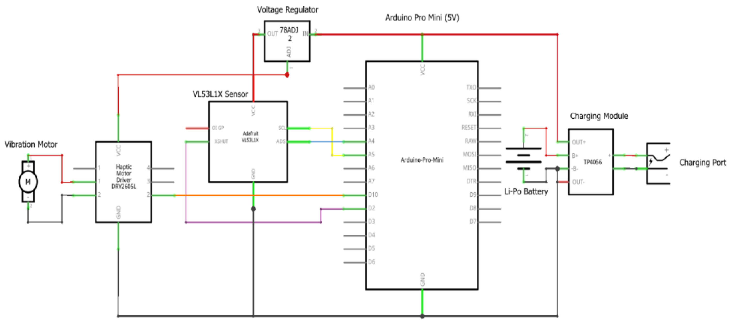
The device includes 3 VL53L1X ToF sensors, an Arduino Pro Mini microcontroller, coin-shaped vibration motor, and power management module. These elements are integrated into a head-mounted configuration designed to provide directional feedback based on real-time obstacle detection (Figure 1).
Each VL53L1X sensor can measure distances up to 400 cm and is positioned at a set angle relative to the consumer’s ahead course. The sensors are arranged to cover a mixed horizontal field of view of approximately eighty-one°, allowing the detection of objects drawing close from the front, front-left, and front-right. This configuration ensures good enough spatial coverage for traditional indoor navigation eventualities.
Every sensor is paired with a corresponding coin-shape vibration motor, which is found at the back of the sensor and aligned with the consumer’s forehead or temple (Figure 1.2). These motors generate tactile remarks in proximity of detected limitations, allowing the user to perceive both the location and relative distance of gadgets within the sensor’s range. The vibration depth is modulated via pulse-width modulation (PWM) signal, to mirror varying levels of proximity, with closer objects producing more potent tactile responses.
The choice of light-weight modules and the use of compact sensors and actuators contribute to the system’s portability and suitability for head-mounted deployment. The association allows for seamless integration into wearable packages whilst preserving steady directional recognition and comfort for the user.
Figure 1.
System circuit diagram.
2.2. Microcontroller and Communication Architecture
The device is controlled via an Arduino Pro Mini microcontroller. It was selected for its compact size, low current draw, and compatibility with I²C communication [9], responsible for sensor initialisation, information acquisition, and vibration control of the device (Figure 2).
The VL53L1X ToF sensors communicate with the Arduino via the I²C protocol. This mechanism enables more than one module to share the same data and clock lines [13]. Since all sensors have the equal default I²C address, specific addressing is applied using dedicated XSHUT (shutdown) pins. During system startup, the microcontroller sequentially activates each sensor and assigns a completely unique address, allowing concurrent operation on the identical I²C bus (Figure 3).
When the Arduino is turned on, it enters a loop condition. It periodically polls each sensor for distance readings. The readings are then compared against a predefined threshold value, initialised at 125 cm, to identify whether an object is inside the actionable detection range.
When an obstacle is detected, the corresponding vibration motor is activated using a pulse-width modulated (PWM) signal. The PWM signal is adjusted proportionally to the measured distance, resulting in elevated vibration strength as the obstacle approaches. These dynamic mechanisms allow the user to obtain both directional and proximity-based information through haptic feedback.
The Arduino Pro Mini is programmed in C++ using Arduino IDE. The code (Figure 2) is optimized for responsiveness and power efficiency for the system to help in real time navigation.
2.3. Power Supply and Regulation
The device runs on a 3.7V lithium-polymer battery. It was selected for its small size, and rechargeability. The Arduino Pro Mini and the VL53L1X sensors need a constant 5V; thus, a boost converter was included. This converter takes the battery’s output and generates a steady 5V. It keeps the device running, even as the battery drains.
A TP4056 charging module is responsible for charging and managing power. It has a USB-C port to recharge the device and safety features built in. This is for protecting against overcharging, low battery, and short circuits, which is essential, especially for head-mounted gear.
The measured consumption of the system is about 495mA when it is running constantly. With a 1000mAh battery, it could expect roughly 2.6 hours of use if operating under full load. Under normal usage, it lasts about 5 hours. This duration is sufficient for short navigational tasks in indoor environments.
2.4. Design and Construction
The structure of the device was designed to prioritise comfort, stability, and functionality for prolonged use. All additives are enclosed in custom-designed, 3D-printed housings using lightweight PLA material. The housings are established onto an adjustable elastic head strap that allows the device to be securely attached onto the user’s head without causing pain or instability throughout movements.
The 3 VL53L1X sensors are fixed on the front of the pinnacle strap, each angled outward together to gain a complete subject of view of approximately 81°. Directly behind each sensor, a corresponding coin-type vibration motor is embedded into the housing to ensure that tactile feedback is brought exactly to the forehead and temples, improving spatial awareness.
The rear segment of the strap houses the Arduino Pro Mini, the lithium-polymer battery, power regulation circuitry, and the TP4056 charging module. This rear-mounted arrangement was chosen to provide stability of the general weight of the tool and minimise ahead pull, which could in any other case lead to strain on the consumer’s head or neck.
Wiring between the modules is routed along the internal side of the strap and secured using included cable channels to save entanglement or interference with outside gadgets. The total device weight remains inside a wearable threshold. The modular shape also enables future factor replacement or upgrades without significant redesign.
3. Results and Discussion
3.1. Sensor Accuracy and Measurement Validation
To validate the accuracy of the VL53L1X Time-of-Flight sensors used in the prototype, a sequence of static distance measurements was performed under managed indoor conditions (Figure 4). A breadboard assembly with one sensor became used, and a flat white wall served as the target floor. Measurements have been taken at ten fixed distances, ranging from 150 cm to 15 cm, in 15 cm durations. Each measurement was repeated three times per distance to evaluate repeatability (Figure 4).
The results were compared with the manufacturer’s reference facts and were regular (Figure 5). The calculated values and preferred deviations indicate that the readings were inside a suitable ±1 cm margin of error, with minor deviations attributed to manual measurement inaccuracies.
3.2. Comparison with Manufacturer Specifications
Figure 4 (above) and Figure 5 (below) display a fixed outcome that can be aligned within the overall performance curves, indicating the sensor’s performance was in line with the manufacturer’s data sheet [7]. A minor deviation was found at the 100cm mark, which stems from moderate inaccuracies in distance placement. Importantly, this does not affect the device’s basic functionality, as the haptic comments set of rules utilise discrete distance zones as opposed to absolute precision.
3.3. Feedback Performance and Interpretation
The feedback system was examined concurrently with the sensing module. Vibration motors activated whilst objects were detected inside the 125 cm threshold, with intensity modulated [8] using pulse-width modulation (PWM) based on proximity. Each motor was successfully mapped to its corresponding sensor, allowing users to interpret both direction and distance primarily based on the area and strength of the vibration.
3.4. Observations and Limitations
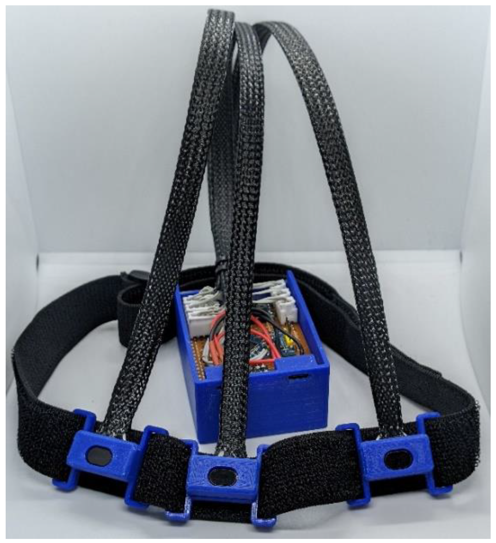
The device (Figure 6) performed reliably in indoor conditions, demonstrating correct sensing and regular haptic signaling. However, modern-day design lacks downward-facing sensors, which limits the potential to detect upon low-laying risks that include curbs or steps. Additionally, the gadget is yet to be evaluated under outside lighting conditions, where ambient, mild or reflective surfaces may additionally influence the sensor’s overall performance. These elements highlight areas for capability development in future iterations of the layout.
4. Conclusions
This work offered the design, development, and evaluation of a head-mounted assistive device to improve spatial consciousness for people with visual impairments [1]. The device integrates a compact array of VL53L1X ToF sensors with directional haptic feedback introduced through coin-like vibration motors. A low-electricity Arduino Pro Mini microcontroller manages sensors and generates pulse-width modulated output indicators based on obstacle proximity.
Testing validated reliable obstacle detection within 15 cm to 150 cm, with dimension deviations within ±1 cm. The haptic feedback system was responsive, directionally accurate, and proportional to item distance. A statistical power analysis confirmed the gadget’s efficiency, with a runtime of 2.6 to 5 hours depending on usage conditions.
The latest version of the prototype is compact, lightweight, and value-add, making it suitable for indoor navigation tasks. Whilst the device performed well in static indoor settings, future works will address its limitations by incorporating additional sensors for ground-stage boundaries and conducting evaluations under dynamic and outdoor conditions. Overall, findings suggest that the proposed gadget offers a sensible answer for boosting mobility and independence amongst visually-impaired users.
Author Contributions
Mr Malek Al Maraashli designed and constructed the prototype device over a period of two years supervised by Dr Mansour Youseffi at University of Bradford. Dr Luca Parisi and Dr Renfei Ma assisted with the technical aspects/improvements and reviewing this article.
Conflicts of Interest
The authors declare no conflicts of interest.
References
- Sense, “Blindness and visual impairment,” sense.org.uk. [Online]. Available: https://www.sense.org.uk/what-we-do/research-policy/briefings/blindness-and-visual-impairment/.
- Vision Foundation, “White Canes: Myth-Busting and Learning,” visionfoundation.org.uk, 2022. [Online]. Available: https://www.visionfoundation.org.uk/white-canes-myth-busting-and-learning/.
- BAWA Cane, “How to Pick the Correct Length of a White Cane,” bawa.tech, 2023. [Online]. Available: https://bawa.tech/blogs/news/how-to-pick-the-correct-length-of-a-white-cane.
- WatElectronics, “Ultrasonic Sensor – Working, Specification, and Applications,” watelectronics.com, 2022. [Online]. Available: https://www.watelectronics.com/ultrasonic-sensor-working-specifications/.
- VisionAid Technologies Ltd., “OrCam MyReader 2,” visionaid.co.uk, 2024. [Online]. Available: https://www.visionaid.co.uk/orcam-myreader-2.
- ElectricalFundablog, “IR Sensor – Working, Types, and Applications,” electricalfundablog.com, 2023. [Online]. Available: https://www.electricalfundablog.com/ir-sensor-working-types-applications/.
- STMicroelectronics, “VL53L1X – Long Distance Ranging Time-of-Flight Sensor,” st.com. [Online]. Available: https://www.st.com/en/imaging-and-photonics-solutions/vl53l1x.html.
- Vybronics, “VC1234B016F Coin Vibration Motor,” vybronics.com. [Online]. Available: https://www.vybronics.com/products/vc1234b016f.
- SparkFun Electronics, “I²C Protocol Tutorial,” learn.sparkfun.com. [Online]. Available: https://learn.sparkfun.com/tutorials/i2c.
- Macular Society, “Low Vision Aids,” macularsociety.org. [Online]. Available: https://www.macularsociety.org/about-macular-disease/living-with-sight-loss/low-vision-aids/.
- Vision Australia, “White Canes: What You Need to Know,” visionaustralia.org. [Online]. Available: https://www.visionaustralia.org/information/blindness/white-canes.
- World Health Organization (WHO), “Blindness and vision impairment,” who.int, Oct. 2023. [Online]. Available: https://www.who.int/news-room/fact-sheets/detail/blindness-and-visual-impairment.
- SFUPTOWNMAKER, “SparkFun I²C Tutorial (Video),” YouTube, Nov. 2022. [Online]. Available: https://www.youtube.com/watch?v=5KivEmq5dO8.
- Lanzillotta, M., Ma, R., Accardi, M., RaviChandran, N., Zaernia, A., Youseffi, M., & Parisi, L. (2022). Neuroevolutionary intelligent system to aid diagnosis of motor impairments in children. Applied Intelligence, 52(9), 10757-10767. [CrossRef]
- Parisi, L., & RaviChandran, N. (2020). Evolutionary denoising-based machine learning for detecting knee disorders. Neural Processing Letters, 52(3), 2565-2581. [CrossRef]
- Parisi, L., & RaviChandran, N. (2018, April). Genetic algorithms and unsupervised machine learning for predicting robotic manipulation failures for force-sensitive tasks. In 2018 4th International conference on control, automation and robotics (ICCAR) (pp. 22-25). IEEE. [CrossRef]
Figure 2.
Code flow chart.
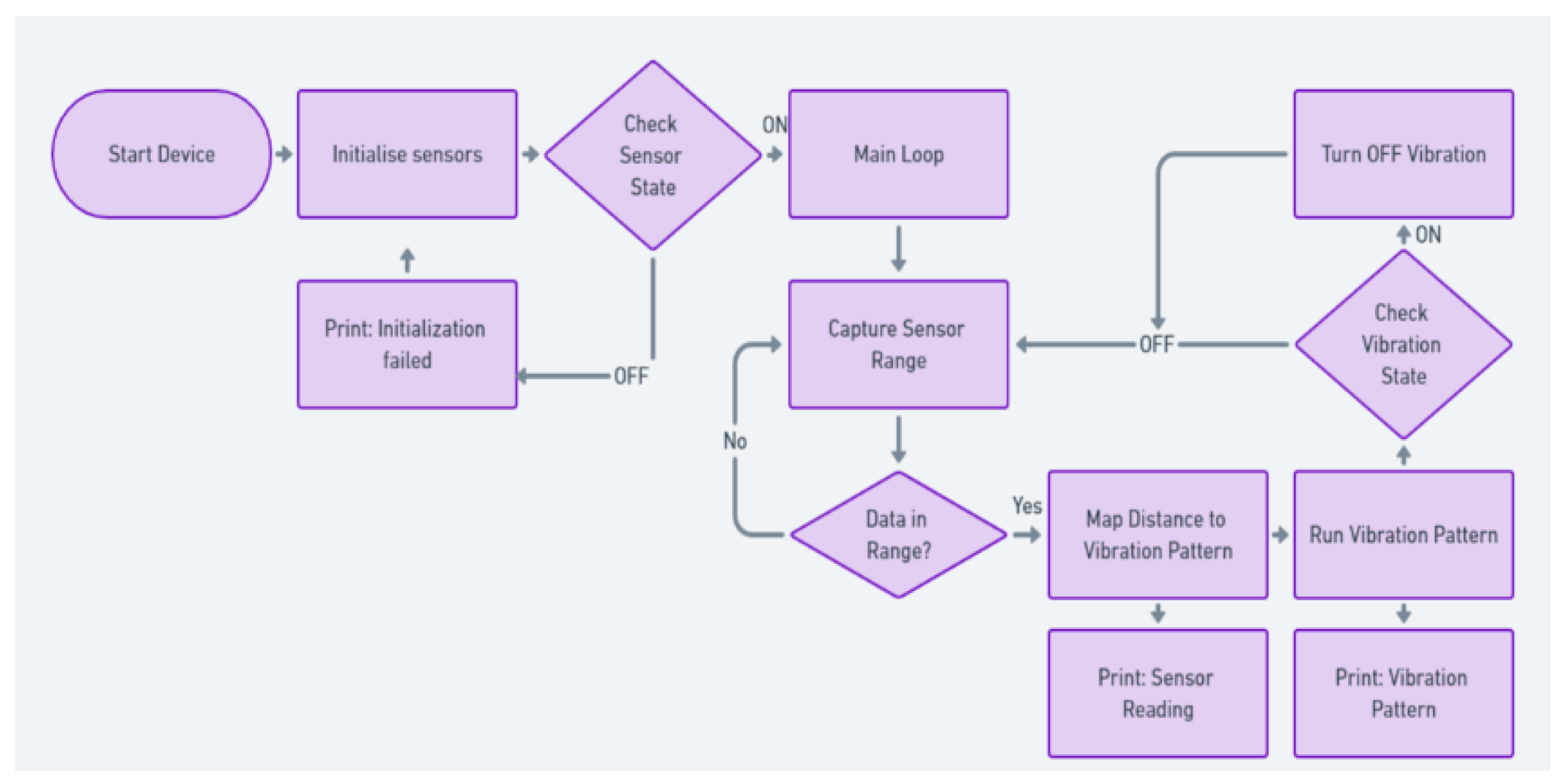
Figure 3.
Sensors layout.
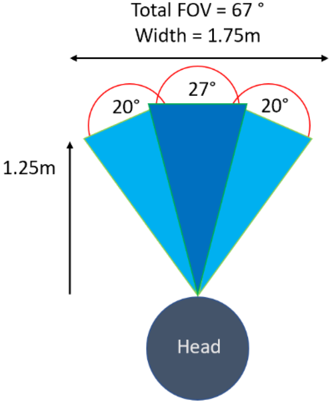
Figure 4.
Measurement results.
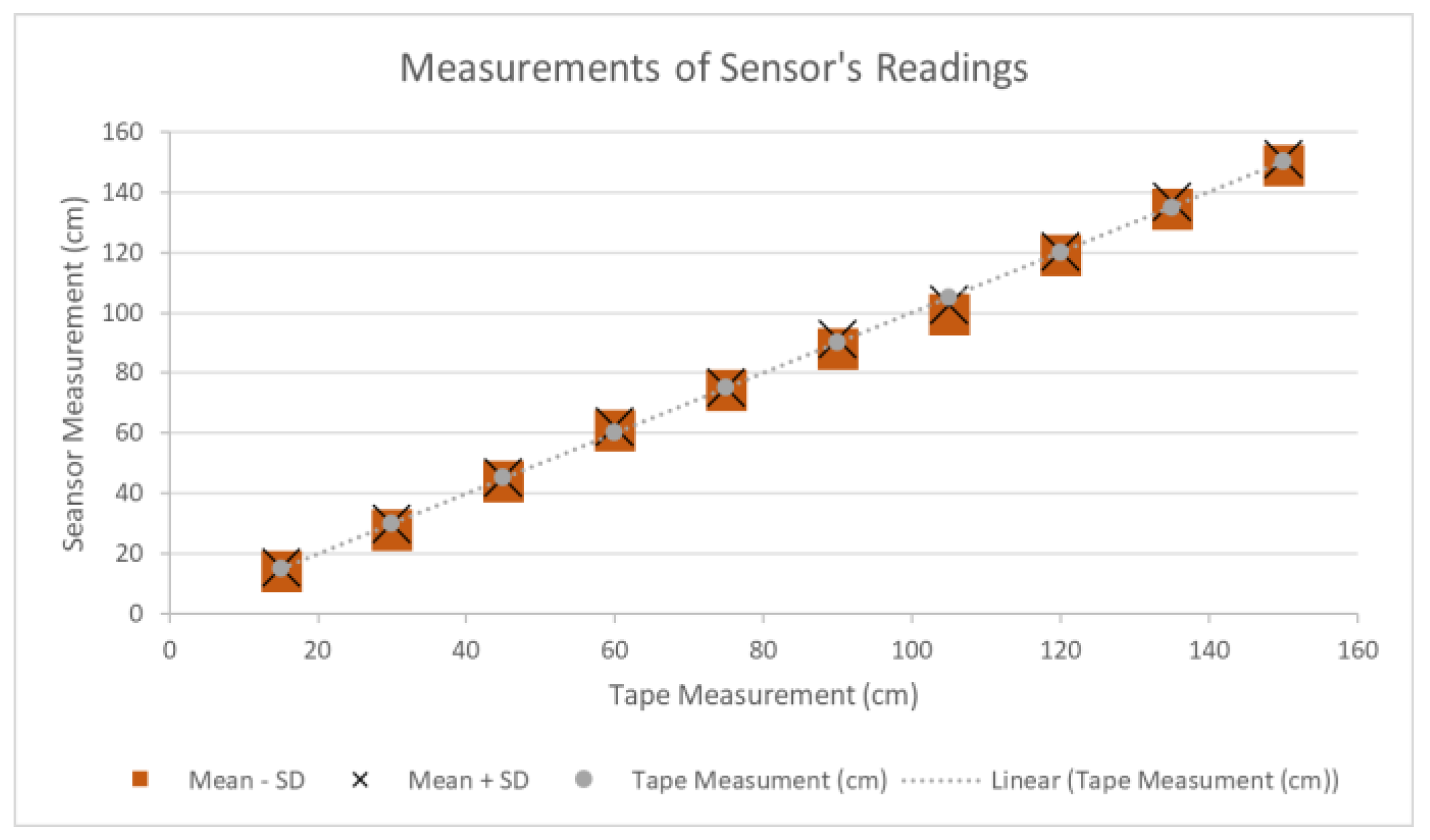
Figure 5.
Manufacturer’s results.
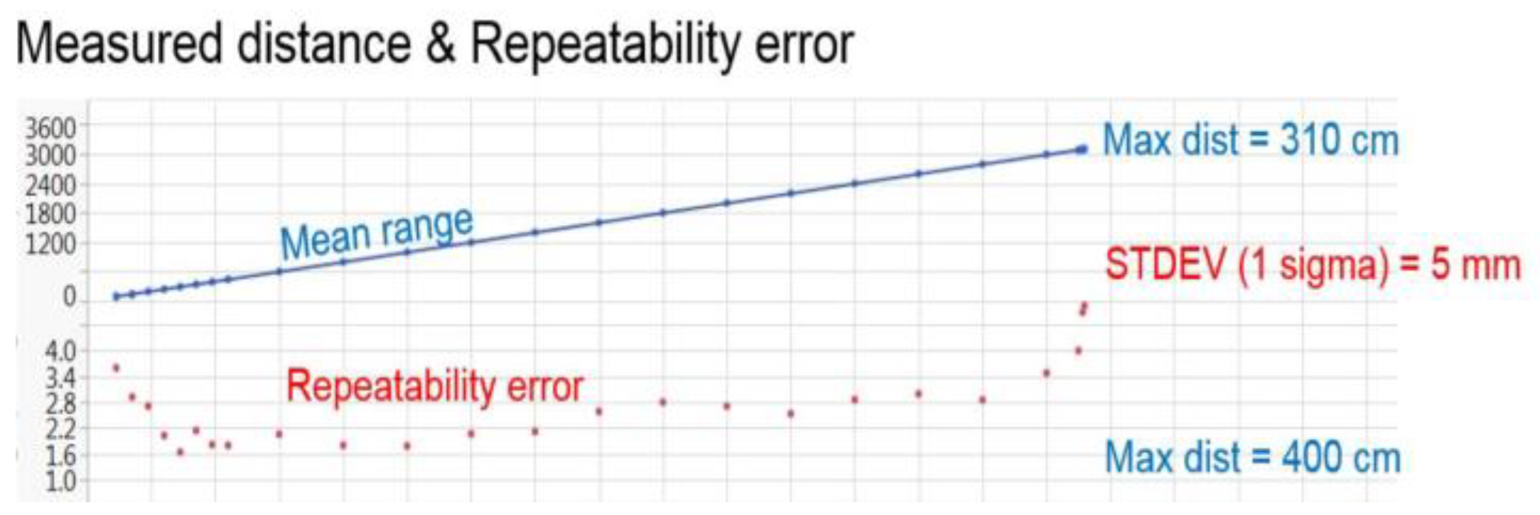
Figure 6.
Devica prototype.
Disclaimer/Publisher’s Note: The statements, opinions and data contained in all publications are solely those of the individual author(s) and contributor(s) and not of MDPI and/or the editor(s). MDPI and/or the editor(s) disclaim responsibility for any injury to people or property resulting from any ideas, methods, instructions or products referred to in the content. |
© 2025 by the authors. Licensee MDPI, Basel, Switzerland. This article is an open access article distributed under the terms and conditions of the Creative Commons Attribution (CC BY) license (http://creativecommons.org/licenses/by/4.0/).
Copyright: This open access article is published under a Creative Commons CC BY 4.0 license, which permit the free download, distribution, and reuse, provided that the author and preprint are cited in any reuse.


