
Submitted:
04 April 2025
Posted:
07 April 2025
You are already at the latest version
Abstract
This work presents a study on the calculation of transmittance in an Air Handling Unit (AHU) through three methods: theoretical estimation, experimental approach and numerical simulations. First, a theoretical estimation based on simplified models of heat and mass transfer in the AHU was employed. In addition, experimental tests were carried out in a real AHU under controlled conditions, obtaining temperature measurements inside and outside the unit. These data were used to calculate the transmittance using predefined formulas. Finally, numerical simulations were performed on specific sections of the AHU and on a global model, with and without radiation considering its influence. The simulations provided detailed results on the flow behaviour and temperature distribution. The results obtained were compared and analysed to assess the accuracy and applicability of the three methods. This research contributes to the knowledge and understanding of transmittance in AHUs, providing valuable information for the design and optimisation of Heating, Ventilation, and Air Conditioning (HVAC) systems.
Keywords:
Emissivity
; Thermal Bridging
; OpenFOAM
; AHU
; HVAC
; Trasmittance
1. Introduction
An air handling unit (AHU) is a machine that conditions rooms and chambers using heat exchangers [1]. They are responsible for circulating air in houses or buildings. AHUs are components of heating, ventilation, and air conditioning (HVAC) systems. They are large metallic boxes comprising a blower, filter racks, sound attenuators, and cooling and heating coils. They are installed inside and outside buildings, with the rooftop being typical for the latter where control is a challenging task [2,3]. Often, they are connected to the HVAC’s ductwork [4]. The main components of an AHU system are its casing or housing, the fan, the heating and cooling coil, filters, humidifiers, and the mixing box. The primary function is heat exchange [5] and filtering, improving the air quality. To improve their efficiency, the design of air handling units requires studies of thermal losses due to conduction and convection [6,7]. Efficiency is only sometimes an easy parameter to obtain [8]. Many factors that complicate designs are thermal bridges [9] or parameters that are difficult to measure, such as radiation heat transfer coefficients. In this case, the type of radiation can be a limiting factor, as the surfaces do not behave the same depending on the incident wavelength. Thermal bridges are essential for the overall efficiency of the units [10]. However, their constitution is complex [11], and they can be a determining factor in the outcome of unity. The bridging effects are remarkable compared to low-transmission panels, thanks to vacuum-insulated panels. This is marked by regulations that need to be permanently improved due to the implications of improvements to comply with environmental regulations, such as, for instance, EU regulation 1253/2014 [12]. The study involves the three known methods of heat exchange: conduction, convection and radiation [13]. Fluid dynamic phenomena that define their efficiency has to be also considered. This is especially relevant in the case of filtration efficiencies. The test conditions require applying relevant techniques in measuring temperatures decoupled from radiative interference and temperatures on surfaces, where the effects of radiation must be considered [14]. This paper presents a simplified methodology to estimate the energy efficiency of an AHU design. The primary objective is to present a semi-empirical procedure for the estimation of energy consumption and evaluate the class of the pre-designed unit according to the European Standard EN 1886:2008 [15]. The results obtained with this methodology are validated both with numerical computations in a 2D model and with experimental measurements on a AHU box unit. The paper is organized as follows. In section two, a semi-empirical estimation is presented. Section 3 describes an experimental set-up, emphasising mitigating the error that could be neglected. Numerical studies are a relevant part to be compared on the semi-empirical proposal and are validated using the experimental results. The numerical results are presented in Section 3. Finally, Section 4 presents an extensive discussion of comparing the results.
2. Semi-Empirical Estimation
Thermal transmittance (U) is defined as the ability of the unit to transmit heat under steady-state conditions. It is estimated as the ratio between heat transfer per area unit and the difference of temperature
where is the total heat transfer, per unit area, and and are the inside and outside temperatures of the AHU, as depicted in Figure 1. It can also be described as the sum of the reciprocals of the resistances of the elements of the unit, and is expressed in
The heat transmitted, per surface unit, by conduction is given by Fourier’s law of heat conduction,
where is the isolation thermal conductivity, e is the wall thickness and and are, respectively, the outer and inner wall temperature (see Figure 1) Convection heat transfer is determined with
where h is the convection heat transfer coefficient, which does not depend exclusively on the fluid, but it is also influenced by the geometry of the surface, the nature of the fluid movement and its average speed. Convection heat transfer coefficient is computed with the Nusselt number
where is the thermal conductivity of the medium and d is a characteristic length. In the following, the expressions used to estimate Nu and hence h, have been based on the book by Çengel and Ghajar [6], and references therein. Convective heat transfer is estimated both inside and outside the AHU and the term in equation (3) refers to the temperature difference between the wall and the far field. Outside the unit only natural convection holds, and Nusselt number is estimated with the expression
where c and n are function of the wall orientation and the value of the outer Rayleight number, . Table 1 shows the values used in the present estimation.
Rayleigh number is computed as the product of Grashof number and Prandtl number,
where
and
where is the viscosity of air, is the specific heat at constant pressure, is the thermal expansion coefficient of air, L is the height of the unit, g is the gravity acceleration, is the far temperature, and is the outside wall temperature. Hence, outer heat transfer coefficient is computed as
Note that, actually, there are three different values of depending on the orientation of the surface relative to gravity (lateral walls, top wall and bottom wall).
Inside the AHU, besides natural convection, forced convention has to be considered, due to the air circulation required by the Standard [15] in order to keep an uniform distribution of inner temperature. The Nusselt number for the forced convection is estimated with
where , is the average velocity of air inside the unit and is the hydraulic diameter. The natural convection inside the AHU is computed with the correlation found by Globe and Dropkin [16] for a rectangular box heated from below
When both natural and forced convention are combined, the effective Nusselt number is usually estimated with [6]
and
The heat transfer by radiation is estimated with
where W/m2K4 is the Stefan-Boltzmann constant and is the effective emissivity due to the 4 surfaces that compose the isolation bounding walls. It is assumed that the insulator and air are transparent in the bandwidth of thermal radiation. The emissivity of the surfaces is measured with a thermographic camera.
Finally, the heat transfer in the metallic profiles of the AHU is estimated, considering only the conduction due to the metal and neglecting the effect of the air chambers.
The convective and conductive heat transfer are combined as
where . The total heat transfer is the sum of this and the radiation term
However, this total heat transfer is function of the wall temperatures, and , which are, at first, unknown. This temperatures are computed with
where
where and are, respectively, the emissivity of the inner and outer surface of the AHU.
Equations (16), (17) and (18) are iteratively solved until a solution for , and is reached, and thermal transmitance is computed with (1). The flowchart for this procedure is depicted in Figure 2.
Thermal bridge factor is defined in the Standard [15] as the rate between the minimum difference of temperatures inside and in the outside wall, and the temperature difference inside and outside the AHU,
In the present estimation, since wall temperatures are considered uniform, it is computed as
3. Numerical Methodology
Numerical experiments have been performed with the toolbox OpenFOAM version 9 [17], that uses Finite Volume Method to solve systems of partial differential equations. The solver used has been chtMultiRegionFoam which is used for steady or transient fluid flow and solid heat conduction. Furthermore, it conjugates heat transfer between regions, buoyancy effects, turbulence, reactions, and radiation modeling. The simulations are steady, and they have been run until convergence of heat flux is reached.
The mesh is two-dimensional for the sake of simplicity and simulation speed. The mesh is composed of several regions that cover both fluid and solid domains. Fluid regions include the interior and exterior air spaces of the AHU, while solids consist of metallic sheets and insulation materials that form the walls of the AHU. In addition, a solid heater with constant temperature is modeled in the lower part of the inner space. Using the symmetry of the system, only half of the domain was simulated.
The mesh was generated using the blockMesh tool included in the OpenFOAM distribution, which constructs structured hexahedral blocks. To streamline the creation of complex block configurations, the Python tool ofblockmeshdicthelper [18] was used.
The regions considered in the simulations are the inner air, the outer air, the insulator, the metal sheets, both inner and outer, and, finally, the heater. These regions are schematically shown in Figure 3, except metal sheets enclosing the insulation.
For the fluid regions, chtMultiRegionFoam solves continuity equation
the momentum equation
with , and the energy equation
where is the density, the velocity, is the pressure corrected with gravity effect, is the stress tensor, is the kinetic energy, h is the enthalpy, R is the radiation term and and are, respectively, effective viscosity and heat transfer coefficient, corrected by turbulence modelling. In the present case, standard has been used as a turbulence model, as it has proven to be a suitable model, combining acceptable accuracy and computational resource consumption for buoyancy-driven flows [19].
For the solid regions, only heat conduction is solved,
In the interfaces between solids and fluids the solver imposes the same temperature
and, also, continuity of heat transfer is ensured
For the computation of convection, air is treated as compressible with the Boussinesq approximation and the density is uniquely function of the temperature,
where kg/m3, K and K−1 is the thermal expansion coefficient.
The radiation term R in equation (25) is computed by the solver using the view factor method [6,13], where the radiative heat transfer is estimated by generating discrete rays between solid surfaces. For the sake of comparison, this term has been disabled on some numerical experiments.
Regarding to boundary conditions for momentum, the external part of the domain shown in Figure 3 has been defined as wall with no slip condition for velocity ans constant temperature. The left side of the domain has been set as a symmetry plane when radiation was disabled. However, since the view factor method does not support symmetry constraints, these boundaries have been defined as slip condition for velocity and zero gradient for other variables when radiation was enabled. The temperature of the heater solid has been established at a constant value.
Transmittance is numerically computed with
where the sum of heat transfers includes the heat transfer from the conduction/convection and the heat transfer from the radiation. The thermal bridge factor is estimated using the equation Eq. 32.
4. Experimental Methodology
The scheme of the experimental rig is presented in Figure 4. Generation and control of the internal temperature of the AHU, 4 axial fans, 2 heaters and a temperature controller were installed. A Circutor CVM-C10 analyser was used to measure the power consumed. The fans have a capacity of each and circulate the air at about 100 AHU volumes per hour. They were installed in the middle longitudinally of the AHU to circulate the air crosswise. The heaters are electric resistance type and each have a capacity of 400 W. They are regulated by an ON/OFF temperature controller. It is equipped with an NTC temperature sensor which is located inside the unit.
For temperature acquisition, a total of 20 copper T-type thermocouples with 0.2 mm wire were installed. 16 were installed inside the box as shown in Figure 5 from 1 to 16, ant the other 4 were installed outside marked from 17 to 20. The internal thermocouples were installed 100 mm from the panels by using 4 wires crossing the longest part of the enclosure. The external thermocouples were installed centred 250 mm from the face of the corresponding wall, the top, the back and the two side walls. The 20 thermocouples were connected to a data acquisition unit, DAQ970A by Keysight, equipped with a 20 channels multiplexor.
The transmittance is experimentally estimated with
where the electric power consumed is given by the analyser and the outer surface of the box is A = m2.
The thermal bridge is estimated with
where
5. Results Comparison and Discussion
After running the simulations for the calculation of the Grid Convergence Index, the asymptotic ratio was 0,9973. As this value is close to 1, it can be concluded that the mesh is valid. The values from this study are presented in Table 2.
A significant difference is observed between the numerical and theoretical results of the thermal transmittance without radiation, as shown in Table 3, with a numerical value a 67% higher than the theoretical one. This indicates that, in the absence of radiation, the numerical calculation produces a higher estimate of thermal transmittance compared to the theoretical approach. On the other hand, when considering the thermal bridge, the theoretical solution shows a slight superiority of about 2% compared to the numerical result. In this case radiation has not been activated, and thermal transmittance is largely underestimated.
A comparison between the results obtained in the experimental part and those obtained in the numerical simulation and theoretical estimation in the absence of radiation could not be undertaken, due to the impossibility to completely eliminate radiation in the experiments.
The results comparison among the three different methods with the global model with heat flux can be looked up in Table 4.
When comparing the numerical results in the presence of radiation, significant differences are observed in relation to the experimental and theoretical results. In the case of thermal transmittance, the lowest estimate corresponds to the experimental results, while the numerical results are 8% higher. On the other hand, the theoretical estimation is even further away from the experimental results, being 38% higher in comparison. Likewise, the theoretical estimate is 28% higher in relation to the numerical results. Regarding the thermal bridge factor, the highest estimation is the one obtained through the experiments, exceeding the numerical results by 3% and the theoretical results by 8%.
Through numerical simulations, it has been possible to determine that the result of the heat transmitted was W/m2 and a value of the transmittance of W/m2K.
Figure 7 shows the distribution of velocity.
Figure 7.
Velocity fields of CFD simulations with and without radiation. Units are in m/s.
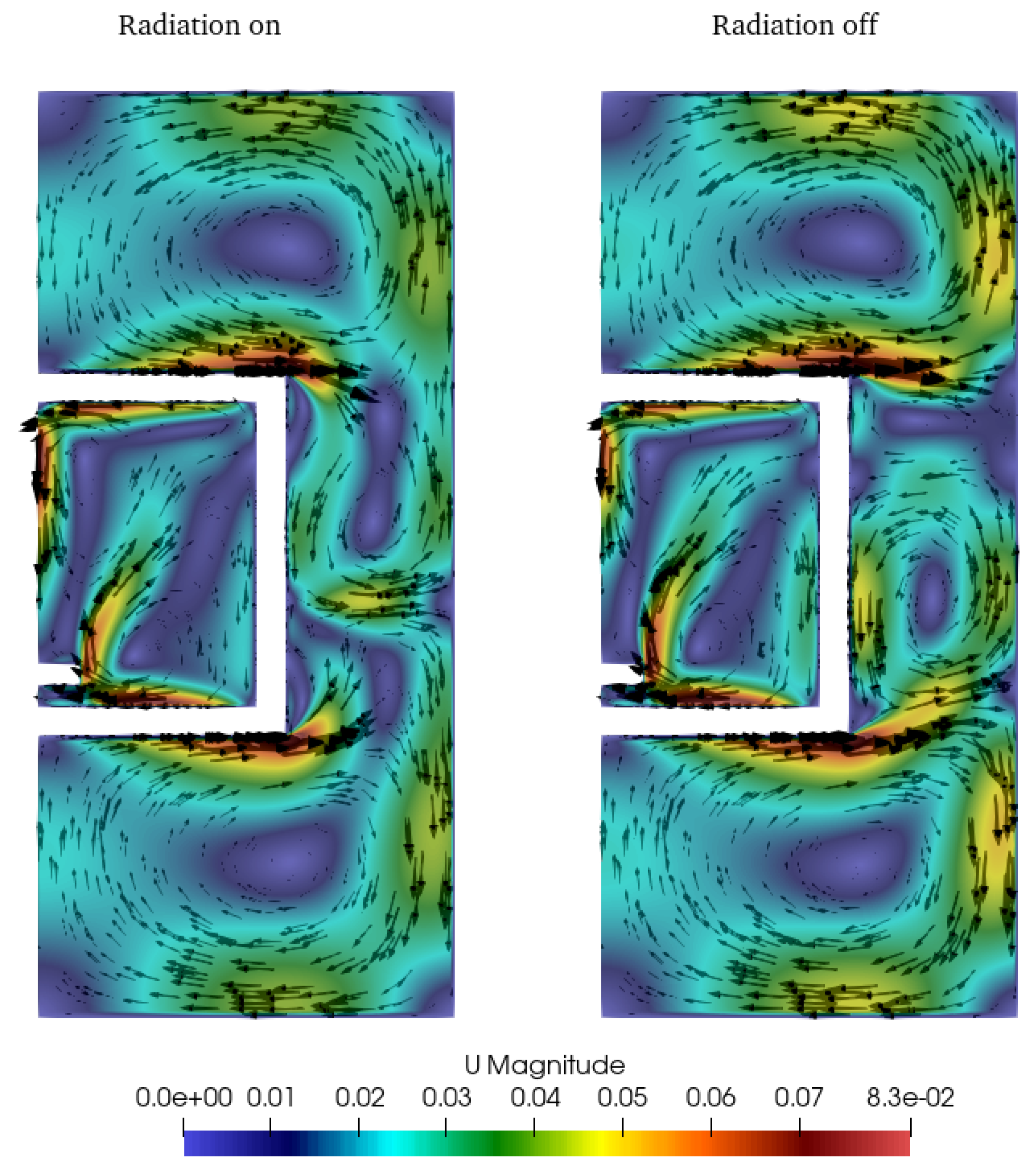
Figure 8.
Temperature distribution of CFD simulations with and without radiation. Units are in K.
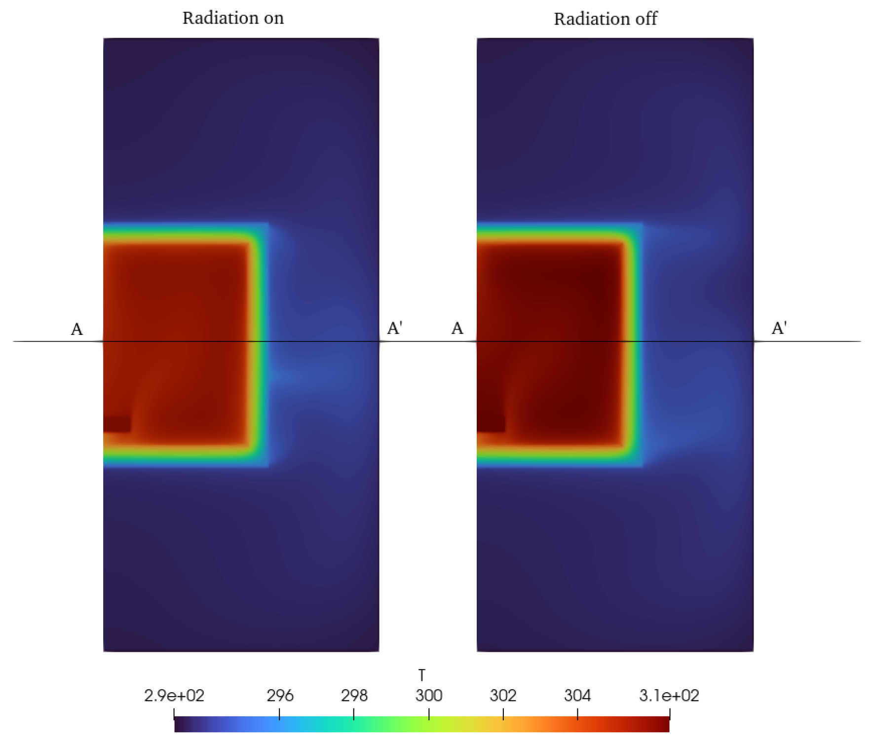
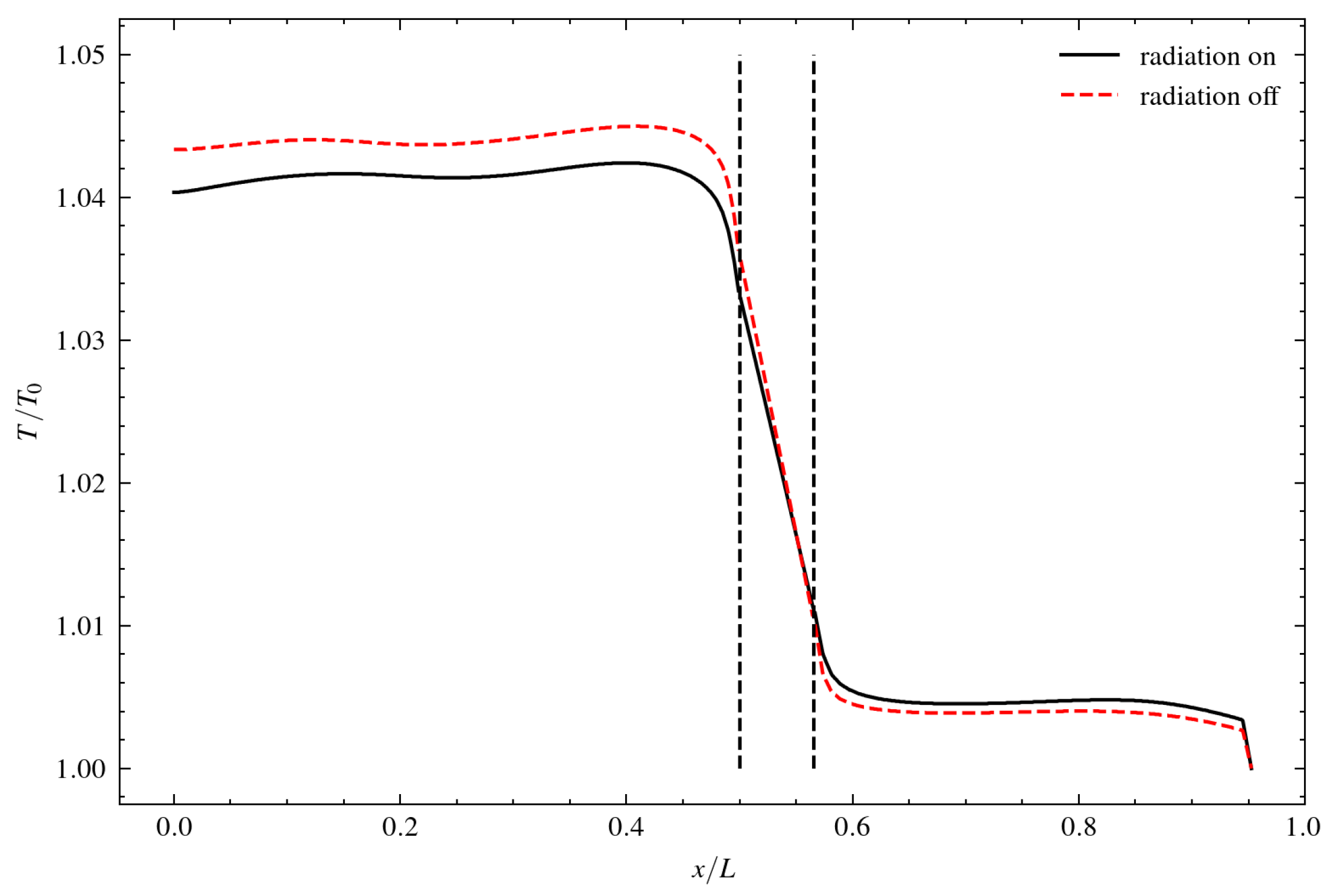
Figure 9.
Temperature distribution along lines A-A’ of Figure 8. Vertical black dashed lines are limits of the wall with insulation.
Figure 9.
Temperature distribution along lines A-A’ of Figure 8. Vertical black dashed lines are limits of the wall with insulation.
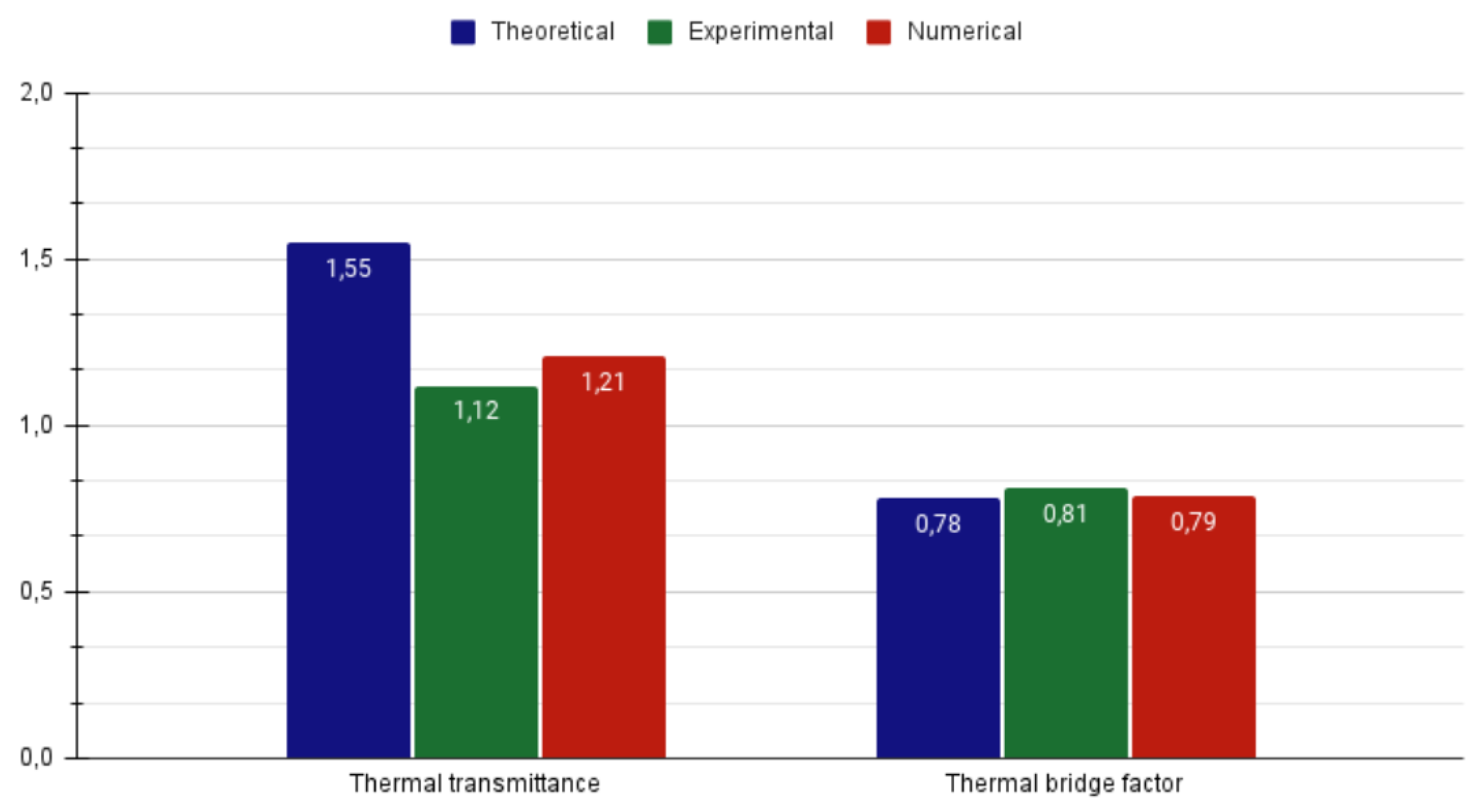
Results when radiation is activated in the global model are shown in the bar plot of Figure 10. Numerical computation agrees very well with experimental measurement with a value that is only 8% larger. Theoretical estimate, however, overestimates the value of U in more than 38%.
6. Conclusions
It has been demonstrated the importance of using multiple methods, such as theoretical estimation, experiments and numerical simulations to obtain accurate and clarifying results in the study on the calculation of transmittance in air handling units. The combination of these three methods has led to more reliable results and a more complete understanding of transmittance in AHUs. This information is crucial for the efficient design and effective operation of hair conditioning and ventilation systems (HVAC), as AHUs are key elements of HVAC, which in turn contributes to the improvement of energy efficiency and indoor air quality.
In general, it is observed that the theoretical results and the numerical simulations for the different sections of material 1 are quite similar where in most cases the numerical estimation is higher by up to 22%, depending on the case. This indicates a reasonable concordance between the two methods and suggests a fair accuracy in the theoretical estimation. On the other hand, the results for materials 2 and 3 are remarkably accurate as the difference between the results is 1% and 11% respectively, indicating a high reliability in the numerical simulations.
Convection plays a crucial role in heat transfer, being more relevant than conduction in many of the cases studied. The influence of the convection flow velocity and the characteristics of the fluids in contact with the surfaces are decisive in heat transfer. In addition, radiation is a key point in the simulations, as it is the closest to the results obtained experimentally and, therefore, the closest to reality.
Geometry and boundary conditions have a significant impact on the heat transfer results. Different shapes, such as straight profiles or corners, have been observed to lead to different heat transfer patterns.
The presence of external forces, such as gravity, can modify the heat transfer significantly. In the case of the bottom panel, a remarkable decrease in heat transfer has been observed due to the influence of gravity in the negative direction.
This research provides a solid basis for further progress in the calculation of transmittance in AHUs and contributes to the knowledge in the field of air conditioning and ventilation, with the aim of achieving a healthy, comfortable and sustainable indoor environment.
Moreover, future work should focus on the refinement and improvement of the theoretical models and numerical simulations, taking into account additional factors such as the interaction between components, the variability of environmental conditions and the inclusion of other relevant parameters. Furthermore, it is suggested that future research should focus on overcoming experimental limitations to obtain more reliable and comparable results, which will contribute to a more complete understanding of transmittance in AHUs and to the improvement of air-conditioning and ventilation systems.
Author Contributions
M. Garcia-Vilchez: Conceptualization, Writing – original draft, Writing – review & editing , Formal analysis. P. Torres: Writing – original draft, Writing – review & editing, Methodology, Investigation, Software, Visualization. G. Raush: Formal analysis, Investigation, Methodology, Validation, Writing – original draft. M. Torrent: Formal analysis, Methodology, Writing – review & editing. R. Castilla: Conceptualization, Funding acquisition, Methodology, Software, Supervision, Writing – original draft, Writing – review & editing , M. Morte: Project administration.
Conflicts of Interest
The authors declare no conflicts of interest.
Abbreviations
The following abbreviations and symbols are used in this manuscript:
| AHU | Air handling unit |
| HVAC | Heating, ventilation, and air conditioning |
| Specific heat at constant pressure | |
| d | Characteristic length |
| Hydraulic diameter | |
| e | Wall thickness |
| g | Gravity acceleration |
| Outlet Grashof number | |
| h | Convection heat transfer coefficient |
| Convection and conduction heat transfer coefficient | |
| Thermal bridge factor | |
| L | Height of the unit |
| Nusselt number | |
| Inside Nusselt number | |
| Outside Nusselt number | |
| Pr | Prandtl number |
| Outer Rayleigh number | |
| Conduction heat transfer per unit area | |
| Convection heat transfer per unit area | |
| Convective and conductive heat transfer per unit area | |
| Radiation heat transfer per unit area | |
| Total heat transfer per unit area | |
| Inside temperature | |
| Outside temperature | |
| Inner wall temperature | |
| Outer wall temperature | |
| Average velocity of air inside the unit | |
| U | Thermal transmittance |
| Thermal conductivity of the medium | |
| Isolation thermal conductivity | |
| Thermal expansion coefficient of air | |
| Effective emissivity | |
| Emissivity of the inner surface | |
| Emissivity of the outer surface | |
| Viscosity of air | |
| Density of air | |
| Stefan-Boltzmann constant |
References
- Lun, Y.H.V.; Tung, S.L.D., Air Handling Unit. In Heat Pumps for Sustainable Heating and Cooling; Springer International Publishing: Cham, 2020; pp. 51–64. [CrossRef]
- Ghawash, F.; Hovd, M.; Schofield, B.; Monteiro, D. Model Predictive Control of Air Handling Unit for a Single Zone Setup. In Proceedings of the 2022 IEEE International Symposium on Advanced Control of Industrial Processes (AdCONIP). IEEE, aug 2022, pp. 158–163. [CrossRef]
- Goldanlou, A.S.; Kalbasi, R.; Afrand, M. Energy usage reduction in an air handling unit by incorporating two heat recovery units. Journal of Building Engineering 2020, 32, 101545. [Google Scholar] [CrossRef]
- Kt, B.; Babu, G.H.S.; Reddy, G.S.; Teja, E.; Krishna, B.S. Design of an Air Conditioning System for a Commercial Building using Air Handling Unit. International Journal of Trend in Scientific Research and Development (ijtsrd), ISSN: 2456-6470, 2019, 4, 192–195. [Google Scholar]
- Shah, R.; Sekulić, D. Fundamentals of heat exchanger design; Wiley, 2003.
- Çengel, Y.; Ghajar, A. Heat and Mass Transfer: Fundamentals and Applications, 6th ed.; McGraw-Hill, 2020.
- Bergman, T.L.; Lavine, A.S.; Incropera, F.P.; DeWitt, D.P. Introduction to heat transfer; John Wiley & Sons, 2011.
- Martinaitis, V.; Streckiene, G.; Bagdanavicius, A.; Bielskus, J. A comparative thermodynamic analysis of air handling units at variable reference temperature. Applied Thermal Engineering 2018, 143, 385–395. [Google Scholar] [CrossRef]
- Desjarlais, A.O.; McGowan, A.G. Comparison of experimental and analytical methods to evaluate thermal bridges in wall systems, 1997. [CrossRef]
- Nagy, B.; Marosvölgyi, M.; Szalay, Z. Comparison of thermal bridge calculation methods. Acta Polytechnica CTU Proceedings 2022, 38, 77–83. [Google Scholar] [CrossRef]
- Liang, W.; Di, X.; Zheng, S.; Wu, L.; Zhang, J. A study on thermal bridge effect of vacuum insulation panels (VIPs). Journal of Building Engineering 2023, 71, 106492. [Google Scholar] [CrossRef]
- Comission, E. Comission Regulation (EU) No 1253/2014 - implementing Directive 2009/125/EC of the European Parliament and of the Council with regard to ecodesign requirements for ventilation units, 2014.
- Incropera, F.P.; DeWitt, D.P. Introduction to heat transfer, 3. ed ed.; Wiley: New York, NY [u.a.], 1996. Literaturangaben.
- Sparrow, E. Radiation Heat Transfer between Surfaces; Vol. 2, Advances in Heat Transfer, Elsevier, 1965; pp. 399–452. [CrossRef]
- CEN. EN 1886:2008. Ventilation for buildings. Air handling units. Mechanical performance. Standard, BSI Standards Limited, 2008.
- Globe, S.; Dropkin, D. Natural-convection heat transfer in liquids confined by two horizontal plates and heated from below. Journal of Heat Transfer 1959, 81, 24–28. [Google Scholar] [CrossRef]
- Greenshields, C.; Weller, H. Notes on Computational Fluid Dynamics: General Principles; CFD Direct Ltd: Reading, UK, 2022. [Google Scholar]
- Aoki, T. ofblockmeshdicthelper. https://github.com/takaakiaoki/ofblockmeshdicthelper, 2023.
- Ahmadi, V.E.; Erden, H.S. A parametric CFD study of computer room air handling bypass in air-cooled data centers. Applied Thermal Engineering 2020, 166, 114685. [Google Scholar] [CrossRef]
Figure 1.
Scheme of the AHU with inside and outside temperatures.
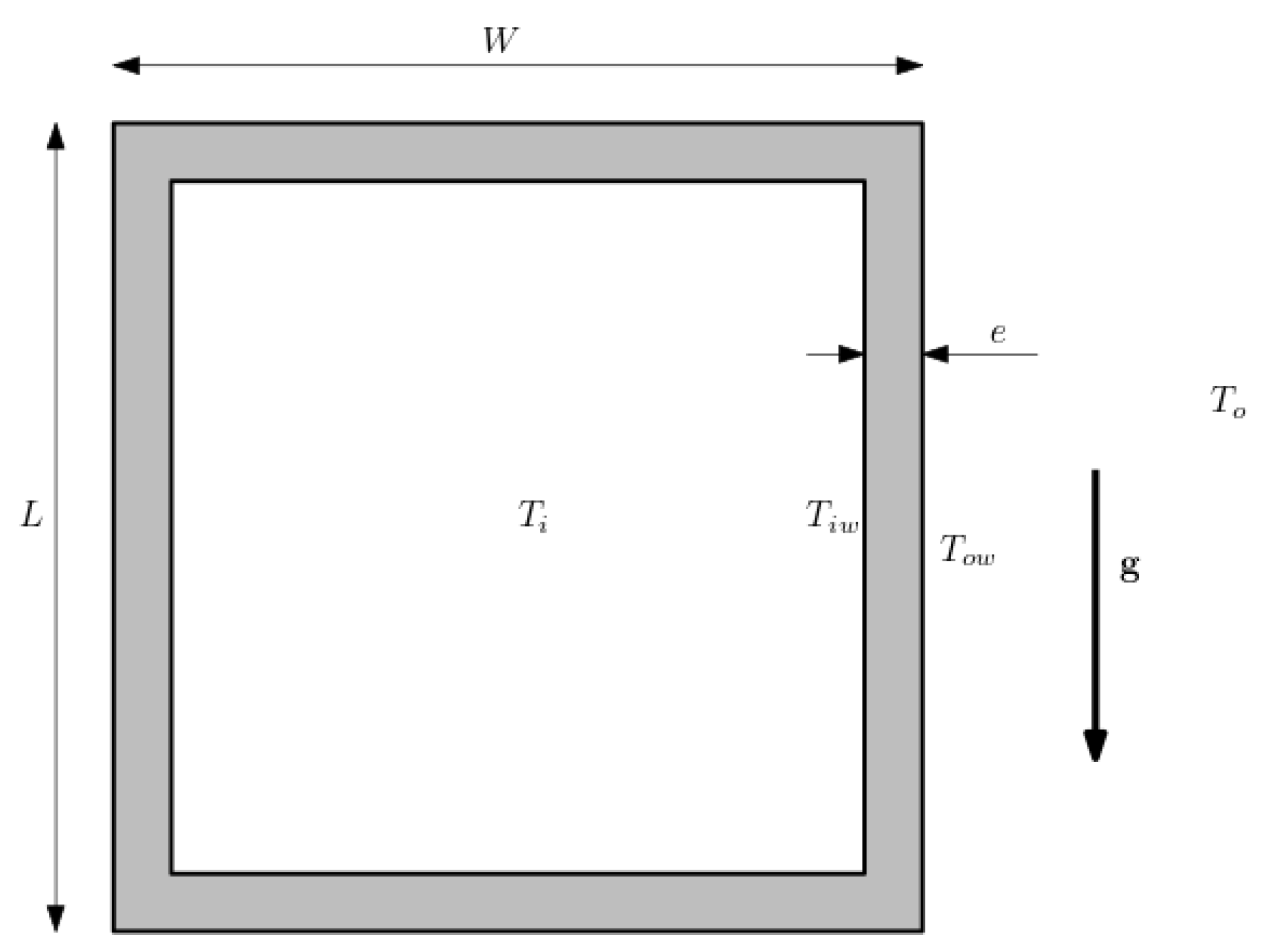
Figure 2.
Flowchart for the semi-empirical computation of the transmittance of the AHU. Different factors as conduction and forces connection, natural convection, thermal bridge and radiation are indicated with corresponding colors. In the right side of some computations the corresponding equation in the text is indicated between brackets.
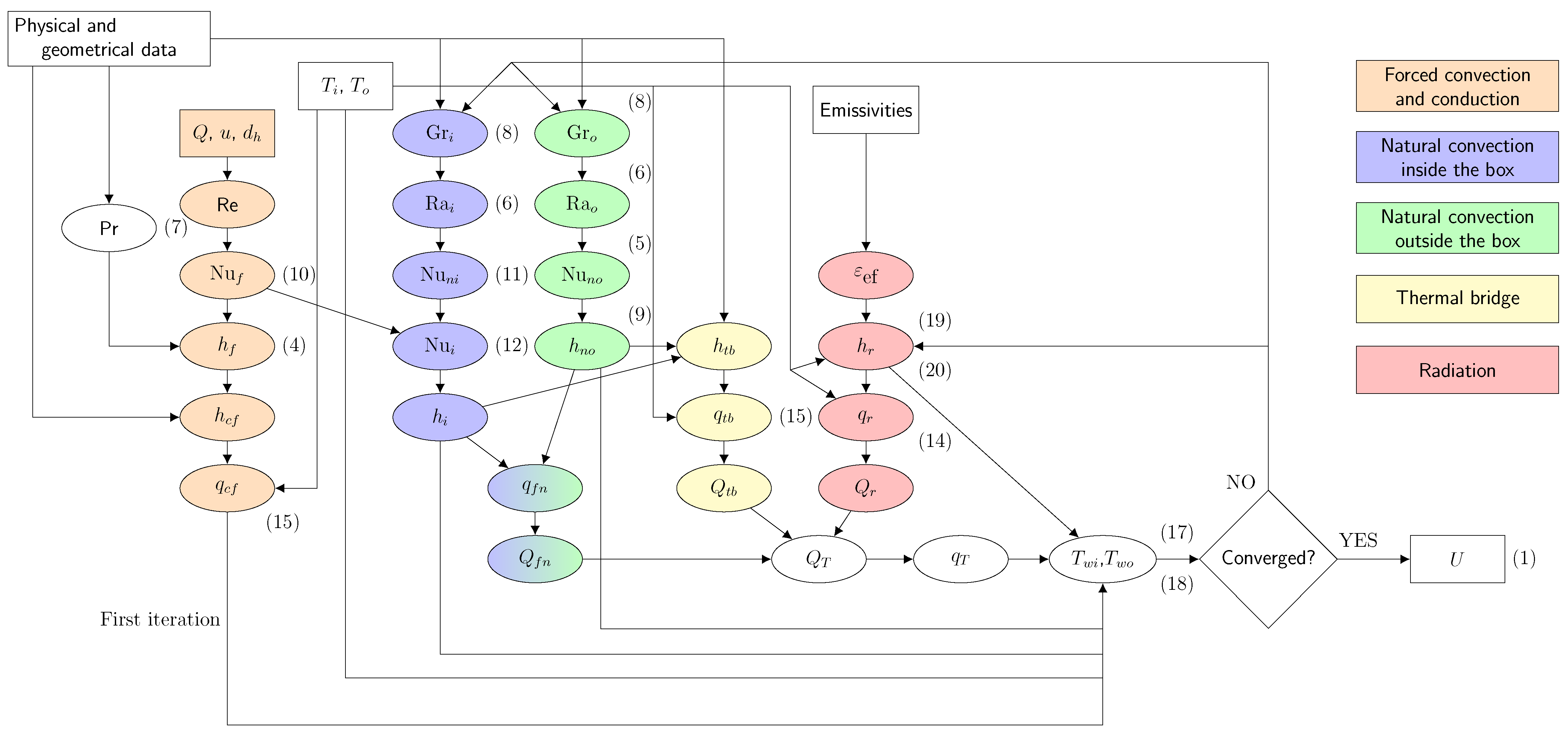
Figure 3.
Regions of the computational domain. Metal sheets enclosing the insulation are not shown due to its small width. Gravity acceleration is also shown.
Figure 3.
Regions of the computational domain. Metal sheets enclosing the insulation are not shown due to its small width. Gravity acceleration is also shown.
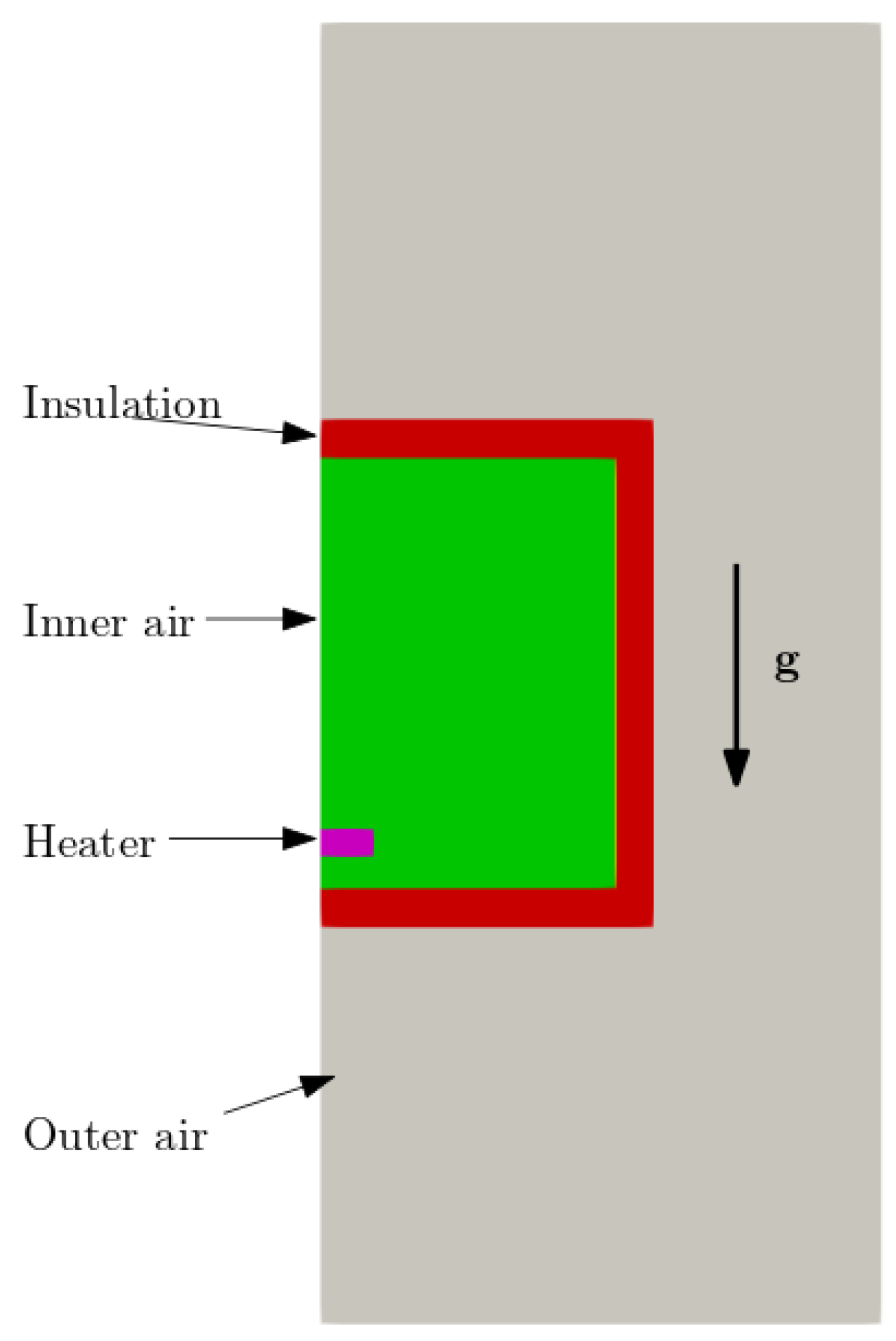
Figure 4.
Scheme of the experimental rig for the estimation of the transmittance.
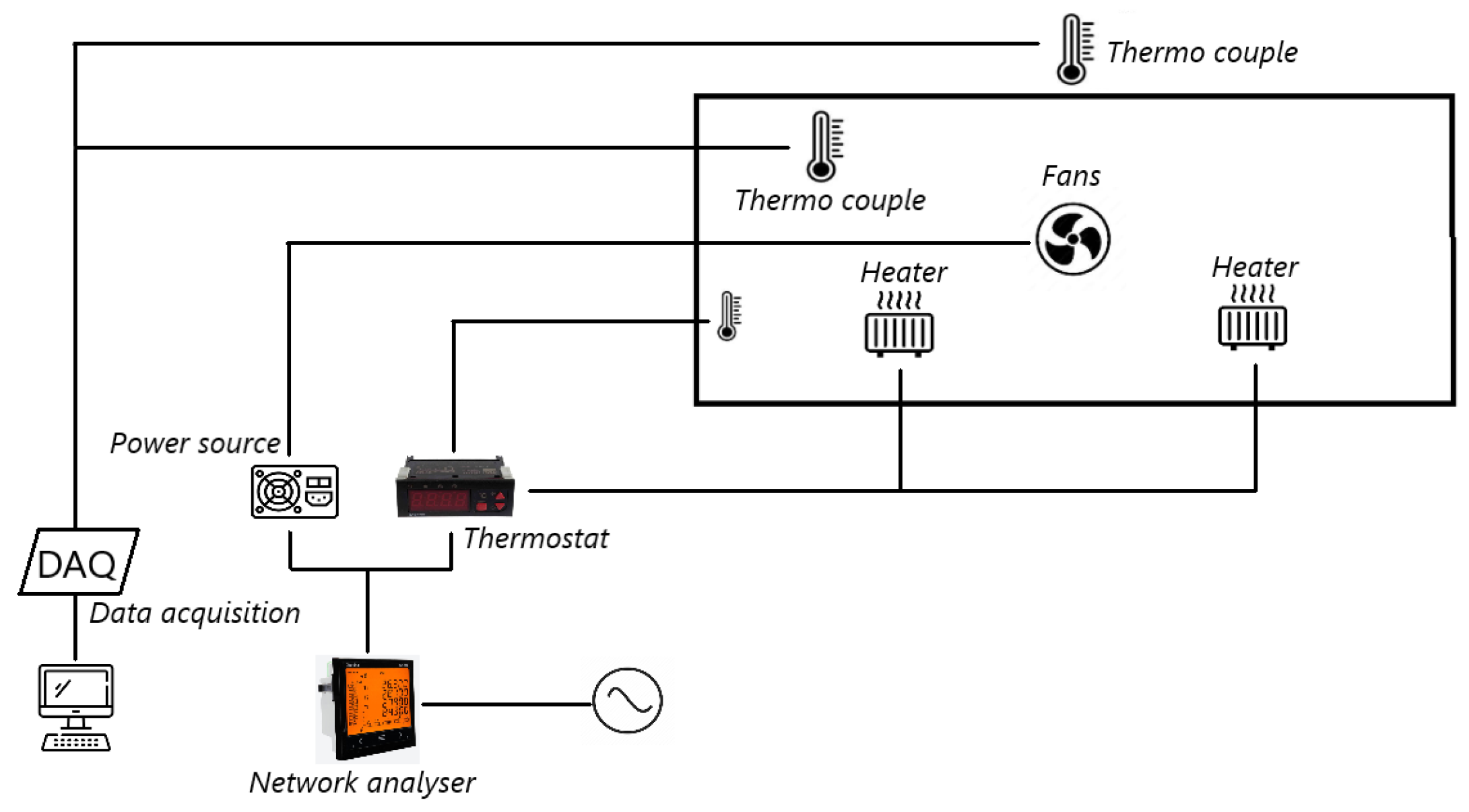
Figure 5.
Internal (red points) and external (green points) thermocouple distribution of the AHU.
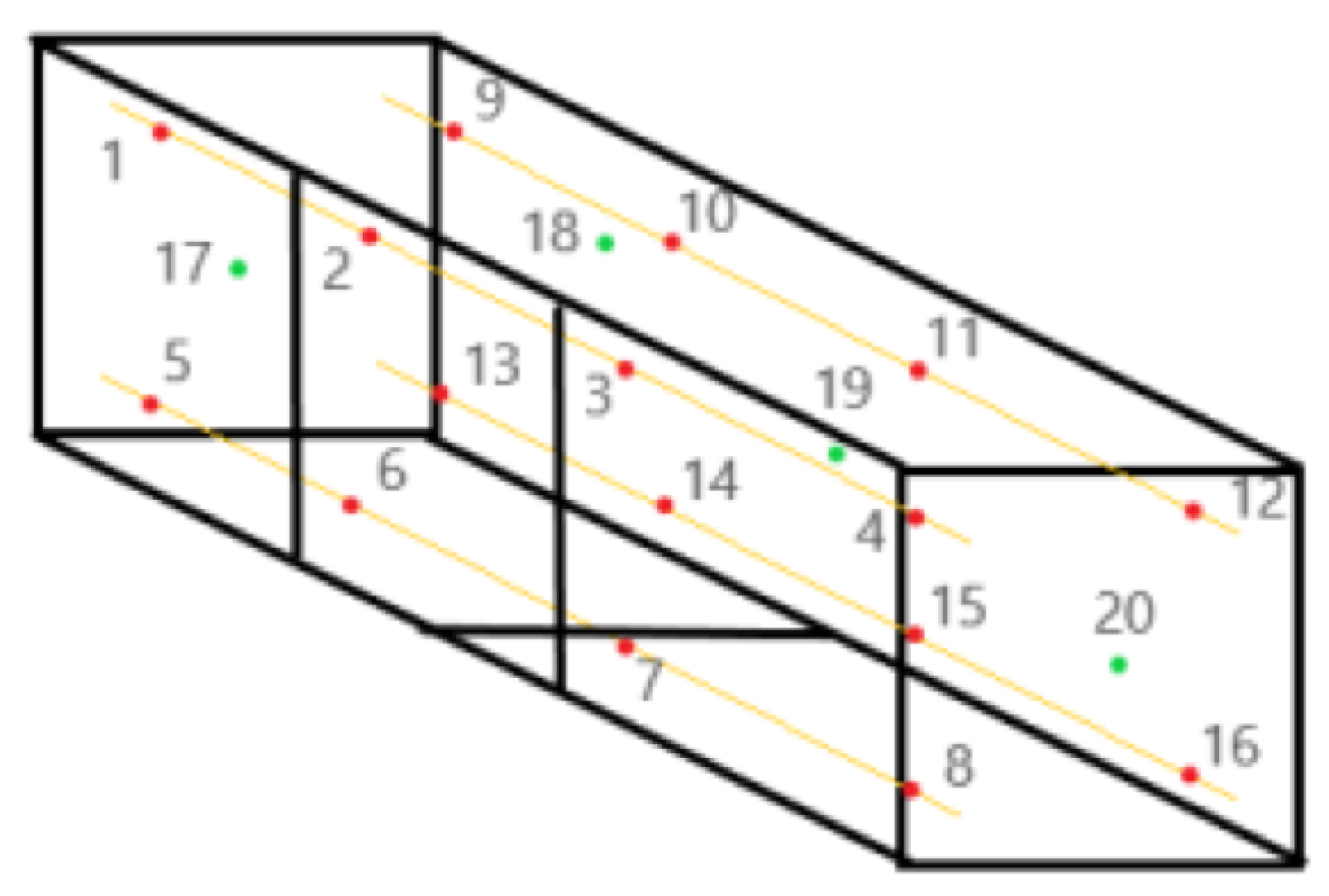
Figure 6.
Comparison of the velocity field. Units are in m/s
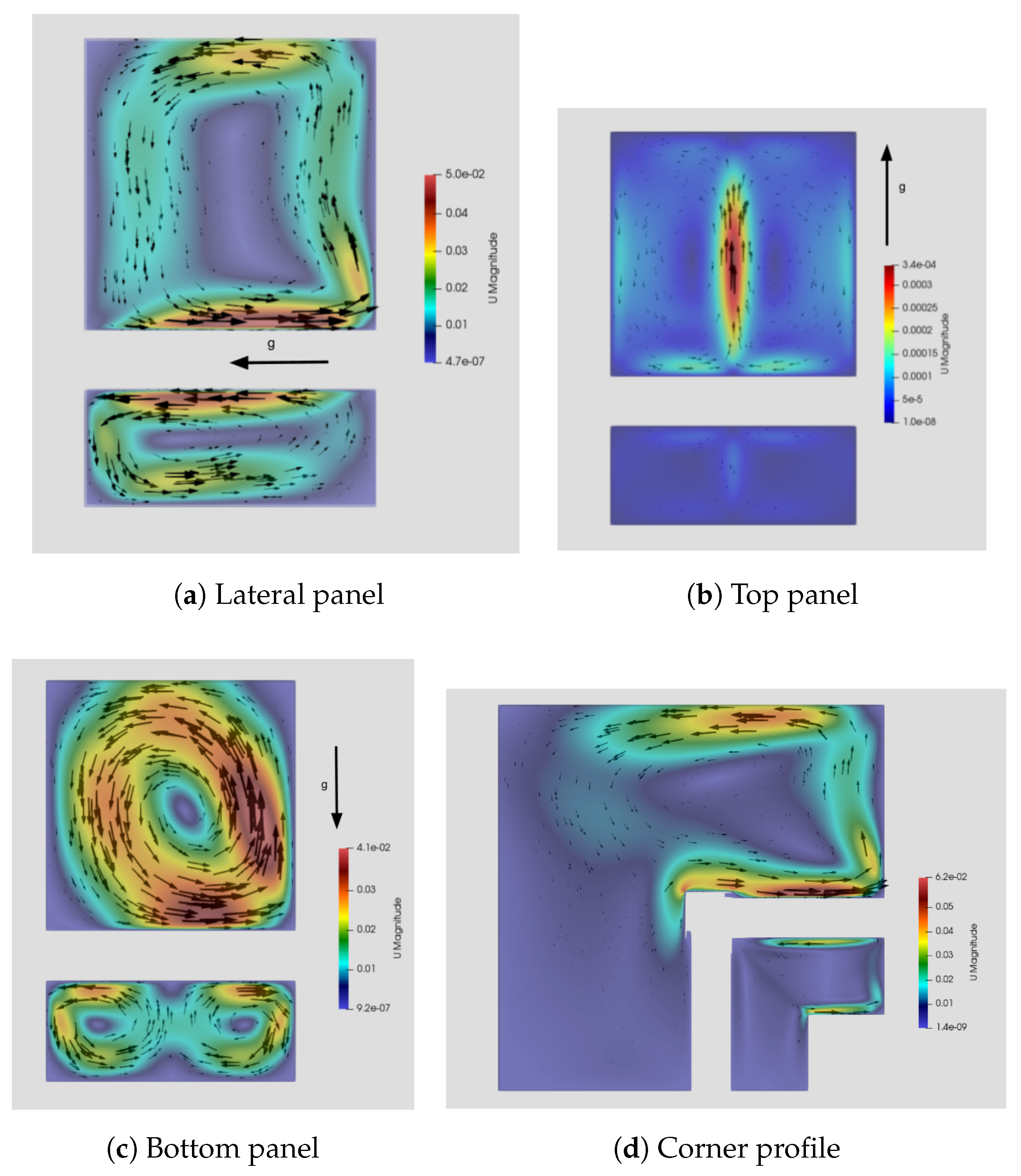
Figure 10.
Bar plot of transmittance and thermal bridge factor for the experimental measurements, theoretical estimation and numerical computation. Units of transmittance are W/(m2K). Thermal bridge factor is dimensionless.
Figure 10.
Bar plot of transmittance and thermal bridge factor for the experimental measurements, theoretical estimation and numerical computation. Units of transmittance are W/(m2K). Thermal bridge factor is dimensionless.

| c | n | ||
|---|---|---|---|
| Vertical wall | 0.59 | 1/4 | |
| Vertical wall | 0.13 | 1/3 | |
| Horizontal wall facing upwards | 0.54 | 1/4 | |
| Horizontal wall facing upwards | 0.14 | 1/3 | |
| Horizontal wall facing downwards | - | 0.27 | 1/3 |
Table 2.
Grid comparison.
| Fine | Middle | Coarse | |
|---|---|---|---|
| Number of cells | 121.875 | 60.150 | 30.850 |
| Heat transfer (from insulation to interior) |
9.1834 W/K | 9.2087 W/K | 9.2547 W/K |
Table 3.
Heat transfer results for semi-empirical estimation and numerical simulations without considering radiation effects
Table 3.
Heat transfer results for semi-empirical estimation and numerical simulations without considering radiation effects
| Method | Thermal transmittance (U) | Thermal bridge factor () |
|---|---|---|
| Semi-empirical | 0.858 | |
| CFD | 0.840 |
Table 4.
Heat transfer results with radiation
| Method | Thermal transmittance (U) | Thermal bridge factor () |
|---|---|---|
| Semi-empirical | 0.78 | |
| Experimental | 0.81 | |
| CFD | 0.79 |
Disclaimer/Publisher’s Note: The statements, opinions and data contained in all publications are solely those of the individual author(s) and contributor(s) and not of MDPI and/or the editor(s). MDPI and/or the editor(s) disclaim responsibility for any injury to people or property resulting from any ideas, methods, instructions or products referred to in the content. |
© 2025 by the authors. Licensee MDPI, Basel, Switzerland. This article is an open access article distributed under the terms and conditions of the Creative Commons Attribution (CC BY) license (http://creativecommons.org/licenses/by/4.0/).
Copyright: This open access article is published under a Creative Commons CC BY 4.0 license, which permit the free download, distribution, and reuse, provided that the author and preprint are cited in any reuse.


