
Submitted:
28 March 2025
Posted:
31 March 2025
You are already at the latest version
Abstract
(1) Background: An exoskeleton and its wearer form a mutually dependent biome-chanical system, where design choices for the exoskeleton can affect the wearer in complex and often unforeseeable ways, and this makes exoskeleton design challenging. Advanced simulation methods provide an insight into the consequences of design choices, but such analysis is usually employed towards the end of the design process. This paper demonstrates an option for musculoskeletal simulation to be used already in the conceptual design phase. (2) Methods: We present the workflow by means of an example of box lifting. We show that the mathematical algorithm underlying the solu-tion of the redundant equilibrium equations in musculoskeletal modeling has a struc-ture that can be exploited to gain information about ideal actuator forces for an exo-skeleton supporting the selected work task. (3) Results: Based on the identified forces, passive or active actuators can be selected, and control strategies can be devised. (4) Conclusions: We conclude that this methodology can save design cycles and improve exoskeleton development.
Keywords:
exoskeleton
; musculoskeletal
; simulation
; design
; knee
; spine
1. Introduction
Passive exoskeletons are wearable devices characterized by the absence of energy input from motors and usually also absence of control systems. They support the human body by structures through which forces can flow around and offload anatomical joints, and by allowing energy to be stored temporarily in elastic elements for subsequent release to level peak muscle loads. For a comprehensive classification of industrial exoskeleton types, please refer to [1].
Technical simplicity and potentially inexpensive production have enabled passive exoskeletons to penetrate the market for assistance of manual labor tasks. Typical applications are in the construction and production industries, where some work tasks involve repetitive motion of limbs and tools against gravity, for instance in painting or drywall mounting, and in warehouse or delivery work involving handling of boxes and other goods as in Figure 1, which will serve throughout this paper to exemplify the presented generally applicable methodology.
Due to passive exoskeletons’ lack of net energy input, they can only have supportive functions and/or level peak power exertion. The combination of added mass and zero energy input means that they cannot decrease the total mechanical energy consumption of a work task. However, levelling the maximal effort by releasing elastic energy stored in springs can potentially decrease the metabolic energy consumption, because even negative mechanical muscle work requires positive metabolic energy input. Ideally, elastic energy is stored in the springs during sequences of negative mechanical work. To avoid increase of muscle effort in these sequences, the power transfer to the springs should not exceed the negative mechanical power.
These physics-based limitations of passive exoskeletons narrow the window of opportunity for their use and require additional care in the combination of exoskeleton design and intended application field. The exoskeleton and human body form a combined mechanical system, where the human body with its control system and safety requirements is by far the more complicated part. The design task must consider the entire system and the mutual influence between the anatomical body and the exoskeleton, and so must simulation methods employed in the process. In this paper we illustrate how musculoskeletal simulation methods can be exploited in the conceptual design of an exoskeleton for a typical industrial work task illustrated by the example of Figure 1.
1.1. Simulation-Based Design
Living human bodies working in concert with environments, such as exoskeletons, can be simulated by software systems for musculoskeletal modeling. We shall use an inverse dynamics simulation paradigm implemented in the AnyBody Modeling System (AnyBody Technology, Aalborg, Denmark) [2]. For exoskeleton modeling, this system has the advantage of a cartesian multibody formulation [3], which can cope with the closed kinematic loops typically formed in the connectivity between the exoskeleton and the human. The technology can simulate ground reaction forces with good accuracy for a broad class of movements [4].
In the broader context of computer-aided engineering (CAE), simulation is mainly useful in the later stages of the design process, since a model cannot be created until there is a design to simulate. In this function, musculoskeletal simulation can, for instance, be used to adjust details or assistance settings [5], to derive torque controllers for active exoskeletons [6], to select among different design options [7], or to optimize exoskeleton design [8,9,10]. However, musculoskeletal simulation can also be applied early in the exoskeleton design process. Agarwal et al. [11] demonstrated an iterative approach in which virtual moments were applied to offload joints and used stepwise to infer the design of an exoskeleton for dumbbell lifting. This is remarkable, because decisions in the early part of the design process tend to commit the larger part of the total product cost [12]. In this paper we demonstrate that this process can be automated and applied to full body working tasks, if a particular structure in its underlying mathematical formulation is exploited.
2. Methods
In the inverse dynamics paradigm, the dynamic equilibrium equations take the form of a mathematical program [13]:
Minimize
subject to
where vector f = {f(M), f(R)}T contains the unknown forces in the system, separated into nm muscle forces (M) and joint reactions (R). The right-hand side, r, contains externally applied forces and velocity-dependent forces that are known when the kinematic analysis is completed, p is the power of the convex combination that forms the objective function, and C is the coefficient matrix of the equilibrium equations. Normalization factors, Ni, express the strength of the ith muscle. Depending on the value of p, the mathematical programming problem can be solved efficiently by a variety of convex programming algorithms.
We notice that forces of the mathematical program (1)-(3) separate into three categories:
- The right-hand side forces, r. These forces can be specified as any time-varying function, including exoskeleton actuator forces, and they can be applied anywhere in the system without further complicating the problem.
- The reaction forces (and moments), f(R). These are dependent variables determined by equilibrium, and they can take on any positive or negative value necessitated by the equilibrium.
- The muscle forces, f(M), which are affiliated with perceived effort and restricted in sign as shown in (3), because muscles can only pull.
Forces from categories 1 and 2 do not appear in the objective function, so they are costless. However, they do influence the objective function indirectly, because they influence the equilibrium for better or worse from the point-of-view of the muscles. Muscle forces (category 3), on the other hand, directly influence the cost of the objective function. In order of priority, the algorithm will (i) honor the specified values of right-hand side forces in category 1 while (ii) minimizing muscle forces in category 3 at the expense of (iii) costless reaction forces from category 2. In other words, the algorithm will return the values of reaction forces that minimize the muscle effort. The optimization problem (1)-(3) can therefore be perceived as a minimum effort or laziness criterion [13,14].
In the formulation of the biomechanical system, the user can place forces in the different categories, and this opportunity can be exploited to gain knowledge about favorable exoskeleton design decisions. Specifically, if exoskeleton actuator forces are placed in category 2, they will automatically attain the most favorable values in terms of reduction of muscle effort. These values can subsequently be studied and used to select an actual actuator and its control strategy. Once selected, its characteristics can be placed in category 1 for verification of the effect. This technique will be illustrated in the subsequent sections by means of an example.
We consider a typical warehouse task of lifting a box as illustrated in Figure 1. The box dimensions are 0.53m wide by 0.40m high by 0.36m deep, and its mass is 10kg. The box is held by hand slots cut out in its sides. Informed consent was obtained before the study, which did not require explicit ethical permission under the rules of the Regional Ethical Review Board of Northern Jutland.
The test subject was a healthy male, age 29, stature 1.89m, body weight 82kg, and he lifted the box from the floor to a shelf at the height of 1.58m after taking a step forward. The test subject was wearing an Xsens Awinda motion capture system (Xsens, Enschede, the Netherlands). The Awinda system is wireless and allows for the measurement to take place in-situ at the workplace. The motion was recorded and saved as a BVH file for import into the AnyBody Modeling System, where the musculoskeletal analysis was subsequently performed, including simulation of the ground reaction forces [4]. The human body model was imported from the AnyScript Managed Model Repository [15]. The combination of software and models has been validated repeatedly for spine and lower extremity simulations [16,17,18,19,20,21,22,23,24,25].
As a baseline comparison, a model of body forces in normal gait was also created and analyzed based on the argument that walking steps for healthy humans is considered a safe and even beneficial motion that can be repeated thousands of times daily without negative side effects. The experimental protocol was previously described in detail [26].
3. Simulation-Based Design
As illustrated in Figure 1, the model has a significant level of detail, and it returns thousands of muscle forces and joint reactions, which could be compared systematically between the lifting model and the baseline gait model to identify anatomical structures that are prone to overloading. For the purpose of illustrating the workflow, we selected just two joint reaction forces, namely the compression force between the patella and the femur on each leg and the compression force between the fifth lumbar vertebra, L5, and the sacrum, S1 (Figure 2). These forces were selected because they peaked at respectively three and four times of the values for a normal gait cycle and could potentially cause injury if repeated many times over a work life.
2.1. Conceptual Knee Exoskeleton Design
Based on the selected joint reaction forces, the initial analysis indicates that an exoskeleton for this work task should offload knees and the spine, and since these are different body parts, an obvious initial approach would be to design two exoskeleton components for the two knees and one for the spine.
We begin with the knees and add to the model costless reaction moments, i.e., category 2, for knee extension. In the context of the dynamic equilibrium equations (1)-(3), these become motors that will perfectly offload the knee extensor musculatures. The motors’ moment contributions are shown in Figure 3 as functions of the knee angles. It is not surprising that such an idealized knee extension contribution almost eliminates the patella-femoral forces as shown in Figure 4. The small remaining patella-femoral forces are due to activation of the bilateral rectus femoris muscle. We see from Figure 3 that, although the ideal motor compensations for knee extension moments are complicated, both motor moments can be reasonably approximated by a single linear trend line. This means that approximate knee moment compensation can be achieved by a linear torsional spring with stiffness indicated by the slope of the trend line, i.e., 1.38 Nm/degree. To avoid any action of the springs in the upright posture, we set the neutral position to zero degrees knee flexion. Replacement of the idealized motors in the model (category 2) with such springs (category 1) results in the patella-femoral forces depicted in Figure 5. As expected, this intervention has no influence on the spinal forces, but the patella-femoral forces in both legs are drastically reduced, despite the crude approximation by simple, linear springs.
The initial placement of the exoskeleton’s knee extension moments among the dependent reaction forces of category 2 allowed us to arrive at optimal spring parameters in a single iteration. In the absence of musculoskeletal simulation, this progress would have required physical user tests and production of prototypes with multiple spring configurations.
2.2. Knee and Spine Exoskeleton
At this point of the design process, it would be obvious to repeat the methodology for the spine, i.e., equip the three-dimensional rotations between the pelvis and the thorax with idealized motors, examine the relationship between angles and required support moments, and design a passive, spring-loaded upper body exoskeleton based on these specifications. However, designing a three-degree-of-freedom exoskeleton for the spine is significantly more complicated than a single degree-of-freedom spring for the knee. Furthermore, we notice from Figure 2 that the patella-femoral forces and the spinal compression forces peak simultaneously in the beginning of the movement, where Figure 1 shows that the knees and the spine are simultaneously flexed. From this knowledge, we conceive the idea that a multiarticular exoskeleton spanning the knees and lumbar spine simultaneously may be a simpler solution for both body parts.
This can be obtained by bilateral rods spanning points on the shank and thorax as depicted in Figure 6. The distal parts of the shanks have relatively little soft tissue and are well-suited for anchoring such rods, for instance to special-made boots, while harness-like straps can affix the proximal ends of the rods on the thorax.
In the formalism of the multibody simulation system, these rods represent measurable degrees-of-freedom to which reaction forces, i.e., forces of category 2, can be assigned. This simultaneously offloads the spine and knees as shown in Figure 7. We notice that the potential for knee offloading is significant, albeit smaller than with the designated knee exoskeleton. We also notice that the spinal compression is drastically reduced and now peaks in the last third of the movement.
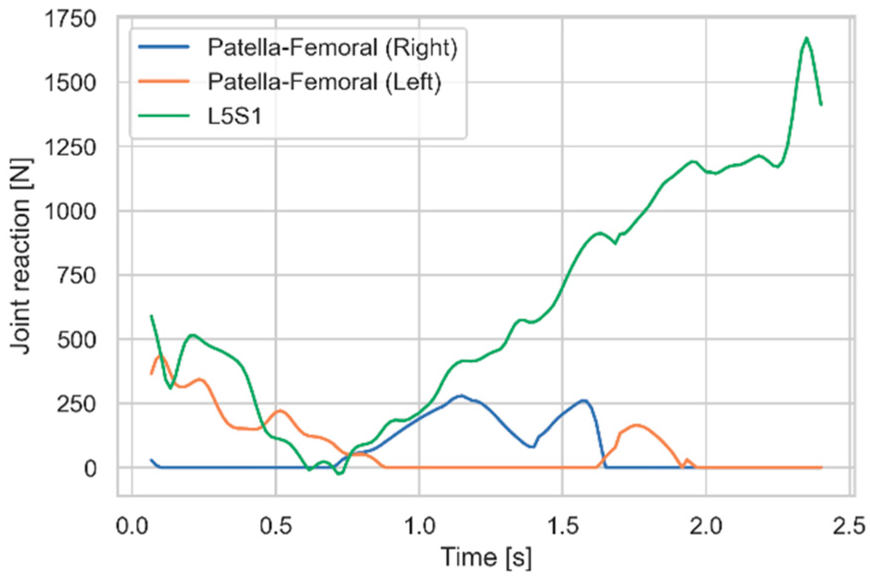
Figure 8 shows the relationship between idealized rod forces and rod length. We see that the relationship is close to linear, except for a sharp increase towards the end of the movement. However, the latter applies to the upright standing posture for which Figure 2 revealed that there was little need for support, and we can consequently disregard this part and create a common trend line only for the descending parts of the two curves in Figure 8. This trend line has a slope of -604 N/m, which is the ideal spring constant, and it crosses the first axis at rod length 1.57m, which is therefore the ideal slack length of the spring. Replacing the idealized motor (category 2) in the rods with springs (category 1) of these characteristics yields the joint reaction forces of Figure 9, which in comparison with Fig 2 shows reduction of all the reaction forces of interest.
4. Discussion
The example demonstrated how a systematic approach to musculoskeletal simulation can spark ideas for exoskeleton design and allow the designer to arrive at optimal design parameters in a single or a few iterations performed in-silico. The general nature of the approach indicates that it has potential to be used for design scenarios beyond the chosen example.
The presented methodology tends to minimize muscle exertion rather than joint loads because the objective function (1) is formulated in terms of forces. However, because more of the joint load in the human body is typically generated by muscle actions than by external forces, design choices that minimize muscle effort will also tend to reduce joint reaction forces, as we saw in the example. It should be noted, though, that the offloading of some body parts by an exoskeleton may lead to increased loads on other body parts, so a practical design process should consider body loads more comprehensibly than what was demonstrated here.
Other examples may reveal situations where no approximately linear relationship between a degree-of-freedom and the required force can be identified, in which case the design task would include creation of nonlinear forces and/or active actuator strategies. This obviously leads to more complicated designs, but the insight would enable the designer to quickly move on from the search for linear spring solutions to more advanced options.
The reliance on inverse dynamics simulation causes the inherent assumption that the movement is independent of the presence of the exoskeleton, i.e., after donning the exoskeleton, the user will complete the work task exactly as it was measured in the first place. This is likely false to some extent and is a limitation of the method that is hard to mitigate, until a physical prototype has been created much later in the process. Only practical experience with the method in real design processes can reveal whether this limitation is problematic.
Whether the exemplified exoskeleton concept will work in practice can only be investigated by further design iterations and physical tests. One of the inherent drawbacks of multiarticular exoskeleton concepts is their space requirement and the possible interference with movements and work tasks for which they were not directly designed. Furthermore, bulky exoskeletons may collide with obstacles in the environment and scratch or dent products and production facilities. The proposed solution has the advantage of passing close to the sides of the body with slack springs in the upright posture, but it may become a nuisance in crouched postures other than the initial stages of box lifting. In gait, the rods will be subjected to the acceleration forces of the moving legs, so subsequent design iterations should endeavor to limit the mass of the rods as much as possible and prevent them from wobbling during walking.
5. Conclusions
Musculoskeletal simulation of work tasks from manual materials handling holds a potential to speed up exoskeleton design cycles, identify optimally offloading solutions, and potentially reduce the cost of the product committed by early design decisions. Practical application of the method is necessary to further clarify its potential.
Funding
This research received no external funding.
Informed Consent Statement
Informed consent was obtained from the test subject.
Data Availability Statement
Binary data files on hd5 format containing analysis results are available at https://doi.org/10.5281/zenodo.15082694 [27].
Conflicts of Interest
The author owns stock in AnyBody Technology A/S, whose software was used for the simulation.
Abbreviations
The following abbreviations are used in this manuscript:
| CAE | Computer/Aided Engineering |
References
- de Looze, M.P.; Bosch, T.; Krause, F.; Stadler, K.S.; O’Sullivan, L.W. Exoskeletons for Industrial Application and Their Potential Effects on Physical Work Load. Ergonomics 2016, 59, 671–681. [Google Scholar] [CrossRef]
- Damsgaard, M.; Rasmussen, J.; Christensen, S.T.; Surma, E.; de Zee, M. Analysis of Musculoskeletal Systems in the AnyBody Modeling System. Simul Model Pract Theory 2006, 14. [Google Scholar] [CrossRef]
- Nikravesh, P.E. Computer-Aided Analysis of Mechanical Systems; Prentice-Hall, Inc., 1988; ISBN 0131642200.
- Skals, S.; Jung, M.K.; Damsgaard, M.; Andersen, M.S. Prediction of Ground Reaction Forces and Moments during Sports-Related Movements. Multibody Syst Dyn 2017, 39, 175–195. [Google Scholar] [CrossRef]
- Seiferheld, B.E.; Frost, J.; Krog, M.; Skals, S.; Andersen, M.S. Biomechanical Investigation of a Passive Upper-Extremity Exoskeleton for Manual Material Handling - a Computational Parameter Study and Modelling Approach. International Journal of Human Factors Modelling and Simulation 2022, 7, 275. [Google Scholar] [CrossRef]
- Cardona, M.; García Cena, C.E.; Serrano, F.; Saltaren, R. ALICE: Conceptual Development of a Lower Limb Exoskeleton Robot Driven by an on-Board Musculoskeletal Simulator. Sensors (Switzerland) 2020, 20. [Google Scholar] [CrossRef]
- Alabdulkarim, S.; Kim, S.; Nussbaum, M.A. Effects of Exoskeleton Design and Precision Requirements on Physical Demands and Quality in a Simulated Overhead Drilling Task. Appl Ergon 2019, 80, 136–145. [Google Scholar] [CrossRef]
- Grabke, E.P.; Masani, K.; Andrysek, J. Lower Limb Assistive Device Design Optimization Using Musculoskeletal Modeling: A Review. Journal of Medical Devices, Transactions of the ASME.
- Zhou, L.; Li, Y.; Bai, S. A Human-Centered Design Optimization Approach for Robotic Exoskeletons through Biomechanical Simulation. Rob Auton Syst 2017, 91, 337–347. [Google Scholar] [CrossRef]
- Ostraich, B.; Riemer, R. Rethinking Exoskeleton Simulation-Based Design: The Effect of Using Different Cost Functions. IEEE Transactions on Neural Systems and Rehabilitation Engineering 2024, 32, 2153–2164. [Google Scholar] [CrossRef]
- Agarwal, P.; Narayanan, M.S.; Lee, L.-F.; Mendel, F.; Krovi, V.N. Simulation-Based Design of Exoskeletons Using Musculoskeletal Analysis, 2010.
- Weustink, I.F.; ten Brinke, E.; Streppel, A.H.; Kals, H.J.J. A Generic Framework for Cost Estimation and Cost Control in Product Design. J Mater Process Technol 2000, 103, 141–148. [Google Scholar] [CrossRef]
- Rasmussen, J.; Damsgaard, M.; Voigt, M. Muscle Recruitment by the Min/Max Criterion - A Comparative Numerical Study. J Biomech 2001, 34. [Google Scholar] [CrossRef]
- Crowninshield, R.D. Use of Optimization Techniques to Predict Muscle Forces. J Biomech Eng 1978, 100, 88–92. [Google Scholar] [CrossRef]
- Lund, M.E.; Tørholm, S.; Jensen, B.K.; Galibarov, P.E.; Dzialo, C.M.; Iversen, K.; Sarivan, M.; Marra, M.A.; Simonsen, S.T. The AnyBody Managed Model Repository (AMMR) 2020.
- Marra, M.A.; Vanheule, V.; Fluit, R.; Koopman, B.H.F.J.M.; Rasmussen, J.; Verdonschot, N.; Andersen, M.S. A Subject-Specific Musculoskeletal Modeling Framework to Predict in Vivo Mechanics of Total Knee Arthroplasty. J Biomech Eng 2015, 137. [Google Scholar] [CrossRef]
- Stambolian, D.; Eltoukhy, M.; Asfour, S. Development and Validation of a Three Dimensional Dynamic Biomechanical Lifting Model for Lower Back Evaluation for Careful Box Placement. Int J Ind Ergon 2016, 54, 10–18. [Google Scholar] [CrossRef]
- Bassani, T.; Stucovitz, E.; Qian, Z.; Briguglio, M.; Galbusera, F. Validation of the AnyBody Full Body Musculoskeletal Model in Computing Lumbar Spine Loads at L4L5 Level. J Biomech 2017, 58. [Google Scholar] [CrossRef]
- Bassani, T.; Stucovitz, E.; Quian, Z.; Briguglio, M.; Galbusera, F. Assessment of the Anybody Full Body Musculoskeletal Model in Computing Spine Loads at Lumbar Level: Comparison With in Vivo Values Obtained During Exercise Tasks. ScienceOpen Posters 2020. [Google Scholar] [CrossRef]
- Ignasiak, D. A Novel Method for Prediction of Postoperative Global Sagittal Alignment Based on Full-Body Musculoskeletal Modeling and Posture Optimization. J Biomech 2020, 102, 109324. [Google Scholar] [CrossRef]
- Liu, T.; Khalaf, K.; Adeeb, S.; El-Rich, M. Numerical Investigation of Intra-Abdominal Pressure Effects on Spinal Loads and Load-Sharing in Forward Flexion. Front Bioeng Biotechnol 2019, 7. [Google Scholar] [CrossRef] [PubMed]
- Chen, Z.; Zhang, Z.; Wang, L.; Li, D.; Zhang, Y.; Jin, Z. Evaluation of a Subject-Specific Musculoskeletal Modelling Framework for Load Prediction in Total Knee Arthroplasty. Med Eng Phys 2016, 38, 708–716. [Google Scholar] [CrossRef]
- Jung, Y.; Koo, Y.; Koo, S. Simultaneous Estimation of Ground Reaction Force and Knee Contact Force during Walking and Squatting. International Journal of Precision Engineering and Manufacturing 2017, 18, 1263–1268. [Google Scholar] [CrossRef]
- Richards, R.E.; Andersen, M.S.; Harlaar, J.; van den Noort, J.C. Relationship between Knee Joint Contact Forces and External Knee Joint Moments in Patients with Medial Knee Osteoarthritis: Effects of Gait Modifications. Osteoarthritis Cartilage 2018, 26, 1203–1214. [Google Scholar] [CrossRef]
- Dupré, T.; Dietzsch, M.; Komnik, I.; Potthast, W.; David, S. Agreement of Measured and Calculated Muscle Activity during Highly Dynamic Movements Modelled with a Spherical Knee Joint. J Biomech 2019, 84, 73–80. [Google Scholar] [CrossRef] [PubMed]
- Rasmussen, J.; Iversen, K.; Engelund, B.K.; Rasmussen, S. Biomechanical Evaluation of the Effect of Minimally Invasive Spine Surgery Compared with Traditional Approaches in Lifting Tasks. Front Bioeng Biotechnol 2021, 9. [Google Scholar] [CrossRef] [PubMed]
- Rasmussen, J.; Engelund, B.K.; Iversen, K. Musculoskeletal Simulation Results for Boxlifting with and without Conceptually Designed Exoskeletons. Zenodo 2025.
Figure 1.
A musculoskeletal model of box lifting from the floor to a shelf.
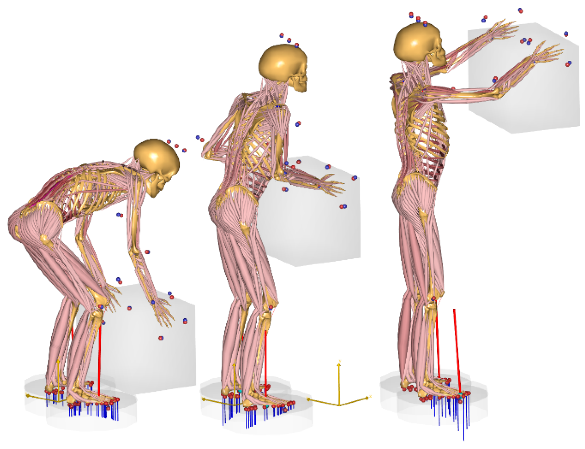
Figure 2.
Patella-femoral and L5-S1 reaction forces for the box lifting task.
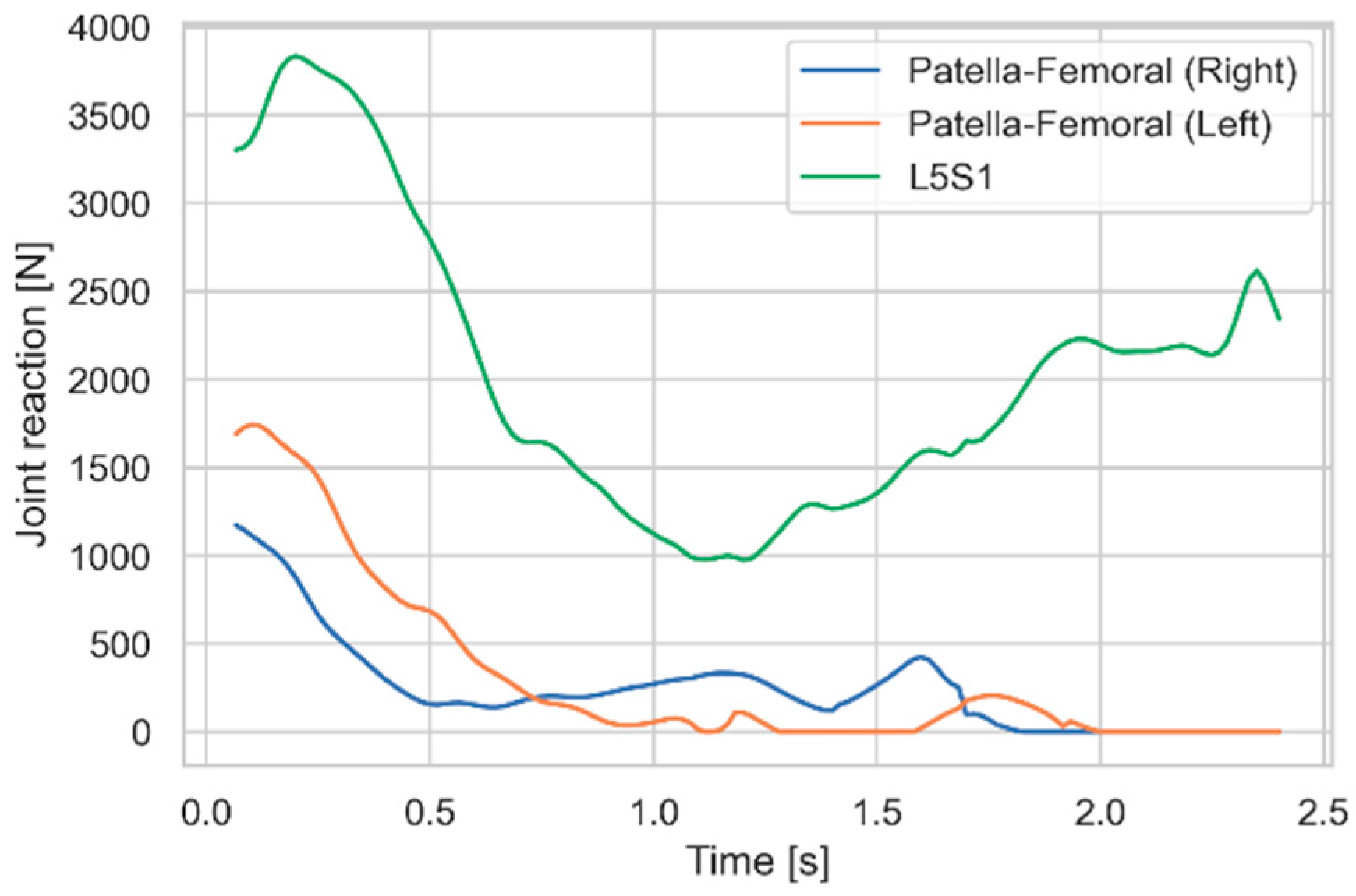
Figure 3.
Idealized knee motor extension moments as functions of the knee angles, and trend line.

Figure 4.
Patella-femoral and L5-S1 reaction forces with idealized knee extension motors.
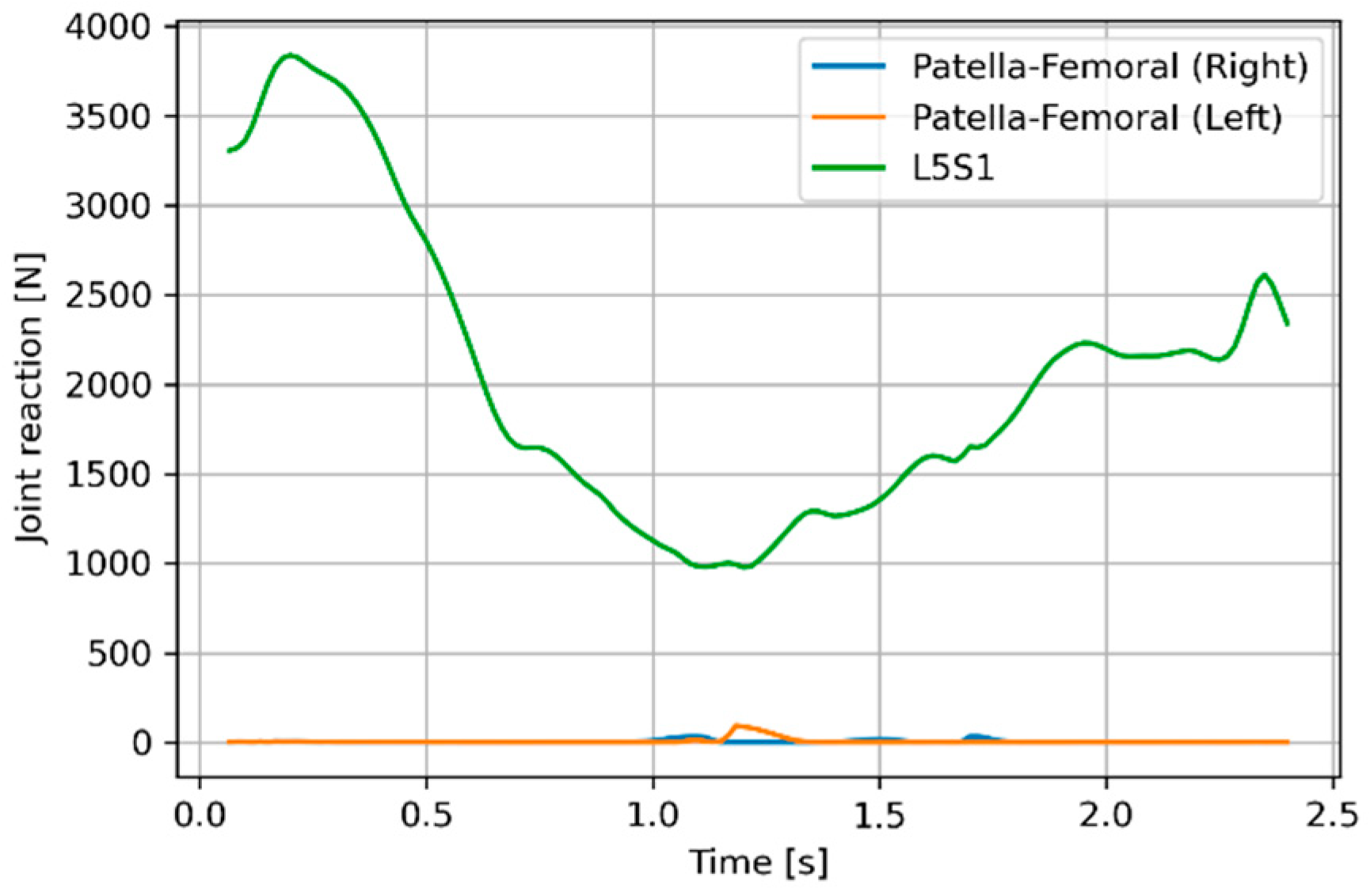
Figure 5.
Patella-femoral and L5-S1 reaction forces with a passive spring-loaded exoskeleton on the knees.
Figure 5.
Patella-femoral and L5-S1 reaction forces with a passive spring-loaded exoskeleton on the knees.
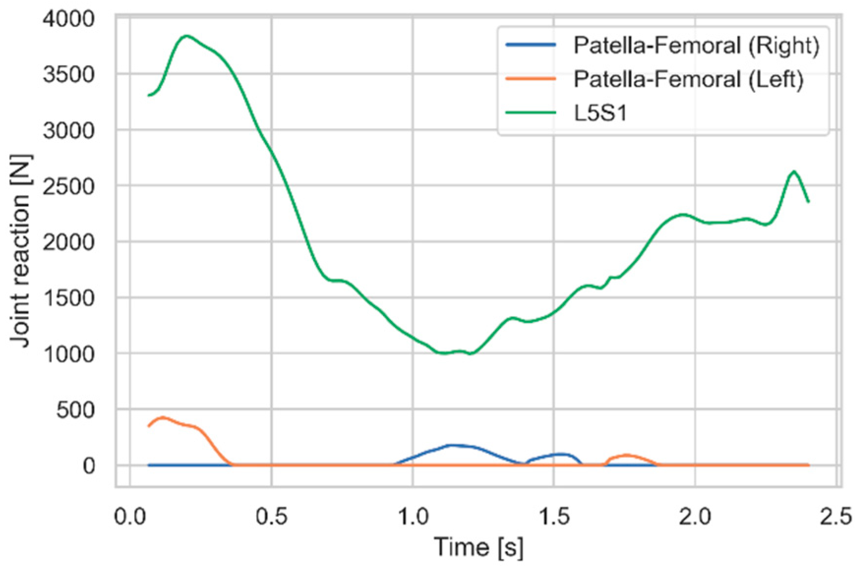
Figure 6.
Addition of bilateral rods spanning knees and the lumbar spine.
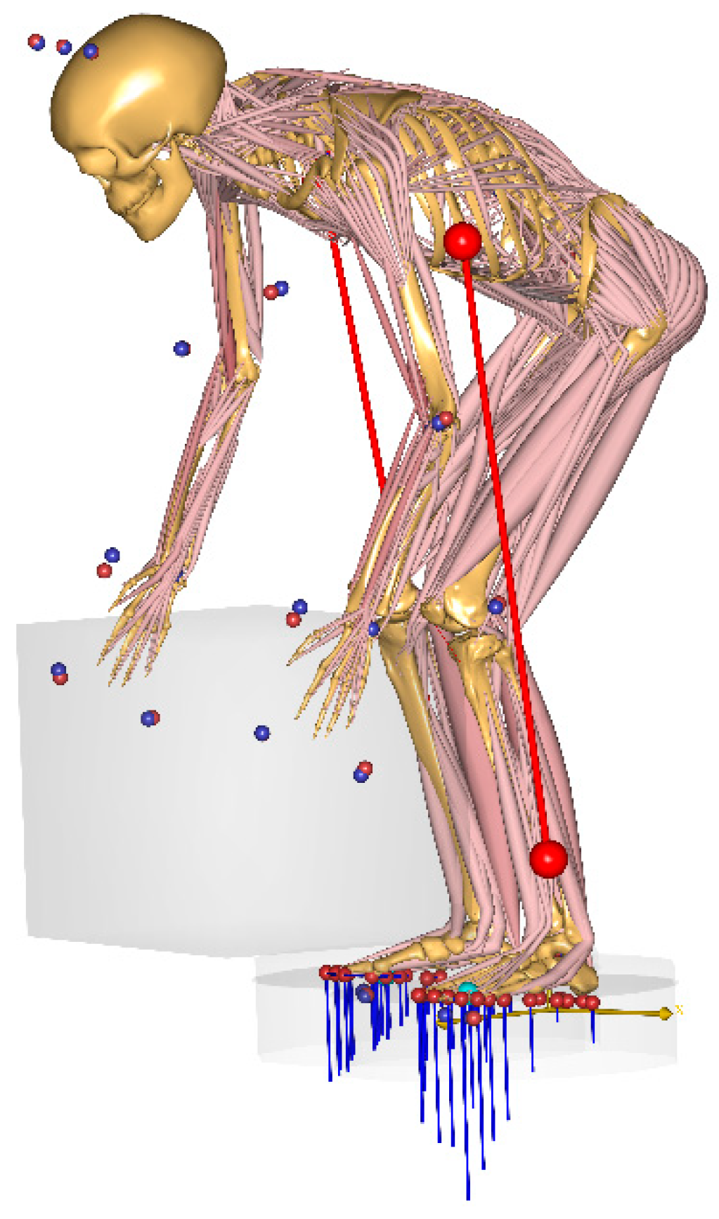
Figure 7.
Patella-femoral and L5-S1 reaction forces with idealized bilateral linear actuators.
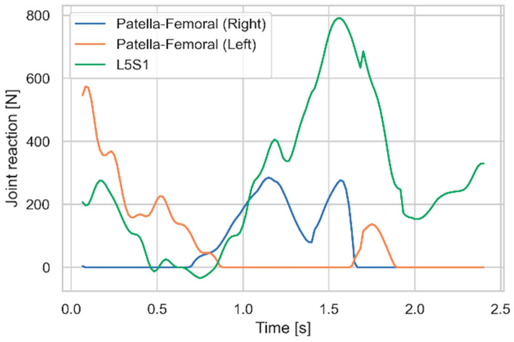
Figure 8.
Idealized rod reaction forces and a selective trend line covering only the descending part of the two curves.
Figure 8.
Idealized rod reaction forces and a selective trend line covering only the descending part of the two curves.
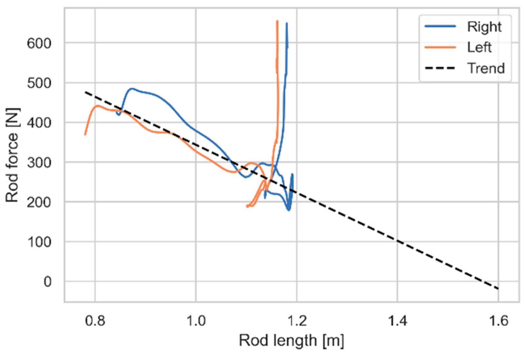
Figure 9.
Patella-femoral and L5-S1 reaction forces when supporting the body with bilateral, spring-loaded rods.
Figure 9.
Patella-femoral and L5-S1 reaction forces when supporting the body with bilateral, spring-loaded rods.
Disclaimer/Publisher’s Note: The statements, opinions and data contained in all publications are solely those of the individual author(s) and contributor(s) and not of MDPI and/or the editor(s). MDPI and/or the editor(s) disclaim responsibility for any injury to people or property resulting from any ideas, methods, instructions or products referred to in the content. |
© 2025 by the authors. Licensee MDPI, Basel, Switzerland. This article is an open access article distributed under the terms and conditions of the Creative Commons Attribution (CC BY) license (http://creativecommons.org/licenses/by/4.0/).
Copyright: This open access article is published under a Creative Commons CC BY 4.0 license, which permit the free download, distribution, and reuse, provided that the author and preprint are cited in any reuse.


