
Submitted:
27 March 2025
Posted:
27 March 2025
You are already at the latest version
Abstract
The construction industry is a major contributor to the global climate crisis, prompting increasing interest in minimising the embodied carbon of structures, whether through material production regulations or the optimisation of structural elements. While a wide body of literature addresses the reduction of embodied carbon in superstructures, limited attention has been devoted to the optimisation of foundations, particularly piles. This research introduces a hybrid genetic algorithm optimisation tool designed to minimise the embodied carbon of tension piles in different soil conditions. Six different pile types are analysed: solid and hollow concrete piles, steel pipes, UC sections, and timber piles in both square and round forms. The optimal design parameters for each pile type are presented and compared for undrained clay and loose sand. The results demonstrate the potential for reducing the embodied carbon of piles when utilising optimised designs. Finally, a case study involving an 8-metre-high crossroad signpost is presented, illustrating the practical application of the proposed optimisation algorithm in reducing embodied carbon for future designs.
Keywords:
Tension piles
; timber piles
; concrete piles
; steel piles
; optimisation
; genetic algorithm
; embodied carbon
6.1. Introduction
6.1.1. Background
The climate emergency is one of the most pressing challenges globally, with unprecedented environmental change due to excessive greenhouse gas emissions. The built environment is a main contributor to this crisis being responsible for nearly 37% of the global energy-related emissions in 2023 (United Nations Report, 2023). Material production, energy consumption for on-site machinery, material transportation, and overall construction processes are substantial sources of global carbon emissions (Hong et al., 2014). As urbanisation and the demand for infrastructure continue to increase, the construction sector’s contribution to the climate crisis rises accordingly. It is thus essential for the industry to adopt sustainable practices, including innovative design optimisation and the use of low-carbon materials, to mitigate its environmental footprint and contribute to global decarbonisation efforts (Regona et al., 2024).
Structural optimisation plays a key role in addressing the environmental challenges posed by the construction sector. By employing advanced computational techniques, structural optimisation enables the design of resource-efficient structures without compromising safety or performance. For instance, research has shown that optimising concrete structures can result in significant material savings compared to traditional designs (Gauch et al., 2022; Fang et al., 2023). For slab design, the application of structural optimisation has been found to reduce concrete use by as much as 25%, while maintaining structural integrity (Sahab, Ashour and Toropov, 2005; Faddoul and Sirivivatnanon, 2024). For concrete beams and columns, structural optimisation is a vital concept in minimising the embodied carbon of structures (Jayasinghe et al., 2021; Zhang and Zhang, 2021). Moreover, foundations account for a considerable share of any structure, therefore there has been currently an increasing interest in minimising the embodied carbon from substructures, including minimising the embodied carbon from retaining structures (Kayabekir et al., 2020; Balasbaneh and Marsono, 2020), concrete pile design (Abushama et al., 2023b; Abushama et al., 2024a), slope stability (Zhu, Zhang and Jia, 2022; Yazdani, AliPanahi and Sadeghi, 2024) and raft foundations (Sandanayake, Zhang and Setunge, 2016; Teodosio et al., 2023).
Tension piles are very common in geotechnical engineering due to their crucial role in ensuring the stability of structures subject to uplift forces, and resistance to different loading conditions including wind loads, seismic loads or even groundwater pressure (Danziger, Danziger and Pacheco, 2006; Zhou et al., 2017). Their application is particularly important in projects such as resisting uplift forces in high-rise buildings (Dickin and Leung, 1990; Shanker, Basudhar and Patra, 2007), and resisting overturning actions in bridges and offshore structures as part of pile groups (Arsoy, Duncan and Barker, 2002; Liang, Zheng and Zhang, 2020) as well as supporting static loading tests for compression piles, as shown in Figure 1 (Russo, 2013). Tension piles can also be used to reinforce soil in areas with weak or unstable soils (Zhang, Wang and Wang, 2017), or regions prone to environmental stresses such as earthquakes and flooding (Boulanger et al., 2003).
Despite the of tension piles, very limited attention is given in the literature to their optimisation. This is believed to be due to the uncertainties surrounding estimating the accurate friction resistance of piles leading to conservative designs adopting high values of factor of safety and no desire/willingness for optimisation (Lacasse et al., 2013; Bueno Aguado, Escolano Sánchez and Sanz Pérez, 2021). A laboratory investigation of 31 bored piles, 12 driven piles, and 5 vibro-driven pullout tests demonstrated that the method of pile installation has a significant influence on the ultimate tensile resistance and should be considered when designing tension piles (Levacher and Sieffert, 1984). The degradation of tension pile designs during installation was further studied using a database of 34 pullout pile load tests sourced from existing geotechnical literature, results showed that a degradation factor should be utilised in an optimal pile design (Alawneh, 1999). The degradation of offshore scour-affected tension piles was studied, and a simplified method was developed to account for various scour-hole dimensions around optimised tripod piles in offshore structures (Fazeres-Ferradosa et al., 2021). A finite element study on the use of timber piles as tension and bending resisting elements for embankment-supporting showed the effect of GLTP (geosynthetic-reinforced load transfer platform) extent, embankment height, pile spacing, GLTP configuration on the performance of optimised support systems (Ikbarieh et al., 2023). Metal screw tension piles also stand as a circular alternative to concrete tension piles, the optimisation of this type of pile has been further addressed in the literature (Al-Rawabdeh et al., 2024). Nevertheless, no available studies are recorded on optimising the environmental impact of tension piles, a gap that is addressed in this research.
6.1.2. Aims and Objectives
The authors have previously addressed optimising the embodied carbon of piles subjected to axial compression (Abushama et al., 2023b) and lateral forces (Abushama et al., 2024) as well as investigating the embodied carbon of different piling materials (Abushama et al., 2025). Results showed a strong influence of pile geometry and design parameters on the environmental impact of piles, suggesting potential room for improvement moreover, it was shown that timber piles are the most environmentally-friendly option in compression but are only suitable at low-capacity (<1.3 MN). Hollow concrete piles also were shown to be significantly more carbon-efficient than conventional solid concrete piles in all soil types.
However, no attention has been given to piles subjected to tensile stresses. Therefore, this research aims to discover the optimal concrete, steel and timber pile designs under pure tensile loads in both undrained clay and loose sand. This is achieved through the following objectives:
- i.
- Introduce a robust optimisation algorithm that is capable of producing pile designs with the lowest embodied carbon for different soil conditions and pile capacities.
- ii.
- Deploy the optimisation algorithm to discover the optimal design of six different pile types; concrete solid, concrete hollow, steel pipe, steel universal column section (UC), timber rounded and timber square in a range of common soil types.
- iii.
- Compare the characteristics of optimal tension piles to optimal compression piles, in order to provide generalised design guidance.
- iv.
- Apply the optimisation algorithm to an existing case study to assess the potential carbon saving for a built structure for future endeavours.
6.1.3. Analysis Setup
The research is structured into four sections to address the four main research objectives:
- a)
- Optimising the embodied carbon of tension piles in undrained clay soil: Concrete, steel, and timber piles with capacities up to 3 MN are designed in undrained clay conditions. The optimal design parameters for each material type are determined and compared.
- b)
- Optimising the embodied carbon of tension piles in loose sand: Concrete, steel, and timber piles are designed for capacities up to 3 MN in loose sand conditions, and the optimal design parameters are compared.
- c)
- Comparative analysis: A broad discussion is provided to compare the optimal design options for both compression and tension piles in different soil types.
- d)
- Case study: A real-world case study of an existing tension pile design is presented in detail. The parameters from the built piles are fed into the optimisation algorithm to generate an alternative optimal pile design.
6.2. Methodology
6.2.1. Pile Capacities and Soil Types
The six tested pile types comprise different materials, geometries, and specifications as shown in Section 6.2.3. A safe pile design should at least be capable of satisfying two design criteria:
- -
- Structural capacity: the pile resistance as a structural element subjected to pure tensile stresses is within a safe limit.
- -
- Geotechnical capacity: the factored pile’s frictional resistance is less than the applied tensile load.
For this study, a range of tensile pile capacities of up to 3 MN is tested. Following is a summary of the theoretical models used to assess each pile capacity.
6.2.1.1. Structural capacity
The tensile capacity of cracked concrete, steel and
timber structural elements (Ncon. , Nstl. and Ntim.) are calculated in accordance with Eurocodes
2, 3 and 5 (British Standards Institution, 2004, 2005, 2008) respectively and
are summarised as follows:
Where:
- and = steel cross-sectional area and timber cross-sectional area
- = characteristic compressive strength of timber and steel.
- = partial factor for timber compressive strength = 1.3 (British Standards Institute, 2002)
- = partial factor for steel compressive strength = 1.3 (British Standards Institute, 2002)
- n = reduction factor for timber class 3, submerged in water = 0.8 (British Standards Institute, 2004)
6.2.1.2. Geotechnical Capacity
There exist several methods for assessing the tension capacity of piles (Qt) including, but not limited to, the Alawneh method which was a result of 34 pull-out pile load tests collected from the literature, the American Petroleum Institute (API) method which is based on field experiments performed on instrumented closed-ended displacement piles (Alawneh, Husein Malkawi and Al-Deeky, 1999), and the ICP-05 design method which is based on results from load tests on jacked closed-ended instrumented piles and was calibrated for open-ended piles primarily using tests on driven piles (Lehane et al., 1993). However, one of the most commonly used and simply interpreted methods for estimating the tensile capacity of piles was proposed by De Nicola and Randolph (1993). Based on experimentation, the authors were able to calculate the tensile pile capacity (Qt) as a ratio of its surface friction resistance, under compressive loading (Qc) as shown in Equation 6.4. The results were validated against published literature including the experimental work by Kulhawy and Phoon (Kulhawy and Phoon, 1993; Knappett and Craig, 2012), and the suggested ratio was found to provide a good lower boundary for estimating the tensile strength of piles in fine soil and coarse soil as shown in Figure 2.
Where:
- -
- , and = pile’s length, diameter and radius.
- -
- , G and E = Poisson’s ratio, shear modulus of elasticity and Young’s modulus of elasticity.
- -
- and = soil effective stress and concrete-soil friction angle.
- -
- = soil-pile friction coefficients.
6.2.1.3. Tested Soil Types
In this study, two distinct soil types were examined to investigate potential variations in the optimisation outcomes to capture a broad spectrum of geotechnical behaviours, allowing for a comprehensive assessment of how different soil characteristics influence the optimisation process. The first soil type is an undrained clay with a high-water table, while the second is dry, loose sand. Both soil models were previously tested by Knappett and Craig (2012), with the relevant parameters summarised in Table 1. The choice of these two contrasting soil conditions aims to incorporate both saturated clay and dry sand, this investigation seeks to ensure that the findings apply to a wider range of practical scenarios, enhancing the robustness of the conclusions drawn from the optimisation results.
6.2.2. Embodied Carbon Model
6.2.2.1. LCA Approach
There exist several approaches to calculating the embodied carbon of structures, including but not limited to the Athena Impact Estimator for Buildings (Athena Sustainable Materials Institute, 2020) and RICS Whole Life Carbon Assessment for The Built Environment (Royal Institution of Chartered Surveyors (RICS), 2017), which then resulted in an interactive, easy-to-implement life cycle assessment method was presented by the Institution of Structural Engineers (IStructE) (Gibbons et al., 2022). The embodied carbon calculation method provides a comprehensive framework for assessing the carbon footprint of structural elements, including foundations. Based on life cycle stages outlined in BS EN 15978:2011 (British Standards Institution (bsi), 2011), the method covers all stages of a structure’s life, from material extraction and production (A1–A3), through construction (A4–A5), use (B1–B7), and end-of-life processes (C1–C4), to any potential benefits beyond the system boundary (D).
This method requires material quantity estimations, typically drawn from design specifications or actual project data. The method involves multiplying material quantities by corresponding embodied carbon factors and summing the emissions across all life cycle stages as shown in Equation 6.7. For this research, the life cycle stages A1-A5, which involves embodied carbon during extraction, manufacturing, transportation, and construction including waste, are considered for calculations as piles are rarely refurbished, deconstructed or recycled.
Where:
- -
- TEC = total embodied carbon (kgCO2e)
- -
- = mass of the construction material (kg)
- -
- = embodied carbon factor for a given material (kgCO2e/kg) as shown in Table 2.
6.2.2.2. Embodied Carbon Factors
Embodied carbon factors provide an estimate of the contribution each unit of material makes to the total embodied carbon of a completed structure. A comprehensive inventory of embodied carbon factor values for a wide range of materials was developed by Craig Jones and Geoffrey Hammond at the University of Bath in 2008 (Hammond and Jones, 2008). It is important to acknowledge that these values are project-specific and can vary depending on the material composition and location of the construction. As such, it is recommended that designers consistently seek accurate embodied carbon factor values from their supply chains (Gibbons et al., 2022). For this study, the values of the used embodied carbon factors for each material and life cycle stage are presented in Table 2 with references, and are intended to represent generic, industry average, values.
The optimisation algorithm
6.2.3.1. Algorithm Definition
Genetic algorithms (GAs) are an effective optimisation technique used to solve complex structural engineering problems by mimicking the process of natural selection. They are particularly valuable for structural optimisation, which includes optimising structure layout (Miles, 2010; Kanyilmaz, Tichell and Loiacono, 2022), cost (Feng, Liu and Burns, 1997; Aidy et al., 2022), material usage (Kim et al., 2004; Hwang, Lyu and Chung, 2011) and pile optimisation (Chan, Zhang and Ng, 2009). In GA-based optimisation, potential solutions are encoded as “chromosomes,” which evolve over generations through selection, crossover, and mutation operations. This approach allows for the exploration of a large solution space, identifying optimal solutions efficiently.
In this research, a hybrid genetic algorithm is employed to identify the optimal design. The algorithm focuses on a single objective, aiming to optimise the embodied carbon of pile designs by exploring a defined domain of input values. After the optimal solution is identified, a local MATLAB minimisation solver (fmincon), a constrained nonlinear multivariable function, is applied to verify the results, addressing the genetic algorithm’s limitation in local search efficiency (Chan, Zhang and Ng, 2009). Combining the robustness of genetic solvers with the speed and precision of local solvers ensures a more precise and refined optimisation process. A schematic of the optimisation algorithm is shown in Figure 3, while Table 3 shows the intervals for the different design parameters with references.
The adopted algorithm is a uniform selection algorithm with arithmetic crossover, the constrain and function tolerance are set to be 1e-8 tCO2 to limit the tolerance margin, the initial population size is set to 500 and the maximum generation limit to 1000 generations, a termination criterion of 50 stall generations is chosen.
6.2.3.2. Section Constraints
Six tested pile types are tested as shown in Table 3, covering various material and shape configurations, including solid and hollow concrete bored piles, square and circular timber piles, steel pipes and universal column sections. The allowable range of pile lengths varies from 1 m to 300 m to cover the full range of the optimal solutions. For concrete piles, diameters ranging between 0.1 to 2 metres and concrete thicknesses of 0.1 up to half the pile diameter are allowed. These piles also have a concrete grade range from 18 to 60 MPa and reinforcement ratios from 0.004 to 0.08. Timber piles, available in square and circular sections, have lengths from 1 to 12 metres but can be extended using mechanical couplers and diameters or widths from 0.05 to 0.45 metres (Leefers and Vasievich, 2010), using Douglas Fir C24 timber with a characteristic tensile strength of 18 MPa. Steel pipe and universal column piles are also assessed, with lengths between 1 and 300 metres, and universal sections as provided by UK steel suppliers (Steel Construction Institute and Tata Steel, 2013).
6.3. Results and Discussion
6.3.1. Undrained Clay Soil
The results of concrete piles optimised in undrained clay soil are shown in Figure 4 and Table 4. They indicate a clear distinction between the performance of solid and hollow pile designs. Hollow piles exhibit lower embodied carbon values across the tested capacity range, highlighting their material efficiency and sustainability potential, but this advantage corresponds to increasing optimal steel-to-concrete ratio (As/Ac). Solid piles, on the other hand, demonstrate a significantly higher slenderness ratio (L/D), suggesting they may be less efficient in terms of developing surface friction. Moreover, the solid pile designs favour a consistent lower-bound compressive strength (fck = 18 MPa) across capacities implying that concrete strength does not govern the observed variations in embodied carbon or L/D ratios and that the design is governed by the geotechnical capacity of the pile and a minimal concrete grade is needed to build a pile’s body with sufficient surface friction resistance.
Table 4 compares the performance of UC and pipe steel piles. Steel pipes demonstrate a steep increase in embodied carbon beyond 1MN, making them less environmentally efficient .at higher capacities. In contrast, UC piles manage to maintain lower embodied carbon levels across the range, indicating that they may offer a more sustainable option for larger loads. However, this is offset by a more pronounced peak in the slenderness ratio (L/D), where UC piles seem to require greater length-to-diameter proportions before stabilising. Pipes, by contrast, exhibit a gradual decline in their L/D ratio. It also should be noted that the inconsistency in the UC data is due to approximations to the nearest universal column sections provided by manufacturers (Steel Construction Institute and Tata Steel, 2013).
The results for timber pile optimisation are shown in Figure 6 and reveal that timber piles are only available for low pile capacities of less than 1 MN due to dimension constraints. There are slight differences between circular and square pile designs. Circular piles consistently show slightly lower embodied carbon across different capacities, because of their slightly greater surface area to volume ratio, indicating better environmental impact, yet a lower threshold capacity of 0.7 MN. Both circular and square piles maintain relatively consistent L/D ratios, which suggests geometric shape has minimal influence on their length-to-diameter efficiency and ensures that the design is governed by the pile’s structural capacity (tensile strength of timber).
6.3.2. Sand Soil
The optimal concrete piles design in loose sand are shown in Figure 7 and Table 4, the performance of solid and hollow concrete piles diverges similarly to undrained clay, though with some nuances. Hollow piles continue to show lower EC values across the capacity range. Unlike in undrained clay, the L/D ratio for both pile geometries in loose sand decreases steeply as capacity increases, indicating that both solid and hollow piles require shorter lengths relative to their diameter to sustain the same loads in loose sand. The compressive strength (fck) remains consistent at 18 MPa, suggesting that the governing factor is again geotechnical rather than material strength, as loose sand requiring a design that maximises surface area for frictional resistance while utilising the lowest possible concrete grade.
Optimal steel piles in loose sand are shown in Figure 8, there is a consistent rise in embodied carbon for both universal column and pipe designs, however, in contrast to undrained clay results, pipes in loose sand seem to produce less embodied carbon than UC. The L/D ratio for steel sections also behaves differently for undrained clay soil, there appears to be a continued decrease in the optimal slenderness ratios indicating that wider piles are favourable at higher loads. The results suggest minimised material usage and embodied carbon.
For timber piles, the comparison between circular and square designs in loose sand is shown in Figure 9 and reveals minimal differences in embodied carbon (ECO2), with square piles showing a slight advantage in sustainability. In contrast to timber piles in undrained clay, the L/D ratios for both pile types decrease consistently with increasing capacity, and the gap between circular and square piles narrows as capacity approaches 0.9 MN. This suggests that in loose sand, both designs perform similarly in terms of geometric efficiency, and the decision between circular and square piles may largely hinge on practical factors such as ease of construction and available resources rather than significant performance differences.
Generally, comparing the results in undrained clay and loose sand indicates a significantly lower embodied carbon for the same pile capacities in the case of loose sand. Moreover, in the case of loose sand, concrete and steel piles tend to exhibit steeper declines in their L/D ratios, indicating that piles can be shorter relative to their diameter while still achieving the required capacity. This indicates that loose sand offers greater frictional resistance compared to undrained clay, enabling more compact designs. Additionally, the presence of wider bases supports the assumption that piles in granular soils rely more on base bearing resistance than on skin friction. However, timber piles are only appropriate for low-capacity applications, typically below 1 MN.

Table 6.
Optimal design parameters for timber piles at different load capacities.
| Capacity (MN) |
Clayey soil | Sandy soil | ||||||
|---|---|---|---|---|---|---|---|---|
| Round pile | Square pile | Round pile | Square pile | |||||
| Lo (m)* | Do (m) | Lo (m)* | Do (m) | Lo (m)* | Do (m) | Lo (m)* | Do (m) | |
| 0.1 | 9.8 | 0.17 | 8.7 | 0.15 | 11.6 | 0.17 | 10.7 | 0.15 |
| 0.2 | 13.9 | 0.24 | 12.3 | 0.21 | 13.5 | 0.24 | 12.7 | 0.21 |
| 0.3 | 17.1 | 0.29 | 15.1 | 0.26 | 14.9 | 0.29 | 14.1 | 0.26 |
| 0.4 | 19.7 | 0.34 | 17.4 | 0.30 | 16.1 | 0.34 | 15.1 | 0.30 |
| 0.5 | 22.0 | 0.38 | 19.5 | 0.33 | 17.0 | 0.38 | 16.0 | 0.33 |
| 0.6 | 24.1 | 0.41 | 21.4 | 0.37 | 17.8 | 0.41 | 1.7 | 0.37 |
| 0.7 | 26.0 | 0.45 | 23.1 | 0.40 | 18.9 | 0.45 | 17.4 | 0.39 |
| 0.8 | - | - | 24.7 | 0.42 | - | - | 18.0 | 0.42 |
| 0.9 | - | - | 26.2 | 0.45 | - | - | 18.0 | 0.45 |
6.3.3. Tension vs Compression Piles
The overall results of the piling options for tension piles presented in this research are compared to the results of a previous study that investigated the optimal design of compression piles in both undrained clay and loose sand using the similar genetic algorithm (Abushama et al., 2025). The comparison will be used to draw conclusions and show the optimal piling options for different load and soil types.
6.3.3.1. Tension vs Compression Piles in Undrained Clay
The comparison of embodied carbon across different pile types for both compression and tension applications reveals significant variations in the most sustainable options, as demonstrated in Figure 10. Timber piles consistently demonstrate the lowest embodied carbon across both compression and tension applications, making them the most sustainable option. Among compression piles, timber ranks as the lowest emitting, followed by hollow concrete, which offers a balance of strength and reduced material use. Solid concrete performs worse due to its greater material consumption, while steel sections, including pipes and universal columns, have the highest embodied carbon, this is believed to be due to buckling considerations.
For tension piles, timber remains the most sustainable option, exhibiting the lowest embodied carbon. Hollow concrete ranks second, offering a favourable balance between structural performance and carbon impact. Notably, steel UC sections, which performed poorest in compression applications, demonstrate improved efficiency in tension piles, as their performance is primarily governed by the structural properties of the section rather than material volume. Solid concrete and steel pipe piles follow, with their higher material demand contributing to increased embodied carbon. As load requirements increase, the disparity between these options becomes more pronounced, emphasising the need for careful selection of pile types to minimise carbon emissions in foundation design.
6.3.3.2. Tension vs Compression Piles in Loose Sand
The overall comparison of compression and tension piles designed in loose sand is presented in Figure 11. Generally, a highlighted trends of lower embodied carbon in compression piles compared to tension piles prevails. In loose sand, timber piles, particularly square timber, emerge as the most sustainable option for tension piles due to their low embodied carbon. Both timber types maintain low carbon footprints, confirming their efficiency and minimal environmental impact.
Comparing the compression and tension piles ranking in loose sand, there appears to be a preference for steel sections as tension piles in granular soil, especially for high load capacities. Steel sections managed to be less emitting than alternate concrete options with the same capacity, due to the negligence of the base resistance in case of tension piles. This contrasts with the comparison results for fine soil where the steel options were not the favourable design options.
6.4. Case Study
6.4.1. Case Description
The case study examines the foundation system for an 8-meter-high crossroad signpost, which is supported by a double-truss structure. The foundation is composed of a pile cap with two piles, designed to counteract the tension and compression loads resulting from the wind-induced overturning moment on the signpost. The existing design, shown in Figure 12, is a typical off-the-shelf solution provided by a specialist contractor. This arrangement inherently involves horizontal shear forces at the pile head and bending due to the coupled tension-compression forces in the piles. However, it is assumed that the tensile forces dominate the design considerations under the wind-induced loading conditions. Detailed information on the soil properties and pile design is included as part of the initial setup. The design will be optimised using the proposed genetic algorithm, aiming to minimise the embodied carbon while maintaining structural performance. Furthermore, a brief consultation with the contractors is provided to discuss the practicality, feasibility, and potential benefits of the optimised solution compared to the conventional design.
6.4.2. Soil Profile and Pile Design
The soil properties for the case study, as detailed in Table 7, consist of two distinct layers. The first layer is sand and extends from the ground surface to a depth of 25 m, with a unit weight of 19 kN/m³. This layer exhibits a deformation modulus ranging from 25 to 50 MPa. The effective friction angle for this layer varies between 32 and 36 degrees, contributing significantly to the pile’s resistance to lateral forces. The second layer, a silty clay found at depths between 25 and 51 m, has a slightly higher unit weight of 20 kN/m³ and a lower deformation modulus, between 25 and 30 MPa. This layer also provides some cohesive strength, with an effective cohesion value of 20 to 30 kPa, and a relatively lower effective friction angle of 20 degrees.
The original pile design has a diameter of 0.5 m and extends to a depth of 18 m, designed to resist a tension load of 400 kN. The design takes into account the tension forces induced by wind loading on the 8-meter signpost. Additionally, the presence of the groundwater table, located at a depth of 8 meters, has been factored into the analysis, as it influences both the effective stress within the soil and the pile’s load-bearing behaviour. This combination of soil layers and groundwater conditions makes the foundation design and optimisation more complex and provides a robust case for testing the effectiveness of the proposed genetic algorithm.
6.4.3. Pile Optimisation Results and Discussion
Using the methodology outlined in Section 6.2.3, the as-built pile design has a tensile resistance of 480 kN and shows an overdesign ratio of 1.2, resulting in a utilisation ratio of 83%, and 17% possible pre-optimisation material reduction potential. This utilisation ratio is believed to be considered to overcome the effect of uncertainties in soil properties and concrete manufacturing, also, engineers often design in additional spare capacity rather than designing to the limit (Drewniok et al., 2023), which is beyond the scope of this research, therefore, the same utilisation ratio was used for the optimal pile designs.
The average soil properties outlined in Section 6.4.2 were utilised as inputs for the optimisation algorithm detailed in Section 6.2.3 to derive the optimal pile designs for a load-bearing capacity of 480 kN (0.48 MN). The optimisation results, presented in Figure 13 and Table 8, indicate that adopting the optimised designs can lead to significant reductions in embodied carbon. Timber piles were identified as the most sustainable option, with reductions exceeding 88% and 85% for square and circular pile sections, respectively. Steel piles also performed well, offering potential savings of up to 72.3% in embodied carbon when compared to the conventional as-built designs. Furthermore, concrete piles, both hollow and solid, were able to achieve savings of 58.3% and 47.8%, respectively, despite being essentially the same technology, indicating that optimisation is not being used in practice and thus the importance of this research.
These findings demonstrate the efficacy of the optimisation tool in reducing the embodied carbon associated with pile foundations. However, despite the promising results, several important considerations require further attention:
- Availability of timber piles: timber piles have shown to be the most sustainable option in this study, especially for lower-capacity pile designs. However, it is crucial to recognise that timber sections are not universally accessible across all regions. In countries with limited forest resources, especially those with arid climates, the availability of piling-grade timber can be a significant constraint (Drewniok et al., 2023). Furthermore, timber prices and logistical challenges associated with transportation and procurement may limit the feasibility of widespread adoption, especially in regions where alternative materials, such as concrete or steel, are more readily available and economically viable. Another issue remains the unsuitability of timber sections for soils with changing GWT levels as timber becomes more vulnerable to decomposition and losing strength.
- Industry practices: feedback from contractors revealed that many companies typically adopt off-the-shelf pile designs, with standardised section dimensions and reinforcement specifications. These designs are often conservative to account for the uncertainties associated with varying soil conditions and profiles across different locations. While this approach enhances the robustness of pile designs, it presents a challenge to the adoption of sustainability-focused designs during the early stages of project planning. The industry’s reliance on conservative designs may hinder the transition to more sustainable practices, particularly when optimising for embodied carbon reduction.
- Culture: social factors also play a critical role in the selection of piling solutions. However, social acceptance is difficult to quantify and can vary significantly between regions, clients, and contractors. What is deemed an acceptable or preferable solution in one geographical area or by one contractor may not be viewed similarly elsewhere. This subjectivity adds another layer of complexity when implementing sustainable design options, as local preferences and perceptions can significantly impact decision-making.
- Uncertainties: the embodied carbon of structures varies across different locations due to regional disparities in transportation logistics, material sourcing, and availability. In countries with longer supply chains or limited local resources, higher emissions may result from transporting materials over greater distances, while countries with abundant local materials can reduce embodied carbon significantly.
Generally, the optimisation tool demonstrates considerable potential for reducing the embodied carbon of pile foundations. However, current construction practices, industry habits, and social factors continue to influence the practical implementation of such designs. Further research is necessary to better understand these barriers, and future work by the authors will focus on addressing the challenges associated with adopting optimised pile designs in real-world construction practices.
6.5. Conclusion
This research presents the first attempt to optimise the embodied carbon of tension piles in different soil types. A hybrid genetic algorithm is proposed to minimise the embodied carbon of tension piles. The algorithm was used to investigate the potential carbon savings of six different pile types: solid and hollow concrete piles, steel pipes and UC, and timber square and rounded sections. The piles were tested and optimised under pure tensile loads up to 3 MN. The optimal design parameters for each pile and soil type were then presented and compared. Finally, a case study is used to assess the practicality of the proposed optimisation algorithm in minimising the embodied carbon for a future design. The following are the main concluded points:
- Tension piles in undrained clay were shown to be more emitting than their alternates in loose sand. This is believed to be due to the nature of sandy soil that exhibits higher surface friction resistance than undrained clay, a main factor that influences the capacity of tension piles.
- For undrained clay, the optimisation results indicate that while timber piles are restricted to lower capacity applications, circular designs exhibit slightly superior environmental performance, though the difference between square and circular sections remains minimal. Hollow concrete piles and UC steel sections demonstrate greater material efficiency and sustainability compared to solid concrete and steel pipe piles, particularly in terms of reducing embodied carbon. The observed efficiency of hollow concrete piles aligns with findings reported in the literature (Lalicata et al., 2022).
- In loose sand, timber piles, though limited to lower capacities, are the most sustainable options for low pile capacities, with minimal differences in embodied carbon and L/D ratios between circular and square designs. Both concrete and steel piles exhibiting more compact, material-efficient designs due to steeper declines in their optimal L/D ratios compared to undrained clay designs. For high pile capacities, UC steel piles outperform other pile types in terms of embodied carbon.
- The optimisation tool was applied to an existing case study for a large cross-road signpost and demonstrated significant potential in reducing the embodied carbon of pile foundations, with timber, steel, and hollow concrete piles offering substantial carbon savings. However, practical challenges such as the limited availability of timber, conservative industry practices, and varying social acceptance across regions must be addressed to facilitate the widespread adoption of these sustainable designs in real-world construction.
- The findings of this study are specific to the selected input soil properties, and variations in soil types may yield different optimal pile designs, as demonstrated in the case study. Nonetheless, the conceptual optimisation technique employed remains applicable across diverse soil conditions, offering flexibility and adaptability for future design scenarios. Designers are therefore encouraged to adapt the proposed optimisation approach to their local contexts and material data rather than directly relying on the specific findings presented in this paper.
Acknowledgement
This work is part of a PhD project supported by EPSRC DTP studentship [number EP/T518013/1] and UK FIRES [number EP/ S019111/1].
References
- United Nations Environment Programme. 2022 Global Status Report for Buildings and Construction: Towards a Zero Emission, Efficient and Resilient Buildings and Construction Sector. Nairobi: UNEP; 2022.
- Hong, T.; Ji, C.; Jang, M.; Park, H. Assessment Model for Energy Consumption and Greenhouse Gas Emissions during Building Construction. J. Manag. Eng. 2014, 30, 226–235. [Google Scholar] [CrossRef]
- Regona, M.; Yigitcanlar, T.; Hon, C.; Teo, M. Artificial intelligence and sustainable development goals: Systematic literature review of the construction industry. Sustain. Cities Soc. 2024, 108. [Google Scholar] [CrossRef]
- Fang, D.; Brown, N.; De Wolf, C.; Mueller, C. Reducing embodied carbon in structural systems: A review of early-stage design strategies. J. Build. Eng. 2023, 76. [Google Scholar] [CrossRef]
- Gauch, H.; Dunant, C.; Hawkins, W.; Serrenho, A.C. What really matters in multi-storey building design? A simultaneous sensitivity study of embodied carbon, construction cost, and operational energy. Appl. Energy 2023, 333. [Google Scholar] [CrossRef]
- Faddoul, Y.; Sirivivatnanon, V. Sustainable concrete structures by optimising structural and concrete mix design. Aust. J. Struct. Eng. 2024, 1–9. [Google Scholar] [CrossRef]
- Sahab, M.; Ashour, A.; Toropov, V. Cost optimisation of reinforced concrete flat slab buildings. Eng. Struct. 2004, 27, 313–322. [Google Scholar] [CrossRef]
- Zhang X, Zhang X. Sustainable design of reinforced concrete structural members using embodied carbon emission and cost optimization. Journal of Building Engineering. 2021 Dec 1;44:102940.
- Jayasinghe A, Orr J, Ibell T, Boshoff WP. Minimising embodied carbon in reinforced concrete beams. Engineering Structures. 2021 Sep 1;242:112590.
- Kayabekir, A.E.; Arama, Z.A.; Bekdaş, G.; Nigdeli, S.M.; Geem, Z.W. Eco-Friendly Design of Reinforced Concrete Retaining Walls: Multi-objective Optimization with Harmony Search Applications. Sustainability 2020, 12, 6087. [Google Scholar] [CrossRef]
- Balasbaneh AT, Marsono AK. Applying multi-criteria decision-making on alternatives for earth-retaining walls: LCA, LCC, and S-LCA. The International Journal of Life Cycle Assessment. 2020 Nov;25:2140-53.
- Abushama, K.; Hawkins, W.; Pelecanos, L.; Ibell, T. Embodied carbon optimisation of concrete pile foundations and comparison of the performance of different pile geometries. Eng. Struct. 2024, 310. [Google Scholar] [CrossRef]
- Abushama, K.; Hawkins, W.; Pelecanos, L.; Ibell, T. Minimising the embodied carbon of reinforced concrete piles using a multi-level modelling tool with a case study. Structures 2023, 58. [Google Scholar] [CrossRef]
- Abushama, K.; Hawkins, W.; Pelecanos, L.; Ibell, T. Optimising the embodied carbon of laterally loaded piles using a genetic algorithm and finite element simulation. Results Eng. 2024, 24. [Google Scholar] [CrossRef]
- Zhu, Y.; Zhang, F.; Jia, S. Embodied energy and carbon emissions analysis of geosynthetic reinforced soil structures. J. Clean. Prod. 2022, 370. [Google Scholar] [CrossRef]
- Yazdani, F.; AliPanahi, P.; Sadeghi, H. A comparative study of environmental and economic assessment of vegetation-based slope stabilization with conventional methods. J. Environ. Manag. 2024, 359, 121002. [Google Scholar] [CrossRef] [PubMed]
- Teodosio, B.; Wasantha, P.; Yaghoubi, E.; Guerrieri, M.; Fragomeni, S.; van Staden, R. Environmental, economic, and serviceability attributes of residential foundation slabs: A comparison between waffle and stiffened rafts using multi-output deep learning. J. Build. Eng. 2023, 80. [Google Scholar] [CrossRef]
- Sandanayake, M.; Zhang, G.; Setunge, S. Environmental emissions at foundation construction stage of buildings – Two case studies. Build. Environ. 2016, 95, 189–198. [Google Scholar] [CrossRef]
- Danziger, F.; Danziger, B.; Pacheco, M. The simultaneous use of piles and prestressed anchors in foundation design. Eng. Geol. 2006, 87, 163–177. [Google Scholar] [CrossRef]
- Zhou, J.-J.; Gong, X.-N.; Wang, K.-H.; Zhang, R.-H.; Yan, J.-J. Testing and modeling the behavior of pre-bored grouting planted piles under compression and tension. Acta Geotech. 2017, 12, 1061–1075. [Google Scholar] [CrossRef]
- Dickin EA, Leung CF. Performance of piles with enlarged bases subject to uplift forces. Canadian Geotechnical Journal. 1990 Oct 1;27(5):546-56.
- Shanker, K.; Basudhar, P.K.; Patra, N.R. Uplift capacity of single piles: predictions and performance. Geotech. Geol. Eng. 2006, 25, 151–161. [Google Scholar] [CrossRef]
- Arsoy, S.; Duncan, J.M.; Barker, R.M. Performance of Piles Supporting Integral Bridges. Transp. Res. Rec. J. Transp. Res. Board 2002, 1808, 162–167. [Google Scholar] [CrossRef]
- Liang, F.; Zheng, H.; Zhang, H. On the pile tension capacity of scoured tripod foundation supporting offshore wind turbines. Appl. Ocean Res. 2020, 102. [Google Scholar] [CrossRef]
- Russo, G. Experimental investigations and analysis on different pile load testing procedures. Acta Geotech. 2012, 8, 17–31. [Google Scholar] [CrossRef]
- Zhang, G.; Wang, L.; Wang, Y. Pile reinforcement mechanism of soil slopes. Acta Geotech. 2017, 12, 1035–1046. [Google Scholar] [CrossRef]
- Boulanger RW, Kutter BL, Brandenberg SJ, Singh P, Chang D. Pile foundations in liquefied and laterally spreading ground during earthquakes: centrifuge experiments & analyses. Davis: University of California, Center for Geotechnical Modeling; 2003 Sep.
- Rainer J. Accuracy of pile capacity assessment on the basis of piling reports. E3S Web of Conferences. 2019;97:04029.
- Lacasse S, Nadim F, Langford T, Knudsen S, Yetginer GL, Guttormsen TR, Eide A. Model uncertainty in axial pile capacity design methods. In: Offshore Technology Conference; 2013 May 6; Houston, USA. OTC-24066.
- Bueno Aguado M, Escolano Sánchez F, Sanz Pérez E. Model uncertainty for settlement prediction on axially loaded piles in hydraulic fill built in marine environment. Journal of Marine Science and Engineering. 2021 Jan 8;9(1):63.
- Levacher DR, Sieffert JG. Tests on model tension piles. J. Geotech. Engineering. 1984; 110, 1735–1748.
- Alawneh, A. Tension Piles in Sand: A Method Including Degradation of Shaft Friction During Pile Driving. Transp. Res. Rec. J. Transp. Res. Board 1999, 1663, 41–49. [Google Scholar] [CrossRef]
- Fazeres-Ferradosa, T.; Chambel, J.; Taveira-Pinto, F.; Rosa-Santos, P.; Taveira-Pinto, F.V.C.; Giannini, G.; Haerens, P. Scour Protections for Offshore Foundations of Marine Energy Harvesting Technologies: A Review. J. Mar. Sci. Eng. 2021, 9, 297. [Google Scholar] [CrossRef]
- Ikbarieh, A.; Izadifar, M.; Abu-Farsakh, M.Y.; Voyiadjis, G.Z. A parametric study of embankment supported by geosynthetic reinforced load transfer platform and timber piles tip on sand. Transp. Geotech. 2022, 38. [Google Scholar] [CrossRef]
- Al-Rawabdeh, A.M.A.; Vinod, J.S.; Liu, M.D.; McCarthy, T.J.; Redwood, S. Large-Scale Laboratory Testing of Helical Piles: Effect of the Shape. Geotech. Geol. Eng. 2023, 42, 1675–1692. [Google Scholar] [CrossRef]
- bushama K, Ibell T, Pelecanos L, Hawkins W. Concrete piles with lowest carbon emissions and optimised environmental impact. In: XVIII European Conference on Soil Mechanics and Geotechnical Engineering; 2024 Aug 26-30; United Kingdom. [CrossRef]
- British Standards Institution. Eurocode 2: design of concrete structures: British standard. London: BSi; 2008.
- British Standards Institution. Eurocode 3—Design of steel structures. BS EN 1993-1-1:2005.
- British Standards Institution. Eurocode 5. Design of timber structures: Part 1-1. General rules and rules for buildings. London: British Standards Institution.
- British Standards Institution. Eurocode 1: Actions on structures—Part 1: General actions. BS EN 1991-1-1:2002. London: British Standards Institution; 2002.
- Alawneh AS, Husein Malkawi AI, Al-Deeky H. Tension tests on smooth and rough model piles in dry sand. Canadian Geotechnical Journal. 1999;36(4):746-Here is the continuation and completion of your Vancouver-style reference list:.
- Alawneh AS, Husein Malkawi AI, Al-Deeky H. Tension tests on smooth and rough model piles in dry sand. Canadian Geotechnical Journal. 1999;36(4):746-53.
- Lehane BM, Jardine RJ, Bond AJ, Frank R. Mechanisms of shaft friction in sand from instrumented pile tests. Journal of Geotechnical Engineering. 1993 Jan;119(1):19-35.
- De Nicola A, Randolph MF. Tensile and compressive shaft capacity of piles in sand. Journal of Geotechnical Engineering. 1993 Dec;119(12):1952-73.
- Kulhawy FH, Phoon KK. Drilled shaft side resistance in clay soil to rock. In: Design and Performance of Deep Foundations: Piles and Piers in Soil and Soft Rock; 1993 Oct 24; ASCE. p. 172-83.
- Phoon KK, Kulhawy FH. Characterization of geotechnical variability. Canadian Geotechnical Journal. 1999;36(4):612-24.
- Knappett J, Craig RF. Craig’s Soil Mechanics. Florida: CRC Press LLC; 2012.
- Athena Sustainable Materials Institute. Athena Impact Estimator for Buildings [software]. Version 5.4. Ottawa: Athena Sustainable Materials Institute; 2020.
- Royal Institution of Chartered Surveyors (RICS). Whole Life Carbon Assessment for the Built Environment. London: RICS; 2017.
- Gibbons OP, Orr JJ, Archer-Jones C, Arnold W, Green D. How to Calculate Embodied Carbon. London: Institution of Structural Engineers (ISTRUCTE); 2022.
- British Standards Institution (BSI). BS EN 15978:2011 - Sustainability of Construction Works. Assessment of Environmental Performance of Buildings. London: BSI; 2011.
- Hammond G, Jones C. Inventory of Carbon & Energy: ICE. Bath, UK: Sustainable Energy Research Team, Department of Mechanical Engineering, University of Bath; 2008.
- Miles, J. Genetic algorithms for design. In: Advances of Soft Computing in Engineering. Vienna: Springer Vienna; 2010. p. 1-56.
- Kanyilmaz, A.; Tichell, P.R.N.; Loiacono, D. A genetic algorithm tool for conceptual structural design with cost and embodied carbon optimization. Eng. Appl. Artif. Intell. 2022, 112. [Google Scholar] [CrossRef]
- Feng, C.-W.; Liu, L.; Burns, S.A. Using Genetic Algorithms to Solve Construction Time-Cost Trade-Off Problems. J. Comput. Civ. Eng. 1997, 11, 184–189. [Google Scholar] [CrossRef]
- Aidy, A.; Rady, M.; Mashhour, I.M.; Mahfouz, S.Y. Structural Design Optimization of Flat Slab Hospital Buildings Using Genetic Algorithms. Buildings 2022, 12, 2195. [Google Scholar] [CrossRef]
- Hwang JH, Lyu YD, Chung MC. Optimizing pile group design using a real genetic approach. In: Proceedings of the International Offshore and Polar Engineering Conference; 2011 Jun 19-24; Maui, Hawaii. ISOPE; 2011. p. 491-9.
- Kim, G.-H.; Yoon, J.-E.; An, S.-H.; Cho, H.-H.; Kang, K.-I. Neural network model incorporating a genetic algorithm in estimating construction costs. Build. Environ. 2004, 39, 1333–1340. [Google Scholar] [CrossRef]
- Chan, C.M.; Zhang, L.M.; Ng, J.T. Optimization of Pile Groups Using Hybrid Genetic Algorithms. J. Geotech. Geoenvironmental Eng. 2009, 135, 497–505. [Google Scholar] [CrossRef]
- Viguier, J.; Bourreau, D.; Bocquet, J.-F.; Pot, G.; Bléron, L.; Lanvin, J.-D. Modelling mechanical properties of spruce and Douglas fir timber by means of X-ray and grain angle measurements for strength grading purpose. Eur. J. Wood Wood Prod. 2017, 75, 527–541. [Google Scholar] [CrossRef]
- Steel Construction Institute, Tata Steel. Steel Building Design: Design Data in Accordance with Eurocodes and the UK National Annexes. Ascot: Steel Construction Institute; 2013.
- Leefers LA, Vasievich JM. Timber resources and factors affecting timber availability and sustainability for Kinross, Michigan. Kinross project. 2010 Dec;2.
- Orr, J.; Drewniok, M.P.; Walker, I.; Ibell, T.; Copping, A.; Emmitt, S. Minimising energy in construction: Practitioners’ views on material efficiency. Resour. Conserv. Recycl. 2019, 140, 125–136. [Google Scholar] [CrossRef]
- Lalicata LM, Stallebrass SE, McNamara A. An experimental study into the ultimate capacity of an ‘impression’pile in clay. Géotechnique. 2023 May;73(5):455-66.
- Abushama K, Hawkins W, Pelecanos L, Ibell T. Optimizing the embodied carbon of concrete, timber, and steel piles with a case study. The 1st International Conference on Net-Zero Built Environment: Innovations in Materials, Structures, and Management Practices. Lecture Notes in Civil Engineering. 1st ed. Cham: Springer; 2025. [CrossRef]
Figure 1.
Using tension piles as reaction piles for static loading tests (Rainer, 2019).

Figure 2.
Validating Nicola and Randolph’s (De Nicola and Randolph, 1993) proposed tensile capacity ratio against published literature (Knappett and Craig, 2012).
Figure 2.
Validating Nicola and Randolph’s (De Nicola and Randolph, 1993) proposed tensile capacity ratio against published literature (Knappett and Craig, 2012).
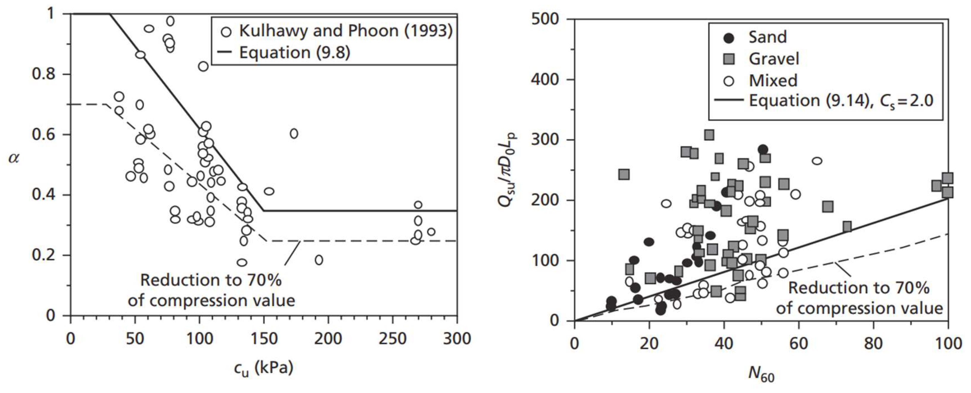
Figure 3.
simplified schematic of the optimisation algorithm.
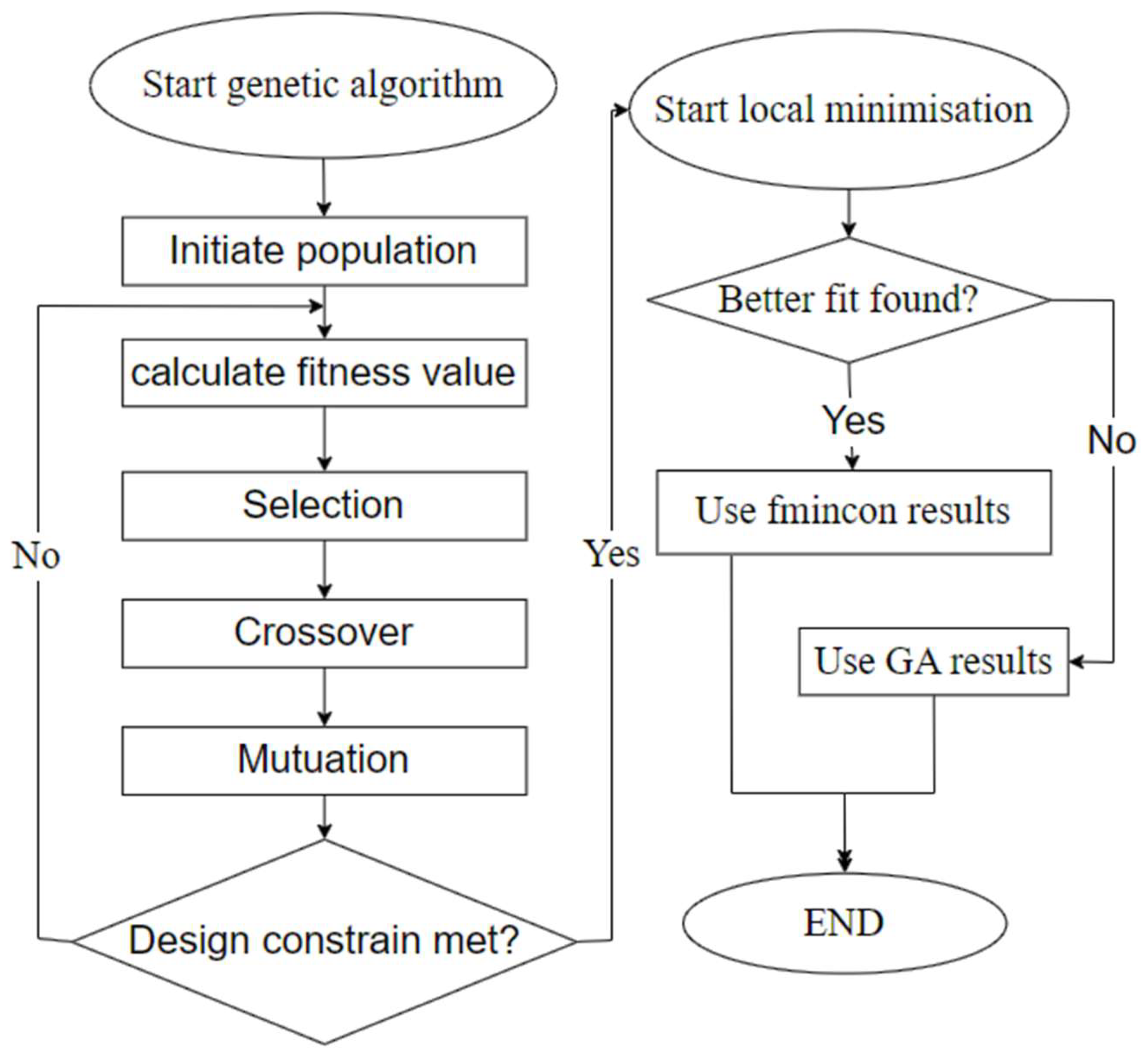
Figure 4.
optimal concrete design parameters for tension piles in undrained clay soil.
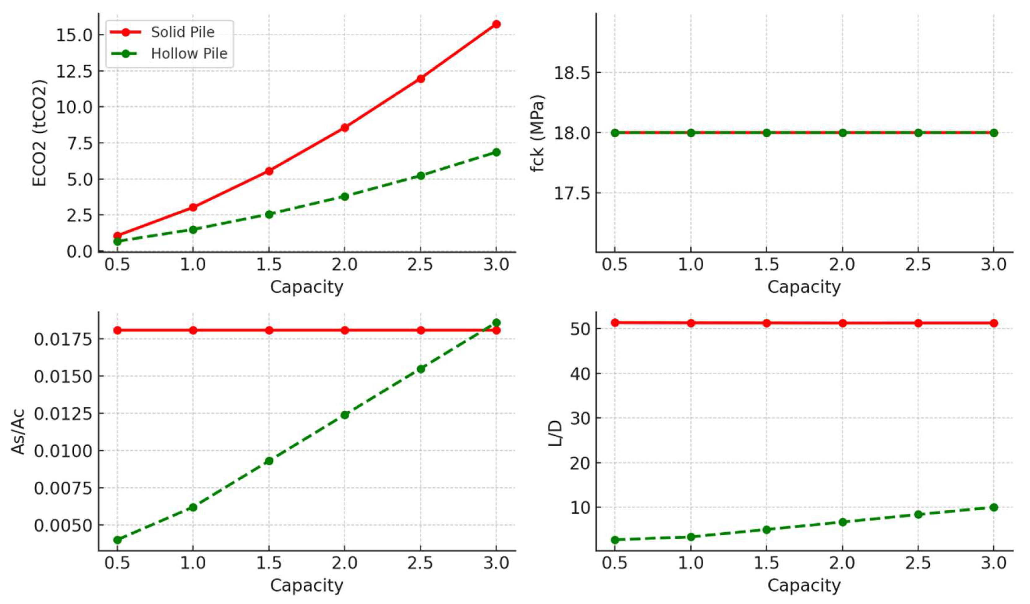
Figure 5.
optimal steel design parameters for tension piles in undrained clay soil.
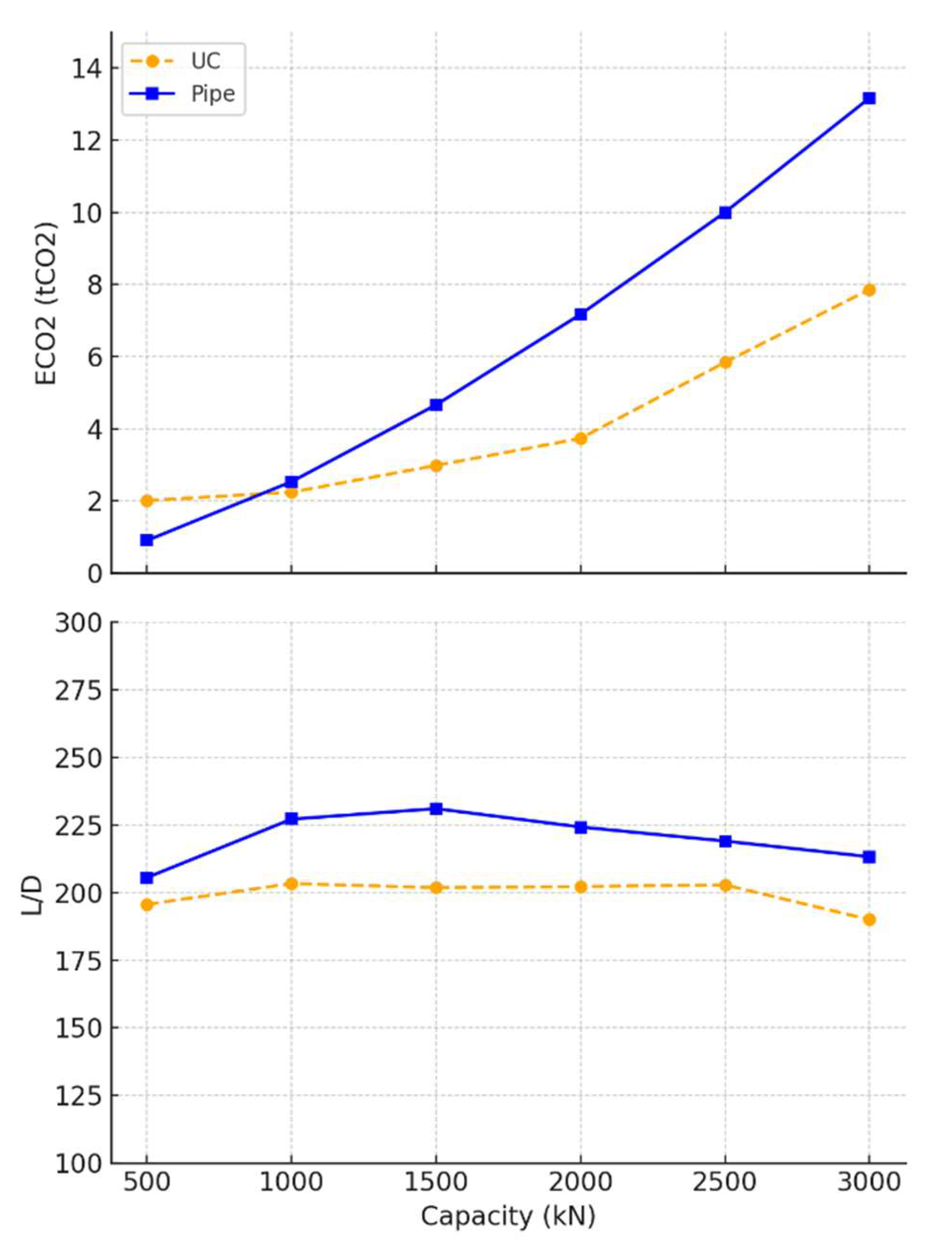
Figure 6.
optimal timber design parameters for tension piles in undrained clay soil.
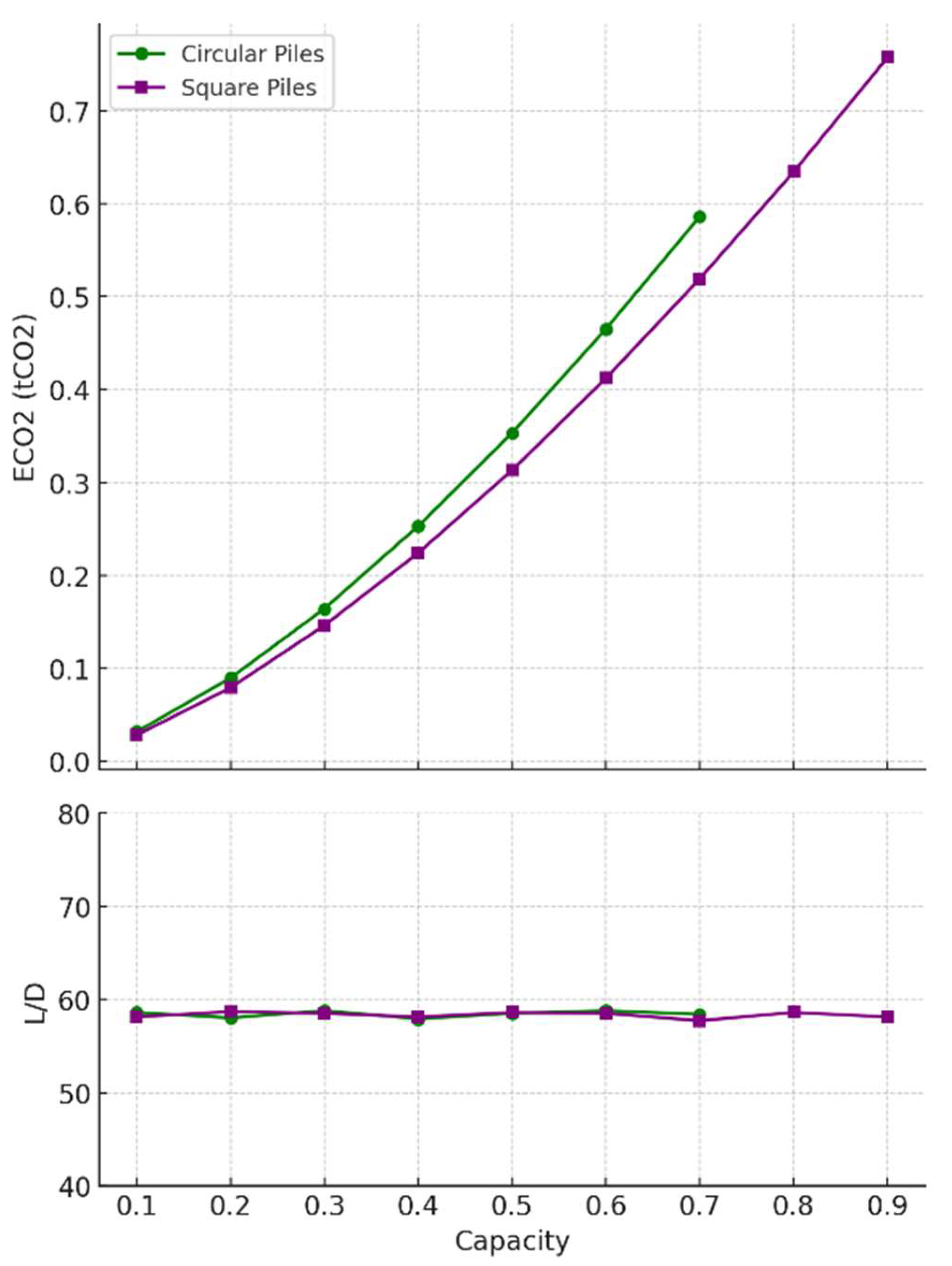
Figure 7.
optimal concrete design parameters for tension piles in loose sand soil.
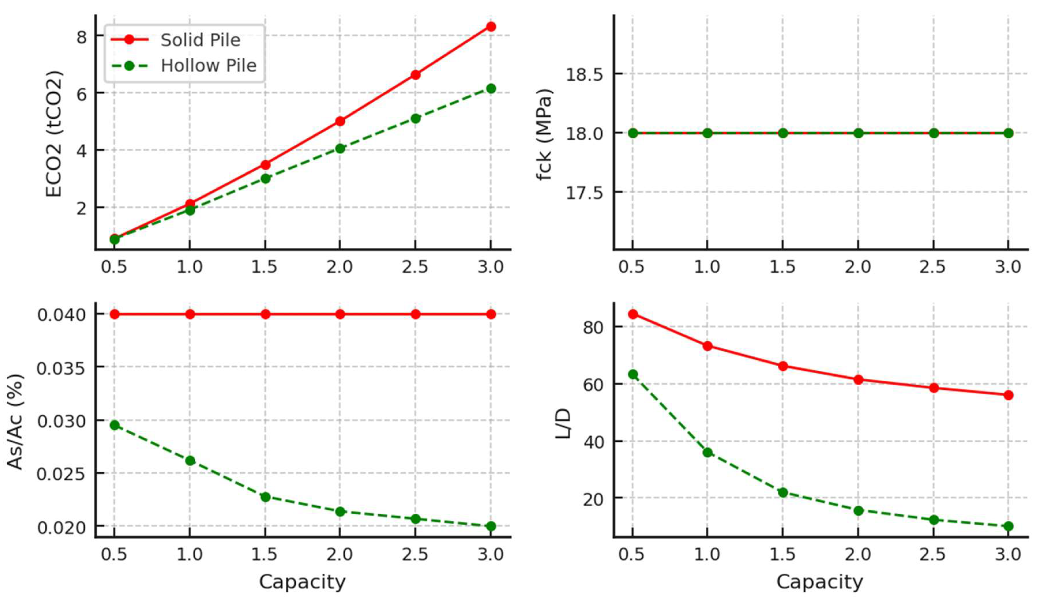
Figure 8.
optimal steel design parameters for tension piles in loose sand soil.
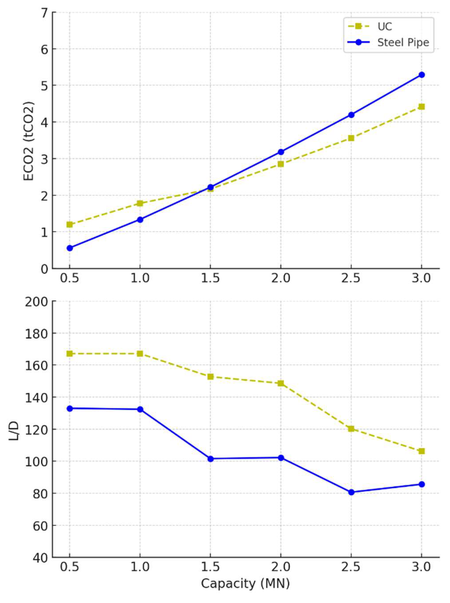
Figure 9.
optimal timber design parameters for tension piles in loose sand soil.
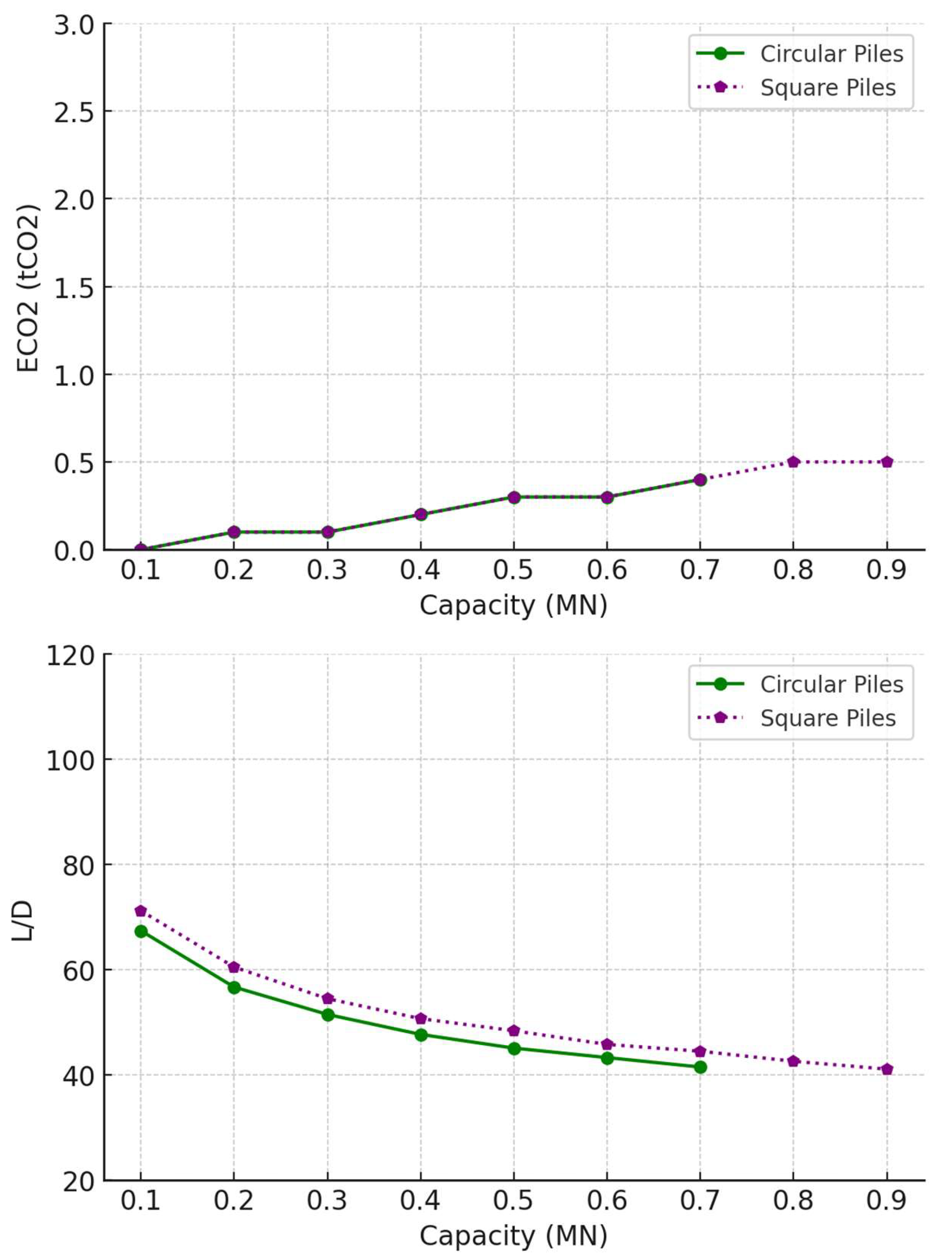
Figure 10.
Embodied carbon values for optimal pile design in undrained clay: left) compression piles (Abushama et al., 2025) – right) tension piles.
Figure 10.
Embodied carbon values for optimal pile design in undrained clay: left) compression piles (Abushama et al., 2025) – right) tension piles.
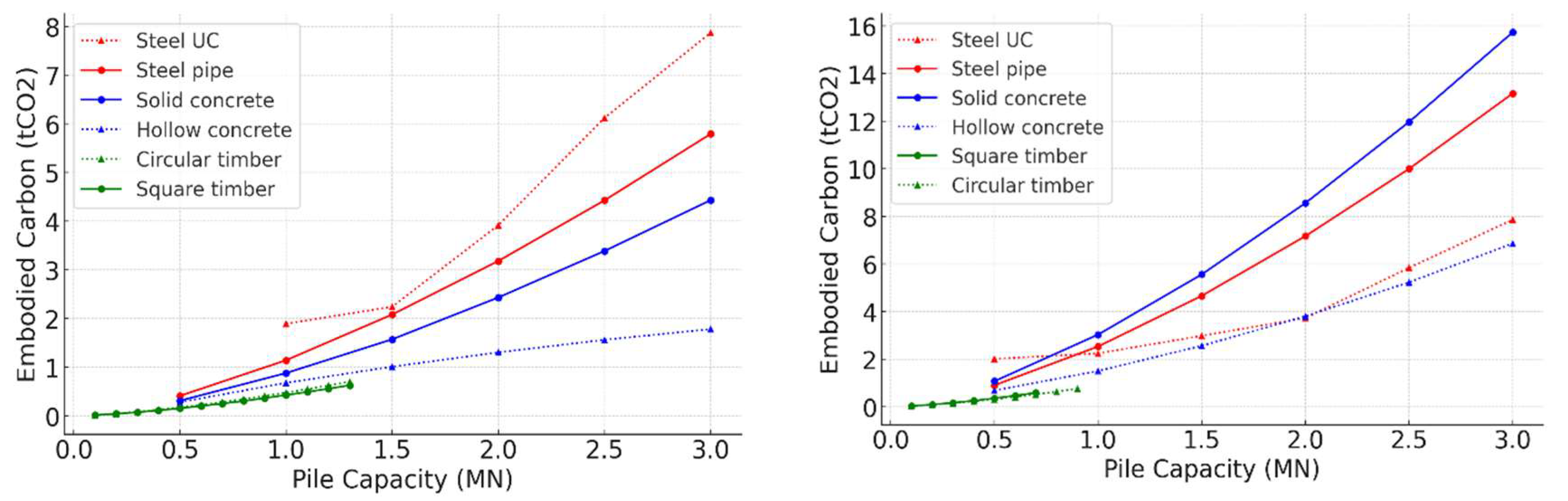
Figure 11.
Embodied carbon values for optimal pile design in loose sand: left) compression piles (Abushama et al., 2025) – right) tension piles.
Figure 11.
Embodied carbon values for optimal pile design in loose sand: left) compression piles (Abushama et al., 2025) – right) tension piles.
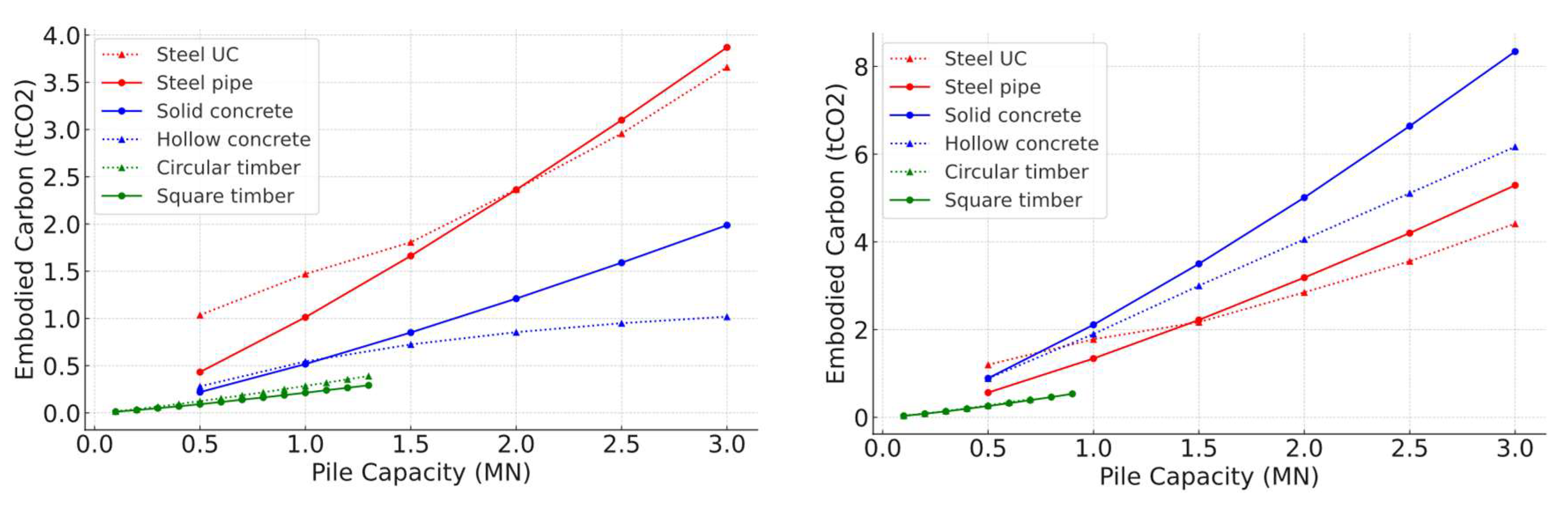
Figure 12.
The studied structure and a schematic of the foundation system.
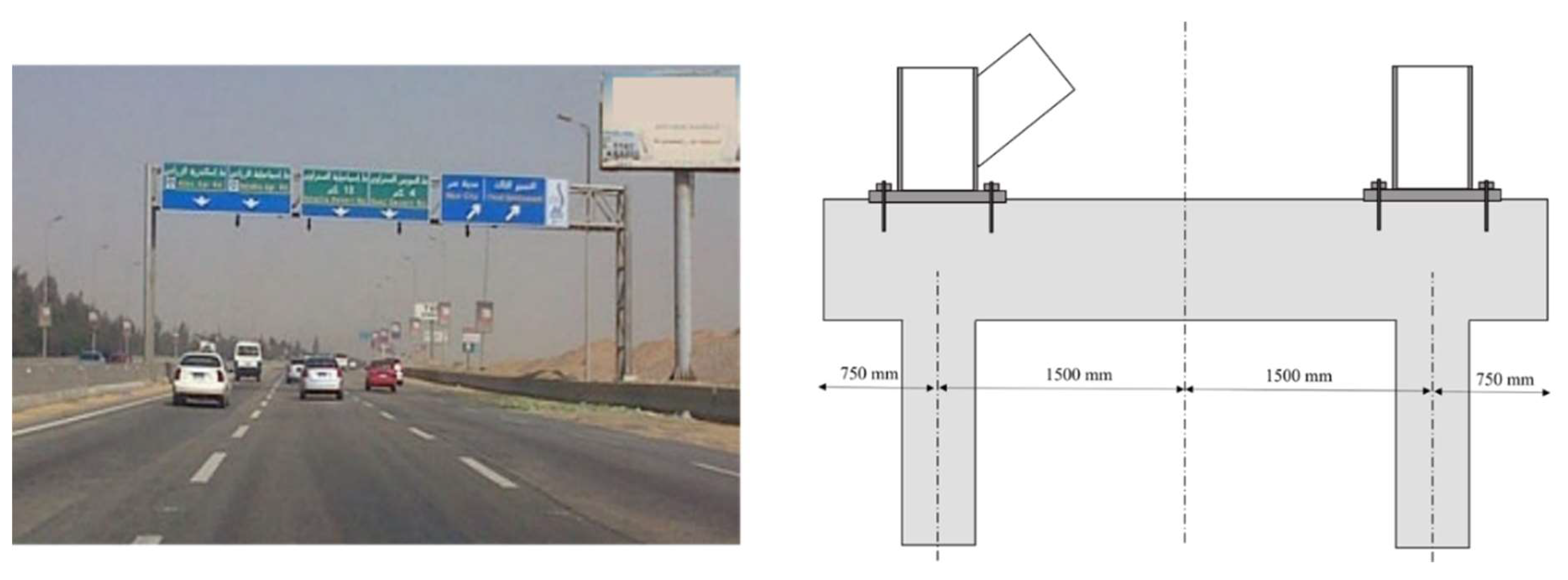
Figure 13.
Embodied carbon ranking for the case study’s optimal pile design alternatives.
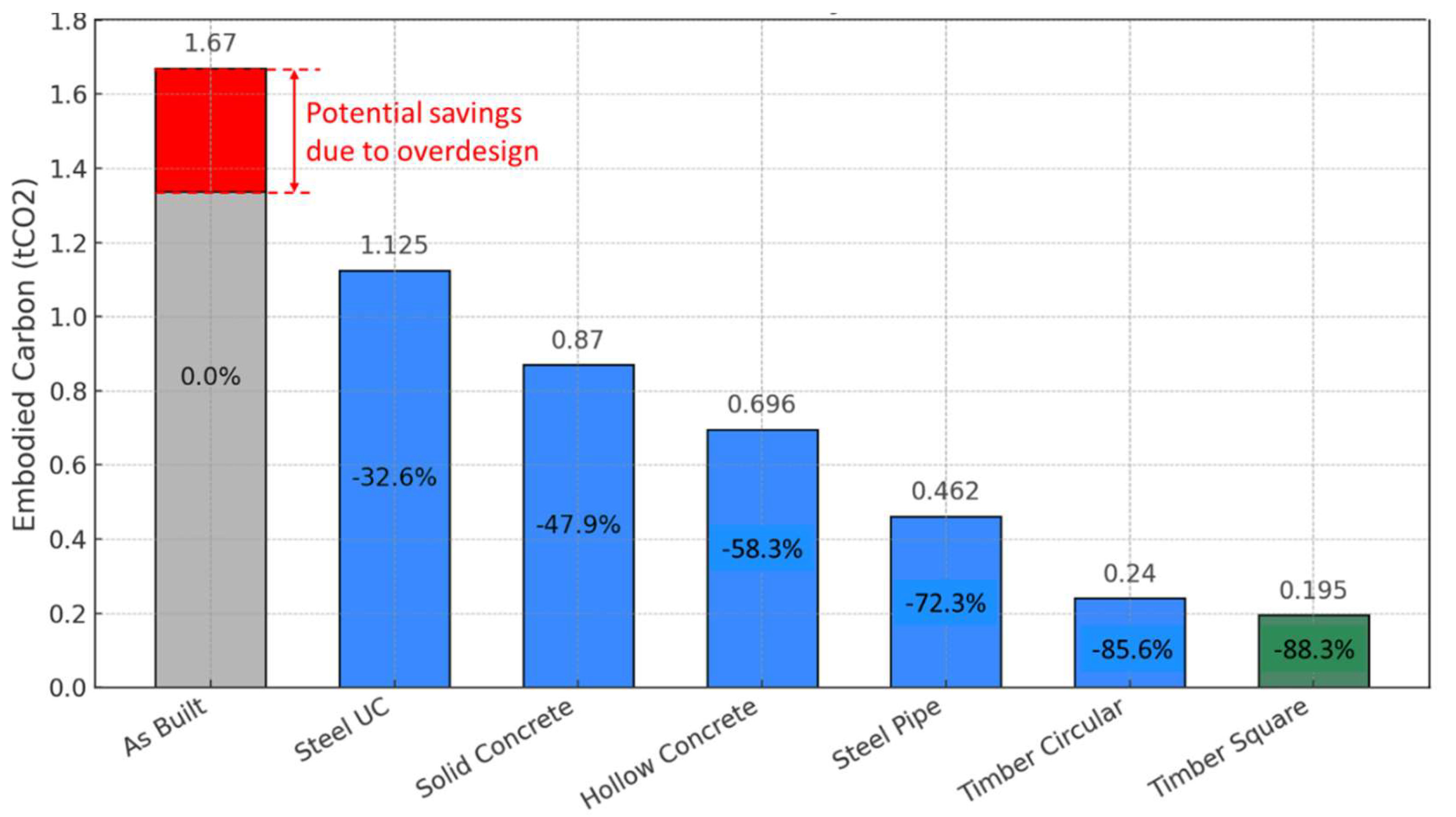
Table 1.
Soil model properties as tested by Knappet and Craig (2012).
| Soil type | Property | Symbol | Value (unit) |
|---|---|---|---|
| Undrained clay | Unit weight | 18 (kN/m3) | |
| Undrained shear strength | cu | 80 + 1.5z* (kPa) | |
| Poisson’s ratio | v | 0.2 | |
| Shear modulus | G | 5000 + 500z* (kPa) | |
| Dry loose sand | Unit weight | 15 (kN/m3) | |
| Angle of internal friction | φ′ | 32o | |
| Pile-soil interface angle | δ′ | 24o | |
| *Depth from the top. | |||
Table 3.
Design parameters for the different tested pile geometries.
 |
Table 2.
Embodied carbon factors across materials and life cycle stages (Gibbons et al., 2022).
| Material | A1-A3 (kgCO2e/kg) |
A4 (kgCO2e/kg) |
A5 (kgCO2e/kg) |
Assumptions |
| In-situ cast concrete | 0.082 + 0.002 fck | 0.005** | 0.053 | Linear regression of the ICE inventory (Abushama et al., 2023b) |
| Reinforcement steel bars | 1.99 | 0.032* | 0.053 | Worldwide steel of low recycled content |
| Construction steel | 1.55 | 0.032* | 0.01 | Worldwide open steel sections |
| Timber | 0.263 | 0.032* | 0.01 | Studwork, softwood |
| * Material considered nationally manufactured with a road travel distance of 300 km. ** Material considered locally manufactured with a road travel distance of 50 km (Gibbons et al., 2022) | ||||
Table 4.
Optimal design parameters for concrete piles at different load capacities.
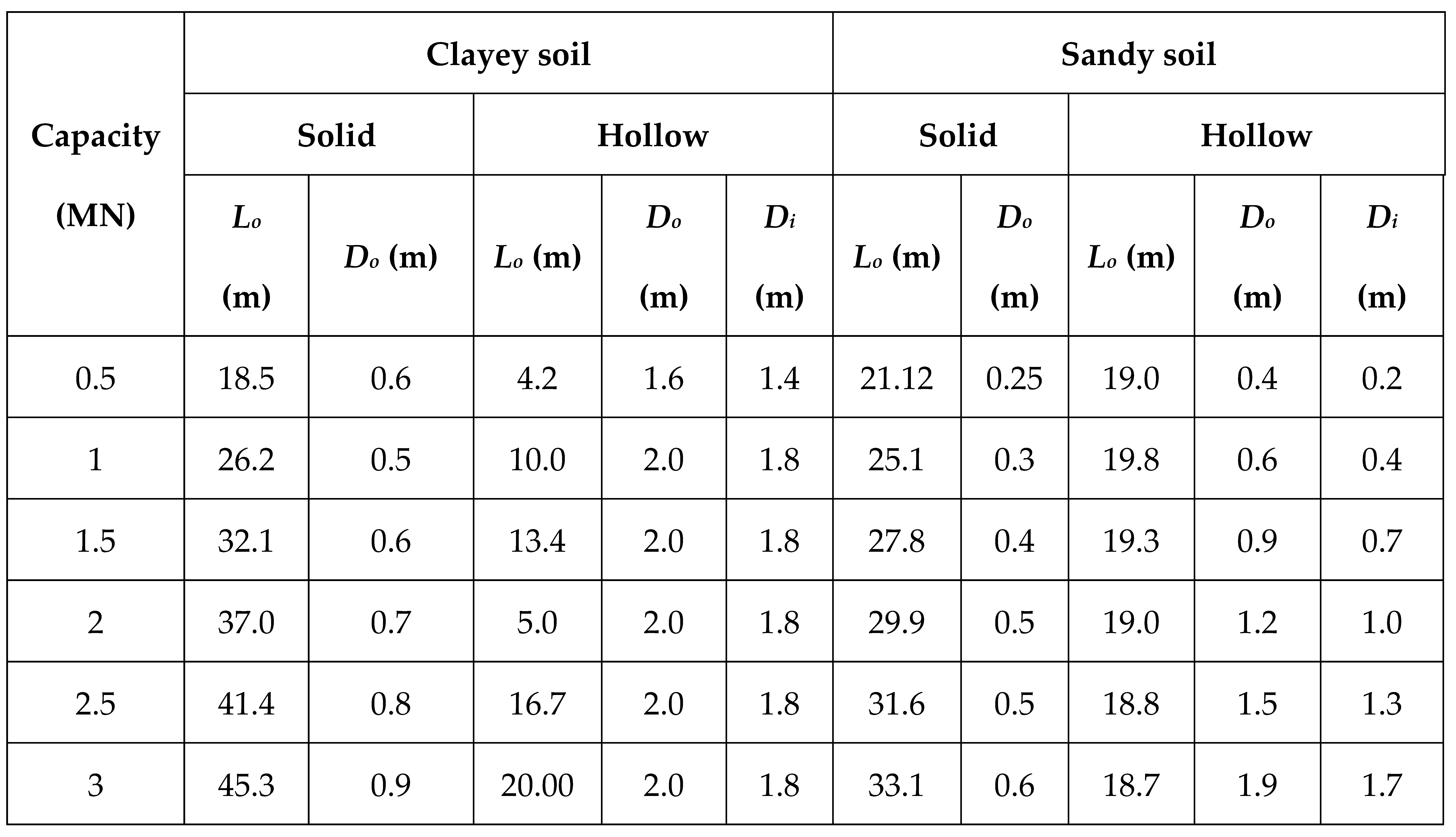 |
Table 5.
Optimal design parameters for steel piles at different load capacities.
| (MN) | Clayey soil | Sandy soil | ||||||||
|---|---|---|---|---|---|---|---|---|---|---|
| Pipe section | UC section | Pipe section | UC section | |||||||
| Lo (m) | Do (m) | to (mm) | Lo (m) | section | Lo (m) | Do (m) | to (mm) | Lo (m) | section | |
| 0.5 | 39.8 | 0.19 | 4.0 | 30.2 | 152x152x37 | 25 | 0.19 | 4.0 | 21.8 | 152x152x23 |
| 1 | 50.3 | 0.22 | 5.0 | 32.0 | 152x152x51 | 29.7 | 0.22 | 5.0 | 25.4 | 152x152x23 |
| 1.5 | 68.9 | 0.32 | 6.0 | 41.0 | 203x203x46 | 32.9 | 0.32 | 6.0 | 31.0 | 203x203x46 |
| 2 | 79.6 | 0.36 | 8.0 | 41.3 | 203x203x52 | 36.4 | 0.36 | 8.0 | 31.7 | 203x203x100 |
| 2.5 | 89.0 | 0.41 | 8.0 | 51.6 | 254x254x73 | 37.4 | 0.46 | 8.0 | 31.9 | 257x254x167 |
| 3 | 97.4 | 0.46 | 8.0 | 58.0 | 305x305x79 | 39.1 | 0.46 | 10 | 32.7 | 305x305x18 |
Table 7.
soil properties for the case study.
| Soil parameter [symbol] (unit) | Layer 1 - Sand | Layer 2 - Silty clay |
| Layer depth [z] (m) | [0-25] | [25-42] |
| Unit Weight [γ] (kN/m3) | 19 | 20 |
| Young’s modulus [E] (MPa) | [25-50] | [25-30] |
| Effective cohesion [c] (kPa) | 0 | [20-30] |
| Effective friction angle [φ] (Degrees) | [32-36] | 20 |
Table 8.
optimisation results for the case study tension pile of capacity of 400kN.
| Pile type | Design | Embodied carbon |
| As-built design |
L = 18 m D = 0.5 m fck = 25 MPa As/Ac = 1.5% |
Reference value |
| Solid concrete |
L = 20m D = 0.25 m fck = 25 MPa As/Ac = 4% |
-47.9% |
| Hollow concrete |
L = 17m Do = 0.3 m, Di = 0.1 fck = 25 MPa As/Ac = 2.4% |
-58.3% |
| Steel pipe |
L = 23.62 D = 0.2 m t = 3 mm |
-72.3% |
| Steel UC |
L = 16 m Section = 203x203x46 |
-32.6% |
| Circular timber |
L = 16.5 D = 0.35 C24 |
-85.6% |
| Square timber |
L = 15.5 D = 0.3 C24 |
-88.3% |
Disclaimer/Publisher’s Note: The statements, opinions and data contained in all publications are solely those of the individual author(s) and contributor(s) and not of MDPI and/or the editor(s). MDPI and/or the editor(s) disclaim responsibility for any injury to people or property resulting from any ideas, methods, instructions or products referred to in the content. |
© 2025 by the authors. Licensee MDPI, Basel, Switzerland. This article is an open access article distributed under the terms and conditions of the Creative Commons Attribution (CC BY) license (http://creativecommons.org/licenses/by/4.0/).
Copyright: This open access article is published under a Creative Commons CC BY 4.0 license, which permit the free download, distribution, and reuse, provided that the author and preprint are cited in any reuse.


