
Submitted:
24 March 2025
Posted:
25 March 2025
You are already at the latest version
Abstract
In this study, a self-propelled hard hose traveler is designed based on the traditional hard hose traveler. The traveler demonstrated enhanced field applicability and intelligence level in Europe and central-eastern China. A parametric configuration scheme was attained through the irrigator’s computational modeling and experimental validation. This study proposed a uniform water distribution calculation model for single-sprinkler linear-move irrigation. The deviation rate between calculated and experimental values was 7.3%. The average application depth decreased with increased sprinkler motion speed and path spacing. The uniformity of water distribution (CU value) exhibited an oscillating trend as the path spacing varied. When moving along a specific path, the CU value increased and decreased with the increased sprinkler rotation angle. By combining irrigation and sprinkler motions, the CU value decreased and increased with the increased sprinkler rotation angle. The combined sprinkler and irrigation motions showed a significantly better effect than the specific path irrigation. The highest CU value was 95.0%, with a nozzle diameter of 16.0×6.0 mm2, a sprinkler rotation angle of 180°, and a path spacing of 1.6 R.
Keywords:
computational model
; sprinkler motion speed
; application depth
; uniformity of water distribution (CU value)
; path spacing
; self-propelled hard hose traveler
1. Introduction
The traditional hard hose traveler is water-saving irrigation equipment. It operates continuously with motion and sprinkling capabilities [1]. It suits for large and medium-sized field plots in Europe and central-eastern China [2,3,4,5]. To enhance the irrigator’s applicability in small field plots [6] and its intelligence [7], this paper proposed a self-propelled hard hose traveler with enhanced mobility. The self-propelled hard hose traveler uses an electric tracked vehicle to carry the sprinkler for slope climbing and directional irrigation. The proposed traveler adjusts the speed through a remote terminal at different levels depending on the application depth, providing a novel approach for water-saving irrigation equipment.
Water application performance is critical for the quality of the irrigator [8]. The application depth and CU value are influential metrics for evaluating the water application performance of traditional hard hose travelers [9]. The application depth depends on the crop water requirement and significantly impacts crop yield [10]. The American Society of Civil Engineers recommends CU value as a key indicator for evaluating the distribution of sprinkler water applications [11]. The Technical Code for Sprinkler Engineering in China defines the CU value as the ratio of the sum of the absolute deviations of the application depth at each measurement point from the average application depth to the total application depth [12,13]. Therefore, the application depth and CU value are crucial for evaluating the sprinkler performance of a self-propelled hard hose traveler with a single sprinkler motion in a straight line.
Currently, research on water application performance mainly focuses on computational models [14,15,16] and experimental outcomes [17,18,19]. Wang et al. [20] proposed a jet-impact rotating sprinkler by combining jet and impact flows. They studied the sprinkler water application performance through experimental methods. Gao et al. [21] used Teejet atomizing nozzles. They explored the influence of equivalent diameter, installation height, and working pressure on the water application performance of atomizing nozzles through experimental analysis and theoretical calculations. Gao et al. [22] investigated the impact of installation height and working pressure on water application performance using atomizing nozzles, employing computational models and experiments.
Numerous studies have shown the relationship between operating conditions and water application performance through computational and experimental methods in the irrigator field. Wu [23] and Bittinger et al. [24] use computational models to simplify the sprinklers’ radial water distribution lines into regular shapes, such as triangles and ellipses, with time as the dependent variable. The CU value can be calculated by integrating this formulation. However, this simplification method for evaluating radial lines lacks accuracy. Smith et al. [25] and Wiggington et al. [26] investigated the CU value of a single traditional hard hose traveler used in the field. They found an average CU value of 62%, indicating poor performance. Therefore, they researched combined irrigation with sprinkler motion using traditional hard hose travelers. Ge et al. [27,28] represented traditional hard hose travelers’ radial water distribution lines using cubic spline interpolation, Lagrange interpolation, and polynomial fitting. They analyzed multiple rotation angles and path spacings using computational models. They found that the optimal sprinkler rotation angle is 240°–320°, the combination spacings are 1.5–1.7 R, and the CU value is greater than 85%. Ge et al. measured the fixed-spray radial water distribution lines. They observed that the selected nodes were relatively sparse. Hills et al. [29] used computations and experimentation and found that when a linear-move sprinkler system moves at 10–100% of its maximum speed, the CU value ranges from 92–96%. When the CU value decreases slightly, there is a good correlation between average application depth and motion speed. Li et al. [30] observed that the CU value of a center-pivot sprinkler system slightly decreased with the increased speed. The published studies on computational and experimental methods showed that sprinkler rotation angle, path spacing, and sprinkler motion speed significantly impact the irrigator’s average application depth and CU value.
This study used cubic spline interpolation curves to determine the CU value for single-sprinkler linear-move irrigation, considering several water applications of the motion sprinkler and the radial application depth per revolution. This study investigated the sprinkler’s water application performance when it moves along a specific path and combines irrigation with sprinkler motion. The study investigated nozzle diameter, motion speed, and sprinkler rotation angle as design variables.
2. Structure and Operating Principle of the Self-Propelled Hard Hose Traveler
The self-propelled hard hose traveler is operated by a remote terminal. It primarily comprises the reel cart, polyethylene tube, electric-tracked vehicle, impact sprinkler, and an integrated motor-gearbox system, as shown in Figure 1. The electric-tracked vehicle employs a crawler structure with sprinkler heads. Figure 2 shows a prototype of the self-propelled hard hose traveler.
The reel truck allows the polyethylene tube to unfold, store, and retract. The electric tracked vehicle is characterized by its maneuverability and flexible walking. The vehicle loads impact sprinklers, changing the irrigation position, unfolding the polyethylene tube, and guiding. The motor-gearbox system provides power to retract the polyethylene tub. During sprinkling irrigation, the reel truck is stored at the water source. The electric-tracked vehicle moves away from the hose reel cart, pulls out the polyethylene tube, and performs mobile sprinkling irrigation. The polyethylene tube disintegrates from the electric-tracked vehicle at the end of the sprinkling irrigation operation. The motor-gearbox system drives the reel to rotate and retract the polyethylene tube. Then, the electric-tracked vehicle is transferred to the next sprinkling point.
3. Uniformity Model for Single-Sprinkler Linear-Move Irrigation
3.1. Radial Water Distribution Curve
Figure 3 shows the radial water distribution curve for the 40PY2 impact sprinkler in the laboratory, with a 19.7 m3 h⁻1 flow rate. By following GB/T 22999-2008[31] standard, the nozzles were selected for the impact sprinkler with diameters of 16.0×6.0 mm and 15.0×6.0 mm. The cubic spline curves are used to calculate interpolation for the radial water distribution of sprinklers [32]. The water distribution curve is developed using Eq (1). In the laboratory tests, Eq (2) is used to calculate the number of irrigation cycles for the sprinkler. The sprinkler rotates at an angle of 180º, with a total irrigation time of 0.5 hours. The rotation period T is recorded for the sprinkler to complete a 180º rotation. Drawing on the verification methods for radial water distribution curves [33,34], the deviation between the experimental and calculated values of the average irrigation intensity (set as the quotient of the flow rate and the irrigation area) is within 4%.
where d is the distance from the sprinkler to the measuring point in m; ρ(d) is the application rate based on the distance between the sprinkler and the measuring point in mm/h; Ai, Bi, Ci, and Di are the coefficients of Eq. (1); di is polynomial nodes with integer values in m.
3.2. Superposition of Transferred Water Volume
The superimposed value of transferred water volume is calculated by considering the number of watering passes during the sprinkler's movement. The radial application depth per revolution determines the total application depth at each measurement point. Figure 4 shows the mobile irrigation process of the self-propelled hard hose traveler and the water reception status at measurement point M. Figure 4a shows the sprinkler's spray rotation direction (solid line) and return direction (dashed line). Figure 4b shows the water reception at measurement point M and the sprinkler's radial movement. Figure 4c shows the relationship between the position of measurement point M, the position of the sprinkler, and the sprinkler's rotation angle (where 180° ≤ β < 360°). Mstart and Mend are the starting and ending positions of water reception at point M, respectively, with a distance of L (m) between them. β (°) shows the rotation angle of the motion sprinkler.
Motion sprinkler irrigation involves two dynamic processes: the sprinkler motion uniformly along a path and rotating periodically. During the calculation, these two dynamic processes are considered independently. Based on the sprinkler's rotation cycle, the distance traveled by the sprinkler is divided into multiple units. The distance between the sprinkler and measurement point M is calculated for each unit position of the sprinkler. This distance, combined with Eqs. (1) and (2), allows for determining the application depth within a particular cycle. Upon completion of the sprinkler's movement, the total application depth at point M gives the superimposed value of the application depth at each unit position.
This study used three assumptions.
1) The sprinkler jet morphology and the water distribution in the range of water application remain constant during each rotation.
2) The change in distance between the measured point and the sprinkler is negligible during each rotation.
3) Wind speed, direction, temperature, and humidity do not affect water distribution under natural conditions.
The process of superimposed water application at point M consists of five steps:
Step 1: The distance l (m) from the sprinkler to the point where the projection of M onto the path intersects is calculated according to Eq. (3).
where xm is the distance from measurement point M to the motion path, in m.
Step 2. The period t(h) of the rotating angle β of the motion sprinkler and the radial motion distance Δl (m) within one complete cycle are established. These are expressed in Eqs. (4) and (5).
Step 3: Determine the sprinkler motion length L (m). Assuming that the measurement point M moves radially, and the sprinkler sprays water in a fan shape at an angle β, then point M receives water within the fan-shaped area. Therefore, within the boundary of the fan shape, the length of the line passing through point M and parallel to the movement path is the sprinkler's motion length L. This is shown in Figure 4c and expressed as Eq. (6).
Step 4. The real-time positions of the sprinkler and measurement point M are determined. Length L is divided into n distance units (Eq. (7)). After labeling the distance units Δl with j ∈ (0, n), the distance ΔL from the sprinkler starting at point Mstart to the jth unit is obtained, as expressed in Eq. (8). Distance dj (m) from the sprinkler to point M within the jth distance unit is given by Eq. (9):
Step 5. The depth of application h(dj) (mm) at point M during one complete rotation cycle of the sprinkler and the cumulative depth of application hn (mm) after n rotation cycles are calculated using Eqs. (10) and (11), respectively.
3.3. Average Application Depth and Uniformity of Water Distribution
Chinese national standards [35,36] typically employ a radial or grid layout for arranging measurement points with the application depth for a specific area. The average application depth and water distribution uniformity [37,38,39] are calculated considering the application depth from multiple measurement points. This is expressed in Eqs. (12) and (13).
where h is the average application depth for motion sprinkler irrigation in mm; CU is the % uniformity of water distribution.
4. Experimental Validation of the Average Application Depth
This study used grid layout measurement points for experiments, with water buckets arranged in a 1.5×1.5 m2 formation, as shown in Figure 5. The experiment was conducted at the Lizhong Agricultural Machinery Cooperative in Huantai County, Zibo, China. The experiment used an electric tracked vehicle with sprinklers to achieve a moving speed of 15 m h−1. After the sprinkler irrigation experiment, the columns’ radial lines were averaged. This average was taken as the experimental value. Experimental parameters considered the reel cart model JP50-180, 40PY2 impact sprinkler, nozzle diameter of 16.0×6.0 mm2, 19.7 m3 h−1 flow rate, the sprinkler rotation angle of 240°, the sprinkler installation height of 1.3 m, the plastic bucket diameter of 200 mm, and the plastic bucket height of 170 mm. Environmental parameters were characterized by gusty winds with a speed range of 1.23–2.55 m s−1, maintaining an air temperature of 12.3 °C and an air relative humidity of 24.82%. Figure 5 shows the comparison of the experimental and the calculated values.
Figure 6 shows the calculated and experimental application depth curves for motion sprinkler irrigation, with an average application depth of 23.3 mm and 25.3 mm, respectively. The deviation rate is 8.6%, indicating that the calculated values of application depth are mostly accurate. When comparing the two curves, the experimental values are higher than the calculated values. The smallest deviation on the curve occurred at the 12 m point, with a deviation rate of 2.7%. The maximum deviation occurred at 28.5 m, with a deviation rate of 70.0%. The wind speed and direction influence significant deviations at points on the two curves. Overall, the accuracy of the experimental values is controllable.
5. Irrigation Performance of Single-Sprinkler Linear-Moving Irrigation
5.1. Move Along a Specific Path
5.1.1. Different Nozzle Diameters
Table 1 and Figure 7 give details of the application depth and CU values for various nozzles with a sprinkler rotation angle of 240° and a motion speed of 15 m h−1. The average application depth is around 23.0 mm, and the CU values for the two nozzles are 74.9% and 80.0%, respectively. The optimal nozzle diameter for the 40PY2 impact sprinkler in terms of CU value is 16.0×6.0 mm2.
5.1.2. Different Sprinkler Motion Speeds
The application depth and CU values are given in Figure 8 and Table 2 when the sprinkler rotation angle is 240° and the nozzle diameter is 16.0 × 6.0 mm. With the increased motion speed, the average application depth decreases in a power function form. Eq (14) explains this with a fitting coefficient of 1. The CU value exhibits slight oscillatory changes with an increasing motion speed of around 80%. The fluctuation range of the CU value at 0.3% is insignificant and does not demonstrate the impact of motion speed on water distribution. Furthermore, fluctuations in CU values are caused by variations in the length of ∆l. Therefore, the influence of sprinkler motion speed on CU values can be neglected.
5.1.3. Different Sprinkler Rotation Angles
Figure 9 and Table 3 give the application depth and CU values at 15 m/h and 16.0×6.0 mm2 the nozzle diameter. The average application depth remains constant at around 21.3–21.5 mm, whereas the CU value varies from 68.7–80.0%. The relative deviation in the average application depth is due to discrepancies in value selection and model calculations.
Figure 9 shows a downward trend when the sprinkler rotation angle increases, the initial value of the application depth curve. The curve showed a normal distribution, with a peak value around 13.5m, indicating an upward trend. However, the average application depth remained unchanged. The CU value increased and decreased. The sprinkler irrigation effect of the 40PY2 impact sprinkler was optimal when the rotation angle was within 210–270°, with the best CU value being greater than or equal to 80.0%.
5.2. Combined Irrigation with Sprinkler Motion
The study showed that a specific path movement of the self-propelled hard hose traveler does not follow the Technical Code for Sprinkler Engineering [12] (CU value of 85%). Consequently, this study used a lower value for the combined sprinkler movement for irrigation. At a path spacing of 2.0 R, the sprinkling effect is identical when not combined.
5.2.1. Different Nozzle Diameters
When the sprinkler rotation angle is 240°, and the motion speed is 15 m h−1, the average application depth and CU values for different nozzles at path spacings of 1.0–1.9 R are given in Table 4. At the same path spacing, there are deviations in the average application depth and CU values at different nozzles. As the path spacing increases, the average application depth decreases constantly for the same nozzle, while the CU value demonstrates a wavy trend. It is difficult to investigate the influence of nozzle diameter on the average application depth, but the optimal CU values are above 90%. The highest CU value of 92.0% is achieved with a nozzle diameter of 16.0×6.0 mm2 at a path spacing of 1.8 R. The technical code for Sprinkler Engineering for the selected path spacings of the 40PY2 impact sprinkler is 1.6–1.9 R.
5.2.2. Different Sprinkler Motion Speeds
Table 5 gives the application depth and CU values for a sprinkler rotation angle of 240° and a nozzle diameter of 16.0×6.0 mm2. At the same path spacing, the average application depth decreases constantly with an increased motion speed while the CU value remains unchanged. At the same motion speed, the average application depth decreases continuously as the path spacing increases, and the CU value demonstrates an oscillatory trend. The CU values for the 40PY2 impact sprinkler fluctuate at 64.4–92.1%, and the highest CU value is 92.0 at a path spacing of 1.8 R. The technical code for Sprinkler Engineering for the selected path spacings for the 40PY2 impact sprinkler is 1.7–1.9 R.
5.2.3. Different Sprinkler Rotation Angle
Table 6 details the average application depth and CU values for a nozzle diameter of 16.0×6.0 mm2 and a motion speed of 15 m h⁻1. At the same sprinkler rotation angle, the average application depth gradually decreases with increased path spacing, while the CU value exhibits a wavy trend. For the same path spacing, as the sprinkler rotation angle increases, the average application depth fluctuates within ±1 mm, and the CU value exhibits a decreasing and increasing trend, fluctuating 60.1–95.0%. The highest CU value occurs at 95.0% when the sprinkler rotation angle is 180°, and the path spacing is 1.6 R. The technical code for Sprinkler Engineering for the selected path spacing of the 40PY2 impact sprinkler is 1.6–1.9R, and the selectable sprinkler rotation angles are 180°, 210°, and 240°.
6. Results and Discussion
When the sprinkler moves along a specific path performing irrigation with sprinkler motion, the optimal CU values are approximately 75–90%. The sprinkling effect of the sprinkler moving along a specific path is shown in Figure 10, with a nozzle diameter of 16.0×6.0 mm2, a moving speed of 15 m h−1, and a sprinkler rotation angle of 180°. Figure 11 shows the effect of combined irrigation with sprinkler motion with a path spacing of 1.6 R. Figure 11 shows that the application depth uniformity is better than that in Figure 10. Combined irrigation with sprinkler motion suits conventional sprinkling operations, while motion along a specific path is used for irrigation in irregular areas. This study indicates that the nozzle diameter and sprinkler motion speed have insignificant effects on the CU value, with the sprinkler rotation angle optimal range being 180°–240°. From the technical code for Sprinkler Engineering, the highest CU value is approximately 95%, with a nozzle diameter of 16.0×6.0 mm2, a sprinkler rotation angle of 180°, and a path spacing of 1.6 R. Table 7 summarizes the hydraulic parameters of the self-propelled hard hose traveler (CU ≥ 85%), showing key guidance for farmers in operating this sprinkler.
7. Conclusions
This study investigated the hydraulic performance of a self-propelled hard hose traveler with a single-sprinkler arrangement (40PY2 impact sprinkler). The impact of nozzle diameter, sprinkler motion speed, sprinkler rotation angle, path spacing on average application depth, and the CU value are investigated through numerical modeling and experimentation. The study derived parameter configuration schemes that guide the field operations. The specific conclusions of this study are as follows:
(1) A uniformity model for single-sprinkler linear-move irrigation has been established. The deviation rate between calculated and experimental values was 7.3% in experimental validation.
(2) The CU value is affected by nozzle diameter and motion speed, exhibiting an oscillating trend with changes in path spacing. When moving along a specific path, the CU value increases and decreases as the sprinkler rotation angle increases. When irrigation and sprinkler motion are combined, the CU value decreases and increases with increased sprinkler rotation angle. The average application depth decreases with increased sprinkler motion speed and path spacing and remains unaffected by the sprinkler rotation angle. Defining the variation in average application depth with nozzle diameter is challenging.
(3) The effect of combined irrigation with sprinkler motion is significantly better than that of moving along a specific path, with optimal CU values around 90% and 75%. The study provided parametric configurations for self-propelled hard hose travelers using combined irrigation with sprinkler motion. The highest CU value is 95.0%, with a parameter configuration of a nozzle diameter of 16.0×6.0 mm2, a sprinkler rotation angle of 180°, and a path spacing of 1.6 R.
The irrigation performance of self-propelled hard hose travelers has been studied thoroughly. Future research will focus on path planning for cooperative irrigation among multiple sprinkler irrigators to achieve comprehensive irrigation (CU ≥ 85%) across complex and diverse field layouts and reduce operational and management costs.
Funding
This research was supported by the following grants: the Natural Science Foundation of the Jiangsu Higher Education Institutions of China (24KJB210020); the Key Laboratory of Fluid and Power Machinery (Xihua University), Ministry of Education (LTDL-2024015); Suzhou Vocational University (KY202304003, 202305000003).
Data Availability Statement
Data will be available upon request from corresponding authors.
Conflicts of Interest
Author Zhengdian Xu was employed by Suzhou Vocational University. The remaining authors declare that the research was conducted in the absence of any commercial or financial relationships that could be construed as a potential conflict of interest.
References
- Polat, T.; Çolak, A. Development of Fertigation System for Hose Reel Irrigation Machines. In 15th International Congress on Agricultural Mechanization and Energy in Agriculture; Springer: Cham, Switzerland, 2024; pp. 175–185. [Google Scholar]
- Polat, T.; Çolak, A. The Use of Hose Reel Irrigation Machines and Energy Efficient Components in Irrigation. Soil Studies 2024, 13, 55–63. [Google Scholar] [CrossRef]
- Lin, X.J.; Yan, H.J.; Hui, X.; Qiu, Z.P. Irrigation/fertilization model and comprehensive evaluation system for a hose-reel sprinkler. Transactions of the CSAE (in Chinese with English abstract). 2022, 38, 53–59. [Google Scholar] [CrossRef]
- Zhu, X.Y.; Zhao, Y.; Yuan, S.Q.; Liu, J.P.; Tang, L.D. Current situation and development considerations of mechanized irrigation in hilly and mountainous areas. JDIME 2024, 42, 294–303. [Google Scholar]
- Chauhdary, J.N.; Li, H.; Jiang, Y.; Pan, X.W.; Hussain, Z.; Javaid, M.; Rizwan, M. Advances in Sprinkler Irrigation: A Review in the Context of Precision Irrigation for Crop Production. Agronomy 2023, 14, 47. [Google Scholar] [CrossRef]
- Tang, L.D.; Yuan, S.Q.; Liu, J.P.; Qiu, Z.P.; Ma, J.; Sun, X.Y.; Zhou, C.G.; Gao, Z.J. Challenges and opportunities for development of sprinkler irrigation machine in China. JDIME 2022, 40, 1072–1080. [Google Scholar]
- Liu, J.P.; Zhu, X.Y.; Yuan, S.Q.; Li, H.; Tang, Y. Research and development trend of agricultural water-saving sprinkler and micro-irrigation equipment in China. JDIME 2022, 40, 87–96. [Google Scholar]
- Ge, M.S. Study on irrigation quality and optimal design of solar driven hard hose traveler. Doctor Dissertation, Northwest A & F University, Yangling, China, 2018. [Google Scholar]
- Du, L. Analysis of the Characteristics of Xingyu hard hose traveler. China Rural Water and Hydropower 2000, 2000, 57–58. [Google Scholar] [CrossRef]
- Ali, M.H. Fundamentals of Irrigation and On-farm Water Management; Springer Science & Business Media: Berlin, Germany, 2010. [Google Scholar]
- Burt, C.M.; Clemmens, A.J.; Strelkoff, T.S.; Solomon, K.H.; Bliesner, R.D.; Hardy, L.A.; Howell, T.A.; Eisenhauer, D.E. Irrigation performance measures: Efficiency and uniformity. Journal of Irrigation and Drainage Engineering 1997, 123, 423–442. [Google Scholar] [CrossRef]
- GB/T 50085-2007; Techinical Code for Sprinkler Engineering. China Planning Press: Beijing, China, 2007.
- Baum, M.C.; Dukes, M.D.; Miller, G.L. Analysis of residential irrigation distribution uniformity. Journal of Irrigation and Drainage Engineering 2005, 131, 336–341. [Google Scholar] [CrossRef]
- Yang, F.; Jiang, Y.; Li, H.; Hui, X.; Xing, S.C. Accurate model development for predicting sprinkler water distribution on undulating and mountainous terrain. Computers and Electronics in Agriculture 2024, 224, 109196. [Google Scholar] [CrossRef]
- Bautista-Capetillo, C.; Robles Rovelo, C.O.; González-Trinidad, J.; Pineda-Martínez, H.; Júnez-Ferreira, H.E.; García-Bandala, M. Teaching Sprinkler Irrigation Engineering by a Spreadsheet Tool. Water 2023, 15, 1685. [Google Scholar] [CrossRef]
- Li, B.H.; Liu, K.N.; Cai, Y.H.; Sun, W.; Feng, Q. Forecasting and Comparative Application of PV System Electricity Generation for Sprinkler Irrigation Machines Based on Multiple Models. Agronomy 2024, 14, 2696. [Google Scholar] [CrossRef]
- Morcillo, M.; Ortega, J.F.; Ballesteros, R.; Castilllo del, A.; Moreno, M.A. A holistic simulation model of solid-set sprinkler irrigation systems for precision irrigation. Precision Agriculture 2024, 25, 3109–3138. [Google Scholar] [CrossRef]
- Chauhdary, J.N.; Li, H.; Jiang, Y.; Pan, X.W.; Hussain, Z.; Javaid, M.; Rizwan, M. Advances in Sprinkler Irrigation: A Review in the Context of Precision Irrigation for Crop Production. Agronomy 2023, 14, 47. [Google Scholar] [CrossRef]
- Hamid Ahmadi, S.; Solgi, S.; Mashouqi, S. Sprinkler Irrigation System Performance in Winter Wheat Fields: A Comprehensive Study. Journal of Irrigation and Drainage Engineering 2024, 150, 04024001. [Google Scholar] [CrossRef]
- Wang, Z.X.; Jiang, Y.; Pan, X.W.; Wang, L.S. Design and hydraulic performance test of a jet-impingement sprinkler at low pressure. Transactions of the CSAE (in Chinese with English abstract). 2024, 40, 220–227. [Google Scholar] [CrossRef]
- Gao, F.; Zhang, R.; Zhu, D.L.; Zhen, C.J.; Liu, Y.C.; Zhang, X.M.; Zhao, H. Hydraulic performance tests and optimized working parameters of Teejet atomizing nozzles. Transactions of the CSAE 2022, 38, 280–286. [Google Scholar] [CrossRef]
- Gao, F.; Zhu, D.L.; Yan, J.X.; Li, P.Z.; Zhao, L.X.; Xing, X.; Yang, M.F.; Zheng, C.J.; Liu, Y.C.; Zhang, X.M.; Zhang, R. Impact of Mounting Height and Working Water Pressure on the Performance of Micro-sprinkler Irrigation System for Seedling Beds. Journal of Irrigation and Drainage 2022, 41, 119–125. [Google Scholar]
- Wu, D.F. The design and calculation of resultant uniformity of continuously moving mechanical sprinkler systems. Journal of North China Institute of Water Conservancy and Hydroelectric Power 1984, 6, 40–52. [Google Scholar]
- [24]Bittinger, M.W.; Longenbaugh, R.A. Theoretical distribution of water from a moving irrigation sprinkler. Transactions of the ASAE 1962, 5, 26–30. [Google Scholar]
- Smith, R.; Baillie, C.; Gordon, G. Performance of travelling gun irrigation machines. In Proceedings of the Conference of the Australian Society of Sugar Cane Technologists, Cairns, Australia; 2002; p. 235. [Google Scholar]
- Wigginton, D.W.; Raine, S.R. Irrigation water use efficiency in the mary river catchment: On-farm performance evaluations in the dairy sector; National Centre for Engineering in Agriculture Publication: Toowoomba, Australia, 2001; pp. 17–26. [Google Scholar]
- Ge, M.S.; Wu, P.T.; Zhu, D.L. Application of different curve interpolation and fitting methods in water distribution calculation of mobile sprinkler machine. Biosystems Engineering 2018, 174, 316–328. [Google Scholar] [CrossRef]
- Ge, M.S.; Wu, P.T.; Zhu, D.L. Construction and application of mobile spraying uniformity model of hard hose traveler. Transactions of the CSAE 2016, 32, 130–137, (In Chinese with English abstract). [Google Scholar]
- Hills, D.J.; Gu, Y.P.; Rumsey, J.W. Lateral move water application uniformity relative to machine speed. Transactions of the ASAE 1988, 31, 0527–0530. [Google Scholar] [CrossRef]
- Li, Y.C.; Hui, X.; Yan, H.J. Effects of travel speed and collector on evaluation of the water application uniformity of a center pivot irrigation system. Water 2020, 12, 1916. [Google Scholar] [CrossRef]
- GB/T 22999-2008; Rotating sprinkler. SPC: Beijing, China, 2009.
- Smith, R.J.; Gillies, M.H.; Newell, G. A decision support model for travelling gun irrigation machines. Biosystems Engineering 2008, 100, 126–136. [Google Scholar] [CrossRef]
- Seginer, I.; Kantz, D.; Nir, D.; Bernuth, R.D. Indoor measurement of single-radius sprinkler patterns. Transactions of the ASAE 1992, 35, 523–533. [Google Scholar] [CrossRef]
- Molle, B.; Gat, Y.L. Model of water application under pivot sprinkler. II: Calibration and results. Journal of Irrigation & Drainage Engineering 2000, 126, 348–354. [Google Scholar]
- GB/T 21400.1-2008; Traveler irrigation machines---Part 1: Operational characteristics and laboratory and field test methods. SPC: Beijing, China, 2008.
- GB/T 27612.3-2011; Agricultural irrigation equipment-Sprinklers-Part3: CharacterizatiOn of distribution and test methods. SPC: Beijing, China, 2011.
- Fukui, Y.; Nakanishi, K.; Okamura, S. Computer evaluation of sprinkler irrigation uniformity. Irrigation Science 1980, 2, 23–32. [Google Scholar] [CrossRef]
- Vories, E.D.; Asce, S.M.; Von Bernuth, R.D.; Mickelson, R.H. Simulating sprinkler performance in wind. Journal of irrigation and drainage engineering 1987, 113, 119–130. [Google Scholar] [CrossRef]
- Dukes, M. Effect of wind speed and pressure on linear move irrigation system uniformity. Applied engineering in agriculture 2006, 22, 541–548. [Google Scholar] [CrossRef]
Figure 1.
Structure of the self-propelled hard hose traveler.
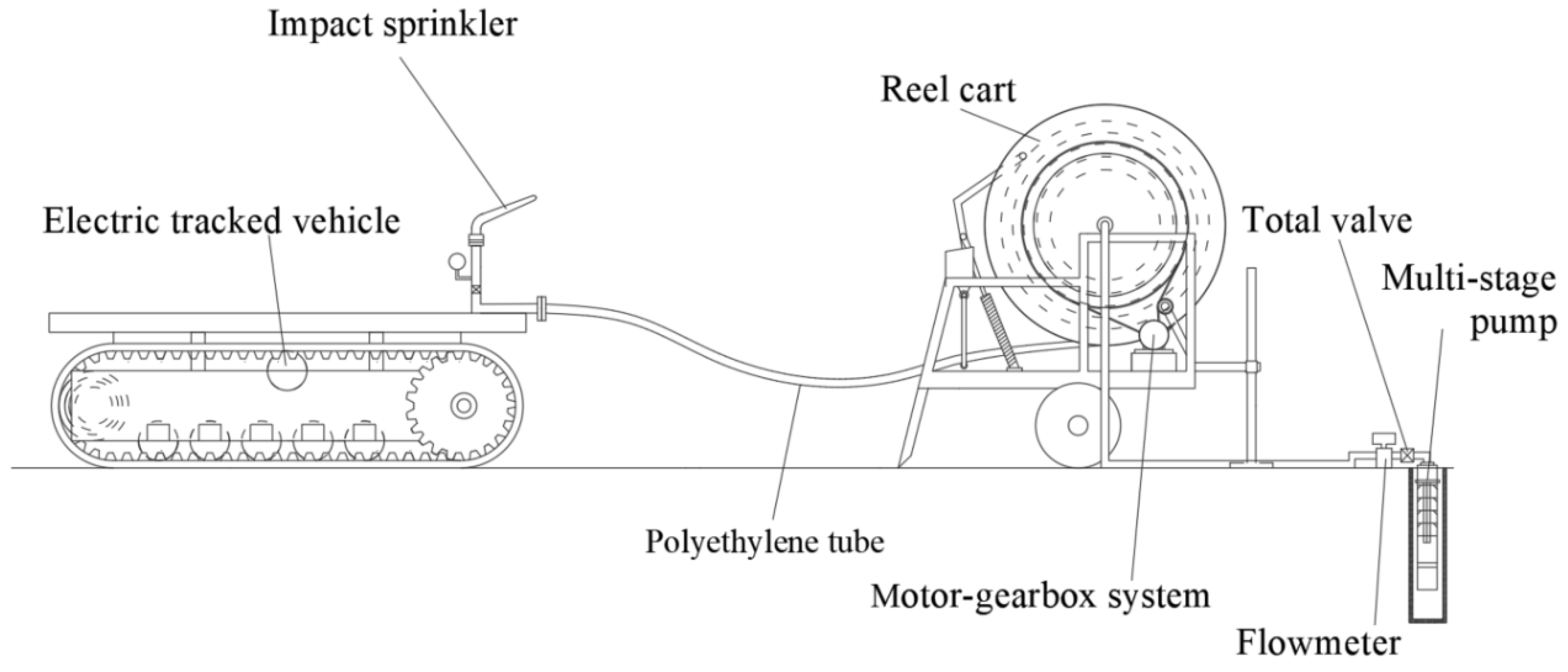
Figure 2.
A prototype of the self-propelled hard hose traveler.
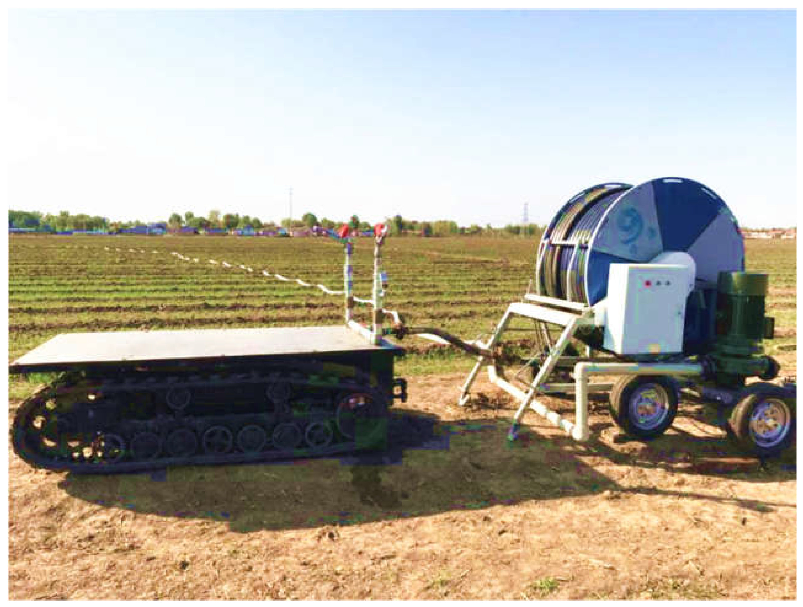
Figure 3.
Radial water distribution for different nozzles of the 40PY2 sprinkler.
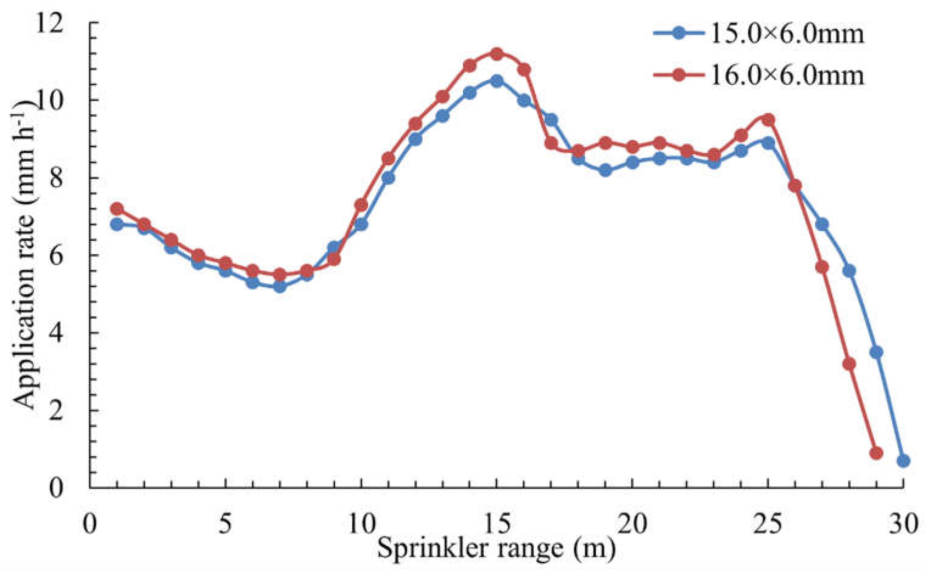
Figure 4.
Schematic diagram of motion sprinkler irrigation and the water reception at measurement point M.
Figure 4.
Schematic diagram of motion sprinkler irrigation and the water reception at measurement point M.
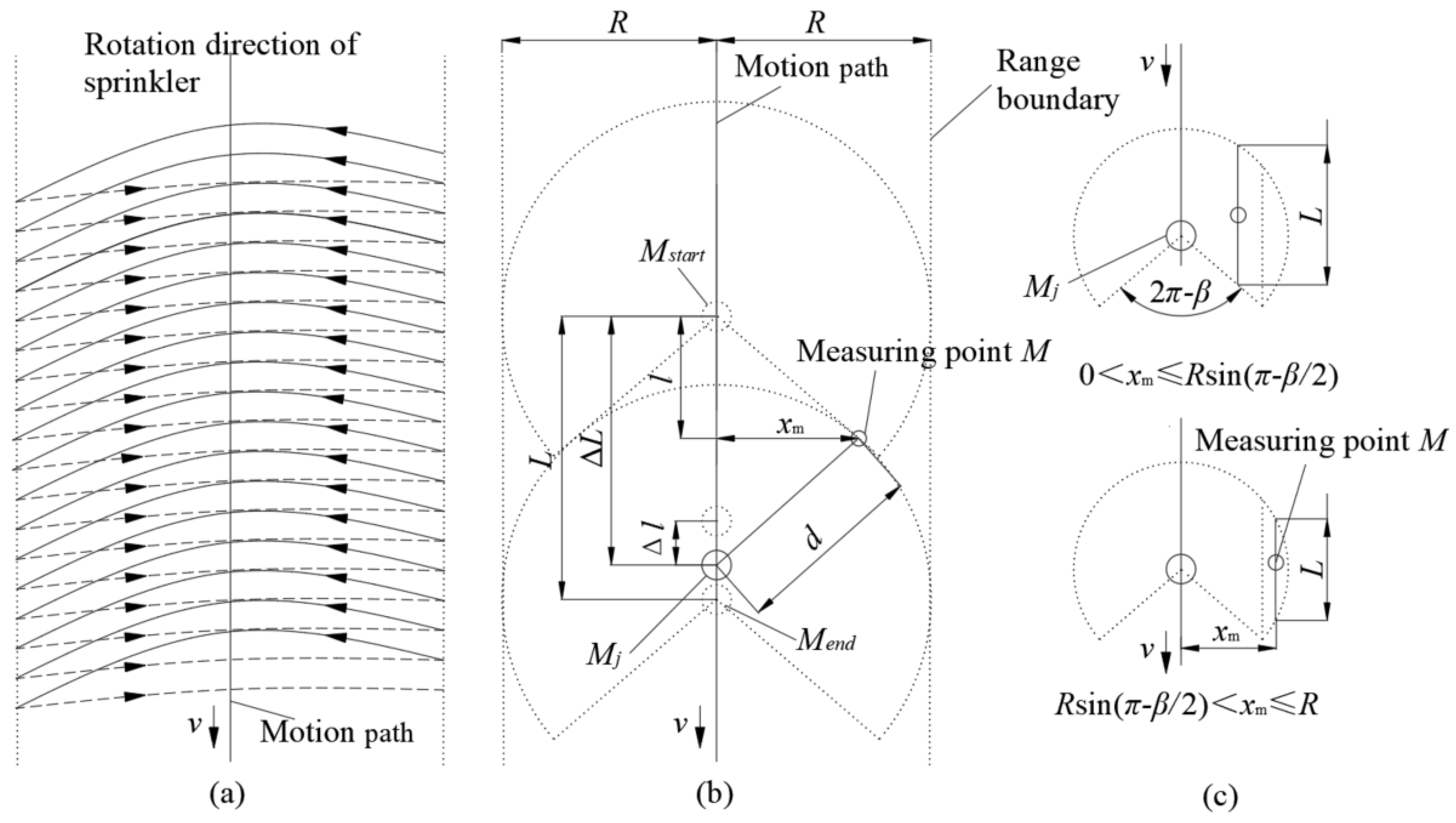
Figure 5.
Water buckets and the sprinkler irrigation experiment.
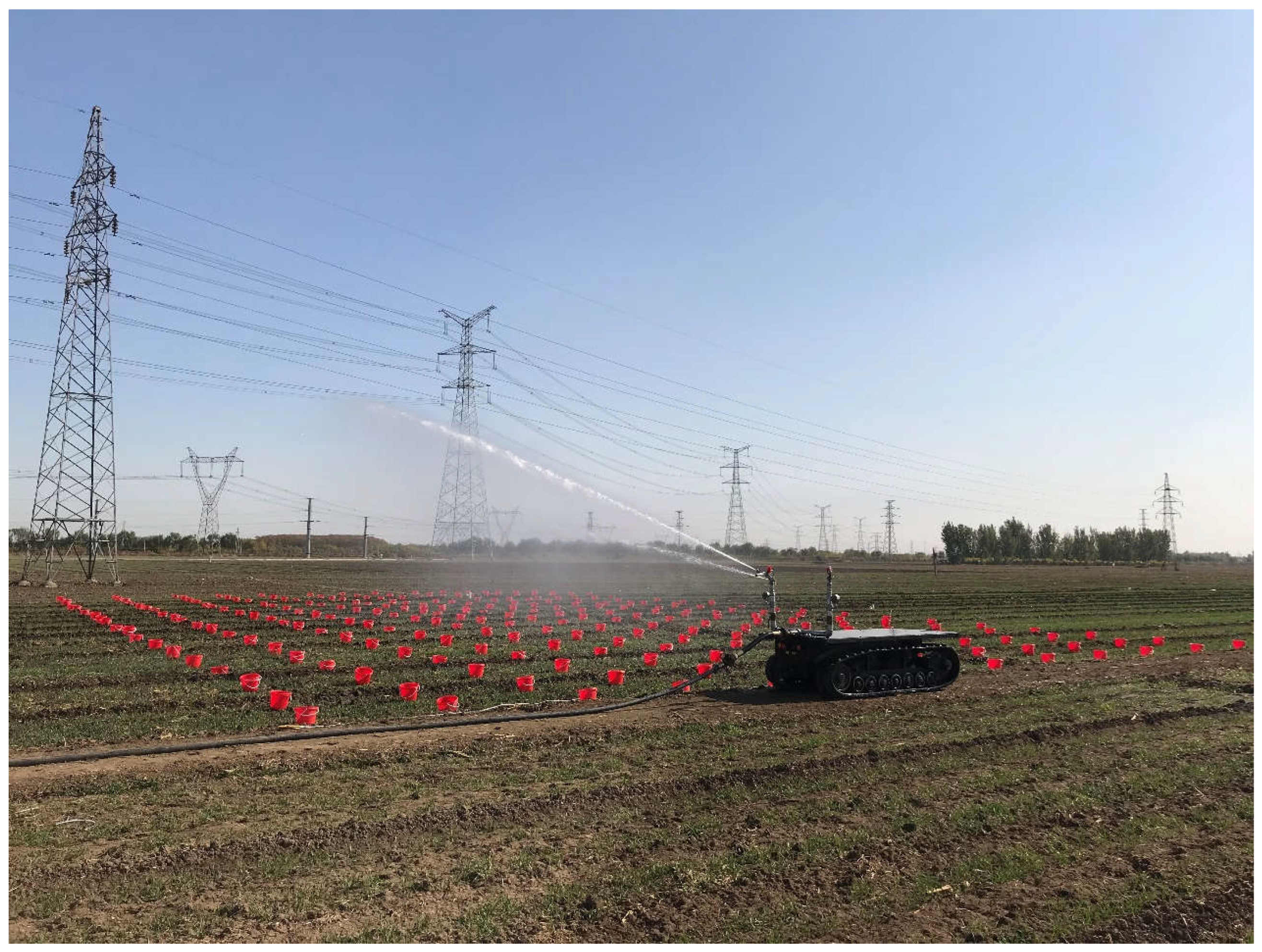
Figure 6.
The calculated and experimental values for irrigation water amounts.
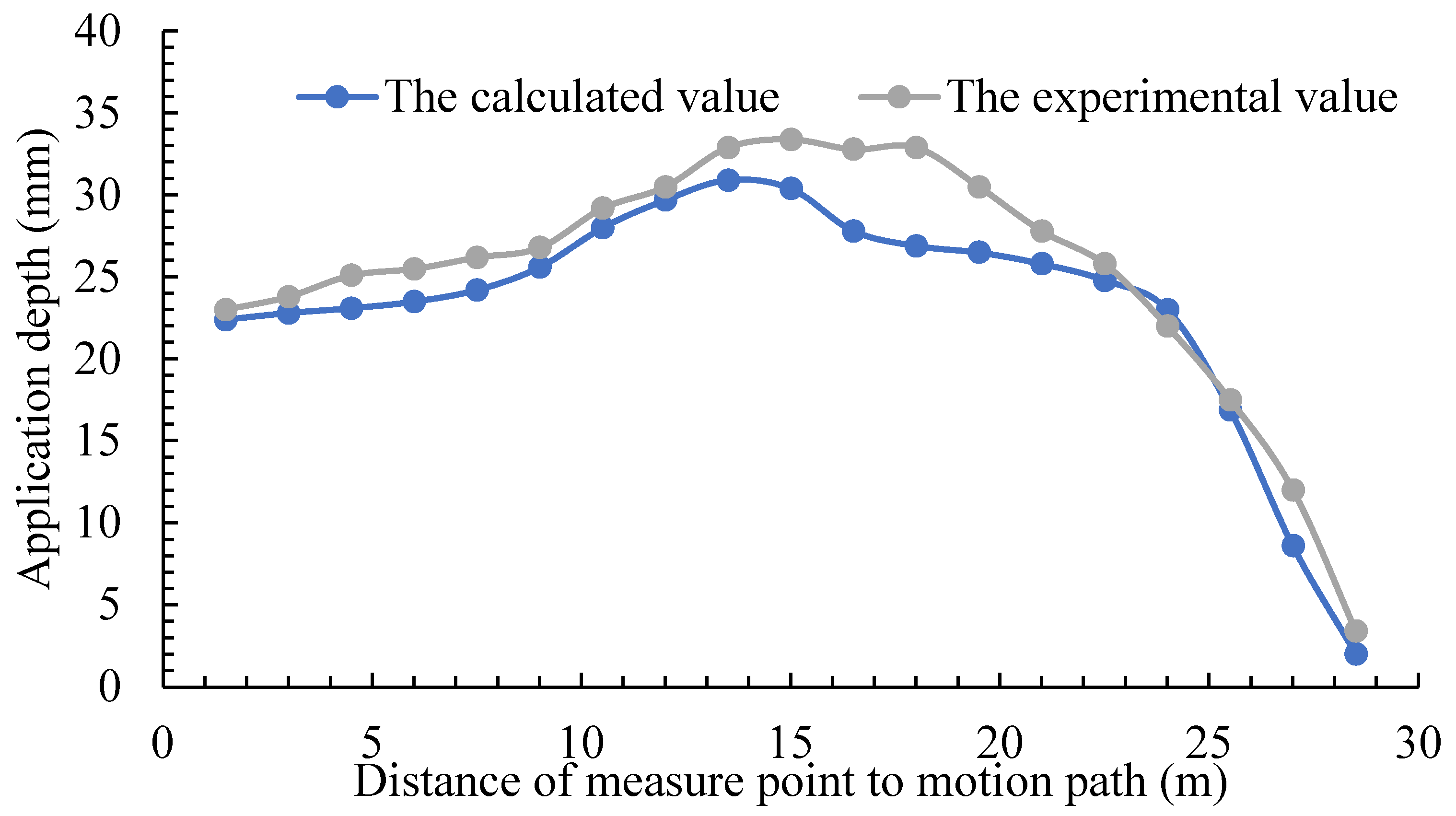
Figure 7.
Application depth of various nozzles of 40PY2 impact sprinkler.
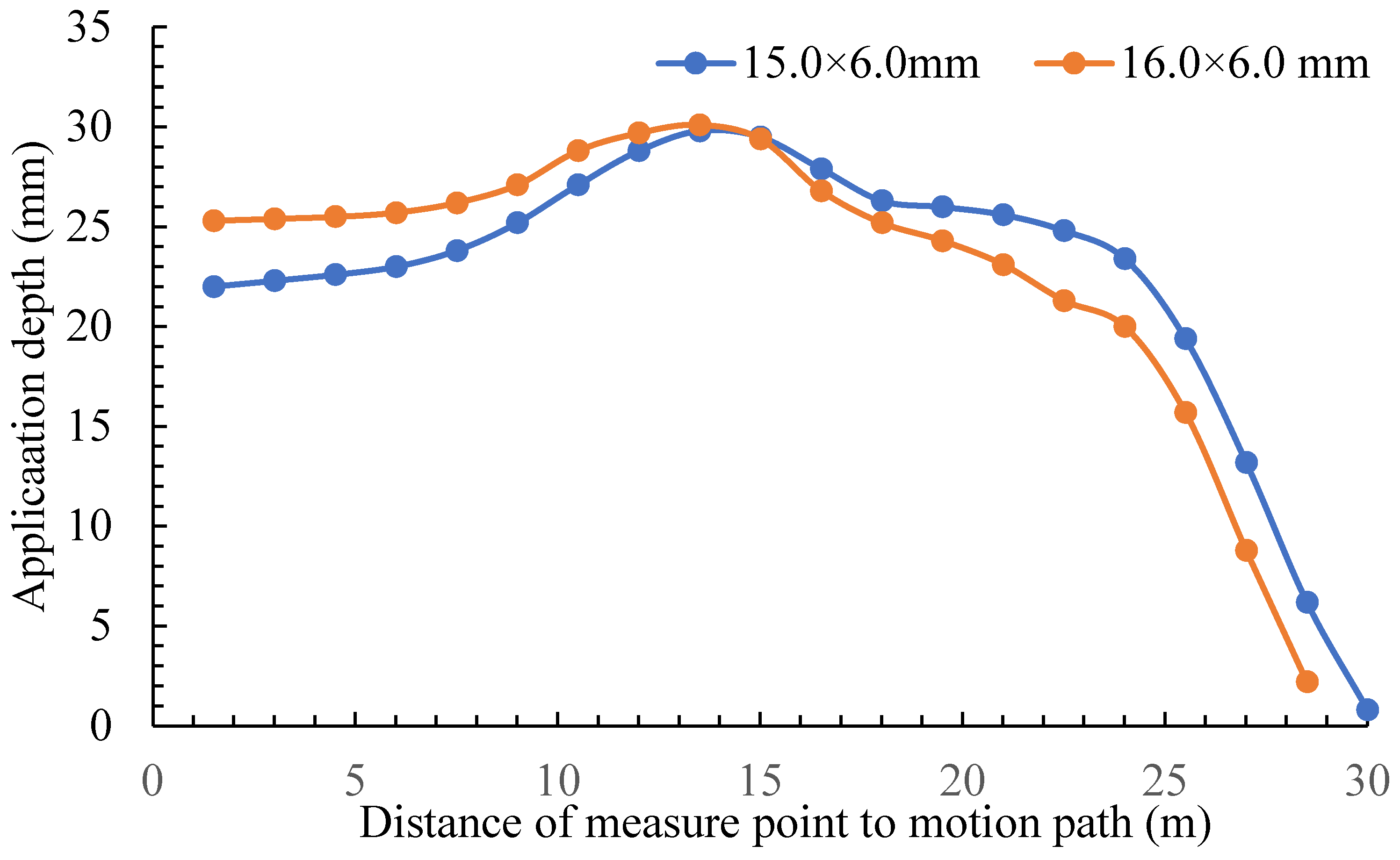
Figure 8.
Application depth at different motion speeds.
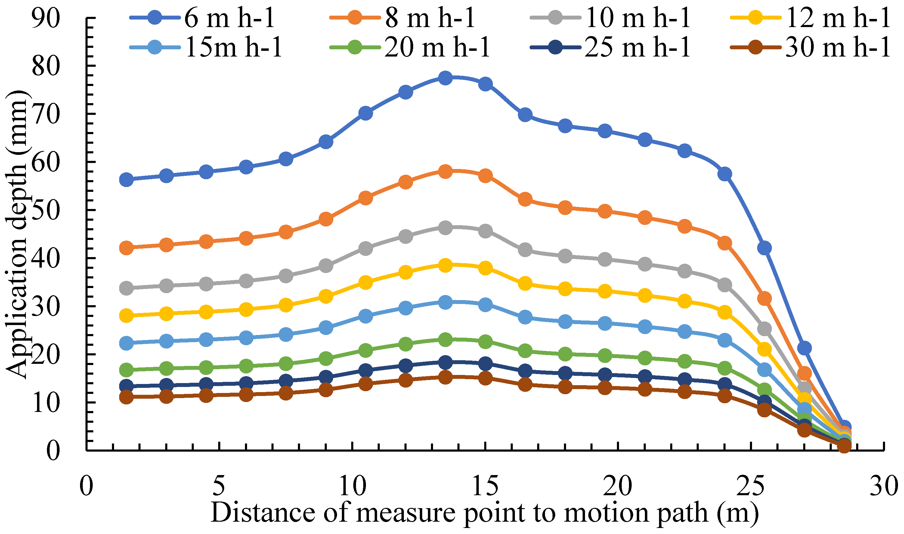
Figure 9.
Application depth at different rotation angle.
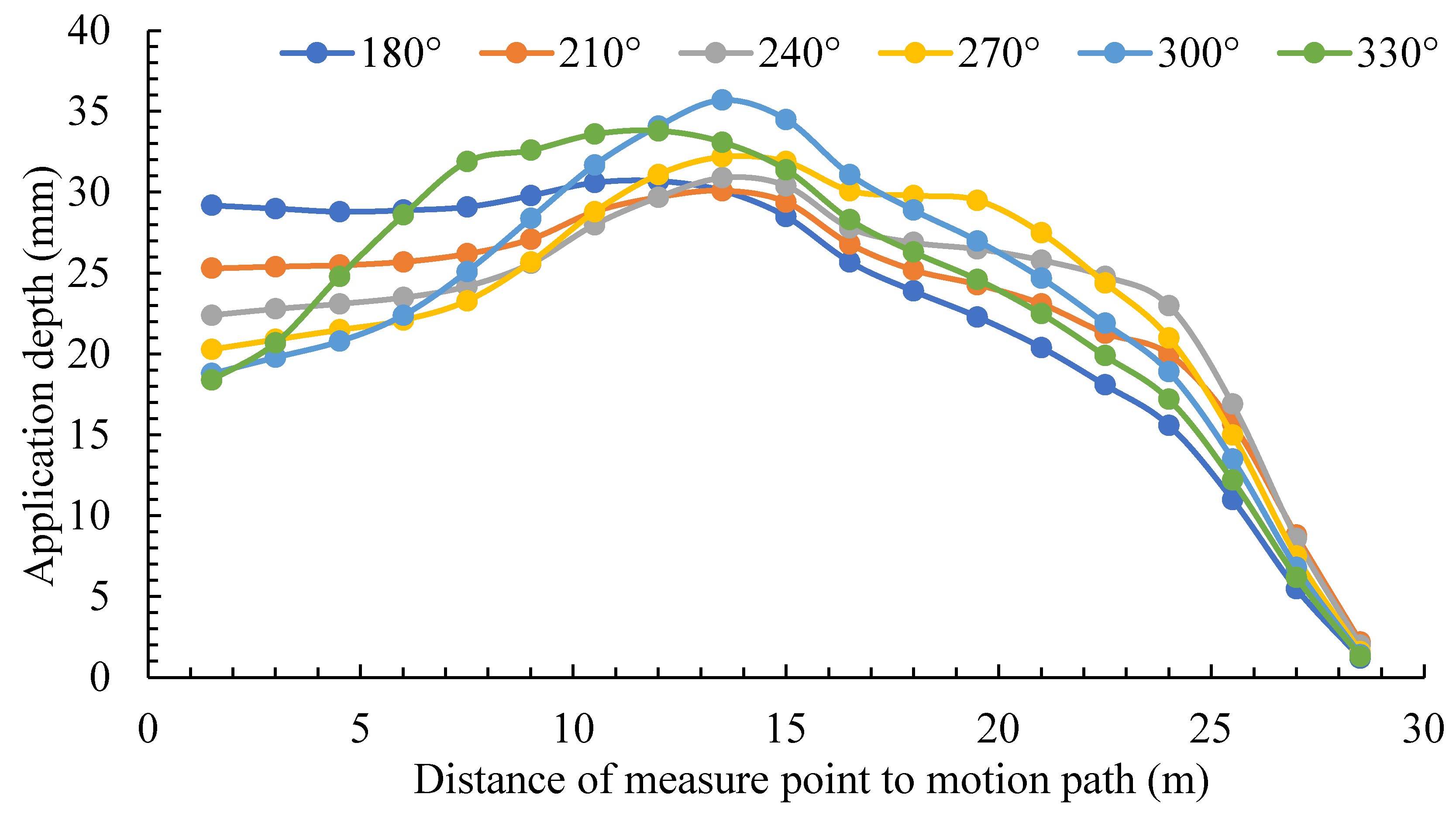
Figure 10.
Irrigation effect of a sprinkler moving along a specific path.
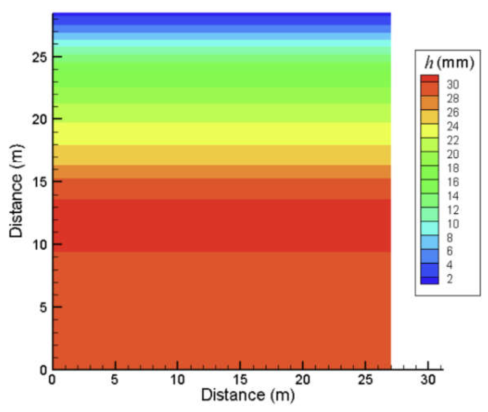
Figure 11.
Combined irrigation effect of motion sprinklers.
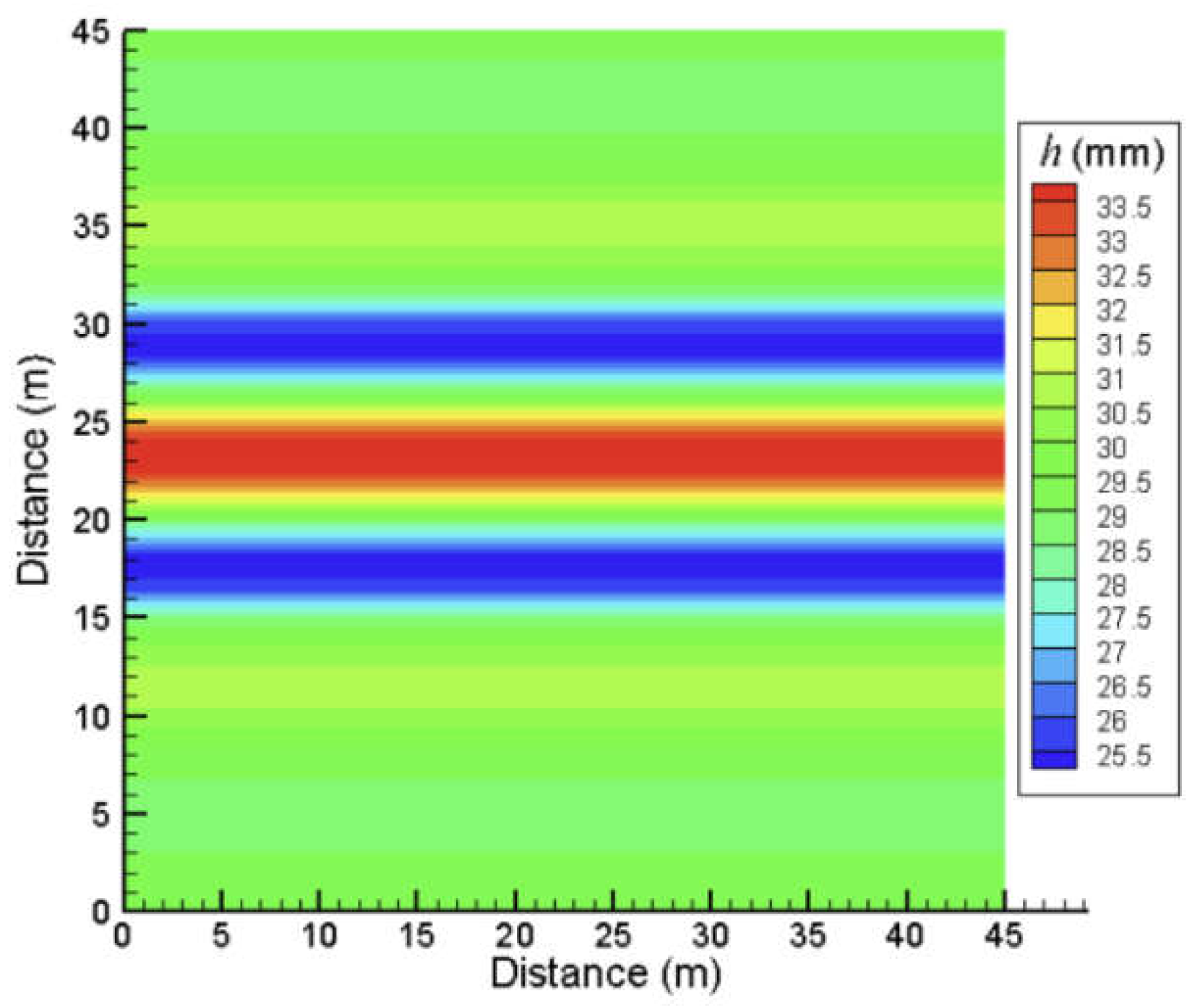

Table 1.
Average application depth and CU values of various nozzles of 40PY2 impact sprinkler.
| Nozzle diameter (mm) | Average application depth (mm) | CU value (°) |
|---|---|---|
| 15.0×6.0 | 22.4 | 74.9 |
| 16.0×6.0 | 23.3 | 80.0 |
Table 2.
Average irrigation amount and CU values at different motion speeds.
| Motion speed (m h−1) | Average application depth (mm) | CU value (%) |
|---|---|---|
| 6 | 58.5 | 79.9 |
| 8 | 43.8 | 79.9 |
| 10 | 35.0 | 80.0 |
| 12 | 29.2 | 79.9 |
| 15 | 23.3 | 80.0 |
| 20 | 17.4 | 80.0 |
| 25 | 13.9 | 80.1 |
| 30 | 11.6 | 80.2 |
Table 3.
Average application depth and CU values for different sprinkler rotation angles.
| Sprinkler rotation angle (°) | Average application depth (mm) | CU value (%) |
|---|---|---|
| 180 | 23.1 | 69.2 |
| 210 | 23.2 | 78.2 |
| 240 | 23.3 | 80.0 |
| 270 | 23.4 | 74.2 |
| 300 | 23.4 | 70.0 |
| 360 | 23.5 | 68.7 |
Table 4.
Average application depth and CU values of different nozzle diameters.
| Index | Nozzle diameter (mm) | Path spacing (m) | |||||||||
|---|---|---|---|---|---|---|---|---|---|---|---|
| 1.0R | 1.1R | 1.2R | 1.3R | 1.4R | 1.5R | 1.6R | 1.7R | 1.8R | 1.9R | ||
| Average application depth (mm) | 15.0×6.0 | 44.8 | 40.7 | 37.3 | 34.4 | 32.0 | 29.8 | 28.0 | 26.3 | 24.9 | 23.6 |
| 16.0×6.0 | 46.6 | 42.2 | 38.5 | 35.4 | 32.8 | 31.6 | 29.5 | 27.7 | 26.1 | 24.6 | |
| CU value (%) | 15.0×6.0 | 77.9 | 68.9 | 65.2 | 66.8 | 72.1 | 79.7 | 85.3 | 89.7 | 90 | 84.1 |
| 16.0×6.0 | 80.0 | 69.6 | 64.4 | 65.5 | 71.5 | 75.4 | 82.2 | 88.1 | 92.0 | 86.3 | |
Table 5.
Average application depth and CU value at different sprinkler motion speeds.
| Index | Motion speed (m h−1) | Path spacing (m) | |||||||||
|---|---|---|---|---|---|---|---|---|---|---|---|
| 1.0R | 1.1R | 1.2R | 1.3R | 1.4R | 1.5R | 1.6R | 1.7R | 1.8R | 1.9R | ||
| Average application depth (mm) | 6 | 117.0 | 105.8 | 96.6 | 88.9 | 82.3 | 79.4 | 74.1 | 69.5 | 65.4 | 61.7 |
| 8 | 87.7 | 79.3 | 72.4 | 66.6 | 61.7 | 59.5 | 55.5 | 52.1 | 49.0 | 46.3 | |
| 10 | 70.1 | 63.4 | 57.9 | 53.3 | 49.3 | 47.6 | 44.4 | 41.6 | 39.2 | 37.0 | |
| 12 | 58.3 | 52.8 | 48.2 | 44.3 | 41.1 | 39.6 | 36.9 | 34.6 | 32.6 | 30.8 | |
| 15 | 46.6 | 42.2 | 38.5 | 35.4 | 32.8 | 31.6 | 29.5 | 27.7 | 26.1 | 24.6 | |
| 20 | 34.9 | 31.6 | 28.8 | 26.5 | 24.5 | 23.7 | 22.1 | 20.7 | 19.5 | 18.4 | |
| 25 | 27.9 | 25.2 | 23.0 | 21.2 | 19.6 | 18.9 | 17.6 | 16.5 | 15.6 | 14.7 | |
| 30 | 23.1 | 20.9 | 19.1 | 17.6 | 16.3 | 15.7 | 14.7 | 13.7 | 12.9 | 12.2 | |
| CU value (%) | 6 | 80.0 | 69.5 | 64.4 | 65.5 | 71.5 | 75.4 | 82.2 | 88.1 | 91.9 | 86.2 |
| 8 | 80.0 | 69.5 | 64.4 | 65.5 | 71.5 | 75.4 | 82.2 | 88.1 | 91.9 | 86.3 | |
| 10 | 80.0 | 69.6 | 64.4 | 65.5 | 71.5 | 75.4 | 82.2 | 88.1 | 92.0 | 86.3 | |
| 12 | 80.0 | 69.5 | 64.4 | 65.5 | 71.5 | 75.4 | 82.2 | 88.1 | 92.0 | 86.3 | |
| 15 | 80.0 | 69.6 | 64.4 | 65.5 | 71.5 | 75.4 | 82.2 | 88.1 | 92.0 | 86.3 | |
| 20 | 80.1 | 69.6 | 64.5 | 65.5 | 71.5 | 75.4 | 82.2 | 88.1 | 92.1 | 86.4 | |
| 25 | 80.2 | 69.7 | 64.5 | 65.5 | 71.5 | 75.3 | 82.2 | 88.1 | 92.1 | 86.4 | |
| 30 | 80.3 | 69.8 | 64.5 | 65.6 | 71.5 | 75.4 | 82.2 | 88.1 | 92.1 | 86.5 | |
Table 6.
Average application depth and CU value of different sprinkler rotation angles.
| Index | Sprinkler rotation angle (°) | Path spacing (m) | |||||||||
|---|---|---|---|---|---|---|---|---|---|---|---|
| 1.0R | 1.1R | 1.2R | 1.3R | 1.4R | 1.5R | 1.6R | 1.7R | 1.8R | 1.9R | ||
| Average application depth (mm) | 180 | 46.1 | 41.8 | 38.1 | 35.1 | 32.5 | 31.3 | 29.2 | 27.4 | 25.8 | 24.4 |
| 210 | 46.4 | 42.0 | 38.3 | 35.2 | 32.6 | 31.5 | 29.4 | 27.5 | 25.9 | 24.5 | |
| 240 | 46.6 | 42.2 | 38.5 | 35.4 | 32.8 | 31.6 | 29.5 | 27.7 | 26.1 | 24.6 | |
| 270 | 46.8 | 42.3 | 38.6 | 35.5 | 32.9 | 31.7 | 29.6 | 27.8 | 26.1 | 24.7 | |
| 300 | 46.9 | 42.4 | 38.7 | 35.6 | 33.0 | 31.8 | 29.7 | 27.8 | 26.2 | 24.8 | |
| 330 | 47.1 | 42.6 | 38.9 | 35.8 | 33.1 | 32.0 | 29.8 | 28.0 | 26.3 | 24.9 | |
| CU value (%) | 180 | 83.9 | 79.0 | 78.5 | 82.3 | 88.7 | 92.1 | 95.0 | 90.6 | 83.2 | 76.1 |
| 210 | 83.2 | 75.0 | 71.1 | 72.5 | 78.3 | 82.1 | 88.1 | 91.6 | 92.4 | 85.7 | |
| 240 | 80.0 | 69.6 | 64.4 | 65.5 | 71.4 | 75.4 | 82.2 | 88.1 | 92.0 | 86.3 | |
| 270 | 74.3 | 64.3 | 60.0 | 61.9 | 68.7 | 72.9 | 79.9 | 85.2 | 85.7 | 80.0 | |
| 300 | 70.7 | 62.5 | 60.1 | 63.6 | 71.3 | 75.0 | 80.7 | 84.3 | 81.3 | 75.9 | |
| 330 | 73.6 | 68.5 | 69.2 | 73.8 | 81.3 | 84.2 | 86.3 | 86.1 | 80.9 | 75.0 | |
Table 7.
Summary of hydraulic parameters for self-propelled hard hose traveler (CU ≥ 85%).
| Number | Hydraulic parameters | Data |
|---|---|---|
| 1 | Flow rate (m3 h−1) | 19.7 |
| 2 | Sprinkler Model | 40PY2 |
| 3 | Number of Sprinklers | 1 |
| 4 | Nozzle diameter (mm) | 16.0×6.0、15.0×5.0 |
| 5 | Working pressure (kPa) | 450 |
| 6 | Sprinkler elevation angle (°) | 25 |
| 7 | Sprinkler range (m) | 28.5 |
| 8 | Motion speed (m h−1) | 6 ~ 50 |
| 9 | Variation in motion speed (m h−1) | 1 |
| 10 | Sprinkler rotation angle (°) | 180、210、240 |
| 11 | Path spacing (m) | 1.6~1.9 R |
Disclaimer/Publisher’s Note: The statements, opinions and data contained in all publications are solely those of the individual author(s) and contributor(s) and not of MDPI and/or the editor(s). MDPI and/or the editor(s) disclaim responsibility for any injury to people or property resulting from any ideas, methods, instructions or products referred to in the content. |
© 2025 by the authors. Licensee MDPI, Basel, Switzerland. This article is an open access article distributed under the terms and conditions of the Creative Commons Attribution (CC BY) license (http://creativecommons.org/licenses/by/4.0/).
Copyright: This open access article is published under a Creative Commons CC BY 4.0 license, which permit the free download, distribution, and reuse, provided that the author and preprint are cited in any reuse.


