Submitted:
17 March 2025
Posted:
18 March 2025
You are already at the latest version
Abstract
As a core component of modern mechanical transmission, rotary motion mechanisms and their drive systems have broad applications in aerospace, robotics, and other fields. This article systematically reviews the design principles, performance characteristics, and research progress of various rotary motion mechanisms and their driving technologies. The advantages, disadvantages, and applicable scenarios of traditional mechanisms such as gear mechanisms, drive belt mechanisms, sprocket mechanisms, cam mechanisms, ratchet and pawl mechanisms, and connecting rod mechanisms were analyzed in detail. The innovative design and application potential of new mechanisms, such as intermittent indexing mechanisms, magnetic gears, spherical gears, and multi-link mechanisms, were also explored. In addition, the paper provides a detailed comparison of the performance differences among electric, hydraulic, pneumatic, and other driving methods and summarizes the optimization directions for efficient driving systems. Research has shown that through material innovation, structural optimization, and intelligent control, there is still significant room for improvement in load capacity, accuracy, and reliability of rotary motion mechanisms, providing theoretical support and practical reference for future mechanical transmission technology development.
Keywords:
review
; rotating motion mechanism
; precision transmission
; mechanical design
; rotary drive
1. Introduction
The rotating motion mechanism is a key component for achieving power transmission and motion conversion, and its performance directly affects the efficiency and stability of mechanical systems [1,2,3,4,5]. With the rapid development of industrial automation, precision manufacturing, and robotics technology, the demand for high-load, low-noise, and high-reliability rotating mechanisms is becoming increasingly urgent. Although traditional mechanisms such as gears and belt pulleys are relatively mature, their vibration and wear problems under high dynamic conditions still need to be solved [6,7,8,9,10]. In recent years, the proposal of new mechanisms such as non-circular gears, magnetic gears, and spherical joints, as well as the application of technologies such as 3D printing and intelligent materials, have injected new vitality into the design of rotary motion mechanisms [11,12,13,14,15,16,17].
The driving method of the rotating motion mechanism is also a key factor determining its performance and application range [18,19,20]. The traditional driving methods mainly include motor drive, hydraulic drive, and cylinder drive. However, with the continuous improvement of performance requirements for rotating mechanisms, piezoelectric drives have made significant progress in the driving of micro-rotating mechanisms in microelectromechanical systems due to their fast response and high resolution, providing a new solution for micro nano scale rotational motion control [21,22]. Electro-hydraulic servo drive achieves precise control of load position, speed, force, and other parameters, significantly improving the accuracy and stability of traditional hydraulic drive [23,24].
This article aims to systematically review the research progress of existing rotating mechanisms, analyze their technical bottlenecks, and look forward to future development directions. By integrating mechanical design, materials science, and control theory, this article provides a comprehensive perspective for innovative design and optimization of rotary motion mechanisms to meet the diverse needs in complex engineering scenarios. Due to the impossibility of providing all articles on rotational motion mechanisms and driving devices, this article reviews as much research as possible and mainly analyzes representative mechanisms. The structure of this article is as follows: Section 2 will review the classification and development status of typical rotary motion mechanisms, and Section 3 will introduce some new types of rotary motion mechanisms. Section 4 provides an overview of the research on the rotary motion mechanisms drive system. Finally, based on existing research, a systematic examination of relevant research prospects is of great significance for the innovative development of rotary motion mechanisms, which can provide a reference for the design work of mechanical engineers.
2. The Development of Typical Rotating Motion Mechanisms
2.1. Gear Mechanism
The gear mechanism is one of modern machinery’s most widely used transmission mechanisms. A gear mechanism is a mechanical transmission mechanism that uses the meshing of gears to transmit motion and power. It has an extensive transmission power range, high efficiency, accurate transmission ratio, long service life, and safe and reliable operation [25]. In addition to high manufacturing costs and noise generation [26], gear transmission has significant advantages in operational characteristics compared to other mechanical transmissions. Gear mechanisms are particularly evident regarding operational safety, durability, efficiency, small size, and reliability, accounting for about 80% compared to other mechanical transmissions [27]. The classification of gear mechanisms is shown in Figure 1, adapted from [28].
2.1.1. Spur Gear Mechanism
As an essential transmission component, spur gears are widely used in automobiles and various mechanical equipment [29]. Spur gears can effectively transmit power in an ideal state, where the relative sliding between tooth surfaces during meshing is low, and high transmission efficiency is achieved [30]. In the power system of machine tools and the transmission chain of simple automatic transmission systems, multi-stage spur gear transmission can effectively change speed and torque [31].
By adjusting parameters such as the gear displacement coefficient and tooth crest coefficient, the gear contact ratio can be increased to 2 or above. This type of spur gear is called a high coincidence ratio (HCR) spur gear, as shown in Figure 2[32]. Compared with traditional spur gears with contact ratios between 1 and 2, HCR spur gears have more tooth pairs that mesh simultaneously during operation. This feature enhances their load-bearing capacity and reduces vibration and noise, making them particularly suitable for high-speed and heavy-duty applications.
2.1.2. Helical Gear Mechanism
The teeth of the inclined gear are spiral-shaped, and its gear profile is shown in Figure 3[33], forming a specific angle between inclined gear’s thread and the gear shaft. Spiral gears have a greater degree of overlap than spur gears, meaning more load distribution teeth are in the transmission process. Therefore, helical gears have good gear performance and long fatigue life and are widely used in mechanical power transmission [34].
Face gears can be used in cross-axis transmission systems. Compared with bevel gearboxes, face gears have unique advantages in rotary transmission, with little or no axial force [36]. The helical surface gear pair is a new type of gear pair consisting of helical non-circular, and helical, surface gears. Figure 4[37] shows that it can transmit variable transmission ratios between intersecting axes.
The worm gear mechanism consists of a turbine and a worm [39]. Due to its unique characteristics, including rapid deceleration in the smallest space [40], low noise [41], high motion stability [42], and high load capacity, worm gears are widely used in various industries [43,44]. Worm gearboxes in fields such as smart cars and smart homes can significantly reduce the weight of products [45].
Zhang XC et al. [46] designed an innovative biased worm gear transmission mechanism, as shown in Figure 5. The dual lead offset worm drive system can achieve linear contact conjugation between tooth surfaces, ensuring the accuracy of the instantaneous transmission ratio. Its transmission principle is simple and easy to implement. This transmission method not only inherits the advantages of traditional worm gear transmission (including offset worm gear transmission) but is also more flexible in adjusting the axial position. Whether it is the worm gear or worm wheel adjustment, it can effectively change the meshing clearance without interfering with the contact state of the conjugate tooth surface, simplifying the assembly process and providing adjustability of the meshing clearance.
Mu SB et al. [47] proposed a novel linear contact surface worm gear transmission mechanism consisting of a hardened cylindrical and surface worm gear, as shown in Figure 6. The worm gear is formed by grinding with a conical grinding wheel, and after hardening treatment, the surface wear resistance is significantly improved, extending its service life. The worm rotates around its axis, driving the surface worm wheel to rotate around the vertical axis, achieving non-orthogonal shaft transmission. The number of worm heads and worm teeth determines the transmission ratio. By replacing the traditional spiral-driven Archimedes worm with a conical enveloping worm, the problem of non-developable surfaces that cannot be precisely ground has been solved, improving hardness and accuracy. Determine the installation range of the worm gear through the meshing limit line function to ensure meshing stability. The wire contact design improves the load-bearing capacity and transmission efficiency. Numerical analysis shows that it has excellent lubrication performance, with a sliding angle close to 90 °, which is conducive to oil film formation. However, the asymmetry of the tooth surface may lead to vibration and noise, and cone grinding equipment requires precision and high manufacturing costs. The axial installation distance of the worm gear needs to be strictly adjusted. Otherwise, it will affect the meshing performance.
2.1.3. Conical Gear Mechanism
Straight bevel gears are widely used in the mechanical field for transmitting motion between orthogonal axes. According to the different inclined curves, it can be divided into circular spur bevel gears (CSB-gear) and non-circular spur bevel gears (NCSB-gear). Cone gears generate axial force during transmission, producing significant vibration and noise during high-speed operation. They are usually used under conditions of low transmission speed and light load. A non-circular spur bevel gear is a special type of spur bevel gear that can be used for gear shifting. It can perform special functions, such as the anti-slip function of the car differential, which circular spiral bevel gears cannot achieve. Its model is shown in Figure 7.
Due to its high load-bearing capacity, high sealing coefficient, and low noise, spiral bevel gears are often used in automotive drives and reducers. At present, spiral limestone wheels are divided into two types of gear systems: one is a circular bevel gear with a circular tooth profile shape, and the tooth profile height decreases along the tooth length. Another type of cycloidal bevel gear has a tooth profile that extends outward, with the height of the tooth profile equal to the length of the tooth. The cycloidal bevel gear is shown in Figure 8[49].
2.1.4. Hyperbolic Gear Mechanism
The hyperbolic gear mechanism is widely used in various automotive drive systems. The main difference between them and spiral bevel gears is that the former has two spatial displacement axes, and the distance between the two axes is called hyperbolic bias. Introducing slight gear bias transforms a planar helical gear into a spatial hyperbolic gear, which has significant advantages such as improving the strength of the small gear, improving the contact ratio, and flexibly adjusting the height of the car chassis. However, the biggest drawback is that the sliding ratio will increase, as shown in Figure 9[50].
2.1.5. Spherical Gear Mechanism
Liang GQ et al. [52] proposed a driving integrated spherical gear (DISG), as shown in Figure 10. DISG consists of a pair of spherical gears and an omnidirectional internal drive. It projects traditional planar gears’ circular involute and bevel gear combination profile onto the spherical surface to achieve global meshing and driving. The active driving and passive following magnets are connected across the ball through magnetic force. The active magnet moves inside the ball to drive the passive magnet, pushing the two spherical gears to roll purely. Two spherical gears can roll in any direction, forming a multi-degree of freedom joint that achieves full range motion without singularities by changing the contact point position. The combination of active and passive magnets replaces mechanical connections, allowing for arbitrary switching of contact points, eliminating the limitations of external frames, and improving the degree of freedom of motion. Integrating 3D-printed spherical gears and magnetic drive systems reduces weight and volume, making it suitable for high-density integration scenarios. However, the output torque of the magnetic drive system is relatively low (measured at 0.39 N · m), and it is necessary to enhance the magnet or optimize the tooth profile to improve the load capacity. 3D printing gears require high precision, and tooth surface wear may lead to uneven transmission.
Tanaka T et al. [53] introduced and manufactured a new type of spherical gear mechanism, as shown in Figure 11. This spherical gear achieves multi-degree of freedom motion through a specially designed tooth profile (imitating involute tooth profile), allowing the drive shaft and driven shaft to mesh and transmit power at different shaft angles (0 ° to 74 °). Its tooth profile is uniformly distributed along the spherical surface, and the tooth thickness gradually decreases with the increase of contact angle, ensuring stable meshing at different angles. The hollow design inside the gear reduces weight. Compared with traditional complex spherical gears, this design uses a handle similar to a spur gear, simplifying manufacturing and assembly and improving versatility. Supports multi-axis angles (up to 74 °). Made using 3D printing technology (ABS resin), it reduces the production difficulty of complex shaped gears and shortens the cycle time (about 50 hours). However, there are also some drawbacks, such as a decrease in transmission efficiency and a significant increase in clearance when the shaft angle increases. 3D printing can lead to substantial differences in tooth thickness errors and surface roughness. Need to rely on fixtures to adjust the axis angle, with limited flexibility in practical applications.
2.1.6. Non Circular Gear Mechanism
Non-circular gears are typical gear mechanisms that can achieve non-uniform transmission and have been widely used. They have the advantages of high transmission accuracy and compact size [54]. Mundo D. [55] proposed a new concept of nonlinear planetary transmission, as shown in Figure 12. The planetary gear system consists of three non-circular gears (sun gear, planetary gear, ring gear), which achieve variable transmission ratios through the geometric design of non-circular pitch curves. The degrees of freedom of the planetary gear system are achieved by fixing the sun gear or ring gear to achieve different input/output configurations, supporting four transmission modes, and flexibly adjusting the relationship between torque and speed. Combining the variable transmission ratio characteristics of non-circular gears with the compactness of planetary gear systems to achieve high dynamic transmission requirements. By defining the transmission ratio function through the Fourier series and combining it with numerical integration, interference-free tooth profiles are generated to ensure meshing stability.
The schematic diagram of the non-circular gear mechanism proposed by Yu GH et al. [56] is shown in Figure 13. This conjugate concave-convex non-circular gear mechanism consists of a driving wheel and a driven wheel and achieves variable speed transmission through the meshing of non-circular pitch curves. When the driving wheel rotates, the conjugate tooth profile generated by the generation method ensures smooth meshing, where the gear teeth adopt an involute tooth profile, and the concave part adopts a transition curve similar to a cam. Use the Gaussian function superposition method to define the transmission ratio and flexibly adjust the position and size of two unequal peaks. The transmission ratio has an extensive dynamic range and can meet special motion requirements. There may be slight errors in the transmission ratio within specific ranges.
2.1.7. Linear Gear Mechanism
The line gear based on conjugate space curve theory is a new gear mechanism very suitable for compact space transmission. Chen YG et al. [57] proposed a novel non-circular linear gear mechanism, whose structure is shown in Figure 14, and the effect is shown in Figure 15. A new design method for variable speed non-circular gears (VLG) based on spatial curve meshing theory, combined with constant speed ratio (CSR) and variable speed ratio (VSR) linear teeth, is proposed to achieve smooth transmission ratio conversion within one rotation cycle. A cylindrical or conical spiral is the contact curve to ensure a constant speed ratio. A smooth transition of speed ratio is achieved through non-circular teeth. Segmented quartic curves ensure continuous angular acceleration and impact during transmission, thereby avoiding separation or effects. Simple structure, small size, suitable for micromechanical and lightweight applications, with a wide range of speed ratio changes and zero sliding design, which can reduce wear and extend service life. Segmented curve control is suitable for high-temperature, low-temperature, or vacuum environments, ensuring no impact and smooth movement during transmission. Figure 16 also shows a typical linear gear transmission structure [58].
2.1.8. Non Relative Sliding Gear Mechanism
Chen Z et al. [59] proposed a design of non-relative sliding gears for transmitting parallel axes. Figure 17 is a physical photo of the gear, and Figure 18 shows its working characteristics. This non-relative sliding gear mechanism is designed based on the functional positioning of the meshing line. Pure rolling contact of parallel axis transmission was achieved, significantly reducing friction and temperature rise. Using helical motion to generate cylindrical helical surfaces with equal or variable pitch simplifies the design process and improves flexibility. The concave-convex arc tooth surface design significantly reduces contact stress compared to involute gears. The non-relative sliding gear mechanism reduces sliding friction, improves transmission efficiency and service life, has low contact stress, is suitable for high load scenarios, is flexible in design, and can adapt to different motion requirements by adjusting the meshing line function.
2.1.9. Double Cycloidal Gear Mechanism
Shin JH. [60] proposed a new prestressed gear mechanism, as shown in Figure 19. The double cycloidal gear mechanism adopts a cycloidal profile design instead of traditional involute gears. It utilizes the low sliding speed during cycloidal meshing to achieve smooth transmission under impact loads. Gear design is based on the principle of double cycloid meshing, which optimizes the contact trajectory by adjusting parameters such as tooth number difference and modulus, reducing tooth surface interference and deformation. The double cycloidal gear mechanism has strong impact resistance and small tooth surface deformation, making it suitable for high dynamic load applications.
2.1.10. Magnetic gear mechanism
Traditional mechanical gears have contact surfaces between gear teeth, which can lead to energy consumption, noise, and vibration [61]. Yin X et al. [62] proposed a novel coaxial magnetic small gear, which only fixes one layer of permanent magnet, as shown in Figure 20. The coaxial magnetic gear adopts a single-layer static, permanent magnet array combined with magnetic flux modulation teeth made of high-temperature superconducting (HTS) material. The external magnetic field is repelled through the ideal diamagnetism of high-temperature superconductivity, reducing magnetic leakage and concentrating magnetic flux. The relative motion between the inner and outer rotors generates a harmonic magnetic field through magnetic flux modulation, achieving non-contact torque transmission. After optimizing parameters such as tooth thickness and permanent magnet thickness, the torque density was significantly improved, and the maximum output torque reached 1.73 times that of traditional ferromagnetic tooth structures. HTS teeth replace ferromagnetic materials, utilizing their ideal diamagnetism to reduce end effects and leakage, improve magnetic flux utilization, eliminate mechanical contact, reduce wear and noise, and are suitable for high-precision scenarios. High-temperature superconducting materials require low temperatures (77K) to maintain superconductivity, rely on cooling systems, and have high costs.
Jing LB et al. [63] provide a new structure to increase the torque of magnetic gears, as shown in Figure 21. The magnetic gear comprises an inner and outer rotor and a magnetic modulation ring. The magnetic modulation circuit regulates the internal and external air gap magnetic fields to couple the internal and external rotor magnetic fields and achieve torque transmission. The inner rotor adopts radial magnetization surface mounted permanent magnets. In contrast, the outer rotor adopts tangential magnetization spoke type permanent magnets, which improve the air gap magnetic density through magnetic flux focusing effect. To ensure torque transmission, the slotted outer rotor reduces the number of iron cores, reduces weight, and improves torque density. By improving the design of the magnetic modulation circuit, the coupling efficiency of harmonic magnetic fields has been significantly improved, and the torque output capability has also been enhanced.
Superconducting materials can increase torque density compared to permanent magnets [64]. Dong K et al. [65] proposed a novel axial flux modulated superconducting magnetic gear (AFMSMG), as shown in Figure 22. Axial flux modulation superconducting magnetic gear (AFMSMG) uses superconducting block magnets (SBM) instead of traditional permanent magnets, utilizing the high critical current density and ideal diamagnetism of superconducting materials to form a strong magnetic field at low temperatures. Through axial magnetic flux design, the interaction between the inner and outer rotor magnetic fields and the fixed modulation ring generates harmonic magnetic fields, achieving non-contact torque transmission with a torque density more than twice that of traditional magnetic gears. The non-contact transmission reduces wear, has a long lifespan, and is suitable for high-precision applications. Superconducting properties are stable at low temperatures and ideal for unique environments. Cooling conditions below 77K are required, which increases costs and system complexity. Compared to traditional solutions, the cost of superconducting materials and cooling systems is much higher.

Table 1.
Comparison of different types of gear mechanisms.
| Types | Advantages | Disadvantages | Applications |
|---|---|---|---|
| Spur gear [28,29,30] |
High transmission efficiency, simple structure, low tooth surface sliding | High noise level, significant vibration under high load | Machine tool power system, multi-stage transmission device |
| HCR spur gear [32] | High load-bearing capacity, low vibration, and noise | Need to adjust gear parameters (displacement coefficient) | Industrial machinery, heavy-duty transmission systems |
| Helical gear [33,34,35] |
Uniform load distribution, long lifespan, smooth transmission | Generate axial force, requiring additional bearing support | Reducer, General Industrial Equipment |
| Face gear [36,37,38] |
No/low axial force, variable transmission ratio | Asymmetric tooth surface may cause vibration | Robot joints, non-orthogonal axis transmission system |
| Worm gear [39,40,41,42,43,44,45,46,47] |
High deceleration ratio, low noise, high stability, auto-lock | High sliding friction, low efficiency, lubrication required | Elevators, car steering systems, heavy machinery |
| Straight bevel gear [48] | Simple and Reliable, non-circular spur bevel gears can achieve special functions | High-speed noise is loud and requires axial fixation | Low-speed light load transmission |
| Spiral bevel gear [49] |
High load-bearing capacity, high compatibility, and low noise, smooth transmission | High cost, accurate alignment, and installation are required | Automotive drive axles and reducers |
| Hypoid gear [50,51] |
The chassis height can be flexibly adjusted, high contact rate | Large sliding ratio, easy to wear, requires lubrication | Automotive drive systems, high offset transmission |
| Spherical gear [52,53] |
Multi degree of freedom, lightweight structure | Low output torque, efficiency decreases with increasing shaft angle | Robot flexible joints, drone gimbal, medical minimally invasive surgical equipment |
| Non- circular gear [54,55,56] |
Non-uniform variable speed, high transmission accuracy, compact structure, fast dynamic response | Complex processing and high cost, uneven stress on the tooth surface, prone to local wear | Printing machines, textile machinery, variable transmission bicycles |
| Linear gear [57,58] |
Small size, suitable for micro machinery, wide speed ratio range, zero slip design | High load performance to be verified | High temperature/vacuum environment transmission, micro-robots, lightweight equipment |
| No relative sliding gear [59] | Pure rolling engagement, low friction, low contact stress, and long lifespan | The manufacturing accuracy requirements are extremely high, and installation error sensitivity | High-load precision transmission |
| Double cycloidal gear [60] | Strong impact resistance and minimal tooth surface deformation, smooth transmission, and low noise | The dynamic response needs to be optimized, there may be a delay in the initial meshing | Car seat belt tensioner, high dynamic load machinery |
| Magnetic gear [61,62,63,64,65] |
Contactless transmission, zero wear, low noise, Maintenance free | Dependent on superconducting materials, high manufacturing costs, and complex systems | Precision instruments, renewable energy systems, non-contact transmission |
By comparing the tables, we can understand that the research status of gear mechanisms presents a diversified development trend, and various types of gear continue to make breakthroughs in structural optimization, material innovation, and precision manufacturing to meet the needs of high efficiency, low noise, and high reliability. Traditional gears, such as helical and spiral bevel gears, have improved their load capacity and noise reduction performance through improved tooth profile design. However, they are still limited by axial force, friction loss, and installation accuracy. Emerging gears such as magnetic gears and cycloidal gears have emerged in precision instruments and dynamic load scenarios due to their characteristics of non-contact transmission and pure rolling meshing. However, they face challenges such as strong material dependence and complex manufacturing. Noncircular gears and spherical gears have expanded their applications in fields such as robotics and medical equipment through non-uniform variable speed and multi-degree of freedom design. In contrast, micro-linear gears have promoted the lightweight of micromechanical systems. The future trend will focus on integrating intelligent algorithms to optimize dynamic response, developing self-lubricating materials to reduce friction losses, and using additive manufacturing technology to solve complex tooth profile machining problems while balancing the contradiction between high load capacity and low cost, promoting the development of gear mechanisms towards high efficiency, intelligence, and stronger environmental adaptability.
2.2. Drive Belt Mechanism
2.2.1. V-Belt
Since its introduction in the late 1970s, V-belt drive systems have become increasingly important in the automotive industry [66]. V-belt transmission has the advantages of flexible design, strong output stability, strong absorption capacity, large transmission ratio, overload protection, lubrication, pollution, and high cost-effectiveness. It is widely used in advanced mechanical transmission systems such as automobiles, ship engines, and industrial robots [67,68,69].
Ruan SH et al. [70] combined belt drive with a triboelectric nanogenerator (TENG) and proposed an intelligent triboelectric V-belt drive (TVB) system, as shown in Figure 23. TVB combines a V-belt drive with TENG, which is embedded in an independent mode at the bottom of the pulley. During operation, the V-belt periodically contacts and separates from the copper electrode at the bottom of the pulley, generating an AC signal through frictional charging. The signal output characteristics are related to load resistance, speed, and preload distance and can be used for real-time monitoring of the transmission system status. TENG is integrated at the bottom of the pulley, eliminating the need for additional space and avoiding direct contact with the working surface of the V-belt, significantly improving reliability and lifespan.
2.2.2. Synchronous Belt
Chen JN et al. [71] proposed a novel nonlinear drive, which includes an active circular pulley, a driven eccentric pulley, and a non-circular tension pulley, as shown in Figure 24. The new non-circular synchronous belt transmission mechanism consists of an active circular wheel, a driven eccentric wheel, and a non-circular tensioner wheel. Traditional non-circular synchronous belts suffer from severe belt slack due to the non-circular shape of the pulleys. The tension wheel compensation mechanism significantly reduces belt slack, improves transmission stability, and is smoother than non-circular chain transmission, making it suitable for environments with poor lubrication conditions. However, additional tensioning wheels are required, increasing the installation and maintenance difficulty.
Table 2.
Comparison of Belt Transmission Mechanisms.
| Types | Advantages | Disadvantages | Applications |
|---|---|---|---|
| Traditional V-belt drive [66,67,68,69] | Vibration absorption, high transmission ratio, overload protection | Low reliability, short lifespan | Automobiles, ship engines, industrial robots, etc. |
| V-belt drive (TVB system) [70] | Real-time monitoring and fault diagnosis, high reliability, and long lifespan | Affected by high humidity or high-temperature environment | Conveyor belts and small mechanical transmissions that require long-term monitoring |
| Synchronous belt drive (traditional non-circular) [71] | Specific non-uniform motion or velocity variation | The belt is loose and the transmission stability is poor | Machinery requiring non-uniform transmission |
| Synchronous belt drive (new nonlinear) [71] | Maintain tension on the belt; High stability, suitable for environments with poor lubrication | Extra non-circular tensioning wheels are required, with a complex structure | Machinery with precise speed changes for long-distance transmission |
By comparing the tables, we can understand that the research status of the belt transmission mechanism presents diversified development. Traditional V-belt transmission is still widely used in fields such as automobiles and industrial robots due to its shock absorption, high transmission ratio, and overload protection characteristics. However, its low reliability and short life limit its application in harsh environments. In recent years, intelligence and structural innovation have become the main trends: TVB systems have significantly improved reliability and lifespan by integrating real-time monitoring and fault diagnosis functions, but environmental adaptability still needs to be optimized. Although traditional non-circular types can achieve non-uniform motion in synchronous belt transmission, they face the challenge of insufficient transmission stability. However, the new nonlinear synchronous belt transmission exhibits high stability in poorly lubricated environments by maintaining tension and optimizing structural design. However, its complex structure and additional tensioning wheel requirements increase the application threshold. The future development direction will focus on the deep integration of intelligent monitoring technology and lightweight improvement of materials and structures to balance performance and complexity and enhance durability in extreme environments, thereby promoting the high-end application of pulley transmission in precision manufacturing, long-distance transmission, and automation fields.
2.3. Chain Wheel Mechanism
2.3.1. Single-Row Chain Drive
The chain drive transmits the driving force of the motor to the rotating actuator, and the basic structure of modern chains was first designed and proposed by the great scientist and artist Leonardo da Vinci during the European Renaissance. The sleeve roller chain adds sleeves and rollers, reduces wear, dramatically extends the service life of the chain, and is widely used in this mechanism [72]. As shown in Figure 25, the chain consists of alternating inner and outer rings. The chain pitch is the distance between two consecutive sleeve shafts [73].
The typical drive of the chain is shown in Figure 26. The drive wheel is on the right side, and the drive wheel is on the left. Drive the gear to rotate clockwise. Therefore, the tight chain is used as a rising chain to transfer the load, and the bottom is relaxed. The end of the chain represents the transition between the chain teeth and the sprocket.
2.3.2. Multi Row Chain Drive
Cheng WJ et al. [74] mentioned multi-row sprockets with flanges, as shown in Figure 27. The core of this article is the cold semi-precision forging process of 5052 aluminum alloy multi-row sprockets. By designing a new type of sprocket tooth profile and using circular arc transition instead of traditional sharp tooth tips, stress concentration and crack risk in the mold cavity have been reduced. Propose a three-step forging process, pre-forming teeth, machining flange grooves, and final forging, to simplify operations and improve mold filling efficiency. Cold forging technology reduces material waste and heat treatment requirements, lowering production costs. The new tooth profile and segmented forging have improved dimensional accuracy.
2.3.3. Silent Chain Drive
The silent chain transmissions in the specific automotive engine shown in Figure 28 have the advantages of low noise, high transmission accuracy, high transmission efficiency, and good durability and are widely used in automotive engines, transmissions, machine tools, and other high-speed transmission devices [75].
Cheng YB et al. [76] proposed a novel dual-phase single-toothed chain plate bidirectional chain transmission system. Based on the dynamic model shown in Figure 29. Adopting dual chain and dual phase sprockets, the polygonal effect is suppressed by phase difference, vibration is reduced, and transmission stability is improved. The dual chain design enhances wear resistance and load capacity. The chain plate only has a single tooth meshing, breaking through the limitations of traditional double tooth design, simplifying the structure and reducing weight, and verifying transmission stability through dynamic simulation. Optimize the shape of the chain plate and pin shaft, reduce system weight (by 23.3%), and meet lightweight requirements.
2.3.4. Composite material chain drive
Krithikaa D et al. [77] proposed an E-glass fiber-reinforced interpenetrating polymer network (IPN) composite chain plate for transmitting low loads, as shown in Figure 30. Using E-glass fiber reinforced IPN resin instead of traditional iron chain plates, it is 60% lighter than iron chain plates and reduces system energy consumption. Adjusting the ratio of vinyl ester to polyurethane allows a balance between stiffness and elasticity, which is superior to metal chain plates in noise reduction and vibration reduction. Verify the fatigue life of chain plates under different resin ratios. IPN resin is resistant to chemical corrosion and suitable for harsh environments. Adjust mechanical properties through resin ratio to meet various load requirements. The increase in PU ratio leads to an increase in elasticity, a decrease in fatigue resistance, and complex processing techniques that require manual layering and precise resin mixing. The manufacturing cost of composite materials is higher than that of traditional metals.
Table 3.
Comparison of different types of chain transmission mechanisms.
| Types | Advantages | Disadvantages | Applications |
|---|---|---|---|
| Single row chain drive [72,73] | Simple structure, easy maintenance, long lifespan, and low cost | High noise, lubrication required, low precision, and easy to vibrate at high speeds. | Bicycles, motorcycles, and other low-load scenarios |
| Multi row chain transmission [74] | Strong load-bearing capacity, high material utilization rate, and reduced stress concentration in molds. | High requirements for processing equipment and precise control of parameters. | Industrial machinery, long-distance or high-load scenarios. |
| Silent chain drive [75] | Low noise | Torque and speed are limited | Engines, machine tools, and other high-speed transmission devices |
| Bidirectional chain drive [76] | High transmission accuracy and efficiency, good durability | High installation accuracy, heavy-weight, and complex structure | High-speed, high-precision, and lightweight transmission system |
| Composite material chain drive [77] | Lightweight, energy-saving, corrosion-resistant, noise-reducing, and vibration-reducing | The anti-fatigue ability is affected by the proportion of PU, resulting in high-cost | Corrosion-resistant, lightweight, and low-load scenarios |
From the above table, the research status of the sprocket transmission mechanism presents a multidimensional innovation and optimization trend. Due to its simple structure, convenient maintenance, and low-cost advantages, traditional single-row chain transmission still dominates in low-load scenarios such as bicycles and motorcycles. However, its high noise, lubrication requirements, and high-speed vibration problems limit high-end applications. Multi-row chain transmission significantly improves load capacity and material utilization through cold forging technology and tooth profile optimization but relies on high-precision machining equipment. Silent chain transmission is widely used in automotive engines and machine tools due to its low noise and high precision characteristics. Still, it faces limitations in torque and speed. In recent years, research has focused on structural and material innovation: the bidirectional chain transmission adopts a dual chain phase difference design to suppress the polygonal effect, simplifies the structure through single tooth meshing, and reduces weight by 23.3%. Although the installation is complex, it provides a new solution for high-speed and high-precision systems. Composite material chain transmission replaces metal with glass fiber reinforced resin, achieving 60% lightweight and corrosion resistance advantages. However, the resin ratio affects fatigue resistance and is costly. Future development trends will focus on the collaborative optimization of lightweight and high-strength materials, dynamic model-driven structural precision design, and popularizing low-cost manufacturing processes ,such as cold forging technology. At the same time, it is necessary to balance the contradiction between performance improvement and complexity increase and promote the expansion of chain transmission to high-end industrial and precision transmission scenarios with high efficiency, energy saving, and strong environmental adaptability.
2.4. Cam Mechanism
Cam mechanisms are essential in production and handling technology [78]. A disc-shaped cam mechanism typically consists of three components: a cam plate, a follower, and a connecting frame. The input motion that drives the cam disc has a constant speed [79].
2.4.1. Cam Roller
A cam roller is a ball bearing with a thick outer ring wall. These pre-greased and ready-to-install units are used for various cam drives and conveying systems, as shown in Figure 31 [80]80. Cam rollers achieve power transmission through frictional rolling, and compared to other transmission methods, they have the characteristics of high efficiency and low energy consumption [81].
2.4.2. Conjugate Cam
The disc cam mechanism is a simple and reliable mechanism that can generate monotonic reciprocating motion on a machine. The conjugate cam mechanism composed of a frame, a pair of conjugate disc cams, and a swinging or translating follower can simultaneously form two pairs of cams and directly drive the cam mechanism with the follower [82], which is very suitable for high-speed applications [83]. Chang WT et al.84conceptually designed a pair of combined conjugate cams, as shown in Figure 32. The conjugate cam mechanism consists of a pair of conjugate disc-shaped cams (cam A, B) and a swinging or translating follower, which is driven to move by synchronous rotation of the two cams. By combining the arc groove design with the axial outer integral weight block, static and dynamic balance can be achieved, thereby reducing the vibration of the mechanism. Adopting an arc-shaped cam to reduce mass and balance the remaining unbalance through an axially formed counterweight block on the outer side avoids the space occupation problem of traditional eccentric counterweights. The conjugate cam mechanism achieves static and dynamic balance, significantly reducing vibration and bearing load.
2.4.3. Cylindrical Cam
The relative motion between the cam and the follower in the cylindrical cam mechanism is spatial motion; therefore, it belongs to the spatial cam mechanism. The cylindrical cam mechanism occupies a small space and is suitable for use when space is limited. The cam profile can be designed according to the follower’s needs to achieve complex motion laws [85].
Kamali SH et al. [86]86 developed a cylindrical cam mechanism, as shown in Figure 33. The cylindrical cam mechanism converts linear motion into rotational motion through spiral grooves. Specifically, linear displacement drives the axial movement of the cam, and the coupling slides in the spiral groove, driving the motor shaft to rotate, thereby driving the electromagnetic machine to generate electricity or damping force. Compared with ball screws and gear mechanisms, the stroke-to-maximum length ratio of cylindrical cam mechanisms is significantly increased. The motor and cam are coaxial, avoiding the size limitations of complex gears or vertical layouts.
Table 4.
Comparison of different types of cam mechanisms.
| Types | Advantages | Disadvantages | Applications |
|---|---|---|---|
| Cam roller [80,81] |
High efficiency and low energy consumption, low edge stress, low maintenance cost | Under high load, the lifespan may be shortened due to friction | Conveyor system, low energy consumption demand |
| Conjugate cam [82,83,84] | Smooth movement, minimal vibration, high-speed operation, compact structure | High cost, requiring precision machining and weight design | High-speed weaving machine, high-speed sorting, precision instruments |
| Cylindrical cam [85,86] | Small space occupation, long-distance movement, adjustable damping | Easy to wear and tear, high cost, poor stability | Equipment vibration suppression, long stroke, and compact requirements |
The above comparison table shows the status of cam transmission mechanisms, the characteristics of diversified innovation, and performance optimization. Traditional cam rollers are widely used in conveyor systems due to their advantages of high efficiency, low energy consumption, and low edge stress. However, the problem of shortened lifespan caused by friction under high loads still needs to be overcome. Conjugate cam achieves dynamic and static balance optimization through dual cam synchronous drive and integrated design of arc groove counterweight, significantly reducing vibration and supporting high-speed operation. It has played an essential role in high-precision instruments and high-speed sorting equipment, but high-precision machining and complex counterweight design have increased costs. With its compact space, long stroke, and adjustable damping, the cylindrical cam highlights its value in equipment shock absorption and limited space scenarios. However, its susceptibility to wear and insufficient stability limit its reliability. The current research focuses on structural innovation and performance improvement. For example, the lightweight weighting scheme of the conjugate cam reduces space occupation through axial external weighting blocks, and the cylindrical cam optimizes motion conversion efficiency and improves stroke volume ratio through spiral grooves and coaxial design. The future development trend will tend towards the application of high-strength wear-resistant materials to extend their lifespan, the integration of intelligent monitoring technology to real-time control friction and wear status, and the popularization of high-precision machining technology to reduce the cost of complex configurations. At the same time, dynamic balance design, modular structure, and multi-physics field collaborative optimization will become the focus of research and development, promoting the expansion of cam transmission towards high speed, precision, and stronger environmental adaptability, meeting the core needs of high-end manufacturing, new energy equipment, and other fields.
2.5. Ratchet and Pawl Mechanism
The ratchet and pawl mechanisms convert intermittent rotational motion into continuous rotational motion or connect and release shafts of different speeds. Its working cycle includes closure, tight closure, opening, and free movement. Closure can be achieved through friction or engagement. The ratchet mechanism transmits torque through the mutual locking of the pawl and ratchet teeth. When the ratchet teeth move freely, the pawl and ratchet teeth separate. The pawl and locking mechanism are classic designs of rotary motion mechanisms, as shown in Figure 34 [87]87. The classic ratchet mechanism has been applied to various daily items such as bicycle conveyors, zippers, and keys, as well as more precise and complex systems such as ultra-high-speed clutches and micro-drive systems [88,89].
2.5.1. Flexible ratchet and pawl mechanism
Refer to Roach G M’s summary of the types of flexible ratchet and pawl mechanisms.
Table 5.
Comparison of different types of flexible ratchet teeth and claws [90].
Table 5.
Comparison of different types of flexible ratchet teeth and claws [90].
| Types | Core Innovation | Advantages | Disadvantages | Applications |
|---|---|---|---|---|
| Bending loading | The cantilever beam replaces the spring hinge | Low cost, few parts | Low torque, prone to fatigue | Light machinery, low-cost equipment |
| Tension loading | Small-length flexible pivots enhance stiffness | High torque ratio | High material strength requirements | Electric tools, industrial transmission |
| Compressive loading | Rigid tooth and flexible segment separation design | Ultra-high torque ratio, low friction | Manufacturing complexity | Heavy machinery, automotive components |
| MEMS applications | Silicon-based integrated microstructure | Miniaturization, no wear and tear | Extremely small output, prone to failure | Micromechanical systems, sensors |
2.5.2. Ratchet and Pawl Mechanism for High-Speed Transmission
Refer to V P. Bondaletov summarized the types of ratchet mechanisms used for high-speed transmission.
Table 6.
Comparison of Ratchet Mechanisms for High-Speed Transmission [91].
Table 6.
Comparison of Ratchet Mechanisms for High-Speed Transmission [91].
| Types | Core Innovation | Advantages | Disadvantages | Applications |
|---|---|---|---|---|
| Traditional ratchet mechanism | Single pawl, fixed tooth pitch | Simple structure and low cost | High noise and poor high-speed performance | Low-speed and low-load scenarios |
| Modular ratchet mechanism | Multi-disc, multi-pawl, and elastic tooth design | High load capacity, low noise | Manufacturing is complex and costly | High-speed pulse transmission, heavy machinery |
| Micro ratchet mechanism | Miniaturization and elastic rod design | Miniaturization and low friction | Low load capacity and easy failure | Micromechanical system |
2.5.3. New Ratchet Mechanism for Multi-Material Additive Manufacturing Technology
Sachai AH et al. [87] proposed a novel flexible ratchet mechanism that utilizes additive manufacturing techniques for various materials, as shown in Figure 35. This design eliminates the general movement of springs, claws, or gears that typically exist in traditional ratchet and pawl mechanisms. The organization uses 3D printing technology to replace conventional mechanisms with multi-material mechanisms that combine the principles of flexible mechanisms and classic ratchet mechanisms, allowing parts to move in one direction while preventing movement in the opposite direction. This behavior is obtained through elastic deformation, which transfers the displacement of the component to the flexible area during insertion. In contrast, the geometric shape of the ring allows for limiting the displacement of the element in the opposite direction.
Rizescu CI et al. [92] Two types of ratchet gears, 12-tooth and 24-tooth, were designed, as shown in Figure 36. Create a complete mechanical model by combining the driving, compression spring, and locking pawl. Using FDM technology, the ratchet mechanism is printed with PLA and ABS materials. Test the advantages of low noise and lightweight. Using FDM 3D printing technology for rapid prototyping and reducing traditional processing costs. Explore methods to optimize performance by adjusting the number of teeth and materials. Rapid prototyping development for low-load scenarios of tiny mechanical devices and engineering applications requires rapid design concept validation.
Table 7.
Comparison of different types of multi-material 3D printed new ratchet wheels.
| Types | Advantages | Disadvantages | Applications |
|---|---|---|---|
| Elastic deformation [87] | 3D printing multi-material integrated molding, no spring, compact space | Easy to fatigue, limited load capacity | Small load scenario |
| Gear optimization [92] | Adjustable number of teeth, low noise, lightweight, low development cost | PLA/ABS materials have low strength and poor durability | Engineering concept validation |
The above comparison table shows that the research status of ratchet and pawl transmission mechanisms presents a parallel pattern of traditional design and innovative technology. Due to their simple structure and low cost, conventional ratchet mechanisms are widely used in low-load scenarios such as bicycles and micro-drive systems. However, their high noise, poor high-speed performance, and fatigue issues limit their high-end applications. The flexible ratchet mechanism has made breakthroughs in lightweight, high torque ratio, and miniaturization through innovative designs such as replacing spring hinges with cantilever beams and separating rigid and flexible structures. However, it is limited by material strength and manufacturing complexity. In high-speed transmission, modular multi-disc and multi-claw designs significantly improve load capacity and reduce noise, but the demand for high-precision machining increases costs. In recent years, additive manufacturing technology has brought disruptive changes to ratchet mechanisms multi-material integrated molding technology achieves springless compact structures through 3D printing, while gear shape optimization combined with PLA/ABS materials quickly validates low-noise and lightweight solutions, but insufficient material strength and poor fatigue resistance remain bottlenecks. Future development trends will focus on developing high-performance composite materials to balance lightweight and durability, fine simulation of dynamic contact mechanics models to optimize tooth profile and load distribution, and integrating intelligent materials to achieve adaptive locking function. At the same time, it is necessary to break through the interface fusion technology and fatigue life prediction method of multi-material 3D printing and promote the extension of ratchet mechanisms to high-end fields such as micro-robots, intelligent clutch systems, and aerospace precision transmissions.
2.6. Linkage Mechanism
2.6.1. Four-Bar Linkage
1.Crank-rocker mechanism
The planar crank rocker linkage mechanism is widely used to convert continuous rotational motion into oscillatory motion [93]. The crank rocker mechanism mainly comprises four components: crank, connecting rod, rocker, and frame [94]. The crank can also rotate under certain conditions when the joystick is used as the active component, as shown in Figure 37. The crank rocker mechanism has the advantages of a simple structure, strong load-bearing capacity, and high reliability in converting rotational motion. It is widely used in fields such as internal combustion engines [95,96], stamping machines [97], and biomimetic machinery [98]. However, its disadvantages of discontinuous motion, vibration noise, and ample space occupation limit its application in high-speed and high-precision scenarios.
Joshi R et al. [100] designed and constructed a novel crank rocker mechanism based on a coil spring, which utilizes a long free-rotating arm with one end fixed and the other end mounted with an airfoil and provides the necessary sine drive through a crank rocker mechanism based on a coil spring. Figure 38 is a schematic diagram of the mechanism, and Figure 39 is the experimental platform of the mechanism. The mechanism is based on a four-bar crank rocker mechanism, where the crank is connected to the rocker (oscillating arm) through a non-extendable steel rope, and external torque is provided through a coil spring. The rotation of the crank is transmitted to the rocker through a steel rope, causing the rocker to produce an approximately sinusoidal oscillation motion. The spiral spring design ensures the mechanism’s light weight and reliability during long-distance transmission. By using spiral springs and carbon fiber materials, the inertia of the mechanism is reduced, and the response speed is improved. Capable of precise control of oscillation frequency and amplitude, suitable for various experimental conditions.
2.Hyperbolic handle mechanism
The double crank mechanism consists of two cranks, two connecting rods, and a frame. Both cranks can perform a full rotation motion. When the driving crank rotates at a constant speed, the driven crank rotates at a variable speed. The motion condition is that the shortest rod is the frame, and both connecting rods (cranks) can make a full rotation [101]. The structural diagram is shown in Figure 40.
3.Elastic inside link
Radaelli G. [103] proposed a new concept of a flexible rotary joint with low axial drift, high support stiffness, and a large range of motion, as shown in Figure 41. This concept is based on a spiral shell, with a portion rotating along its rotational direction. The opposite region gradually increases, resulting in a constant reaction torque. The prototype of this concept has been used to demonstrate the ability of various neutral and stable flexible linkages that can exhibit a wide range of motion with extremely low driving forces.
2.6.2. Double spherical linkage mechanism
Liu W et al.104 were inspired by Kirigami and proposed a super-constrained double ball linkage mechanism, as shown in Figure 42. The 6R over-limit linkage mechanism can be composed of a crank linkage or a hyperbolic crank linkage. The connecting rod and its rotating joint replace the panel and crease increase mode.
Table 8.
Comparison of different types of linkage mechanisms.
| Types | Advantages | Disadvantages | Applications |
|---|---|---|---|
| Crank-rocker mechanism [93,94,95,96,97,98,99,100] | Simple structure, high reliability, strong load capacity | High speed is prone to vibration and occupies a large space | Internal combustion engine, stamping press, biomimetic machinery |
| Hyperbolic handle mechanism [101,102] | Full rotation, uniform input, variable output | The speed of the driven crankshaft is unstable | Scenarios of bidirectional rotation or variable speed transmission |
| Elastic inside link [103] | High stiffness, wide range of motion, low driving force | Dependency on preloading design of snail shell | Precision instruments, flexible joints |
| Double spherical 6R linkage [104] | Deformable,[93–100 with multiple degrees of freedom | High design complexity and manufacturing cost | Expandable structure, biomimetic structure, robotic arm |
The above table shows that linkage mechanisms present a trend of integrating traditional optimization and biomimetic design. The classic crank rocker mechanism is widely used in fields such as internal combustion engines due to its reliable structure. Its lightweight improvement improves motion accuracy through carbon fiber and coil springs, but its dynamic stability is insufficient. Although the hyperbolic handle mechanism can rotate around the entire circumference, its high-precision application is limited by speed fluctuations. Frontier innovation focuses on pre-tensioned flexible joints with elastic internal linkages and 6R multi-degree of freedom mechanisms with double spherical surfaces resembling origami but faces challenges in manufacturing complexity. In the future, it is necessary to rely on intelligent material adaptive control, topology collaborative optimization, and integrated additive manufacturing forming technology, combined with dynamic mechanics modeling, vibration suppression algorithms, and biomimetic kinematic optimization, to promote the development of linkage mechanisms toward high-speed precision, intelligent modularization, and soft robotics.
2.7. Typical Components of Rotating Mechanism—Bearings
2.7.1. Aerostatic Bearing
The clearance of a hydrostatic bearing is filled with pressurized fluid, thus exhibiting high damping capacity and stiffness, as well as low noise emissions and vibration transmission [105]. Miettinen M et al. [106] proposed a novel bearing design based on an air static pressure sealed pressure chamber, as shown in Figure 43. This bearing has a high load-bearing capacity and strong resistance to surface runout and wear. Graphite seals have self-lubricating properties and controllable wear when in contact. The bearing has low stiffness and is not suitable for high-precision positioning scenarios. Its dynamic response and damping characteristics have not been fully studied, which may limit high-speed applications. Under high jumping momentum, the bearing load capacity is significantly reduced.
2.7.2. Magnetic Levitation Bearing
Laldingliana J et al. [107] designed and implemented a novel U-shaped three-coil active magnetic bearing (AMB), as shown in Figure 44. Propose a U-shaped three-coil axial magnetic bearing with coil spacing of 120 degrees and an air gap design of 10 mm, combined with AC drive coils and DC brake coils to achieve rotor suspension and speed control. Compared with traditional bearings, AMB significantly increases its rotational speed at the same voltage. The bearing reduces space requirements through a U-shaped three-coil design and is more compact compared to traditional radial AMB. The combination of inner loop PI and outer loop PID improves dynamic response accuracy and anti-interference ability. Adopting an asymmetric half-bridge topology reduces the number of semiconductor switches and lowers costs. Realize non-contact speed regulation through DC coils to avoid mechanical wear.
2.7.3. Hybrid ceramic ball bearing
The service life of hybrid ceramic ball bearings is usually twice that of standard steel bearings, which can achieve higher ultimate speeds than solid steel bearings and have excellent stability. The actual hybrid ceramic ball bearing is shown in Figure 45. They exhibit better performance and greater elasticity at high temperatures [108] and have good mechanical properties [109]. Hybrid ceramic ball bearings are composed of steel inner and outer rings and silicon nitride ceramic balls, which have the characteristics of high-speed limit, low friction, wear resistance, and high-temperature corrosion resistance. They perform better than all-steel bearings in poorly lubricated or polluted environments, and their self-lubricating ability is suitable for extreme scenarios such as aerospace. Suitable for high-speed light load scenarios such as high-speed machine tool spindles, turbochargers, and satellite momentum wheels [110,111].
Table 9.
Comparison of different types of bearings.
| Types | Advantages | Disadvantages | Applications |
|---|---|---|---|
| Aerostatic bearing [105,106] | High damping, low noise, low vibration, self-lubricating, controllable wear | Low stiffness, significantly reduced load capacity under high-impact momentum | Large flexible rotors, low friction high-speed rotating machinery |
| Magnetic levitation bearing [107] | Noncontact, no mechanical wear, compact space | Dependent on complex control systems, high-cost | Turbine, motor spindle, high-precision instrument |
| Hybrid ceramic ball bearing [108,109,110,111] | Long lifespan, high rotational speed, good stability, corrosion resistance, self-lubricating | High cost, limited overload performance | Low power consumption/low vibration/insulation and extreme scenarios |
From the above table, the current research on bearings presents a pattern of multiple technological paths coexisting. Gas static pressure bearings, magnetic levitation bearings, and hybrid ceramic ball bearings have shown advantages in specific fields, but they all face urgent performance bottlenecks that must be overcome. Gas static pressure bea[108–111rings have advantages in the field of large flexible rotors due to their high damping and low vibration characteristics, but their low stiffness and load attenuation under high impact limit their application in high-precision and extreme working conditions; Magnetic levitation bearings achieve non-contact speed regulation and compactness through the integrated design of U-shaped three coils, and intelligent control algorithms improve dynamic accuracy. However, the high cost brought by complex control systems remains a commercial obstacle. Hybrid ceramic ball bearings rely on ceramic steel composite structures to exhibit self-lubricating and wear-resistant advantages in extreme environments such as high temperatures and corrosion, making them particularly suitable for the aerospace industry. However, their high cost and insufficient overload performance limit their popularity. Future development trends will focus on material innovation, intelligent control optimization, and composite technology integration. At the same time, interdisciplinary cooperation is needed to overcome common technical challenges such as dynamic characteristic modeling and extreme working condition reliability verification and promote the development of bearings towards high precision, high reliability, and environmental adaptability.
3. Novel Rotating Motion Mechanism
3.1. Intermittent Indexing Mechanism
The commonly used indexing mechanisms in engineering applications include indexing cam mechanisms and Geneva mechanisms [112,113]. Their common transmission characteristics are generally that for every rotation of the input shaft, the output shaft undergoes intermittent motion, as shown in Figure 46.
3.1.1. Coaxial Indexing Mechanism
Yang YH et al. [114] proposed a new design method for a coaxial cam connecting rod indexing mechanism, as shown in Figure 47. The mechanism consists of a conjugate cam and a parallelogram linkage, with input and output shafts arranged coaxially. When the input shaft rotates, the conjugate cam pushes the parallelogram linkage, causing the output shaft to achieve intermittent motion. Specifically, during the active period, the input shaft rotates a certain angle, the cam pushes the linkage, and the output shaft completes one indexing motion. During the stationary phase, the input shaft continues to rotate the remaining angle while the output shaft remains stationary. Compared with traditional indexing mechanisms, this mechanism has a more compact mechanical structure. At the same input shaft speed, the output shaft can achieve more division times. The combination of conjugate cam and parallelogram linkage improves the motion accuracy and stability of the mechanism.
3.1.2. New Geneva Mechanisms
The continuous circular motion designed by mechanical designers from the internet has been transformed into an intermittent circular motion mechanism [115]. The side of the driving wheel of this mechanism has a rounded triangular groove, and one of the connecting rod is matched with the groove, while the other end is connected to the piston. The driven wheel is connected to the other end of the piston through two connecting rods. When the driving wheel rotates, it drives the piston to make a reciprocating linear motion, and then the driven wheel swings, as shown in Figure 48.
A mechanical designer from the internet has designed the crank and groove wheel drive mechanism, consisting of a crank and groove wheel. The driving wheel of the mechanism is a protruding circular crank. When the crank rotates to the position where it meshes with the groove wheel, it can drive the driven groove wheel. However, since only the circular crank has a single protrusion, the groove wheel can only rotate at a certain angle every time the crank rotates. Therefore, the groove wheel undergoes intermittent circular motion when the circular crank rotates at a constant speed, as shown in Figure 49.
The eccentric spiral intermittent mechanism designed by a mechanical designer from the internet [116] has an active wheel with a straight-end eccentric wheel, which rotates through a drive shaft. When the eccentric wheel rotates to the outside, it briefly contacts a step of the driven turntable, which drives the turntable to rotate during the contact process. Then, when the eccentric wheel rotates to the inside, the turntable loses contact with it and stops rotating until the next contact. The mechanism can achieve intermittent rotational motion of the turntable, as shown in Figure 50.
Table 10.
Comparison of different types of intermittent indexing mechanisms.
| Types | Advantages | Disadvantages | Applications |
|---|---|---|---|
| Coaxial indexing mechanism [114] | Compact structure, high precision, and good stability | Complex structure, low load | Packaging, printing machinery, machine tool changing system |
| Circular groove wheel drive mechanism [115] | Simple structure, high reliability, and stable movement | High instantaneous impact upon contact, low speed | Low precision, light load, low-speed scenarios |
| Eccentric spiral intermittent mechanism [116] | Compact structure, adjustable intermittent motion | The eccentric wheel is prone to wear when in contact with the turntable | Intermittent drive for lightweight rotary table |
The above comparison table shows intermittent indexing motion mechanisms revolve around structural innovation and performance optimization. Although traditional cam and Geneva mechanisms are widely used in engineering, new indexing mechanisms are gradually breaking through their limitations. The coaxial cam linkage indexing mechanism achieves a coaxial layout of input/output shafts through the integrated design of conjugate cam and parallelogram linkage, which is significantly better than traditional structures in compactness, high indexing times, and motion accuracy. However, its complex configuration and low load capacity limit its application in heavy-duty scenarios; New Geneva mechanisms such as circular groove wheel drive and eccentric spiral intermittent mechanism use groove wheel piston linkage or eccentric wheel turntable contact design to achieve the transformation from continuous motion to intermittent motion with a simple structure. However, the high impact and eccentric wheel wear problems at the moment of contact restrict the applicability of high-speed and high-precision scenarios. From the perspective of development trends, future research needs to integrate intelligent control technology with active damping to suppress impact vibration, high-performance materials with wear-resistant coatings to extend the life of eccentric wheels, and lightweight design to optimize the dynamic response of groove wheel mechanisms. At the same time, it is necessary to explore mechatronic indexing systems to enhance load adaptability, promote the evolution of intermittent mechanisms towards high dynamic accuracy, low wear, and intelligence, and meet the diversified needs of precision manufacturing, automation equipment and other fields.
3.2. Linear Motion to a Rotational Motion Mechanism
3.2.1. Ball Screw Mechanism
The ball screw transmission module consists of sliding bearings, screws, nuts, columns, and tapered roller bearings, as shown in Figure 51 [117]. By applying pressure to the active column from the outside, this mechanism can convert reciprocating vertical motion into reciprocating rotational motion.
1.Planetary ball screw mechanism
Planetary ball screw mechanism can convert linear motion into rotational motion [118], and compared to traditional ball screw mechanisms, it can achieve higher loads and have a longer expected lifespan. The structure of the planetary ball screw is shown in Figure 52, which establishes three different coordinate systems containing the motion states of each component [119].
2.Nut-driven static pressure screw
Liu YD et al. [120] used an innovative nut-driven static pressure screw to achieve heavy-duty, high rigidity, and ultra-precision feed at extremely low speeds (differential synthesis of the synchronous drive of screw and nut), as shown in Figure 53. The nut-driven static pressure screw system includes components such as a drive motor, bearings, static pressure screw, and sealing device.
3.2.2. EHSA Based on Slider Crank Mechanism and Ratchet Pawl Mechanism
Wang SX et al. [121] proposed an Energy Harvesting Shock Absorber (EHSA) based on a crank slider mechanism and a ratchet pawl mechanism, as shown in Figure 54. The vertical vibration of the suspension drives the slider to move up and down, and the crank rotates through the connecting rod, converting linear vibration into rotational mechanical energy. By alternately engaging the ratchet with two claws (push claw and claw-shaped claw), bidirectional rotation is converted into unidirectional rotation, eliminating reverse inertia loss. By combining the vibration capture of the crank slider with the unidirectional rectification of the ratchet pawl, the energy conversion efficiency is significantly improved, with a mechanical efficiency of 67.75%, and the ratchet mechanism avoids reverse impact.
3.2.3. A New Type of Reverse Pole Magnetic Suspension System
Magnetic lead screw (MLS) is used for wave energy converter (WEC), which converts the slow linear motion of the float into high-speed rotational motion, and then drives the rotating motor to generate current. Zhu LX et al. [122] proposed a new reverse magnetic pole magnetic levitation system, which uses a reverse magnetic structure to save permanent magnet losses. Meanwhile, the rotor adopts a traditional bipolar structure to increase the maximum traction force, as shown in Figure 55. Suitable for point absorption wave energy converters (point absorption WECs), effectively converting the low-speed linear motion of buoys into the high-speed rotation required by generators.
3.2.4. Series coupling rack mechanism
Zhang TS et al. [123] proposed a series-coupled gear rack rotary transmission mechanism, as shown in Figure 56. The mechanism includes track clamps, gear racks, gearboxes, and generators. As indicated by the blue arrow, the lower gear rotates clockwise under the corresponding motion, and the output shaft rotates clockwise because the small gear is equipped with disposable bearings inside. Like the red arrow, the upper gear rotates counterclockwise. By using disposable bearings inside the small gear, the output shaft is driven clockwise by a pair of large gears. Therefore, regardless of the direction of displacement of the track, the output shaft can always maintain continuous clockwise rotation. The maximum efficiency of energy conversion in mechanical structures is 64.31%.
3.2.5. Screw Gear Ratchet Combination Mechanism
Zou HX et al. [124] proposed a bidirectional energy harvesting floor with a slow-release regulation mechanism. The working principle of this mechanism is shown in Figure 57. When pedestrians step on the floor, the torsion bar moves downward, driving the driven gear to rotate counterclockwise. Through the gear set, the speed increases, and the direction changes, causing the ratchet wheel I to drive the ratchet wheel to rotate counterclockwise. After the pedestrian leaves, the reset spring pushes the torsion bar to reset, driving the driven gear to rotate clockwise. The gear set accelerates again, causing the ratchet wheel II to drive the ratchet wheel to continue rotating counterclockwise. Ratchet discs I and II are driven unidirectionally by the pawl, ensuring that the ratchet always rotates at high speed in one direction regardless of whether it is stepped on or reset.
Table 11.
Comparison of Linear Motion Conversion to Rotary Motion Mechanisms.
| Types | Advantages | Disadvantages | Applications |
|---|---|---|---|
| Planetary ball screw [119] | 3 times the load | High-cost | Stamping equipment |
| Static pressure screw [120] | High precision, up to sub-micron level | Low load High cost | Heavy-duty precision machinery |
| Slider crank ratchet mechanism [121] | The conversion efficiency of vibration recycling machinery can reach 67.75% | There is a material fatigue issue | Train shock absorption |
| Magnetic guide screw [122] | zero friction | Difficult to Maintain | Wave power Generation |
| Coupling rack mechanism [123] | Flywheel stabilization, the mechanical conversion efficiency can reach 64.31% | Difficulty in maintenance and limited power | Track vibration |
| Screw gear ratchet combination mechanism [124] | High-frequency conversion, high energy harvesting efficiency | Easy to wear and tear | Energy recovery in densely populated areas |
The above comparison table shows that the current research on converting linear motion to rotational motion mechanisms presents a trend of coordinated development of multiple technological routes. Traditional ball screws and new electromechanical composite mechanisms have made breakthroughs in accuracy, efficiency, and environmental adaptability, but both face the challenge of balancing cost, lifespan, and dynamic performance. The planetary ball screw achieves a threefold increase in load capacity through the planetary gear system structure, but its high cost limits its large-scale application; Static pressure screw has an advantage in the field of heavy precision machinery with nanometer-level accuracy, but its low load characteristics restrict its expansion scenarios; The magnetic guide screw utilizes reverse magnetic pole design to achieve zero friction energy conversion, significantly improving the efficiency of wave power generation. However, the complexity of maintenance hinders its engineering promotion. The slider crank ratchet combination mechanism improves the efficiency of vibration energy conversion to 67.75% through bidirectional rectification, and the material fatigue problem urgently needs breakthroughs in materials science. The coupled rack mechanism uses one-way bearings to achieve continuous output independent of displacement direction, but power density and maintainability must be optimized. The helical gear ratchet combination mechanism collects high-frequency energy through bidirectional driving but faces bottlenecks in wear and durability. Future development trends will focus on magnetic levitation technology to reduce friction losses, intelligent materials to extend the life of self-healing coatings, and electromechanical coupling design to achieve dynamic load adaptive control. At the same time, topology optimization and digital twin technology need to be used to improve system reliability and energy efficiency, promote the evolution of this field towards high power density, long life, and intelligence, and meet the diversified needs of precision manufacturing, new energy equipment, and smart city infrastructure.
3.3. Joint Rotation Mechanism
3.3.1. Twisted Polymer Driven Series-Parallel Hybrid Finger Mechanism
He J et al. [125] proposed a twisted polymer-driven series-parallel hybrid finger mechanism, as shown in Figure 58. The parallel section adopts 1-UP (universal prismatic joint) and 3-SPS (spherical prismatic joint) configurations, with twisted and coiled polymers(TCP)as the SPS limb-driven parallel platform and linear springs maintaining tension. By using TCP’s contraction-driven platform to rotate around orthogonal axes, two degrees of freedom rotation and redundant translation were achieved. The serial part is composed of R-R rotary joints, which are driven by TCP to the distal joint and provide restoring force through passive torsion springs. Redundant translational degrees of freedom in parallel segments can accelerate opening and closing actions.
3.3.2. New Type of 2-DOF Ball Joint Hydraulic Spherical Motion Mechanism
BIN B et al. [126] proposed a new type of two-degree-of-freedom ball joint hydraulic spherical motion mechanism(SMM)for robots, aimed at solving the problems of complex transmission systems, large volume, and insufficient dynamic performance of traditional serial or parallel mechanisms in multi-degree-of-freedom rotation, and achieving smooth spherical motion in all directions. The proposed SMM can generate continuous 2-DOF rotation in a single joint without the need for an intermediate transmission mechanism. The proposed SMM has a compact structure, low inertia, and high stiffness. The SMM prototype is shown in Figure 59.
3.3.3. Hook Joint in Stewart Platform
On the Stewart platform, when the mobile platform is driven by a screw, the screw is passively rotated relative to the nut through Hook’s joint, and the driven branch is connected to the joint shaft, as shown in Figure 60 [127]. Each Hu Ke joint has two degrees of freedom of rotation. When the moving platform rotates relative to the base platform, the two Hooke joints of the branch rotate around jci (jfi).
3.3.4. Three Degrees of Freedom Tensioned Integral Structure
Li LX et al. [128] proposed a three degree of freedom tensioned integral structure, which can simulate the complex movements of the human shoulder. The design of the cable-driven action mechanism of this mechanism is shown in Figure 61. The mechanism consists of three rigid bodies and 16 steel wires and belongs to the I-level tensioned integral structure. It combines stiffness and flexibility to resist external impacts and ensure safe human-machine interaction. Simulate the complex range of human shoulder movements, such as flexion and extension, adduction and abduction, and internal and external rotation, through cable drive and motor control of three orthogonal rotation axes. Adjust the power transmission direction using pulley blocks and bevel gears to ensure balanced cable tension. Reduce cable slack caused by rotation by offsetting uneven tension through the reverse axis and complementary cables.
3.3.5. New Offset Slider Crank Crank and Connecting Rod Combination Hybrid Mechanism
Banibrata D et al. [129] proposed a hybrid biased slider crank mechanism for the biomimetic bending motion of prosthetic hands. This mechanism combines a linkage mechanism with tendon drive to simulate the joint angle trajectory of human fingers by optimizing the length parameters of the crank and linkage. The design includes three phalanges and one metacarpal bone, which are synchronously pulled by a linear actuator to drive a slider with multiple tendons, allowing the angle of each joint to change independently. The naming convention of phalanges and interphalangeal joints is used to describe human fingers, as shown in Figure 62a). Figure 62b) shows the corresponding part of the mechanism with human fingers. This mechanism integrates multi-level connections within the size limitations of human fingers, balancing biomimetic functionality and appearance. The design of a single driver reduces power consumption and cost. The use of 3D printing (PLA material) has achieved a compact structure that adapts to the size of the human body.
3.3.6. A New RCM Mechanism
Tang HY et al. [130] derived a new RCM mechanism based on a parallelogram, as shown in Figure 63. The fixed rod is fixed to the base, and the movable rod moves in a circular motion around the remote rotation center. Therefore, the relative motion between the fixed rod and the movable rod is purely rotational. The mechanism not only has a remote rotation center but also has a relatively small scale. The RCM mechanism has been applied for the first time in the design of sagittal exoskeletons, achieving human-machine motion axis alignment through a virtual rotation center to avoid physical interference. This mechanism has high motor coordination and is significantly superior to traditional tendon-driven mechanisms. The sagittal layout conforms to the human body curve, and 3D printing (made of PLA material) achieves a lightweight design. The linkage mechanism absorbs the start-stop impact of the motor and reduces the instantaneous joint load.
3.3.7. Non Circular Gear Five-Bar Mechanism
Wang GB et al. [131] proposed an exoskeleton knee joint robot based on differential non-circular gears and a five-bar mechanism. By constraining the degrees of freedom of the mechanism through the arbitrary transmission ratio characteristics of non-circular gears, the complex structure of traditional multi-bar mechanisms is simplified, as shown in the three-dimensional model in Figure 64. The non-circular gear system consists of a sun gear and two planetary gears, which drive a five-bar mechanism through the variable transmission ratio characteristics of the non-circular gear to achieve complex motion trajectories. The non-circular gear drives the planetary gear to rotate, driving the linkage mechanism to move, and the end effector reproduces the flexion and extension trajectory of the knee joint. By changing the transmission ratio of non-circular gears, the degrees of freedom of the five-bar mechanism are constrained to ensure that the trajectory matches the natural motion of the human body. This mechanism has a compact structure and better transmission stability than traditional linkage mechanisms.
Table 12.
Comparison of Joint Rotation Mechanisms.
| Types | Advantages | Disadvantages | Applications |
|---|---|---|---|
| Series parallel hybrid finger mechanism [125] | High response speed, balanced stiffness, and flexibility, adaptable to various grasping modes | Complex structure, limited material properties | Robot hands that require quick response and flexible grasping |
| Hydraulic spherical motion mechanism [126] | Compact structure, high stiffness, 2-degree-of-freedom spherical motion | High energy consumption | In robot joint and spherical motion scenes |
| Stewart Platform Hook Joint [127] | Adapt to complex movements, have a simple structure, and are easy to integrate | Limited carrying capacity, long-term wear and tear | High-precision positioning platforms |
| Three degrees of freedom tensioned integral structure [128] | Combining rigidity and flexibility, with strong impact resistance | Control complexity, Cable tension balance requires precise adjustment | Lightweight robotic arms |
| Offset slider crank connecting rod mechanism [129] | Multi-joint single drive synchronous drive, lightweight structure | Low load capacity, Dependent on linear actuators, limited travel | Functional pseudo bionic robot fingers |
| New RCM mechanism [130] | Lightweight, shock-absorbing, and highly coordinated in motion | Restricted range of motion | Knee exoskeleton, human-machine motion axis alignment scene |
| Non-circular gear five-bar Mechanism [131] |
Simplify the structure; High degree of freedom constraint, strong motion controllability | Complex processing, and gear meshing accuracy affect transmission efficiency | Biomimetic joint with variable transmission ratio characteristics |
From the above comparison table, the current research on joint rotation mechanisms shows a trend of diversification and biomimetic integration, and significant breakthroughs have been made in structural design and driving methods. Regarding research status, various institutions have achieved a balance between motion flexibility and structural stiffness through innovative design. For example, a series-parallel hybrid finger mechanism based on twisted polymer (TCP) utilizes the contraction characteristics of TCP to achieve multi-degree of freedom rotation and redundant translation, combining high response speed and flexibility. The hydraulic spherical motion mechanism (SMM) simplifies the transmission chain through ball joints and achieves high stiffness dual degree of freedom rotation in a compact volume. The overall tensioning structure combines cable drive and rigid components to simulate the complex movements of the human shoulder and enhance impact resistance. The non-circular gear five-bar mechanism optimizes biomimetic joint trajectory control by constraining degrees of freedom through variable transmission ratios. In addition, the new RCM mechanism and the biased slider crank mechanism demonstrate lightweight and low-power advantages in exoskeleton motion axis alignment and biomimetic finger multi-joint synchronous drive, respectively.
Regarding development trends, joint mechanisms are gradually moving towards intelligence, lightweight, and high adaptability. Biomimetic design is deeply integrated into structural optimization to achieve human shoulder/knee motion simulation. The driving mode tends towards hybrid driving, achieving mechanical tendons, hydraulic cable collaboration, and improving integration with the help of 3D printing and intelligent materials (TCP). At the same time, high dynamic performance, low energy consumption, and human-machine interaction security have become core goals, such as accelerating action response through redundant degrees of freedom or avoiding physical interference through virtual rotation centers. However, it is still necessary to overcome technical bottlenecks such as complex structural control, material durability, and processing accuracy to promote the widespread application of joint mechanisms in fields such as medical exoskeletons and flexible grasping robots.
3.4. Multi Link Rotating Mechanism
3.4.1. Double Four-Bar Rotary Transmission Mechanism
Kim JW et al. [132] proposed a novel servo-free automatic tool-changing mechanism based on a dual four-bar mechanism rotary transmission, as shown in Figure 65, and its working principle is shown in Figure 66. By designing a double four-bar mechanism to replace traditional single four-bar or gear mechanisms, the intermittent motion problem caused by limited spindle rotation angle in existing non-servo motor ATC has been solved. The working principle of this mechanism is that the connection point of two four-bar mechanisms moves along a predetermined “crescent” trajectory, alternately contacting the grooves on the output disk. When the connection point of the four-bar mechanism is disconnected from the output disc, another mechanism immediately takes over the driver to ensure continuous rotation of the output disc. When the input shaft rotates 180 °, the output disc completes continuous rotation at a specific angle through trajectory speed ratio control. This mechanism has a simple structure and few parts and is easy to manufacture and maintain. Compact space, suitable for narrow installation environments.
3.4.2. Cam Five-Link Mechanism
The cam linkage mechanism, as a combination of cam and linkage mechanisms, combines the advantages of both mechanisms, enabling the cam linkage mechanism to maintain high reliability and compact structure while having superior motion performance. Zhu GD et al. [133] developed a cam five-bar mechanism for transverse devices, as shown in Figure 67. As shown in Figure 68, the mechanism can change the position of the workpiece from horizontal to vertical during motion. The working principle of this mechanism is that the input shaft (rod 1) rotates at a constant angular velocity, and the angular velocity of the output shaft (rod 4) is controlled by the cam profile and geometric constraints of the connecting rod to achieve specific motion laws. Solved the problem of insufficient accuracy of traditional low-speed design methods in high dynamic scenarios, significantly increased the transmission angle, reduced the pressure angle, and improved the smoothness of motion. The reliability under the influence of errors was verified through Monte Carlo analysis, with an average angle error of less than 0.003 °. Practical application has proven that the production efficiency has doubled, which has engineering promotion value.
3.4.3. Multi Link Crank Slider Rotating Mechanism
Liu Y et al. [134] designed a spacecraft module with a heavy-duty seven-degree freedom assembly robot, as shown in Figure 69. Propose a redundant configuration consisting of 3 mobile joints (prismatic joints) and four rotating joints, which combine high load, large workspace, and flexibility. The working principle of this mechanism is as follows: the second and fourth rotating joints adopt a multi-link parallel crank slider mechanism, and the servo motor drives the ball screw to convert linear motion into rotational motion. The power is transmitted through a gear set and a rotary bearing to ensure high precision and stiffness. By adopting a redundant design of four rotating joints, the obstacle avoidance ability and posture adjustment flexibility are improved. This mechanism can achieve high load and high precision and is suitable for the precision assembly of heavy equipment. It has a Large working range in a narrow space, and its foldable guide rail design supports movement inside and outside the cabin. This mechanism is suitable for precision assembly and handling of large equipment in narrow spaces such as spacecraft cabins and submarines.
Table 13.
Comparison of Multi-link Rotary Mechanisms.
| Types | Advantages | Disadvantages | Applications |
|---|---|---|---|
| Double four-bar rotary transmission mechanism [132] | The structure is simple, the space is compact, the cost is low, and the output disk rotates continuously | Limited motion accuracy, speed, and rotation angle | Automatic tool-changing systems for machining centers and tapping machines |
| Cam five link mechanism [133] | High reliability, compact structure, high precision, and stability | The design is complex, the cost is high, and the ability to dynamically adjust is limited | High-dynamic industrial scenarios such as packaging machinery and medical production lines |
| Multi-link crank slider rotating mechanism [134] | High carrying capacity, high precision, and flexibility | Complex structure, low speed, and accumulated errors | Gyroscope, low-speed high-precision, redundant degree of freedom scene |
The above comparison table shows that the current research on multi-link rotating mechanisms has made significant progress in structural innovation and performance optimization, and the research status presents diverse and highly adaptable characteristics. Regarding research status, the multi-link combination design effectively balances motion accuracy, load capacity, and space efficiency. For example, the dual four-bar rotary transmission mechanism adopts the “dual four-bar alternating drive” strategy to achieve continuous rotation of the output disk with a “crescent” trajectory, solving the intermittent motion problem of traditional non servo tool-changing devices. It has the advantages of simple structure, compactness, and low cost. The cam five-bar mechanism integrates the cam and connecting rod characteristics and precisely regulates the motion law of the output shaft through the cam profile and geometric constraints. It significantly improves the transmission smoothness and accuracy in high-speed dynamic scenes and verifies the error robustness. The multi-link crank slider mechanism adopts a redundant configuration, combined with a parallel crank slider and gear transmission, to achieve large load, high precision, and wide range motion in narrow spaces, suitable for precision assembly in spacecraft. In terms of development trends, multi-link mechanisms are evolving towards intelligence, modularity, and high performance: on the one hand, by introducing redundant degrees of freedom to enhance obstacle avoidance and attitude adjustment capabilities, combined with lightweight materials to expand application scenarios; On the other hand, institutional design focuses on improving dynamic performance and intelligent control to adapt to high dynamic industrial scenarios. However, there is still a need to overcome bottlenecks such as error accumulation caused by complex structures, insufficient dynamic adjustment capabilities, and high-cost processing. In the future, integrating intelligent driving and digital twin technology may promote its deep application in smart manufacturing and aerospace equipment fields.
3.5. Planetary Rotary Transmission Mechanism
3.5.1. Cam Connecting Rod and Planetary Gear Combination Mechanism
Tong ZP et al. [135] designed a planetary gear system vegetable potted seedling picking mechanism, which adopts a four-speed two-stage transmission planetary gear system mechanism. Xue XL et al. [136] designed a transplantation mechanism based on planetary gear systems. Jin X et al. [137] proposed a cam link planetary gear system seedling picking mechanism for dryland vegetable transplanters, as shown in Figure 70 and Figure 71. The working principle of this mechanism is that the input shaft drives the cam and housing to rotate, and the cam profile adjusts the swing of the sun gear through a linkage mechanism. The cam is divided into ascending and descending stages, as well as a returning stage. By changing the speed of the planetary gears through gear meshing, the seedling picking arm is driven to complete variable speed rotation, achieving an optimized seedling picking trajectory. The seedling picking needle is controlled to open and close by an internal cam rocker, which maintains contact with the cam through a spring to ensure smooth movement.
3.5.2. A New Propeller System Based on Planetary Gears and Crank Rocker Mechanism
Zhu B et al. [138] designed a new type of propeller system based on planetary gears and crank rocker mechanism, which achieves real-time pitch variation motion. The inspiration comes from the ability of American lizards to dynamically adjust the angle of their feet while running on the water surface, as shown in Figure 72. The sun gear of this mechanism is fixed, with four driven gears fixed on the cross, rotating both around its center and around the system center of the cross. The edge of the driven gear drives the rocker arm through the connecting rod, and the rocker arm drives the blade to swing periodically, achieving dynamic adjustment of the blade angle. Its comprehensive performance is superior to traditional fixed-pitch propellers.
3.5.3. Cycloid Reducer
1.Universal RV reducer
The RV reducer is a two-stage transmission mechanism, as shown in Figure 73 [139]. The motion of the RV reducer can be divided into two stages: at high speed, the sun gear 1 is connected to the drive shaft and meshes with the planetary gears 2, rigidly connected to the crankshaft 3. At low speeds, swing gear 6 is driven by the crankshaft and locked with pin gear 4 located in pin housing 5. Due to the two-stage gear pair, namely (1) sun gear and planetary gear and (2) cycloid gear and pin gear, the crankshaft rotates around its axis while also rotating around the centerline of the RV reducer. The rotation of the crankshaft is then transmitted to output disc 8, thereby achieving a large transmission ratio.
2.New two-stage cycloidal reducer
Blagojevic M et al. [140] proposed a new design scheme for a two-stage cycloidal reducer, as shown in Figure 74. The reducer mechanism only uses one cycloidal disc per stage, and the two-stage cycloidal discs are connected by a central disc roller. The first stage cycloidal disc meshes with the fixed ring gear, while the second stage cycloidal disc meshes with the rotating ring gear. The central disc roller synchronously transmits motion, and the final output shaft rotates in the same direction as the input shaft. The number of cycloid discs in this mechanism has been reduced by half, resulting in a smaller volume. By using a two-stage cycloidal disc phase difference to counteract centrifugal vibration, no additional balancing mechanism is required.
3.New single-stage precision cycloidal pinwheel reducer
Xu LX et al. [141] designed and developed a new type of single-stage precision cycloidal pinwheel reducer, as shown in Figure 75. Replacing the traditional fixed output pin mechanism with a rotatable output pin mechanism and introducing bearings to convert the sliding friction between the output pin and the output hole into rolling friction significantly improves transmission efficiency. The performance of three different tolerance design schemes for the reducer was verified through simulation and experimentation. The results show that under reasonable tolerance design, the new reducer can achieve high transmission accuracy, and the transmission efficiency under rated load can reach 83.39%, which is better than the traditional design. The new reducer adopts a rotatable output pin mechanism, and the output pin is connected to the flange through a needle roller bearing. When the cycloidal gear rotates, the sliding friction between the output hole and the output pin is converted into rolling friction. At the same time, the flange adopts a fan-shaped connection mechanism to improve torsional stiffness.
Table 14.
Comparison of planetary rotary transmission mechanisms.
| Types | Advantages | Disadvantages | Applications |
|---|---|---|---|
| Cam connecting rod and planetary gear combination mechanism [135,136,137] | High stability, compact structure, high-speed operation, reliability | The cost is high, and the connecting rod requires high manufacturing accuracy | High-speed, low-damage vegetable transplanter and automated agricultural equipment for seedling extraction |
| Planetary gear and crank rocker propeller mechanism [138] | Real-time pitch control simplifies the transmission control of the system | Easy to wear and tear, poor vibration reduction | Ship propulsion, unmanned aerial vehicles |
| Universal RV reducer [139] | High transmission ratio and strong ability to withstand torque, high precision, and low recoil | High cost and difficult maintenance | Industrial robot joints and other high transmission ratio, high-precision demand scenarios |
| New two-stage cycloidal reducer [140] | Small size, Phase difference offsets centrifugal vibration, single tooth stress safety | Complex design and assembly, low efficiency | Compact and high transmission ratio scenarios such as robot joints |
| New single-stage precision cycloidal reducer [141] | High transmission efficiency, strong torsional stiffness, and simplified structure | High cost, the manufacturing process requires high standards | High efficiency and low friction loss scenarios such as precision instruments |
The above comparison table shows that the status of planetary rotating mechanisms presents diversified innovation and application expansion characteristics. Among them, the combination mechanism of cam connecting rod and planetary gear performs outstandingly in agricultural automation. The seedling picking mechanism optimizes the variable speed rotation trajectory and achieves high stability operation through the synergistic effect of cam and planetary gear. However, its high cost and strict requirements for connecting rod manufacturing accuracy limit its further popularization. In propulsion systems, biomimetic pitch control mechanisms based on planetary gears and crank rocker arms have improved propulsion efficiency by dynamically adjusting blade angles. However, wear problems and insufficient vibration reduction capabilities must be addressed. In terms of reducers, the universal RV reducer has become the core component of industrial robot joints due to its high transmission ratio and high precision. The new cycloidal reducer significantly improves transmission efficiency and structural compactness by reducing the number of components and introducing rolling friction and phase difference to counteract vibration. Still, complex design processes and high manufacturing costs remain the main challenges. Future development trends will focus on structural optimization and material and manufacturing process upgrades to reduce costs while improving transmission efficiency and reliability, promoting its application in high-end scenarios such as precision instruments, intelligent robots, and energy-saving equipment.
3.6. Rotary Actuator
3.6.1. A Novel Nonlinear Series Elastic Actuator Based on Conjugate Cylindrical Cam (N3CSEA)
Sun YX et al. [142] proposed a novel nonlinear series elastic actuator based on a conjugate cylindrical cam, as shown in Figure 76. This actuator uses two sets of conjugate cylindrical cams to drive the corresponding coil springs, and the cams rotate unidirectionally at a constant speed by a motor. (1) Standing stage: Cam 1 actively compresses spring 1, providing high torque; (2) Swing stage: Cam 2 drives spring 2, providing low torque and achieving seamless switching between stages. By customizing the cam profile, the nonlinear load motion of the knee joint is converted into uniform motion of the motor, reducing the energy loss of the motor under non-rated operating conditions. Through periodic cam design, the motor only needs to rotate uniformly in one direction, simplifying control and reducing inertial energy loss. By combining nonlinear transmission, the motor can operate near its rated speed, significantly reducing Joule heat loss. The cylindrical cam can be integrated into the prosthetic knee joint cavity, suitable for wearable devices.
3.6.2. Bistable Rotating Mechanism
Liu YD et al. [143] designed a new bistable rotating mechanism using dielectric elastomer actuators, as shown in Figure 77. By combining symmetrically arranged uniaxial fiber-constrained dielectric elastomer actuators (FCDEA) with mechanical locks, the problem of small actuation range and non-repeatability of existing bistable actuators has been solved. Two symmetric stable states (90 ° and 150 °) are fixed by mechanical locks. The dual FCDEA adversarial layout ensures the repeatability of actions and precise angular output. Negative stiffness is introduced through structural design to expand the actuation range (45 ° rotation angle). After switching, there is no need to maintain a continuous voltage state, reducing energy consumption.
3.6.3. Twisted-Spring Connected Nonlinear Stiffness Actuator
Qu XX et al. [144] proposed a principle of torsion spring-connected nonlinear stiffness actuator (TSNSA), as shown in Figure 78. This structure adopts a symmetrical layout of torsion springs, assembled sleeves, and cam mechanisms, combined with disc springs for energy storage to achieve nonlinear stiffness characteristics. The external torque causes the average coil diameter of the torsion spring to decrease, thereby pressing the coil spring in contact with the joint sleeve, generating a nonlinear reaction force. The stiffness increases with the increase of load, thus achieving passive adjustment. By driving the slider to adjust the spacing and change the contact force between the cam and the joint sleeve, the compression amount of the coil spring can be actively controlled, thereby adjusting the stiffness and achieving active adjustment. The cam profile design determines the force transmission path, and through the sliding of rollers on the cam, the radial deformation of the torsion spring is converted into axial compression, achieving nonlinear changes in stiffness. The actuator adopts a symmetrical layout and a split sleeve design to reduce volume, adapt to the axis of the rotary joint, and is lighter than traditional NSA. By optimizing the cam profile, the biomechanical characteristics of “low stiffness for small loads and high stiffness for large loads” have been achieved, improving safety and adaptability.
3.6.4. Compact and reconfigurable disc spring variable stiffness actuator
Ji C et al. [145] proposed a compact and reconfigurable disc spring variable stiffness actuator named SDS-VSA (Symmetric Disc Spring Variable Stiffness actuator) , as shown in Figure 79. This actuator adopts a cam roller spring mechanism with symmetrical compression springs, replacing traditional spring designs. Based on the cam roller spring mechanism, output torque is generated by symmetrically compressing the axial displacement of the disc spring. The connecting rod side motor drives the roller to rotate, driving the cam to move axially, compressing the spring, and generating anti-load torque. The stiffness motor adjusts the relative angle of the two side cams, changes the spring preload force, and thus adjusts the joint output stiffness. By series, parallel, or hybrid combination of disc springs with different thicknesses/stiffness, the equivalent stiffness coefficient can be flexibly configured without changing the structural space. The actuator adopts a disc spring, which, combined with its high stiffness and compact characteristics, significantly improves the torque density and stiffness range. Compared to single-sided tension spring schemes, the output torque is increased by 30%, and the structure is more compact.
Table 15.
Comparison of rotary actuators.
| Types | Advantages | Disadvantages | Applications |
|---|---|---|---|
| Based on conjugate cylindrical cam [142] | Reduce motor inertia energy loss, compact structure | Dependent on cam design, high cost, limited adaptability | Artificial knee joint, low-power wearable assistive device |
| Bistable rotating mechanism [143] | Low energy consumption, repeatability, high precision, large load capacity | Relying on mechanical locks, the range of action is limited | Biomimetic robots or soft robots, medical surgical instruments |
| Twisted spring connected nonlinear stiffness actuator [144] | Wide adaptability, lightweight, and improved safety through biomechanical properties, low-cost | Complex structure, relying on cam profile optimization, limited real-time performance | Human-robot collaborative robots, highly dynamic environment walking robots |
| Disc spring variable stiffness actuator [145] | Flexible configuration of equivalent stiffness, high torque density, fast and wide range stiffness adjustment | Multiple motors need to be coordinated for control, and fatigue of the disc spring may affect long-term reliability | Humanoid/quadruped robots, exoskeleton/rehabilitation robots, robot arm joint |
The above comparison table shows that the current research on rotary actuators presents the characteristics of multi-technology integration and innovative optimization, and significant progress has been made in structural design, energy efficiency, and adaptive capability. N3CSEA, based on conjugate cylindrical cam, converts knee joint load into uniform motor motion through nonlinear transmission, reducing energy loss and achieving prosthetic cavity integration. However, its performance highly depends on the cam profile design, and the cost is high. The bistable rotating mechanism utilizes a dielectric elastomer and mechanical lock to achieve 45 ° significant angle switching and precise, repetitive positioning with low energy consumption. However, the mechanical lock dependency and limited action range limits its application in dynamic scenarios. Nonlinear stiffness actuators such as TSNSA and SDS-VSA have achieved adaptive stiffness adjustment with load through the collaborative design of symmetric torsion springs, disc springs, and cam mechanisms. The biomechanical biomimetic characteristics of TSNSA and the modular, reconfigurable SDS-VSA design have improved human-machine cooperation safety and torque density. Still, they face complex structures, insufficient real-time performance, and material fatigue. The future development trend will focus on the deep integration of intelligent materials, such as fatigue-resistant elastomers and driving components, and reduce system complexity and costs through control algorithm optimization, such as structural lightweight, multi-motor collaborative strategy, and manufacturing process innovation, such as high-precision additive manufacturing. At the same time, we will strengthen durability testing and dynamic environmental adaptability design, promote their large-scale application in medical rehabilitation, bionic robots, and high dynamic exoskeletons, and explore real-time closed-loop control technology combined with AI to improve response speed and load capacity.
3.7. Cardan Drive
3.7.1. Steel Flexible Universal Joint
Tanık CM et al. [146] proposed a steel-compliant universal joint, which, for the first time, combines a compliant mechanism with a traditional universal joint and is made of steel, as shown in Figure 80. By transmitting torque through elastic deformation, the axial angular deviation is allowed. The universal joint consists of two symmetrical steel components assembled vertically, with a flexible hinge made of spring steel at the core and a stainless-steel clamp plate on the outside. When bent, the hinge absorbs deflection through elastic deformation while transmitting rotational motion. Only two symmetrical parts are needed for assembly, with a very small number of parts, reducing manufacturing complexity.
3.7.2. New Type of Anti-Buckling Flexible Universal Joint
Li SY et al. [147] proposed a new type of anti-buckling flexible universal joint, which uses two reverse symmetric cross-spring pivot points to form the universal joint, as shown in Figure 81. By reversing the arrangement of long stretch sheets, compressive loads are converted into tensile stresses, avoiding the buckling problem of traditional compressed sheets and allowing rotation around two orthogonal axes. The middle ring is designed in series with a motion platform to maintain a compact structure.
3.7.3. New Type of Fully Compliant Universal Joint
Karakuş R et al. [148] proposed a novel, fully flexible universal joint, as shown in Figure 82. Its core feature is an integrated structure that achieves motion transmission through pre-formed flexible segments. The universal joint consists of a rigid shaft section and a prefabricated flexible section. The flexible part transmits torque while achieving angular displacement (up to 24 °) between the input shaft and output shaft through elastic deformation. Unlike traditional universal joints, this design offsets velocity fluctuations through symmetrical deformation of flexible segments. This universal joint does not require assembly and can be produced directly through additive manufacturing or injection molding, simplifying the manufacturing process and reducing costs. However, repeated deformation of the flexible part may lead to material fatigue and limit its service life. When high torque or large bending angles require sacrificing some performance, stress concentration is prone to occur. The low yield strength of materials such as polypropylene limits high-load application scenarios.
Table 16.
Comparison of universal joints.
| Types | Advantages | Disadvantages | Applications |
|---|---|---|---|
| Steel flexible universal joint [146] | Balancing elasticity and strength, no need for lubrication, lightweight and compact, long lifespan | Elastic deformation may lead to a decrease in transmission accuracy | Compact transmission, high-reliability joint without lubrication |
| Anti-buckling flexible universal joint [147] | High stability, high precision of dual axis rotation, no need for lubrication | Complex structure, high cost, and limited load-bearing capacity by tension plates | Optical positioning platform/surgical robot joint, continuum robot flexible arm segment |
| Fully compliant universal joint [148] | Single-piece structure does not require assembly, approximate constant speed transmission, flexible | High torque/large angle can easily cause stress concentration, and polypropylene material has low strength | Small robot/drone joints, lightweight transmission of medical equipment, noise-sensitive scenes |
The above comparison table shows that the current research on universal joints presents a diversified innovation trend, with material optimization, structural lightweight, and manufacturing process innovation as the core directions. Regarding materials, flexible steel universal joints achieve lubrication-free transmission through the elastic deformation of spring steel hinges, which combines high strength and lightweight. However, elastic deformation may reduce transmission accuracy. The anti-buckling design converts compressive stress into tensile stress through reverse symmetric spring plates, breaking through traditional buckling limitations but with high structural complexity and cost. The fully compliant universal joint adopts an integrated, flexible structure and utilizes additive manufacturing to achieve assembly-free production. However, it is challenging to bear high torque due to material fatigue and low strength.
Regarding structural design, research focuses on stress distribution optimization, such as symmetrical flexible segments to counteract velocity fluctuations, and functional integration, such as series motion platforms to maintain compactness. Still, it faces the challenge of balancing stress concentration and load capacity. Regarding manufacturing technology, 3D printing and injection molding simplify the production process, promote the application of low-cost flexible joints in lightweight scenarios such as medical and uncrewed aerial vehicles, and multi-material composite manufacturing may become the key to improving durability. Future development trends will revolve around developing high-performance materials, topology optimization design to reduce stress concentration, and intelligent, customized production to expand its application boundaries in high-end fields such as precision robots and optical equipment. At the same time, key technological bottlenecks such as life prediction models and dynamic reliability assessments must be addressed.
3.8. Other Rotary Transmission Mechanisms
3.8.1. Right Angle Transmission Mechanism
A gearless right-angle transmission mechanism was designed by a mechanical designer [149] from the internet, which transmits rotational motion through a coupling shaft and a middle shaft sleeve. When the drive shaft rotates, the connecting shaft sleeve performs reciprocating and swinging motion along the fixed rod, thereby driving the driven shaft to achieve rotational motion, as shown in Figure 83.
The right-angle transmission mechanism designed by a mechanical designer from the internet [150] has two triangular sliding sleeves on both the drive shaft and the driven shaft. It is connected to the triangular sliding sleeve through three 90 ° linkages to achieve the transmission of rotational motion, as shown in Figure 84.
3.8.2. Forward and Reverse Conversion Mechanism
The forward and reverse conversion mechanism designed by a mechanical designer from the internet [151] includes an active bevel gear, two passive bevel gears, a transmission shaft, a transmission shaft nut, a paddle, and an output propeller. The working principle is driven by an active bevel gear, which meshes with two driven bevel gears and generates opposite rotational motion. The position of the transmission shaft nut is adjusted using a paddle, and it rotates in the forward direction by cooperating with the left-driven bevel gear and in the reverse direction by cooperating with the right bevel gear, as shown in Figure 85.
The ratchet forward and reverse conversion mechanism designed by a mechanical designer from the internet [152] includes an active ratchet, two driven claws, an input shaft, two output shafts, springs, etc. The working principle is that when the input shaft drives the ratchet to rotate clockwise, it achieves forward rotation of output shaft 1. When the input shaft drives the ratchet to rotate counterclockwise, the engagement between the ratchet and the pawl drives the reverse rotation of output shaft 2, as shown in Figure 86.
The above comparison table shows that each rotary motion mechanism is particularly prominent in right-angle transmission and forward/reverse conversion. Taking the gearless right-angle transmission as an example, by coupling the shaft sleeve with the sliding structure, nonorthogonal shaft power transmission under space constraints is achieved, breaking through the limitations of traditional gear transmission and demonstrating the potential for lightweight and low-noise. In the forward and reverse conversion mechanism, researchers have developed a multi-mode motion conversion scheme by combining the principles of bevel gear meshing switching, ratchet and pawl directional control, and mechanical linkage adjustment, which improves the direction switching efficiency and reliability of the mechanism. The current research trend focuses on structural optimization and intelligent upgrading: on the one hand, reducing mechanical complexity and improving transmission accuracy through topology innovation; On the other hand, exploring the combination of innovative materials and sensor feedback systems to achieve adaptive motion control. The future development direction will lean towards high integration and low-energy mechatronics design while combining additive manufacturing technology to break through the processing bottleneck of complex components to meet the stringent requirements for compactness, dynamic response, and durability in high-end application scenarios such as precision equipment and robot joints.
4. Common Driving Methods for Rotating Motion Mechanisms
4.1. Electric Drive
4.1.1. Motor Drive
Electric motors generate rotational power to control various machines and equipment. The motor drive system has high efficiency in energy conversion. According to their intended use, electric motors can be divided into power motors and control motors. Among them, power motors can be divided into rotary motors and linear motors. As shown in Figure 87, control motors can be divided into stepper motors, servo motors, speed measuring motors, and torque motors.
1.Superconducting rotating motor
Superconducting rotating motors are more efficient, smaller, and lighter than traditional motors. Compared to using low-temperature superconductors, using high-temperature superconductors (HTS) in machines simplifies cooling design. HTS motors have advantages in improving efficiency and reducing mass and volume [154]. Figure 88 is a schematic diagram of the structure of a fully superconducting motor.
Figure 88.
Typical structure of radial flux fully superconducting synchronous motor: (a) cross-sectional view, (b) longitudinal cross-sectional view (rotating parts shaded) [154,155].
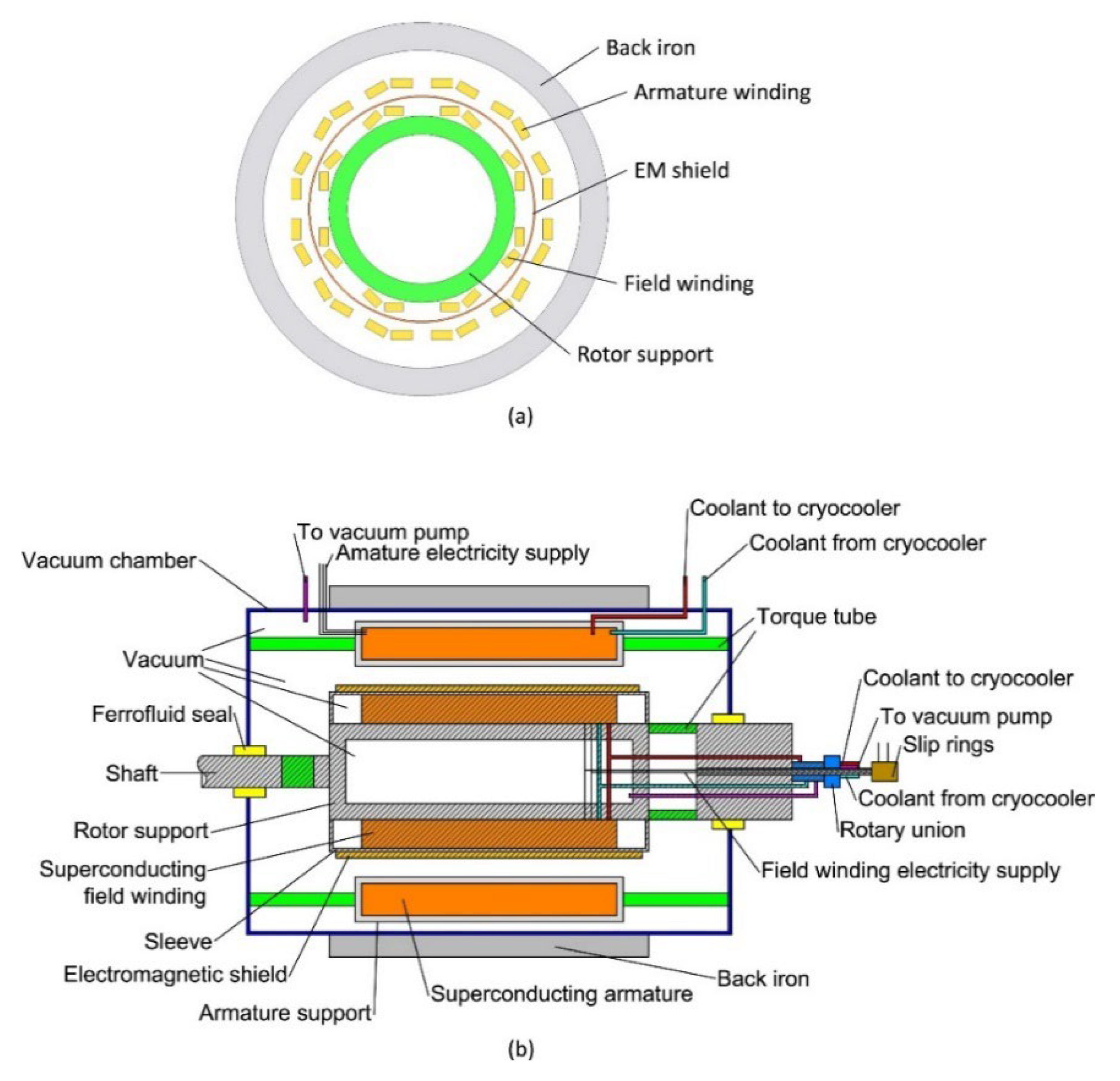
Table 17.
Comparison of High Temperature Superconducting Rotating Electrical Machines [154].
Table 17.
Comparison of High Temperature Superconducting Rotating Electrical Machines [154].
| Types | Working principle | Advantages | Disadvantages | Applications |
|---|---|---|---|---|
| Synchronous motor [156,157,158] | The rotor uses superconducting coils or blocks to generate a direct current magnetic field, while the stator is made of conventional conductors or superconducting materials. | High efficiency, lightweight, high magnetic field, low synchronous reactance | The cooling system is complex, with communication losses, requiring rotational cooling coupling | Wind turbines, ship propulsion, aerospace, industrial motors |
| Induction motor [159,160] | The rotor adopts superconducting squirrel cage bars, and the stator is a conventional conductor; The superconducting material loses its superconducting state during startup and returns to its superconducting state during operation. | High starting torque, low slip operation, high efficiency | In synchronous mode, the rotor magnetic field is limited and precise cooling control is required | Electric vehicles, industrial motors, low-temperature fluid pumps |
| Claw pole motor [161,162,163] | The stator superconducting coil guides the magnetic field through a claw pole structure, and the rotor is made of conventional materials. | Compact structure, non-rotating superconducting components, suitable for high-speed applications | The magnetic field distribution is uneven, and high mechanical strength is required for the claw pole | Aircraft generators, high-power density motors |
| Unipolar motor [164,165,166] | The DC magnetic field is generated by superconducting coils, and the rotor is a conductive disk or offset magnetic pole structure. | High torque, no gear requirements, suitable for low-speed and high-torque scenarios | Sliding contact is prone to wear and requires a liquid metal current collector | Ship propulsion, flywheel energy storage, aerospace high-power generators |
| Magnetic flux modulation motor [167,168,169] | Superconducting blocks or stacked tapes shield or concentrate magnetic fields, and the stator is a conventional conductor. | High power density, low magnetic leakage, and adaptability to complex shapes | Pulse magnetic field pre-magnetization is required, and demagnetization may occur during dynamic operation | Aerospace and high-power-density propulsion systems |
| Hysteresis motor [170,171] | Superconducting bulk rotors generate hysteresis effects in alternating magnetic fields to drive rotation. | Simple structure, no friction loss, suitable for high-speed applications | Hysteresis loss cannot be ignored, resulting in low output power | Micro-motors, specialized equipment for low-temperature environments |
| Fully superconducting motor [172,173,174] | Both the stator and rotor are made of superconducting materials (wires or blocks). | Theoretical efficiency is close to 100%, with a small size and extremely light-weight | High communication loss, complex cooling system, and extremely high cost | Future aviation propulsion and ultra-efficient power generation system |
2.Spherical motor
Ög˘ülmüsß AS et al. [175] designed a novel 3-degree-of-freedom non-integrated rotor permanent magnet spherical motor (NR-PMSM) that separates tilting (X-Y axis) and rotating (Z-axis) motions, simplifying the control algorithm. The main components are shown in Figure 89. The motor adopts a modular design, with a stator arranged in layers and 18 coils (12 inclined coils and 6 rotating coils) for easy assembly and maintenance. The motor is equipped with a multi-ball bearing mechanism, and the rotor is supported by upper and lower cover plates, which reduces friction and improves motion stability without affecting the electromagnetic field. By using ABS material to reduce weight, 24 cubic neodymium magnets are embedded on the rotor surface. The motor is driven by electromagnetic force, and the stator coil is energized to generate a magnetic field, which interacts with the rotor’s permanent magnet. Drive the tilting and rotating motion of the motor by separately controlling the phase and amplitude of the current.
3.Coreless Motor
The outer rotor of the hollow cup permanent magnet motor is equipped with permanent magnets, and the inner and outer rotors rotate synchronously. This structure adopts a coreless cup-shaped stator, which can overcome the iron loss and cogging torque pulsation caused by the iron core and has the advantage of low power consumption [176]. Sun JJ et al. [177] and Zhang L et al. [178] reduced the torque ripple of the motor and further improved the performance of the hollow cup motor through a new design of the inner rotor.
Szelag W et al. [179] proposed a low-cost hollow cup permanent magnet synchronous motor (PMSM) magnetic circuit structure suitable for large-scale production using a 16 pole 12 coil configuration, as shown in Figure 90. The stator of the motor has no iron core and is only composed of copper windings. The rotor adopts a double ferromagnetic ring structure, with radially magnetized permanent magnets attached to the surface. After the stator three-phase winding is energized, a rotating magnetic field is generated, which interacts with the magnetic field of the rotor permanent magnet to drive the rotor to rotate synchronously. Due to the coreless structure, the cogging effect of traditional motors is eliminated, resulting in smoother operation. The dual rotor structure of the motor is combined with sintered neodymium magnets to optimize the magnetic flux path and improve torque density. The first attempt to use injection molded magnets instead of sintered magnets, despite the high cost, provides direction for future process improvements.
4.1.2. Piezoelectric Drive
The basic principle of piezoelectric driving is to utilize the inverse piezoelectric effect of piezoelectric ceramic materials, which means that under the action of an electric field, the piezoelectric material will deform, resulting in mechanical displacement [180]. This effect enables piezoelectric materials to convert between electrical and mechanical energy, generating rotation by controlling their mechanical deformation. Resonant piezoelectric actuators operate in a resonant state and are typically designed in the ultrasonic frequency range; hence, they are also known as ultrasonic motors. Piezoelectric ultrasonic motors (USMs) have received more attention due to their unique qualities compared to traditional magnetic coil-based motors, such as miniaturization, high precision, speed, non-magnetic, silent operation, simple structure, and adaptability [181].
Xu DM et al. [182] proposed a novel rotating ultrasonic motor that only uses longitudinal vibration mode, as shown in Figure 91. The motor consists of two symmetrically arranged longitudinal sensors, a rotor, a base, and an adjustable mounting base. The motor utilizes the longitudinal vibration mode of piezoelectric ceramics to generate frictional force through the longitudinal displacement of the foot driven by sensors, driving the rotor to rotate. Only a single-frequency excitation voltage is required, and directional control can be achieved by adjusting the voltage phase. The relative position between the sensor and the rotor can be adjusted, providing an additional means of adjusting the output characteristics. The dual-sensor synchronous drive enhances the stability of torque output. However, it requires high voltage drive, which may limit low-power applications, and relies on friction transmission. Long-term operation may cause contact surface wear and require regular maintenance.
Shi MH et al. [183] proposed a novel non-contact ultrasonic motor that can generate levitation force and acoustic drive torque, as shown in Figure 92. The motor includes a stator and a rotor. The stator structure is fixed on the mounting plate, and the entire structure is fixed on the support frame. The composition of the stator is shown in Figure 92 (b). The main dimensions of the stator are shown in Figure 92 (c). The high-frequency longitudinal vibration of the motor stator compresses the air film, forming a high-pressure air film, generating axial and radial suspension forces, overcoming the gravity of the rotor, and maintaining stable suspension. The gradual deepening of the design of artificial grooves leads to uneven distribution of gas film pressure in the circumferential direction, forming a pressure gradient, driving the airflow, and generating circumferential shear stress, thereby generating driving torque. The air film completely isolates the stator and rotor, avoiding friction and wear and significantly reducing heat.
Pan QS et al. [184] proposed a resonant piezoelectric rotary motor using a parallel moving gear mechanism, as shown in Figure 93. The piezoelectric transducer generates linear displacement under sinusoidal voltage and synthesizes the planar circular translational motion of the stator through a hinge connection. The stator (internal gear) and rotor (external gear) undergo periodic misalignment meshing due to the difference in tooth count, driving the rotor to decelerate and rotate. By adjusting the phase difference between the excitation voltages of the two transducers, the direction of rotor rotation can be changed. Replacing traditional friction transmission with gear meshing reduces wear and energy loss and improves efficiency. Utilizing the resonance characteristics of vibrators to enhance energy transfer efficiency and support high-power output. By changing the transmission ratio (TR), excitation frequency, and voltage amplitude, the output speed and torque can be flexibly regulated. The motor integrates gear transmission and piezoelectric drive, which can achieve miniaturization and high-power density.
Xun MX et al. [185] proposed a rotary piezoelectric actuator (RPA) based on a spatial spiral compliance mechanism (SSCM). The proposed RPA structure is shown in Figure 94. A single PZT (lead zirconate titanate) stack generates linear displacement through the inverse piezoelectric effect. SSCM converts the linear displacement of the P stack into pure rotational motion. SSCM consists of spiral rods and parallel platforms. The symmetrical layout of the spiral rod counteracts lateral forces and avoids axis deviation. By constraining the design of thrust bearings and bolt connections, the longitudinal degrees of freedom are limited to ensure that the output is a single rotational motion. This actuator can achieve high precision and fast response.
Table 18.
Comparison of piezoelectric rotary motors.
| Types | Advantages | Disadvantages | Applications |
|---|---|---|---|
| Longitudinal vibration mode rotating ultrasonic motor [182] | Simple control, adjustable output characteristics, stable torque, and no magnetic interference | High voltage drive, high power consumption, low output torque, and speed | Optical instrument focusing system, micro robot joint drive, low temperature/vacuum environment |
| Non-contact ultrasonic motor [183] | No contact friction, long lifespan, no wear and heat accumulation, fast operating speed | Low torque may cause failure under high pressure/high load | Medical devices that require silent operation in high-precision cleaning scenarios such as semiconductor manufacturing |
| Gear mesh resonant piezoelectric motor [184] | High efficiency, high power output, flexible speed regulation, and resonance design improve energy efficiency | The adjustment of resonant frequency is complex, and high-frequency vibration may generate noise | Scanning probe microscope for nano-positioning, joint drive for surgical robots, high torque velocimeter in precision manufacturing |
| Space Spiral Flexible Mechanism (SSCM) RPA [185] | High precision and fast response, high motion stability, low cost, no axis offset | Limited output torque, susceptible to material fatigue, sensitive to installation accuracy | Biological microscope, nano-positioning platform and other micro-nano operation scenarios, dynamic vibration compensation system |
The comparison table of different types mentioned above shows that the current research on motor drives presents a trend of technological diversification and performance optimization in parallel, and significant progress has been made in superconducting materials, structural innovation, and breakthroughs in driving modes. Superconducting rotary motors have significantly improved power density and efficiency by applying high-temperature superconducting (HTS) materials. Their lightweight characteristics have outstanding potential in fields such as aviation propulsion and marine power, but complex cooling systems and high costs remain bottlenecks for industrialization. Structural designs such as spherical motors achieve multi-axis motion integration through modular magnetic circuit layout and 3-degree-of-freedom decoupling control, while hollow cup motors eliminate cogging effects with a coreless architecture. Combined with dual rotor magnetic circuit optimization and injection molding magnet process exploration, they balance low loss and manufacturability. The limitations of traditional friction transmission have been overcome in piezoelectric drives. Noncontact ultrasonic motors use air film suspension to achieve zero wear operation, gear mesh piezoelectric motors balance high torque and high efficiency through resonance amplification and phase control, and spatial spiral flexible mechanisms (SSCM) use single piezoelectric stack drive to achieve nanoscale rotational positioning, demonstrating unique advantages in micro-nano operation scenarios. The future development direction will focus on the deep integration of multiple disciplines: superconducting motors need to break through the coupling technology of rotational cooling and low-cost HTS material preparation process. The intelligent driving system will integrate adaptive control algorithms with new materials, such as flexible composite materials and high-temperature-resistant piezoelectric ceramics. The miniaturization and high-power density design rely on additive manufacturing and magnetocaloric synergistic optimization technology. At the same time, the trend towards urbanization promotes innovation in rare earth magnets and energy recovery structures to meet the diversified needs of new energy equipment, precision medical robots, and extreme environmental operation equipment.
4.2. Hydraulic Drive
Hydraulic drive generates force and motion by utilizing liquid to transmit pressure within a closed system, achieving control and operation of mechanical devices [186]. The hydraulic system can carry large loads and achieve precise motion control. It can achieve seamless transmission, smooth transmission, effortless operation, and fast response, and can start at high speed and change direction frequently.
4.2.1. Electro-Hydraulic Servo Drive
Zhu DM et al. [187] designed and validated an integrated electro-hydraulic pump (EHP) based on an axial piston pump, as shown in Figure 95. The electro-hydraulic pump is driven by a brushless DC motor, which generates electromagnetic torque through three-phase back electromotive force to drive the rotor to rotate. The rotor drives the plunger to perform reciprocating motion and adjusts the plunger stroke through the inclined plate and valve plate to achieve periodic oil suction and discharge. The oil is distributed to the high-pressure chamber and low-pressure chamber through the valve plate, and the movement of the plunger produces high-pressure oil output. The motor and pump share the same housing, eliminating the need for a drive shaft, dynamic sealing, and external leaks. Using hydraulic oil to cool the motor eliminates the need for traditional cooling fans and reduces noise and vibration.
Du R et al. [188] proposed a novel energy regenerative hybrid drive system (ERHD), as shown in Figure 96. By integrating the motor, hydraulic, and control modules, the recovery and reuse of braking energy can be achieved and applied to the roll transmission system of reversible rolling mills. During the start-up phase, the electric motor and hydraulic motor jointly drive the load, and the accumulator releases the stored hydraulic energy to assist in acceleration and reduce the load on the electric motor. The electric motor is driven separately in the constant speed stage and the hydraulic module exits. During the braking phase, the hydraulic motor converts the kinetic energy of the load into hydraulic energy and stores it in an accumulator to achieve energy regeneration.
Table 19.
Hydraulic Drive Comparison.
| Types | Advantages | Disadvantages | Applications |
|---|---|---|---|
| Traditional hydraulic drive [186] | High load, precise movement, smooth operation, seamless transmission, and rapid response | Potential leakage risk, high maintenance cost, and loud noise | Scenarios that require high load and precise control |
| Electrohydraulic servo drive [187] | Small size, lightweight, high-power density, low noise, good dispersion performance, high reliability | Insufficient oil absorption during high-speed operation leads to reduced efficiency and vibration | Aircraft hydraulic systems require equipment in environments with sustained high-pressure or low-noise levels |
| Electrohydraulic servo drive [188] | Energy regeneration, reducing the peak power and energy consumption of the motor, and cooling down | The system requires precise control, additional energy storage devices, and pipelines | High inertia frequent start stop scenarios, green and low-carbon industrial applications |
The above comparison table shows that research in the field of hydraulic drive is rapidly developing towards high efficiency, integration, and greening. Although traditional hydraulic drive systems have advantages such as high load, precise control, and fast response, they face inherent defects such as a high risk of leakage and loud noise. In recent years, significant breakthroughs have been made in electro-hydraulic servo-drive technology by integrating electromechanical and hydraulic design. For example, the axial piston electro-hydraulic pump (EHP) adopts a brushless DC motor drive, integrates the motor and pump body structure, eliminates dynamic sealing and external leakage, and uses hydraulic oil to cool the motor, significantly reducing noise and vibration, and improving system compactness and reliability. On the other hand, the newly proposed Energy Regeneration Hybrid Drive System (ERHD) integrates motors, hydraulic modules, and energy storage devices to achieve brake energy recovery and reuse, effectively reducing motor peak power and energy consumption. It is suitable for high inertia frequent start-stop scenarios and reflects the development needs of green and low-carbon industries. In the future, hydraulic drive technology will deeply integrate intelligent control and energy management strategies, further optimize system efficiency and dynamic response, and expand its applications in aerospace, high-precision equipment, and low-carbon industries. At the same time, the oil absorption efficiency under high-speed conditions, the control logic of complex systems, and balancing initial costs and long-term benefits are still urgent challenges that need to be overcome.
4.3. Pneumatic Drive
The pneumatic drive system uses compressed air as the working medium to drive the movement of robots or other machinery through the pressure difference generated by the airflow [189]. The exhaust gas treatment is simple and does not pollute the environment [190]. The system can quickly respond to control signals, achieve automatic control, and is easy to maintain. The startup driver can operate safely in harsh environments such as flammable, explosive, dusty, strong magnetic, radiation, and vibration [191]. The pneumatic drive is widely used in industrial robots, functional equipment of technical systems, transportation systems, and any equipment that executes discrete movements of actuators [192].
4.3.1. Multi Mode Pneumatic Motor
Yang Y et al. [193] designed a multi-mode small pneumatic motor based on a rigid, flexible coupling structure, as shown in Figure 97. Pneumatic motors have continuous rotation and step modes and can quickly switch working modes by adjusting the input air pressure signal. The cylinder stator adopts a circular structure, and the inner wall is fixed with a deformable silicone tube. The rotor consists of rollers, brackets, and pin shafts, and the rollers squeeze the silicone tube to generate thrust. When compressed air is input, the silicone tube expands and deforms locally, pushing the roller to rotate. Multiple ports supply gas simultaneously in continuous mode, and the roller continuously pushes the silicone tube to achieve high-speed rotation. In step mode, pulse air pressure is sequentially inputted to a single port, and the roller is gradually moved to achieve a fixed step angle. However, the accuracy of the motor is affected by the elastic deformation and inertia of the silicone tube in step mode. The output torque of the step mode is lower than that of the continuous mode, and the lifespan and pressure resistance of the silicone tube limit its long-term high-pressure application.
4.3.2. Pneumatic Artificial Muscles
Stoll JT et al. [194] proposed a rotational drive unit that combines compliance and high precision by combining pneumatic artificial muscles (PAMs) with inclined plate structures, as shown in Figure 98. The linear contraction force of PAMs is converted into rotational torque through the inclined plate structure, and the normal force is transmitted through the four pivot bearings, avoiding the stick-slip phenomenon of traditional aerodynamics. By independently adjusting the pressure of each PAM and controlling the total torque and system stiffness, high-precision positioning and flexible motion can be achieved. Dynamic adjustment of system stiffness is achieved through pressure regulation to adapt to different load requirements. A 16-bit encoder and proportional valve control are used to achieve fine motion. However, the rotary drive unit has a large volume and weight, requiring lightweight improvements and independent control of multiple proportional valves. The system is complex and costly, with a maximum pressure limit of 600 kPa, which may limit torque output.
Table 20.
Comparison of Pneumatic Drive.
| Types | Advantages | Disadvantages | Applications |
|---|---|---|---|
| Traditional pneumatic drive [189,190,191,192] | Environmental protection, strong adaptability, fast response, easy to automatically control | Low torque, accuracy affected by pressure fluctuations and elastic components, high noise | Industrial robots and automation scenarios in harsh environments |
| Multi-mode pneumatic motor [193] | Supports continuous rotation and step mode switching, with good output performance and low-cost | Accuracy is affected by the elastic deformation and inertia of silicone tubing | Light load scenarios of pipeline robots, modular robotic arms, and fast mode switching |
| Pneumatic artificial muscles [194] | Flexibility and high precision, no stick-slip phenomenon, high-precision positioning | The maximum pressure limit restricts the torque output | Flexible robot joints, precision assembly, medical equipment |
The above comparison table shows that the current pneumatic drive technology has demonstrated unique advantages in harsh working conditions and flexible robot fields due to its environmental friendliness, adaptability, and fast response capability. Traditional pneumatic drives use air as the medium and have the characteristics of simple structure, convenient maintenance, and no pollution. However, they have limitations such as low output torque, accuracy affected by pressure fluctuations, and high noise. In recent years, research has focused on improving accuracy, expanding functionality, and enhancing adaptability, such as the newly proposed multi-mode pneumatic motor, which achieves continuous rotation and step mode switching through a rigid-flexible coupling structure, balancing low cost and high dynamic performance. However, its step accuracy is limited by the elastic deformation of silicone tubing, and its durability in high-pressure scenarios needs to be improved. Combining pneumatic artificial muscles (PAMs) with a rotating drive unit of inclined plate structure, high-precision positioning, and dynamic stiffness adjustment are achieved through independent pressure regulation, avoiding the stick-slip phenomenon of traditional pneumatic systems. However, the system is highly complex, has a large volume and weight, and the maximum pressure limit affects torque output. In the future, pneumatic drives will deepen towards intelligence, lightweight, and high energy efficiency, integrating intelligent sensing and adaptive control algorithms to improve dynamic accuracy, developing new composite materials to enhance actuators’ pressure resistance and lifespan, and optimizing integrated design to reduce system volume and cost. Meanwhile, how to break through torque limitations, balance environmental adaptability and control complexity while maintaining flexibility, and expand its applications in high-end scenarios such as medical and precision assembly remains a key research direction.
5. Conclusions and Future Research Direction
5.1. Conclusions
This article comprehensively reviews the research status of rotary motion mechanisms and their drive systems. Traditional mechanisms such as spur gears and helical gears dominate inefficient transmission but face challenges of noise and wear. New mechanisms such as non-circular and magnetic gears have achieved variable speed transmission and contactless driving through structural innovation, significantly improving dynamic performance. The drive belt and sprocket mechanism performs excellently in long-distance transmission, while the cam and linkage mechanisms are indispensable in high-precision motion control. Regarding bearing technology, air static pressure bearings and magnetic levitation bearings have demonstrated unique advantages in high-speed and low-friction scenarios. New mechanisms such as spherical gears and multi-link planetary transmissions have expanded their application scope through biomimetic design and modular integration. In the drive system, the efficiency of the electric drive, the hydraulic drive’s high load capacity, and the pneumatic drive’s environmental adaptability are all emphasized. Future performance breakthroughs need to be achieved by combining intelligent control. Overall, material innovation, topology optimization, and interdisciplinary collaboration are key paths to improving the comprehensive performance of rotating mechanisms.
5.2. Future Research Direction
Future research on rotational motion mechanisms can be explored in depth from the following directions:
(1) Develop high-strength composite materials, superconducting materials, and self-healing coatings to reduce wear and extend lifespan; Utilize additive manufacturing to achieve integrated molding of complex mechanisms.
(2) Integrating sensors and real-time control algorithms to achieve online monitoring and adaptive adjustment of dynamic characteristics of mechanisms such as variable stiffness joints and intelligent lubrication systems.
(3) Combining piezoelectric effect and magnetic levitation energy recovery technology to reduce energy loss during transmission and promote green manufacturing.
(4) Drawing inspiration from biological motion mechanisms, design biomimetic spherical joints and flexible multi-link mechanisms to enhance motion flexibility in complex environments.
(5) By combining artificial intelligence, topology optimization, and multi-physics field simulation, we aim to break through the design limitations of traditional mechanisms and promote the development of rotary motion systems towards high efficiency, compactness, and intelligence.
This article provides a theoretical framework for the innovation of rotary motion mechanisms, which needs to be further validated through experiments and engineering applications in the future to promote their practical application in high-end equipment and robotics fields.
Author Contributions
Xuecheng Luan was responsible for the conception and design, acquisition of data, analysis, and interpretation of data, drafting of the initial manuscript, and critically revising it for important intellectual content. Hanwen Yu proposed a research topic and was responsible for the numerical analysis of the manuscript and provided valuable suggestions for the manuscript. Yandong Liu was responsible for designing the conception, interpreting data, and reviewing all manuscript drafts. Mingxuan He and Jinglei Zhou collected data and images, completed the follow-up information, and wrote a draft. Chunxiao Ding and Ying Zhang were responsible for conception and design, and reviewing all manuscript drafts.
Funding
This research was funded by the Natural Science Foundation of Shandong Province (No. ZR2024QE358) and the Doctoral Research Fund Project of Shandong Jianzhu University (Grant No. X21030Z).
Institutional Review Board Statement
Not applicable.
Informed Consent Statement
Not applicable.
Data Availability Statement
The original contributions presented in the study are included in the article, further inquiries can be directed to the corresponding author.
Conflicts of Interest
The authors declare no conflicts of interest.
References
- Huang, K.L.; Yang, Y.X.; Liu, Y.; Zhong, Y.P. Haitao Ren Study on rock breaking mechanism of PDC bit with rotating module. Journal of Petroleum Science and Engineering 2020, 192, 107312. [Google Scholar] [CrossRef]
- Zhu, Y.; Li, G.P.; Tang, S.N.; Wang, R.; Su, H.; Wang, C. Acoustic signal-based fault detection of hydraulic piston pump using a particle swarm optimization enhancement CNN. Applied acoustics 2022, 192, 108718. [Google Scholar] [CrossRef]
- Chao, Q.; Zhang, J.; Xu, B.; Wang, Q.N.; Lyu, F.; Li, K. Integrated slipper retainer mechanism to eliminate slipper wear in high-speed axial piston pumps. Frontiers of Mechanical Engineering 2022, 17, 1. [Google Scholar] [CrossRef]
- Myszka, D.H.; Joo, J.J.; Murray, A.P. A Multi-Objective Mechanism Optimization for Controlling an Aircraft Using a Bio-Inspired Rotating Empennage. Journal of Mechanisms and Robotics 2022, 14(4), 045003. [Google Scholar] [CrossRef]
- Jia, X.Y.; Zhang, X. Numerical Study on Local Entropy Production Mechanism of a Contra-Rotating Fan. Entropy 2023, 25(9), 1293. [Google Scholar] [CrossRef] [PubMed]
- Satake, Y.; Takanishi, A.; Ishii, H. Novel growing robot with inflatable structure and heat-welding rotation mechanism. IEEE/ASME Transactions on Mechatronics 2020, 25, 1869–1877. [Google Scholar] [CrossRef]
- Bortnowski, P.; Gładysiewicz, A.; Gładysiewicz, L.; Król, R.; Ozdoba, M. Conveyor Intermediate TT Drive with Power Transmission at the Return Belt. Energies 2022, 15(16), 6062. [Google Scholar] [CrossRef]
- Kumaran, V.U.; Weiss, L.; Zogg, M.; Wegener, K. Analytical flat belt drive model considering bilinear elastic behaviour with residual strains. Mechanism and Machine Theory 2023, 190, 105466. [Google Scholar] [CrossRef]
- Ren, F.C.; Liang, X.; Jiang, T. Performance analysis of escalator drive chain plate used for 5 years. In 2020 5th International Conference on Mechanical, Control and Computer Engineering (ICMCCE). IEEE 2020, 788-791.
- Jiang, S.; Huang, S.; Zeng, Q.; Chen, S.J.; Lv, J.W.; Zhang, Y.Q.; Qu, W. Dynamic characteristics of the chain drive system under multiple working conditions. Machines 2023, 11(8), 819. [Google Scholar] [CrossRef]
- Li, L.Q.; Zhang, D.; Tian, C.X. A family of generalized single-loop RCM parallel mechanisms: structure synthesis, kinematic model, and case study. Mechanism and Machine Theory 2024, 195. [Google Scholar] [CrossRef]
- Xu, B.; Yang, Y.; Yan, Y.; Zhang, B. Bionics design and dynamics analysis of space webs based on spider predation. Acta Astronautica 2019, 159, 294–307. [Google Scholar] [CrossRef]
- Xu, B.; Yang, Y.; Zhang, B.; Yan, Y.; Yi, Z.Y. Bionic design and experimental study for the space flexible webs capture system. IEEE Access 2020, 8, 45411–45420. [Google Scholar] [CrossRef]
- Wang, G.; Liu, K.; Ma, X.; Chen, X.; Hu, S.H.; Tang, Q.Y.; Liu, Z.J.; Ding, M.X.; Han, S. J. Optimal design and implementation of an amphibious bionic legged robot. Ocean Engineering 2023, 272, 113823. [Google Scholar] [CrossRef]
- Zhu, Y.G.; Li, R.Y.; Song, Z.P. Bionic muscle control with adaptive stiffness for bionic parallel mechanism. Journal of Bionic Engineering 2023, 20(2), 598–611. [Google Scholar] [CrossRef]
- Wang, Z.; Ge, W.J.; Zhang, Y.H.; Liu, B.; Liu, B.; Jin, S.K.; Li, Y.Z. Optimization Design and Performance Analysis of a Bionic Knee Joint Based on the Geared Five-Bar Mechanism. Bioengineering 2023, 10(5), 582. [Google Scholar] [CrossRef]
- Tang, S.N.; Zhu, Y.; Yuan, S.Q. Bionics-Inspired Structure Boosts Drag and Noise Reduction of Rotating Machinery. Journal of Bionic Engineering 2023, 20(6), 2797–2813. [Google Scholar] [CrossRef]
- Aalders, J.W.G.; Wildeman, K.J.; Ploeger, G.R.; van der Meij, Z.N. New developments with the cryogenic grating drive mechanisms for the ISO spectrometers. Cryogenics 1989, 29(5), 550–552. [Google Scholar] [CrossRef]
- Guo, P.; Noji, H.; Yengo, C.M.; Zhao, Z.Y.; Grainge, I. Biological nanomotors with a revolution, linear, or rotation motion mechanism. Microbiology and Molecular Biology Reviews 2016, 80(1), 161–186. [Google Scholar] [CrossRef]
- Watanabe, M.; Tadakuma, K.; Konyo, M.; Tadokoro, S. Bundled rotary helix drive mechanism capable of smooth peristaltic movement. IEEE Robotics and Automation Letters 2020, 5(4), 5537–5544. [Google Scholar] [CrossRef]
- An, D.W.; Huang, W.Q.; Liu, W.Q.; Xiao, JR.; Liu, X.C.; Liang, Z.W. Meshing drive mechanism of double traveling waves for rotary piezoelectric motors. Mathematics 2021, 9, 445. [Google Scholar] [CrossRef]
- Koc, B.; Kist, S.; Hamada, A. Wireless Piezoelectric Motor Drive. Actuators 2023, 12(4), 136. [Google Scholar] [CrossRef]
- Wang, B.Y.; Liang, Y.; Xu, D.Z.; Wang, Z.H.; Ji, J. Design on electrohydraulic servo driving system with walking assisting control for lower limb exoskeleton robot. International Journal of Advanced Robotic Systems 2021, 18(1), 1729881421992286. [Google Scholar] [CrossRef]
- Milecki, A.; Jakubowski, A.; Kubacki, A. Design and Control of a Linear Rotary Electro-Hydraulic Servo Drive Unit. Applied Sciences 2023, 13(15), 8598. [Google Scholar] [CrossRef]
- Habermehl,C. ;Jacobs,G.; Neumann, S. A modeling method for gear transmission efficiency in transient operating conditions. Mechanism and Machine Theory 2020, 153, 103996. [Google Scholar] [CrossRef]
- Karpov, O.; Nosko, P.; Fil, P.; Nosko, O.; Olofsson, U. Prevention of resonance oscillations in gear mechanisms using non-circular gears. Mechanism and Machine Theory 2017, 114, 1–10. [Google Scholar] [CrossRef]
- Ristivojević, M.; Lučanin, V.; Dimić, A.; Mišković, Z.; Burzić, A.; Stamenić, Z.; Rackov, M. Investigation of the heavy duty truck gear drive failure. Engineering Failure Analysis 2023, 144, 106995. [Google Scholar] [CrossRef]
- Baidu.https://baike.baidu.com/item/%E9%BD%BF%E8%BD%AE%E6%9C%BA%E6%9E%84/10448252?fr=ge_ala, December 5, 2024.
- Chen, Z.Y.; Guo, Z.H.; Fang, B.; Gao, L.Y.; Su, G.S.; Liu, B.Q. Simulation study of the punching forming process and die wear of spur gears. The International Journal of Advanced Manufacturing Technology 2024, 131(9), 4635–4648. [Google Scholar] [CrossRef]
- Pedrero, J.I.; Sánchez, M.B.; Pleguezuelos, M. Analytical model of meshing stiffness, load sharing, and transmission error for internal spur gears with profile modification. Mechanism and Machine Theory 2024, 197, 105650. [Google Scholar] [CrossRef]
- Yang, X.; Lei, Y.G.; Liu, H.; Yang, B.; Li, X.; Li, N.P. Rigid-flexible coupled modeling of compound multistage gear system considering flexibility of shaft and gear elastic deformation. Mechanical Systems and Signal Processing 2023, 200, 110632. [Google Scholar] [CrossRef]
- Shang, J.; Zhang, X.F.; Zhou, J.X.; Wang, H.W.; Liu, Y. Analysis of dynamic load characteristics of high coincidence spur gears. Combination Machine Tool and Automation Processing Technology 2024, (09), 76-80+85.
- Achari, A.S.; Daivagna, U.M.; Banakar, P.; Algur, V. Effect of Addendum Modification on Helix Angle in Involute Helical Gear Pairs with Long-Short Addendum System Focusing on Specific Sliding. Journal of The Institution of Engineers (India): Series C 2024, 1–13. [Google Scholar] [CrossRef]
- Rajesh, S.; Marimuthu, P.; Dinesh Babu, P.; Venkatraman, R. Contact fatigue life estimation for asymmetric helical gear drives. International Journal of Fatigue 2022, 164. [Google Scholar] [CrossRef]
- Wei, J.; Gao, P.; Hu, X.L.; Sun, W.; Zeng, J. Effects of dynamic transmission errors and vibration stability in helical gears. Journal of mechanical science and technology 2014, 28, 2253–2262. [Google Scholar] [CrossRef]
- Andreas, H.Z.; Sascha, W.; Konrad, W. Face-gear drive: Meshing efficiency assessment. Mechanism and Machine Theory 2022, 171. [Google Scholar]
- Lin, C.; Wu, X.Y. Calculation and analysis of contact ratio of helical curve-face gear pair. Journal of the Brazilian Society of Mechanical Sciences and Engineering 2017, 39, 2269–2278. [Google Scholar] [CrossRef]
- Zschippang, H.A.; Weikert, S.; Wegener, K. Face-gear drive: Meshing efficiency assessment. Mechanism and Machine Theory 2022, 171, 104765. [Google Scholar] [CrossRef]
- Rai, P.; Barman, A.G. Design optimization of worm gear drive with reduced power loss. In IOP Conference Series: Materials Science and Engineering. IOP Publishing 2019, 635(1), 012015.
- Deng, X.Q.; Wang, S.S.; Hammi, Y.; Qian, L.M.; Liu, Y.C. A combined experimental and computational study of lubrication mechanism of high precision reducer adopting a worm gear drive with complicated space surface contact. Tribology International 2020, 146, 106261. [Google Scholar] [CrossRef]
- Litvin, F.L.; Nava, A.; Fan, Q. Fuentes, A. New geometry of face worm gear drives with conical and cylindrical worms: generation, simulation of meshing, and stress analysis. Computer methods in applied mechanics and engineering 2002, 191, 3035–3054. [Google Scholar] [CrossRef]
- Meng, Q.X.; Zhao, Y.P.; Cui, J.; Mu, S.B.; Li, G.F.; Chen, X.Y. Kinematics of point-conjugate tooth surface couple and its application in mixed mismatched conical worm drive. Mechanism and Machine Theory 2022, 167, 104528. [Google Scholar] [CrossRef]
- Rahmani, M.; Redkar, S. Optimal DMD Koopman Data-Driven Control of a Worm Robot. Biomimetics 2024, 9(11), 666. [Google Scholar] [CrossRef]
- Abrahám, R.; Majdan, R.; Kollárová, K.; Tkáč, Z.; Matejková, E.; Masarovičová, S.; Drlička, R. Spike Device with Worm Gear Unit for Driving Wheels to Improve the Traction Performance of Compact Tractors on Grass Plots. Agriculture 2024, 14(4), 545. [Google Scholar] [CrossRef]
- Liu, F.; Chen, Y.H.; Lu, B.B.; Luo, W.J.; Chen, B.K. Study on the vibration characteristics of worm helical gear drive. Mechanism and Machine Theory 2024, 191. [Google Scholar] [CrossRef]
- Zhang, X.C.; Nie, J.H. Dual lead linear contact biased worm driveⅠ- principle analysis. Journal of Beijing Institute of Technology 2011, 37(02), 161–166. [Google Scholar]
- Mu, S.B.; Zhao, Y.P.; Cui, J.; Meng, Q.X.; Li, H.F. Meshing theory of face worm gear drive with hardened cylindrical worm. Mechanism and Machine Theory 2023, 185, 105323. [Google Scholar] [CrossRef]
- Zhuang, W.H.; Hua, L.; Han, X.H.; Zheng, F.Y. Design and hot forging manufacturing of non-circular spur bevel gear. International Journal of Mechanical Sciences 2017, 133129–146. [Google Scholar] [CrossRef]
- Nie, S.W.; Chen, J.Y.; Han, Z.Y. Tooth surface mismatch design of cycloidal bevel gear based on two directions modification of pinion cutter. In Journal of Advanced Mechanical Design, Systems, and Manufacturing 2024,18(2), JAMDSM0024-JAMDSM0024.
- Gonzalez-Perez, I.; Fuentes-Aznar, A. An exact system of generation for face-hobbed hypoid gears: Application to high reduction hypoid gear drives. Mechanism and Machine Theory 2023, 179, 105115. [Google Scholar] [CrossRef]
- Wang, S.; Yang, J.J.; Li B, Zhao, J. W.; Wang, B.; Xin, W.; Cheng, B. Lapping adjustment method for actual surface of hypoid gears. Journal of the Brazilian Society of Mechanical Sciences and Engineering 2023, 45(2), 122. [Google Scholar] [CrossRef]
- Liang, G.Q.; Zong, L.J.; Lam, T.L. DISG: driving-integrated spherical gear enables singularity-free full-range joint motion. IEEE Transactions on Robotics 2023, 39(6), 4464–4481. [Google Scholar] [CrossRef]
- Tanaka, T.; Oiwa, T.; Kotani, A. Proposal for a Multiple-DOF Spherical Gear and Investigation of Backlash and Transmitted Efficiency Between Gears. International Journal of Precision Engineering and Manufacturing 2021, 22, 1897–1908. [Google Scholar] [CrossRef]
- Zheng, F.Y.; Hua, L.; Han, X.H.; Li, B.; Chen, D.F. Synthesis of indexing mechanisms with non-circular gears. Mechanism and Machine Theory 2016, 105, 108–128. [Google Scholar] [CrossRef]
- Mundo, D. Geometric design of a planetary gear train with non-circular gears. Mechanism and machine theory 2006, 41(4), 456–472. [Google Scholar] [CrossRef]
- Yu, G.H.; Yu, J.P.; Tong, J.H.; Ye, B.L.; Zheng, S.Y. Design of a Conjugated Concave convex Non circular Gear Mechanism. China Mechanical Engineering 2016, 27 (16), 2155-2159+2165.
- Chen, Y.Z.; Xiao, X.P.; Zhang, D.P.; Xiao, H.F.; Lyu, Y.L. Design method of a novel variable speed ratio line gear mechanism. Proceedings of the Institution of Mechanical Engineers, Part C: Journal of Mechanical Engineering Science 2021, 235(6),1071-1084.
- Ding, J.; Liu, L.W.; Wei, Y.T.; Deng, A.P. Improved design method for line gear pair based on screw theory. Journal of Mechanical Science and Technology 2022, 36(4), 1867–1878. [Google Scholar] [CrossRef]
- Chen, Z.; Ding, H.F.; Zeng, M. Nonrelative sliding gear mechanism based on function-oriented design of meshing line functions for parallel axes transmission. Advances in Mechanical Engineering 2018, 10(9), 1687814018796327. [Google Scholar] [CrossRef]
- Shin, J.H.; Kim, C.H.; Yun, P.H.; Kwon, S.M. Dual cycloid gear mechanism for automobile safety pretensioners. Journal of Central South University 2012, 19, 365–373. [Google Scholar] [CrossRef]
- Wu, Y.C.; Chan, C.T. Development of magnetic gear mechanisms. Transactions of the Canadian Society for Mechanical Engineering 2017, 41(5), 758–770. [Google Scholar] [CrossRef]
- Yin, X.; Fang, Y.; Pfister, P.D. A novel single-PM-array magnetic gear with HTS bulks. IEEE Transactions on Applied Superconductivity 2017, 27(4), 1–5. [Google Scholar] [CrossRef]
- Jing, L.B.; Gong, J.; Huang, Z.X.; Ben, T.; Huang, Y.H. A new structure for the magnetic gear. IEEE Access 2019, 7, 75550–75555. [Google Scholar] [CrossRef]
- Campbell, A.M. A superconducting magnetic gear. Superconductor Science and Technology 2016, 29(5), 054008. [Google Scholar] [CrossRef]
- Dong, K.; Yu, H.T.; Hu, M.Q. Study of an axial-flux modulated superconducting magnetic gear. IEEE Transactions on Applied Superconductivity 2018, 29(2), 1–5. [Google Scholar] [CrossRef]
- Gao, S.; Zhang, R.C.; Wu, F.; Luo, J.; Pu, H.Y.; Chu, F.L.; Han, Q.K. Rotating single-electrode triboelectric V-belts with skidding and wear monitoring capabilities. Tribology International 2024, 193, 109404. [Google Scholar] [CrossRef]
- Kumaran, V.U.; Weiss, L.; Zogg, M.; Wegener, K. Analytical flat belt drive model considering bilinear elastic behaviour with residual strains. Mechanism and Machine Theory 2023, 190, 105466. [Google Scholar] [CrossRef]
- Feng, X.; Shangguan, W.B.; Deng, J.X.; Jing, X.J. Modeling and dynamic analysis of accessory drive systems with integrated starter generator for micro-hybrid vehicles. Proceedings of the Institution of Mechanical Engineers, Part D: Journal of Automobile Engineering 2019, 233(5), 1162-1177.
- Long, S.B.; Zhao, X.Z.; Shangguan, W.B.; Zhu, W.D. Modeling and validation of dynamic performances of timing belt driving systems. Mechanical Systems and Signal Processing 2020, 144, 106910. [Google Scholar] [CrossRef]
- Ruan, S.H.; Gao, S.; Feng, J.G.; Kong, Y.; Han, Q.K.; Chu, F.L. Intelligent triboelectric V-belts with condition monitoring capability. Mechanical Systems and Signal Processing 2024, 209, 111132. [Google Scholar] [CrossRef]
- Chen, J.N.; Ye, J.; Wang, Y.; Sun, X.C.; Xia, X.D.; He, X.J. Design, modeling and experiment of a novel synchronous belt drive with noncircular pulleys. Iranian Journal of Science and Technology. Transactions of Mechanical Engineering 2020, 44, 533–542. [Google Scholar]
- Saito, R.; Noda, N.A.; Sano, Y.; Song, J.; Minami, T.; Birou, Y.; Miyagi, A.; Huang, Y.S. Fatigue strength analysis and fatigue damage evaluation of roller chain. Metals 2018, 8(10), 847. [Google Scholar] [CrossRef]
- Lanaspeze, G.; Guilbert, B.; Manin, L.; Ville, F. Quasi-Static Chain Drive Model for Efficiency Calculation-Application to Track Cycling. Mechanism and Machine Theory 2024, 2024. 203, 105780. [Google Scholar] [CrossRef]
- Cheng, W.J.; Chi, C.Z.; Wang, Y.Z.; Lin, P.; Zhao, R.H.; Liang, W. 3D FEM simulation of flow velocity field for 5052 aluminum alloy multi-row sprocket in cold semi-precision forging process. Transactions of Nonferrous Metals Society of China 2015, 25(3), 926–935. [Google Scholar] [CrossRef]
- Yang, J.X.; Feng, Z.M.; Wang, X.G. Oil injection lubrication analysis of a silent chain drive system. Advances in Engineering Software 2022, 172, 103210. [Google Scholar] [CrossRef]
- Cheng, Y.B.; Chen, L.X.; Ge, PY.; Chen, X.M.; Niu, J.X. Design and optimization of dual-phase chain transmission system based on single tooth chain plate. Mechanics Based Design of Structures and Machines 2023, 51(2), 899–913. [Google Scholar] [CrossRef]
- Krithikaa, D.; Chandramohan, P.; Suresh, G.; Rathinasabapathi, G.; Madheswaran, D.K.; Mohammed Faisal, A. A study on: Design and fabrication of E-glass fiber reinforced IPN composite chain plates for low duty chain drives. Materials Today: Proceedings, 2024.
- Tiboni, M.; Amici, C.; Bussola, R. Cam Mechanisms Reverse Engineering Based on Evolutionary Algorithms. Electronics 2021, 10(24), 3073. [Google Scholar] [CrossRef]
- Miiller, M.; Hoffmann, M.; Hiising, M.; Corves, B. Using servo-drives to optimize the transmission angle of cam mechanisms. Mech. Mach. Theory 2019, 137, 165–175. [Google Scholar] [CrossRef]
- Baidu.https://baike.baidu.com/item/%E5%87%B8%E8%BD%AE%E6%BB%9A%E5%AD%90/9971479?fr=ge_ala,(September 22, 2024).
- Yan, H.S.; Chen, H.H. Geometry design and machining of roller gear cams with cylindrical rollers. Mechanism and Machine Theory 1994, 29(6),803-812.
- Yousuf, L.S.; Marghitu, D.B. Analytic and numerical results of a disc cam bending with a roller follower. SN Applied Sciences 2020, 2, 2,1–15. [Google Scholar] [CrossRef]
- Chang, W.T.; Hu, Y. E. An integrally formed design for the rotational balancing of disk cams. Mechanism and Machine Theory 2021, 161, 104282. [Google Scholar] [CrossRef]
- Chang, W.T.; Hu, Y.E.; Chang W, C. An improved design for rotating balance of assembled type conjugate disk cams. Mechanism and Machine Theory 2022, 171, 104700. [Google Scholar] [CrossRef]
- Tsay, D.M.; Lin, B.J. Profile determination of planar and spatial cams with cylindrical roller-followers. Proceedings of the Institution of Mechanical Engineers, Part C: Journal of Mechanical Engineering Science 1996, 210(6), 565-574.
- Kamali, S.H.; Miri, M.H.; Moallem, M.; Arzanpour, S. Cylindrical cam electromagnetic vibration damper utilizing negative shunt resistance. IEEE/ASME Transactions on Mechatronics 2019, 25(2), 996-1004.
- Sakhaei, A.H.; Kaijima, S.; Lee, T.L.; Tan, Y.Y.; Dunn, M.L. Design and investigation of a multi-material compliant ratchet-like mechanism. Mechanism and Machine Theory 2018, 121, 184–197. [Google Scholar] [CrossRef]
- Hao, Y.; Yuan, W.; Zhang, H.; Kang, H.; Chang, H. A rotary microgripper with locking function via a ratchet mechanism. Journal of Micromechanics and Microengineering 2015, 26(1), 015008. [Google Scholar] [CrossRef]
- Pham, P.H.; Dang, L.B.; Nguyen, D.T.; Nguyen, D.Q. A micro transmission system based on combination of micro elastic structures and ratchet mechanism. Microsystem Technologies 2017, 23, 381–387. [Google Scholar] [CrossRef]
- Roach, G.M. An investigation of compliant over-running ratchet and pawl clutches. Brigham Young University, America 2003.
- Bondaletov, V.P. Ratchet mechanisms for high-speed transmissions. Russian Engineering Research 2008, 28(9), 845–848. [Google Scholar] [CrossRef]
- Rizescu, C.I.; Baciu, D.E.; Rizescu, D. Study behaviour of ratchet mechanism manufactured with 3D printing technology. In IOP Conference Series: Materials Science and Engineering. IOP Publishing 2022, 1235(1), 012001.
- Khare, A.K.; Dave, R. K. Optimizing 4-bar crank-rocker mechanism. Mechanism and Machine Theory 1979, 14(5), 319–325. [Google Scholar] [CrossRef]
- Barker, C.R. A complete classification of planar four-bar linkages. Mechanism and Machine Theory 1985, 20, 535–554. [Google Scholar] [CrossRef]
- Mohammed, S.E.; Baharom, M.B.; Aziz, A.R.A.; Zainal A, E.Z. Modelling of combustion characteristics of a single curved-cylinder spark-ignition crank-rocker engine. Energies 2019, 12(17), 3313. [Google Scholar] [CrossRef]
- Sahin, D.E. Dynamic Design of Crank-Rocker SI Engine Mechanism. Journal of Vibration Engineering & Technologies 2022, 10(7), 2853-2875.
- Sapietová, A.; Štalmach, O.; Sapieta, M. Synthesis and sensitivity analysis of the crank-rocker mechanism. In IOP Conference Series: Materials Science and Engineering. IOP Publishing 2020, 776(1), 012060.
- Conn, A.T.; Burgess, S.C.; Ling, C.S. Design of a parallel crank-rocker flapping mechanism for insect-inspired micro air vehicles. Proceedings of the Institution of Mechanical Engineers. Part C: Journal of Mechanical Engineering Science 2007, 221(10), 1211-1222.
- Mutlu, H. Design of the crank–rocker mechanism for various design cases based on the closed-form solution. Sādhanā 2021, 46(1),4.
- Joshi, R.; Arakeri, J. Long-distance sinusoidal actuation in self-propelling apparatus: a novel spiral spring-based crank rocker mechanism. Sādhanā 2024, 49(1), 16.
- Tuan, D.A. Application of the double crank mechanism in designing complex-stroke press. Journal of Military Science and Technology 2023, (FEE), (FEE),149–156. [Google Scholar] [CrossRef]
- Li, B.Y. Simulation and Optimization of Double crank 2K-H Wheel System Reversing Device for Pumping Unit. Master’s thesis. Yanshan University. Qinhuangdao City, Hebei Province, China. June 2022.
- Radaelli, G. Reverse-twisting of helicoidal shells to obtain neutrally stable linkage mechanisms. International Journal of Mechanical Sciences 2021, 202, 106532. [Google Scholar] [CrossRef]
- Liu, W.Q.; Chen, Y. A double spherical 6R linkage with spatial crank-rocker characteristics inspired by kirigami. Mechanism and Machine Theory 2020, 153, 103995. [Google Scholar] [CrossRef]
- Michalec, M.; Svoboda, P.; Křupka, I.; Hartl, M. A review of the design and optimization of large-scale hydrostatic bearing systems. Engineering Science and Technology, an International Journal 2021, 24(4), 936-958.
- Miettinen, M.; Vainio, V.; Theska, R.; Viitala, R. Aerostatically sealed chamber as a robust aerostatic bearing. Tribology International 2022, 173, 107614. [Google Scholar] [CrossRef]
- Laldingliana, J.; Debnath, S.; Biswas, P.K.; Das, U. Design and speed control of U-type 3-coil active magnetic bearing. Electrical Engineering 2024, 106(2), 1135–1145. [Google Scholar] [CrossRef]
- Su, B.; Lu, C.H.; Li, C.H. Current Status of Research on Hybrid Ceramic Ball Bearings. Machines 2024, 12(8), 510. [Google Scholar] [CrossRef]
- Chen, F.; Yan, K.; Zhang, X.H.; Zhu, Y.S.; Hong, J. Microscale simulation method for prediction of mechanical properties and composition design of multilayer graphene-reinforced ceramic bearings. Ceramics International 2021, 47(12), 17531–17539. [Google Scholar] [CrossRef]
- Zhang, K.; Gao, L.W.; Wang, Z.; Wang, Z.N.; Zhang, L.Q. Nonlinear dynamic analysis of ceramic bearing rotor system considering temperature variation fit clearance. Journal of the Brazilian Society of Mechanical Sciences and Engineering 2024, 46(5), 265. [Google Scholar] [CrossRef]
- An, D.; Wei, Y.J.; Kumar, A.; Ma, S.J.; Shao, M.; Zheng, H.; Wang, Y.H.; Xu, P.K. Dynamic analysis of full-ceramic bearing-rotor system under thermally induced loosening in aerospace applications. Engineering Failure Analysis 2024, 159, 108080. [Google Scholar] [CrossRef]
- Lin, W.Y.; Tsai, Y.H.; Hsiao, K.M. A new indexing motion program for optimum designs of Geneva mechanisms with curved slots. Proceedings of the Institution of Mechanical Engineers, Part C: Journal of Mechanical Engineering Science 2017, 231(21), 3974-3986.
- Pasika, V.; Nosko, P.; Nosko, O.; Bashta, O.; Heletiy, V.; Melnyk, V. A method to synthesise groove cam Geneva mechanisms with increased dwell period. Proceedings of the Institution of Mechanical Engineers, Part C: Journal of Mechanical Engineering Science 2024, 238(15), 7544-7555.
- Yang, Y.H.; Xie, R.; Wang, J.Y.; Tao, S.Y. Design of a novel coaxial cam-linkage indexing mechanism. Mechanism and Machine Theory 2022, 169, 104681. [Google Scholar] [CrossRef]
- Douyin. https://v.douyin.com/iyC7S1tV/, September 6, 2024.
- Bilibili.https://www.bilibili.com/video/BV1DFWxeGEXn/?spm_id_from=333.999.0.0&vd_source=a4b7c6e62117d66b6d9389ffbd501cca, August 21, 2024.
- Yang, Y.Q.; Chen, P.H.; Liu, Q. A wave energy harvester based on coaxial mechanical motion rectifier and variable inertia flywheel. Applied Energy 2021, 302, 117528. [Google Scholar] [CrossRef]
- Cheng, Q.; Qi, B.B.; Liu, Z.F.; Zhang, C.X.; Xue, D.Y. An accuracy degradation analysis of ball screw mechanism considering time-varying motion and loading working conditions. Mechanism and Machine Theory 2019, 134, 1–23. [Google Scholar] [CrossRef]
- Wang, C.; Zhang, C.X.; Cheng, Q.; Zhang, T.; Shi, W.; Xue, D.Y. Kinematic modeling of a planetary roller screw mechanism considering runout errors and elastic deformation. The International Journal of Advanced Manufacturing Technology 2023, 124(11), 4455–4463. [Google Scholar] [CrossRef]
- Liu, Y.D.; Feng, X.Y.; He, Q.; Wang, Q.J.; Yu, H.W.; Liu, H.Y. Investigation on the thermal characteristics of double-driven hydrostatic lead screw micro-feed system. Applied Thermal Engineering 2024, 255, 123926. [Google Scholar] [CrossRef]
- Wang, S.X.; Peng, W.M.; Kong, W.H.; Luo, D.B.; Zhang, Z.T.; Li, L.F. An energy harvesting shock absorber for powering on-board electrical equipment in freight trains. Iscience 2023, 26(9).
- Zhu, L.X.; Wu, Q.Y.; Li, W.; Wu, W.M.; Koh, C.H.; Blaabjerg, F. A novel consequent-pole magnetic lead screw and its 3-D analytical model with experimental verification for wave energy conversion. IEEE Transactions on Energy Conversion 2023, 39(2), 1202–1215. [Google Scholar] [CrossRef]
- Zhang, T.S.; Kong, L.J.; Zhu, Z.Y.; Wu, X.P.; Li, H.; Zhang, Z.T.; Yan, J.Y. An electromagnetic vibration energy harvesting system based on series coupling input mechanism for freight railroads. Applied Energy 2024, 353, 122047. [Google Scholar] [CrossRef]
- Zou, H.X.; Zhu, Q.W.; He, J.Y.; Zhao, L.C.; Wei, K.X.; Zhang, W.M.; Du, R.H.; Liu, S. Energy harvesting floor using sustained-release regulation mechanism for self-powered traffic management. Applied Energy 2024, 353: 122082.
- He, J.; Li, J.; Sun, Z.C.; Gao, F.; Wu, Y.J.; Wang, Z.C. Kinematic design of a serial-parallel hybrid finger mechanism actuated by twisted-and-coiled polymer. Mechanism and Machine Theory 2020, 152, 103951. [Google Scholar] [CrossRef]
- Bian, B.; Wang, L. Design, analysis, and test of a novel 2-DOF spherical motion mechanism. IEEE Access 2020, 8, 53561–53574. [Google Scholar] [CrossRef]
- Huang, Q.T.; Wang, P.; Li, B.W.; Yang, Q.J. Analysis and compensation control of passive rotation on a 6-DOF electrically driven Stewart platform. Mechanical Sciences 2021, 12(2), 1027–1036. [Google Scholar] [CrossRef]
- Li, L.X.; Kim, S.H.; Park, J.H.; Choi, Y.J.; Lu, Q.; Peng, D.L. Robotic tensegrity structure with a mechanism mimicking human shoulder motion. Journal of Mechanisms and Robotics 2022, 14(2), 025001. [Google Scholar] [CrossRef]
- Datta, B.; Chander, S.A.; Vasamsetti, S. Hybrid offset slider crank mechanism for anthropomorphic flexion in prosthetic hands. Journal of Bionic Engineering 2023, 20(1), 308–322. [Google Scholar] [CrossRef]
- Tang, H.Y.; Li, Y.F.; Zhang, J.W.; Zhang, D.; Yu, H.L. Design and optimization of a novel sagittal-plane knee exoskeleton with remote-center-of-motion mechanism. Mechanism and Machine Theory 2024, 194, 105570. [Google Scholar] [CrossRef]
- Wang, G.B.; Zhou, M.; Sun, H.; Wei, Z.X.; Dong, H.R.; Xu, T.B.; Yin, D.Q. Mechanism Analysis and Optimization Design of Exoskeleton Robot with Non-Circular Gear–Pentabar Mechanism. Machines 2024, 12(5), 351. [Google Scholar] [CrossRef]
- Kim, J.W.; Lee, S.; Seo, T.W.; Kim, J.W. A new non-servo motor type automatic tool changing mechanism based on rotational transmission with dual four-bar linkages. Meccanica 2018, 53, 2447–2459. [Google Scholar] [CrossRef]
- Zhu, G.D.; Wang, Y.; Zhu, G.N.; Weng, M.H.; Liu, J.H.; Zhou, J. Lu, B. Parameter Optimization of Large-Size High-Speed Cam-Linkage Mechanism for Kinematic Performance. In Actuators. MDPI 2022, 12(1), 2.
- Liu, Y.; Yi, W.M.; Feng, Z.Q.; Yao, J.T.; Zhao, Y.S. Design and motion planning of a 7-DOF assembly robot with heavy load in spacecraft module. Robotics and Computer-Integrated Manufacturing 2024, 86, 102645.
- Tong, Z.P.; Yu, G.H.; Zhao, X.H.; Liu, P.F.; Ye, B.L. Design of vegetable pot seedling pick-up mechanism with planetary gear train. Chinese Journal of Mechanical Engineering 2020, 33, 1–11. [Google Scholar] [CrossRef]
- Xue, X.L.; Li, L.H.; Xu, C.L.; Li, E.Q.; Wang, Y.J. Optimized design and experiment of a fully automated potted cotton seedling transplanting mechanism. International Journal of Agricultural and Biological Engineering 2020, 13(4), 111–117. [Google Scholar] [CrossRef]
- Jin, X.; Zhang, B.; Suo, H.B.; Lin, C.; Ji, J.T.; Xie, X.L. Design and Mechanical Analysis of a Cam-Linked Planetary Gear System Seedling Picking Mechanism. Agriculture 2023, 13(4), 810. [Google Scholar] [CrossRef]
- Zhu, B.; Xiao, Q.S.; Geng, J.Y. Research on a water-treading bionic propeller with variable pitch. Ocean Engineering 2022, 266, 112989. [Google Scholar] [CrossRef]
- Liu, H.; Emami, M.R.; Lei, Y. Model-based health monitoring of rotate-vector reducers in robot manipulators. Mechatronics 2024, 99, 103162. [Google Scholar] [CrossRef]
- Blagojevic, M.; Marjanovic, N.; Djordjevic, Z.; Stojanovic, B.; Disic, A. A new design of a two-stage cycloidal speed reducer. Journal of Mechanical Design 2011,133 / 085001-1.
- Xu, L.X.; Zhong, J.L.; Li, Y.; Chang, L. Design and dynamic transmission error analysis of a new type of cycloidal-pin reducer with a rotatable output-pin mechanism. Mechanism and Machine Theory 2023, 181, 105218. [Google Scholar] [CrossRef]
- Sun, Y.X.; Tang, P.; Zheng, J.; Dong, D.B.; Chen, X.H.; Bai, L.; Ge, W.J. Optimal design of a nonlinear series elastic actuator for the prosthetic knee joint based on the conjugate cylindrical cam. IEEE Access 2019, 7, 140846–140859. [Google Scholar] [CrossRef]
- Liu, Y. D, Liu, B.H.; Yin, T.H.; Xiang, Y.H. Zhou, H.F.; Qu, S.X. Bistable rotating mechanism based on dielectric elastomer actuator. Smart Materials and Structures 2019, 29(1), 015008. [Google Scholar] [CrossRef]
- Qu, X.X.; Cao, D.X.; Qu, R.H.; Zhang, G.Y.; Zhang, S. A novel design of torsion spring-connected nonlinear stiffness actuator based on cam mechanism. Journal of Mechanical Design 2022, 144(8), 083303. [Google Scholar] [CrossRef]
- Ji, C.; Zhang, Z.Q.; Cheng, G.G.; Kong, M.X.; Li, R.F. Design, Modeling, and Control of a Compact and Reconfigurable Variable Stiffness Actuator Using Disc Spring. Journal of Mechanisms and Robotics 2024, 16, 091006–1. [Google Scholar] [CrossRef]
- Tanık, Ç.M.; Parlaktaş, V.; Tanık, E.; Kadıoğlu, S. Steel compliant Cardan universal joint. Mechanism and Machine Theory 2015, 92, 171–183. [Google Scholar] [CrossRef]
- Li, S.Y.; Hao, G.B. Design and nonlinear spatial analysis of compliant anti-buckling universal joints. International Journal of Mechanical Sciences 2022, 219, 107111. [Google Scholar] [CrossRef]
- Karakuş, R.; Tanık, Ç.M. Compliant universal joint with preformed flexible segments. Journal of Mechanical Science and Technology 2022, 36(11), 5639–5648. [Google Scholar] [CrossRef]
- Douyin. https://v.douyin.com/i5m23ocP/,September 8, 2024.
- Douyin. https://v.douyin.com/i5m65JUJ/, September 8, 2024.
- Douyin. https://v.douyin.com/iDAPPXDw/, September 8, 2024.
- Douyin. https://v.douyin.com/iy9nJmFc/, January 14, 2025.
- Baidu. https://blog.csdn.net/qq_41931610/article/details/140814387, October 5, 2024.
- Chow, C.C.T.; Ainslie, M.D.; Chau, K.T. High temperature superconducting rotating electrical machines: An overview. Energy Reports 2023, 9, 1124–1156. [Google Scholar] [CrossRef]
- Terao, Y.; Seta, A.; Ohsaki, H.; Oyori, H.; Morioka, N. Lightweight design of fully superconducting motors for electrical aircraft propulsion systems. IEEE Transactions on Applied Superconductivity 2019, 29(5), 1–5. [Google Scholar] [CrossRef]
- Wang, Y.W.; Weng, F.J. Li, J.W.; Souc, J.; Gomory, F.; Zou, S.N.; Zhang, M.; Yuan, W.J. No-insulation high-temperature superconductor winding technique for electrical aircraft propulsion. IEEE Transactions on Transportation Electrification 2020, 6(4), 1613–1624. [Google Scholar] [CrossRef]
- Torrey, D.; Parizh, M.; Bray, J.; Stautner, W.; Tapadia, N.; Xu, M.F.; Wu, A.B.; Zierer, J. Superconducting synchronous motors for electric ship propulsion. IEEE Transactions on applied superconductivity 2020, 30(4), 1–8. [Google Scholar] [CrossRef]
- Filipenko, M.; Khn , L.; Gleixner ,T.; Thummet, M.; Lessmann , M.; Mller , D.; Bhm , M.; Schrter , A.; Hse, K.; Grundmann, J.; Wilke, M.; Frank , M.; Hasselt, P.V.; Richter , J.; Herranz-Garcia, M.; Weidermann, C.; Spangolo, A.; Klpzig , M.; Grppel , P.; Moldenhauer,S. Concept design of a high power superconducting generator for future hybrid-electric aircraft. Superconductor Science and Technology 2020, 33(5), 054002.
- Morita,G.;Nakamura,T.;Muta,I. Theoretical analysis of a YBCO squirrel-cage type induction motor based on an equivalentcircuit. Superconductor Science and Technology 2006, 19(6), 473.
- Nakamura, T.;Dong,T.H.; Matsuura, J.; Kiss, T.; Higashikawa, K.; Sato, S.; Zhang, P.H. Experimental and theoretical study on power generation characteristics of 1 kW class fully high temperature superconducting induction/synchronous generator using a stator winding with a bending diameter of 20 mm. IEEE Transactions on Applied Superconductivity 2022, 32(6), 1-5.
- Keysan, O.; Mueller, M. A modular and cost-effective superconducting generator design for offshore wind turbines. Superconductor Science and Technology 2015, 28(3), 034004. [Google Scholar] [CrossRef]
- Kovalev, K.L.; Verzhbitsky, L.G.; Kozub, S.S.; Penkin, V.T.; Larionov, A.E.; Modestov, K.A.; Ivanov, N.S.; Tulinova, E.E.; Dubensky, A.A. Brushless superconducting synchronous generator with claw-shaped poles and permanent magnets. IEEE Transactions on applied superconductivity 2016, 26(3), 1–4. [Google Scholar] [CrossRef]
- Kails, K.; Li, Q.; Mueller, M. A modular and cost-effective high-temperature superconducting generator for large direct-drive wind turbines. IET Renewable Power Generation 2021, 15(9), 2022–2032. [Google Scholar] [CrossRef]
- Fuger, R.; Matsekh, A.; Kells, J.; Sercombe, D.B.T.; Guina, A. A superconducting homopolar motor and generator—new approaches. Superconductor Science and Technology 2016, 29(3), 034001. [Google Scholar] [CrossRef]
- Kalsi S, Hamilton K, Buckley R G, et al. Superconducting AC homopolar machines for high-speed applications. Energies 2018, 12(1), 86.
- Glowacki, J.; Sun, Y.; Storey, J.G.; Badcock, R. Temperature distribution in the field coil of a 500-kW HTS AC homopolar motor. IEEE Transactions on Applied Superconductivity 2021, 32(1), 1–8. [Google Scholar] [CrossRef]
- Colle, A.; Lubin, T.; Ayat, S.; Gosselin, O.; Leveque, J. Test of a flux modulation superconducting machine for aircraft. In Journal of Physics: Conference Series. IOP Publishing 2020, 1590(1), 012052.
- Dorget, R.; Ayat, S.; Biaujaud, R.; Tanchon, J.; Lacapere, J.; Lubin, T.; Lvque, J. Superconducting flux modulation machines for aircraft propulsion. Emissions Free Air Transport Through Superconductivity (EFATS) 2021. [Google Scholar]
- Dorget, R.; Ayat, S.; Biaujaud, R.; Tanchon, J.; Lacapere, J.; Lubin, T.; Lvque, J. Design of a 500 kW partially superconducting flux modulation machine for aircraft propulsion. In Journal of Physics: Conference Series. IOP Publishing 2021, 1975(1), 012033.
- Dias, F.J.M.; Santos, B.M.O.; Sotelo, G.G.; Polasek, A.; Andrade, R.D. Development of a superconducting machine with stacks of second generation HTS tapes. IEEE Transactions on Applied Superconductivity 2019, 29(5), 1–5. [Google Scholar] [CrossRef]
- Santos, B.M.O.; Dias, F.J.M.; Sass, F.; Sotelo, G.G.; Polasek, A.; Andrade, R.D. Simulation of superconducting machine with stacks of coated conductors using hybrid AH formulation. IEEE Transactions on Applied Superconductivity 2020, 30(6), 1–9. [Google Scholar] [CrossRef]
- Kovalev, K.; Ivanov, N.; Zhuravlev, S.; Nekrasova, J.; Rusanov, D.; Kuznetsov, G. Development and testing of 10 kW fully HTS generator. In Journal of Physics: Conference Series. IOP Publishing 2020, 1559(1), 012137.
- Kovalev, K.; Ivanov, N.; Zhuravlev, S.; Rusanov, D.; Kuznetsov, G.; Podguzov, V. Calculation, design and test results of 3 kW fully HTS electric machine. Physica C: Superconductivity and its Applications 2021, 587, 1353892.
- Sasa, H.; Iwakuma, M.; Yoshida, Y.; Sato, S.; Sasayama, T.; Yoshida, T.; Yamamoto, K.; Miura, S.; Kawagoe, A.; Izumi, T.; Tomioka, A.; Konno, M.; Sasamori, Y.; Honda, H.; Hase, Y.; Syutoh, M.; Lee, S.; Hasuo, S.; Nakamura, M.; Hasegawa, T; Aoki,Y; Umeno, T. Experimental evaluation of 1 kW-class prototype REBCO fully superconducting synchronous motor cooled by subcooled liquid nitrogen for E-aircraft. IEEE Transactions on Applied Superconductivity 2021, 31(5), 1-6.
- Öğülmüş, A.S.; Tınkır, M. Development and performance analysis of novel design 3-DOF non-integrated runner permanent magnet spherical motor. Engineering Science and Technology, an International Journal 2023, 40, 101380.
- Sun, J.J.; XING, G.; Zhou, X.X.; Sun, H.X. Static magnetic field analysis of hollow-cup motor model and bow-shaped permanent magnet design. Chinese Journal of Aeronautics 2022, 35(9), 306–313. [Google Scholar] [CrossRef]
- Sun, J.J.; Ren, J.Y.; Sun, H.X. A Novel Design of an Inner Rotor for Optimizing the Air-Gap Magnetic Field of Hollow-Cup Motors. Machines 2022, 10(5), 314. [Google Scholar] [CrossRef]
- Zhang, L.; Cui, Z.P.; Song, P.F.; Wang, L.M.; Liu, X.K. Sinusoidal Rotor Core Shape for Low Torque Ripple in Hollow-Cup Machines. Energies 2024, 17(13), 3168. [Google Scholar] [CrossRef]
- Szelag, W.; Jedryczka, C.; Baranski, M.; Kurzawa, M. Design, Analysis and Experimental Verification of a Coreless Permanent Magnet Synchronous Motor. Energies 2024, 17(7), 1664. [Google Scholar] [CrossRef]
- Zhu, W.; Jiang, M.; Yang, F.F.; Rui, X.T. Modeling of a hexapod piezo-actuated positioning platform. Multibody System Dynamics 2024, 61(1), 19–42. [Google Scholar] [CrossRef]
- Naz, S.; Xu, T.B. A Comprehensive Review of Piezoelectric Ultrasonic Motors: Classifications, Characterization, Fabrication, Applications, and Future Challenges. Micromachines 2024, 15(9), 1170. [Google Scholar] [CrossRef] [PubMed]
- Xu, D.; Zhang, X.H.; Zhao, L.L.; Yu, S.M.; et al. A novel rotary ultrasonic motor using the longitudinal vibration mode. IEEE Access 2019, 7, 135650–135655. [Google Scholar] [CrossRef]
- Shi, M.H.; Chen, S.J.; Huang, H.Y.; Qin, L.C.; Liu, T.F. Self-floating and self-rotating non-contact ultrasonic motor with single active vibrator. Tribology International 2023, 180, 108217. [Google Scholar] [CrossRef]
- Pan, Q.S.; Zhang, Y.F.; Chen, X.Z.; Wang, Q.; Huang, Q.X. Development of a novel resonant piezoelectric motor using parallel moving gears mechanism. Mechatronics 2024, 97, 103097. [Google Scholar] [CrossRef]
- Xun, M.X.; Yu, H.P.L; Liu, Y.X.; Deng, J.; Zhang, S.J.; Li, K. A precise rotary piezoelectric actuator based on the spatial screw compliant mechanism. IEEE/ASME Transactions on Mechatronics 2022, 28(1), 223-232.
- Wang, F.; Hong, J.Y.; Xu, B.; Fiebig, W.J. Control design of a hydraulic cooling fan drive for off-road vehicle diesel engine with a power split hydraulic transmission. IEEE/ASME Transactions on Mechatronics 2021, 27(5), 3717-3729.
- Zhu, D.M.; Fu, Y.L.; Han, X.; Li, Z.F. Design and experimental verification on characteristics of electro-hydraulic pump. Mechanical Systems and Signal Processing 2020, 144, 106771. [Google Scholar] [CrossRef]
- Du, R.; Liu, Z.Q.; Quan, L. Characterisation analysis of a new energy regenerative electro-hydraulic hybrid rotary system. IEEE Access 2024, 12, 25119–25128. [Google Scholar] [CrossRef]
- Liu, X.; Xu, J.; Li, X.Y.; Liu, H.N.; Zhang, X.J.; Xu, Y.J.; Chen, H.S. Research progress on pneumatic catapult systems. Acta Aeronautica et Astronautica Sinica 2024, 45(22).
- Nuchkrua, T.; Leephakpreeda, T. Novel compliant control of a pneumatic artificial muscle driven by hydrogen pressure under a varying environment. IEEE Transactions on Industrial Electronics 2021, 69(7), 7120–7129. [Google Scholar] [CrossRef]
- Qi, X.D.; Shi, H.Y.; Pinto, T.; Tan, X.B. A novel pneumatic soft snake robot using traveling-wave locomotion in constrained environments. IEEE Robotics and Automation Letters 2020, 5(2), 1610–1617. [Google Scholar] [CrossRef]
- Yuriy, O.; Vadim, D. Oscillatory Step Rotary Pneumatic Drives in Gas Transmission Systems. Procedia Engineering 2014, 69, 937–944. [Google Scholar] [CrossRef]
- Yang, Y.; Kang, S.; Zhao, Y.J.; Qi, Y.Y.; Zhong, S.Y.; Yang, Y. Multimode small-size pneumatic motors based on rigid-flexible coupling structure. IEEE/ASME Transactions on Mechatronics, 2024, 3890–3900.
- Stoll, J.T.; Schanz, K.; Pott, A. A compliant and precise pneumatic rotary drive using pneumatic artificial muscles in a swash plate design. In 2019 International Conference on Robotics and Automation (ICRA). IEEE 2019, 3088-3094.
Figure 1.
Classification of typical gear mechanisms [28].
Figure 1.
Classification of typical gear mechanisms [28].
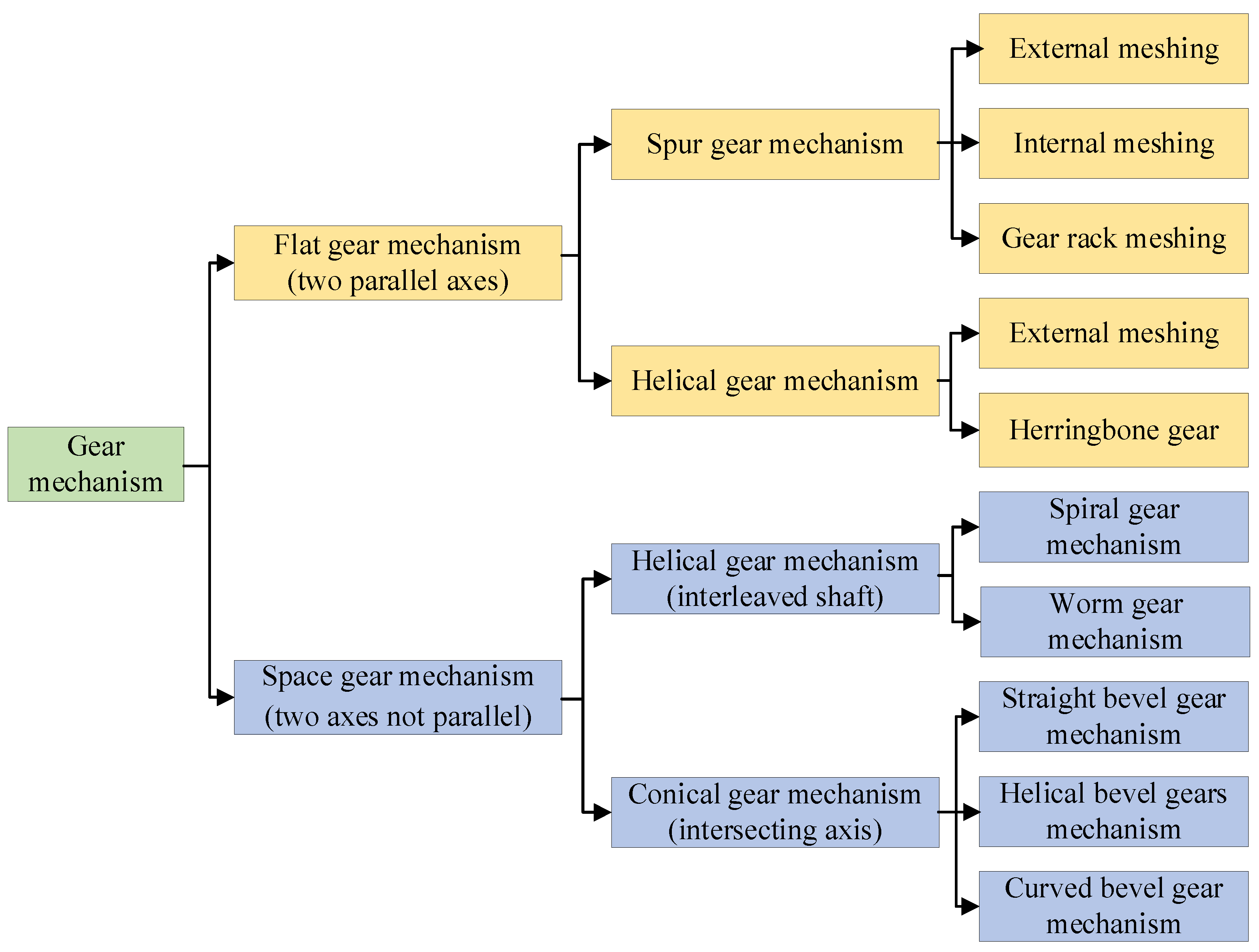
Figure 2.
HCR spur gear model [32].
Figure 2.
HCR spur gear model [32].
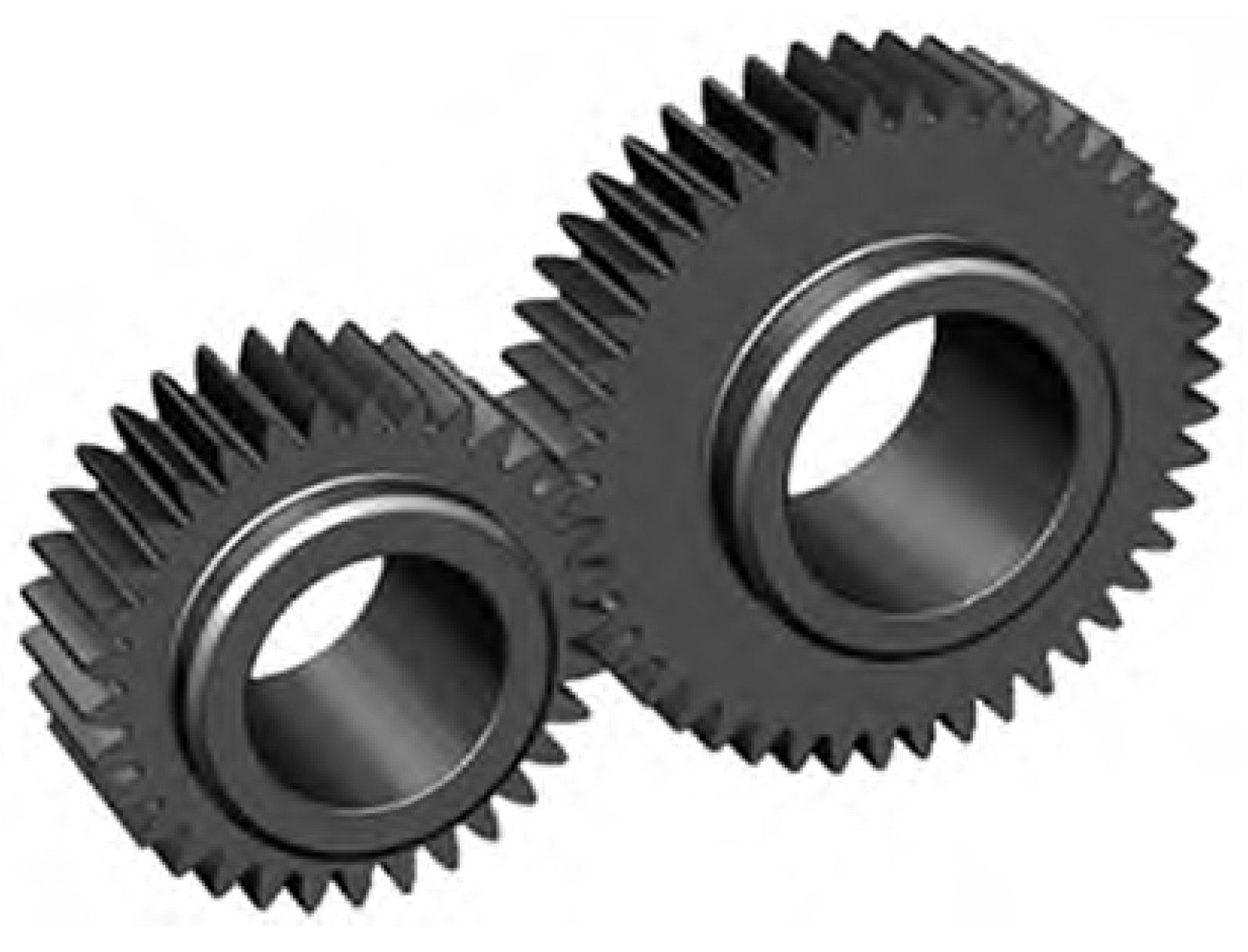
Figure 3.
Helical gear model [35].
Figure 3.
Helical gear model [35].
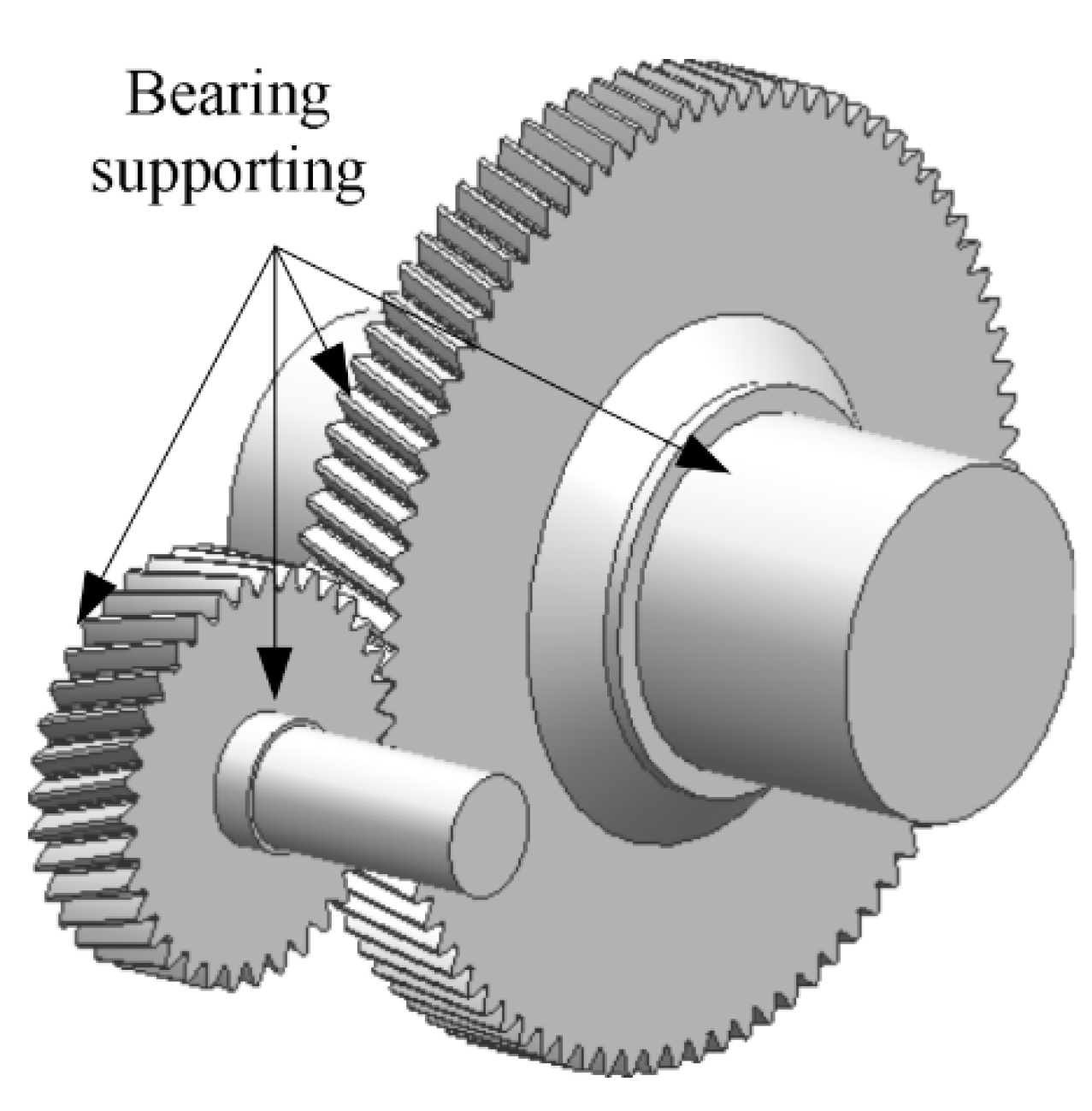
Figure 4.
Face gear pair coordinate system [38].
Figure 4.
Face gear pair coordinate system [38].
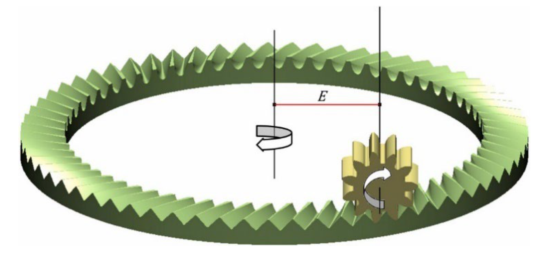
Figure 5.
Dual guide bias worm model [46].
Figure 5.
Dual guide bias worm model [46].
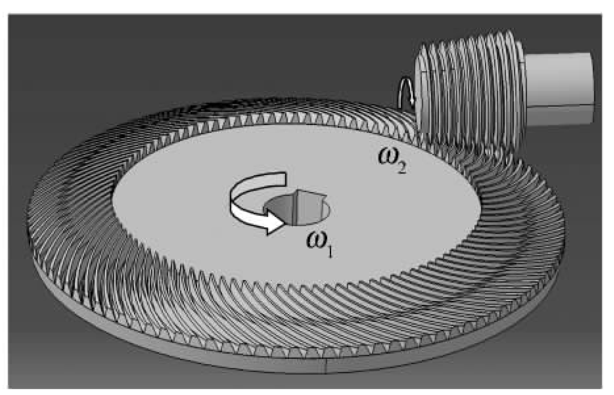
Figure 6.
Linear contact surface worm gear transmission model [47].47.
Figure 6.
Linear contact surface worm gear transmission model [47].47.
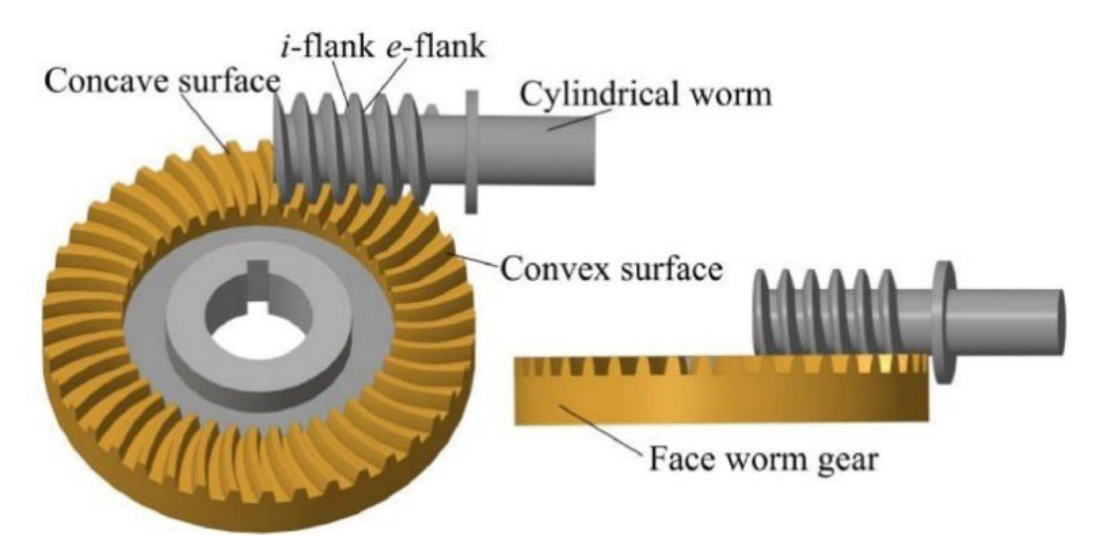
Figure 7.
NCSB-gear pair model [48].
Figure 7.
NCSB-gear pair model [48].
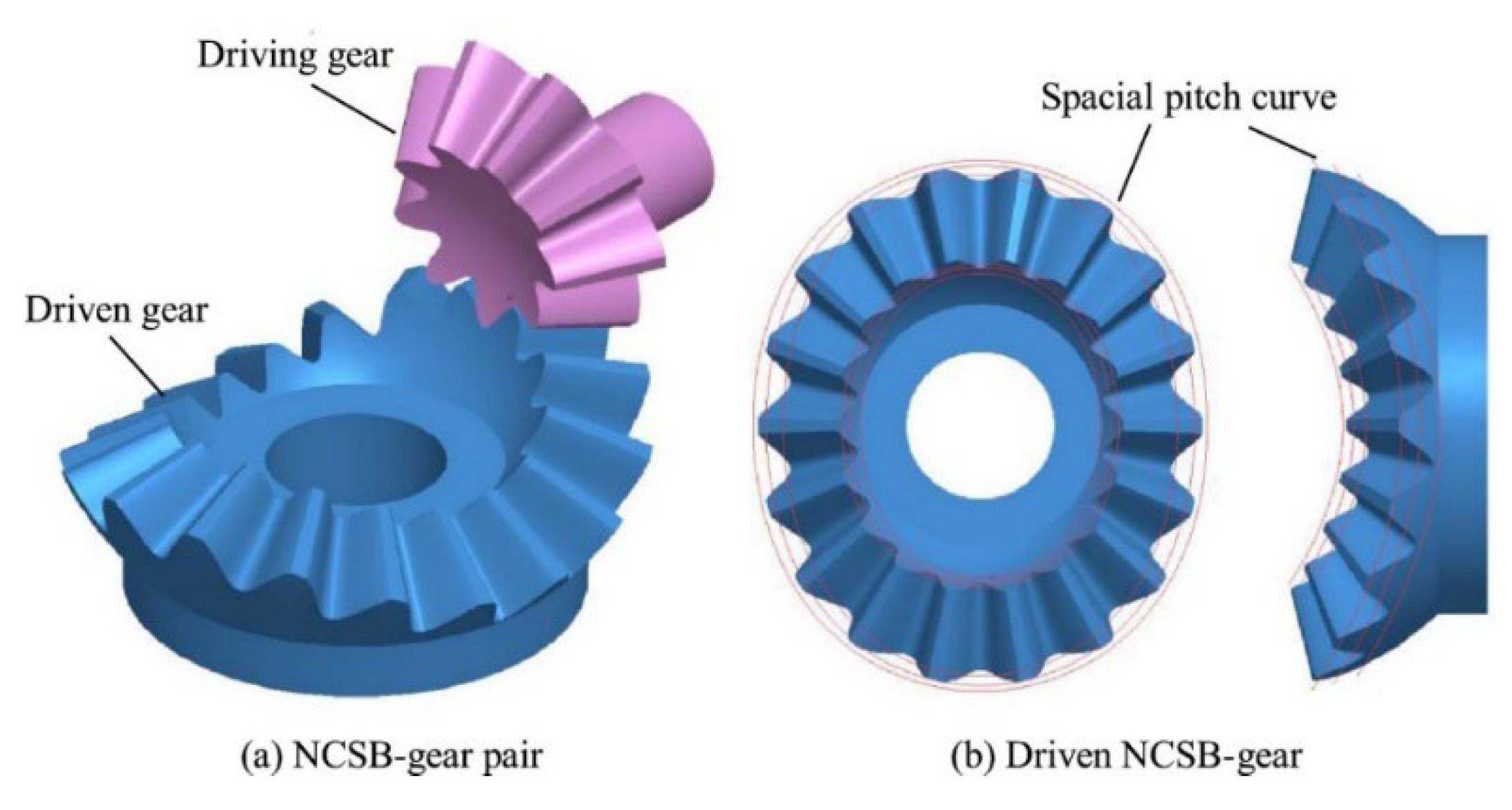
Figure 8.
Cycloid bevel gear pair model [49].
Figure 8.
Cycloid bevel gear pair model [49].
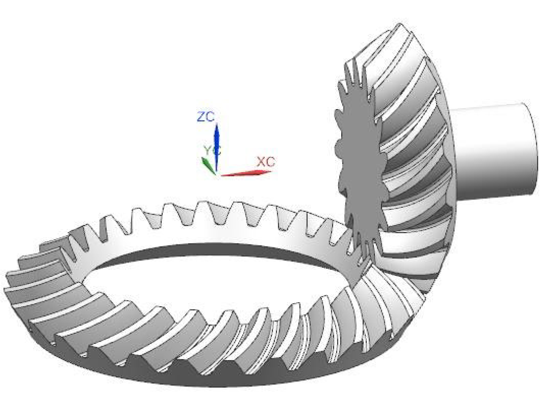
Figure 9.
Hyperbolic gear pair model [51].
Figure 9.
Hyperbolic gear pair model [51].
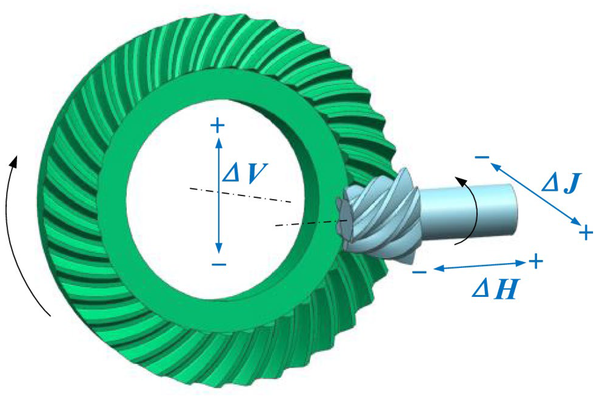
Figure 10.
The dexterous joint structure of DISGs [52].
Figure 10.
The dexterous joint structure of DISGs [52].
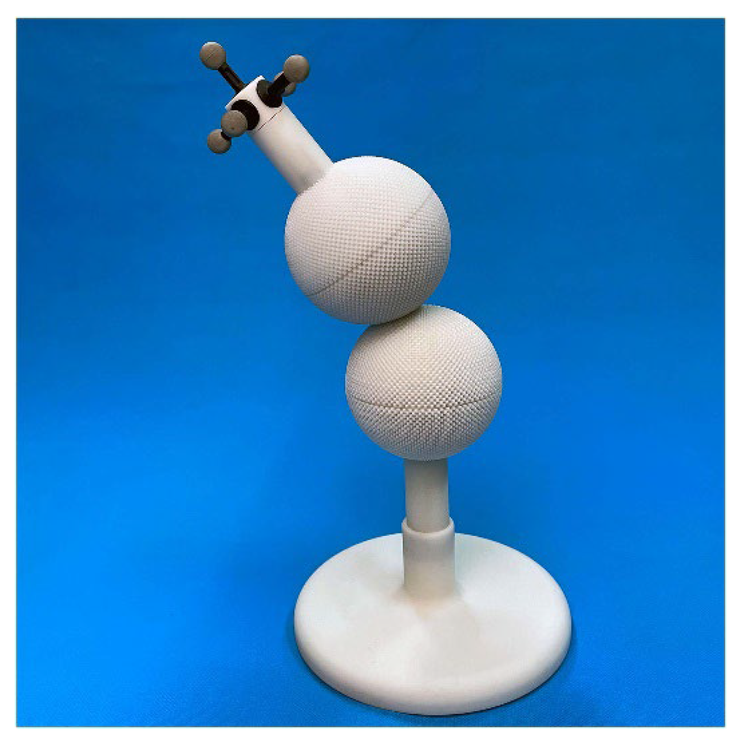
Figure 11.
Performance experiment of spherical gear mechanism [53].
Figure 11.
Performance experiment of spherical gear mechanism [53].
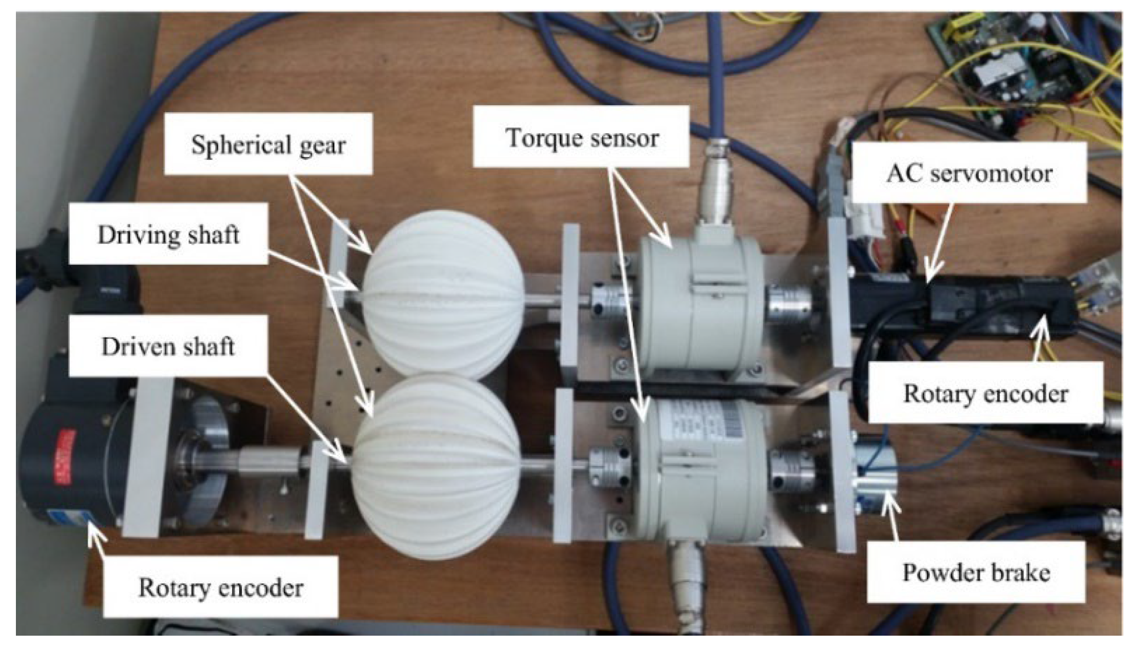
Figure 12.
Non-circular gear planetary system (four different configurations of sun gear fixed on the frame) [55].
Figure 12.
Non-circular gear planetary system (four different configurations of sun gear fixed on the frame) [55].
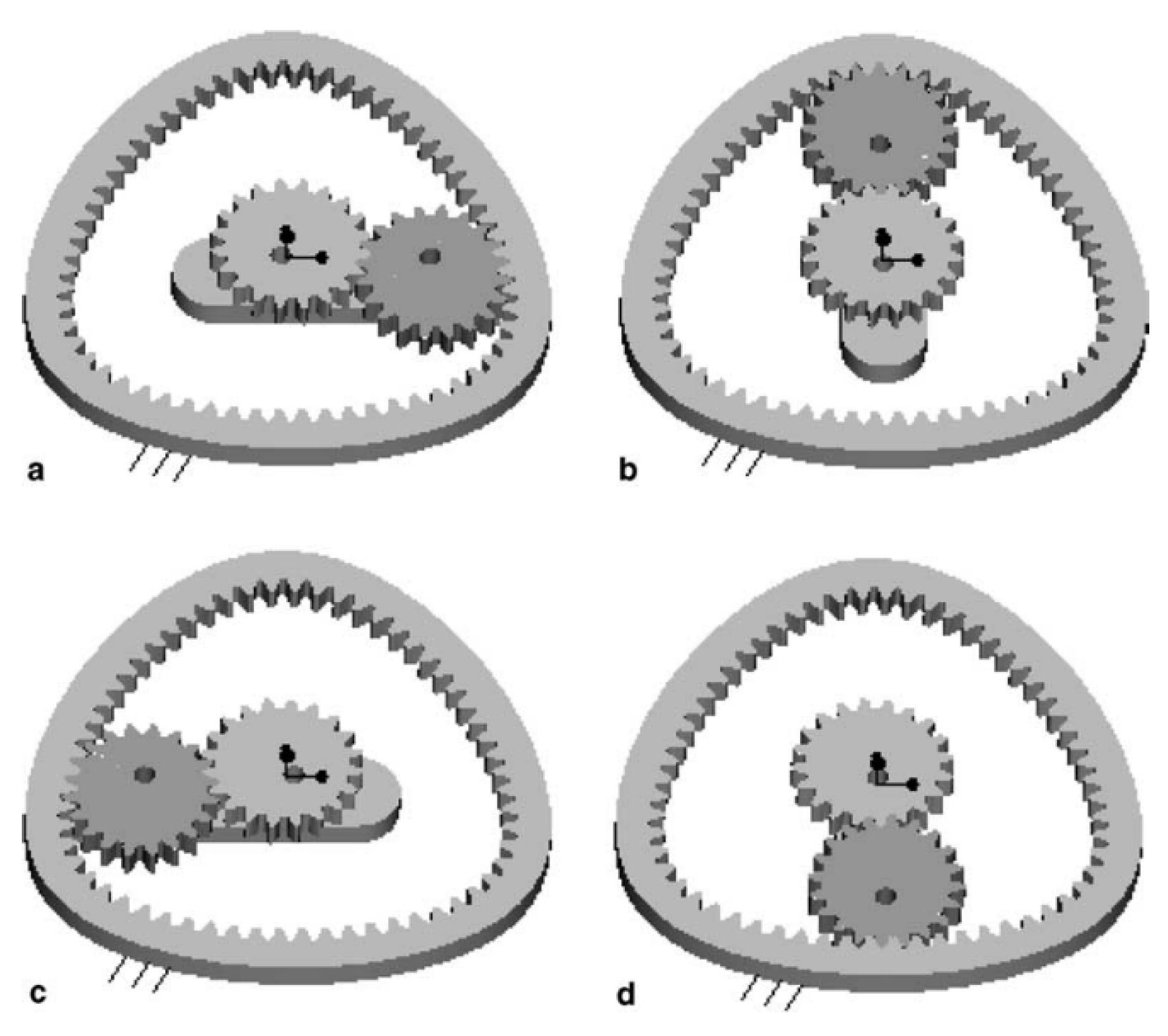
Figure 13.
Schematic diagram of non-circular gear mechanism: 1. active gear,2. passive gear [56].
Figure 13.
Schematic diagram of non-circular gear mechanism: 1. active gear,2. passive gear [56].
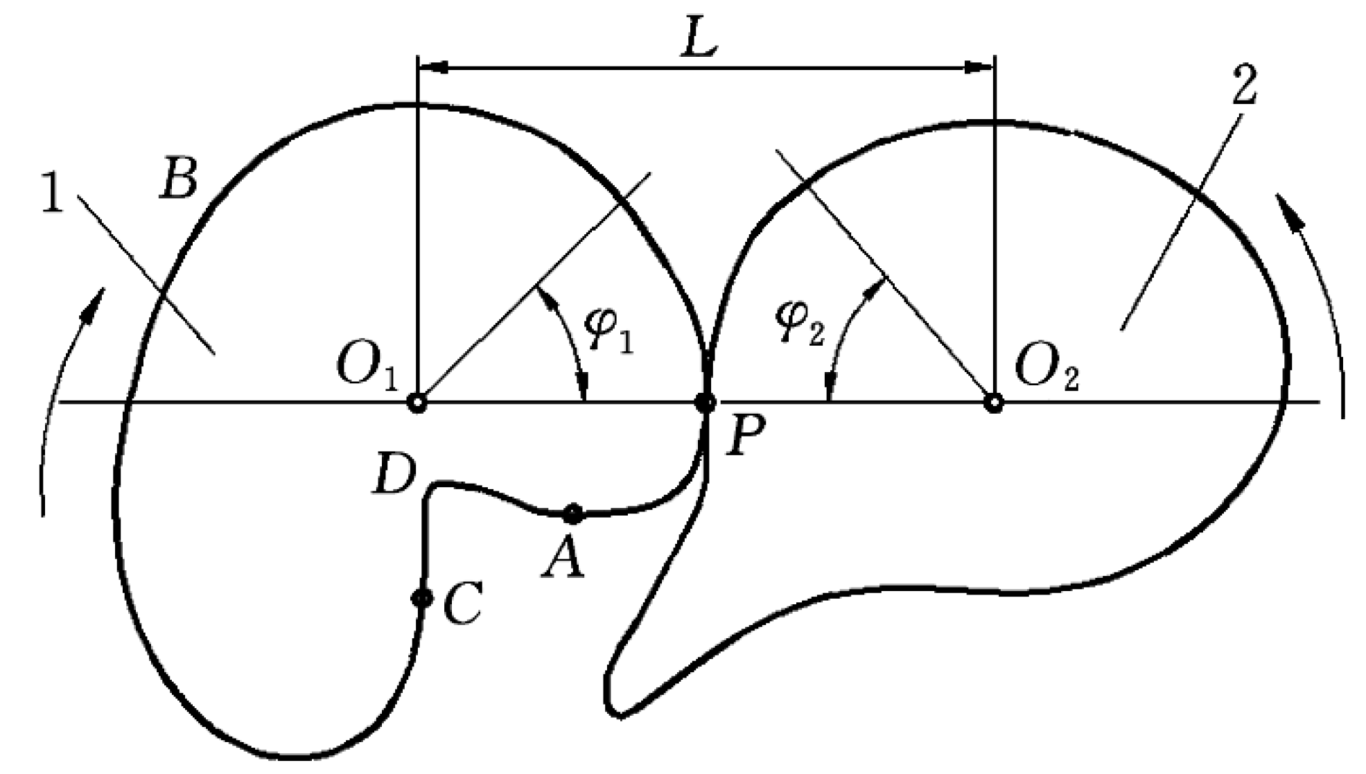
Figure 14.
VLG pair mechanism: (a) parallel axis and (b) intersecting axis [57].
Figure 14.
VLG pair mechanism: (a) parallel axis and (b) intersecting axis [57].
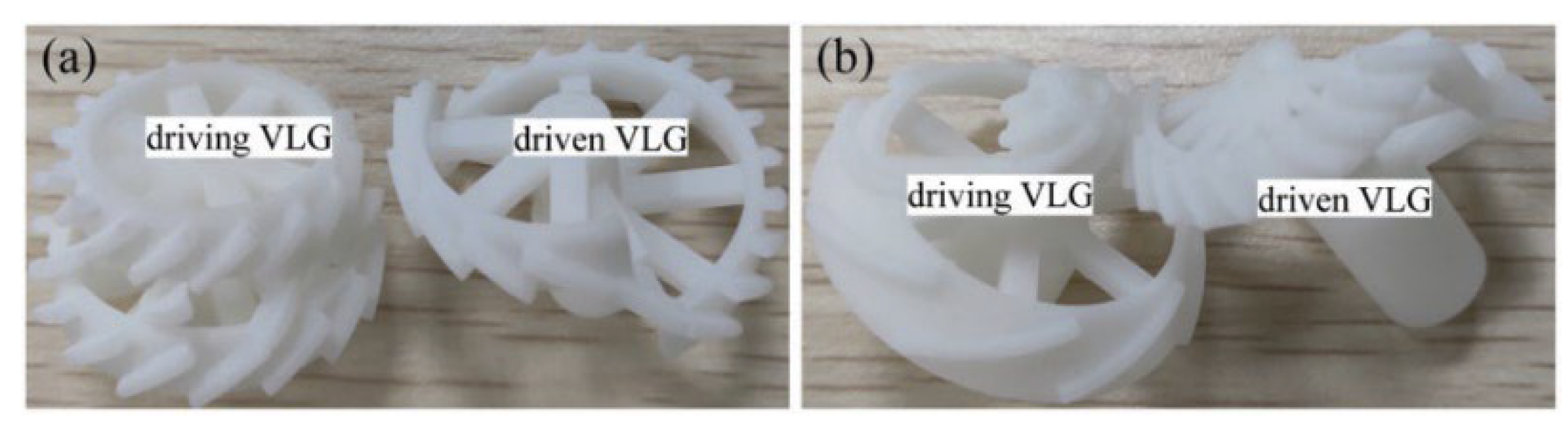
Figure 15.
Kinematic test bench for VLG auxiliary mechanism: (a) parallel axis and (B) intersecting axis [57].
Figure 15.
Kinematic test bench for VLG auxiliary mechanism: (a) parallel axis and (B) intersecting axis [57].
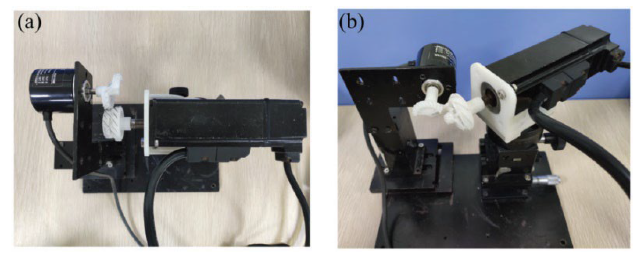
Figure 16.
Pair 1 installed on the test rig [58].
Figure 16.
Pair 1 installed on the test rig [58].
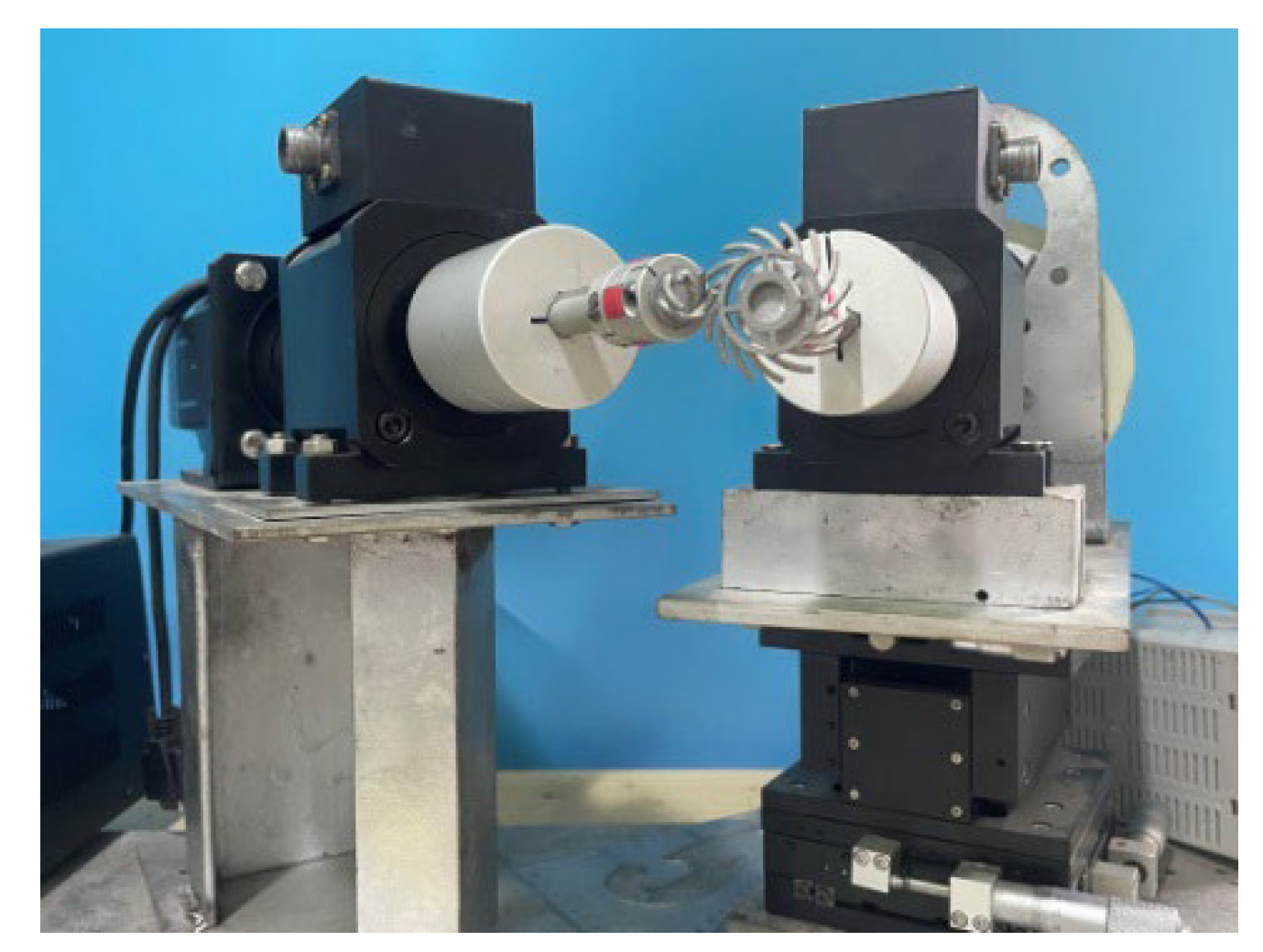
Figure 17.
Non-relative sliding gear mechanism with parallel axis transmission, (a) uniform motion at the meshing point, (b) uniform acceleration motion at the meshing point [59].
Figure 17.
Non-relative sliding gear mechanism with parallel axis transmission, (a) uniform motion at the meshing point, (b) uniform acceleration motion at the meshing point [59].
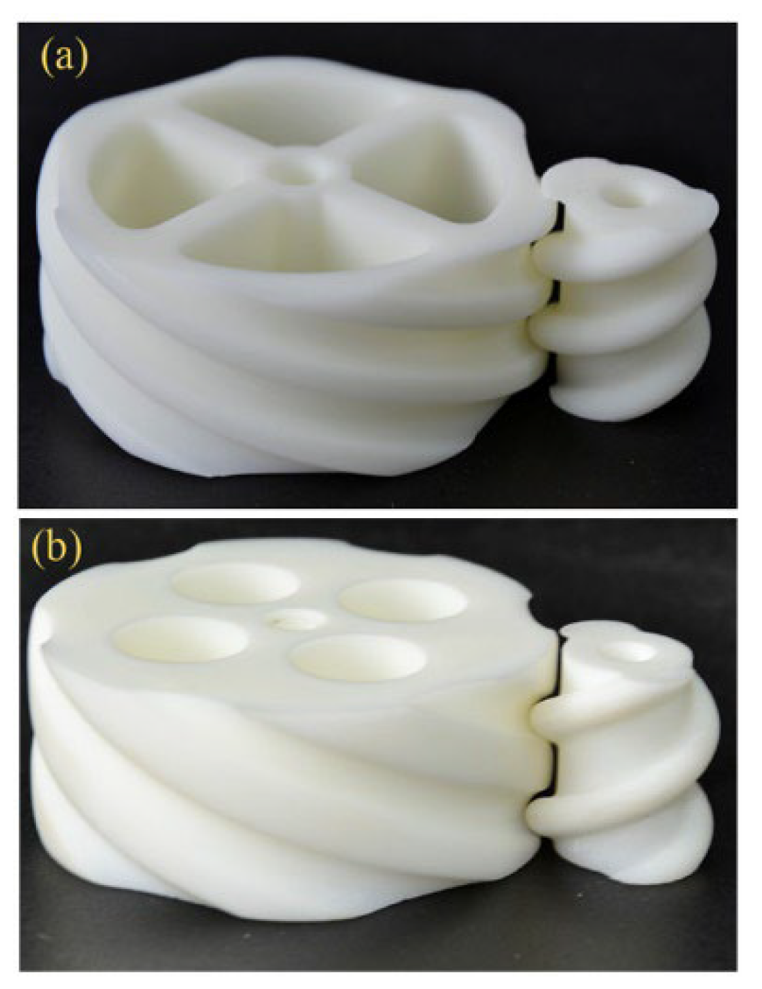
Figure 18.
Kinematic performance test of the mechanism: (a) uniform motion of the meshing point, (b) uniform acceleration motion of the meshing point [59].
Figure 18.
Kinematic performance test of the mechanism: (a) uniform motion of the meshing point, (b) uniform acceleration motion of the meshing point [59].
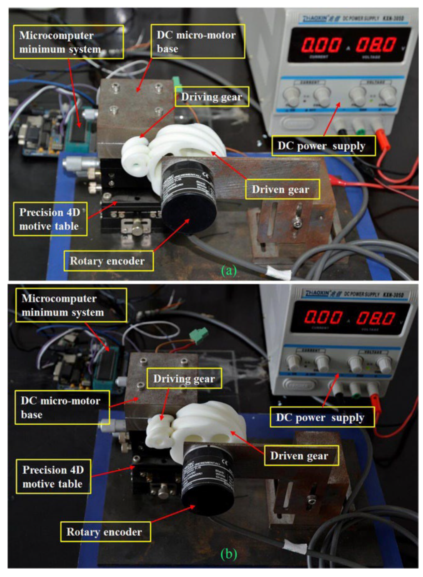
Figure 19.
Model of Double Cycloid Gear Pair Pre tensioned Gear Mechanism [60].
Figure 19.
Model of Double Cycloid Gear Pair Pre tensioned Gear Mechanism [60].
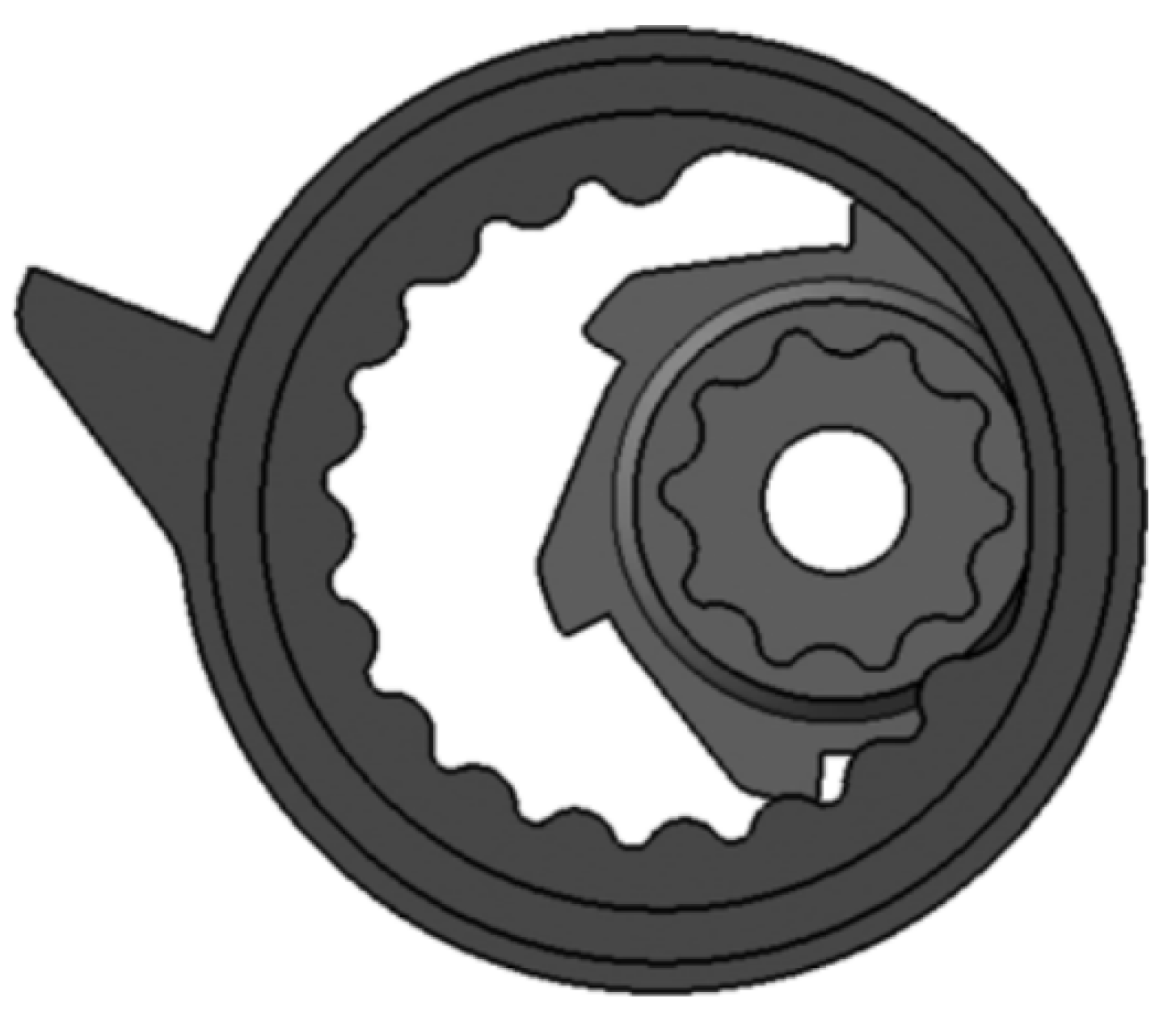
Figure 20.
Schematic diagram of a single permanent magnet array coaxial magnetic gear [62].
Figure 20.
Schematic diagram of a single permanent magnet array coaxial magnetic gear [62].
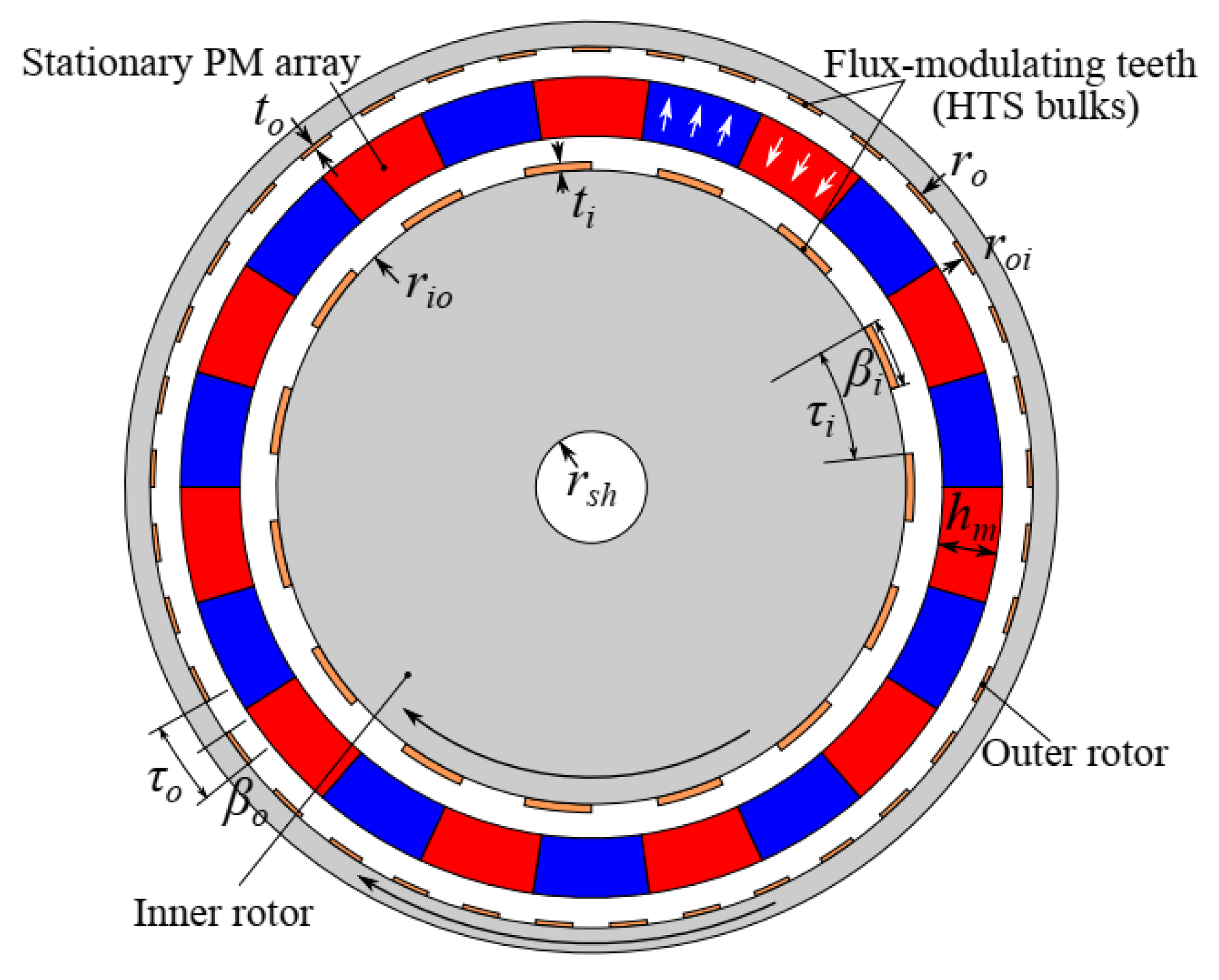
Figure 21.
Improved magnetic gear model [63].63.
Figure 21.
Improved magnetic gear model [63].63.
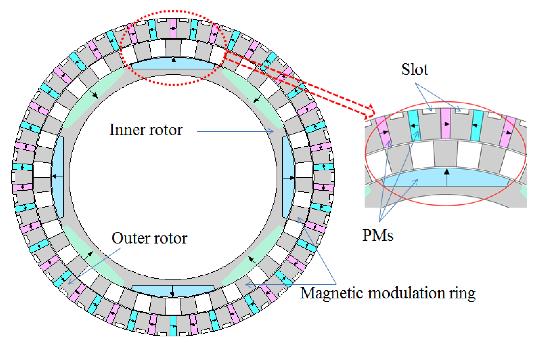
Figure 22.
Topological Model of Axial Magnetic Flux Modulation Superconducting Magnetic Gear [65].
Figure 22.
Topological Model of Axial Magnetic Flux Modulation Superconducting Magnetic Gear [65].
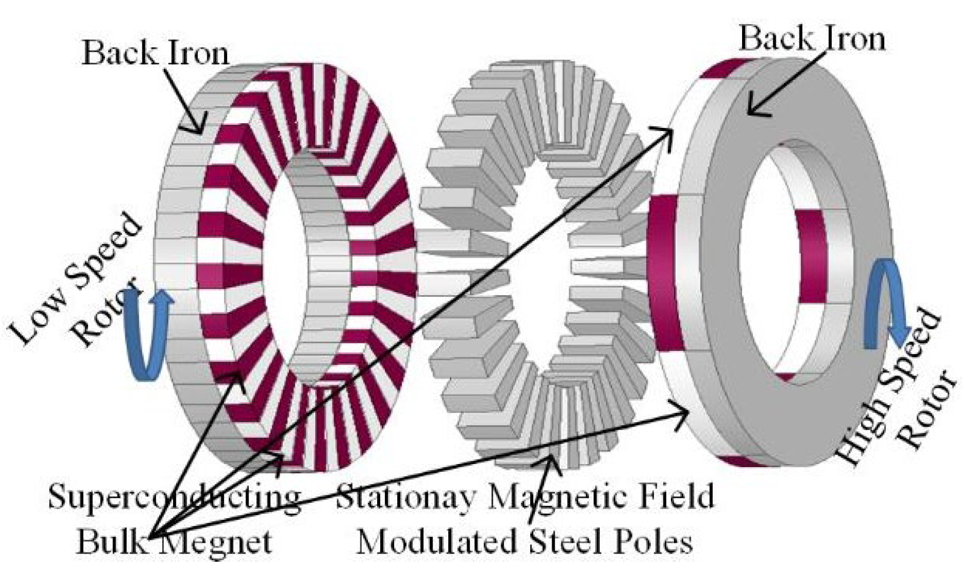
Figure 23.
Structure of the TVB: (a) a V-belt drive system with the TVB, (b) A-A sectional view, (c) an exploded view, (d–e) SEM images of the cross-section and surface of the V-belt, and (f) photograph of the fabricated TVB [70].
Figure 23.
Structure of the TVB: (a) a V-belt drive system with the TVB, (b) A-A sectional view, (c) an exploded view, (d–e) SEM images of the cross-section and surface of the V-belt, and (f) photograph of the fabricated TVB [70].
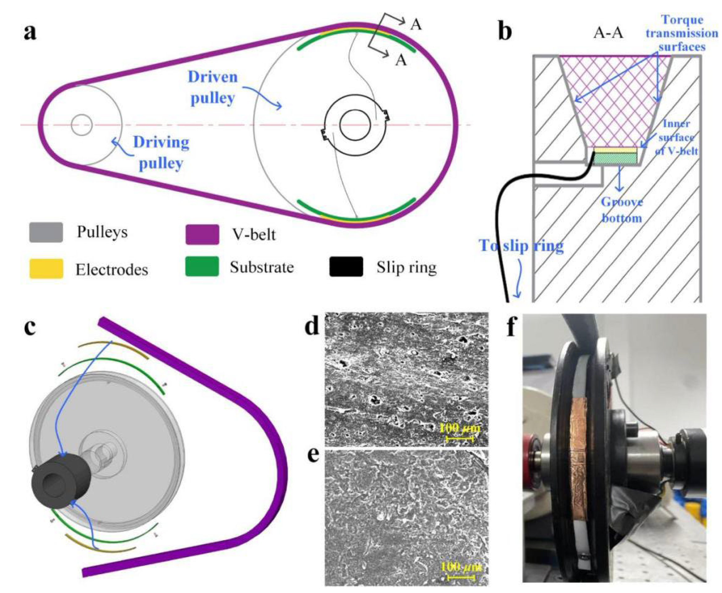
Figure 24.
Schematic diagram of a new type of non-circular pulley transmission [71].
Figure 24.
Schematic diagram of a new type of non-circular pulley transmission [71].
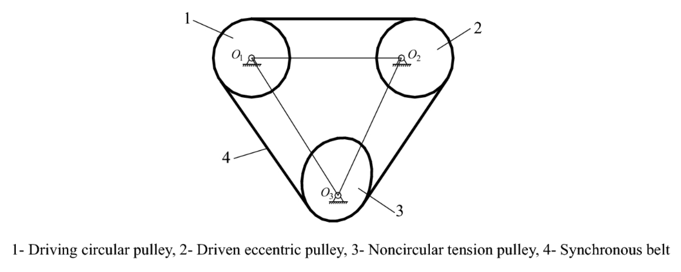
Figure 25.
Modern Roller Chain Structure [73].
Figure 25.
Modern Roller Chain Structure [73].
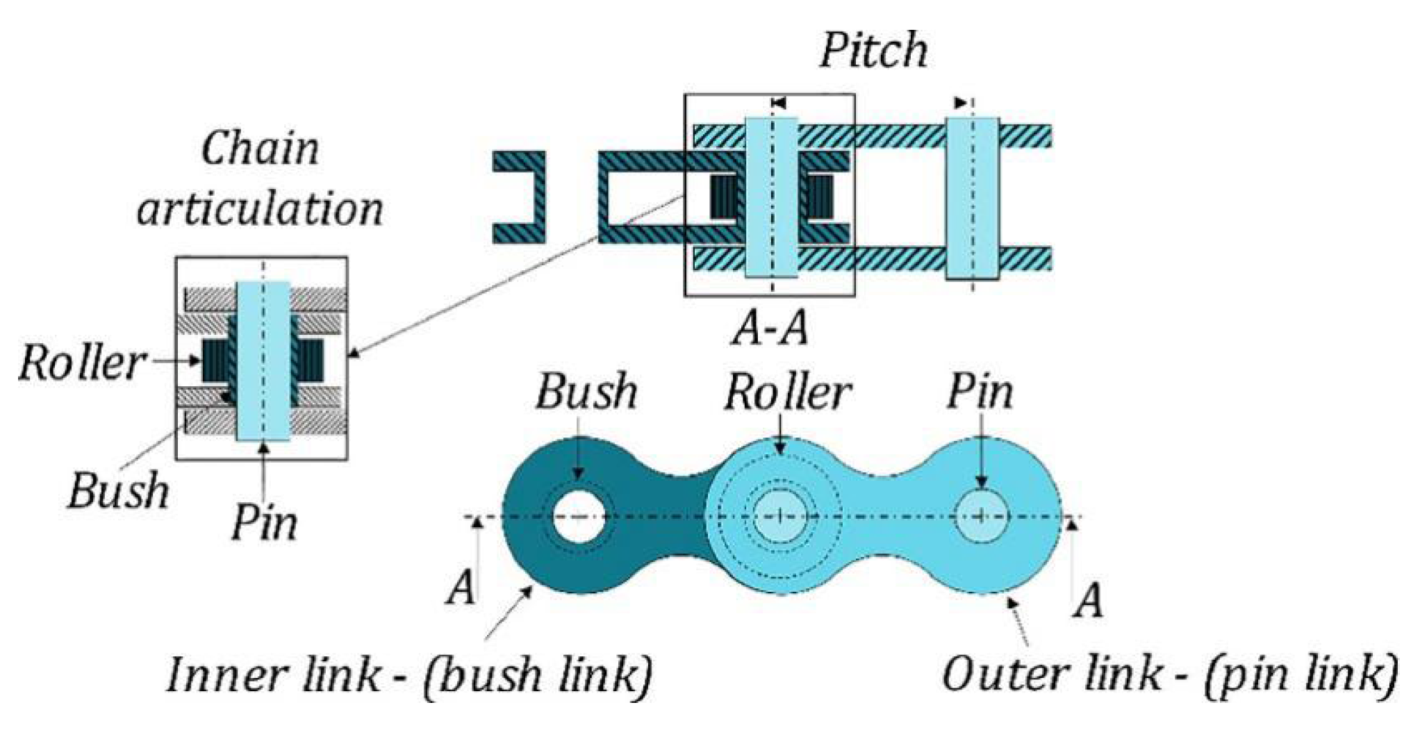
Figure 26.
Schematic diagram of chain drive [73].
Figure 26.
Schematic diagram of chain drive [73].
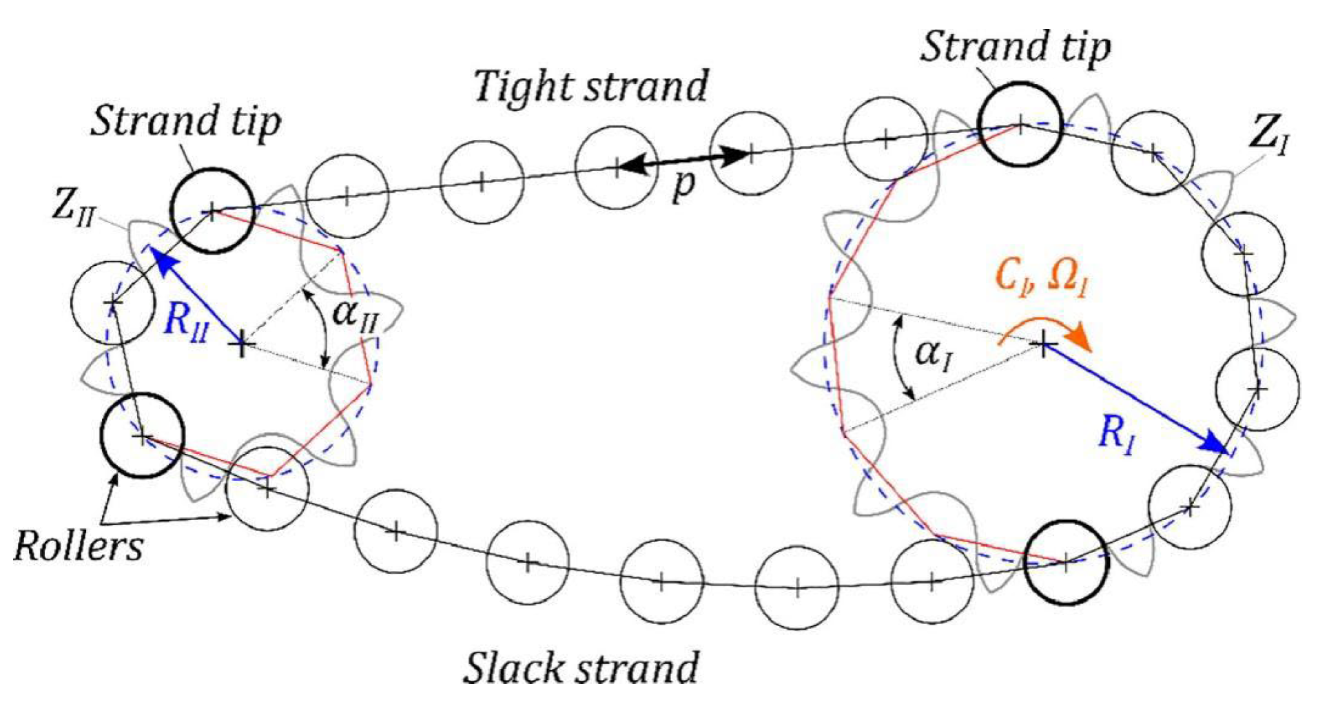
Figure 27.
Multiple rows of sprockets [74].
Figure 27.
Multiple rows of sprockets [74].
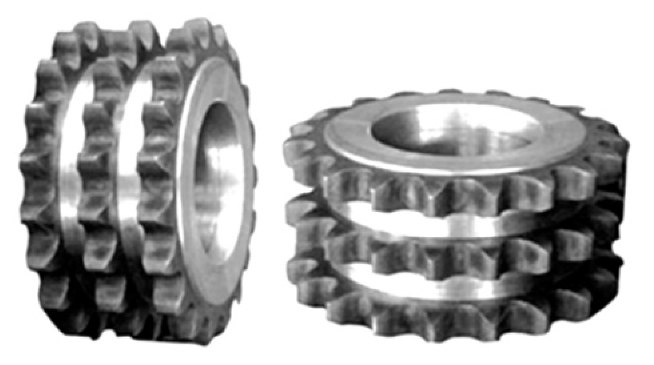
Figure 28.
Partial silent chain transmission system in a certain automobile engine [75].
Figure 28.
Partial silent chain transmission system in a certain automobile engine [75].
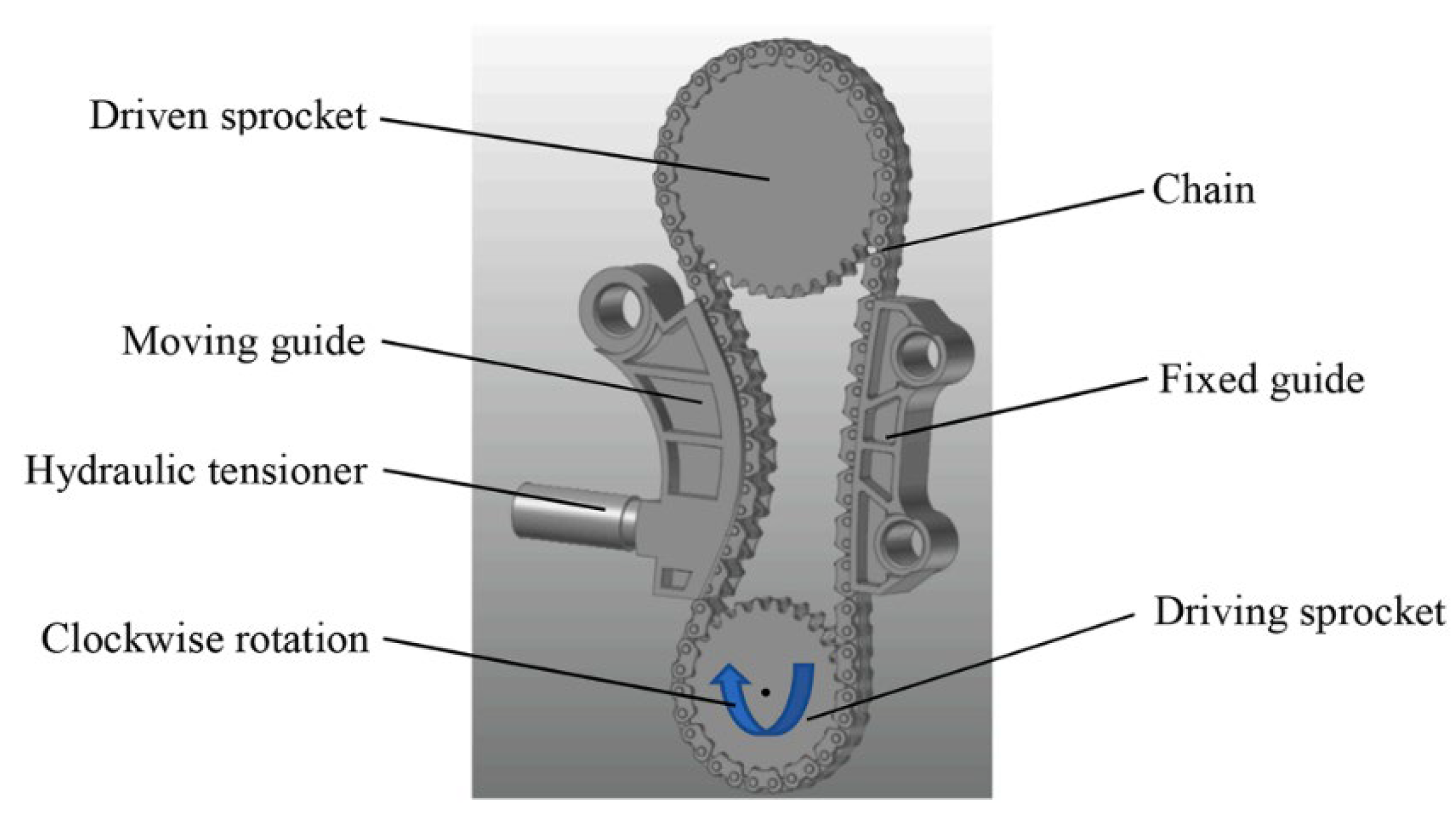
Figure 29.
Dynamic model of a novel single-toothed chain plate two-phase chain transmission system [76].
Figure 29.
Dynamic model of a novel single-toothed chain plate two-phase chain transmission system [76].
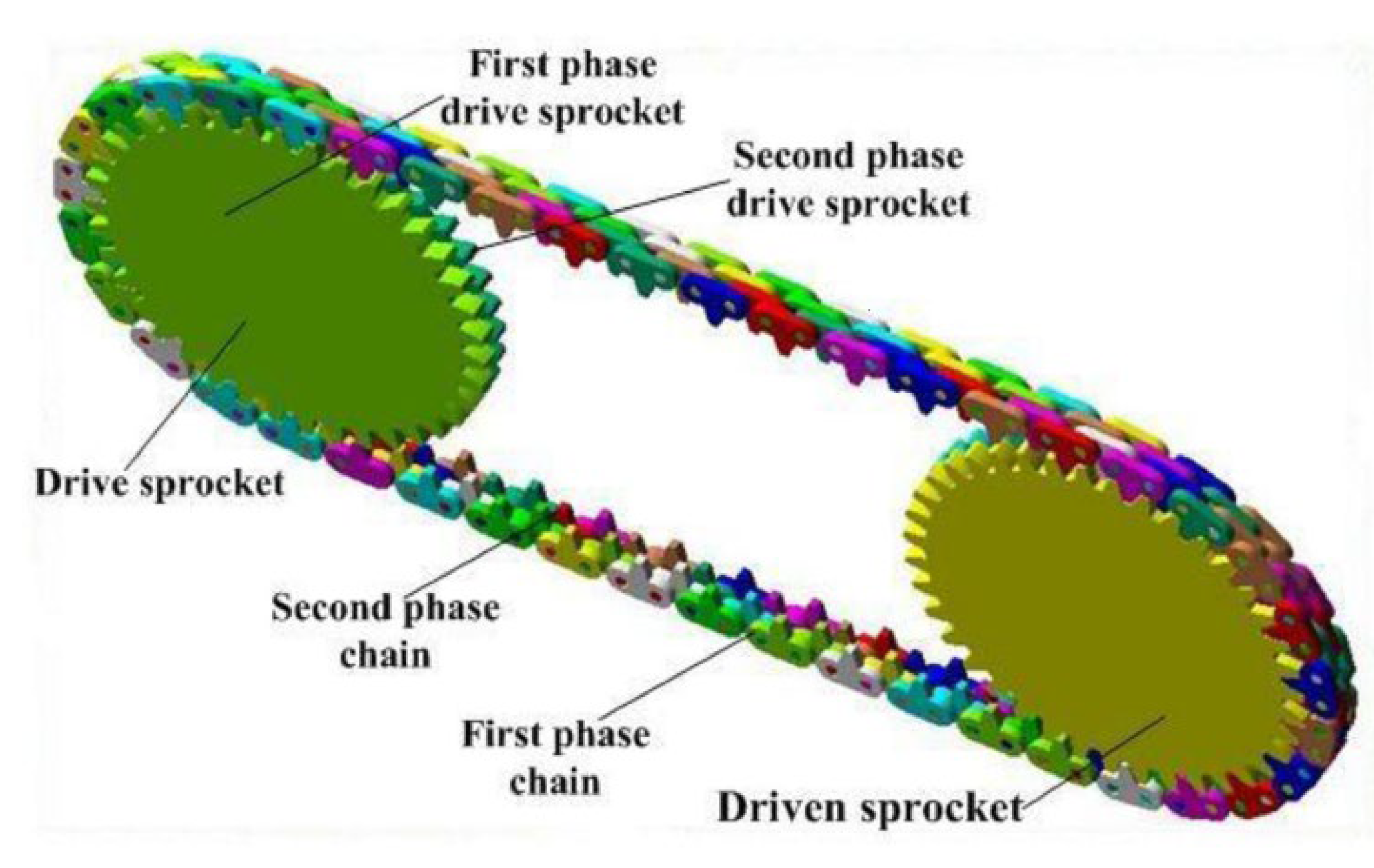
Figure 30.
Inner and outer panels of composite materials [77].
Figure 30.
Inner and outer panels of composite materials [77].
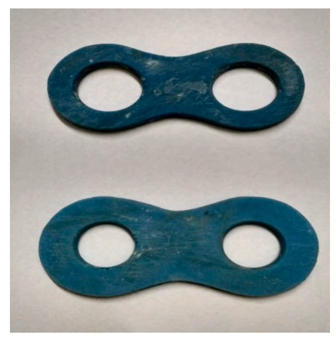
Figure 31.
Schematic diagram of cam roller [80].
Figure 31.
Schematic diagram of cam roller [80].
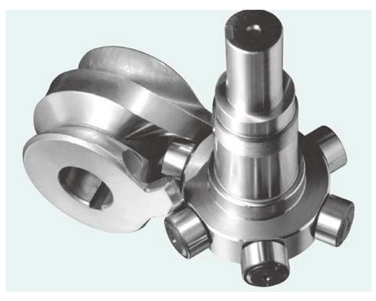
Figure 32.
A pair of counterweight conjugate cam mechanism models [84].
Figure 32.
A pair of counterweight conjugate cam mechanism models [84].
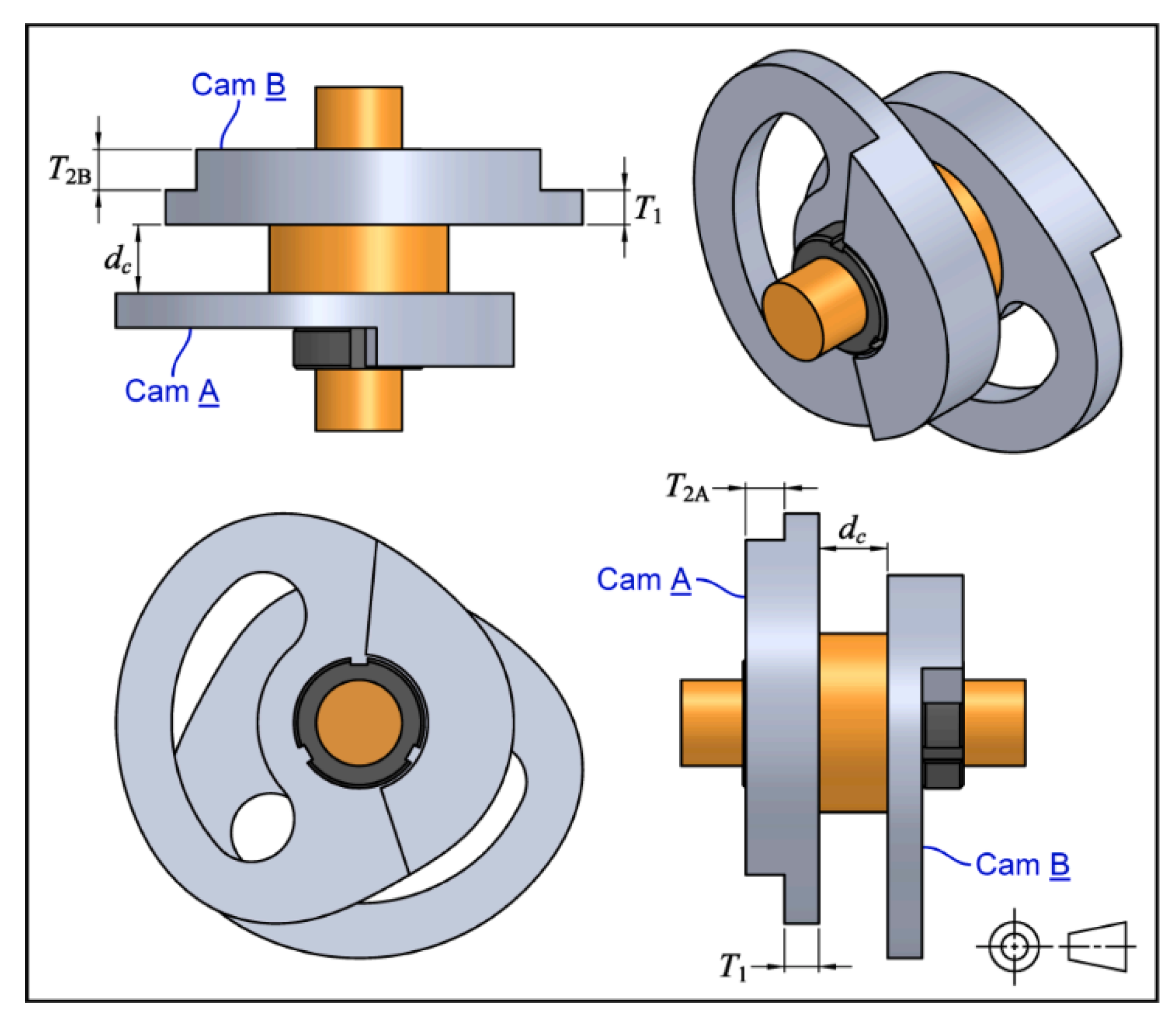
Figure 33.
A. Schematic diagram of a cylindrical cam actuator. (a) Extended state, (b) mid-stroke, and (c) compressed state; B. Physical cylindrical cam shock absorber [86].
Figure 33.
A. Schematic diagram of a cylindrical cam actuator. (a) Extended state, (b) mid-stroke, and (c) compressed state; B. Physical cylindrical cam shock absorber [86].
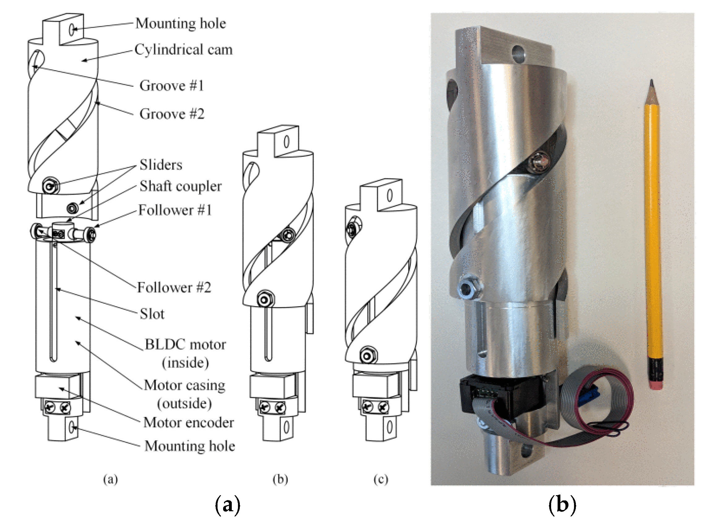
Figure 34.
Schematic diagram of ratchet mechanism and its components: (a) Linear ratchet; (b) Rotate the ratchet wheel [87].
Figure 34.
Schematic diagram of ratchet mechanism and its components: (a) Linear ratchet; (b) Rotate the ratchet wheel [87].
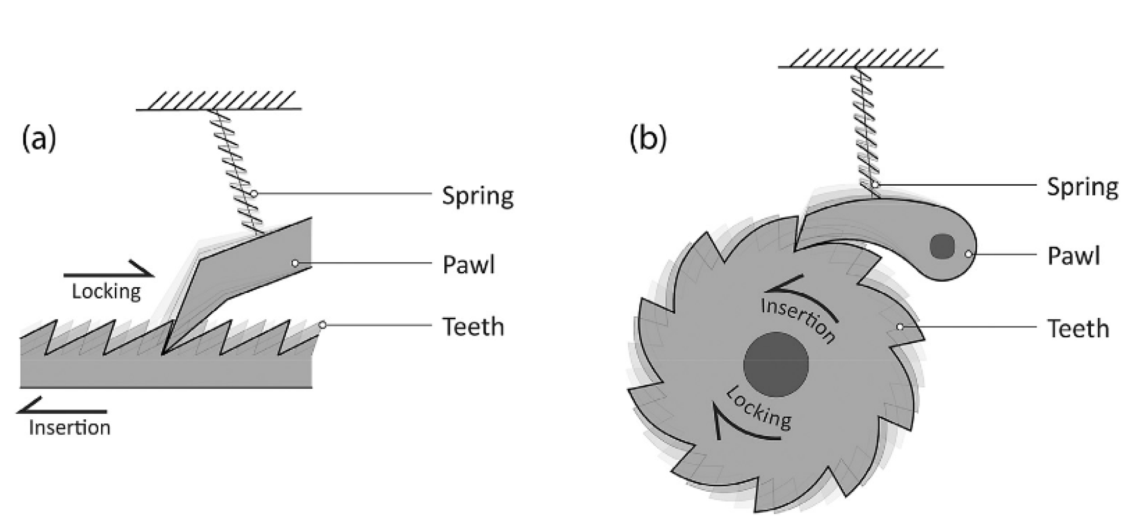
Figure 35.
The prescribed boundary conditions for (a) insertion and (b) locking direction of the flexible ratchet mechanism model [87].
Figure 35.
The prescribed boundary conditions for (a) insertion and (b) locking direction of the flexible ratchet mechanism model [87].
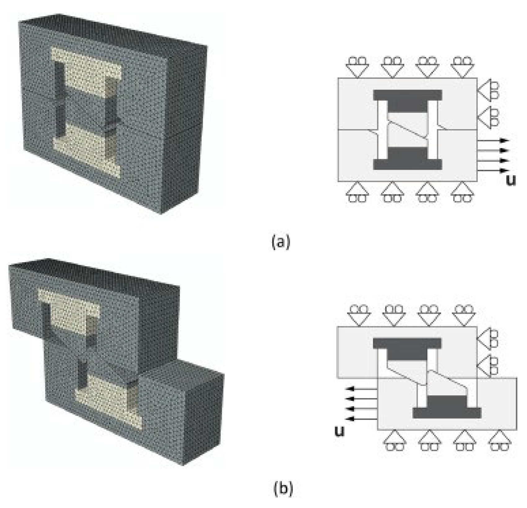
Figure 36.
Four types of ratchet mechanisms (12 teeth and 24 teeth) were printed using PLA and ABS materials [92].
Figure 36.
Four types of ratchet mechanisms (12 teeth and 24 teeth) were printed using PLA and ABS materials [92].
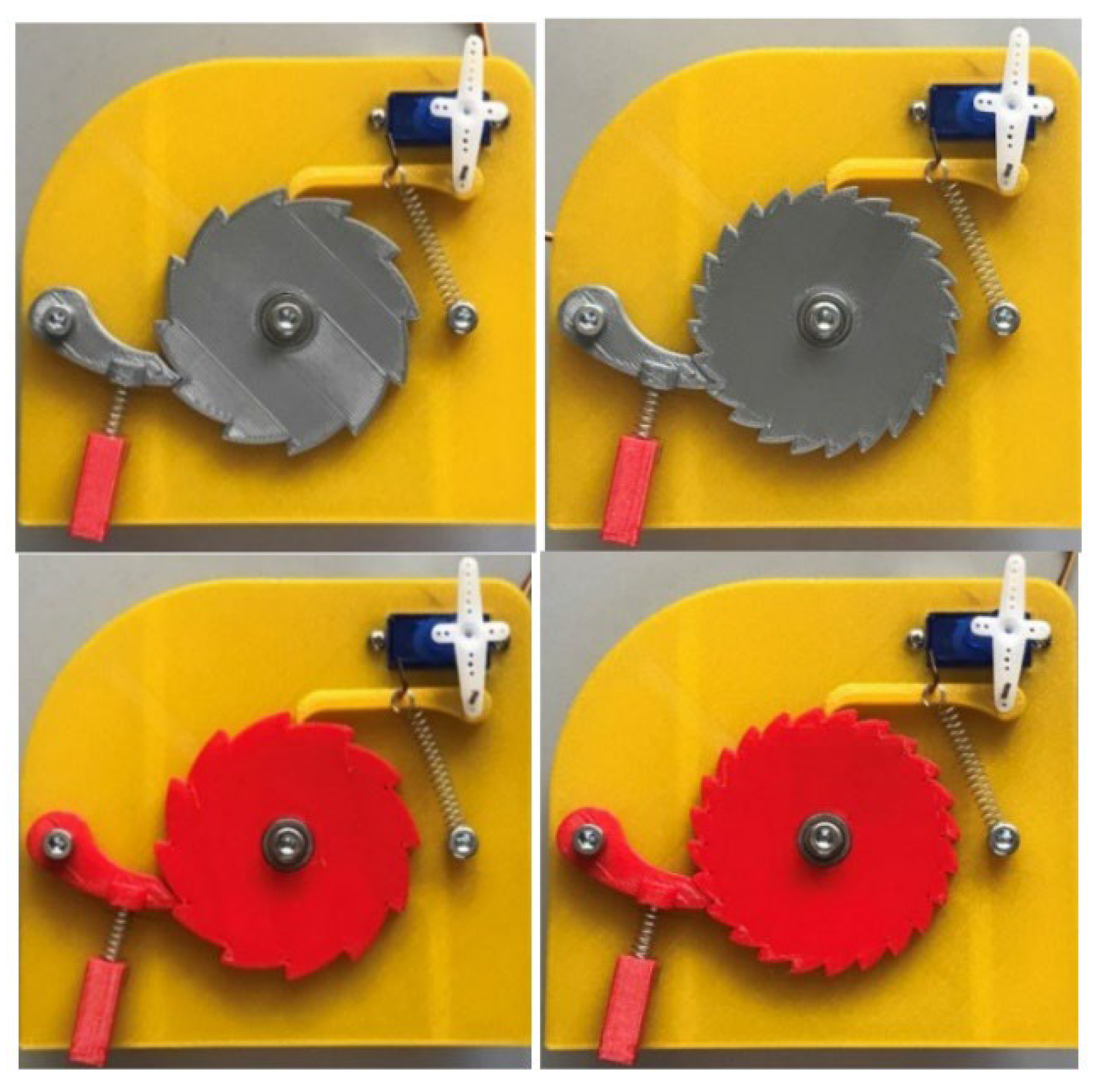
Figure 37.
Schematic diagram of crank rocker mechanism [99].
Figure 37.
Schematic diagram of crank rocker mechanism [99].
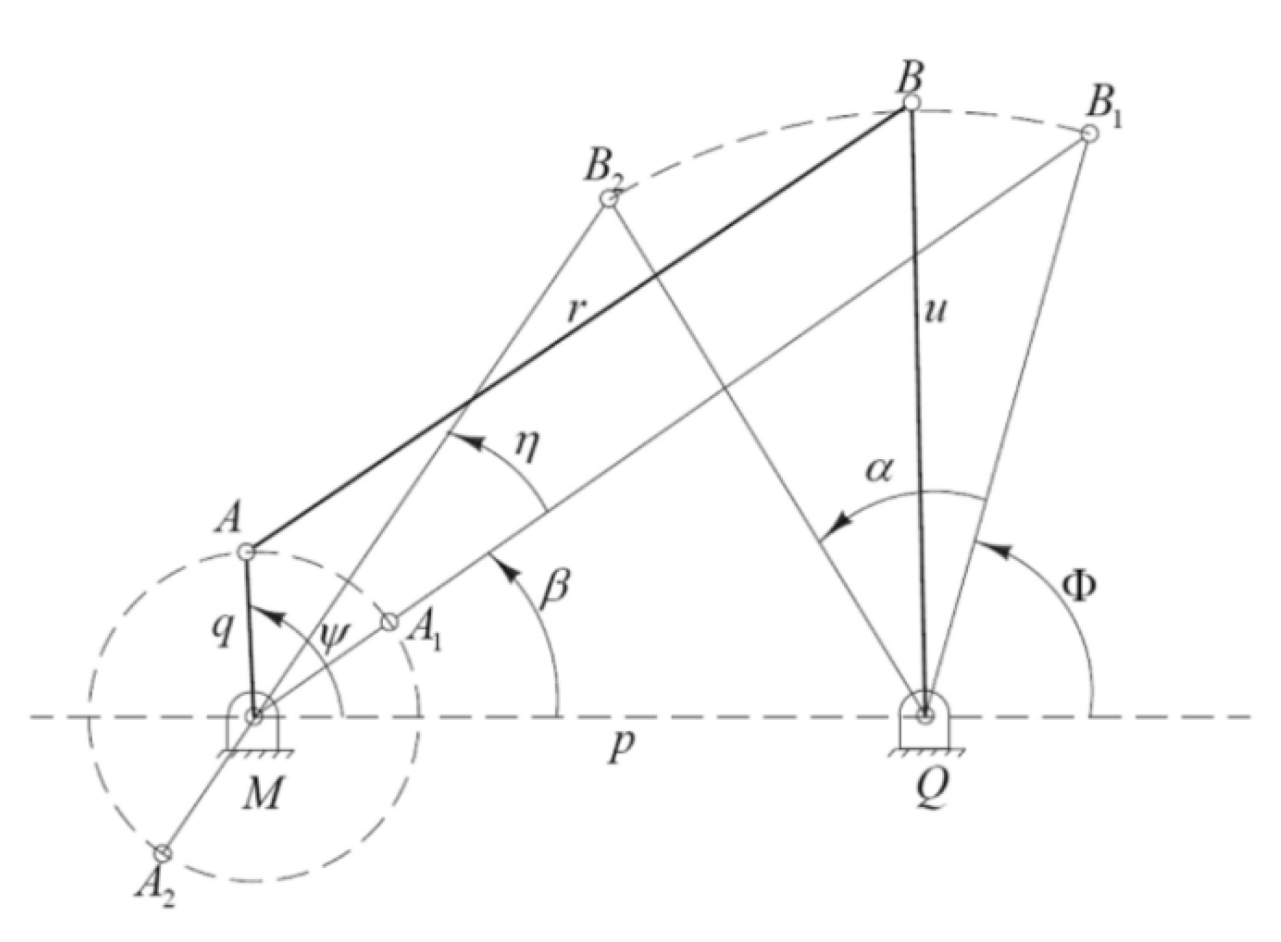
Figure 38.
Geometric representation of the mechanism. M and M ’represent the crank position, while P and P’ represent the corresponding rocker positions at the initial time and time t [100].
Figure 38.
Geometric representation of the mechanism. M and M ’represent the crank position, while P and P’ represent the corresponding rocker positions at the initial time and time t [100].
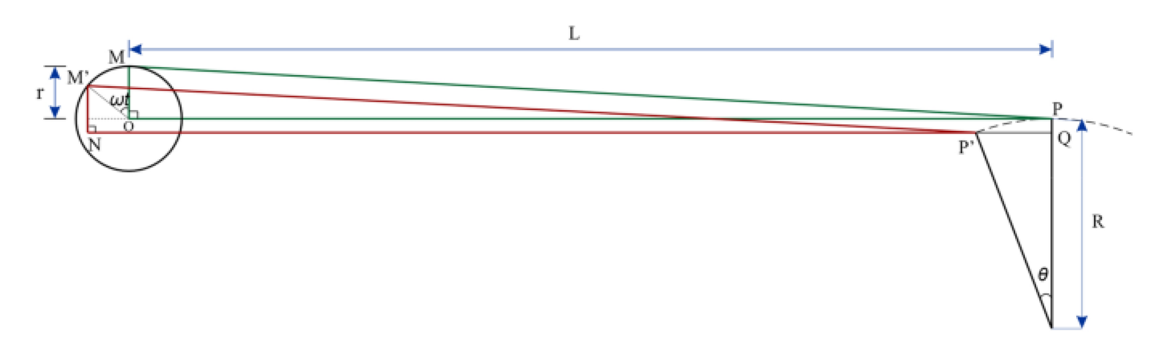
Figure 39.
(a) Top view of the mechanism fixed on the test bench for characterization; (b) Motor with crank installed; (c) The rocker arm/swing arm connected to the airfoil through a shaft. The illustration shows the spiral spring inside the spring housing [100].
Figure 39.
(a) Top view of the mechanism fixed on the test bench for characterization; (b) Motor with crank installed; (c) The rocker arm/swing arm connected to the airfoil through a shaft. The illustration shows the spiral spring inside the spring housing [100].
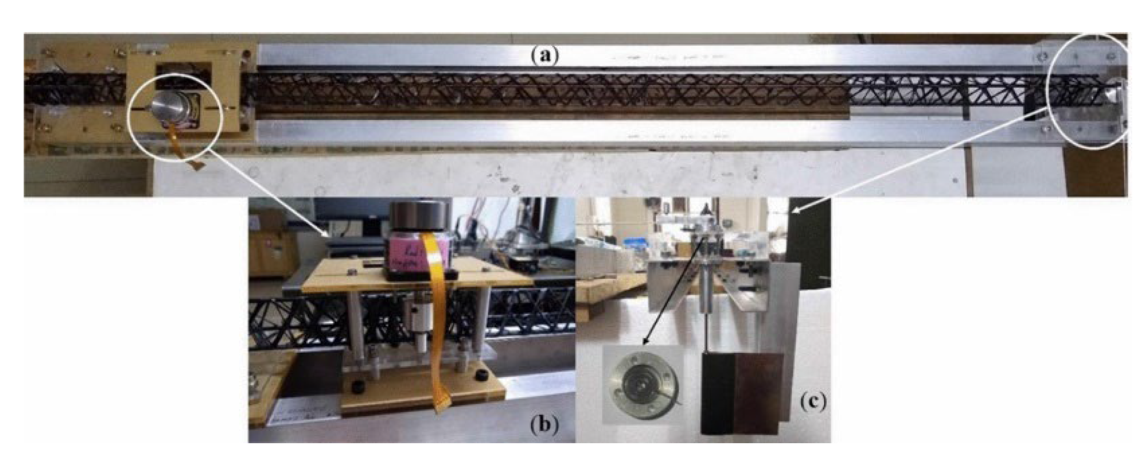
Figure 40.
Schematic diagram of hyperbolic handle mechanism [102].
Figure 40.
Schematic diagram of hyperbolic handle mechanism [102].
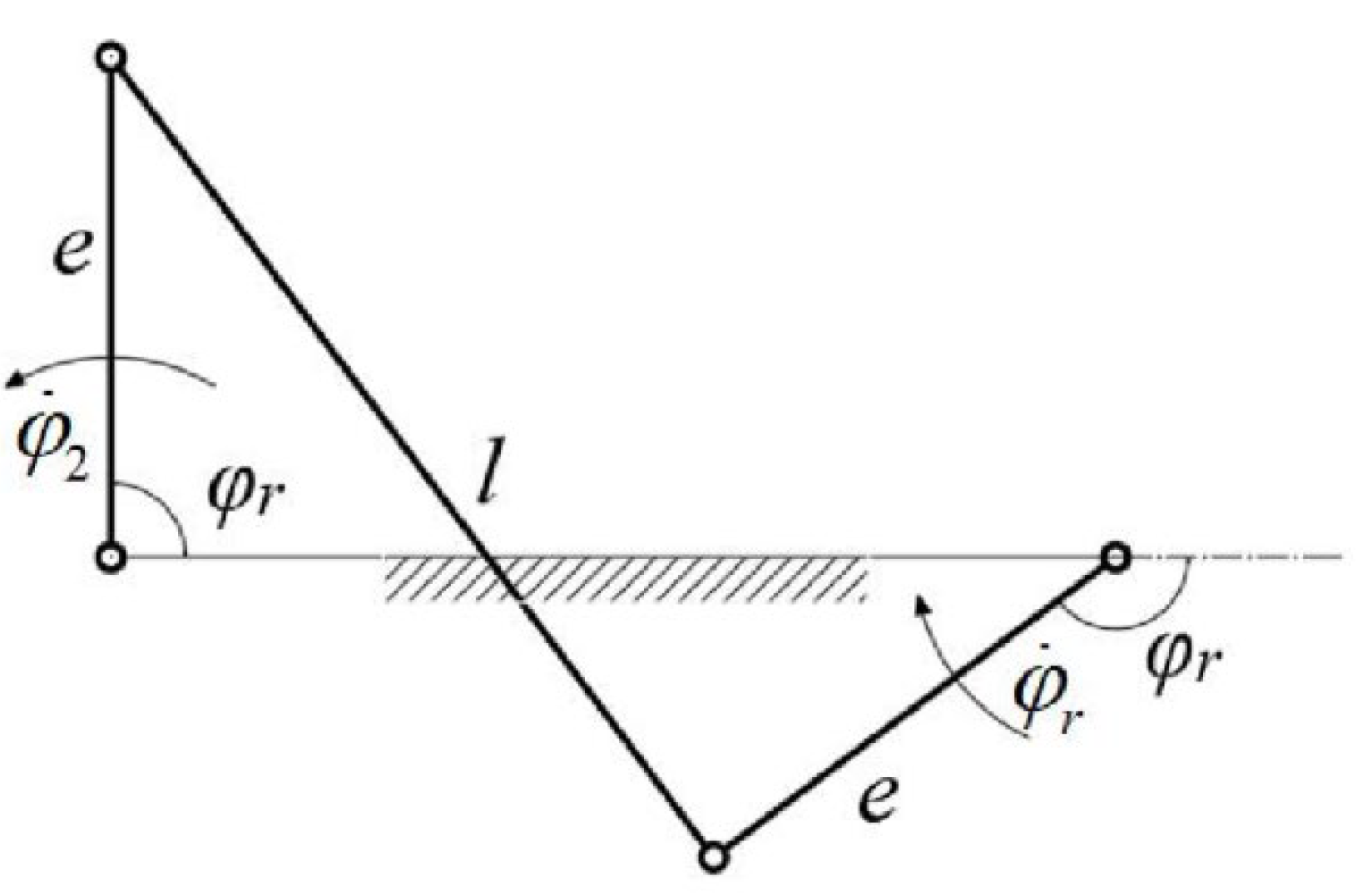
Figure 41.
A neutral and stable four-bar linkage mechanism (orange schematic) consists of a rigid linkage (black) and a helical shell joint (gray). These joints are preloaded to move within a constant torque range. At the bottom, top views of some equilibrium positions are displayed [103].
Figure 41.
A neutral and stable four-bar linkage mechanism (orange schematic) consists of a rigid linkage (black) and a helical shell joint (gray). These joints are preloaded to move within a constant torque range. At the bottom, top views of some equilibrium positions are displayed [103].
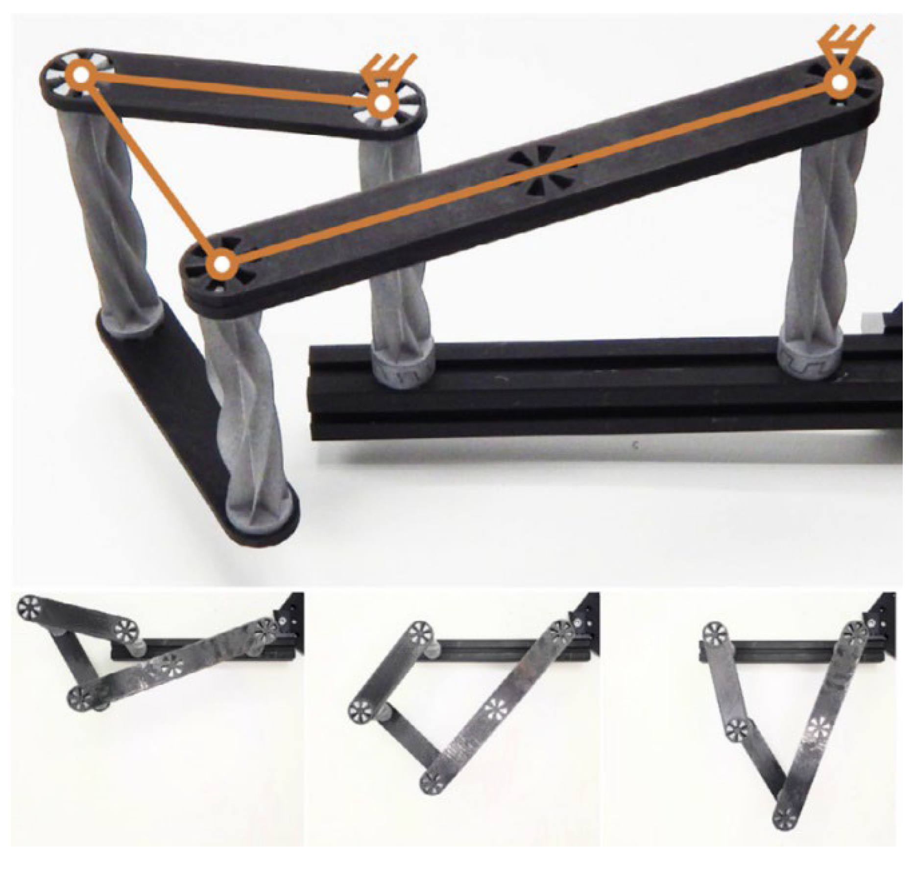
Figure 42.
Double spherical 6R connecting rod [104].
Figure 42.
Double spherical 6R connecting rod [104].

Figure 43.
Bearings and their components [106].
Figure 43.
Bearings and their components [106].
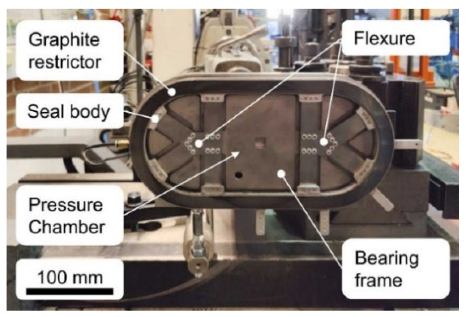
Figure 44.
Ansys 3-D model of 3-coil AMB [107].
Figure 44.
Ansys 3-D model of 3-coil AMB [107].
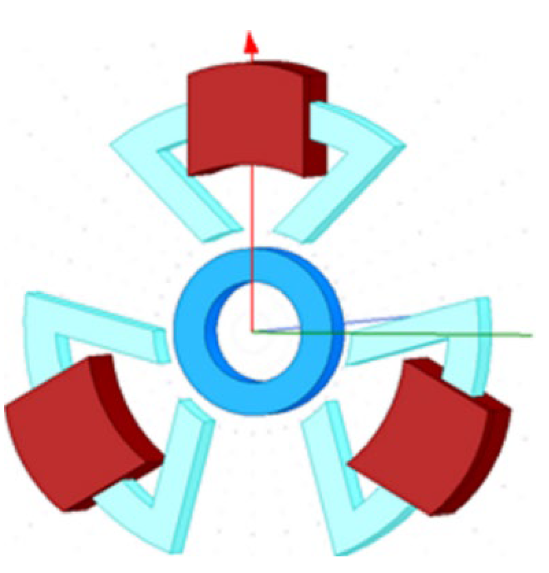
Figure 45.
Hybrid Ceramic Ball Bearing [108].
Figure 45.
Hybrid Ceramic Ball Bearing [108].
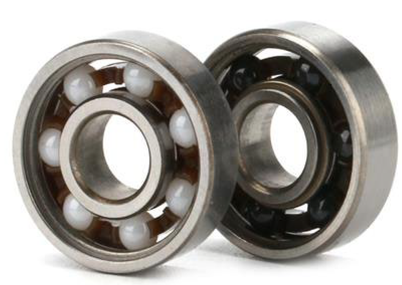
Figure 46.
Conventional indexing mechanism. (a) A curved surface, (b) parallel, (c) cylindrical, (d) Geneva exterior, and (e) Geneva interior [114].
Figure 46.
Conventional indexing mechanism. (a) A curved surface, (b) parallel, (c) cylindrical, (d) Geneva exterior, and (e) Geneva interior [114].
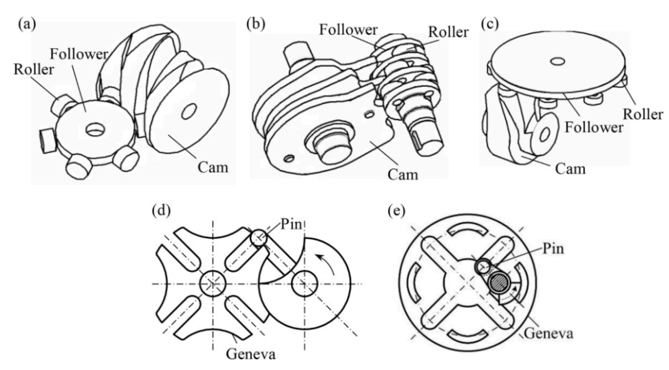
Figure 47.
The coaxial cam-linkage indexing mechanism. (a) CAD model, (b) Exploded view, and (c) Schematic diagrams [114].
Figure 47.
The coaxial cam-linkage indexing mechanism. (a) CAD model, (b) Exploded view, and (c) Schematic diagrams [114].
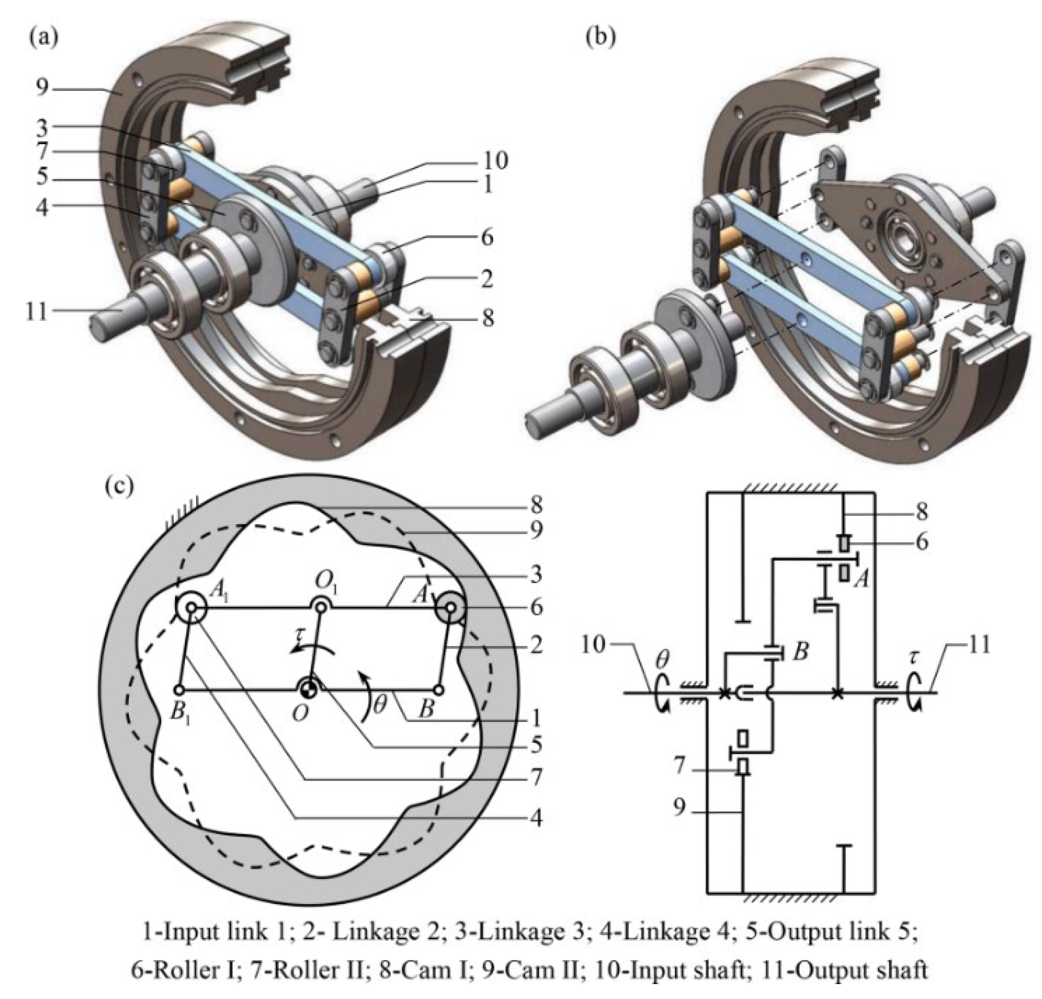
Figure 48.
Schematic diagram of the mechanism for transforming continuous circular motion into intermittent circular motion [115].
Figure 48.
Schematic diagram of the mechanism for transforming continuous circular motion into intermittent circular motion [115].
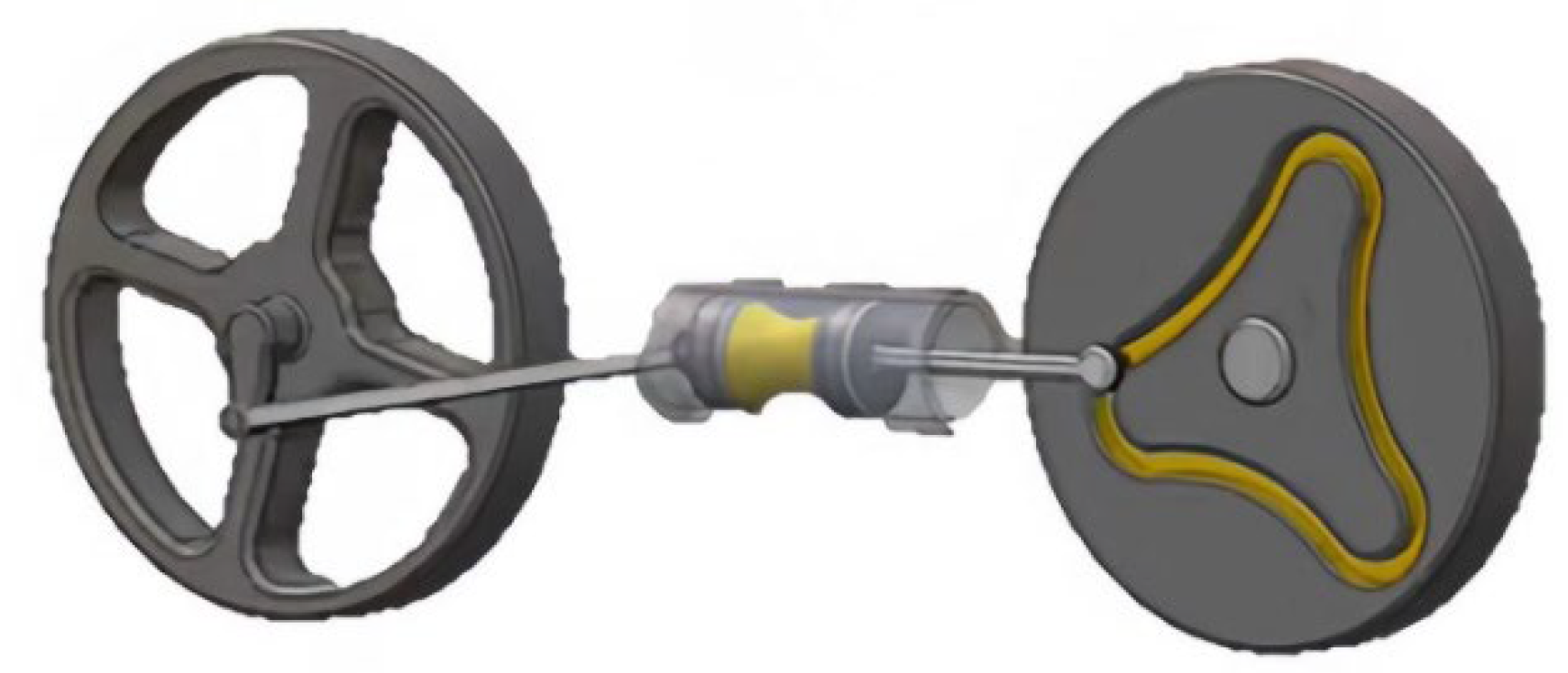
Figure 49.
Schematic diagram of crank and groove wheel drive mechanism [115].
Figure 49.
Schematic diagram of crank and groove wheel drive mechanism [115].
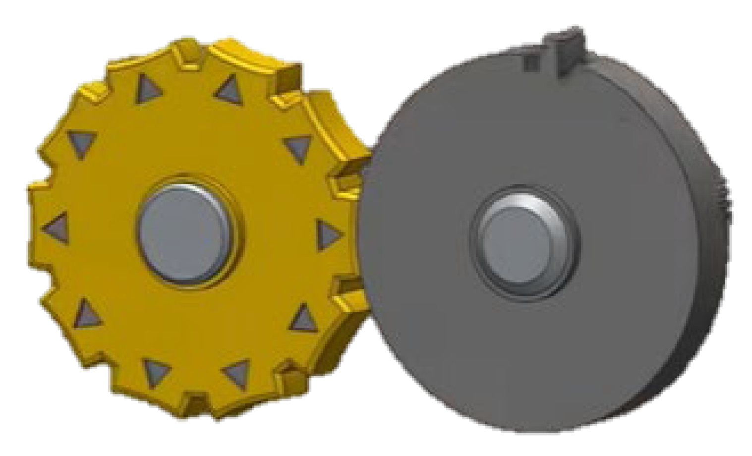
Figure 50.
Eccentric wheel spiral intermittent mechanism [116].
Figure 50.
Eccentric wheel spiral intermittent mechanism [116].
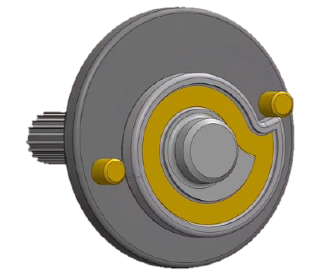
Figure 51.
Ball screw transmission mechanism [117].
Figure 51.
Ball screw transmission mechanism [117].
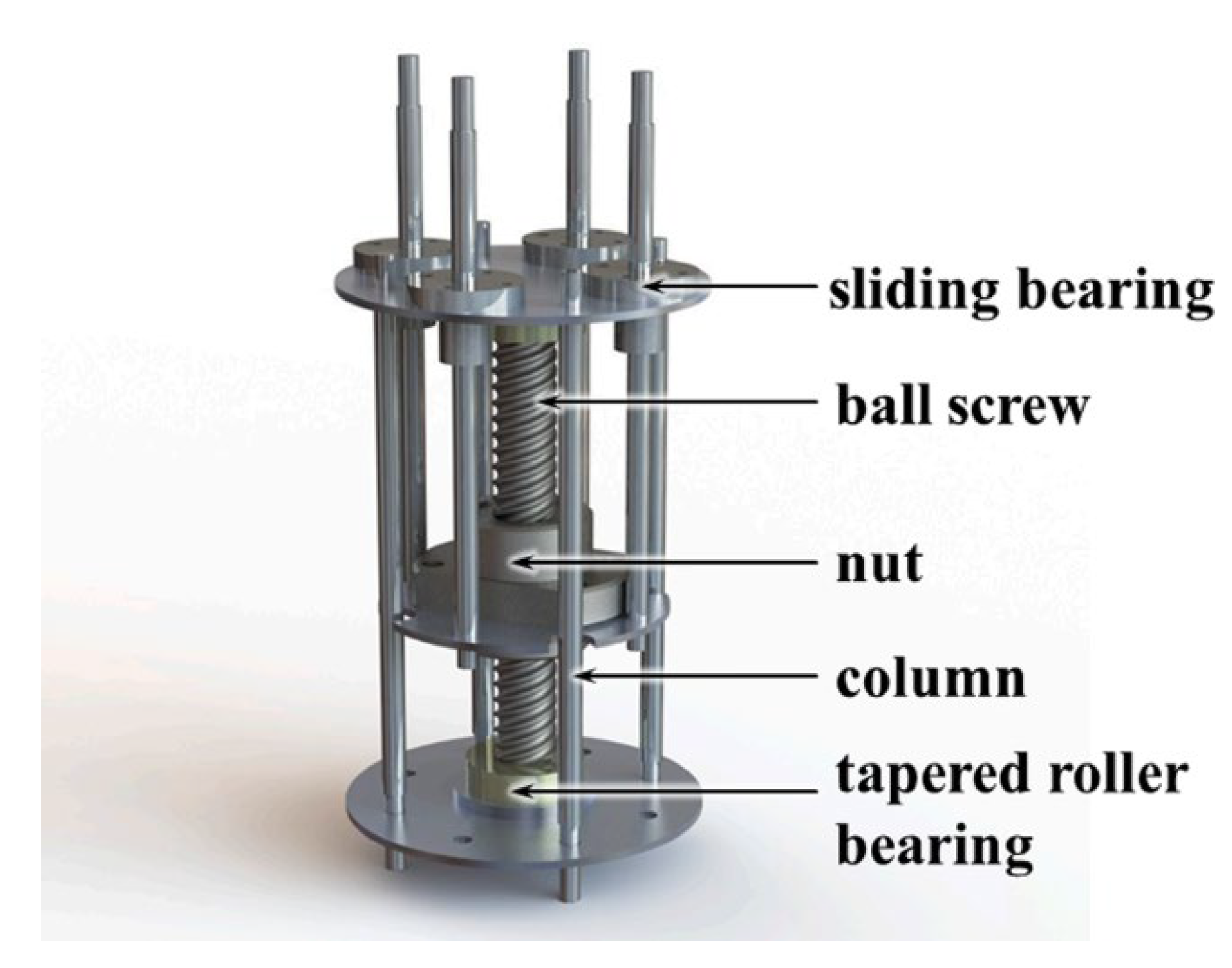
Figure 52.
Structure of planetary ball screw [119].
Figure 52.
Structure of planetary ball screw [119].
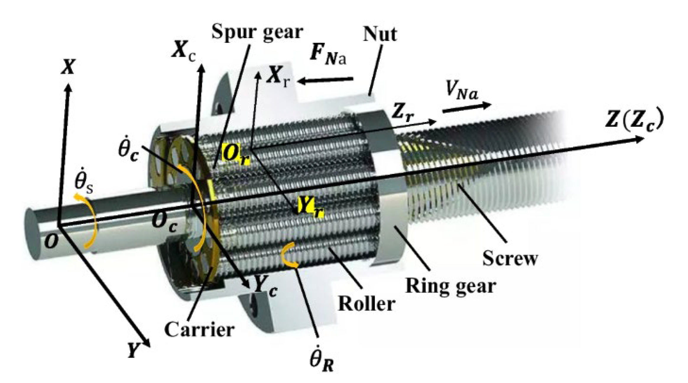
Figure 53.
Nut-driven static pressure screw feeding system [120].
Figure 53.
Nut-driven static pressure screw feeding system [120].
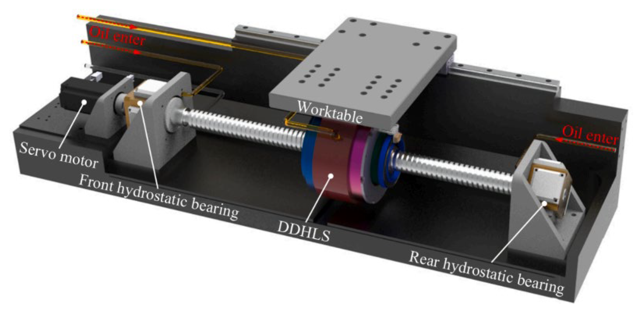
Figure 54.
Main structure of EHSA [121].
Figure 54.
Main structure of EHSA [121].
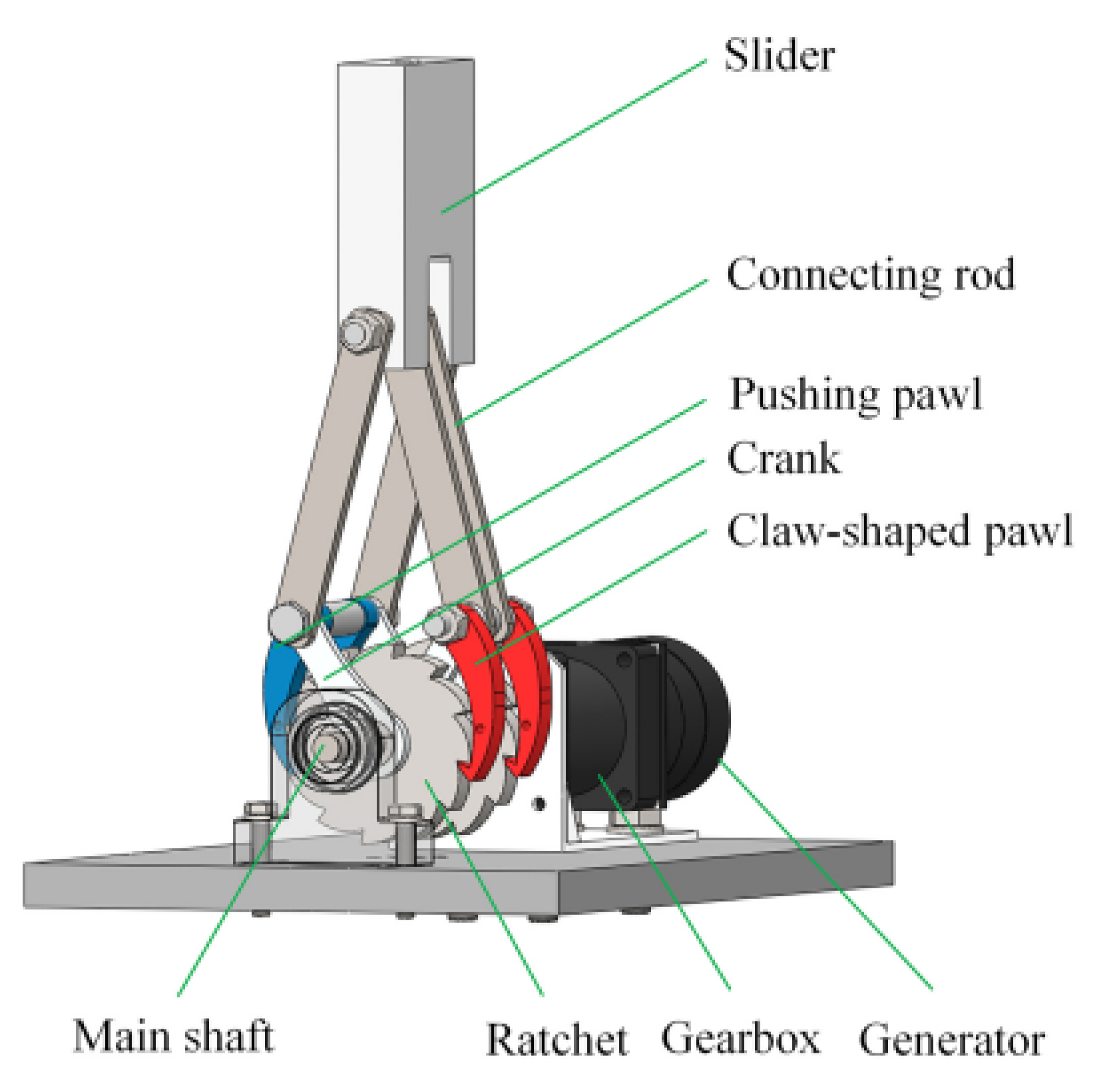
Figure 55.
WEC platform with MLS in PTO cylinder [122].
Figure 55.
WEC platform with MLS in PTO cylinder [122].
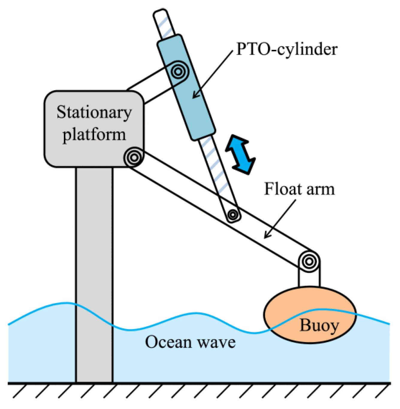
Figure 56.
Rack mechanism of serial coupling [123].
Figure 56.
Rack mechanism of serial coupling [123].
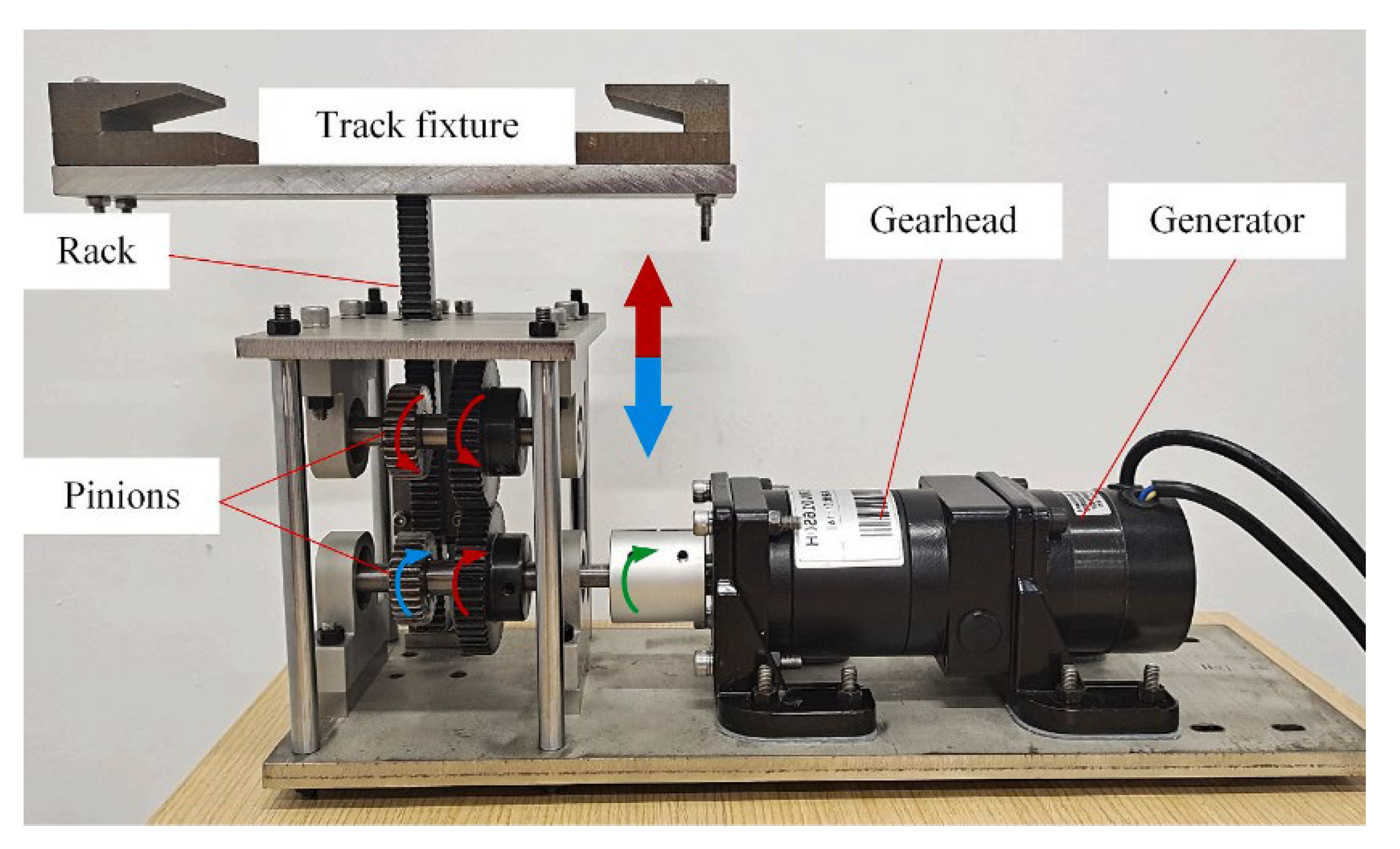
Figure 57.
Working process of mechanical transmission [124].
Figure 57.
Working process of mechanical transmission [124].
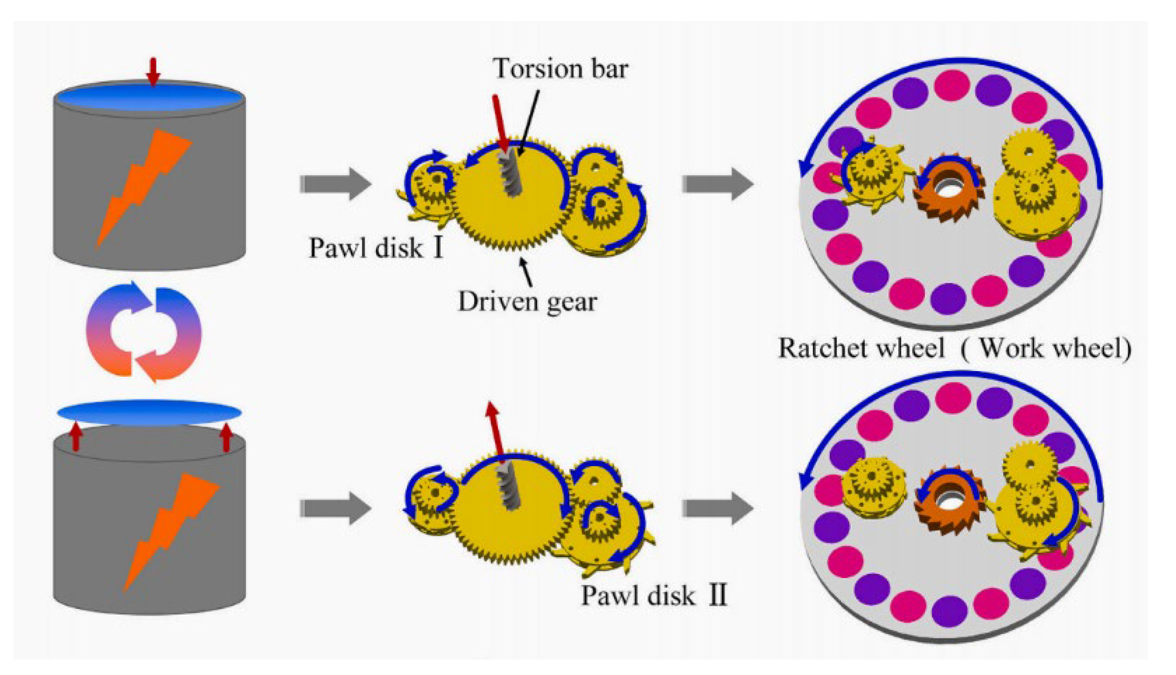
Figure 58.
Finger mechanism driven by TCP actuator [125].
Figure 58.
Finger mechanism driven by TCP actuator [125].
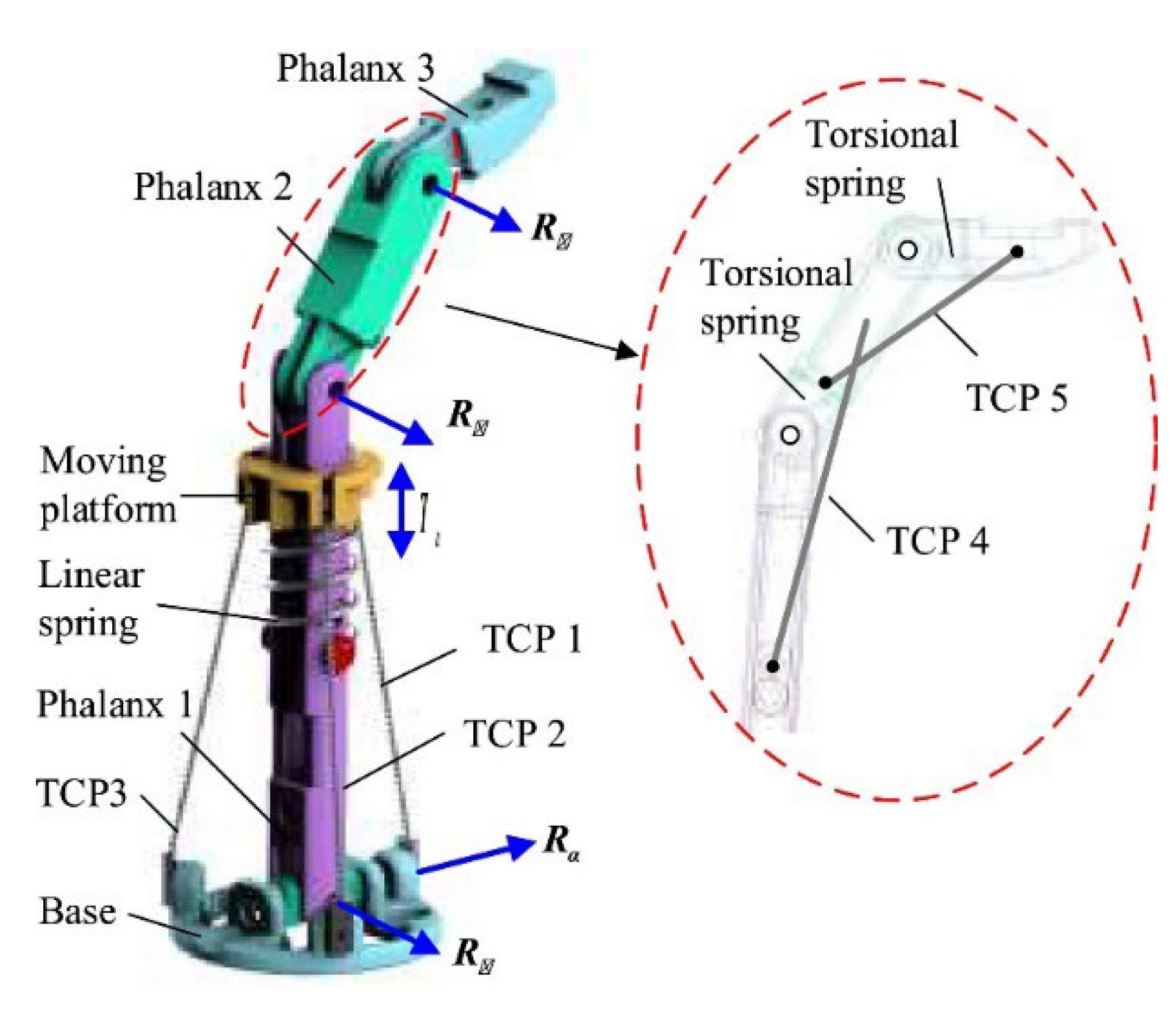
Figure 59.
Prototype structure of SMM [126].
Figure 59.
Prototype structure of SMM [126].
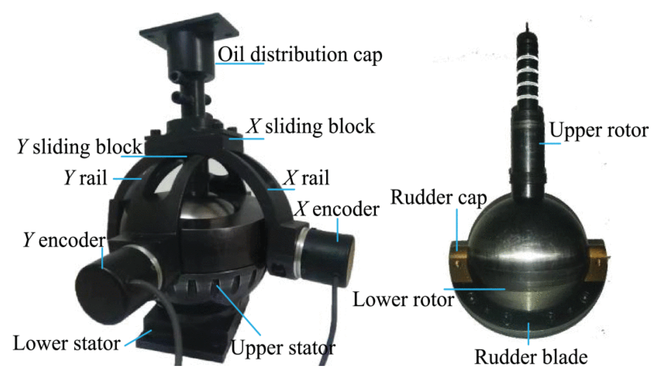
Figure 60.
Driven Branch Chain and Combined Shaft [127].
Figure 60.
Driven Branch Chain and Combined Shaft [127].
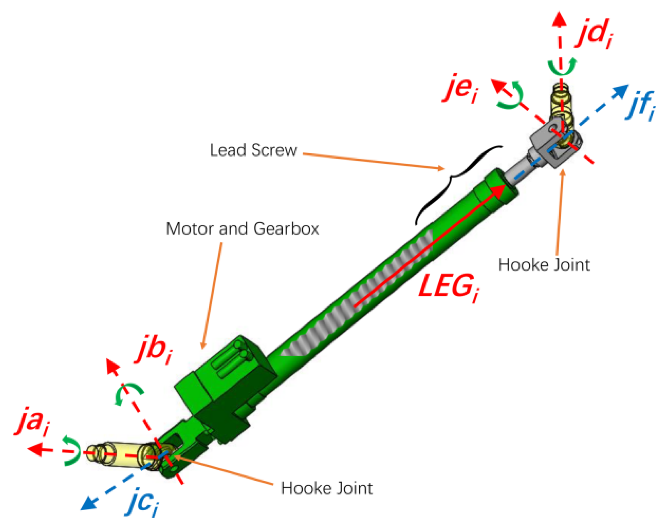
Figure 61.
The three degrees of freedom tensioned integral structure with the mechanism proposed: (a) assembled view and (b) unassembled unfolded view [128].
Figure 61.
The three degrees of freedom tensioned integral structure with the mechanism proposed: (a) assembled view and (b) unassembled unfolded view [128].
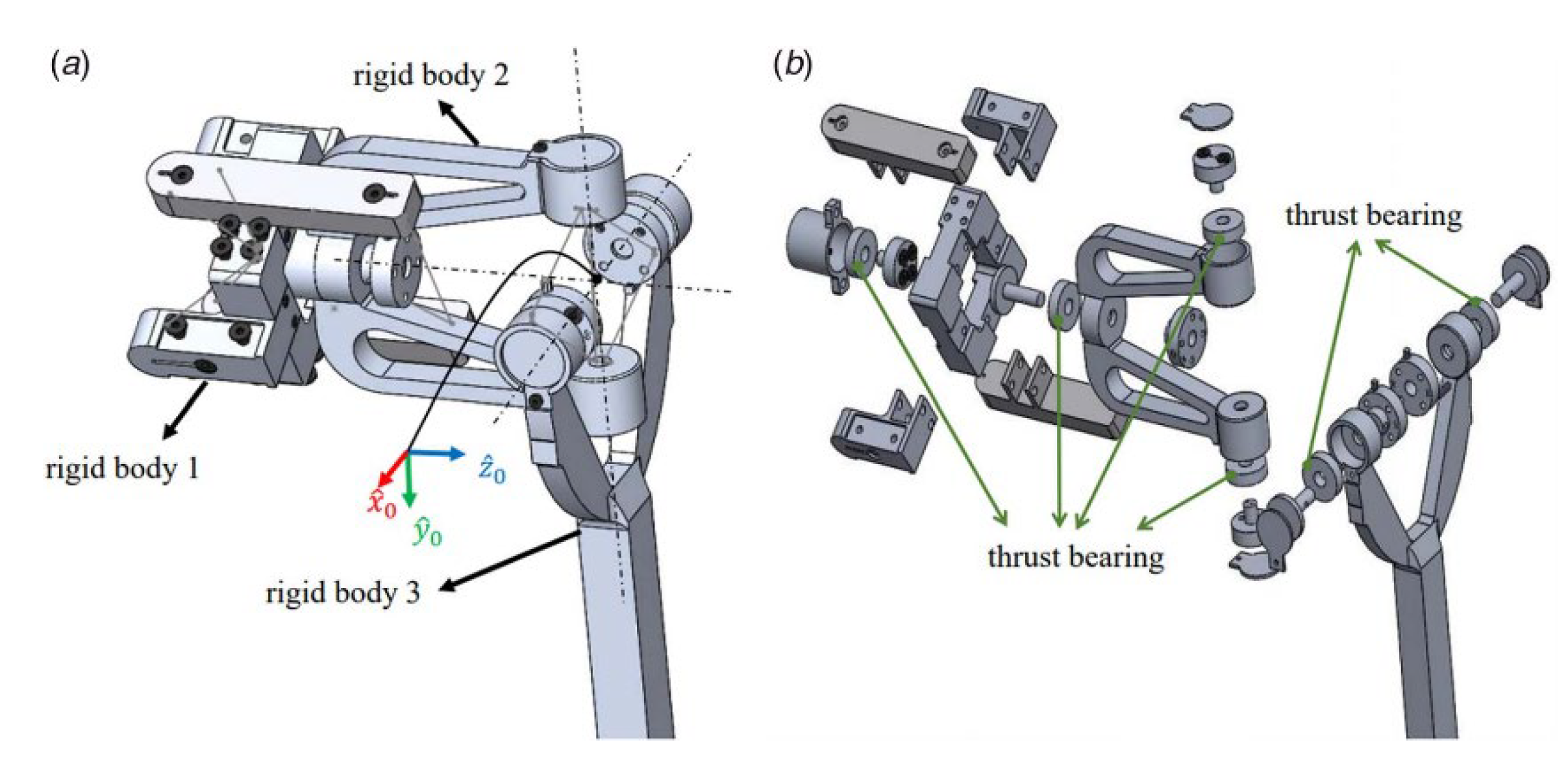
Figure 62.
Human Fingers and Nomenclature: Anatomy of Human Fingers, showing phalanges and interphalangeal joints. The phalanges and interphalangeal joints in the B development prototype [129].
Figure 62.
Human Fingers and Nomenclature: Anatomy of Human Fingers, showing phalanges and interphalangeal joints. The phalanges and interphalangeal joints in the B development prototype [129].
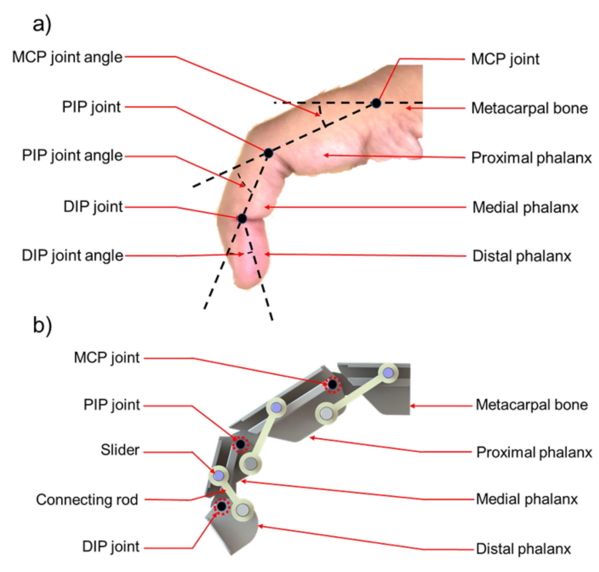
Figure 63.
The snapshots of reference group (a) and assistance group (b) [130].
Figure 63.
The snapshots of reference group (a) and assistance group (b) [130].
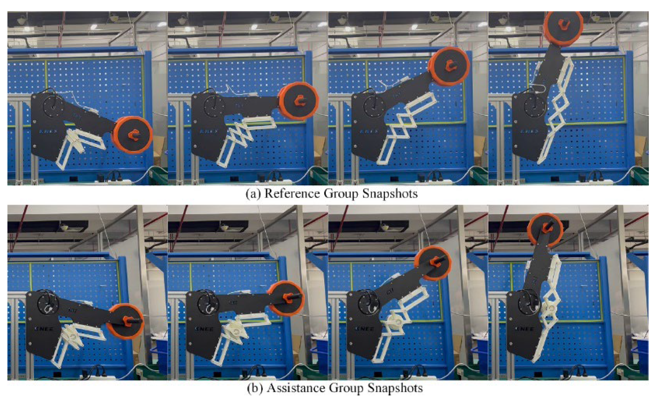
Figure 64.
Three-dimensional model of non-circular gear five bar mechanism [131]. (1. Sun gear; 2 Planetary Wheel I; 3. Rod 1; 4. Rod 2; 5. actuator; 6. Rod 3; 7. Planetary Wheel II).
Figure 64.
Three-dimensional model of non-circular gear five bar mechanism [131]. (1. Sun gear; 2 Planetary Wheel I; 3. Rod 1; 4. Rod 2; 5. actuator; 6. Rod 3; 7. Planetary Wheel II).
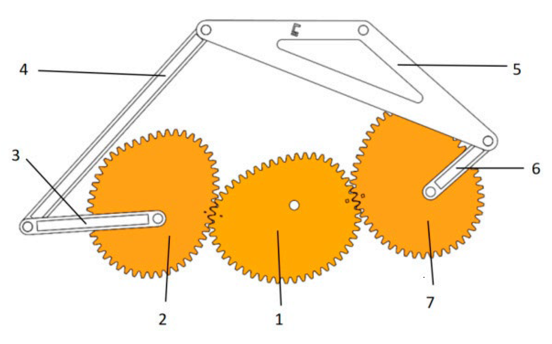
Figure 65.
Design steps of rotary transmission mechanism [132].
Figure 65.
Design steps of rotary transmission mechanism [132].
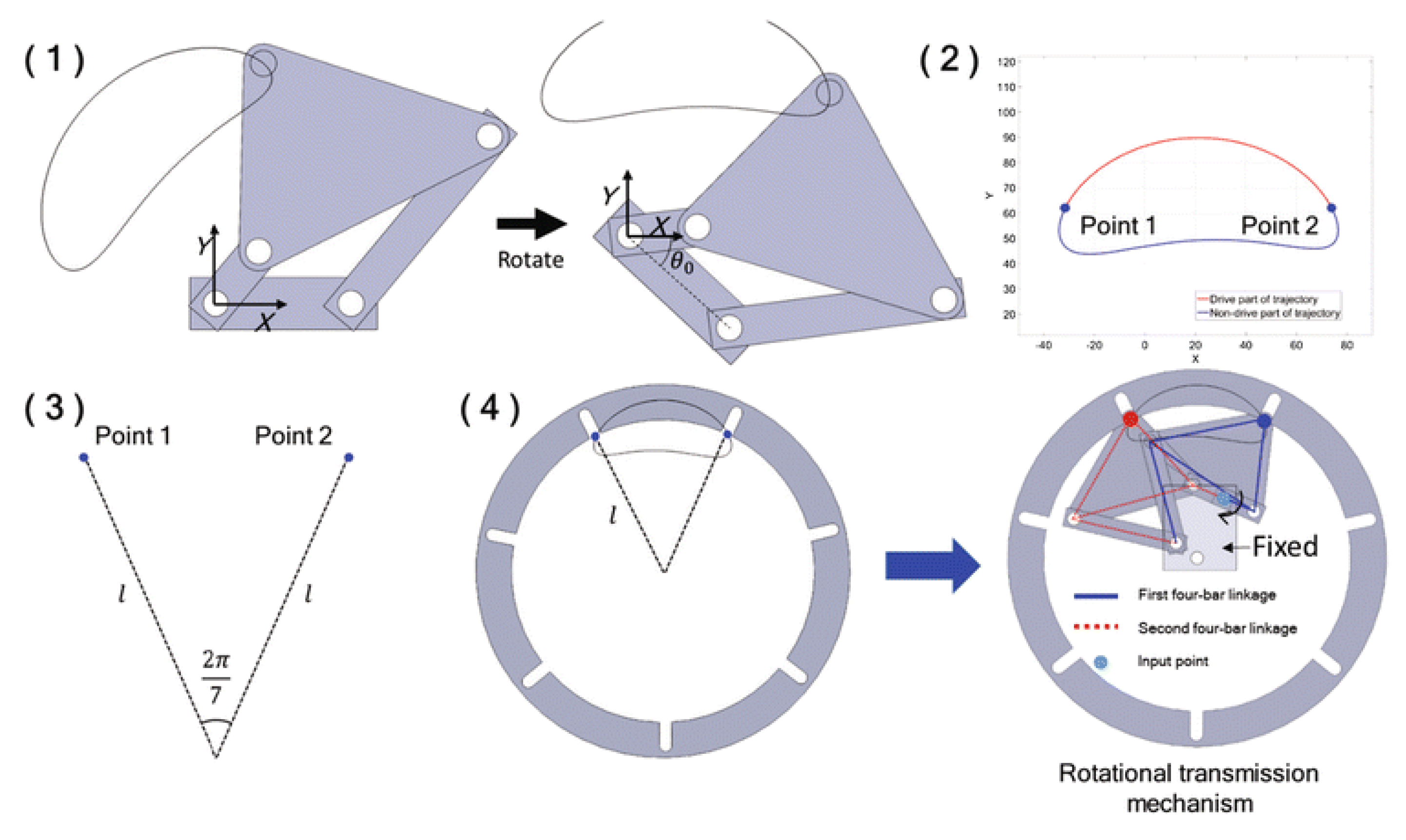
Figure 66.
RTM prototype for automatic tool changing device. Position during counterclockwise movement (1-6) [132].
Figure 66.
RTM prototype for automatic tool changing device. Position during counterclockwise movement (1-6) [132].

Figure 67.
Schematic diagram of cam five bar mechanism: composed of linkage mechanism 1-2-3-4 and cam mechanism 5-6, where rod 1 is a rotating disc, rod 2 is a rocker arm, and rod 3 is a linkage mechanism. Output component 4 consists of a bellows assembly and a circular guide rail [133].
Figure 67.
Schematic diagram of cam five bar mechanism: composed of linkage mechanism 1-2-3-4 and cam mechanism 5-6, where rod 1 is a rotating disc, rod 2 is a rocker arm, and rod 3 is a linkage mechanism. Output component 4 consists of a bellows assembly and a circular guide rail [133].

Figure 68.
Production line working diagram [133].
Figure 68.
Production line working diagram [133].
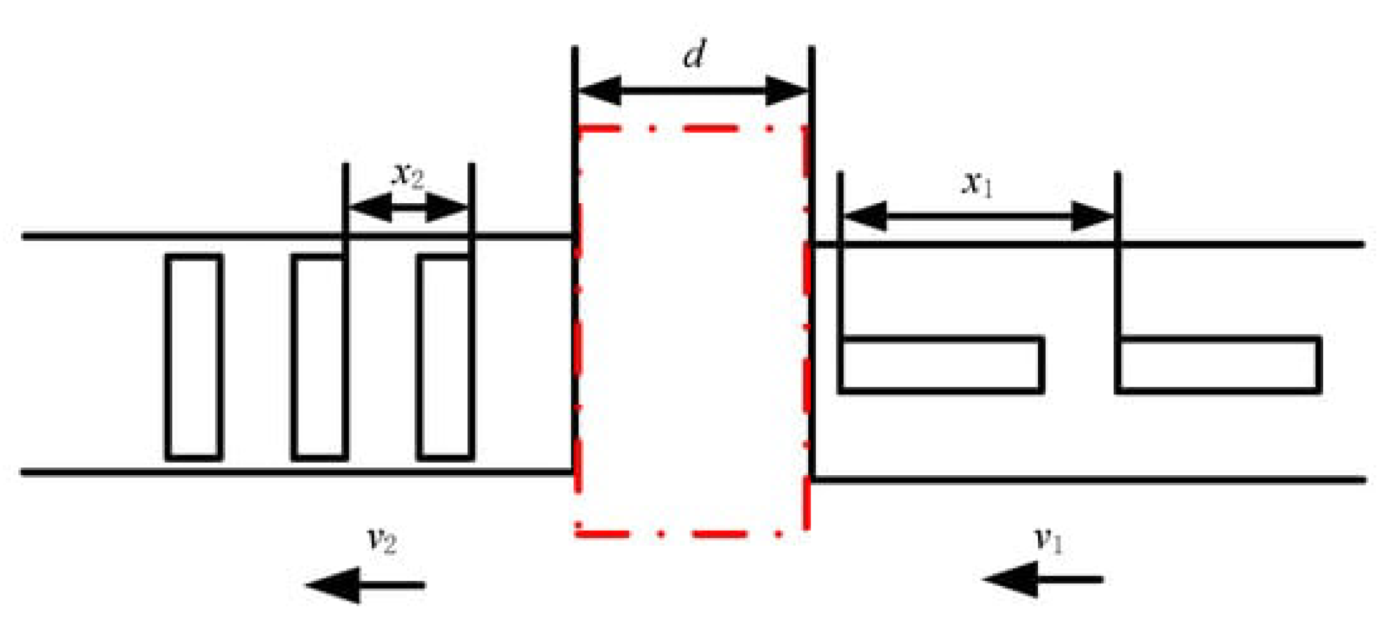
Figure 69.
7-DOF assembly robot [134].
Figure 69.
7-DOF assembly robot [134].
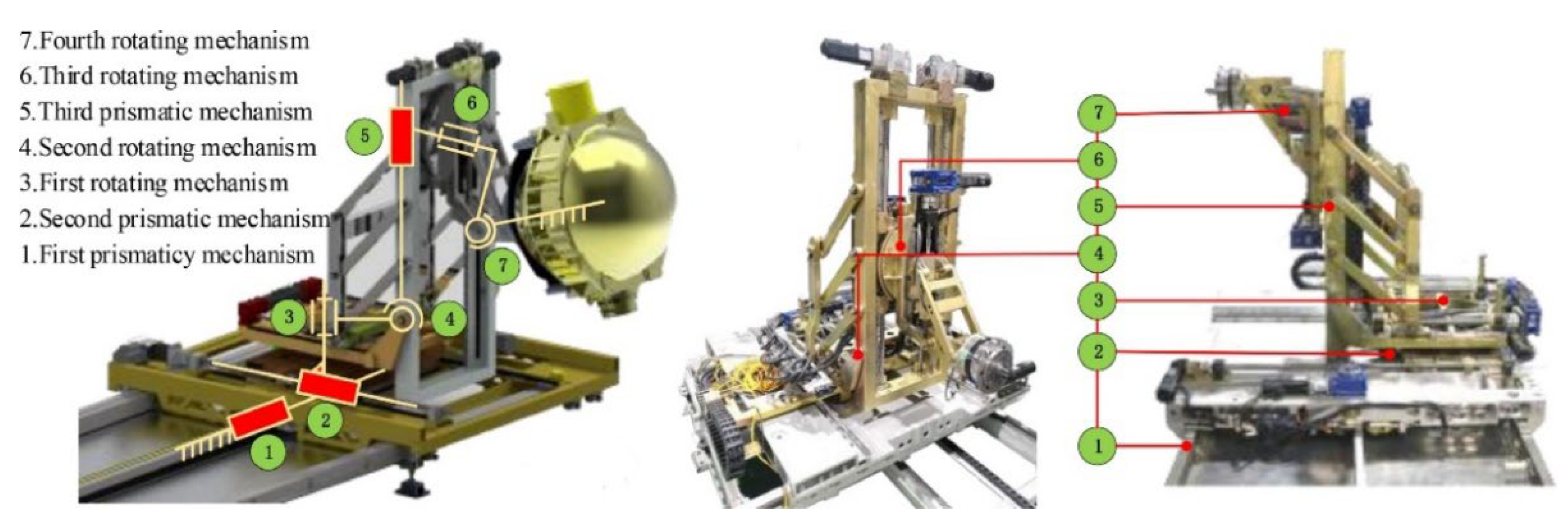
Figure 70.
Schematic diagram of seedling picking mechanism: 1. Planetary gear; 2. Intermediate gear; 3. Sun gear; 4. Seedling tray; 5. Tray seedling delivery mechanism; 6. Cam; 7. Linkage mechanism; 8. Roller [137].
Figure 70.
Schematic diagram of seedling picking mechanism: 1. Planetary gear; 2. Intermediate gear; 3. Sun gear; 4. Seedling tray; 5. Tray seedling delivery mechanism; 6. Cam; 7. Linkage mechanism; 8. Roller [137].
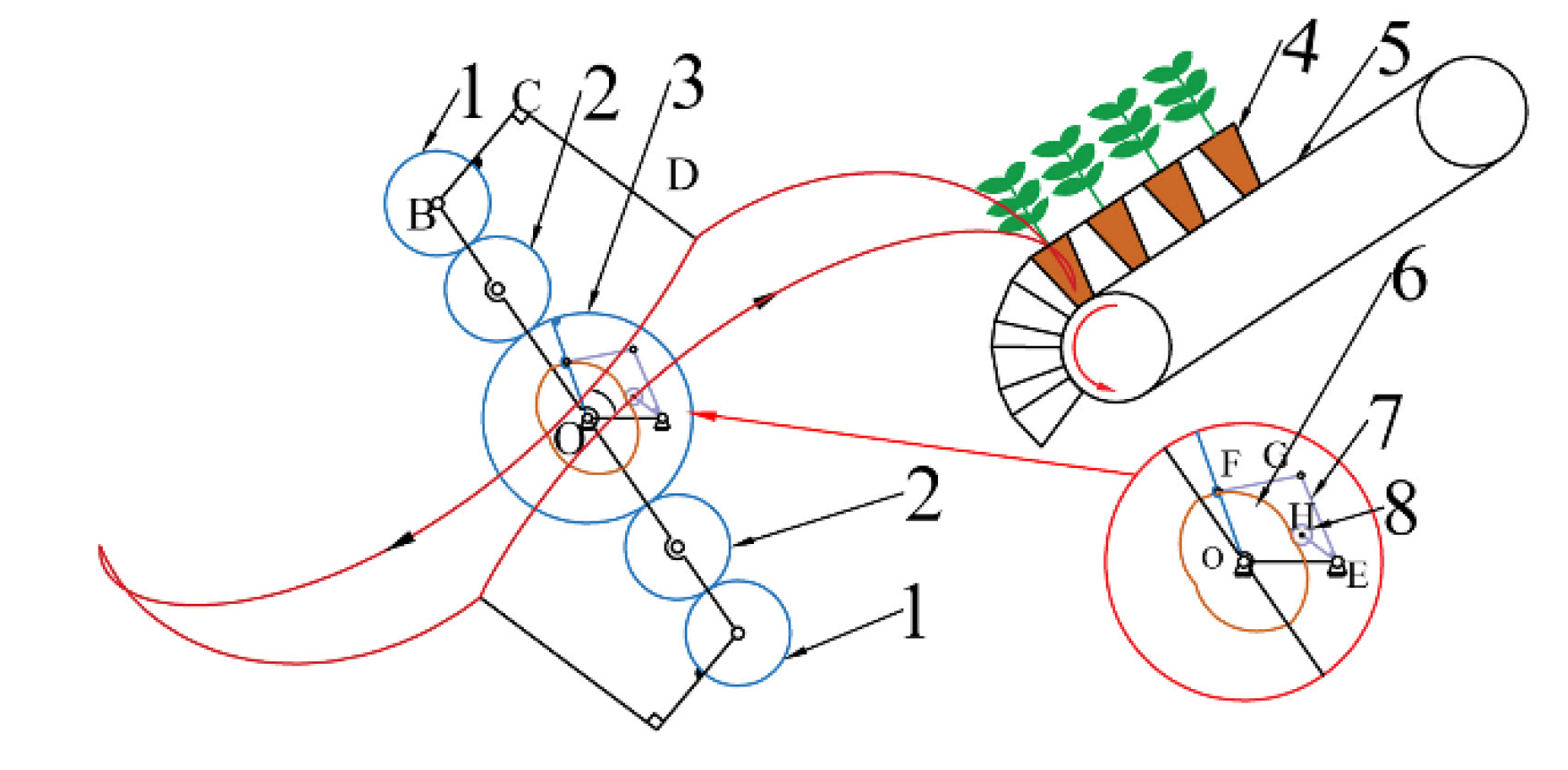
Figure 71.
Cam connecting rod planetary gear system seedling picking mechanism: 1. Left housing; 2. Planetary gears; 3. Intermediate gear; 4. Sun gear; 5. Cam; 6. Linkage mechanism; 7. Roller; 8. Seedling picking arm; 9. Right housing; 10. Rack mounting board; 11. Input shaft [137].
Figure 71.
Cam connecting rod planetary gear system seedling picking mechanism: 1. Left housing; 2. Planetary gears; 3. Intermediate gear; 4. Sun gear; 5. Cam; 6. Linkage mechanism; 7. Roller; 8. Seedling picking arm; 9. Right housing; 10. Rack mounting board; 11. Input shaft [137].
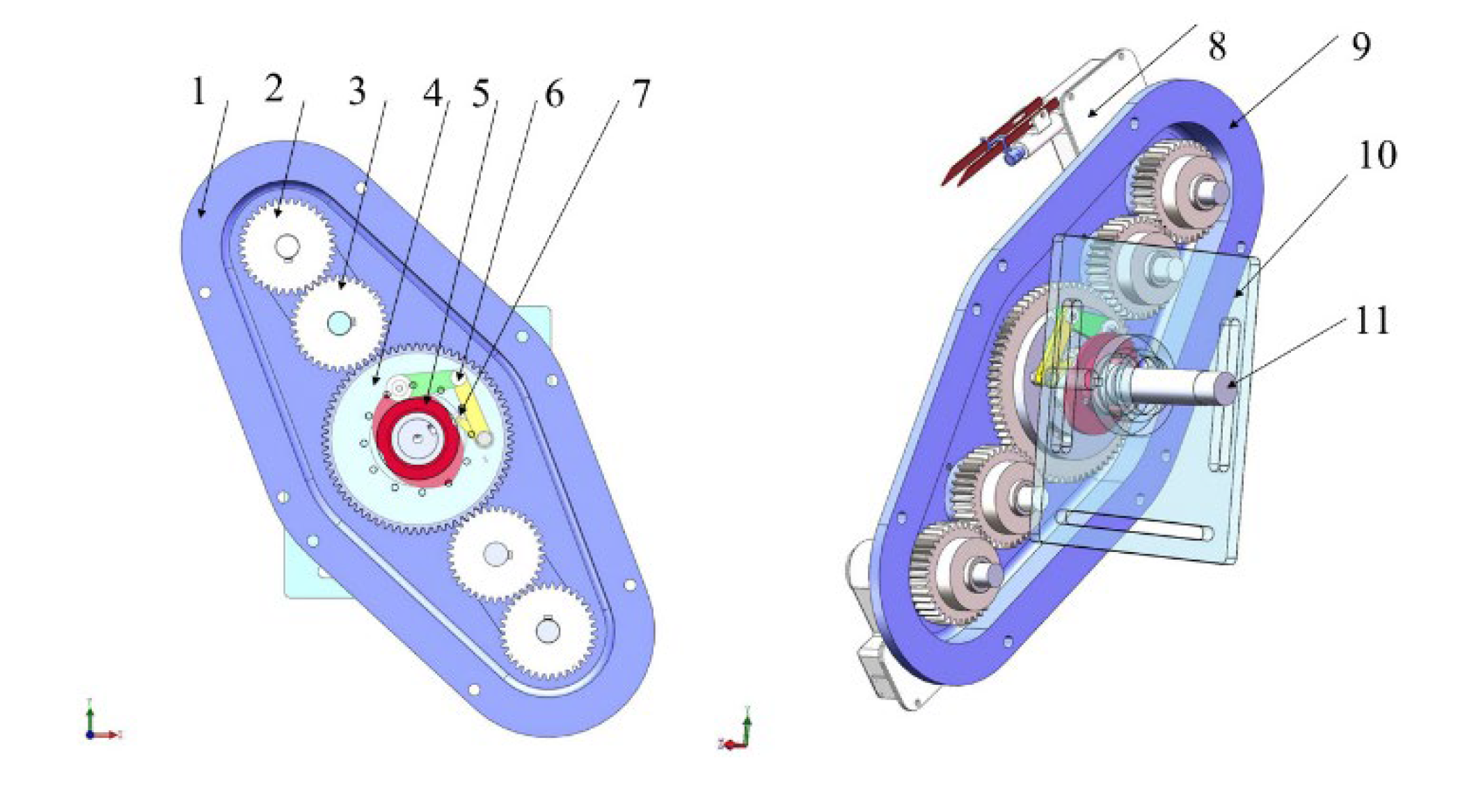
Figure 72.
Variable pitch biomimetic propeller [138].
Figure 72.
Variable pitch biomimetic propeller [138].
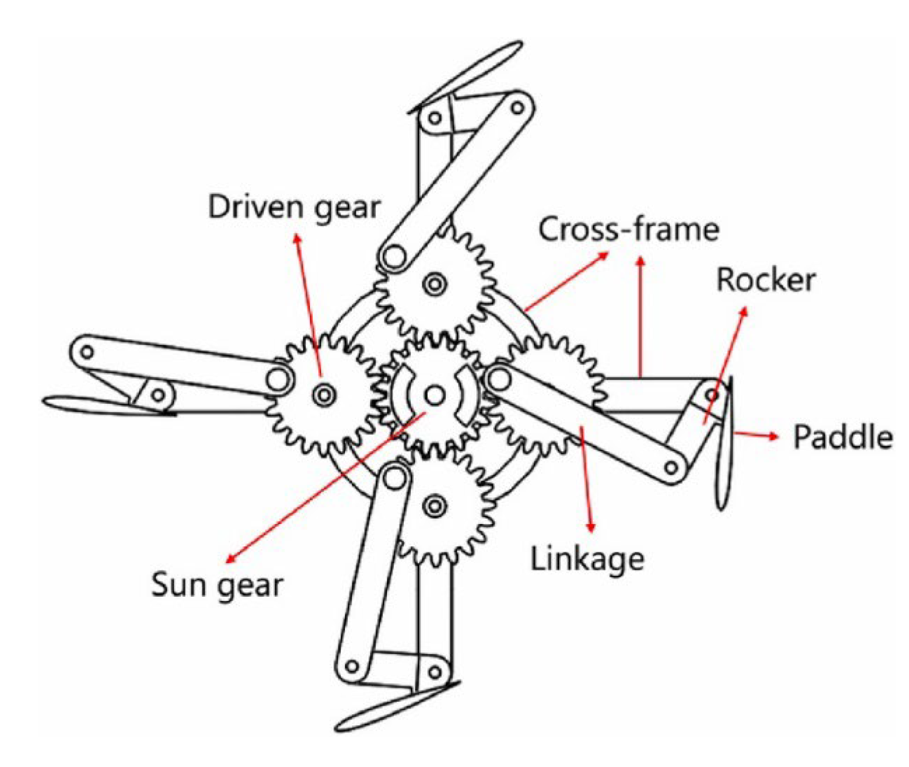
Figure 73.
CAD model and schematic diagram of RV reducer (1-sun gear); 2-planetary gear; 3-crankshaft; 4-pin gear; 5 needle housing; 6-cyclic gear; 7-carrier; 8-output disk) [139].
Figure 73.
CAD model and schematic diagram of RV reducer (1-sun gear); 2-planetary gear; 3-crankshaft; 4-pin gear; 5 needle housing; 6-cyclic gear; 7-carrier; 8-output disk) [139].
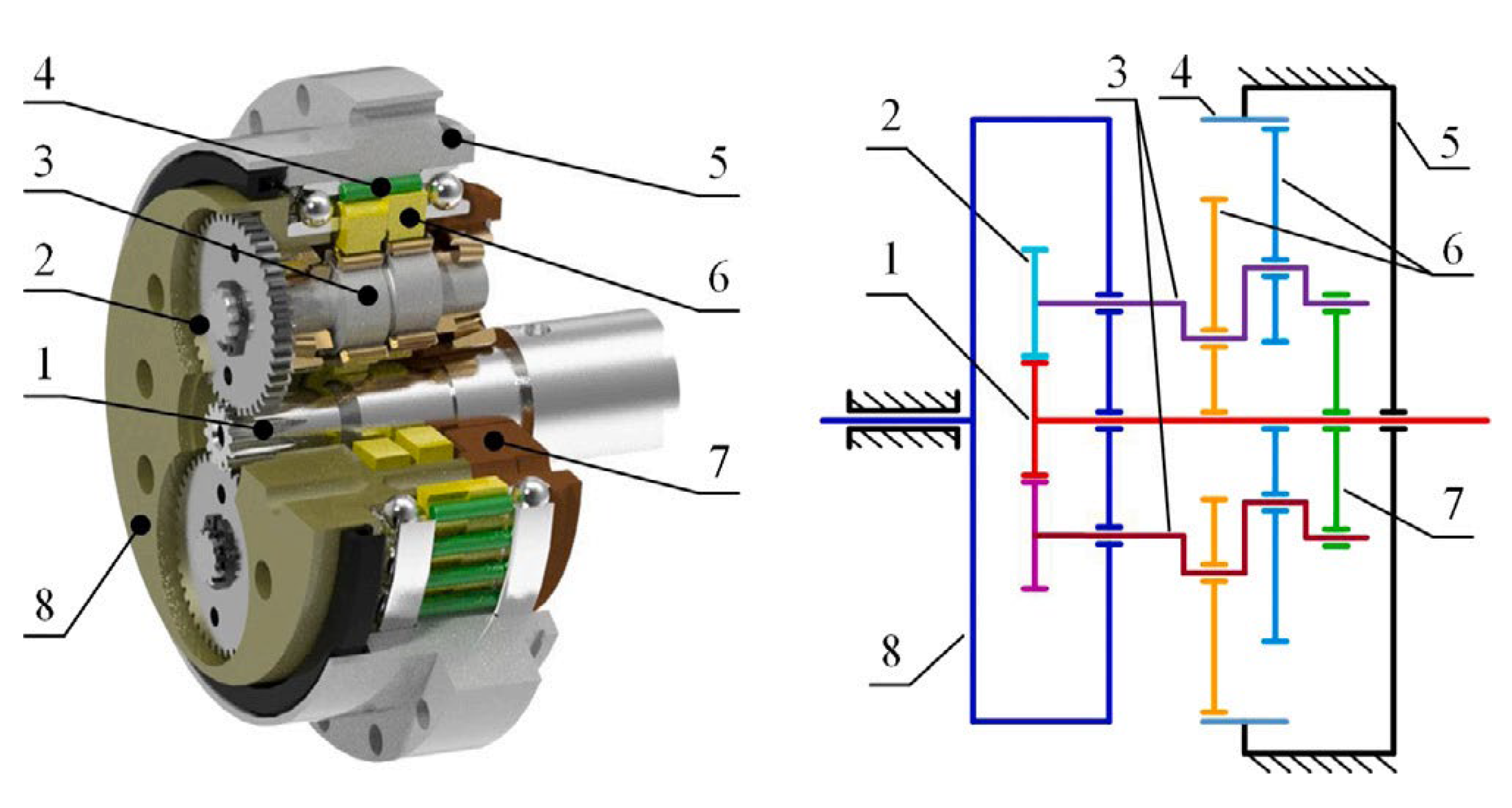
Figure 74.
Structural diagram of two-stage cycloidal reducer:1-input shaft of reducer, 2-first stage cycloidal disc, 3-Shell roller of fixed ring gear of first stage, 4-central disc, 5-second stage cycloidal disc, 6-ring gear [140].
Figure 74.
Structural diagram of two-stage cycloidal reducer:1-input shaft of reducer, 2-first stage cycloidal disc, 3-Shell roller of fixed ring gear of first stage, 4-central disc, 5-second stage cycloidal disc, 6-ring gear [140].
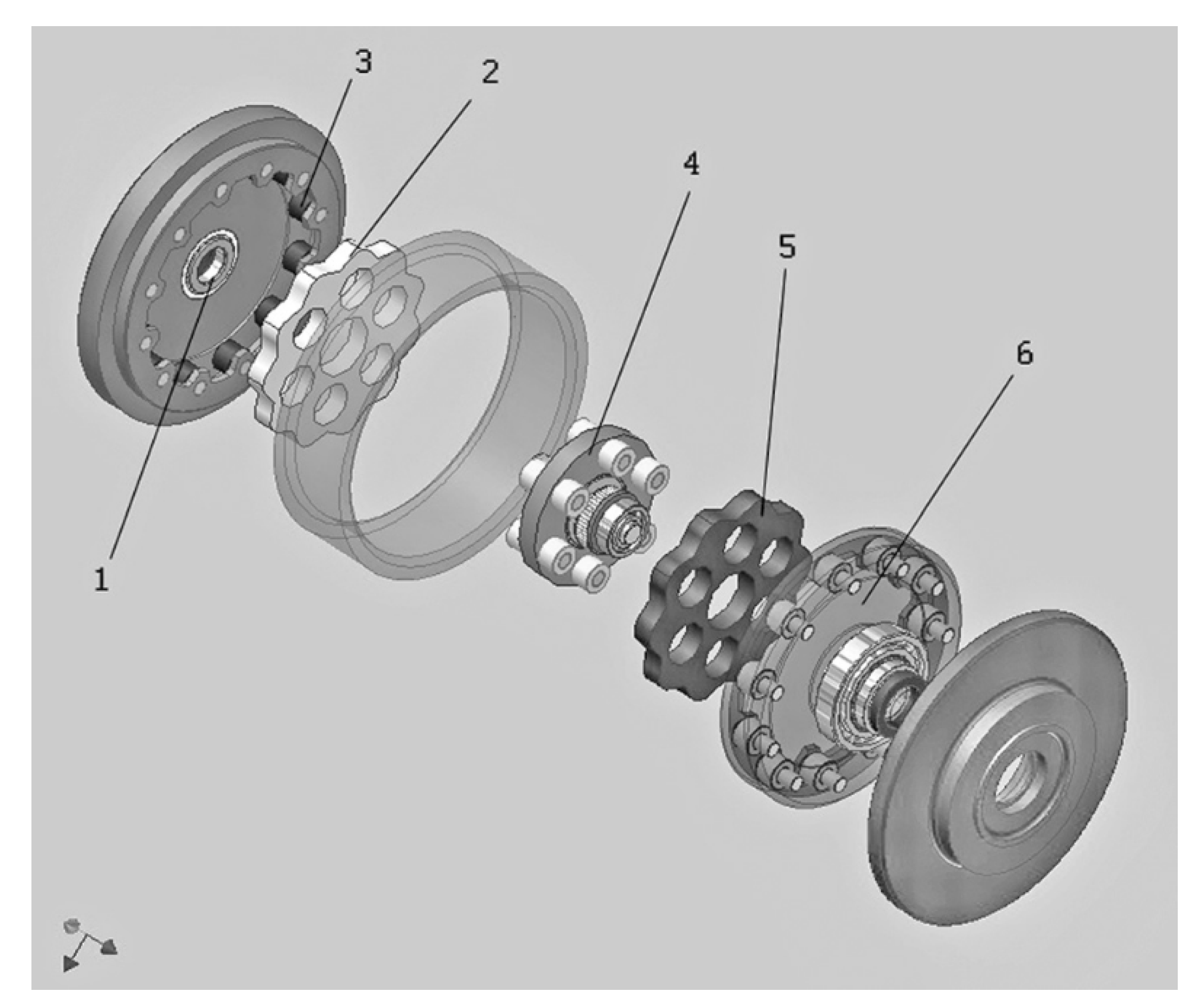
Figure 75.
Transmission principles and structural design of three different single-stage cycloidal pin reducers: (a) traditional cycloidal pin reducer, (b) precision cycloidal pin reducer (model: F4CF), (c) proposed new cycloidal pin reducer [141].
Figure 75.
Transmission principles and structural design of three different single-stage cycloidal pin reducers: (a) traditional cycloidal pin reducer, (b) precision cycloidal pin reducer (model: F4CF), (c) proposed new cycloidal pin reducer [141].
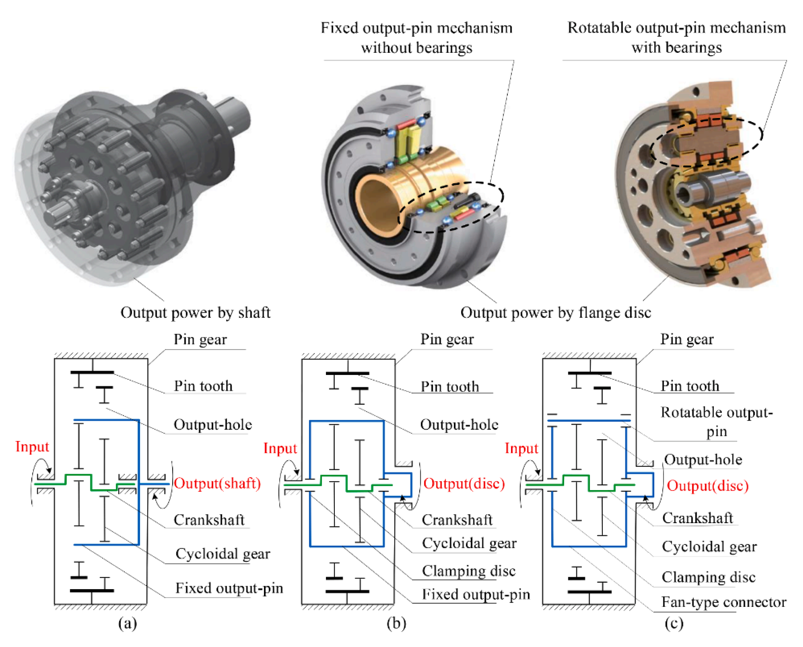
Figure 76.
The overall structure of the actuator integrated artificial knee joint [142].
Figure 76.
The overall structure of the actuator integrated artificial knee joint [142].
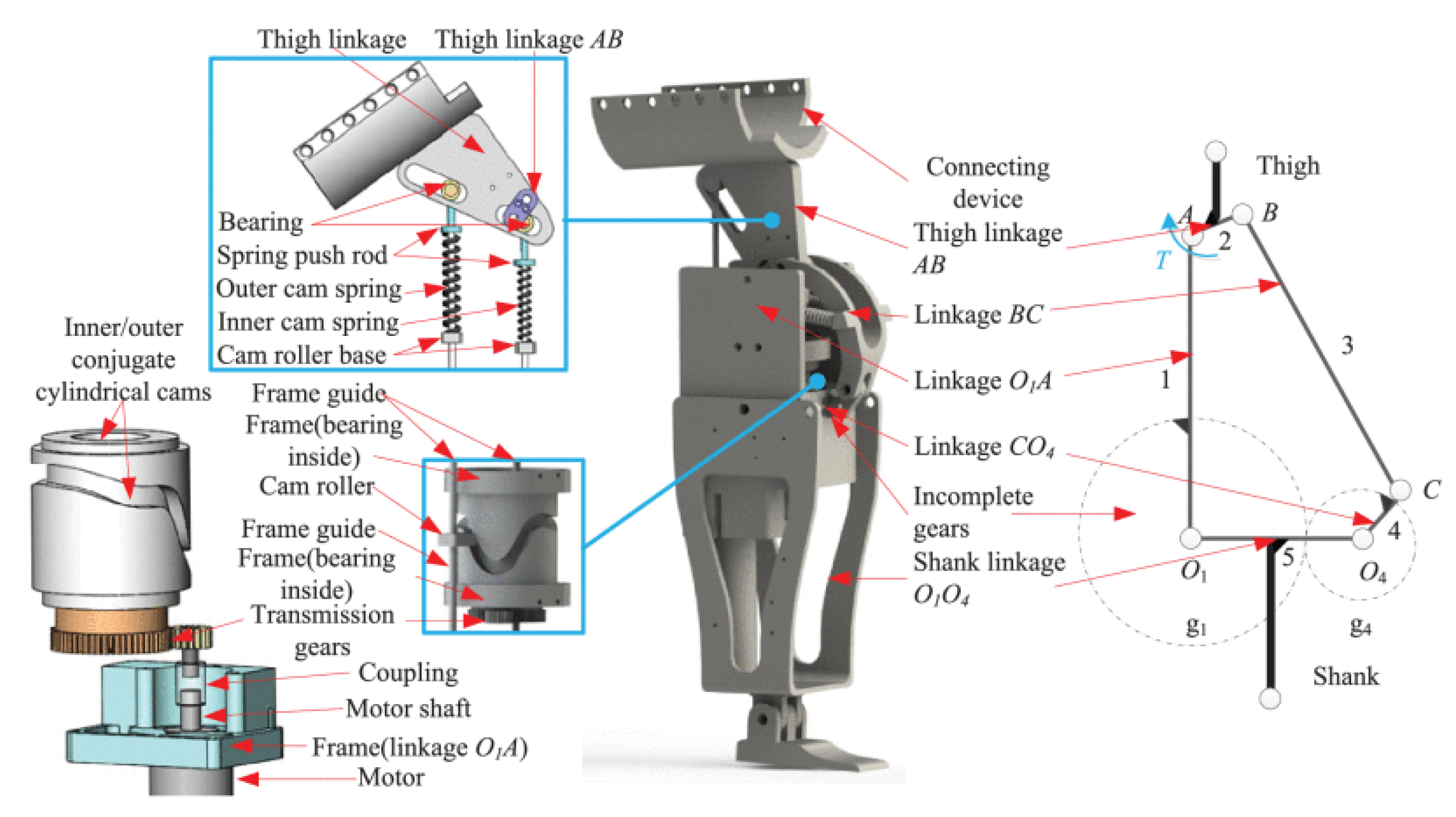
Figure 77.
(a) Principle explanation of bistable rotary actuator. A pair of single-axis FCDEA stretch each other through a rotating mechanism. (b) Schematic diagram of the rotating mechanism (c): Schematic diagrams of the left and right configurations. (d) Bistable rotating mechanism [143].
Figure 77.
(a) Principle explanation of bistable rotary actuator. A pair of single-axis FCDEA stretch each other through a rotating mechanism. (b) Schematic diagram of the rotating mechanism (c): Schematic diagrams of the left and right configurations. (d) Bistable rotating mechanism [143].
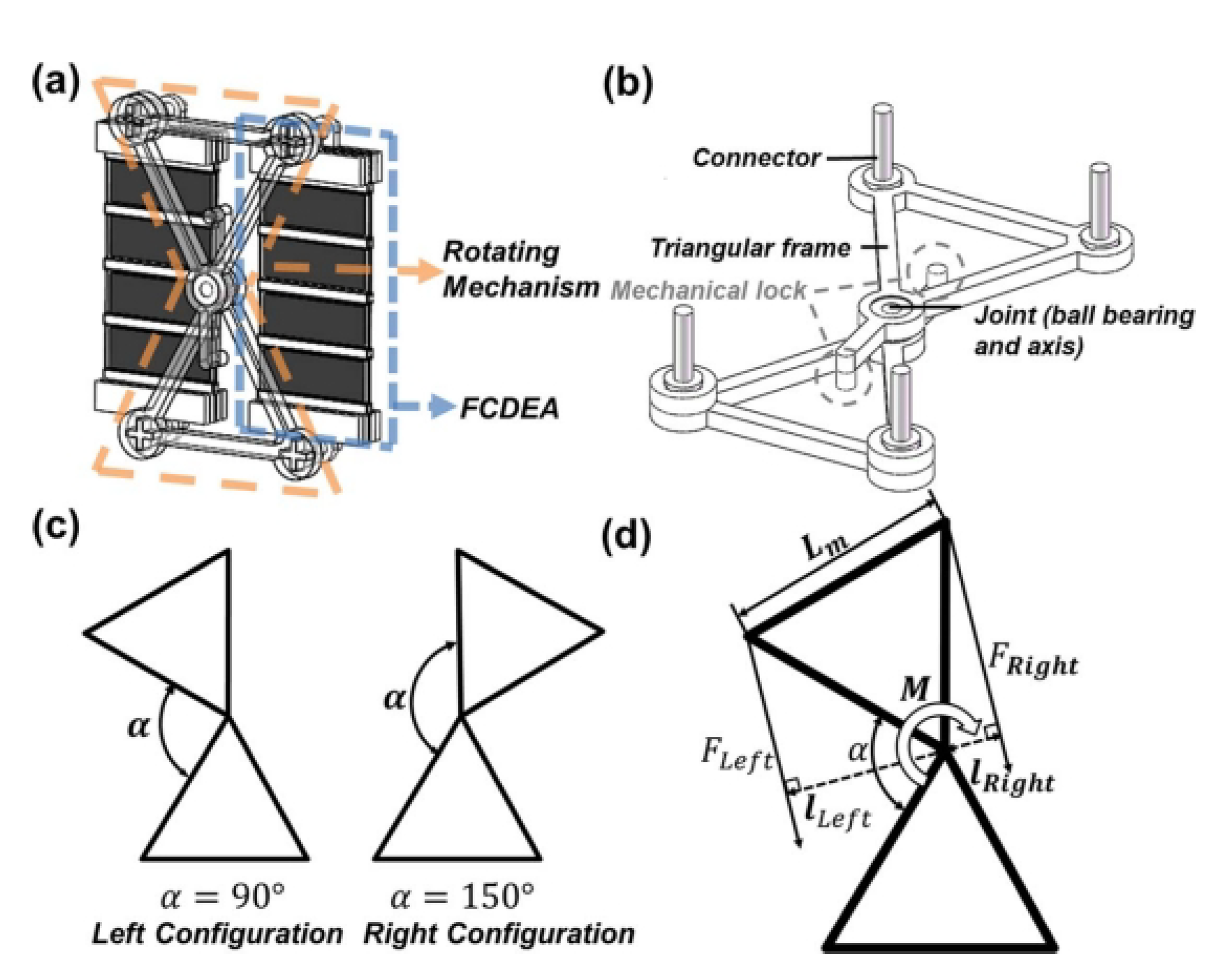
Figure 78.
TSNSA configuration: (a) open view, (b) sectional view, (c) front view, (d) three-dimensional view [144].
Figure 78.
TSNSA configuration: (a) open view, (b) sectional view, (c) front view, (d) three-dimensional view [144].
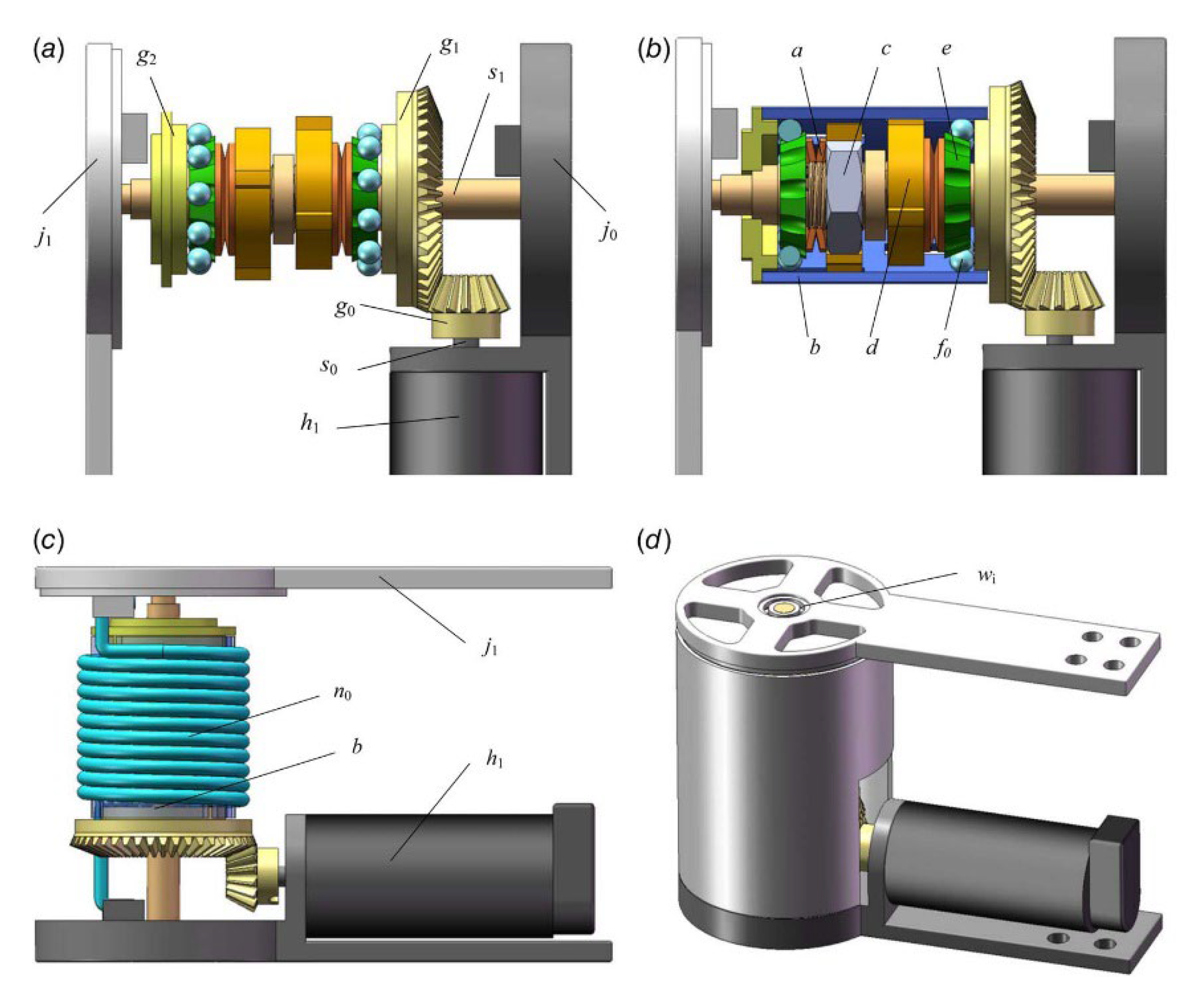
Figure 79.
Structure of SDS-VSA: 1. Positioning motor; 2. Harmonic reducer; 3. Output shaft; 4. Base; 5. Cam disc; 6. Roller retaining ring; 7. Disc-spring combination; 8. Harmonic reducer; 9. Rigid motor [145].
Figure 79.
Structure of SDS-VSA: 1. Positioning motor; 2. Harmonic reducer; 3. Output shaft; 4. Base; 5. Cam disc; 6. Roller retaining ring; 7. Disc-spring combination; 8. Harmonic reducer; 9. Rigid motor [145].
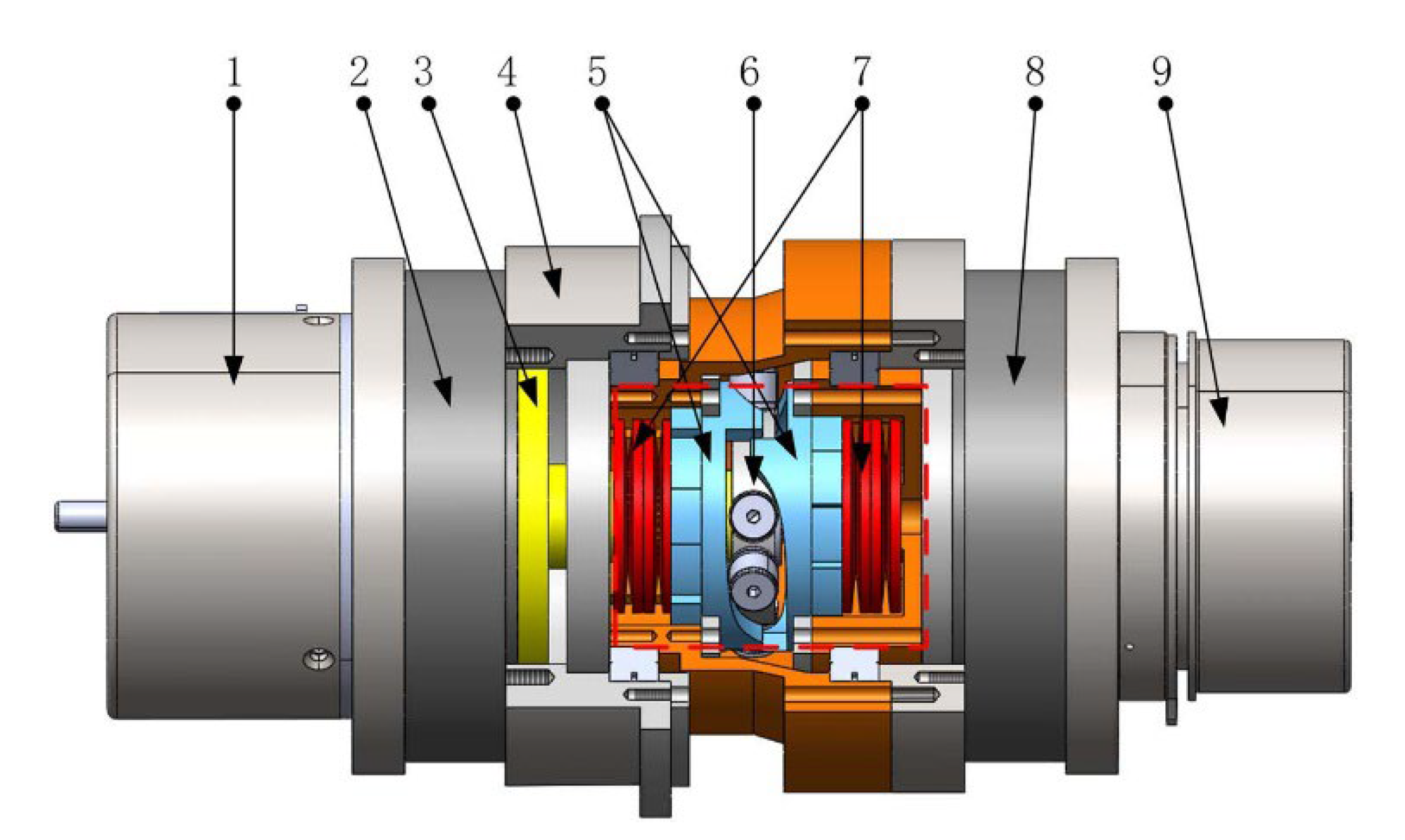
Figure 80.
Steel flexible universal joint [146].
Figure 80.
Steel flexible universal joint [146].
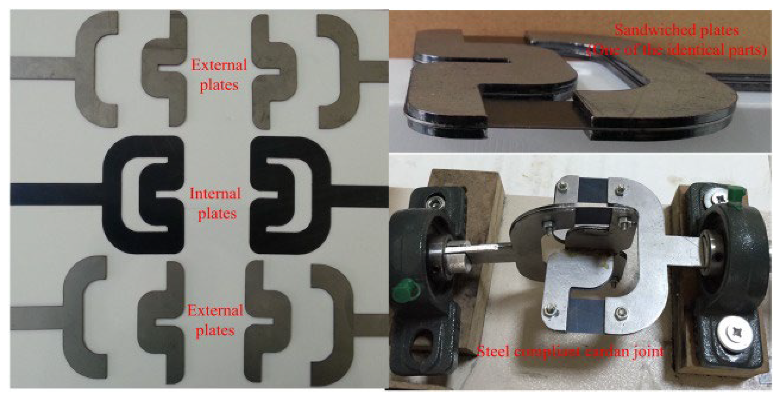
Figure 81.
New anti-buckling universal joint: (a) top view, (b) front view [147].
Figure 81.
New anti-buckling universal joint: (a) top view, (b) front view [147].
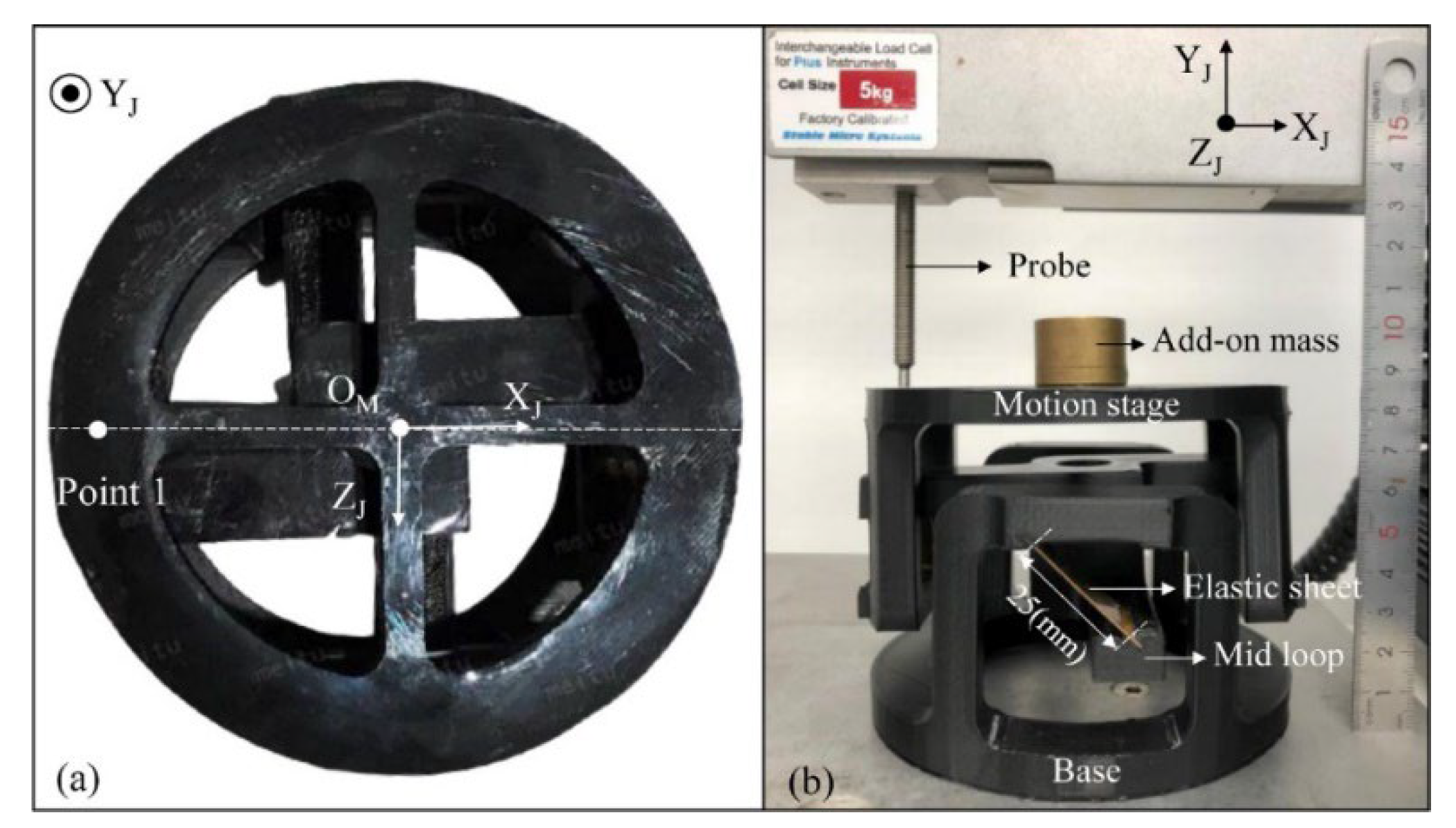
Figure 82.
A new type of fully compliant universal joint [148].
Figure 82.
A new type of fully compliant universal joint [148].
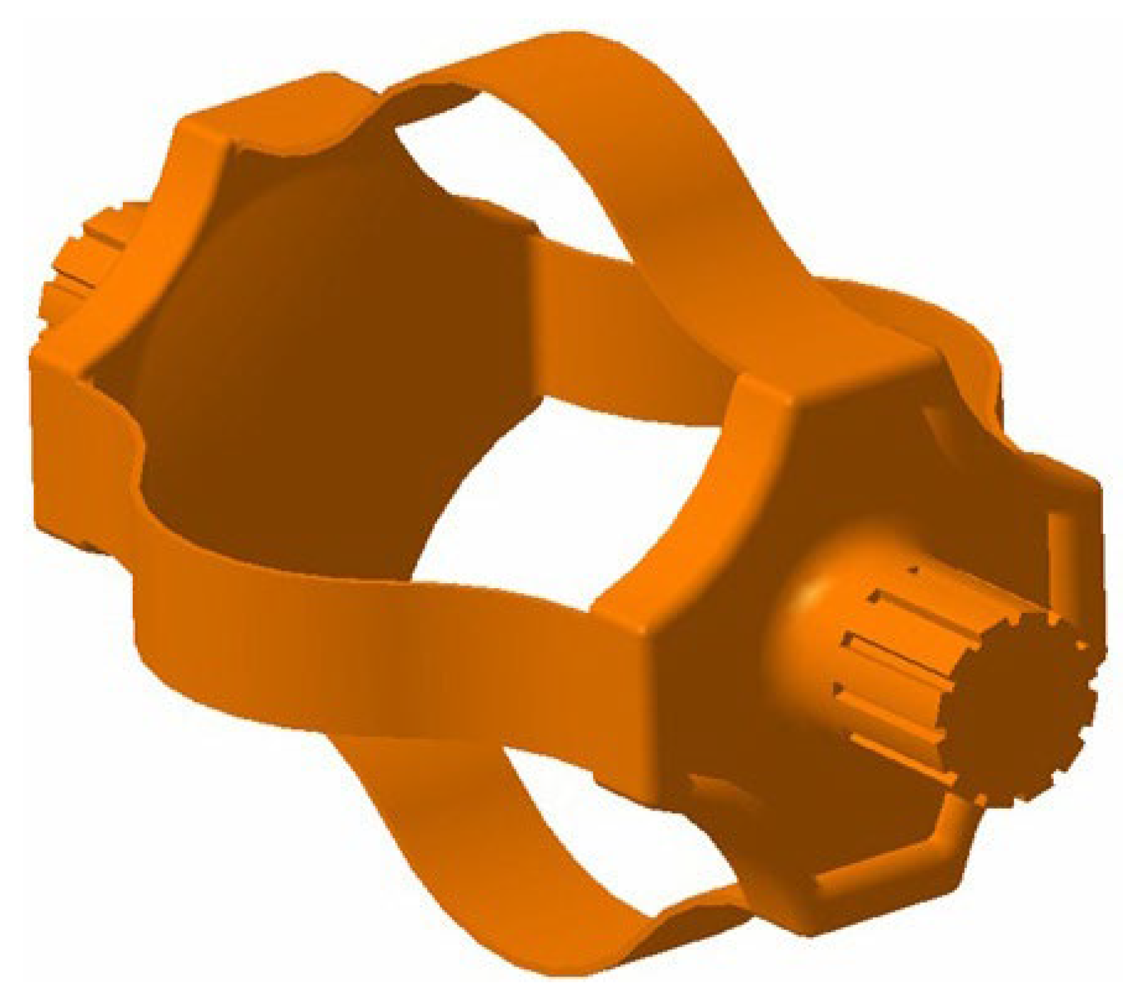
Figure 83.
Schematic diagram of gearless right angle transmission mechanism [149].
Figure 83.
Schematic diagram of gearless right angle transmission mechanism [149].
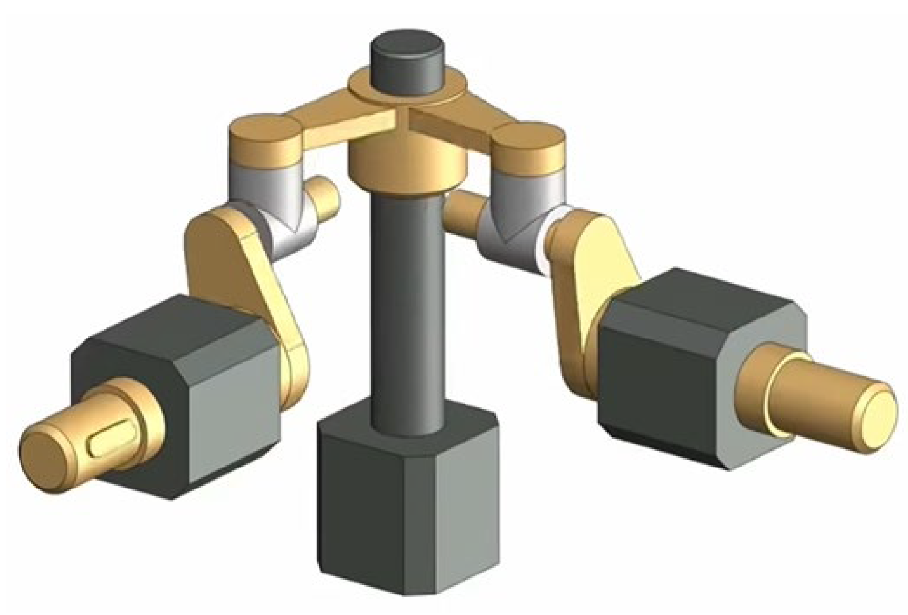
Figure 84.
Schematic diagram of right-angle transmission mechanism [150].
Figure 84.
Schematic diagram of right-angle transmission mechanism [150].
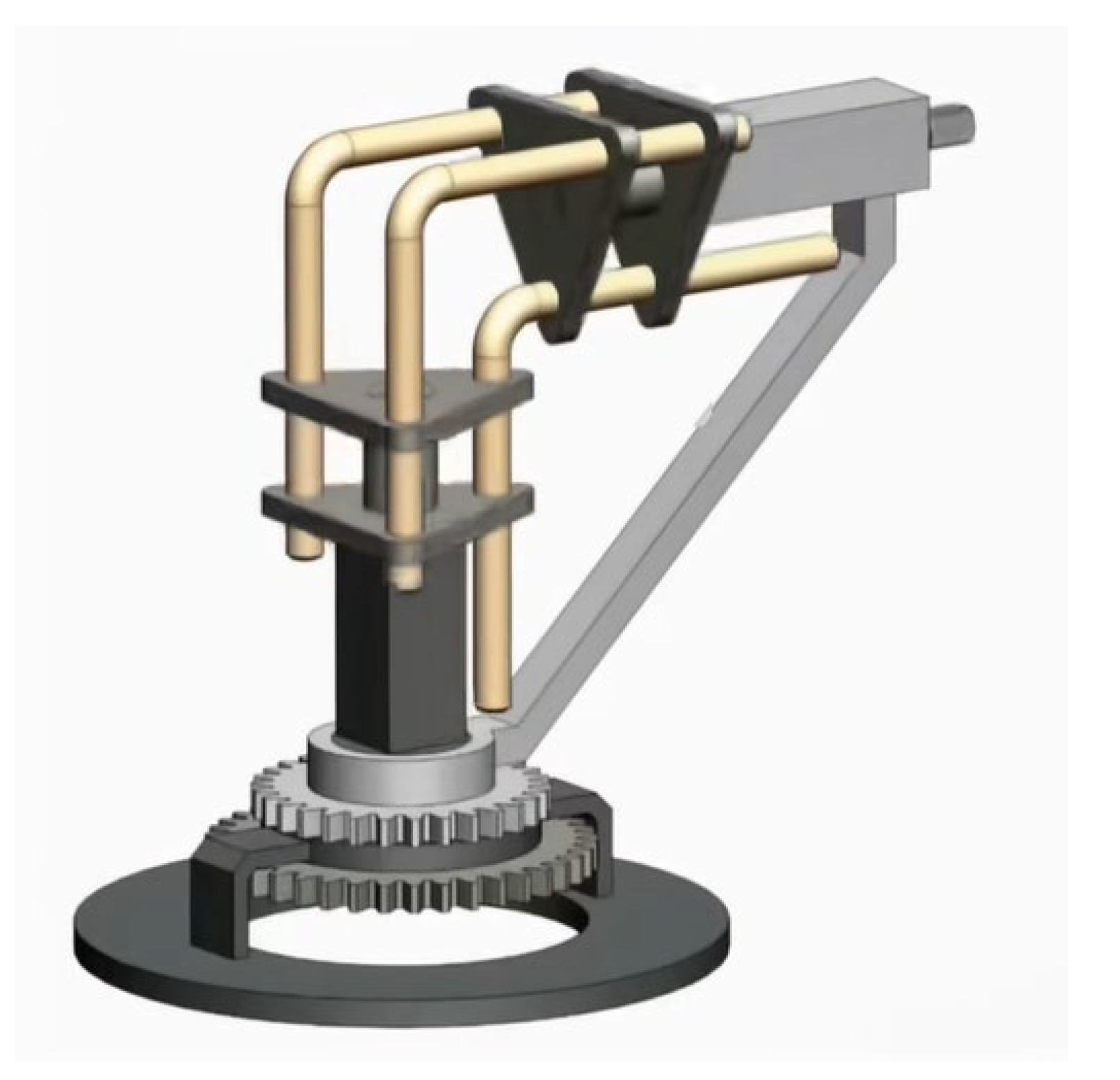
Figure 85.
Spiral gear forward and reverse conversion mechanism [151].
Figure 85.
Spiral gear forward and reverse conversion mechanism [151].
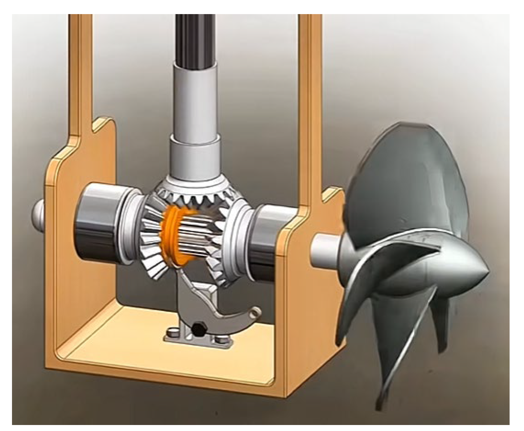
Figure 86.
Ratchet and pawl forward and reverse rotation mechanism [152].
Figure 86.
Ratchet and pawl forward and reverse rotation mechanism [152].
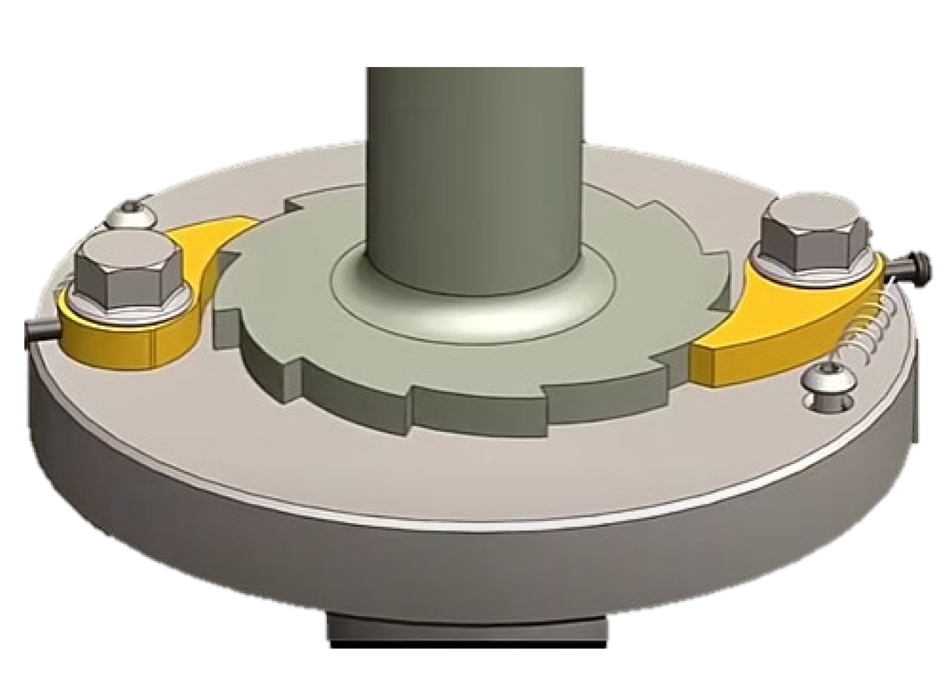
Figure 87.
Classification of motors by purpose [153].
Figure 87.
Classification of motors by purpose [153].
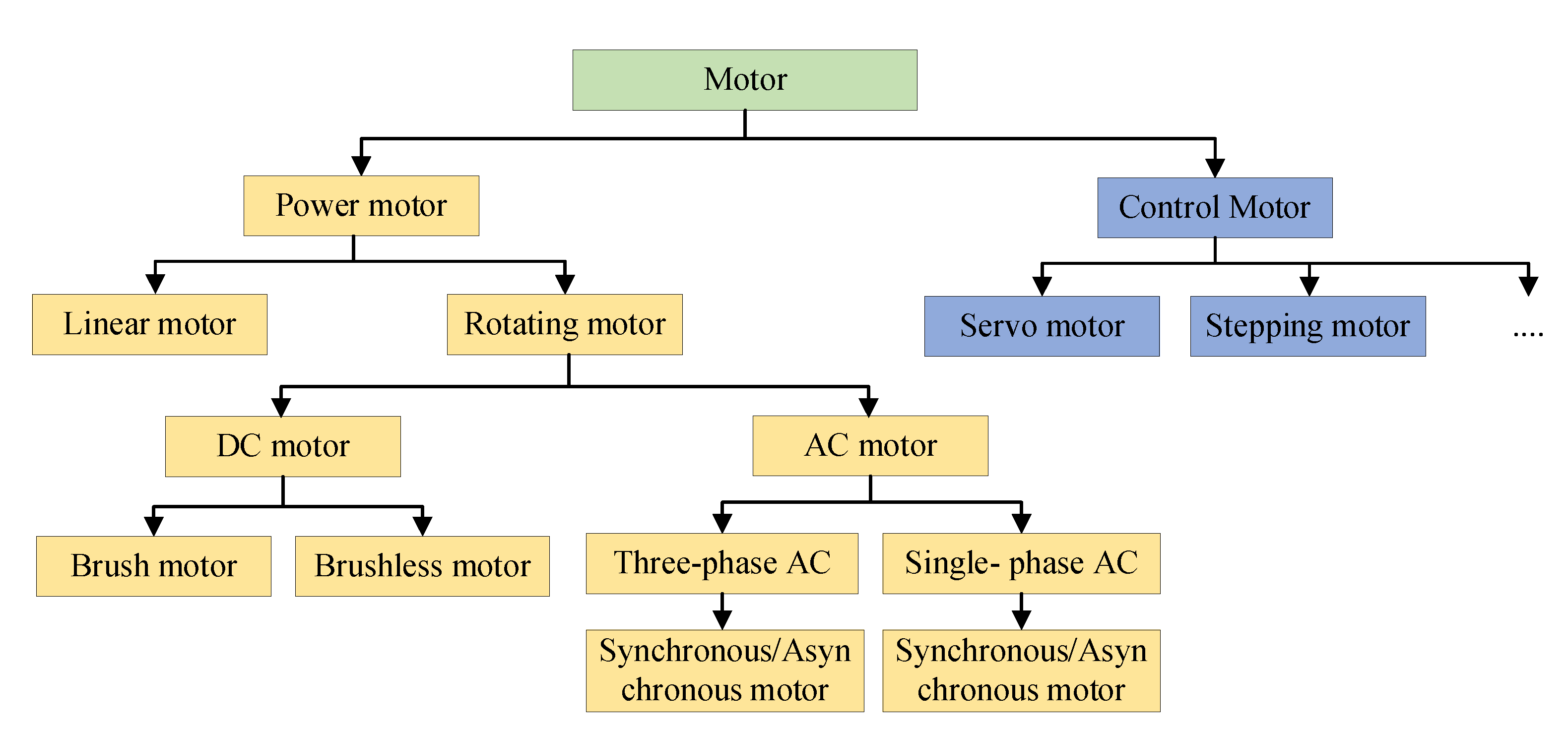
Figure 89.
Composition of spherical motor [175].
Figure 89.
Composition of spherical motor [175].
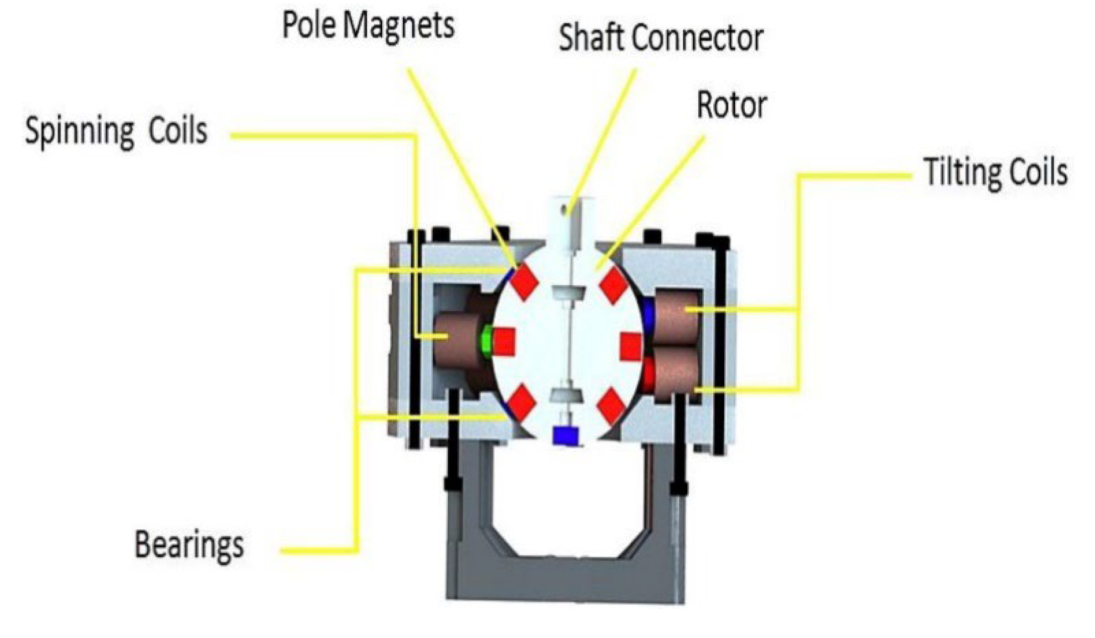
Figure 90.
Component description of prototype motor: (a) stator, (b) outer rotor with magnet, and (c) completed hollow cup motor prototype [179].
Figure 90.
Component description of prototype motor: (a) stator, (b) outer rotor with magnet, and (c) completed hollow cup motor prototype [179].
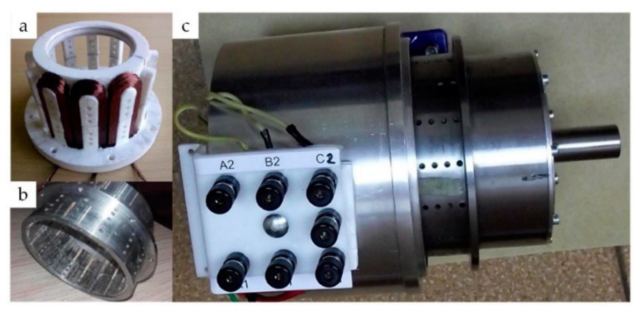
Figure 91.
Proposed structure of a novel rotary ultrasonic motor using only longitudinal vibration mode [182].
Figure 91.
Proposed structure of a novel rotary ultrasonic motor using only longitudinal vibration mode [182].
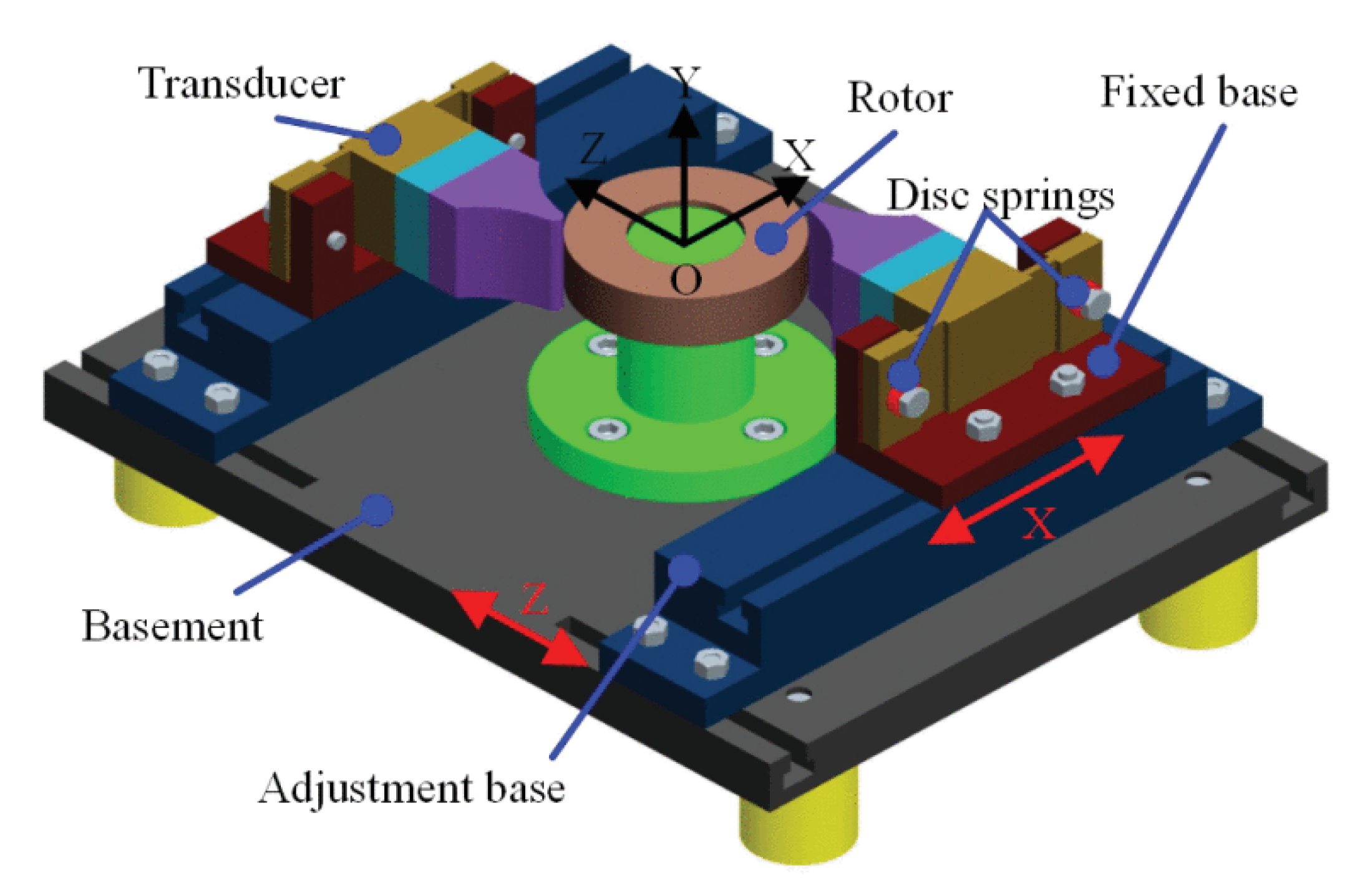
Figure 92.
Structure and main dimensions of non-contact ultrasonic motor [183].
Figure 92.
Structure and main dimensions of non-contact ultrasonic motor [183].

Figure 93.
Three-dimensional model (a) Proposed assembly diagram of the new piezoelectric motor, (B) Structure of the vibrator, (c) Decomposition diagram of the rotor component [184].
Figure 93.
Three-dimensional model (a) Proposed assembly diagram of the new piezoelectric motor, (B) Structure of the vibrator, (c) Decomposition diagram of the rotor component [184].
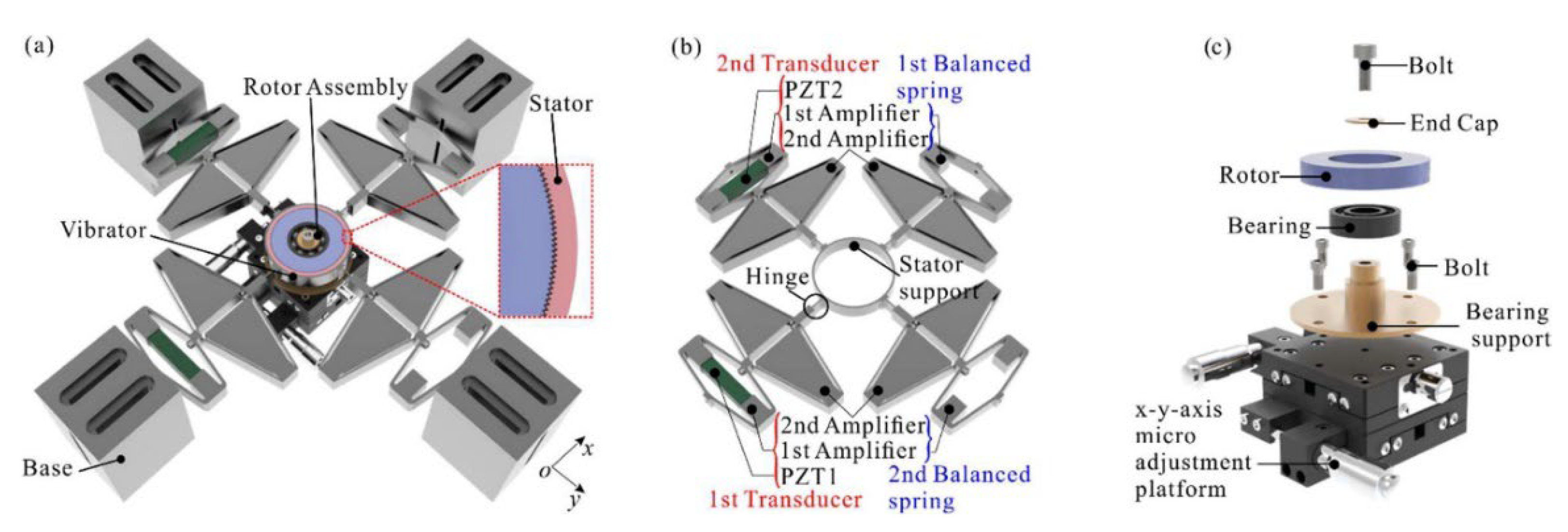
Figure 94.
Proposed Structure of RPA [185].
Figure 94.
Proposed Structure of RPA [185].
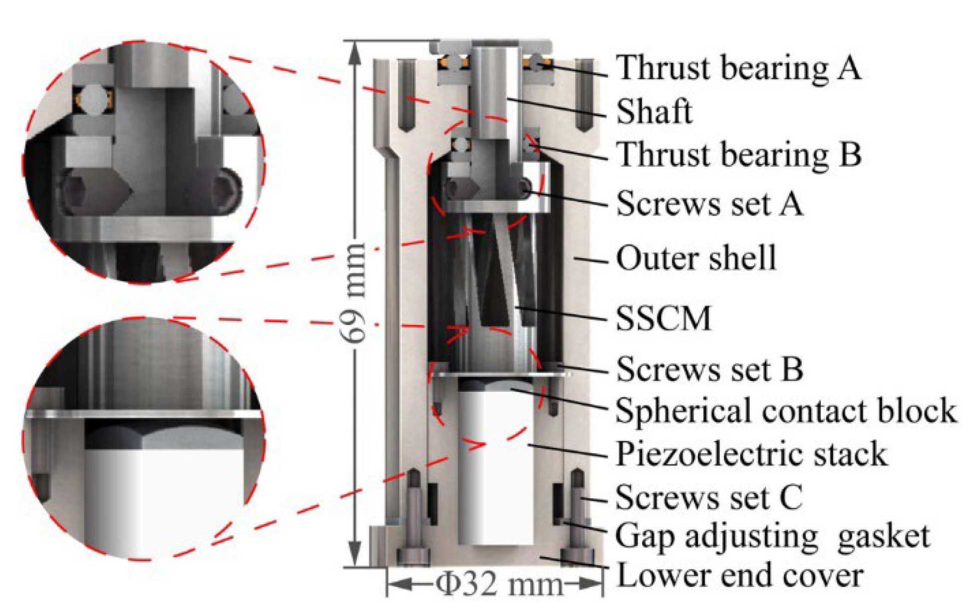
Figure 95.
An EHP structure based on an axial piston [187].
Figure 95.
An EHP structure based on an axial piston [187].
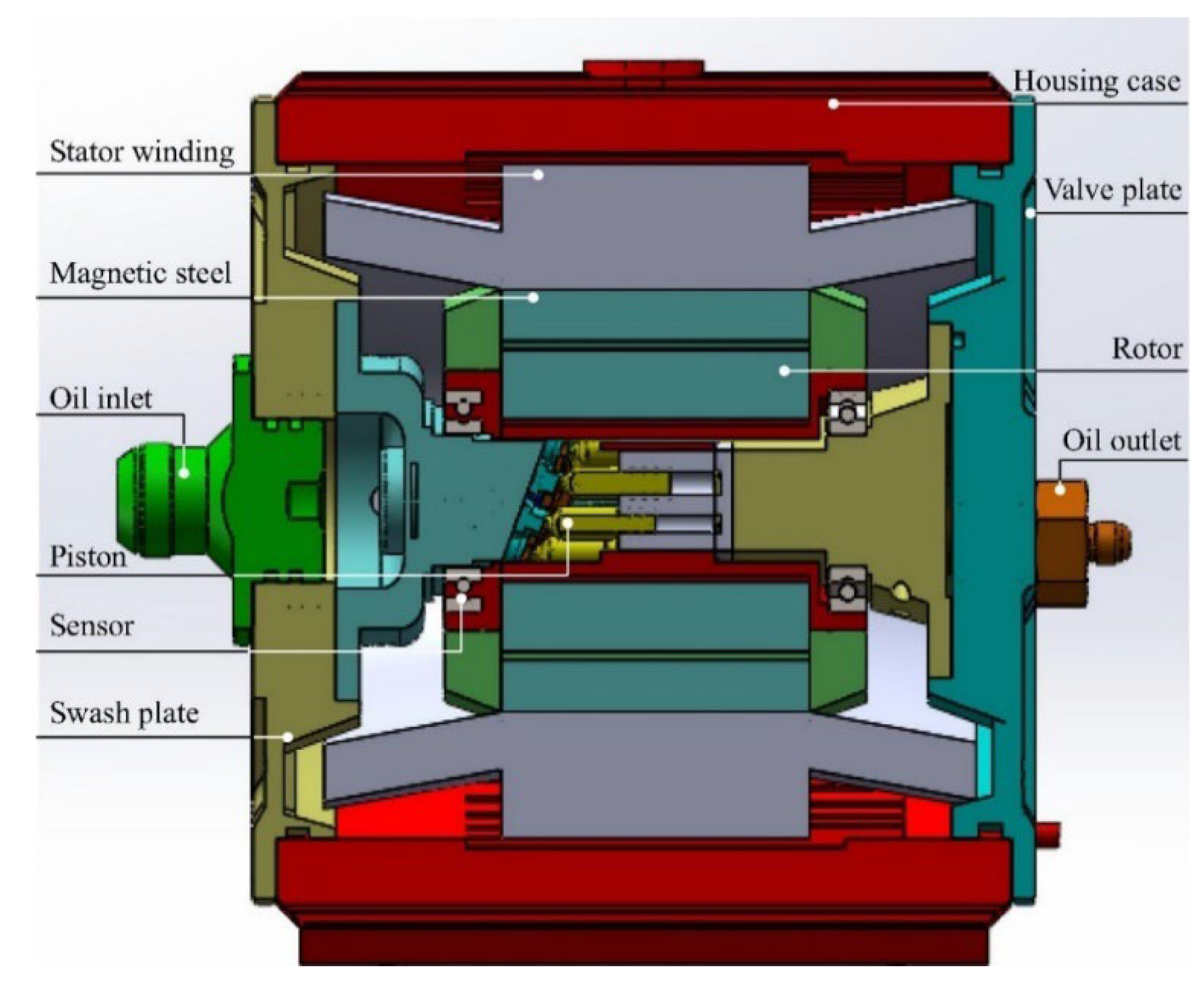
Figure 96.
Schematic diagram of ERHD driving system [188].
Figure 96.
Schematic diagram of ERHD driving system [188].
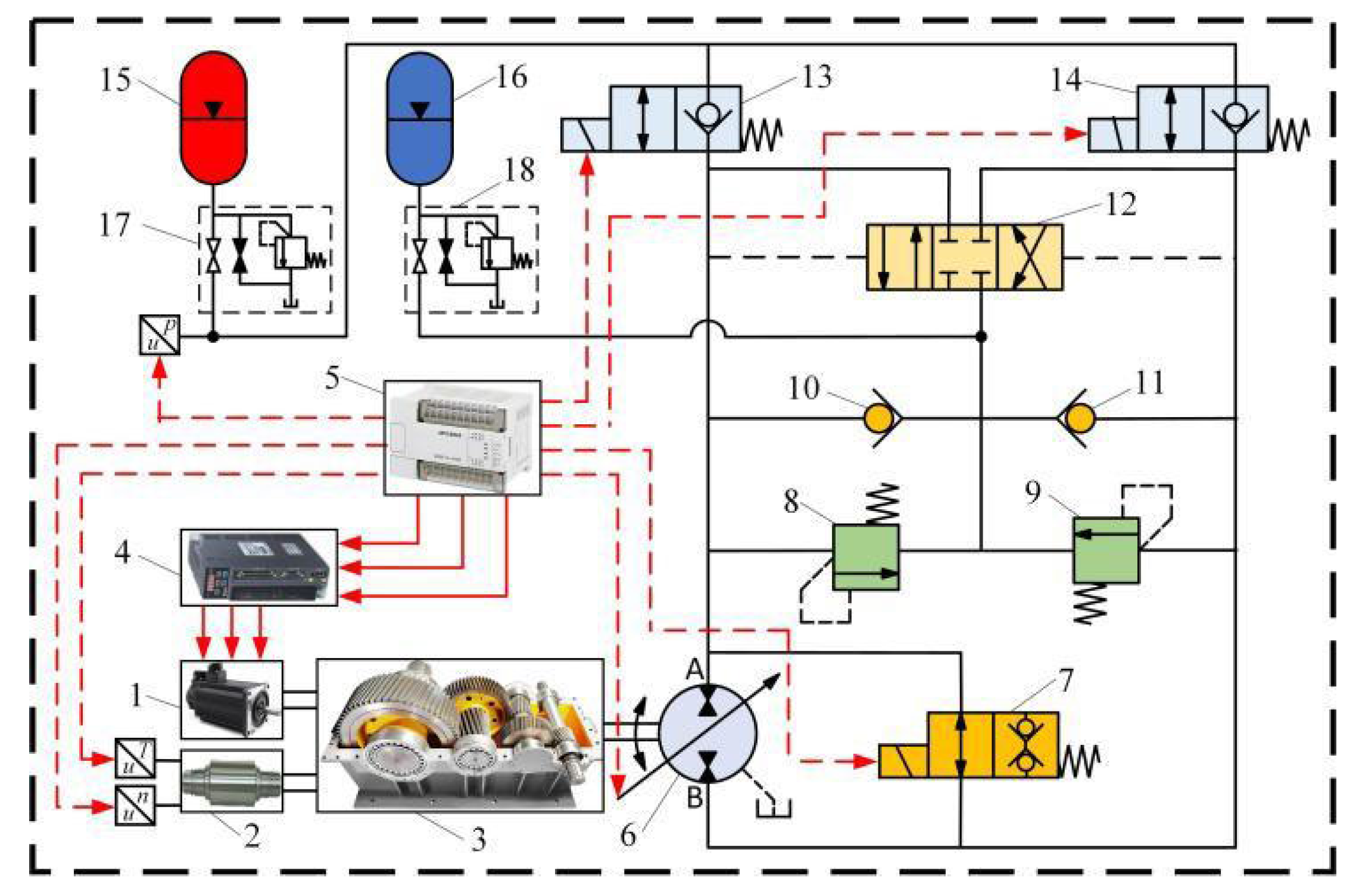
Figure 97.
Multi-mode pneumatic motor based on rigid flexible coupling structure. (a) Assembly drawing. (b) Driving principle. (c) Prototype [193].
Figure 97.
Multi-mode pneumatic motor based on rigid flexible coupling structure. (a) Assembly drawing. (b) Driving principle. (c) Prototype [193].
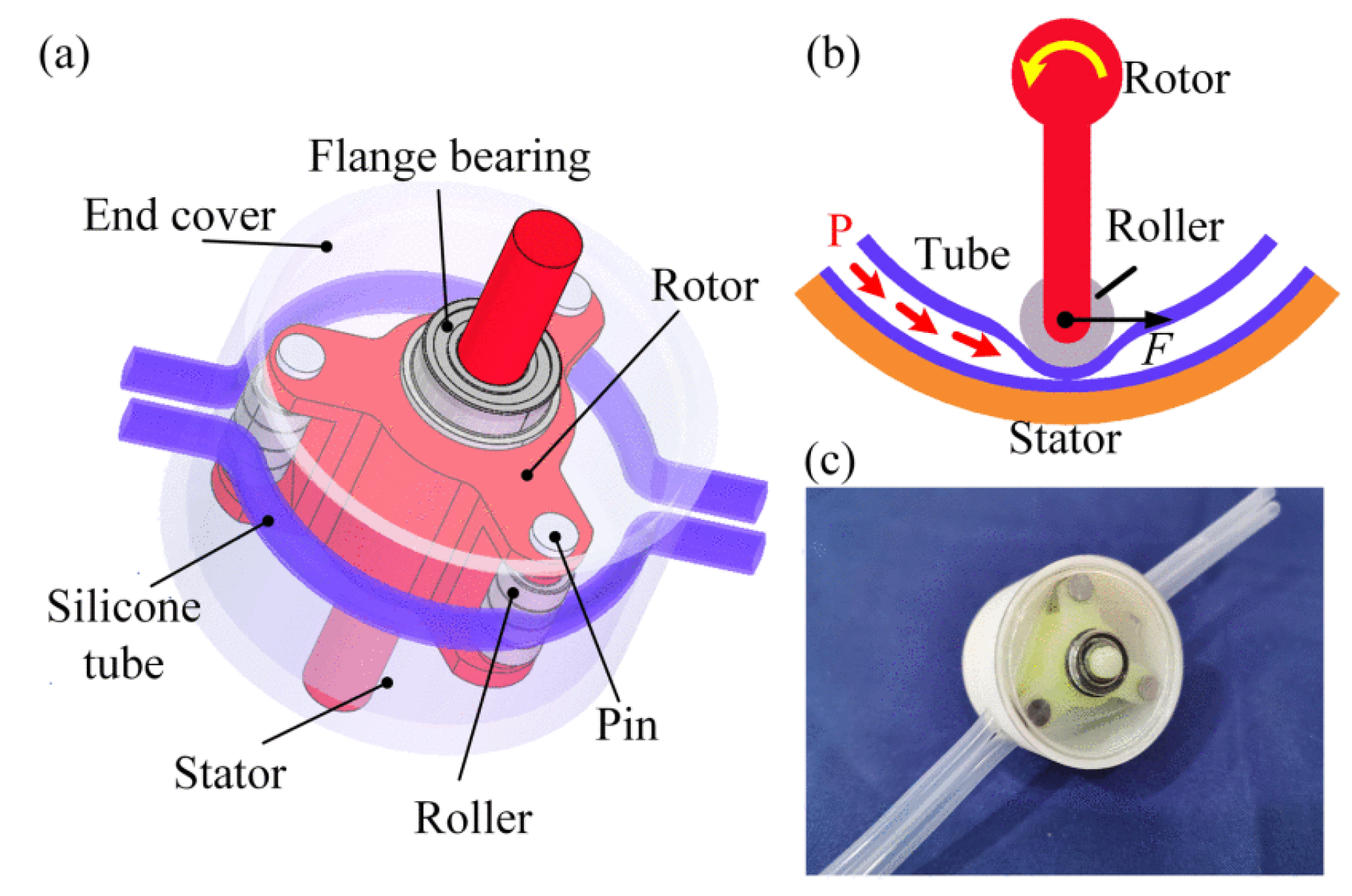
Figure 98.
Realized modular laboratory test stand with five PAMs [194].
Figure 98.
Realized modular laboratory test stand with five PAMs [194].
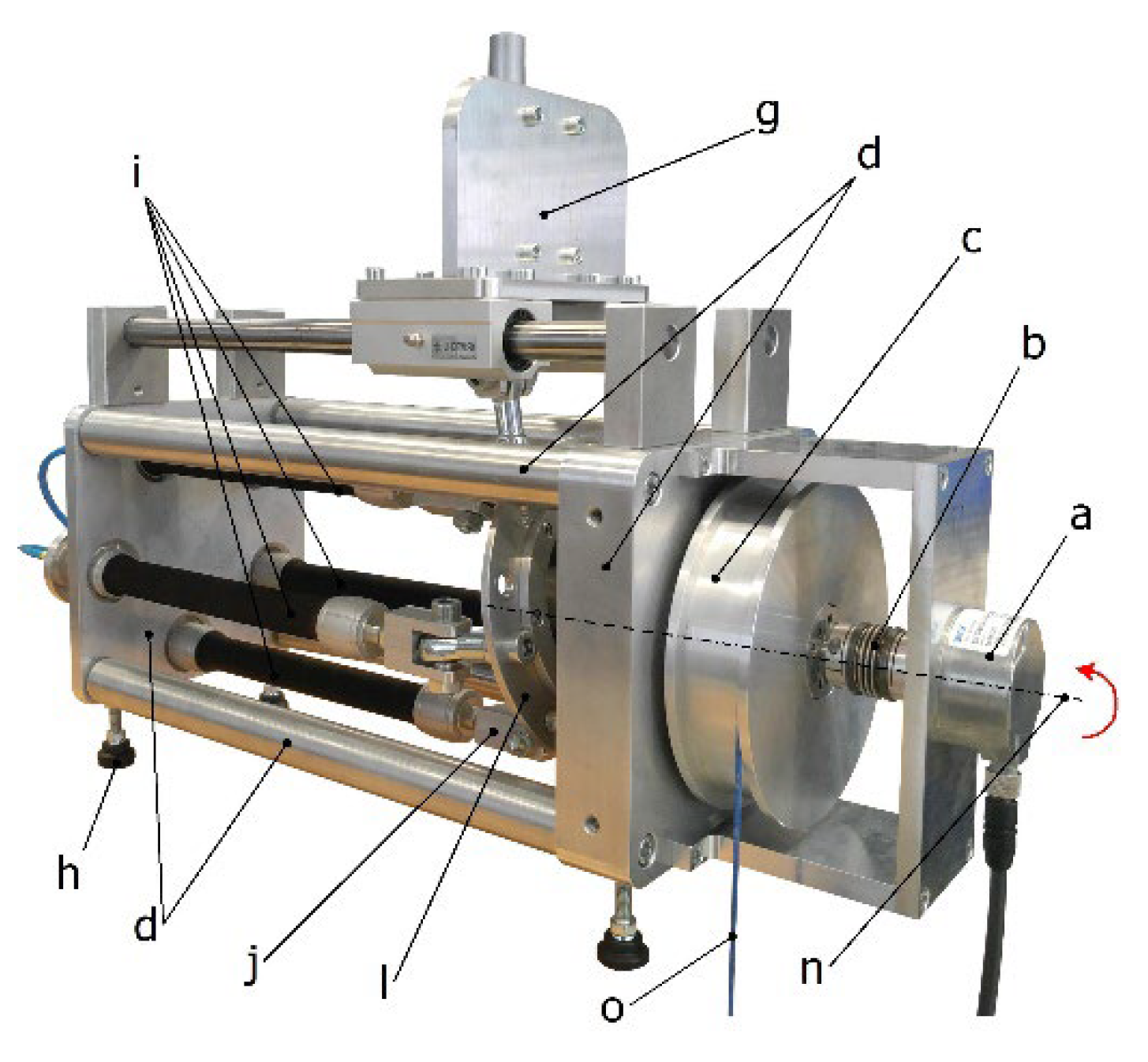
Disclaimer/Publisher’s Note: The statements, opinions and data contained in all publications are solely those of the individual author(s) and contributor(s) and not of MDPI and/or the editor(s). MDPI and/or the editor(s) disclaim responsibility for any injury to people or property resulting from any ideas, methods, instructions or products referred to in the content. |
© 2025 by the authors. Licensee MDPI, Basel, Switzerland. This article is an open access article distributed under the terms and conditions of the Creative Commons Attribution (CC BY) license (http://creativecommons.org/licenses/by/4.0/).
Copyright: This open access article is published under a Creative Commons CC BY 4.0 license, which permit the free download, distribution, and reuse, provided that the author and preprint are cited in any reuse.


