
Submitted:
15 March 2025
Posted:
18 March 2025
You are already at the latest version
Abstract
Digitalisation and Industry 4.0 are finding their way into more and more socially and industrially relevant areas. Even sectors characterised by craftsmanship and small and medium-sized enterprises, such as the foundry industry, which is struggling with these topics for various reasons, can no longer escape this development. What is needed, however, are solutions that do justice to the individual conditions of the various companies and allow for easy implementation. Only this way small and medium-sized enterprises, which often have a low level of automation, will have access to the data-based insights that come with digitalisation, which above all contribute to a better understanding of their own processes and, based on this, to higher efficiency and competitiveness. This article describes the development and application of a holistic open-source soft-ware-based solution for the digital real-time acquisition, storage and visualisation of relevant process data along the process chain for the manual production of aluminium castings (but also higher-melting alloys) on a scalable prototype level. The casting ladle was developed according to the Industry 5.0 strategy of the European Union and includes, on the one hand, the use of sensor units for flexible process-related data acquisition and, on the other hand, the use of a new type of connected employee-centred casting ladle for real-time acquisition of the relevant process parameters during manual casting. The evaluation of the casting tests carried out within the framework of this setup not only proves an increase in the reproducibility of the properties of manually produced castings through the real-time visibility of the data. In addition, the subsequent data evaluation and transparency allows detailed insights into the production process, the prevailing casting parameters and their correlation with the achieved casting properties. The presented solution thus has the potential for the development of a deeper understanding of the casting-specific correlations between production parameters and achievable casting properties. This in turn enables the development and establishment of more tailored and efficient processes as well as more profound insights in the field of (academic) research and development as well as in the industrial environment.
Keywords:
Industry 4.0
; industry 5.0
; foundry
; process monitoring
; mqtt
; data acquisition
; process transparency
1. Introduction
The foundry industry is a key supplier for a large number of socially relevant sectors such as wind turbine production, medical and electrical engineering, infrastructure and mechanical engineering, shipbuilding, rail technology, aerospace and not forgetting automotive manufacturing [1]. This makes the foundry industry an important sector worldwide for the development and implementation of innovative product solutions and the achievement of politically set goals in the areas of mobility and renewable energies, among others. In many places, it is the foundry industry that makes the widespread use of new technologies suitable for large-scale production possible in the first place, such as the production of vehicles with new types of engine concepts in quantities that, despite the rapid developments in the field of additive manufacturing, can only be achieved through the use of casting technology solutions and will continue to be so in the future [2].
At the same time, the foundry industry is characterised by a millenniaold tradition that continues to this day. The process of casting production has hardly changed over decades and centuries [3]. With the exception of a few highly modern automated foundries, such as those frequently found in automotive production at the Original Equipment Manufacturers (OEM) and their high-volume suppliers, the foundry industry is a medium-sized sector with a still pronounced proportion of manually performed work steps, in which only a few companies have so far entered the increasingly relevant technology fields of digitalisation and Industry 4.0. In Germany alone, one of the most important industrial locations in the world, 90% of all foundries are small and medium-sized enterprises (SME), which employ around 50% of the people working in the German foundry industry [4]. A large proportion of these craft-based companies are struggling to enter the important technology fields of digitalisation and Industry 4.0, for the following reasons, among others:
Against the background of these causes, technological solutions are necessary that meet the individual conditions of these foundries, are easy to use, include state-of-the-art technology and whose added value is immediately recognisable for both the management and the employees. In the following, a technological solution that can be used flexibly along the process chain for aluminium casting production is presented on a prototype scale, which, using the example of temperature recording, the most important parameter for casting production, enables real-time recording, storage and visualisation of the measurement data for manual casting production. The solutions presented rely on state-of-the-art communication technology, are scalable in terms of both quantity and material, and are designed to support humans as the central element of manual casting production.
2. Theory
2.1. Process Chain of Aluminium Casting Production
The process chain for aluminium casting production usually comprises the sequential process steps shown in Figure 1 (sand core production not considered).
After melting the stored aluminium ingots in gas or electrically heated melting furnaces (1), the finished melt is transferred to transport ladles (2). With the help of these, the melt is transported to holding furnaces at the respective casting stations using overhead cranes or fork-lift trucks (3). As an alternative to the above-mentioned process, solutions are also being developed that still provide for melting and holding at different locations, but in the same container, thus avoiding transfer-pouring processes that impair the melt quality [11]. In the holding furnace, the melt is kept at the target temperature and treated (3). Depending on the alloy, the treatment includes grain refinement and refining, but in any case, cleaning and degassing of the melt [12,13]. After these measures have been completed, the alloy composition is checked, usually by means of a spark spectrometer, as is the melt quality, usually with the aid of reduced pressure test, also known as Straube-Pfeiffer test [14]. In case of deviations, rectification is carried out, otherwise the casting process is initiated. Parallel to this, the mould is prepared (4). In the field of aluminium casting production, this usually involves a metallic mould made of tool steel [15]. The mould is coated in advance, mainly to protect the mould and to enable easy removal of the castings after solidification and heated to operating temperature. Depending on the casting, mould temperatures between 200 and 400 °C are provided here [16,17]. Once the mould has been prepared accordingly and the melt in the holding furnace has been released, the casting process takes place (5). Manual casting production involves the use of metal ladles made of steel [18]. The employee coats the area of the ladle that receives the melt to avoid adhesions and to ensure good flow behaviour of the melt out of the ladle. To extract the melt, the employee immerses the ladle in the holding furnace and remains there with it for some time so that the casting tool reaches the temperature of the melt, thus its temperature does not drop too quickly when the melt is removed from the holding furnace. After extracting the melt with the ladle, the foundryman positions the spout of the ladle over the sprue of the mould and initiates the pouring and mould filling process by rotating the ladle around its longitudinal axis. After complete solidification, the casting is removed from the mould and stored for cooling to room temperature. Depending on the mechanical properties required, the finished castings are subjected to a usually three-stage heat treatment (6) consisting of solution annealing, quenching and (hot) ageing [13,19]. The quality of the heat treatment, i.e. the achievement of possible mechanical characteristics, depends on the qualitative basis of the casting created during the casting and solidification process [20]. Following the heat treatment process, the castings are passed on to the next production steps and processes such as cutting and grinding [21].
2.2. Critical Review of the Manual Casting Process
The process of actual casting production described in Section 2.1 (5) requires critical consideration. Assuming an adequately designed casting tool, the quality of the casting is primarily depending on the mould and melt temperature. The temperature regime under which the casting solidifies influences the formation of the average grain diameter and thus the cast part structure [22,23,24,25,26,27]. This can be quantified in downstream inspection processes with the help of microscopically analysed microsections based on the measurement of the grain size, allowing direct conclusions to be drawn about the casting quality and, by means of the Hall-Petch equation, often also about the resulting mechanical properties [28,29]. The casting quality achieved during casting thus creates the basis for all downstream manufacturing and process steps and the quality of the final component and its assembly. The control of the mould and melt temperature during casting thus plays a dominant role, as they have a decisive influence on the casting quality. Secondary, but also relevant, is the execution of the mould filling through the handling of the ladle by the employee [30]. Here, the experienced handling of the casting tool must ensure that the mould is filled as laminarly as possible, i.e. with as little turbulence as possible, in order to avoid air inclusions and thus the occurrence of porosity and oxides in the casting [12,13]. In the context of manual casting production, the expertise of the employee thus plays a key role, as he is ultimately responsible for ensuring compliance with the target parameters and the execution of the casting process.
However, the employee is only as good as the information he is provided with. In common practice, during mould filling, i.e., the central value-adding process step, the foundryman no longer has any information about the thermal framework conditions. As a rule, neither about the mould temperature nor about that of the melt. Even assuming that the mould temperature is largely constant, which is usually not the case because the area of the cavity is often preheated with an open gas flame and the mould heats up in the course of the successive castings [31], the employee does not know the exact state of the melt in the ladle after extracting the melt from the holding furnace. The longer the time interval between the removal of the melt from the holding furnace and the casting process, the more incalculable this state becomes. Moreover, even in retrospect, no insights are possible that would allow conclusions to be drawn about the cause of any defects that occur.
2.3. Potentials of Digitalisation and Industry 4.0 for Manual Casting Production
Against the background of the constantly advancing developments in the fields of digitalisation and Industry 4.0 and their potential for process transparency, the conditions described in Section 2.2 hardly meet the requirements of modern production. Both developments offer the same opportunities for foundries as for all other areas of their application: The visibility of measured/relevant process data. Referring to >>The six stages of the Industry 4.0 development path<<, digitalisation includes (1) computerisation and (2) connectivity of processes. Building on this, Industry 4.0 includes (3) visibility and (4) transparency of data, which enables (5) predictability and (6) adaptability of sensory measurement data [32].
Contrary to the often widespread assumption of the inevitable interlocking of Industry 4.0 with automated processes or, conversely, an incompatibility of Industry 4.0 with manually executed process steps [33,34,35], the latter two aspects are indeed compatible. Against the background of the contexts and conditions explained in Section 2.2, the realisation of a solution that enables the (real-time) visibility and, based on this, the transparency of the central manually determined casting technological process data - specifically the mould and casting temperature as well as the mould filling - already falls within the scope of Industry 4.0.
The real-time availability and provision of this data shortly before and during casting would allow the foundryman to take this data into account in his casting process execution and to achieve a higher degree of reproducibility. This paper follows this approach and presents technological solutions that enable foundries with manual casting production to enter the technology fields of digitalisation and Industry 4.0. Specifically, this includes the development of flexibly applicable sensor units and the use of a newly developed, sensor-based and connected Casting Ladle 4.0, which, as an employee-centred solution in the sense of the Industry 5.0 initiative of the European Union [36,37,38], allows the real-time recording of the relevant casting parameters on the part of the foundryman, specifically the melt temperature and the casting curve [39].
Together, the developed solutions enable comprehensive, locally and demand-oriented real-time monitoring (computerisation and connectivity) of the relevant process parameters with corresponding real-time visualisation (visibility) in manual casting production as well as a well-founded analysis of the process-related interrelationships in manual casting production based on the process data collected in this way (transparency) with the potentials of predictability and adaptability.
3. Material and Methods
In the following, the components used for the implementation of the project, their configuration and their interconnection are described.
3.1. Infrastructure
3.1.1. Hardware
The central computing unit is a Lenovo ThinkCentre M90q (Lenovo) with Ubuntu Linux distribution, which is integrated into an inhouse network created for this purpose and provided by a FRITZ!box 4040. An industrial full HD monitor and RealWear Navigator 500 industrial data glasses are used for visualising the measurement data.
3.1.2. Software
The software infrastructure for data acquisition is shown in Figure 2. The Lenovo computer unit is used to receive and store the incoming measurement data and simultaneously enables access to the data and its real-time visualisation. The communication between the Lenovo computer unit and the measuring units described in Section 3.2 and Section 3.3 is carried out using the Mosquitto MQTT communication protocol from the Eclipse Foundation [40]. The measuring units are the senders of the measurement data, i.e. MQTT clients in the context of the MQTT protocol, which transmit the data to the Lenovo computer acting as a broker. The incoming measurement data is stored with the help of the time series database InfluxDB [41]. The programming and configuration of the measurement data streams from the data input to the data bank is achieved by using the visual programming tool Node-RED [42]. For the real-time visualisation of the measurement data from the InfluxDB database, the visualisation programme Grafana is used [43], which enables a needs-oriented visualisation of the measurement data by creating dashboards. A more detailed explanation of the programmes used, and their interaction can be found in [10].
3.2. Sensor Units
3.2.1. Hardware
The central element of the sensor units, schematically illustrated in Figure 3, is an ESP32 microcontroller with WLAN function, which can thus be integrated into the network generated by the FRITZ!box and transmit the sensor data using the MQTT communication protocol. The microcontroller can be powered either wirelessly using a LiPo battery (or similar) or via a USB cable. An MCP9600 Thermocouple Amplifier with OMEGA miniature connector interface (PCC connector) for plug&play connection of thermocouples is connected to the ESP32 for temperature detection via I2C [44].
3.2.2. Software
The ESP32 microcontroller was programmed with Arduino IDE 2.0 and includes the definition of the thermocouple types used, in this case type K, the integration into the network created and its integration into the MQTT communication protocol for sending the data. In this case, data reception by the sensor units is not intended and therefore not programmed, but it is possible via the so-called MQTT callback function. Arduino IDE 2.0 also allows wireless programming within the network via over-the-air updates.
3.3. Casting ladle 4.0
3.3.1. Hardware
As close as possible to the design of a conventional ladle, the Casting Ladle 4.0, illustrated in Figure 4, consists of a two-part, modular handle, at one end of which is the cup for holding the melt and at the other end of which is the handle. In the upper part of the handle, the ladle can be disassembled and allows the lower part of the ladle, which comprises the cup and is subject to wear, to be replaced as required. The upper part of the ladle contains the electronic and sensory components necessary for process monitoring. At the interface between the modules there is also an interface with PCC connector for easy connection and exchange of thermocouples. A BNO055 Absolute Orientation Sensor from Bosch is used to record the ladle movements and thus also the casting curve. Both sensors are connected via I2C to an ESP32, which is powered by a LiPo battery. The battery is charged inductively using a wireless charging coil. A detailed description of the aspects considered in the development of the Casting Ladle 4.0 can be found at [39].
3.3.2. Software
The programming of the Casting Ladle 4.0 was carried out in accordance with the same aspects as in the case of the sensor units and thus corresponds to the descriptions in Section 3.2.2 The components used for digital process recording are shown again in Figure 5.
4. Experimental Setup and Execution
The experimental setup is shown schematically in Figure 7. In addition to the melting and holding furnace of type K 4/13 from Nabertherm, which can be tilted for ladle filling, this comprises the mould prepared at the casting station including the heating device and the monitor for visualising the measurement data. Sensor units with connected type K thermocouples for temperature measurement and monitoring were installed on the furnace with the thermocouple immersed in the melt and in the mould wall for determining and monitoring the meld and mould temperature, respectively. An aluminium alloy of the type AlSi7Mg (A356) was processed, which was melted and kept at a temperature of 740∘C. The mould temperature was programmed to 300∘C. A Casting Ladle 4.0 with a ceramic fibre shell was used for casting. The target and for visualisation defined pouring temperature was 720∘C. The measuring accuracy of the measuring equipment used here was checked and validated in advance using a Fluke 714B thermocouple calibrator.
The visualisation of the measurement data was carried out as described using the Grafana software on the one hand via the industrial monitor set up at the casting station and on the other hand via the industrial data goggles the display of which was located on the inside of the caster’s helmet visor. To carry out the casting process, the thermocouple was removed from the furnace and the ladle was filled by tilting the furnace. After completion of the ladle filling, the furnace was tilted back to its initial position and the thermocouple was inserted again. The caster then positioned himself with the ladle at the casting station and brought the ladle into position over the sprue of the mould. In this position, he waited until the melt temperature measured in the ladle and visualised on the monitor, or the data goggles, reached the previously defined pouring temperature before starting to fill the mould. As soon as this was the case, the display of the melt temperature turned green and thus released the casting process for the employee. After completion of the casting process, any excess melt in the casting ladle was returned to the melting furnace and the furnace was charged with new aluminium ingots for the next casting. At the same time, the casting solidified, after which the mould was opened, the casting removed and then the mould closed again in preparation for the next casting. A picture of the experimental procedure can be found in Figure 7.
5. Results and Discussion
While the possibilities for increasing the reproducibility of manually produced castings using the Casting Ladle 4.0 were already investigated in [39], the focus of the here presented results was the analysis of the process data collected during production and the potential of its data-driven value as well as the derivation of process-related optimisation potential. The data collected during the casting processes was accessed with the help of the Grafana software and exported for the evaluations described in Section 5.
5.1. Detailed Casting Process Analysis
Figure 8 shows the evaluation of an exemplary casting trial with which the casting process described in Section 4 can be reproduced based on the curves shown. Point 1 in Figure 8 marks the removal of the thermocouple from the furnace in preparation for the tilting filling of the ladle. The rise of the temperature curve of the ladle starting with point 2 shows the beginning of the filling on the side of the ladle by the (first) contact of the thermocouple with the melt until the actual melt temperature is reached at point 3. The end of the mould filling is marked at point 4 at the latest with the repositioning of the thermocouple in the furnace. The difference between the melt temperature in the furnace at point 1 and the one measured in the ladle at point 3 allows conclusions to be drawn at this point about the loss of temperature or energy caused by the melt cooling betweens its extraction and the casting process. During this time, the caster positions the ladle by tilting it slightly, point 5, so that mould filling can begin as punctually as possible when the target temperature is reached. The melt temperature in the ladle drops to the defined target temperature of 720∘C, whereupon, marked by point 6, the pouring process is initiated, recognisable by the course of the angle of rotation in the z-axis and the melt pool movement caused by the tilting movement of the ladle as well as the associated temperature fluctuation in the melt pool. Point 7 marks the end of mould filling by changing the rotation direction of the ladle. As a result of the mould filling and the resulting contact of the >700∘C hot melt with the walls of the mould preheated to 300∘C, the mould gains additional heat and the temperature of the mould rises, indicated by point 8. Following the casting process, the excess melt still in the ladle is tipped back into the furnace, indicated in point 9 by the pronounced rotational movement around the z-axis of the ladle, which should enable the ladle to be completely emptied.
Figure 9 a) and b) provide a more detailed insight into the actual casting process. The curve shown in Figure 9 a) shows the rotational movement of the ladle around its longitudinal axis and thus the progress of the casting curve. Point 5 illustrates the prepositioning of the ladle in the waiting position until the target temperature is reached in detail, marked by point 6 in Figure 9 b). The end of the mould filling is marked by the change in direction of the rotary movement in point 7, as already mentioned above. The duration of the mould filling is the period between points 6 and 7.
In addition to the analysis of individual casting processes, it is logically also possible to compare them with each other. This can be seen in Figure 10 using the example of different casting curves, which show a certain spread. The two-dimensional deviations can be assigned to two primary causes according to the x- and y-axis. Temporal deviations along the x-axis are primarily caused by the behaviour of the caster and its reaction behaviour when reaching the target melt temperature. The cause of the deviation along the y-axis is presumably different filling levels or melt volumes within the ladle. This in turn causes varying tilt angles, since, for example, with a more filled ladle, the tilt angle for initiating the casting process is smaller than with a less filled ladle, which must perform a significantly greater rotation around the longitudinal axis to initiate the casting process, as shown as an example in Figure 11.
This relationship is illustrated by a concrete example in Figure 12, in which the temperature curve and the pouring curve of two different casting processes are compared. Process 1 has a lower filling level of the ladle compared to process two. A higher angle of rotation is therefore necessary to initiate the casting process. In addition, the lower melt volume results in a faster cooling of the melt since the surface-to-volume ratio is lower. Thus, assuming a constant mould cavity or casting volume (casting cavity + gating and feeder system), direct conclusions can be drawn about the initial melt volume in the ladle with the help of the collected data and, for example, the importance of a constant filling level across all castings can be worked out.
5.2. Macroscopic Process Analysis
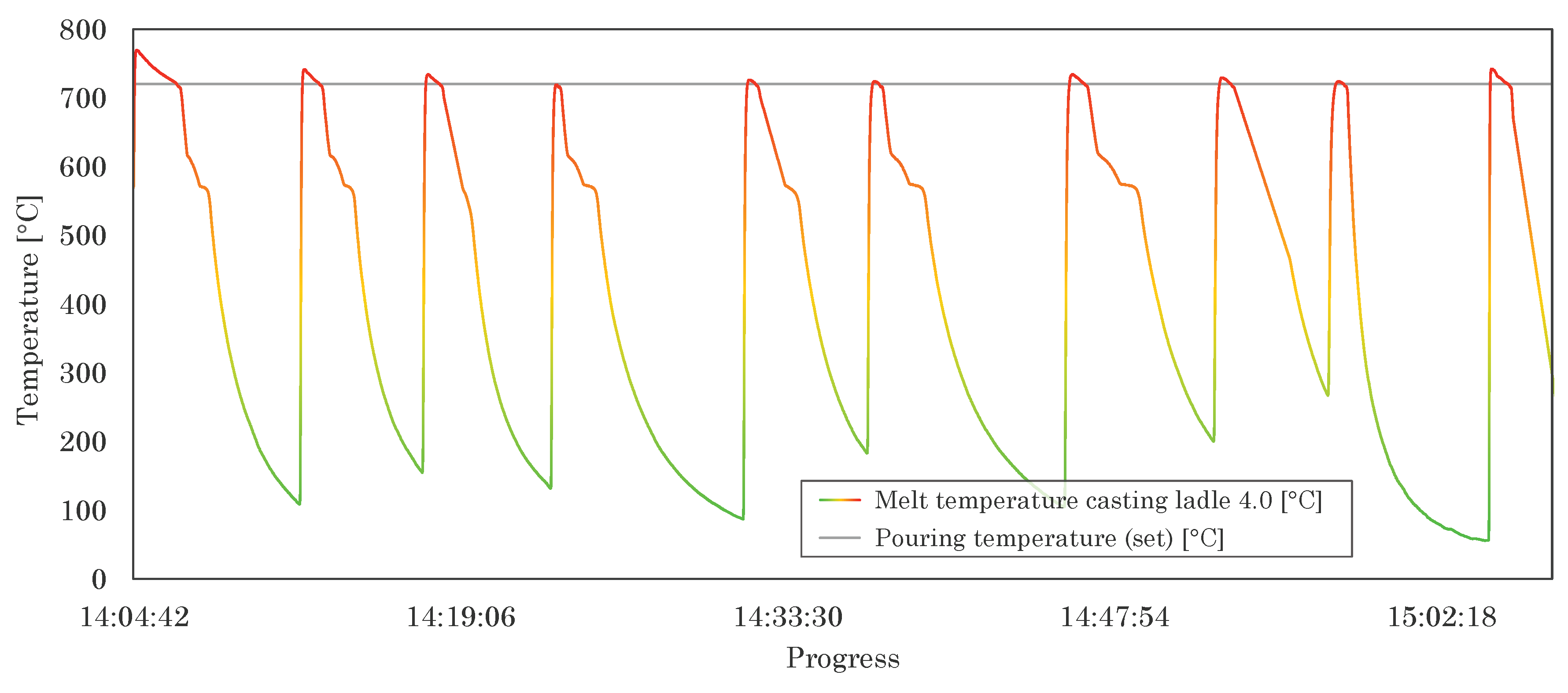
The collected data allow further productivity considerations beyond a detailed process and manufacturing analysis. In this context, Figure 13 illustrates the measured temperature curve in the Casting Ladle 4.0 over an exemplary period. Here, the respective maximum points represent the filling of the ladle with melt, whereas the minima represent the cooling down until immediately before the filling. The distance between adjacent temperature peaks thus provides information about the productive cycle time for manual casting production; the average cycle times between all adjacent temperature peaks provide information about the average cycle time, which is 391 s for this example. The reason for this rather high value is the design of the laboratory furnace. Due to its low melting capacity, it had to be charged with new aluminium ingots after each ladle filling, which took some time to melt and reach the target temperature.
6. Technological Potential Analysis
6.1. Industry 4.0
The sensory process data acquisition of manual casting production allows detailed and, for potential users, new insights into the production process. While the evaluation of individual casting tests was the focus of the investigations described here, the full potential of this application unfolds over the process recording of several weeks, months and years. In addition to the use of temperature and motion sensors, other sensor types can be used, such as atmospheric sensors for recording the ambient temperature, humidity and air pressure [10]. In the case of a process-comprehensive data collection over an adequate period of time, the technological solutions presented so far create for the first time a reliable basis for data science and deep learning approaches for the investigation of dominant correlations in the manual production of castings in the factory or in the laboratory. Even the basis for creating digital twins becomes possible on this basis for manual (casting) production. With further reference to the six stages of the Industry 4.0 development path, the prerequisites for achieving points 5 and 6 can thus be created: predictability and adaptability. It is quite conceivable that, if the necessary data is available and evaluated with the appropriate evaluation tools, plant technology will automatically pick up this data and adapt the process, provided that the employee has been made aware of it. For example, a data analysis could show that a high percentage of rejects is due to a casting temperature that is too low, whereupon the target temperature for the visual release for the employee is increased and the temperature control of the holding furnace is adjusted. Either way, the availability of data allows for faster development times, both in the area of research and development, prototype production or the start-up of new series productions. One of the main advantages, however, is the possibility of applying the solutions presented to and with existing plant technology.
6.2. Quality
While the analysis of the causes of defects in manually produced castings has been extremely difficult up to now, and often impossible in retrospect, the permanent recording and storage of data with the tools used here enables detailed retrospective insights into the quality-relevant production parameters. Seen in this light, the solutions presented enrich the quality management system in the operational context and, with a view to the academic field, allow the assured recording of all relevant process variables, the knowledge of which is of great importance, especially in the case of research and development, and can thus accelerate development processes. By integrating quality-relevant parameters such as concretely measurable casting properties, microstructural properties such as grain size or mechanical parameters, significant process optimisations are possible. However, the data can just as easily be used to calculate processes retrospectively, for example with the help of numerical simulation to better understand the manufacturing circumstances. In this way, development times can be shortened enormously or the occurrence of casting defects can be better understood in retrospect and avoided for the future.
6.3. Operational
Operationally, one of the biggest challenges is the availability of qualified personnel to build and maintain the digital infrastructure. Given the shortage of skilled workers, handcraft businesses are now competing with large tech companies for the available experts. The alternative is to learn the necessary subjects on their own. In the best case, it is possible to assign an employee permanently to this field of activity, who acquires the necessary know-how independently or through training and raises the potential of the individual company. This situation illustrates a development that will be difficult to avoid in the future: that all occupational groups will have to get involved in the development of digitalisation. The present work demonstrates very well the development that manufacturing engineers and academics in this field must address these issues in order to keep pace with the rapid developments.
6.4. Employee
The solutions described - especially the Casting Ladle 4.0 - were primarily developed to support employees in their work. Concrete examples include increasing reproducibility in manual casting production [39] or the induction of new employees, where it is not unusual for them to be lateral entrants. With the help of the Casting Ladle 4.0 and the real-time visualisation of the measurement data, a quick familiarisation can take place. It is therefore suitable for basic and advanced training as well as the further development of foundry specialists and can increase the attractiveness of the occupational field through the possibility of applying modern technologies.
While the solutions shown can be used for the benefit of employees, they can also be used against them. The process transparency that goes hand in hand with data collection is accompanied by a visibility of the employee that has not existed in this occupational field so far (keyword transparent employee). This circumstance requires the sensitive handling of personal data and clear guidelines on how to deal with it. Particularly against the backdrop of rapidly advancing technological developments in the field of automation and artificial intelligence, greater emphasis must be placed on, and consideration given to how people can be protected despite the advantages associated with these developments and are not at the mercy of the data.
7. Conclussion
This paper has shown the insights and potentials that go hand in hand with comprehensive process data acquisition during manual casting production. Starting with a presentation of the necessary process steps of casting production and a critical examination of the manual casting process, the potentials of digitalisation and Industry 4.0 for this process were presented. The focus of the work was the conceptual and practically tested presentation of a solution for comprehensive process data acquisition as well as the subsequent analysis of the collected data during manual casting acquisition within the framework of Industry 5.0. The evaluation allowed detailed insights into the entire process sequence and thus laid the foundation for well-founded data science and deep learning approaches. Subsequently, technological potentials with regard to Industry 4.0/5.0, casting quality and foundry operations were discussed without disregarding the advantages and disadvantages of such solutions for the employee. In summary, the paper shows which advantages digitalisation and Industry 4.0/5.0 also offer for small and medium-sized foundries with a high proportion of manually performed work steps and which hardware and software components are required for their successful implementation.
Author Contributions
Conceptualization, E.R.; methodology, E.R.; software, E.R..; validation, E.R.; formal analysis, E.R.; investigation, E.R.; resources, E.R.; data curation, E.R.; writing—original draft preparation, E.R.; writing—review and editing, E.R.; visualization, E.R.; supervision, E.R.; project administration, E.R.; funding acquisition, E.R.; funding acquisition, E.R.
Funding
The authors would like to thank the Federal Ministry for EconomicAffairs and Climate Action and the Central Innovation Programme forsmall and medium-sized enterprises (ZIM project funding referencenumber KK5053202SU0) for its financial support.
Conflicts of Interest
The author declare no conflicts of interest.
Abbreviations
The following abbreviations are used in this manuscript:
| MQTT | MQTT is the actual name of the communication protocol |
| OEM | Original Equipment Manufacturers |
| SME | Small and medium-sized enterprises |
References
- Ostermann, F. Anwendungstechnologie Aluminiumm; Springer: Berlin Heidelberg, 2014. [Google Scholar]
- A brief guide to casting metals. Treatstock, 2023.
- Stefanescu, D.M. A succinct history of metalcasting knowledge. International Journal of Metalcasting 2023. [Google Scholar] [CrossRef]
- Statistic code 42271-0006. Distribution of companies in the foundry industry in Germany by employee size class in 2020. Statistisches Bundesamt (engl. German Federal Office of Statistics), 2021.
- Meyer, L.; Reker, J. Industrie 4.0 im Mittelstand (engl. Industry 4.0 in the SME sector). Deloitte 2016. [Google Scholar]
- Schröder, C. Herausforderungen von Industrie 4.0 für den Mittelstand (engl. Challenges of Industry 4.0 for SMEs). Friedrich-Ebert-Stiftung (engl. Friedrich Ebert Foundation), 2016. [Google Scholar]
- Von Wascinski, L.; Weiß, M.; Tilebein, M. Industrie 4.0 für die Textil- und Bekleidungsindustrie (engl. Industry 4.0 for the textile and clothing industry). KMU 4.0 - Digitale Transformation in kleinen und mittelständischen Unternehmen (engl. SME 4.0 - Digital transformation in small and medium-sized enterprises), 2018. [Google Scholar]
- Kinkel, S.; Beiner, S.; Schäfer, A.; Heimberger, H.; Jäger, A. Wertschöpfungspotenziale 4.0 (engl. value creation potential). Institut für Produktionserhaltung (engl. Institute for Production Maintenance), 2021. [Google Scholar]
- Bischoff, J. Erschließen der Potenziale der Anwendung von ,Industrie 4.0‘ im Mittelstand (engl. Unlocking the potential of the application of ’Industry 4.0’ in SMEs). agiplan GmbH, 2015. [Google Scholar]
- Riedel, E. MQTT protocol for SME foundries: potential as an entry point into industry 4.0, process transparency and sustainability. Procedia CIRP 105, 2022. [Google Scholar]
- Scharf, S.; Sander, B.; Kujath, M.; Richter, H.; Riedel, E.; Stein, H.; tom Felde, J. FOUNDRY 4.0: An innovative technology for sustainable and flexible process design in foundries. Procedia CIRP 98 2021. [Google Scholar] [CrossRef]
- Campbell, J. Castings, Second Edition (Castings). Butterworth-Heinemann, 2023. [Google Scholar]
- Bührig-Polaczek, A. Handbuch Urformen (engl. handbook primary forming). Carl Hanser GmbH & Company, 2013. [Google Scholar]
- Jang, H.S.; Kang, H.J.; Park, J.Y.; Choi, Y.S.; Shin, S. Effects of casting conditions for reduced pressure test on melt quality of al-si alloy. Metals 2020. [Google Scholar] [CrossRef]
- Wallace, J.F.; Schwam, D.; Hong, W. Mold materials for permanent mold casting of aluminium alloys - final report. Technical report. Case Western Reserve University 2001. [Google Scholar]
- Kan, M. Determination of the casting-mold interface heat transfer coefficient for numerically die-casting process depending on different mold temperatures. Journal of Mechanical Science and Technology 2022. [Google Scholar] [CrossRef]
- Emre, Y.; Çolak, M. Modeling the effect of pour height, casting and mold heating conditions for the analysis of fluidity of different section thicknesses in die mold casting of Al12Si alloys. Journal of Science and Technology 2022. [Google Scholar]
- Chelladurai, C.; Mohan, N.S.; Hariharashayee, D.; Manikandan, S.; Sivaperumal, P. Analyzing the casting defects in small scale casting industry. Materials Today: Proceedings 2021. [Google Scholar] [CrossRef]
- Jarfors, A.E.W.; Seifeddine, S. Metal casting. In Handbook of Manufacturing Engineering and Technology; 2014. [Google Scholar]
- Shabestari, S.G.; Shahri, F. Influence of modification, solidification conditions and heat treatment on the microstructure and mechanical properties of A356 aluminum alloy. Journal of Materials Science 2004. [Google Scholar] [CrossRef]
- Wang, M.; Song, Y.; Wang, P.; Chen, Y.; Sun, T. Grinding/cutting technology and equipment of multi-scale casting parts. Chinese Journal of Mechanical Engineering 2022. [Google Scholar] [CrossRef]
- Ndaliman, M.; Pius, A. Behavior of aluminum alloy castings under different pouring temperatures and speeds. Leonardo Electronic Journal of Practices and Technologies 2007. [Google Scholar]
- Pang, S.; Wu, G.; Liu, W.; Zhang, L.; Zhang, Y.; Conrad, H.; Ding, W. Influence of pouring temperature on solidification behavior, microstructure and mechanical properties of sand-cast Mg-10Gd-3Y-0.4Zr alloy. Transactions of Nonferrous Metals Society of China 2015. [Google Scholar] [CrossRef]
- Ahmad, R.; Talib, N.A.; Asmael, M.B.A. Effect of pouring temperature on microstructure properties of Al-Si LM6 alloy sand casting. Applied Mechanics and Materials 2013. [Google Scholar] [CrossRef]
- Li, L.; Li, D.; Gao, J.; Zhang, Y.; Kang, Y. Influence of mold temperature on microstructure and shrinkage porosity of the A357 alloys in gravity die casting. Lecture Notes in Mechanical Engineering 2018. [Google Scholar]
- Ferreira, A.F.; Chrisóstimo, W.B.; Sales, R. C:; Garção, W.J.L.; de Paula Sousa, N. Effect of pouring temperature on microstructure and microsegregation of as-cast aluminum alloy. The International Journal of Advanced Manufacturing Technology 2019. [Google Scholar] [CrossRef]
- Pulisheru, K.S.; Birru, A.K. Influence of pouring temperature on fluidity of al–cu cast alloy: analyses using casting simulation software. Lecture Notes on Multidisciplinary Industrial Engineering 2019. [Google Scholar]
- Taha, A.S.; Hammad, F.H. Application of the Hall-Petch relation to microhardness measurements on Al, Cu, Al-MD 105, and Al-Cu alloys. physica status solidi (a) 1990. [Google Scholar] [CrossRef]
- Smith, W.F. Foundations of materials science and engineering; McGraw-Hill, 2005. [Google Scholar]
- Motoyama, Y.; Iwamoto, K.; Tokunaga, H.; Okane, T. Measuring hand-pouring motion in casting process using augmented reality marker tracking. The International Journal of Advanced Manufacturing Technology 2020. [Google Scholar] [CrossRef]
- Wang, G.; Zhao, G.; Wang, X. Development and evaluation of a new rapid mold heating and cooling method for rapid heat cycle molding. International Journal of Heat and Mass Transfer 2014. [Google Scholar] [CrossRef]
- Schuh, G.; Anderl, R.; Gausemeier, J.; ten Hompel, M.; Wahlster, W. Industrie 4.0 maturity index - managing the digital transformation of companies. acatech STUDY, 2018. [Google Scholar]
- Papulová, Z.; Gažová, A.; Šufliarský, L. Implementation of automation technologies of industry 4.0 in automotive manufacturing companies. Procedia Computer Science 2022. [Google Scholar] [CrossRef]
- Mon, A.; Del Giorgio, H.R. Analysis of industry 4.0 products in small and medium enterprises. Procedia Computer Science 2022. [Google Scholar] [CrossRef]
- Naciri, L.; Mouhib, Z.; Gallab, M.; Nali, M.; Abbou, R.; Kebe, A. Lean and industry 4.0: A leading harmony. Procedia Computer Science 2022. [Google Scholar] [CrossRef]
- European Commission. Directorate General for Research and Innovation. Industry 5.0: human centric, sustainable and resilient. Publications Office, 2020.
- European Commission. Directorate General for Research and Innovation. Industry 5.0: towards a sustainable, human centric and resilient European industry. Publications Office, 2021.
- European Commission. Directorate General for Research and Innovation. Industry 5.0, a transformative vision for Europe: governing systemic transformations towards a sustainable industry. Publications Office, 2021.
- Riedel, E.; Ahmed, M.; Hellmann, B.; Horn, I. Foundry 4.0: digitally recordable casting ladle for the application of industry 4.0-ready manual casting processes. Procedia CIRP, 2023. [Google Scholar]
- Desbiens, F. MQTT. Building Enterprise IoT Solutions with Eclipse IoT Technologies 2022. [Google Scholar]
- Zimányi, E.; Naqvi, S.N.Z.; Yfantidou, S. Time series databases and influxdb. Technical report, Universite libre de Bruxelles 2017. [Google Scholar]
- Kanagachidambaresan, G.R.; Bharathi, N.; Yfantidou, S. Introduction to node-RED and industrial dashboard design. Sensors and Protocols for Industry 4.0 2023. [Google Scholar]
- Chakraborty, M.; Kundan, A.P. Grafana. Monitoring Cloud-Native Applications, 2021. [Google Scholar]
- Leens, F. An introduction to I2C and SPI protocols. IEEE Instrumentation & Measurement Magazine 2009. [Google Scholar]
Figure 1.
Schematic illustration of the established process chain for aluminium casting production [10].
Figure 1.
Schematic illustration of the established process chain for aluminium casting production [10].
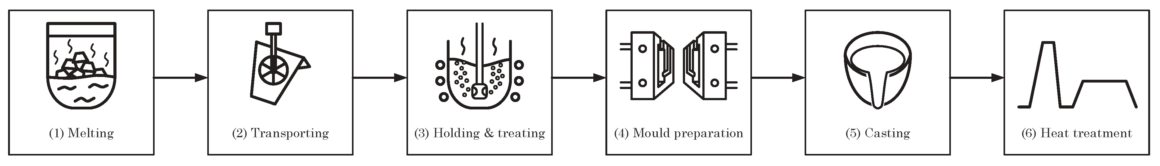
Figure 2.
Schematic illustration of the applied information technology infrastructure.
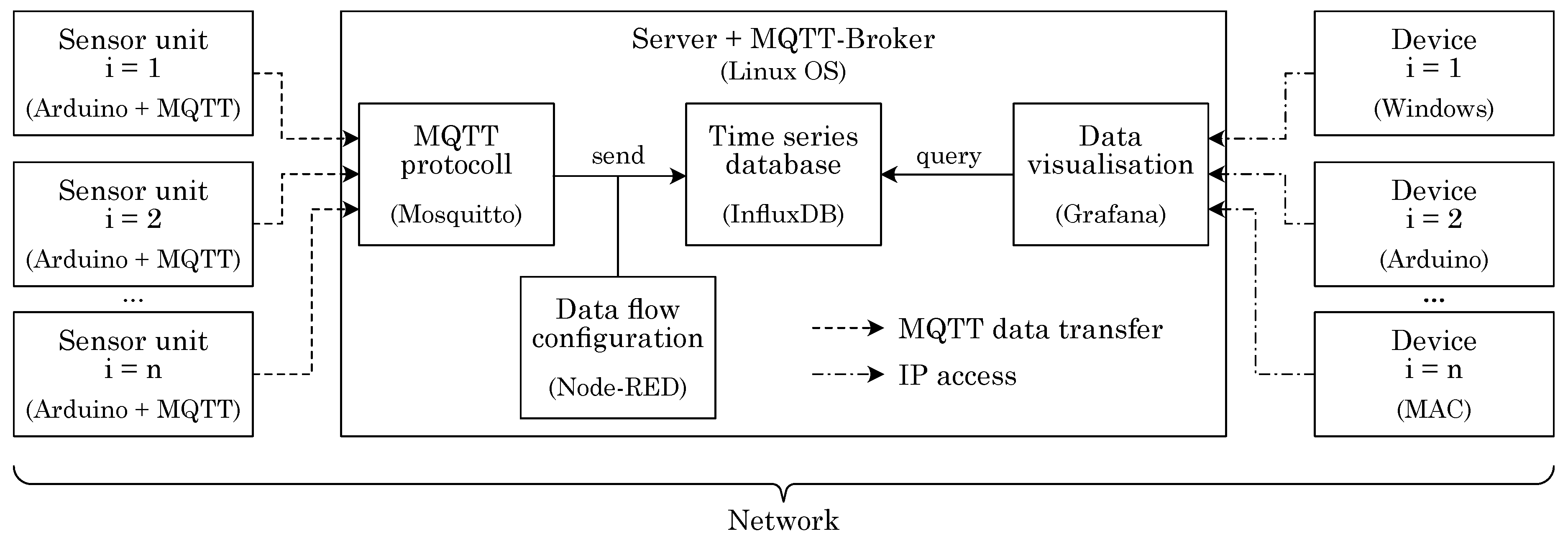
Figure 3.
Schematic structure of the sensor units used for the experimental setup.
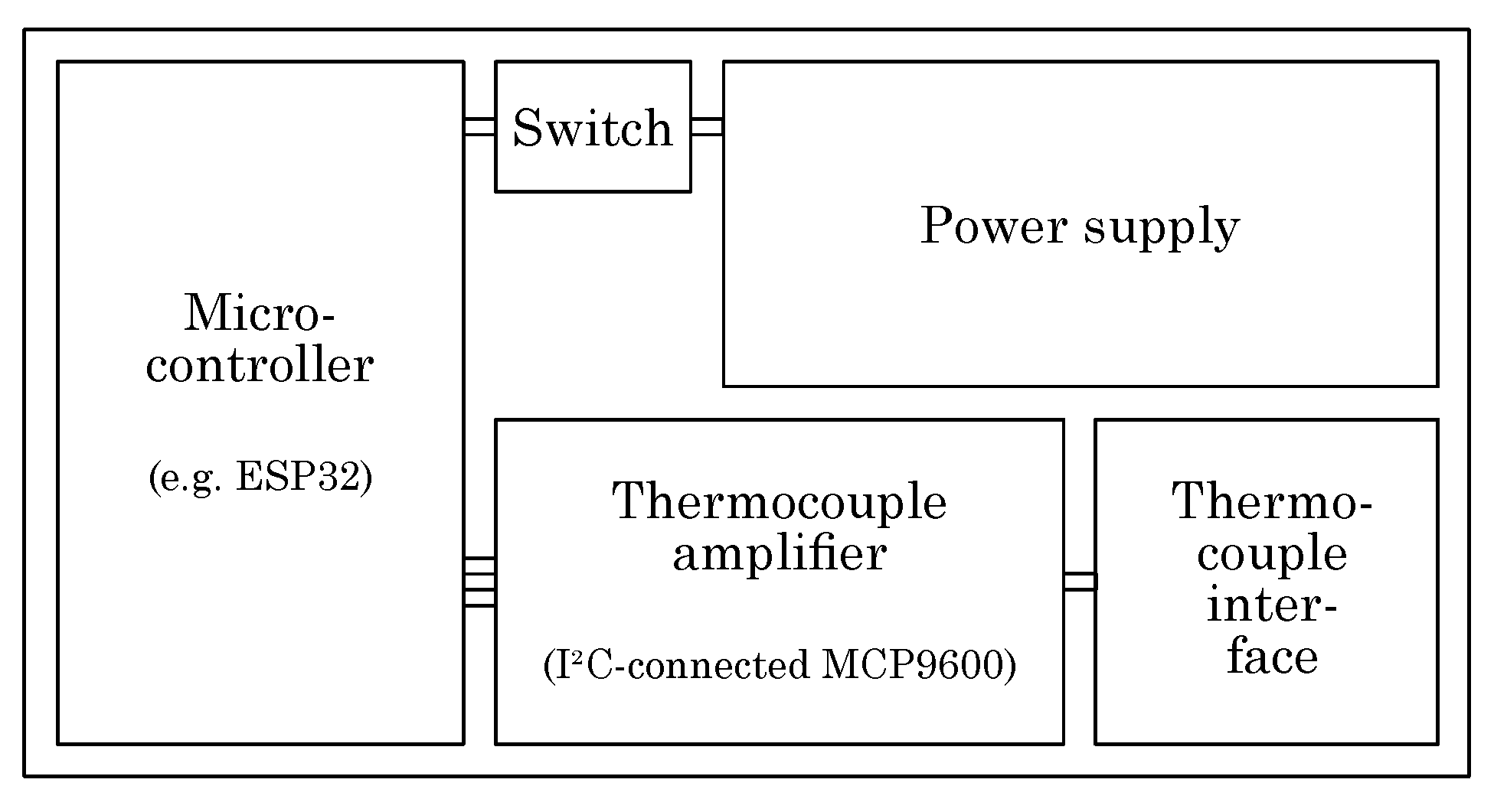
Figure 4.
Schematic design of the Casting Ladle 4.0 used for the experiments.
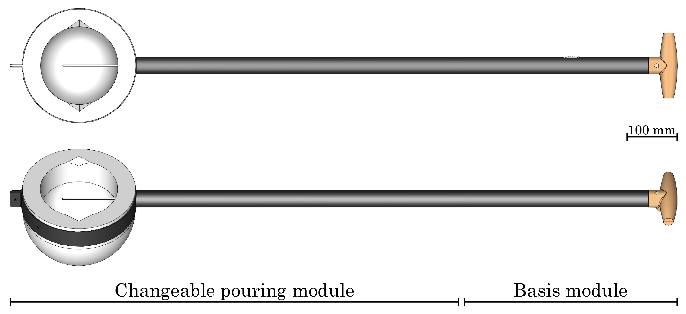
Figure 5.
components used for digital process recording and visualisation.
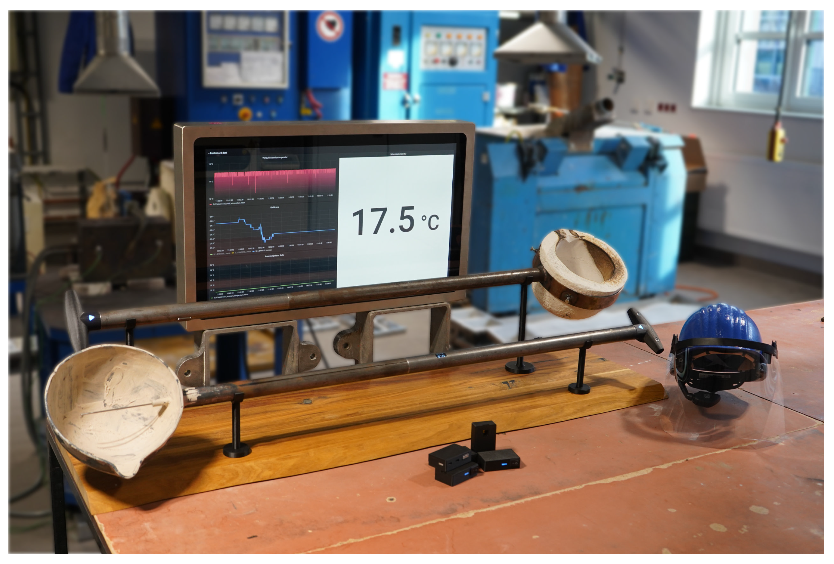
Figure 6.
Schematic representation of the experimental setup (not to scale): 1) tilting melting and holding furnace, 2) sensor box 1 - temperature measurement of furnace, 3) mould, 4) sensor box 2 - temperature measurement of mould, 5) computer (broker), 6) monitor for visualisation of measurement data, 7) foundryman, 8) Casting Ladle 4.0.
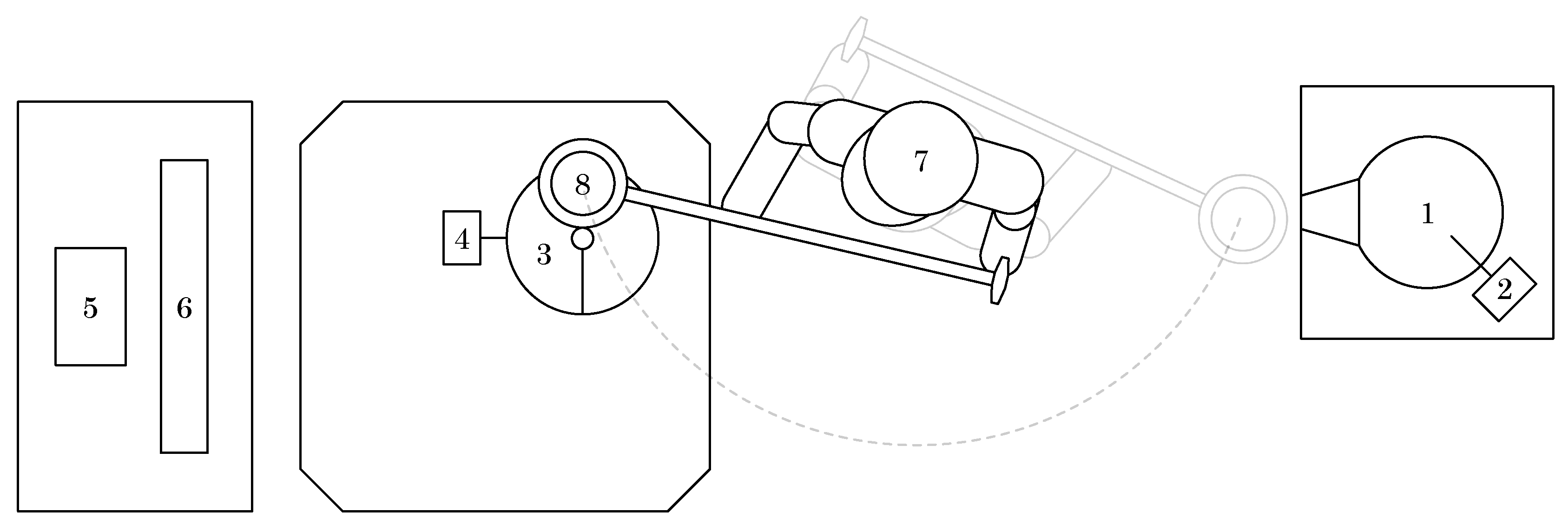
Figure 7.
Experimental testing of the sensory infrastructure for recording the relevant process data in manual casting production.
Figure 7.
Experimental testing of the sensory infrastructure for recording the relevant process data in manual casting production.
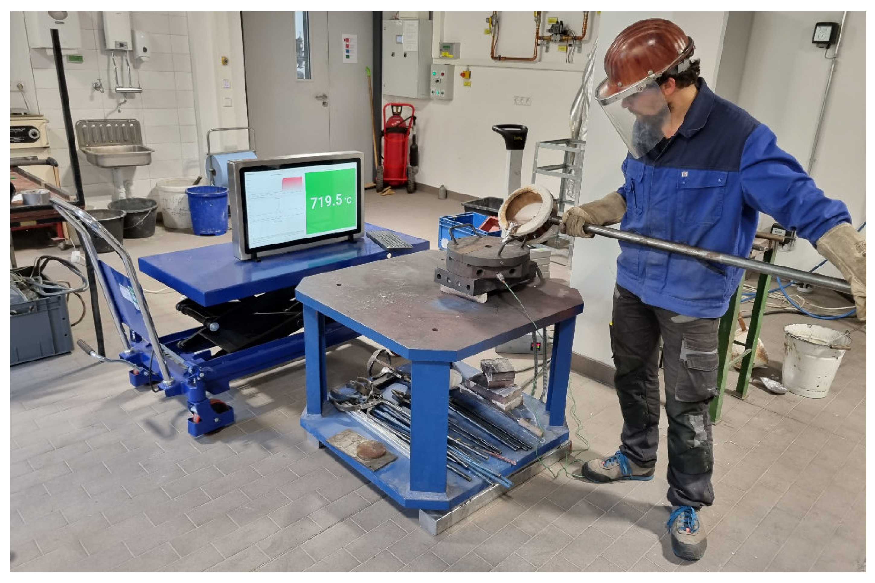
Figure 8.
Evaluation of casting parameters recorded with Casting Ladle 4.0 and sensor units: 1) removal of the thermocouple from the melting furnace, 2) start of ladle filling, 3) measurement of the actual temperature, 4) repositioning of the thermocouple in the melting furnace and end of ladle filling at the latest, 5) positioning of the ladle in preparation for casting, 6) reaching of the defined target pouring temperature and start of mould filling, 7) end of the pouring process, 8) temperature increase of the mould due to heat influence of the higher melt temperature compared to the mould temperature, 9) return of excess melt to the holding furnace.
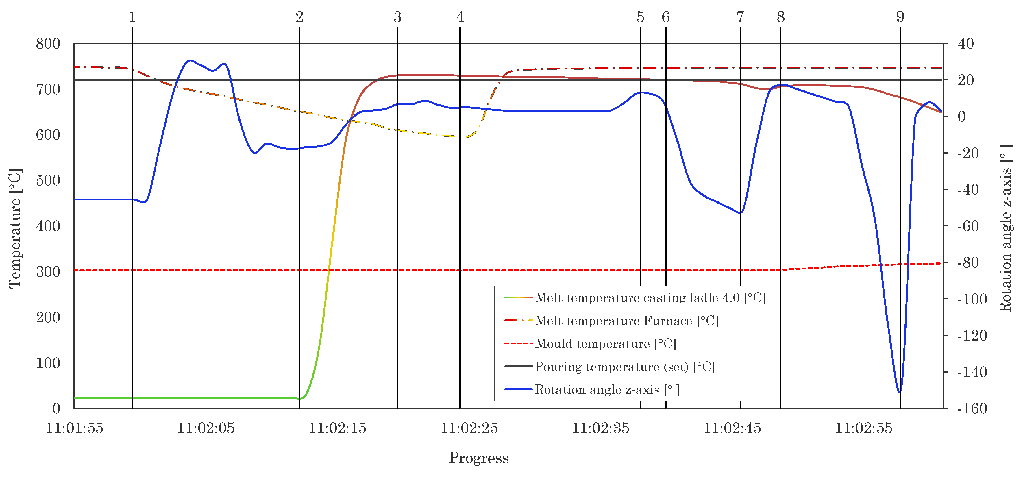
Figure 9.
Evaluation of casting parameters recorded with Casting Ladle 4.0: a) Rotation of the casting ladle in z-axis during mould filling b) Melt temperature curve during mould filling. The period between points 6 and 7 corresponds to the duration of the mould filling, here 6 seconds (rounded up).
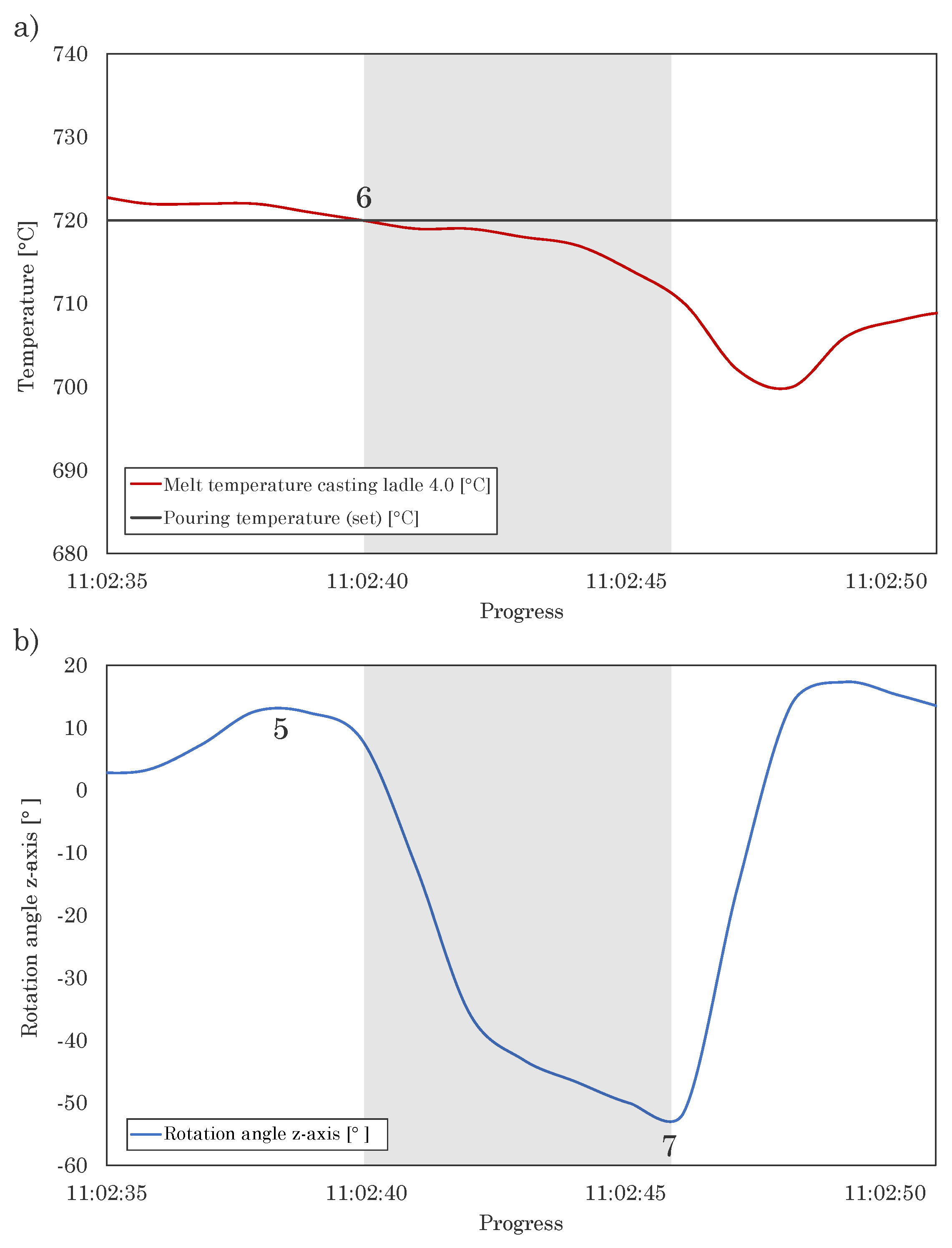
Figure 10.
Evaluation and comparison of different pouring curves, recorded with the Casting Ladle 4.0.
Figure 10.
Evaluation and comparison of different pouring curves, recorded with the Casting Ladle 4.0.
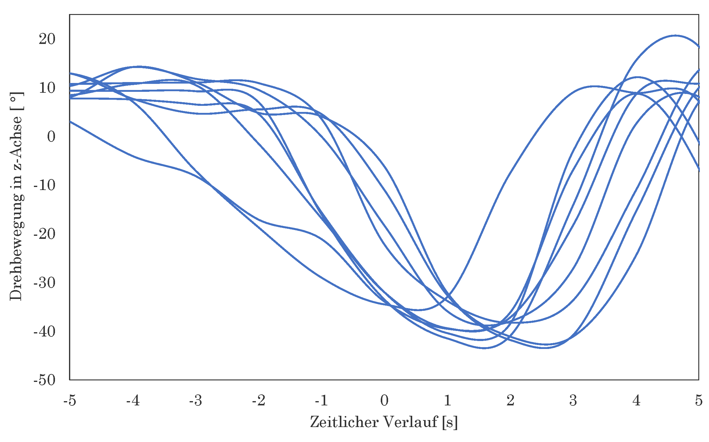
Figure 11.
Illustration of the influence of the filling level of the ladle on the initial tilt angle during mould filling.
Figure 11.
Illustration of the influence of the filling level of the ladle on the initial tilt angle during mould filling.
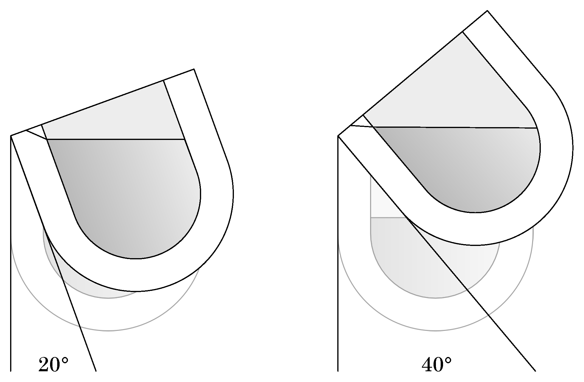
Figure 12.
Exemplary comparison of the pouring curve and the temperature curve of two different pouring processes.
Figure 12.
Exemplary comparison of the pouring curve and the temperature curve of two different pouring processes.
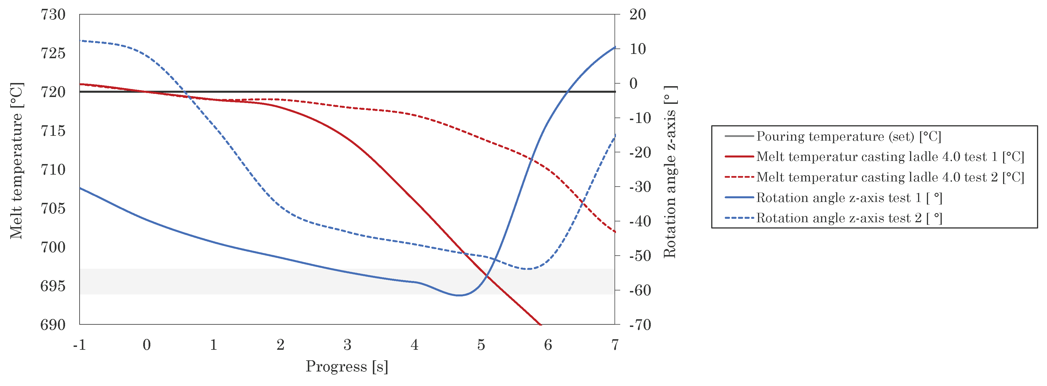
Figure 13.
Analysis of the temperature curve measured over several consecutive casting processes in the Casting Ladle 4.0.
Figure 13.
Analysis of the temperature curve measured over several consecutive casting processes in the Casting Ladle 4.0.
Disclaimer/Publisher’s Note: The statements, opinions and data contained in all publications are solely those of the individual author(s) and contributor(s) and not of MDPI and/or the editor(s). MDPI and/or the editor(s) disclaim responsibility for any injury to people or property resulting from any ideas, methods, instructions or products referred to in the content. |
© 2025 by the authors. Licensee MDPI, Basel, Switzerland. This article is an open access article distributed under the terms and conditions of the Creative Commons Attribution (CC BY) license (http://creativecommons.org/licenses/by/4.0/).
Copyright: This open access article is published under a Creative Commons CC BY 4.0 license, which permit the free download, distribution, and reuse, provided that the author and preprint are cited in any reuse.


