Submitted:
13 March 2025
Posted:
14 March 2025
You are already at the latest version
Abstract
Due to the highly demanding operating conditions of the Modular Multilevel Converter (MMC), as well as its inherently complex structure, electric field analysis of the MMC valve is crucial for the safe and stable operation of MMC-HVDC (MMC high voltage direct current) transmission systems. In this paper, a high-speed modeling method for MMC valve based on data derivation is proposed. Firstly, the relationship between the MMC valve electric field calculation model parameters and the MMC-HVDC transmission system parameters was studied. Based on this, the data derivation system for the electric field calculation model parameters of all components of MMC valve was established. Modeling parameters database based on empirical knowledge is also used in the calculation process of the data derivation system. The output model parameter matrix includes the geometric parameters, position parameters, and electrical parameters of the components. Based on the output matrix, the electric field calculation model of the converter valve can be quickly generated. Furthermore, to improve the accuracy of the calculations and reduce computation time, a discrete modeling method that combines mesh optimization was proposed. In the process of discretized electric field modeling, a mesh division influence factor based on the accuracy of electric field calculation is proposed. By adjusting the mesh division influence factor during the electric field calculation, the accuracy of the electric field calculation can be optimized rapidly. Finally, the effectiveness and practicality of the high-speed modeling method for MMC valve are verified through comprehensive case studies conducted on the ±320kV onshore MMC-HVDC valve. It is demonstrated that the high-speed modeling method proposed in this paper can significantly reduce the modeling time of the converter valve and greatly improve the accuracy of electric field calculation.
Keywords:
Modular multilevel converter (MMC)
; data derivation
; electric field calculation modeling parameters
; discretization modeling
1. Introduction
Because of the manufacturing or complex operating conditions, there might be some insulation failure or defects in the insulation of the MMC valve. The analysis of the electric field in MMC valve has become extremely important, especially, MMC-HVDC system are used widely in recent years. With the continuous increase in voltage and capacity, the MMC valve, as a core component of the MMC-HVDC transmission system, is facing increasing challenges [1,2,3,4]. The MMC valve is subjected to highly complex and demanding current and voltage conditions during operation. Consequently, the electric field characteristics of MMC valve have a significant impact on the safety and stability of the MMC HVDC transmission systems. In particular, under fault conditions with impulse excitation, the distributed parameters of the MMC valves, especially the stray capacitance, can have a severe impact on the system. In summary, the electric field accurate analysis of MMC valve is of significant importance for the design of the MMC valve and the MMC-HVDC system [5,6,7]. Research on the fault characteristics of MMC valve based on electric field analysis continues to be a hot topic in the industry.
For the calculation of the electric field in the valve hall, reference [8] proposes a simplified calculation model of the radiative near field of the electric field in the circuit breaker valve hall. To address the calculation of stray capacitance parameters in the converter valve tower, reference [9] presents a simplified approach for MMC valve, employing the finite element method to compute the stray capacitances. Similarly, reference [10] adopts the simplified BEM to gain the parasitic capacitance parameters within converter valve. In order predicting the radiated EMI, the converter valve tower is model as a complex antenna structure with the output voltage of each sub-module as the excitation in reference [11]. In reference [12], through simplification FEM model of the valve tower in ANSYS Q3D, the capacitances are calculated. However, in the analysis of electric field modelling method in these articles, both the insulators and the shape of the outer conductors are ignored, which will significantly reduce the accuracy of the electric field calculation. Meanwhile, in the model process of the converter valve, the conventional import method or the re-establishment of the electric field model based on the mechanical model is adopted. This will result in a very long time required for the establishment of the converter valve electric field model.
Conventional modeling methods for MMC valve electric fields suffer from long modeling times and low accuracy. In this paper, a high-speed modeling method for MMC valve is proposed to overcome these drawbacks. The data derivation is used to generate multiple sets of parameters from a limited number of system input parameters (three to four). These derived parameters are then utilized to establish the electric field analysis model for the MMC valve. Firstly, the relationship between the MMC valve electric field calculation model parameters and the MMC-HVDC transmission system parameters was studied. Based on this, the data derivation system for the electric field calculation model parameters of all components of MMC valve was established. Modeling parameters database based on empirical knowledge is also used in the calculation process of the data derivation system. Empirical knowledge is used to constrain and correct the parameters. The output model parameter matrix includes the geometric parameters, position parameters, and electrical parameters of the components. Based on the output matrix, the electric field calculation model of the converter valve can be quickly generated. Furthermore, to improve the accuracy of the calculations and reduce computation time, a discrete modeling method that combines mesh optimization was proposed. In the process of discretized electric field modeling, a mesh division influence factor based on the accuracy of electric field calculation is proposed. By adjusting the mesh division influence factor during the electric field calculation, the accuracy of the electric field calculation can be optimized rapidly. Finally, the effectiveness and practicality of the high-speed modeling method for MMC valve are verified through comprehensive case studies conducted on the ±320kV onshore MMC-HVDC valve. By comparing the modeling times, calculation error rate and calculation times, it was confirmed that the method described in this paper has significant advantages.
2. High-Speed Modeling Method for MMC Valve
The MMC HVDC power transmission system has been put into practice in many projects [13,14,15]. The MMC system schematic diagram and MMC valve in hall are illustrated in Figure 1.
The design data and operational observation data for the MMC system are all circuit parameters such as voltage and current. In the operating environment of the valve hall, the insulation characteristics of the MMC valve need to be obtained through electric field calculation. The conventional electric field analysis process of the MMC valve, which is widely used in engineering practice, is shown in Figure 2.
As shown in Figure 2, the conventional electric field modeling method involves multiple departments and is time-consuming. When transitioning from the mechanical model to the electric field analysis model, simplifications are made to adjust the electric field analysis.
The importation of models may introduce errors, thereby reducing the computational accuracy. Moreover, if system parameters are updated or adjusted during the analysis, the mechanical model must be re-established. The conventional approach results in a lengthy analysis cycle for the converter valve's electric field, with difficulties in controlling the computational accuracy [16,17,18].
To enhance the efficiency and accuracy of the electric field analysis of the MMC valve, it is necessary to establish models based on the requirements of electric field analysis and the characteristics of the MMC-HVDC power transmission system. The high-speed modeling method for electric field analysis of the MMC valve is illustrated in Figure 3.
As shown in Figure 3, the high-speed modeling for the electric field analysis of the MMC valve used data derivation to generate multiple modeling datasets from limited input data. Within the data derivation system, the parameters necessary for the modeling process of the MMC valve are computed. The high-speed modeling method proposed in this paper can significantly reduce the time required for modeling. The continuing in this section will delve into the fundamental theories of electric field modeling that underpin the data derivation system.
According to the fundamental principles of electric fields, the electric equilibrium characteristics of a conductor reveal that the inner surface of a metallic conductor has no charge distribution, and the electric field within an air-filled cavity is zero, with a uniform potential throughout. The shape of the internal cavity does not influence the external electric field distribution of the conductor. The curvature of the conductor's outer surface significantly affects the charge distribution and electric field. Higher curvature reduces the repulsive force between charges, leading to higher charge density and a more concentrated electric field. Conversely, lower curvature results in a more uniform electric field distribution. Therefore, while the shape of the conductor's outer surface strongly impacts the electric field distribution, the internal cavity and its shape have no effect on the external electric field.
According to Gauss's law, the electric field strength produced by multiple charged bodies in space exhibits superposition. The electric field generated by multiple conductors at a point in space can be obtained by vector summing the electric fields produced by each conductor at that point. The principle of electric field equivalence between discrete conductors and a continuous conductor is illustrated in the Figure 4.
As shown in Figure 4, the electric field distribution of a continuous conductor is consistent with that of discrete equipotential conductors in space.
3. Data Derivation System of Electric Field Modeling
The MMC valve is a core component in the actual operation of the MMC-HVDC power transmission system. As a high-voltage, high-capacity power electronic device, the structure of the MMC valve is determined by the system parameters [19,20]. By conducting a theoretical analysis of the process of establishing the electric field model of the MMC valve, and combining it with the relationship analysis of the MMC valve and the main circuit parameters.
The data derivation system for the electric field modeling parameters of the MMC valve is defined as:
In the Equation (1), Xin and Yout are the input and output matrix, Φ(x) are data derivation system, Udc is the DC voltage of the MMC, Pdc and Q are the active power and reactive power of MMC. The data derivation system matrix Φ(x) and output Yout are defined as:
In the Equation (2), Fsm(x) is the submodule parameters calculation matrix, Fsheild(x) is the shielding cover parameters calculation matrix, Finsulator(x) is the insulator parameters calculation matrix, Fbeam(x) is the support frame parameters calculation matrix, Fring(x) is the grading ring parameters calculation matrix, Ysm is the modeling parameters of submodules, Ysheild is the modeling parameters of shielding covers, Yinsulator is the modeling parameters of insulators, Ybeam is the modeling parameters matrix of support frames, Yring is the modeling parameters of grading rings.
According to the principles of electric field calculation for MMC valve and the analysis of key factors, the electric field modeling parameters for MMC valve are categorized into five distinct categories. The data derivation system Φ(x) and the modeling parameters data Yout are structured accordingly. The following sections provide a detailed analysis of each of these five categories.
3.1. Multidimensional Array Modeling of Submodule
The submodule is the fundamental building block of the MMC valve and constitutes its core component of the MMC valve. Each converter valve is typically composed of multiple submodules. The parameter matrix of the submodules is defined as:
In the Equation (3), Ysmij is the modeling parameters matrix of the submodule j in layer i of the MMC valve, MSN denotes the number of submodules in each layer of the MMC valve, and CLT denotes the number of layers in the MMC valve.
As shown in Equation (3), the electric field modeling parameters of each submodule consist of three distinct sets of parameters, the electrical parameter matrix E(sm), the spatial geometric parameter matrix G(sm), and the spatial location matrix SP(sm).
Due to the metallic conductor nature of the sub-module's outer casing, the sub-module acquires a certain electric potential during the operation of the MMC valve, with the entire outer casing forming an equipotential body. The electrical parameter matrix E(sm) of the submodule is defined as:
In the Equation (4), GVsmij is electric potential of the submodule ij in the valve, NS denotes the voltage coefficient, usmd is the rated voltage of submodule, GVT is the electric potential of the first submodule in the valve, MCsm is material properties of the submodule shell.
The submodule is composed of power devices, capacitors, and other components. Once the type of power device and the parameters of the capacitor are specified, the geometric dimensions of the submodule can be determined. The geometric parameter matrix of the submodule is defined as:
In the Equation (5), EC(sm) is a computational matrix for the geometric dimensions of the submodule, Csm is rated capacitance of the submodule, UcmN is the rated voltage of Csm, Form is the shape structure of the submodule. The dimensions X0, Y0 and Z0 denote the preliminary geometric sizes of the submodule.
The shape structure of the submodule capacitor is obtained from the capacitor manufacturer and typically has a limited range of options. The preliminary geometric sizes of the submodule are generally provided by the structural design engineers. The calculation of geometric parameters adopts a database format, where the geometric parameters of the submodule are determined based on its rated voltage and capacitance.
The calculation methods for the rated voltage of the submodule and the rated voltage of the capacitor are defined as:
In the Equation (6), DB is the parameter database for high-capacity, fully-controlled power electronic devices (such as IGBTs), uPSD is the voltage rating of the device, Kcu is the calculation coefficient for the rated voltage of capacitor.
The submodules are arranged in the MMC valve according to the wiring sequence. The positional parameters of the submodules are determined by the layout method of the valve tower. The calculation method for the positional parameters of the submodules is defined as:
In the Equation (7), Xsm11, Ysm11 and Zsm11 are the coordinates of the first submodule in the MMC valve, xmij, ymij, zmij are the displacement coordinates of submodule ij relative to the first submodule in the MMC valve. These displacement coordinates can be determined based on the rated voltage of the sub-module and their layout configuration.
3.2. Multidimensional Array Modeling of Shielding Cover
The shielding cover significantly influences the electric field distribution of the MMC valve. The shielding covers of the MMC valve generally consist of two types, one with curved shapes located at the four corners, and the other with flat-plate shapes positioned at other locations. The electric field calculation parameters matrix of the MMC valve shielding covers are defined as:
In the Equation (8), YshieldC denotes the arc-shaped shielding covers at the four corners of each layer, YshieldP denotes the flat-plate shielding covers, LT is the number of layers in the MMC valve, NSC is the number of shielding covers in one layer of the MMC valve.
The electric field modeling parameters of each shielding cover consist of three distinct sets of parameters. The modeling parameters matric of each shield are defined as:
In the Equation (9), YshieldCij denotesthe modeling parameters of the corner shielding cover j in the layer i of the MMC valve, YshieldPij is the modeling parameters of flat-plate shielding cover j in the layer i of the MMC valve.
Shielding covers are arranged externally on the MMC valve and serves the functions of electromagnetic shielding and protection. The shielding covers are connected to the nearby submodules, forming an equipotential connection.
The electrical parameter matrix E(shield) of the shield covers is defined as:
In the Equation (10), GVsmij is electric potential of the shield cover ij in the valve, DS is voltage coefficient, MCshiled is material properties of the shield covers.
During the operation of the MMC valve, the shielding cover neither carries current nor performs power transmission. It protects the MMC valve by optimizing the electric field distribution, which is the primary objective of its design.
The geometric parameter matrix of the shield is defined as:
In the Equation (11), EC(shield C) is a computational matrix for the geometric dimensions of the corner shielding cover, Form is the shape structure of the shield cover. The dimensions X0, Y0 and Z0 denote the preliminary geometric sizes of the shield cover, ALR are the curvature parameters of the shielding cover.
The geometric parameters of the shielding covers are using a database format. For the MMC valve, the limited variety of shielding cover styles simplifies database establishment. The positional parameters are determined by the layout method of the valve tower. The calculation method for the positional parameters of the shield cover is defined as:
In the Equation (12), Xsc11, Ysc11 and Zsc11 are the coordinates of the first shiled cover in the MMC valve, xmij, ymij, zmij are the displacement coordinates of shielding cover ij relative to the first shielding cover in the MMC valve.
3.3. Multidimensional Array Modeling of Grading Ring
Two voltage equalization rings are arranged at the top of the MMC valve, serving the dual functions of voltage equalization and providing connections for the incoming and outgoing lines of the MMC valve. The modeling parameters matric for the equalization rings are defined as:
In the Equation (13), Yring1 and Yring2 are the modeling parameters of the two voltage equalization ring, GVring is electric potential of the ring, Nsm is voltage coefficient, GV1 is the electric potential of ring 1. The electric field modeling parameters of top voltage equalization rings are also composed of three sets of parameters.
The voltage equalization rings at the top of the MMC valve are typically composed of two C-shaped tubular structures. The geometric parameters matrix and positional parameters matrix are defined as:
In the Equation (14), EC(ring) is a computational matrix for the geometric dimensions of the voltage equalization ring, Form is the shape structure, xrmi, yrmi, zrmi are the displacement coordinates of voltage equalization ring i relative to another. The geometric parameters employs a database format. This limited variety makes it easier to establish a database.
3.4. Multidimensional Array Modeling of Support Frame
The support frame is one of the most critical components in the valve tower structure, serving to support and secure the MMC valve. Typically, the MMC valve support frame is composed of insulating beams and metallic beams. The electric field calculation parameters matrix of the MMC valve shield is defined as:
In the Equation (15), YbeamI is the modeling parameters of insulating beam, YbeamM is the modeling parameters of metallic beam, CLT is the number of layers in the MMC valve, NBC is the number of insulating beams in one layer of the MMC valve.
As shown in Equation (15), the electric field modeling parameters of are also composed of three sets of parameters. The electrical parameter matrix of insulating beams are solely characterized by the dielectric constant of the insulating material. The geometric parameters matrix and positional parameters matrix are defined as:
In the Equation (16), EC(beamI) is a computational matrix for the geometric dimensions of the insulating beams, Form is the shape structure, XBI11, YBI11 and ZBI11 are the displacement coordinates of beamI11 in the MMC valve, xbimij, ybimij and zbimij are the displacement coordinates of insulating beams i relative to the beamI11.
3.5. Multidimensional Array Modeling of Insulator
The primary design of the MMC valve currently adopts the supported valve tower structure, in which the interlayer insulators and ground insulators are important components of the valve tower. The electric field modeling parameters matrix of the MMC valve insulators are defined as:
In the Equation (19), YinsulatorL is the modeling parameters of interlayer insulators, YinsulatorG is the modeling parameters of ground insulators, NIG is the number of ground insulators, NIL is the number of interlayer insulators in one layer.
The electrical parameter matrix of insulator are solely characterized by the dielectric constant of the insulating material. The geometric parameters matrix and positional parameters matrix are defined as:
In Equation (20), EC(insulatorL) is a computational matrix for the geometric dimensions of the interlayer insulators, Form is the shape structure, R1 is the shed radius, R2 is the core radius, hL is the height of the insulator, and NP is the number of shed layers, XSC11, YSC11 and ZSC11 are the displacement coordinates of interlayer insulator in the MMC valve, xmij, ymij and zmij are the displacement coordinates of insulator L ij relative to the insulator L11. The hL is correlated with the voltage difference between layers, which is equal to the sum of the voltages of the sub-modules in each layer. The geometric parameters matrix and positional parameters matrix of ground insulators are defined as:
In the Equation (19), EC(insulatorG) is a computational matrix, Form is the shape structure, hG is the height of the insulator, and NPG is the number of shed layers on the insulator, XSC1 and YSC1 are the displacement coordinates of ground insulator in the MMC valve, xgmi and ygmi are the displacement coordinates of insulatorGi relative to the insulator G1. The height of the ground insulator corresponds to the air clearance between the MMC valve and the ground, which is determined by the withstand overvoltage of MMC-HVDC system.
4. Geometric Discrete Modeling Method
To improve the accuracy and speed of calculations, data derivation are used to discretize and model the key metal components of the converter valve. The size discretization method is defined as:
In the Equation (20), M(x) denotes the discretization parameters data derivation system, Lshield, Wshield and Hshield are the actual dimensions of the shielding cover, Lshieldj, Wshieldj and Hshieldj are the distributed geometric parameters.
The discretization modeling dimensions of the shielding cover are derived based on the relationship between the electric field and the meshing dimensions. The shielding cover significantly impacts the electric field distribution of the MMC valve, with the maximum electric field intensity typically located on its outer surface. The following section explains the basic principles of distributed modeling for the shielding cover.
Shielding cover is divided into two parts, the cubic section and the curved section. The discrete modeling parameters for the cubic section are defined as:
In the Equation (21), ML0 the minimum value among the length XSP0, width Ysp0 and height Zsp0, Na0, Nb0 and Nc0 are the dimension proportionality coefficients. These ceiling value of the ratio between the length, width, height and their minimum value.
The dimensions of the cubic section are discretized based on the dimension proportionality coefficient. The mesh division influence factor is proposed by discretized modeling parameters and principle of mesh partitioning. The modeling of the discrete size units and the mesh division influence factor are defined as:
In the Equation (22), Lm0 is the minimum value among the discrete modeling size units, XeL, YeL and ZeL are the discrete modeling size units of the cubic section of the shielding cover, Nm is the mesh division influence factor, LmeshM the maximum edge length of the mesh partitioning for the rectangular part of the shielding cover, MoH is the minimum value among the curved part size units, LeLh is the extension value or length of the curved section, rh is the radius of the curvature, Lmh0 is the discrete modeling size units of the curved part of the shielding cover, Nh is the mesh division influence factor, LmMh0 is the maximum edge length of the mesh partitioning for the curved section.
In distributed modeling, both computational efficiency and accuracy be considered. Based on mesh partitioning principles, a partitioning influence factor is proposed in the design of the data derivation system. By suing the factor Nm or Nh, the electric field calculation for the MMC valve achieves rapid convergence while maintaining computational accuracy.
5. Electric Field Calculation Results
Based on the aforementioned discussion, an electric field calculation model has been established using the high-speed modeling method proposed in this paper. The main parameters of ±320 kV, 1000 MW MMC-HVDC transmission system are shown in Table 1.
In accordance with data derivation system described previously, the system parameters in Table 1 are calculated and derived. The resulting parameters for the MMC valve are presented in Table 2.
According to the method described in Equation (6), the dimensions of the capacitor can be determined from its capacitance and rated voltage, allowing for the rapid construction of the electric field analysis model for the submodule.
The valve tower features a three-tier structure, with each valve component comprising six sub-modules. The dimensions and structure of the MMC valve support frame can be readily determined based on Equation (15) and Equation (16). For components such as the shielding cover and grading ring, the limited available forms facilitate easy determination of their dimensions. The component models of the submodule, support frame, grading ring, and shielding cover are illustrated in Figure 5.
The modeling parameters for interlayer insulators can be derived from Equation (18) based on the number of sub-modules per layer. The insulation level of the MMC valve to ground is determined by the DC voltage of the MMC-HVDC system, and the modeling parameters of the ground insulators can be obtained from Equation (19).
By leveraging the position parameters of all components, which are calculated suing the data derivation system, the electric field model of the MMC valve can be rapidly established. The process of establishing the electric field model for the MMC valve is illustrated in Figure 6.
The maximum electric field on the outer surface of the MMC valve is located at the surface of the shielding cover. To achieve faster and more accurate calculation of the electric field strength, the shielding cover is discretized for modeling parameter calculation in accordance with Equation (22). The values of Nm and Nh m are both initially set to 1, discretization modeling and mesh are shown in Figure 7.
To compare the advantages of the method proposed in this paper, electric field modeling and calculation of the MMC valve are investigated using conventional analysis methods. The initial meshing diagrams for conventional modeling and distributed modeling are shown in Figure 8.
As shown in Figure 8, the electric field model established using the conventional method has poor initial meshing quality, which fails to meet the required accuracy for field computation. When using the conventional method for electric field calculation, it is necessary to perform mesh refinement and optimization specifically tailored to the layout positions.
This process typically requires multiple iterations of computation. The maximum electric field strength is used as a reference value. The relationship between calculation error rate, mesh density, and calculation time is shown in Figure 9.
As shown in Figure 9, in the conventional calculation process, multiple mesh refinements are required to obtain a relatively accurate electric field strength, and the calculation time is relatively long. The electric field distribution obtained using the conventional method after multiple iterations and the electric field distribution obtained using the method proposed in this paper (with Nm=1 and N h=1) in a single calculation are shown in Figure 10.
As shown in Figure 10, electric field strength of the MMC is calculated rapidly and accurately using the high speed modeling method proposed in this paper.
The comparison of the electric field calculation process using the high speed modeling method presented in this paper and the conventional method is shown in Table 3.
As shown in the Table 3, the high speed electric field modeling method proposed in this paper, based on the characteristics of electric field and its main influencing factors, directly derives modeling parameters from system parameters through data derivation. By omitting the process of simplifying mechanical models to electric field models, the modeling time is significantly reduced. Additionally, for regions of interest in the electric field, a distributed modeling approach is adopted, integrating the meshing process with model construction, thereby substantially enhancing the accuracy and speed of electrostatic field calculations.
6. Conclusions
A high-speed modeling method for MMC valve based on data derivation is proposed in this paper. The data derivation is used to generate multiple sets of parameters from a limited number of system input parameters (three to four). These derived parameters are then utilized to establish the electric field analysis model for the MMC valve. Firstly, the relationship between the MMC valve electric field calculation model parameters and the MMC-HVDC transmission system parameters was studied. Then, the data derivation system for the electric field calculation model parameters of all components of MMC valve was established. Modeling parameters database based on empirical knowledge is also used in the calculation process of the data derivation system. The output model parameter matrix includes the geometric parameters, position parameters, and electrical parameters of the components. The electric field calculation model of the MMC valve can be quickly generated by output model parameter matrix. Furthermore, to improve the accuracy of the calculations, a discrete modeling method that combines mesh optimization was proposed. A mesh division influence factor based on the accuracy of electric field calculation is proposed. Finally, the method proposed in this paper was applied to the ±320kV MMC-HVDC valve for electric field modeling and calculation. The numerical results demonstrates that the high-speed modeling method proposed in this paper can significantly reduce the modeling time of the converter valve and greatly improve the accuracy of electric field calculation.
Funding
This research was supported by the State Key Laboratory of Electrical Insulation and Power Equipment (No. EIPE22120).
References
- Shen, H.; Zhang, X.; Qi, L.; Zhang, S. A Novel Snubber Circuit for MMC Submodule Using Gap-RC to Suppress Fast Transient Overvoltage. IEEE Trans. Power Electron. 2023, 38, 12406–12410. [Google Scholar] [CrossRef]
- Sun, P.; Li, G.; Wang, H.; Liang, J.; Konstantinou, G. Valve-Side Single-Phase-to-Ground Fault Analysis in Bipolar MMC-HVDC Systems With Hybrid SMs. IEEE Trans. Power Deliv. 2024, 39, 3001–3004. [Google Scholar] [CrossRef]
- Yu, X.; Xiao, L. A DC fault protection scheme for MMC-HVDC grids using new directional criterion. IEEE Trans. Power Del. 2021, 36, 1569–1577. [Google Scholar]
- He, S.-Y.; Zhang, B.-H.; Xie, Y.-Z.; Song, Y.; Ni, X.-J.; Qiu, P.; Kong, X. A Voltage Full-Waveform Reconstruction Method Based on Radiative Near-Field of Electric Field for the Hybrid DC Breaker of MMC-HVDC. IEEE Trans. Power Deliv. 2023, 38, 3496–3509. [Google Scholar] [CrossRef]
- Tan, X.; Li, R.; Tang, Y. Comparative analysis of three types of SFCL considering current-limiting requirement of MMC-HVDC system. EEE Trans. Applide Sup. 2021, 31, Art no 5604505. [Google Scholar]
- Sun, P.; Li, G.; Wang, H.; Liang, J.; Konstantinou, G. Valve-Side Single-Phase-to-Ground Fault Analysis in Bipolar MMC-HVDC Systems With Hybrid SMs. IEEE Trans. Power Deliv. 2024, 39, 3001–3004. [Google Scholar] [CrossRef]
- Li, G.; Liu, W.; Joseph, T.; Liang, J.; Song, Z. Double-Thyristor-Based Protection for Valve-Side Single-Phase-to-Ground Faults in HB-MMC-Based Bipolar HVDC Systems. IEEE Trans. Ind. Electron. 2019, 67, 5810–5815. [Google Scholar] [CrossRef]
- Liu, W.; Li, G.; Liang, J.; Ugalde-Loo, C.E.; Li, C.; Guillaud, X. Protection of Single-Phase Fault at the Transformer Valve Side of FB-MMC-Based Bipolar HVdc Systems. IEEE Trans. Ind. Electron. 2019, 67, 8416–8427. [Google Scholar] [CrossRef]
- He, S.-Y.; Zhang, B.-H.; Xie, Y.-Z.; Song, Y.; Ni, X.-J.; Qiu, P.; Kong, X. A Voltage Full-Waveform Reconstruction Method Based on Radiative Near-Field of Electric Field for the Hybrid DC Breaker of MMC-HVDC. IEEE Trans. Power Deliv. 2023, 38, 3496–3509. [Google Scholar] [CrossRef]
- Liang, G.; Zhu, R. Predictive analysis for radiated electromagnetic disturbance in MMC-HVDC valve hall. CPSS Trans. Pow Electronics and Applications 2020, 7, 126–134. [Google Scholar] [CrossRef]
- Qi, L.; Shuai, Q.; Cui, X.; Fang, C.; Sun, H.; Wei, X.; Gao, C. Parameter Extraction and Wideband Modeling of $\pm $ 1100 kV Converter Valve. IEEE Trans. Power Deliv. 2016, 32, 1303–1313. [Google Scholar] [CrossRef]
- Wang, L.; Dai, M.; Li, Q.; Pang, L. Research and application of wide-band modeling method for flexible HVDC converter valve. In Proceedings of the 2020 IEEE International Conference on High Voltage Engineering and Application (ICHVE), Beijing, China, 6-10 Sepember 2020. [Google Scholar] [CrossRef]
- Zhu, R.; Lin, N.; Dinavahi, V.; Liang, G. An Accurate and Fast Method for Conducted EMI Modeling and Simulation of MMC-Based HVdc Converter Station. IEEE Trans. Power Electron. 2019, 35, 4689–4702. [Google Scholar] [CrossRef]
- Zhang, J.; Lu, T.; Zhang, W.; Shen, H.; Yang, Z. Frequency-Time Domain Characteristics of Radiated Electric Fields in a Multi- Terminal MMC-HVDC Station. IEEE Access 2019, 7, 99937–99944. [Google Scholar] [CrossRef]
- Liang, G.; Zhu, R. Predictive analysis for radiated electromagnetic disturbance in MMC-HVDC valve hall. CPSS Trans. Pow Electronics and Applications 2020, 7, 126–134. [Google Scholar]
- Sun, T.; Pei, X.; Cai, J.; Wu, F.; Zhang, Y.; Kang, Y. A Calculation Method of IGBT Insulation Voltages Based on Submodule Stray Capacitors in MMC. IEEE Trans. Power Electron. 2024, 39, 16187–16200. [Google Scholar] [CrossRef]
- Zhu, R.; Lin, N.; Dinavahi, V.; Liang, G. An Accurate and Fast Method for Conducted EMI Modeling and Simulation of MMC-Based HVdc Converter Station. IEEE Trans. Power Electron. 2019, 35, 4689–4702. [Google Scholar] [CrossRef]
- Zhou, W.; Zhao, B.; Lou, Y.; Sun, X.; Liu, Q.; Bai, R.; Liu, J.; Chen, Z.; Yu, Z.; Zeng, R. Current Oscillation Phenomenon of MMC Based on IGCT and Fast Recovery Diode With High Surge Current Capability for HVDC Application. IEEE Trans. Power Electron. 2020, 36, 6218–6222. [Google Scholar] [CrossRef]
- Xu, Z. Flexible DC Transmission Systems, 2nd ed.China Machine Press: Beijing, China, 2017. [Google Scholar]
- Kim, G.-W.; Choi, H.-S. Limiting Characteristics of Capacitor Discharge Current of MMC-Based System Using the SFCL on Short Circuit. IEEE Trans. Appl. Supercond. 2022, 32, 1–5. [Google Scholar] [CrossRef]
Figure 1.
System schematic diagram of MMC-HVDC and MMC valve in hall.
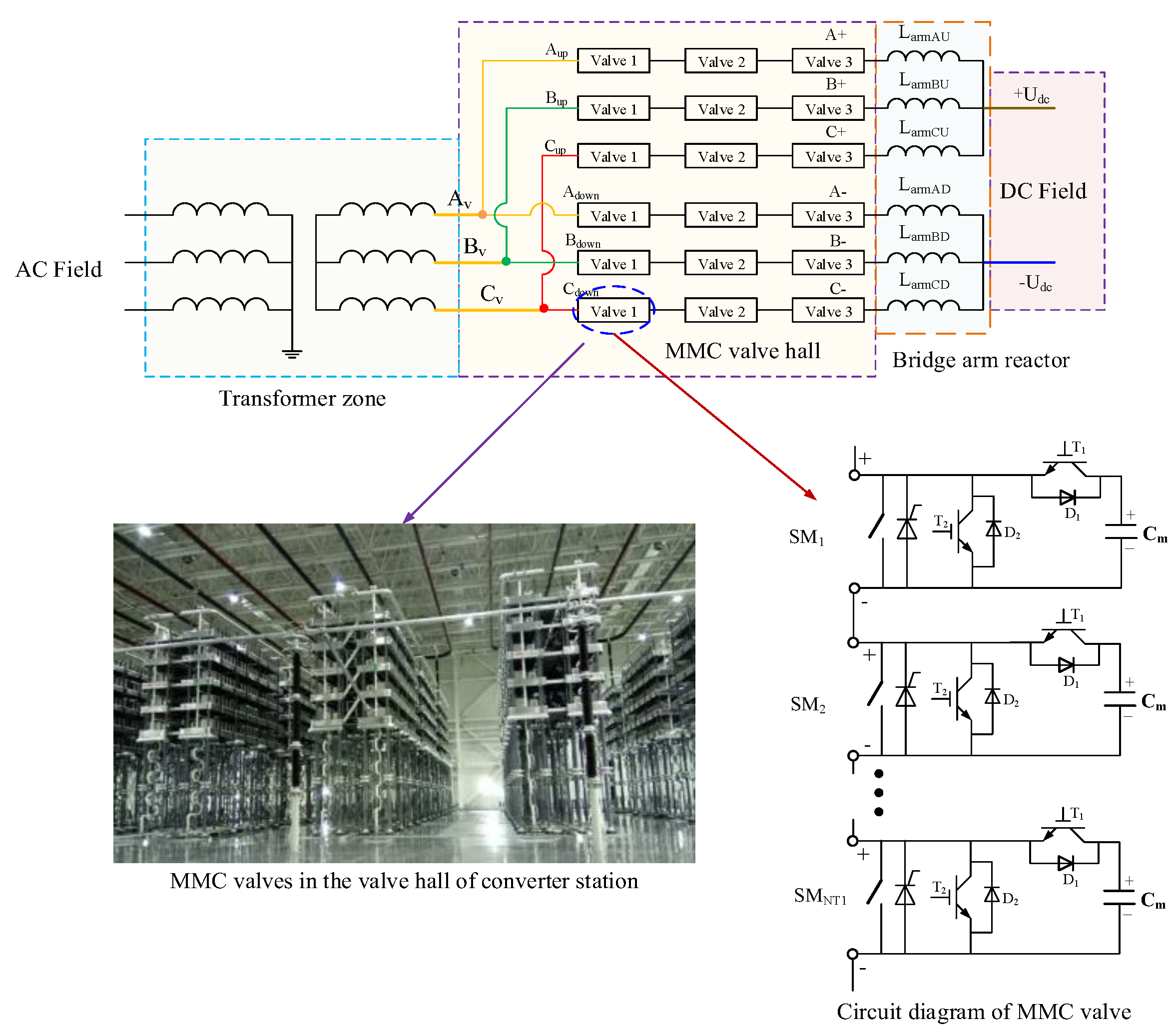
Figure 2.
The conventional electric field analysis process of the MMC valve.
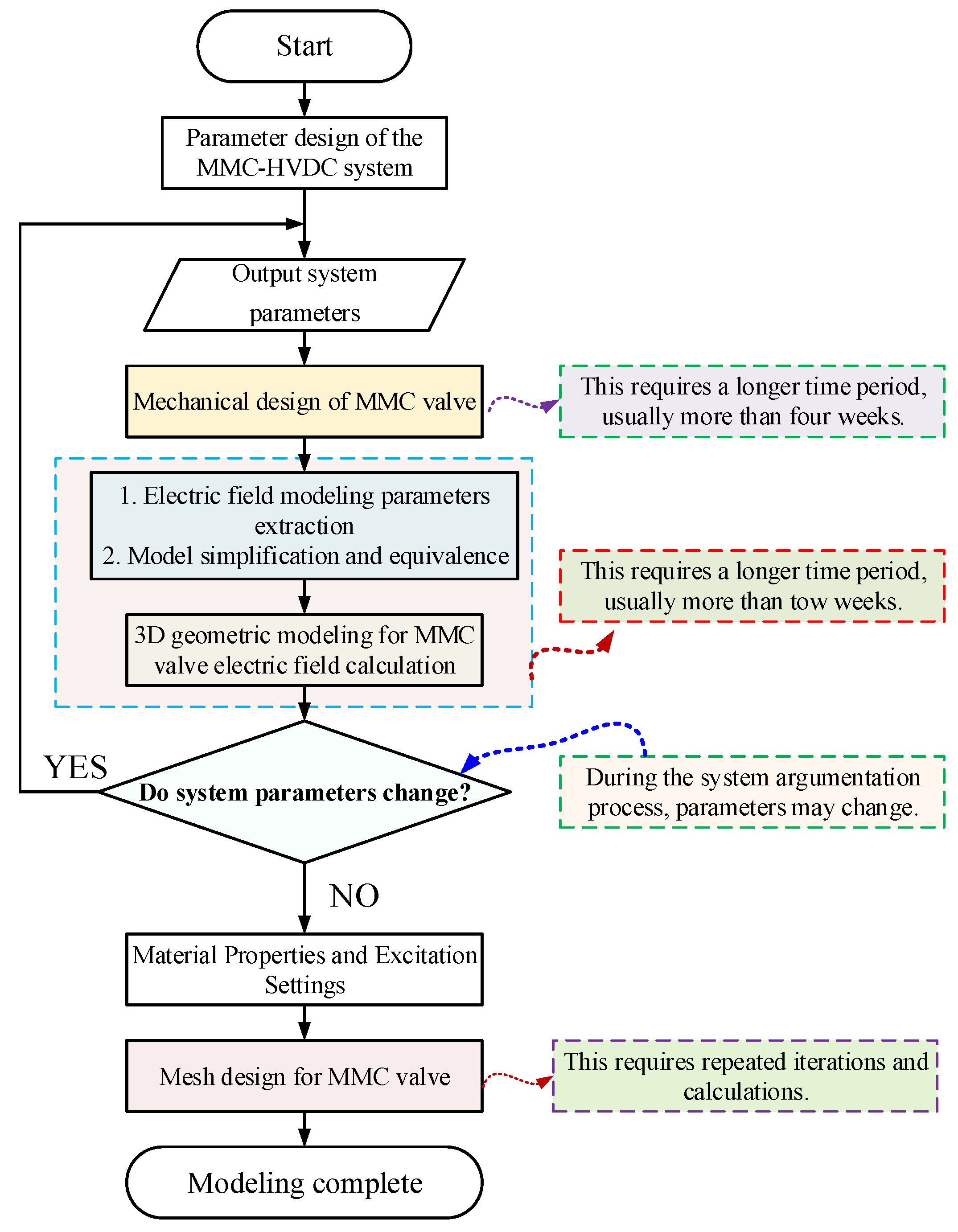
Figure 3.
High-speed modeling process for electric field analysis of the MMC valve.
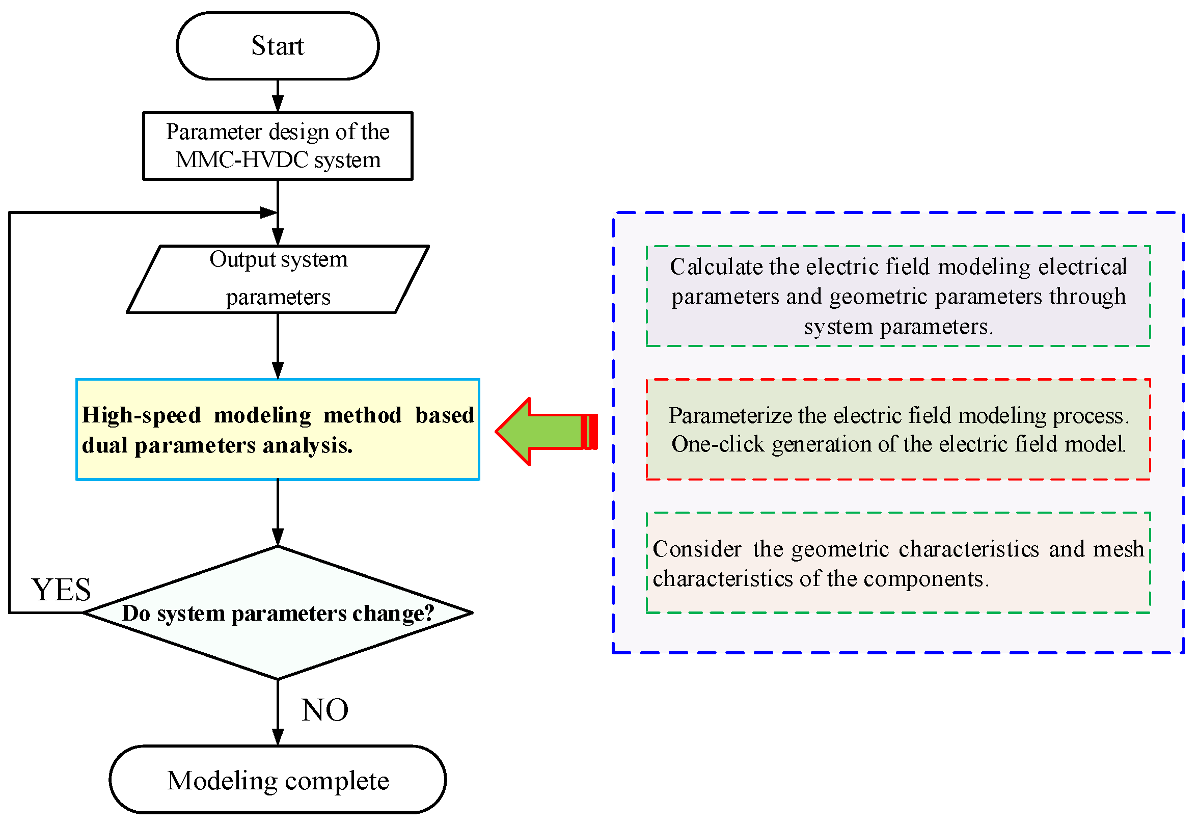
Figure 4.
Electric field equivalence between discrete conductors and a continuous conductor.
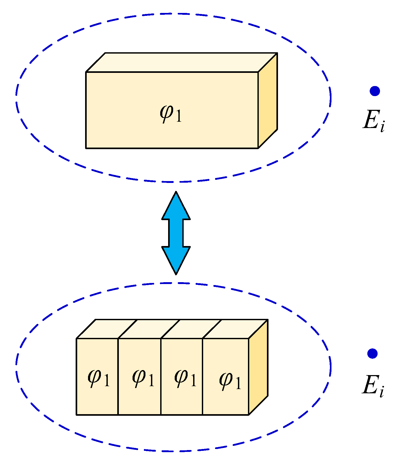
Figure 5.
Model of the submodule, support frame, grading ring, and shielding cover.
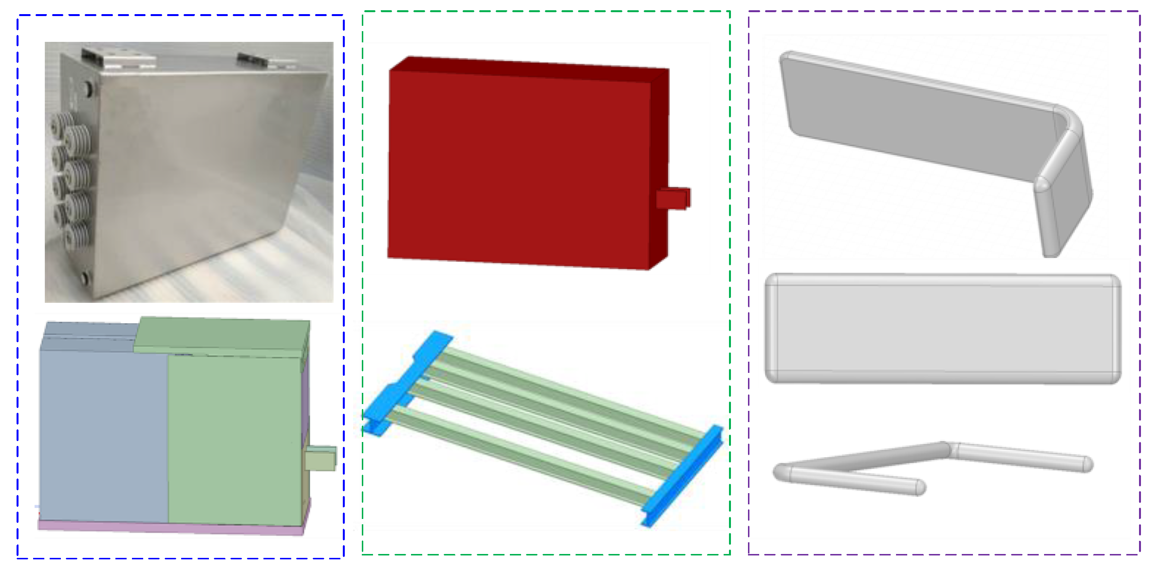
Figure 6.
The process of establishing the electric field model for the MMC valve.
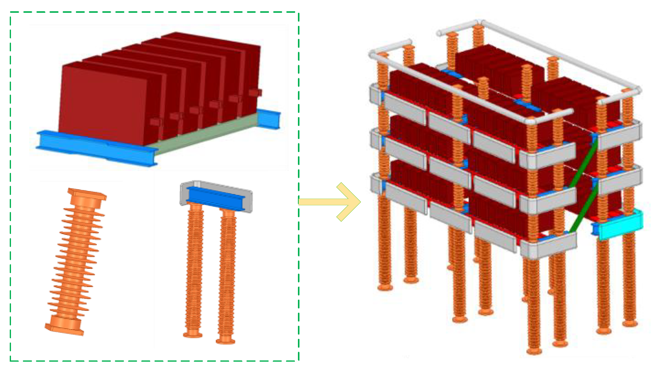
Figure 7.
Discretization modeling and mesh of shielding cover.
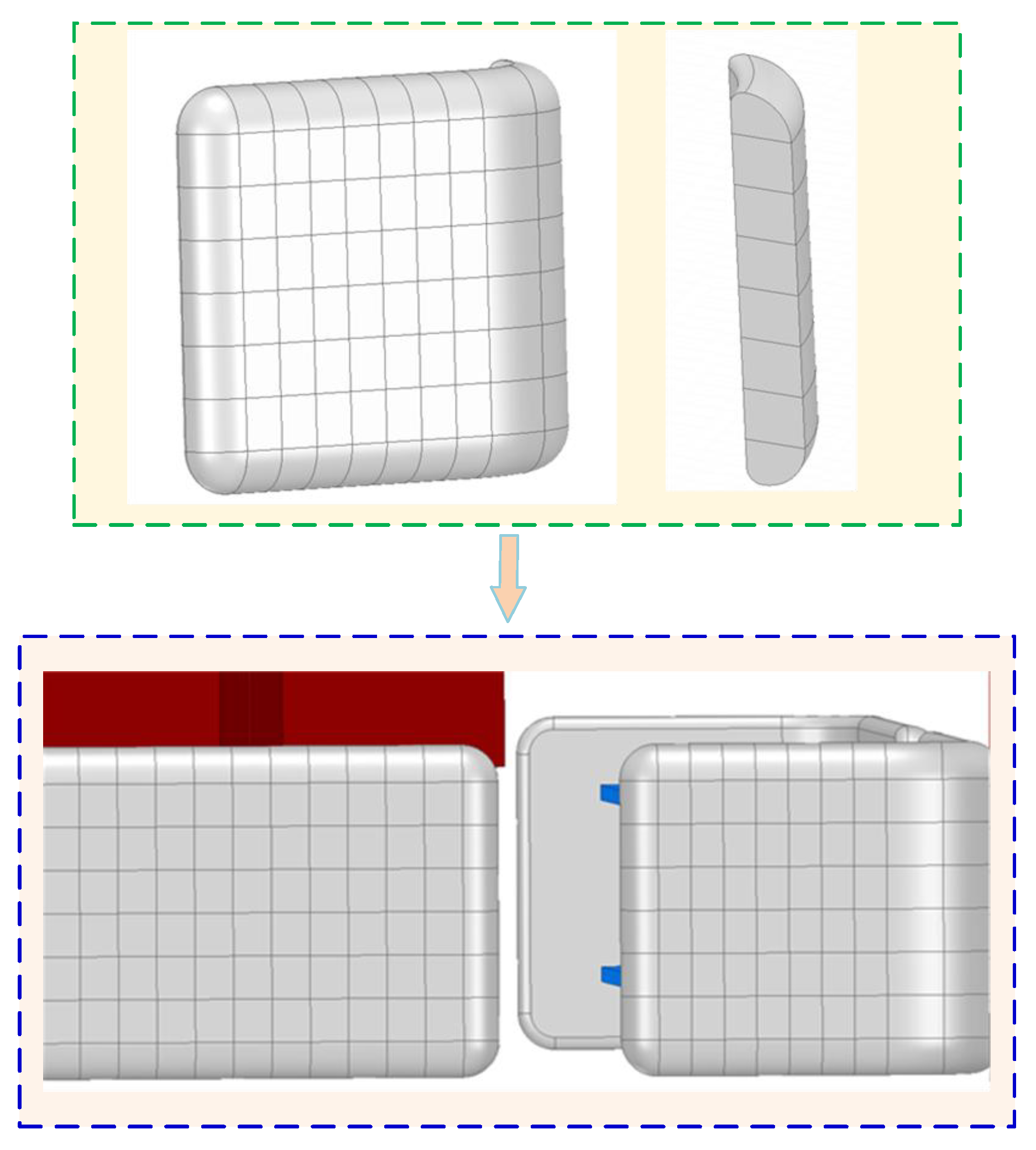
Figure 8.
Initial meshing of conventional modeling (a) and initial meshing of distributed modeling(b).
Figure 8.
Initial meshing of conventional modeling (a) and initial meshing of distributed modeling(b).
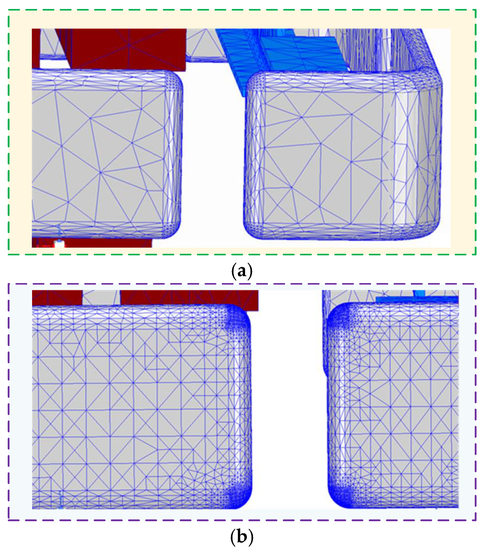
Figure 9.
Curve between error rate, mesh, and calculation time.
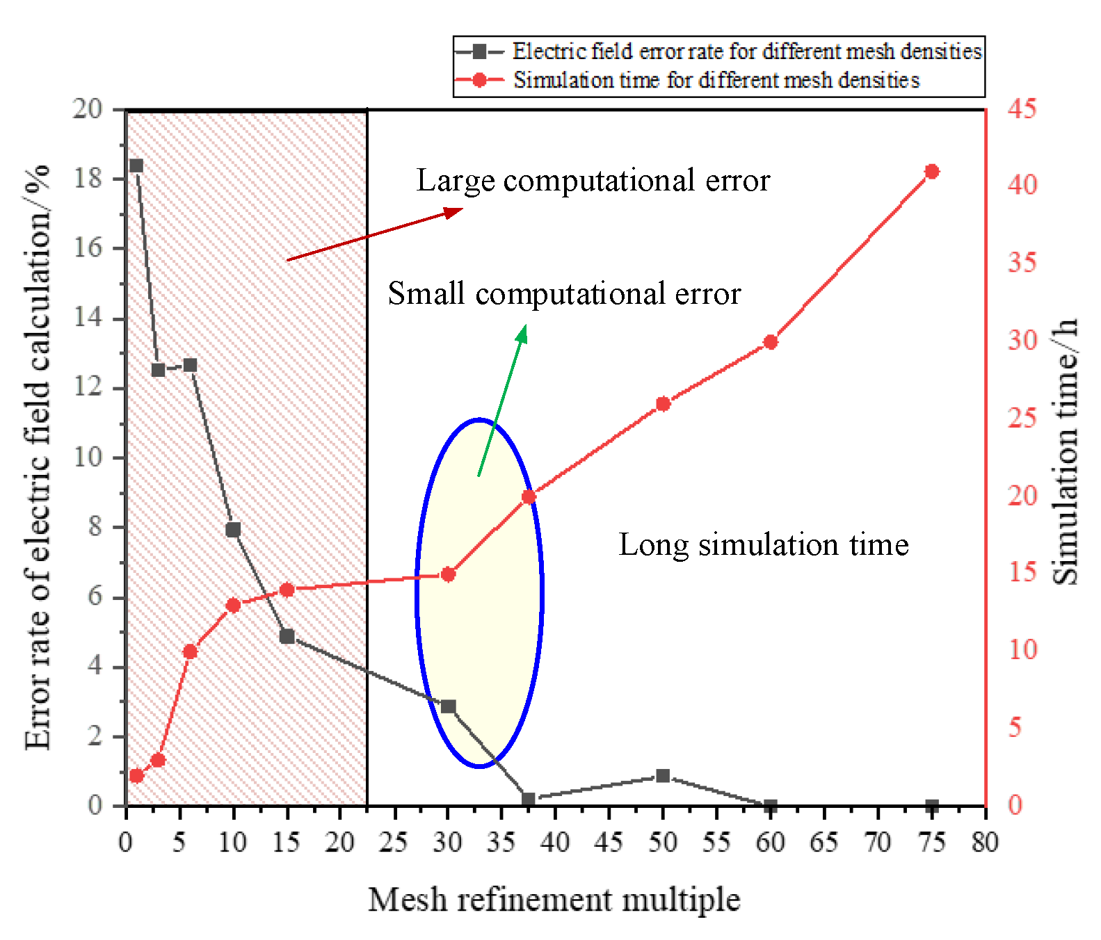
Figure 10.
Electrical field distribution of the MMC valve with convention model (a) and discretization model (b).
Figure 10.
Electrical field distribution of the MMC valve with convention model (a) and discretization model (b).
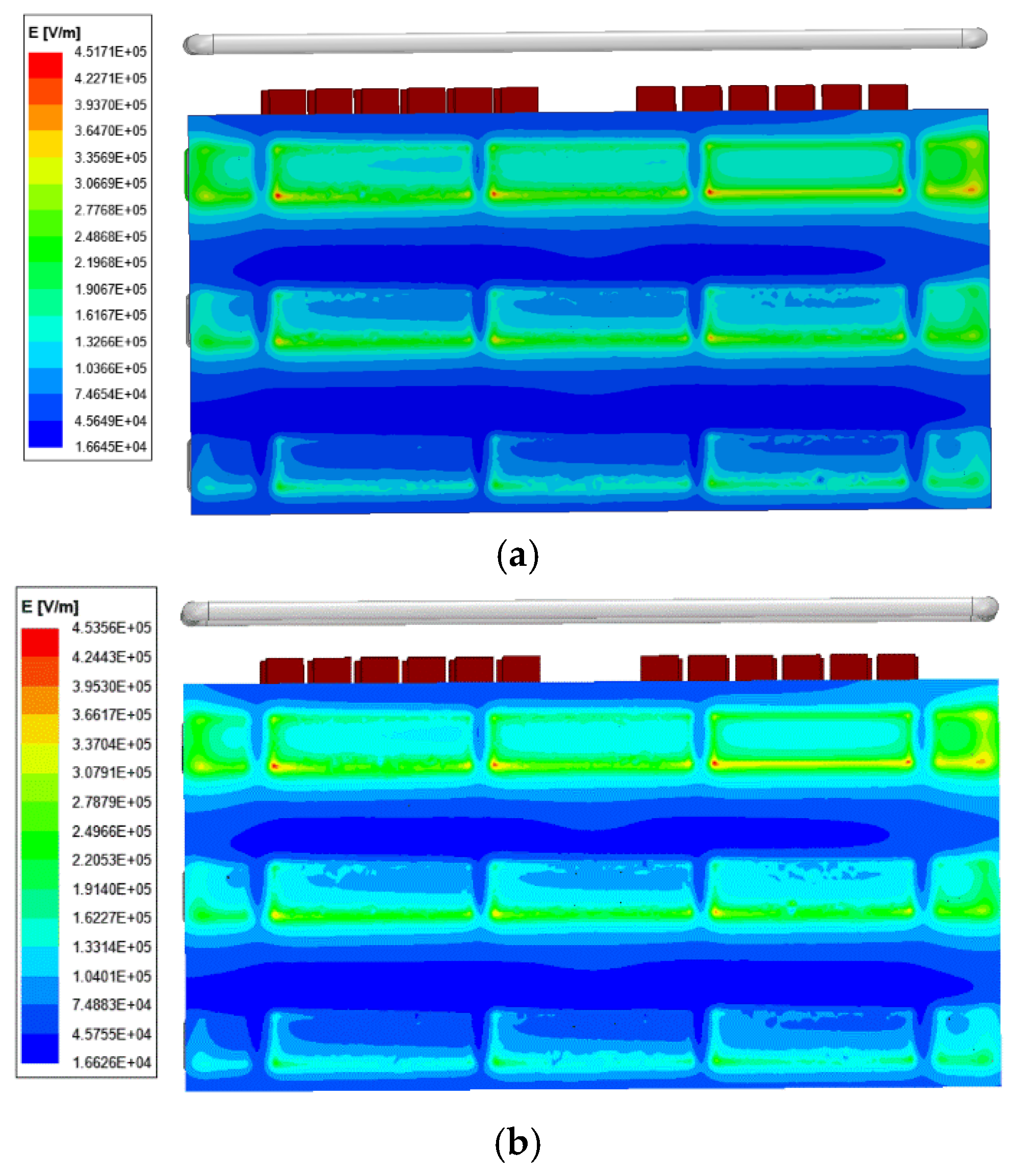

Table 1.
Main parameters of onshore MMC-HVDC system.
| Parameters of system | Value |
|---|---|
| DC voltage Udc | ±320kV |
| DC transmission power Pdc | 1000MW |
| Connection configuration | symmetrical bipolar |
| Sub-module topological | half-bridge |
Table 2.
Parameters calculated by the data-derived system.
| Parameters of MMC valve | Value |
|---|---|
| DC voltage Udc | 1.5625kA |
| Rated voltage of the IGBT | 3.3kV |
| Rated voltage of sub-module | 1.6kV |
| Rated voltage of Capacitor | 2.1kV |
| Capacitance of sub-module | 10mF |
| Rated number of sub-modules per arm | 200 |
| Number of sub-modules per valve | 72 |
Table 3.
Comparison results of the two methods for electric field calculation.
| Modeling methods | Modeling time | Mesh refinement factor | Maximum electric field strength | Error rate /% | Simulation time |
|---|---|---|---|---|---|
| Conventional methods | >120h | 1(initial) | 0.368kV/mm | 18.4 | 2h |
| 6 | 0.3939kV/mm | 12.66 | 10h | ||
| 10 | 0.415kV/mm | 7.95 | 13h | ||
| 15 | 0.429kV/mm | 4.88 | 14h | ||
| 30 | 0.438kV/mm | 2.88 | 15h | ||
| 40 | 0.452kV/mm | 0.22 | 20h | ||
| 50 | 0.455kV/mm | 0.87 | 26h | ||
| 60 | 0.451kV/mm | 0 | 30h | ||
| 75 | 0.451kV/mm | 0 | 41h | ||
| High speed methods | <16h | No operation | 0.453kV/mm | 0.4 | 4h |
Disclaimer/Publisher’s Note: The statements, opinions and data contained in all publications are solely those of the individual author(s) and contributor(s) and not of MDPI and/or the editor(s). MDPI and/or the editor(s) disclaim responsibility for any injury to people or property resulting from any ideas, methods, instructions or products referred to in the content. |
© 2025 by the authors. Licensee MDPI, Basel, Switzerland. This article is an open access article distributed under the terms and conditions of the Creative Commons Attribution (CC BY) license (http://creativecommons.org/licenses/by/4.0/).
Copyright: This open access article is published under a Creative Commons CC BY 4.0 license, which permit the free download, distribution, and reuse, provided that the author and preprint are cited in any reuse.


