
Submitted:
13 March 2025
Posted:
13 March 2025
You are already at the latest version
Abstract
In this paper, we analyze the displacements of a geodetic reference pillar due to thermal loading, which typically occurs when the sunlit side of the pillar heats up more than the shaded side. This temperature differential induces bending of the pillar, resulting in the horizontal displacement of the screw used for forced centering of the instrument. Measuring displacement in the field is challenging, as it is difficult to thermally isolate the displacement sensor mount from the environment, whereas measuring rotations is much easier. Under controlled laboratory conditions, we measured the inclination of the plate with the forced-centering screw and simultaneously recorded the displacements near the top of a test pillar. We found excellent agreement between the displacements calculated from the inclination and the directly measured displacements. Our results demonstrate that using an isolated inclinometer and converting the measured inclination values into displacements provides a representative characterization of the behavior of a pillar for precise geodetic measurements.
Keywords:
geodetic reference pillar
; thermal loading
; bending
; displacements
; rotations
; measurements
1. Introduction
Well-stabilized reference points are essential for precise geodetic measurements of ground movements and structural displacements. These points serve as the basis for measuring control points on or near the observed objects. The stabilization of these points is crucial to enable the often desired or even required accuracy of determining control point displacements within 1 mm. To achieve such high precision, we need to better understand the behavior of the reference points under different conditions.
The reference points are often stabilized by reinforced concrete pillars equipped with bolts for forced centering of the instrument. When properly executed, this stabilization ensures the long-term stability of the reference point throughout the measurement period of the structure or its surroundings. Stabilization with reinforced concrete pillars offers many advantages if carried out correctly. However, in some cases they are not done correctly. A common problem occurs when a plastic pipe, usually of small diameter (sometimes only 20 cm), is inserted into the foundation of the pillar to serve as formwork. Reinforcement is placed inside the pipe, which is then filled with concrete. At the top of the pipe, a steel plate is anchored in the fresh concrete with a forced centering screw. These pipes are available in various colors, including black. (Figure 1).
Relatively small diameters of the cross-sections and the dark, mainly black color of the tube left on the pillar pose a considerable problem when exposed to sunlight. Temperature differences within the pillar can have a considerable influence on the position of the forced centering screw, to such an extent that they cannot be ignored in precise measurements, see [1]. Local temperature variations in the reinforced concrete column, caused by one side being exposed to sunlight while the other is in the shade, lead to an expansion of the sunlit part and consequently to bending of the column. This bending leads to displacements of the forced-centering screw, which cannot be neglected under real conditions. Thermal effects on reinforced concrete columns can cause displacements up to 1 mm [2].
Measuring the displacement of a reference pillar in situ is a challenge, as it is difficult to thermally insulate the displacement sensor mount and the installation of such sensors would require considerable effort. On the other hand, the bending of the pillar also changes the inclination of the steel plate with the forced centering screw. This inclination can be measured directly with a precise thermally insulated inclinometer, which is an interesting alternative and motivation for this study. Note, however, that the measured inclinations are only applicable if a simple correlation to displacements can be established.
In our experimental setup, we performed inclination measurements on a test pillar where we could also measure displacements and temperatures to validate our numerical model. Our study focuses exclusively on the horizontal displacements of the pillar due to thermal loading, as the positional components of displacement are the main focus in 2D geodetic networks (the vertical component is negligible in 2D network analysis).
This topic has already been recognized by the scientific community. In the work of Kopáčik et al. [3] and Lipták [4], the horizontal displacements of geodetic reference points due to thermal loads were considered in the context of monitoring bridge deformations. Gerhatova et al. [5,6] investigated the impact of thermal effects on the positions of GNSS antennas and concluded that the temperature-induced bending of pillar monuments can lead to significant position shifts. Their research emphasizes the importance of continuous monitoring and environmental aspects in maintaining the accuracy of GNSS data. Lehner [7] and Haas et al. [8] investigated how environmental factors, particularly temperature fluctuations and wind, affect the stability of GNSS monuments and emphasized the need for adequate construction and shielding of the pillars to ensure the reliability of measurements. Lidberg and Lilje [9] assessed the stability of monuments within the SWEPOS GNSS network using terrestrial geodetic techniques. Their results indicate that thermal expansion and uneven heating can lead to deformations of the pillars that affect the positions of the GNSS antennas. The study recommends the insulation and temperature stabilization of pillars to minimize such effects.
The importance of high-precision inclination measurements for monitoring in geodetic and structural applications was reported by several authors. Erol [10] evaluates digital inclinometers for continuous deformation monitoring, showing their effectiveness in tracking structural tilts. Kümpel and Fabian [11] highlight inclination monitoring as essential for assessing the stability of geodetic reference points in permafrost, where ground movements can affect measurement accuracy. Mentes and Bányai [12] and Mentes [13] demonstrate the role of inclination sensors in detecting landslide-induced angular changes, linking them to environmental factors. Glot et al. [14] further confirm the long-term applicability of inclinometers by monitoring the headframe of a salt mine shaft, demonstrating their reliability in detecting slow structural deformations over extended periods. Together, these works stress the need for precise inclination control to ensure reliable geodetic and structural assessments.
Despite that the thermal effects from solar radiation are well known it was only recently that more effort has been dedicated in predicting these effects, focusing on bending deformations, thermal stresses, and structural integrity under moderate temperature changes and relatively large temperature gradients between heated and shaded surfaces. Several studies (e.g., Hagedorn et al. [15], Abid et al. [16], Wang et al. [17], Lu et al. [18], Fan et al. [19], Saad et al. [20]) analyses temperature distributions in concrete elements, particularly in box girders and slabs. Extreme solar heating can increase internal stresses, which, when combined with mechanical loads, can accelerate fatigue and material degradation, see Newell and Goggins [21], He et al. [22]. To predict the varying thermal conditions in a concrete structure numerical models were used by Larsson and Thelandersson [23], Li et al. [24], Zhang et al. [25].
We will here focus on the relationship between the horizontal displacements and the cross-sectional rotations measured as inclinations of a typical pillar used for stabilizing the reference points. The paper presents the experimental setting in controlled laboratory conditions where we were simulating natural solar radiation by heating only one side of the column leaving the other much colder. Through precise measurements, we captured the displacements near the top of the pillar, the inclination of the horizontal plate at the top, and the inclination of the angle bracket near the top, along with the time history of temperatures at several points of the observed structure. This study provides valuable insights into the behavior of reinforced concrete pillars under moderate but non-negligible thermal loads, improving our understanding of their structural response to realistic environmental conditions.
2. Experimental Setting and Computational Model
The behavior of a typical pillar used for forced centering of geodetic instruments was experimentally analyzed under controlled laboratory conditions (see Figure 2). The pillar was made of reinforced concrete and rigidly fixed into a solid concrete block. The concrete was placed using a plastic tube with an inner diameter of 0.217 m, an outer diameter of 0.250 m, and a height of 1.510 m. A standard pre-prepared dry mix of class C25/30 was used for the concrete. Four vertical steel bars, each with a diameter of 12 mm, were installed before pouring. The plastic tube was latter removed to allow for the installation of temperature sensors on the pillar's surface.
Thermal loading was applied using several heaters mounted on a vertical bar on one side of the pillar, while the opposite, cooler side was partially insulated (Figure 2a). This insulation prevented the back side of the pillar from heating due to radiation, allowing it to warm up solely through internal heat transfer. Additionally, it reduced temperature effects on the measuring equipment. Studies, such as [26], examine the effect of temperature on inclinometers. In our research, we were aware of this influence, so we thermally insulated the inclinometers. As a result, the heating of the column had only a minimal impact on their operation.
Several temperature sensors were installed on both the front, heated side of the pillar (Figure 2a) and the back, cooler side (Figure 2b), with measurements recorded every 30 seconds. The installed sensors enabled preliminary studies that led to an optimized vertical arrangement of the heaters, ensuring a nearly uniform temperature distribution along the height of the pillar. This distribution was not only simple but also aligned with the numerical model presented later, making it crucial for establishing a robust relationship between rotations and displacements.
A displacement sensor mount was installed behind the pillar, measuring displacement at the top to capture its actual movement due to thermal loading (Figure 2c). Measurements were taken every 30 seconds, and heating was stopped once the top sensor registered a displacement of 1 mm. Two inclinometers were mounted on the pillar (Figure 2c). The first (Leica Geosystems Nivel 210 – top inclinometer) was placed at the very top of the pillar on an extruded polystyrene (XPS) insulation board to prevent direct heat transfer from the pillar to the inclinometer. The second (Leica Geosystems Nivel 210 – side inclinometer) was mounted laterally on a right-angle bracket attached to the pillar. Measurements were taken every 30 seconds.
A more detailed positioning of the sensors, including dimensions and distances, is shown in Figure 3. Rotations and displacements strongly depend on the vertical position relative to the column. Since the mounting plate is placed at the top, the displacement sensor and inclinometers are positioned nearby. However, due to geometrical constraints, they cannot measure the exact same point. The key geometrical data are as follows: height of the pillar: m; position of the top inclinometer: m; position of the side inclinometer m; position of displacement sensor m.
Based on the experimental setting we now present the model. Given the relatively small dimensions of the cross-section, it is reasonable to assume a linear temperature distribution over the volume. This can be expressed as: . Here, represents the average incremental temperature along the reference axis, while denotes the temperature gradient of a cross-section at position , where is the arc-length parameter along the centroidal axis of the pillar. In our model, the cross-sectional temperature gradients are estimated by subtracting the measured temperatures on the cooler (non-heated) side from those on the heated side at several discrete points along the height of the pillar.
Temperature gradients measured by sensors at three distinct heights are depicted in Figure 4. The sensor positions are: bottom, m, middle, m, and top, m. The gradients were estimated as
where and represent the temperatures on the cooler and heated sides, respectively, at position , and denotes the diameter of the pillar. For the present study we have m. From Figure 4 we can see that the temperature gradients are almost evenly distributed over the height. This was achieved by carefully planning the experiment to realistically model the effect of solar radiation on such structures. The results allow us to assume a constant with respect to , while its temporal distribution in our experiment can be seen in Figure 4.
The relationship between lateral displacements and thermal loads in beam-like structures, in the special case where no mechanical loads are present, is governed by a simple ordinary differential equation:
Integrating once gives the slope:
and integrating again results in the lateral deflection:
Here denotes the lateral deflections of a reference axis, and is the temperature coefficient of the concrete forming the pillar. The integration constants are determined from the boundary conditions at the clamped end, leading to . Note that the locations of measured displacements and rotations generally do not coincide. However, for a constant cross-sectional temperature gradient, const, a simple relationship between displacements and rotations can be derived:
which leads to
For such a simple temperature distribution, uniform along the height, the coefficient relating displacement and rotation is independent of temperature. This allows for straightforward transformations between these quantities, regardless of the measurement locations.
In the present experiment, displacements were measured atm, while inclinometers were positioned at m and m. This yields the coefficients used for postprocessing the measured data
for the rotations at the top and
for the side measurements.
3. Experimental Results
We first present the measured displacements up to the top of the pillar, see Figure 5. It is obvious that the temporal course of the displacements is closely linked to the temperature gradients shown in Figure 4. In both the heating and cooling phases, a total of 10 hours of time history is shown with almost negligible displacements at the end of the observations.
Figure 6 shows the rotations at two positions where the inclinometers were attached. The upper one was mounted on the 3 cm thick insulating layer at the top of the pillar, while the lateral one was mounted on the cantilever near the top on the cooler (unheated) side of the pillar.
During the heating phase, the temperature of inclinometer placed at the top of the pillar increased by 2.9 K, while that of inclinometer attached on the angle bracket at side rose by 2.0 K as shown in Figure 7. It is evident that the top inclinometer experienced greater slightly heating than the side one, despite being placed on an insulation board made of extruded polystyrene. We need to stress also that the side inclinometer was firmly fixed while the top one was only put on the insolation layer above the top plate.
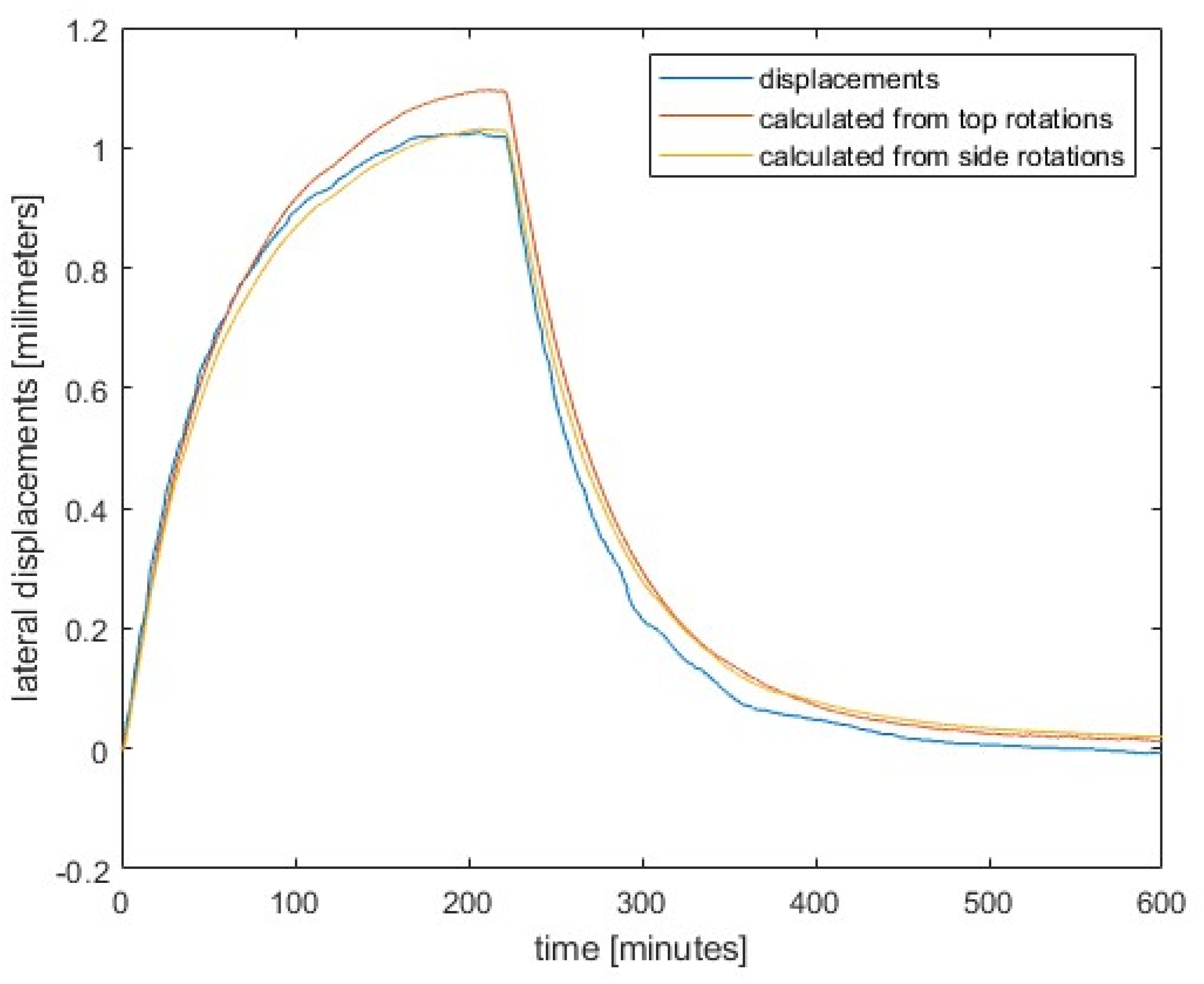
Figure 8 shows the comparison between the measured displacements and those obtained from the measured rotations. The transformation coefficients and as explained in the previous section were used. The results show excellent agreement, which illustrates the suitability of measuring rotations instead of displacements, which is a much simpler and more convenient technique. We must emphasize that the results of the inclinometer attached to the side near the top obviously agree better. We attribute this to the better insulation and mounting of this inclinometer.
4. Conclusions
Prior to the construction of large infrastructure projects (such as tunnels and viaducts), a network of geodetic points must be established. These points are used throughout the construction process and afterwards for all geodetic measurements. They are usually stabilized with pillars, which should remain fixed during and after construction. In practice, however, many pillars have proven to be insufficiently stabilized as they have too small a cross-section and are encased in black-colored pipes. When exposed to sunlight, the sunlit side of these pillars heats up much more than the shaded side, which leads to thermal stresses and consequently to the pillar bending. The displacement of the forced centering screw for the instrument can therefore be considerable.
Measuring the displacement of a column caused by thermal stress in the field is almost impossible, as isolating the displacement sensor mount from external influences is a major challenge. However, it is much easier to isolate an inclinometer mounted on the column, which measures the inclination of the plate that holds the screw for forced centering. From the measured inclination, the thermally induced displacement can be calculated without much effort.
In the laboratory, we heated a test column from one side and measured the temperatures on the hot and cold sides, the inclinations at the top of the column and on the side, as well as the displacements. Using the equations presented, we calculated the displacements from the measured angles and adjusted them to the level of the displacement sensor so that the calculated displacements were directly comparable. The displacement curves derived from the inclination measurements agree very well with the directly measured displacements over time.
Thus, this paper presents a reliable indirect method for determining the displacement of geodetic measurement pillars due to thermal loading, a common problem caused by inadequate pier design.
Author Contributions
This work was achieved in collaboration among all authors. Conceptualization—R.M., A.P. and T.A.; Formal analysis—R.M. and D.Z.; Investigation—R.M.; methodology—R.M., T.A. and A.P.; Project administration—A.P.; Supervision—D.Z.; Visualization—R.M. and T.A.; Writing, original draft—R.M., A.P., D.Z. and T.A. All authors have read and agreed to the published version of the manuscript.
Funding
The research was financially supported by the Slovenian Research and Innovation Agency (ARIS) through research core funding No. P2-0227 Geoinformation Infrastructure and Sustainable Spatial Development of Slovenia, No. P2-0260 Structural Mechanics and No. P2-0268 Geotechnology.
Data Availability Statement
The original contributions presented in this study are included in the article/supplementary material. Further inquiries can be directed to the corresponding author(s).
Acknowledgments
The authors would like to express their gratitude to Mitja Kozamernik and Gregor Trtnik from Igmat d.d., Slovenian Building Materials Institute, for conducting the measurements on the test column.
Conflicts of Interest
The authors declare no conflicts of interest.
References
- Močnik, R.; Koler, B.; Zupan, D.; Ambrožič, T. The Influence of Pillar Displacements on Geodetic Measurements. Appl. Sci. 2020, 10, 8319. [CrossRef]
- Močnik, R.; Koler, B.; Zupan, D.; Ambrožič, T. Investigation of the Precision in Geodetic Reference-Point Positioning Because of Temperature-Induced Pillar Deflections. Sensors 2019, 19, 3489. [CrossRef]
- Kopáčik, A.; Kyrinovič, P.; Lipták, I.; Erdély, J. Automated Monitoring of the Danube Bridge Apollo in Bratislava. In Proceedings of the FIG Working Week 2011, Marrakech, Morocco, 18–22 May 2011; pp. 1–11. Available online: https://www.fig.net/resources/proceedings/fig_proceedings/fig2011/papers/ts01e/ts01e_kopacik_kyrinovic_et_al_4845.pdf (accessed on 29 December 2024).
- Lipták, I. Analysis of Bridge Structure Deformation Measured by Total Station. In Proceedings of the 5th International Conference on Engineering Surveying, Brijuni, Croatia, 22–24 September 2011; pp. 99–104.
- Gerhatova, L., Hefty, J., Papco, J., Minarikova, M. Displacements of GNSS Antenna Position due to Thermal Bending of Pillar Monument. In Report on the Symposium of the IAG Subcommission for Europe (EUREF), Leipzig, Germany, 3-5 June 2015. Available online: https://www.euref.eu/sites/default/files/symposia/2015Leipzig/p-03-02-Gerhatova.pdf (accessed on 29 December 2024).
- Gerhatova, L., Hefty, J., Spanik, P. Short-Term and Long-Term Variability of Antenna Position Due to Thermal Bending of Pillar Monument at Permanent GNSS Station. Reports on Geodesy and Geoinformatics 2016, 100, 67-77. [CrossRef]
- Lehner, W.M. Evaluation of Environmental Stresses on GNSS-Monuments. Master’s Thesis, Chalmers University of Technology, Goteborg, Sweden, 2011. Available online: https://publications.lib.chalmers.se/records/fulltext/165054.pdf (accessed on 29 December 2024).
- Haas, R.; Bergstrand, S.; Lehner, W. Evaluation of GNSS Monument Stability. In Reference Frames for Applications in Geosciences, International Association of Geodesy Symposia; Altamimi, Z.; Collilieux, X., Eds.; Springer: Berlin/Heidelberg, Germany, 2013; Volume 138, pp. 45–50. [CrossRef]
- Lidberg, M.; Lilje, M. Evaluation of Monument Stability in the SWEPOS GNSS Network Using Terrestrial Geodetic Methods-up to 2003. In Reports in Geodesy and Geographical Information Systems, LMV-Rapport 2007: 10; Lantmäteriet: Gävle, Sweden, 2007. Available online: https://www.lantmateriet.se/contentassets/4a728c7e9f0145569edd5eb81fececa7/lmv-rapport_2007_10.pdf (accessed on 29 December 2024).
- Erol, B. Evaluation of High-Precision Sensors in Structural Monitoring. Sensors 2010, 10, 10803-10827. [CrossRef]
- Kümpel, H.J.; Fabian, M. Tilt monitoring to assess the stability of geodetic reference points in permafrost environment. Physics and Chemistry of the Earth, Parts A/B/C 2003, 28, 1249-1256. [CrossRef]
- Mentes, G.; Bányai, L. Observation of Landslide Movements by Geodetic and Borehole Tilt Measurements. In INGEO 2014 – 6th International Conference on Engineering Surveying, Prague, Czech republic, 3-4 April 2014; pp. 53-58. Available online: https://www.fig.net/resources/proceedings/2014/2014_ingeo/TS2-04_Mentes.pdf.pdf (accessed on 4 March 2025).
- Mentes, G. Investigation of Dynamic and Kinematic Landslide Processes by Borehole Tiltmeters and Extensometers. Procedia Earth and Planetary Science 2015, 15, 421-427. [CrossRef]
- Glot, I.; Shardakov, I., Shestakov, A.; Tsvetkov R.; Gusev, G. Inclinometer-Based Long-Term Monitoring of the Headframe of Salt Mine Shaft. J. Phys. Conf. Ser. 2021, 1945, 012009, 1-6. Available online: https://iopscience.iop.org/article/10.1088/1742-6596/1945/1/012009/pdf (accessed on 4 March 2025).
- Hagedorn, R.; Martí-Vargas, J.R.; Dang, C.N.; Micah Hale, W.; Floyd, R.W. Temperature gradients in bridge concrete I-girders under heat wave. J. Bridge Eng. 2019, 24(8), 04019077. [CrossRef]
- Abid, S.R.; Tayşi, N.; Özakça, M. Temperature Records in Concrete Box-Girder Segment Subjected to Solar Radiation and Air Temperature Changes. In IOP Conference Series: Materials Science and Engineering, 870, Assiut, Egypt, 11-12 February 2020; pp. 1-16. Available online: https://iopscience.iop.org/article/10.1088/1757-899X/870/1/012074 (accessed on 11 March 2025).
- Wang, Z.W.; Zhang, W.M.; Tian, G.M.; Liu, Z. Joint values determination of wind and temperature actions on long-span bridges: Copula-based analysis using long-term meteorological data. Eng. Struct. 2020, 219, 110866. [CrossRef]
- Lu, Y.; Li, D.; Wang, K.; Jia, S. Study on solar radiation and the extreme thermal effect on concrete box girder bridges. Appl. Sci. 2021, 11(14), 6332. [CrossRef]
- Fan, J.S.; Liu, Y.F.; Liu, C. Experiment study and refined modeling of temperature field of steel-concrete composite beam bridges. Eng. Struct. 2021, 240, 112350. [CrossRef]
- Saad, S.; Nasir, A.; Bashir, R.; Pantazopoulou, S. Effect of Climate Change on Thermal Loads in Concrete Box Girders. Journal of Bridge Engineering 2025, 30(3). [CrossRef]
- Newell, S.; Goggins, J. Investigation of Thermal Behaviour of a Hybrid Precasted Concrete Floor using Embedded Sensors. Int. J. Concr. Struct. Mater. 2018, 12, 66. [CrossRef]
- He, S.; Cao, J.; Chai, J.; Yang, Y.; Li, M.; Qin, Y.; Xu Z. Effect of temperature gradients on the microstructural characteristics and mechanical properties of concrete. Cement and Concrete Research 2024, 184, 107608. [CrossRef]
- Larsson, O.; Thelandersson, S. Estimating extreme values of thermal gradients in concrete structures. Mater. Struct. 2011, 44. [CrossRef]
- Li, Y.; Huang, X.; Zhu J. Research on temperature effect on reinforced concrete bridge pylon during strong cooling weather event. Eng. Struct. 2022, 273, 115061. [CrossRef]
- Zhang, K.; Lei, J.; Wang, Z.; Yuan, Q. A numerical algorithm for damage progression of reinforced concrete bridge piers during air temperature and solar radiation cycles. Eng. Struct. 2024, 319, 118876. [CrossRef]
- Li, J.; Zhu, S.; Ji, W.; Li, G.Q.; Wang, Y.; Qi, H. Development of High-Temperature Resistant Inclinometers for Structural Displacement Acquisition of the Buildings Subjected to Fire. Fire Technol. 2024, 1-30. [CrossRef]
Figure 1.
Examples of reference points for precise geodetic measurements: (a) First example; (b) Second example; (c) Third example; (d) Fourth example.
Figure 1.
Examples of reference points for precise geodetic measurements: (a) First example; (b) Second example; (c) Third example; (d) Fourth example.
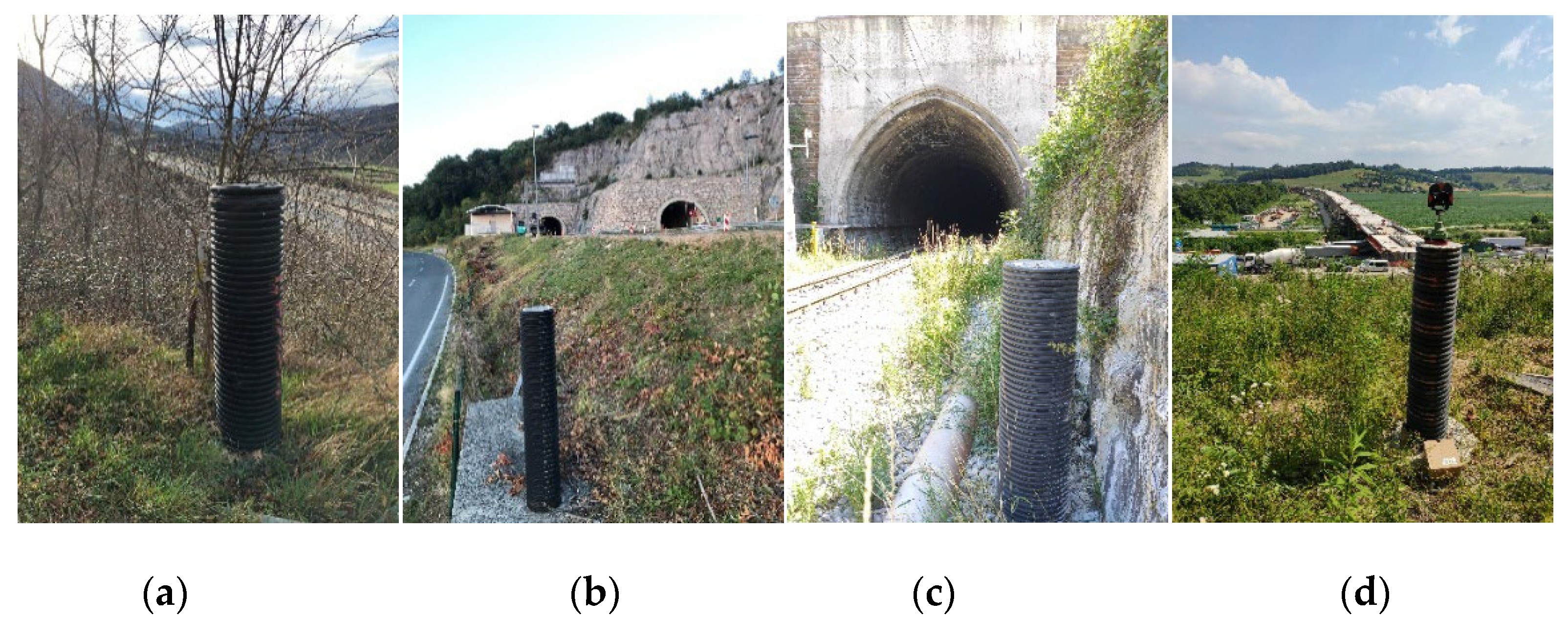
Figure 2.
Experimental setting: (a) Heated side of the pillar; (b) Cooler side of the pillar; (c) Displacement sensor and two inclinometers.
Figure 2.
Experimental setting: (a) Heated side of the pillar; (b) Cooler side of the pillar; (c) Displacement sensor and two inclinometers.
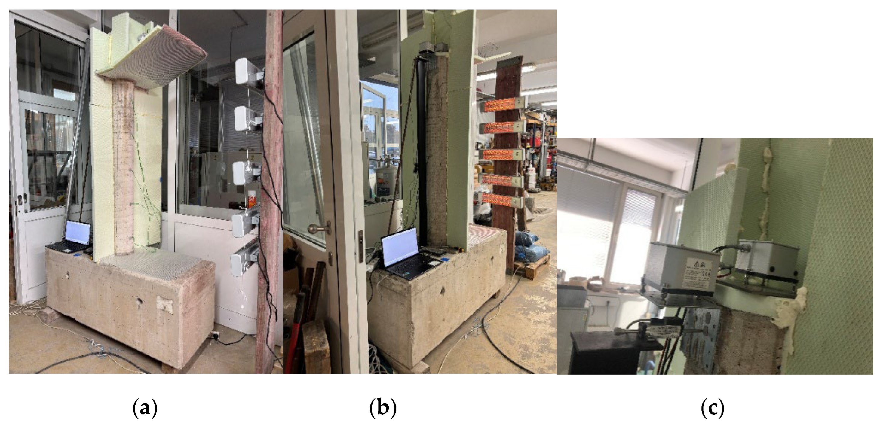
Figure 3.
Details and geometrical data of the setting: (a) More detailed positioning; (b) Dimensions and distances.
Figure 3.
Details and geometrical data of the setting: (a) More detailed positioning; (b) Dimensions and distances.
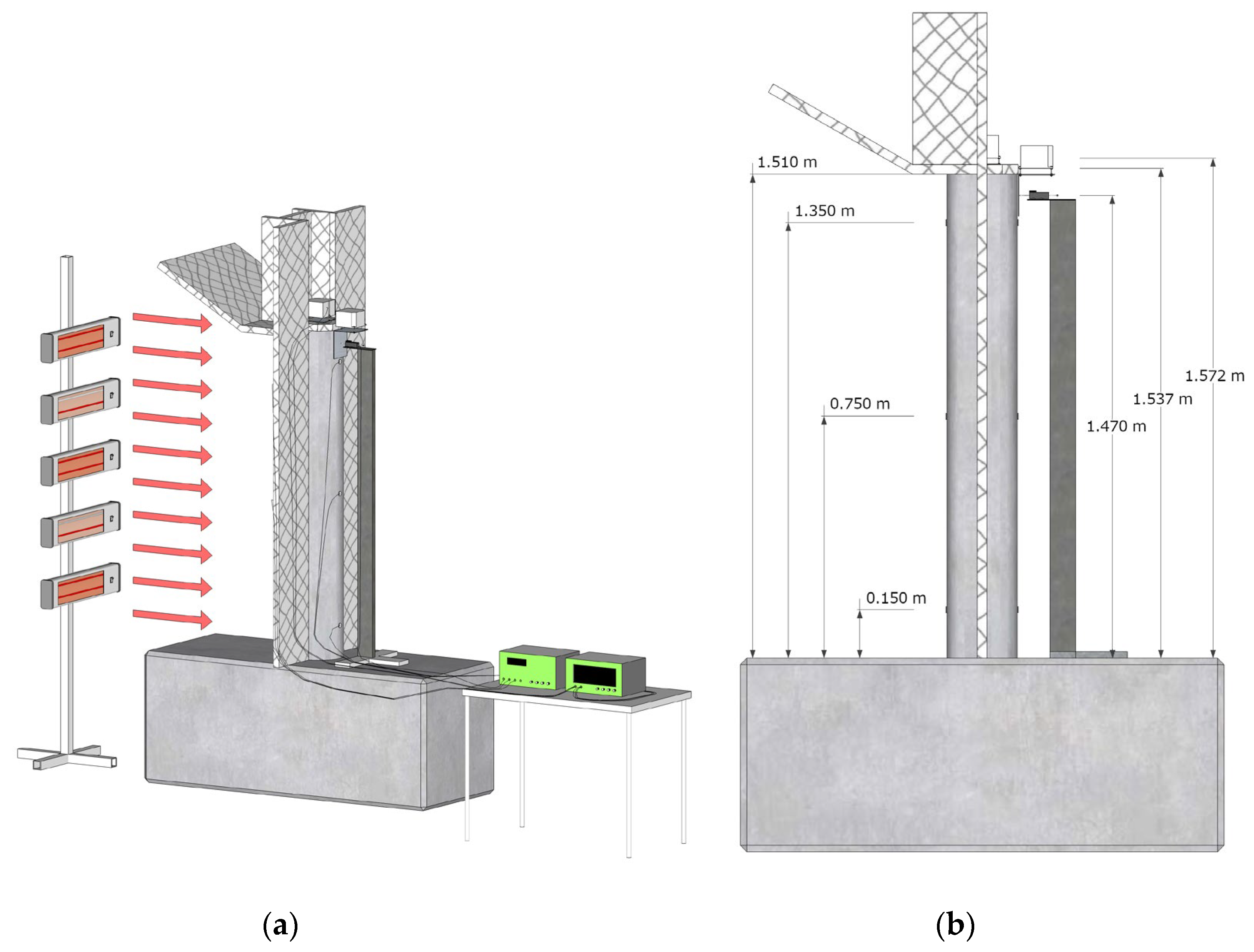
Figure 4.
Temperature gradients at three different heights of the pillar.
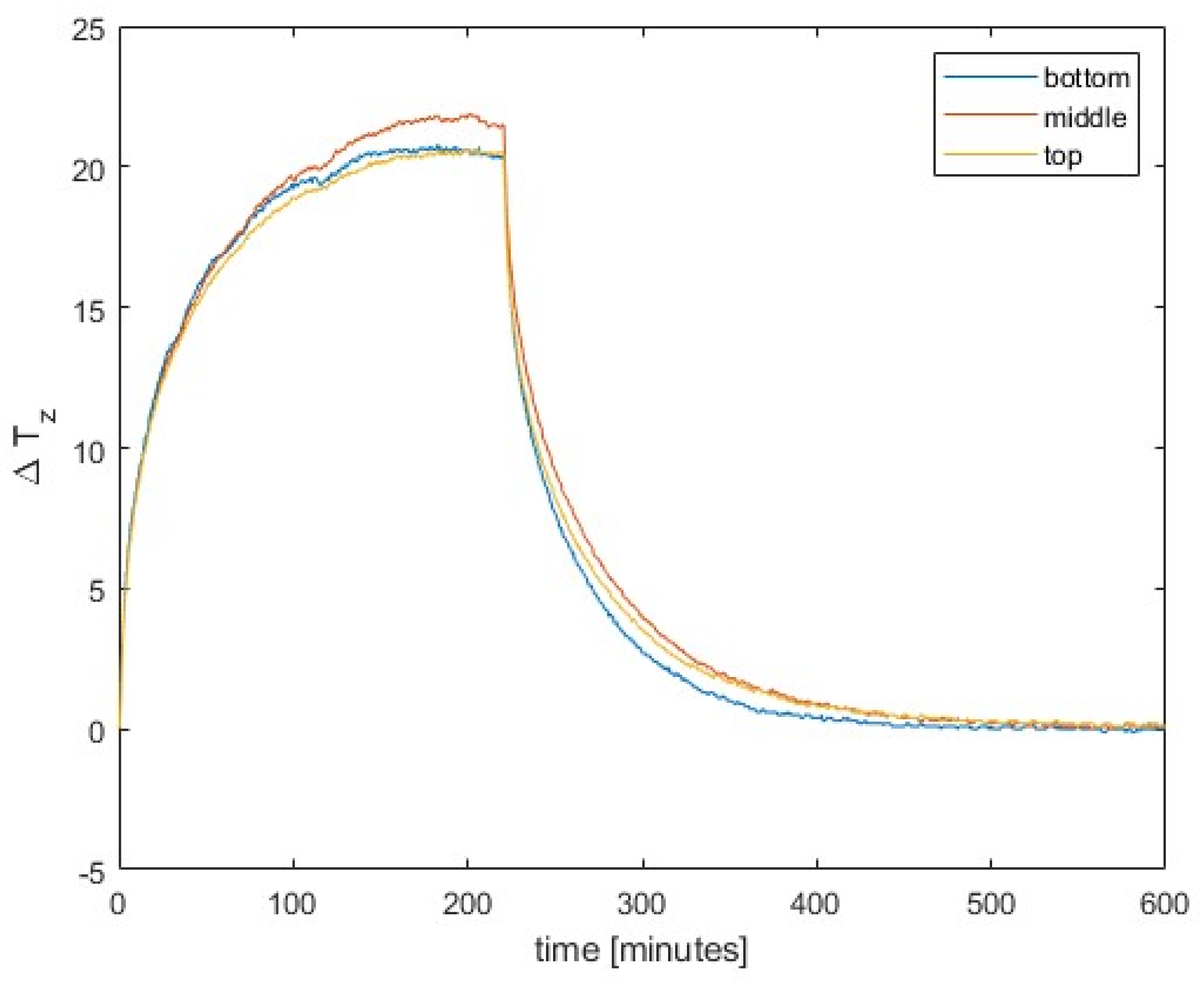
Figure 5.
Lateral displacements at the top.
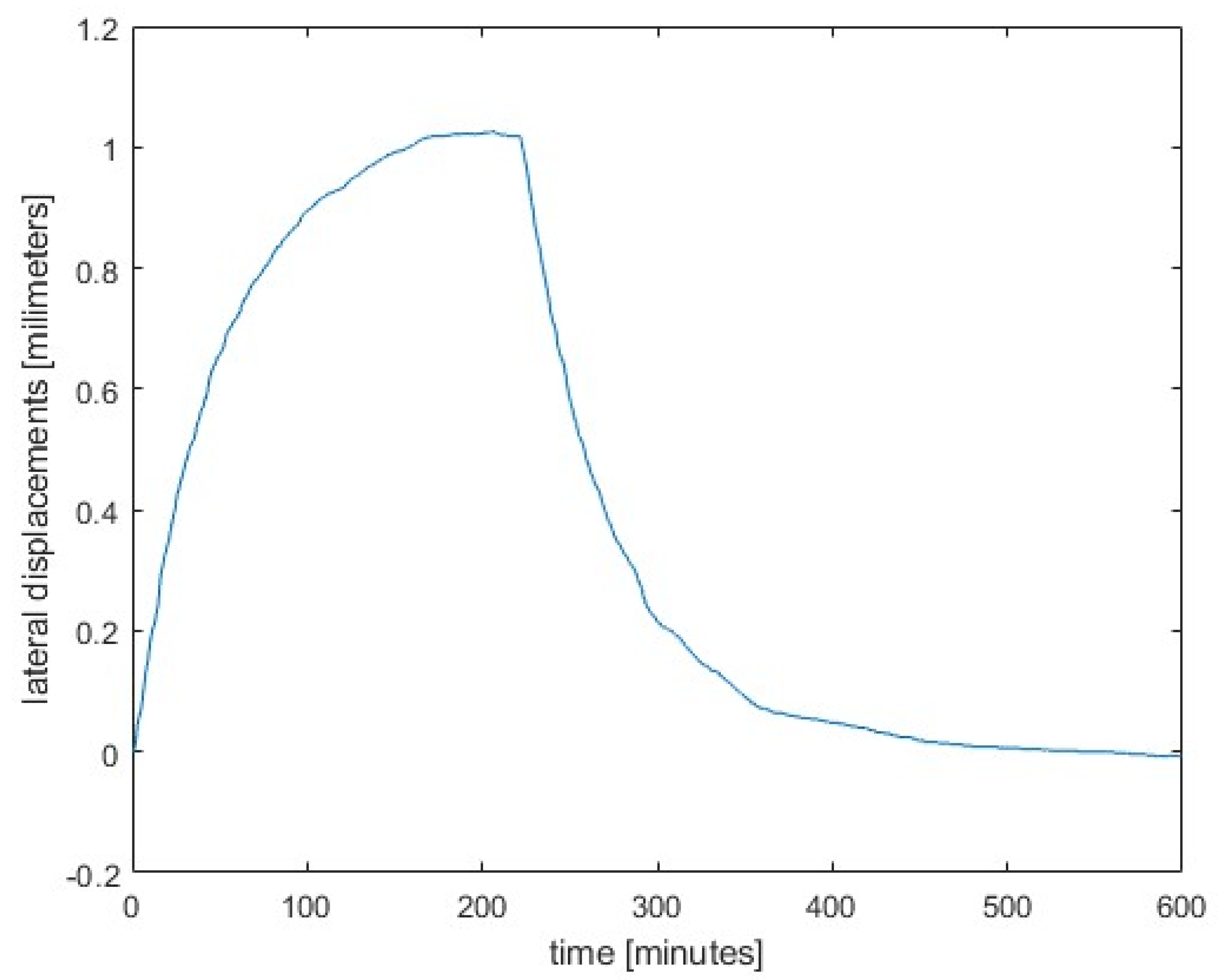
Figure 6.
Absolute values of relative rotations at two positions at and near the top.
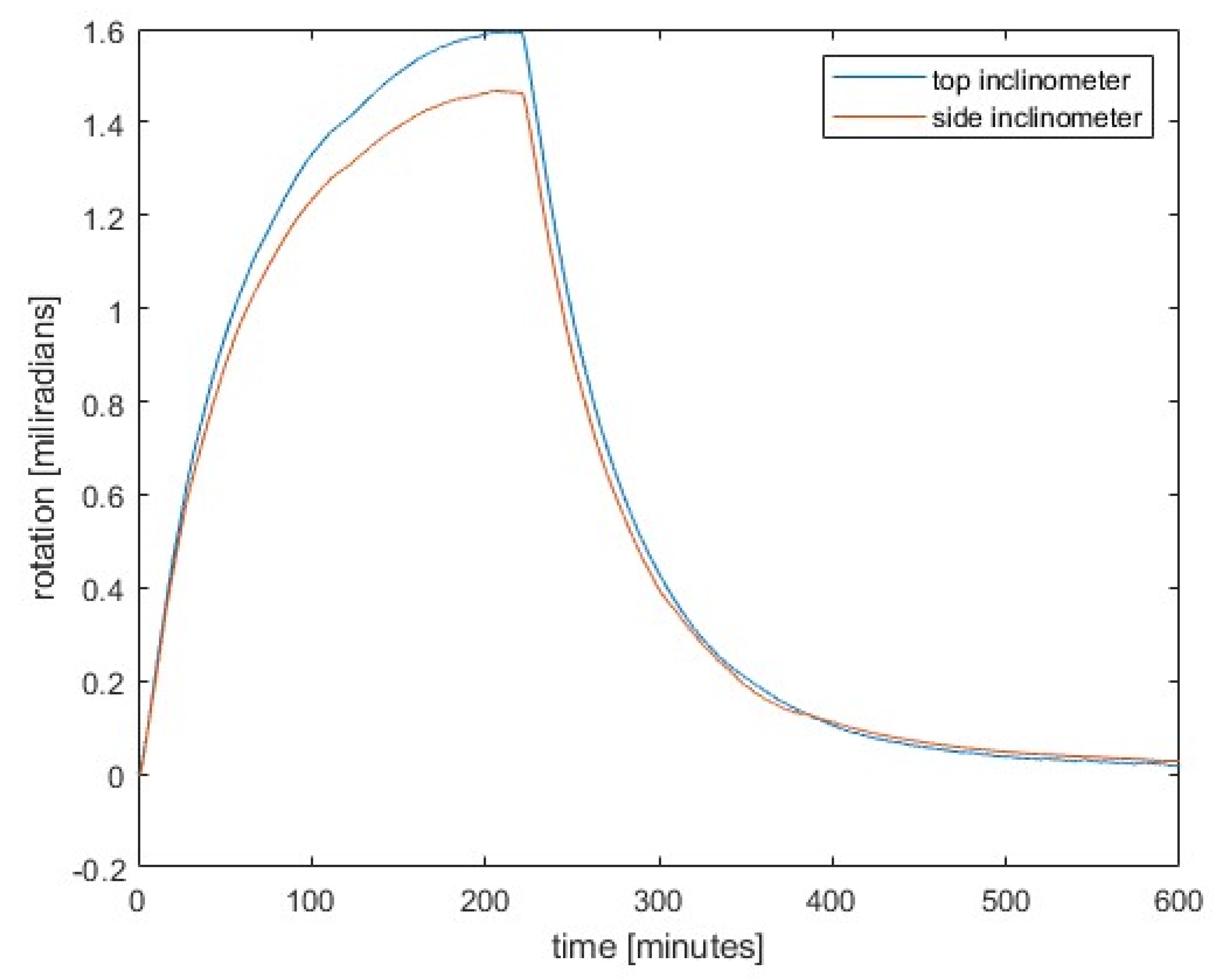
Figure 7.
Temperature changes at inclinometers.
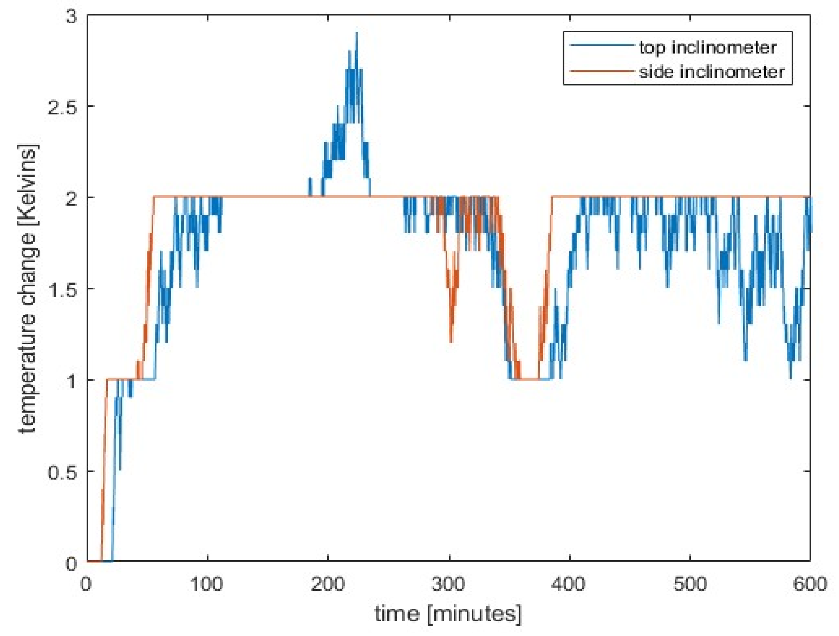
Figure 8.
Comparison of the obtained data.
Disclaimer/Publisher’s Note: The statements, opinions and data contained in all publications are solely those of the individual author(s) and contributor(s) and not of MDPI and/or the editor(s). MDPI and/or the editor(s) disclaim responsibility for any injury to people or property resulting from any ideas, methods, instructions or products referred to in the content. |
© 2025 by the authors. Licensee MDPI, Basel, Switzerland. This article is an open access article distributed under the terms and conditions of the Creative Commons Attribution (CC BY) license (http://creativecommons.org/licenses/by/4.0/).
Copyright: This open access article is published under a Creative Commons CC BY 4.0 license, which permit the free download, distribution, and reuse, provided that the author and preprint are cited in any reuse.


