1. Introduction
Heart rate monitoring (HRM) is a critical application in clinical diagnosis, personal health care, and fitness monitoring. Ongoing and precise heart rate monitoring is essential for the identification of cardiovascular defects, the treatment of chronic illness, and the maximization of physical performance. Heart rate monitoring used to be constrained to the clinical setting and necessitated bulky and expensive devices such as electrocardiograms (ECG). However, with the emergence of microcontrollers, wireless technologies, and Internet of Things (IoT), HRM has evolved into inexpensive, portable, and real-time applications for individual as well as organizational purposes [
1,
2,
3,
4].
Recent development of microcontroller-based heart rate monitoring systems has taken advantage of various sensor technologies and signal processing techniques to provide better accuracy and efficiency. Most of the HRM devices employ photoplethysmography (PPG), which is a non-invasive optical sensing method measuring blood volume changes using infrared light (Tamura et al., 2014). When light onto the skin is emitted by an infrared (IR) LED, the reflected or transmitted light is detected by a phototransistor and variations in blood flow due to the heartbeat are picked up. The resultant signal is amplified, filtered, and processed by a microcontroller to determine heart rate values. However, noise interference, motion artifacts, and power efficiency issues continue to affect measurement accuracy, necessitating continuous development of HRM technologies [
4,
5,
6,
7,
8,
9].
Three independent microcontroller-based heart rate monitoring systems have been extensively researched include Basic Microcontroller-Based HRM Systems: Low-end microcontrollers such as the PIC16F84-based instruments that convert raw sensor data to digital and display the heart rate on an LCD screen. They offer low prices but limited signal processing functions and connectivity [
10,
11,
12].
GSM-Powered HRM Systems: Highly advanced HRM systems employ the use of microcontrollers like ATMEGA32 and GSM modules to provide alerts of heart rates through SMS messages to medical staff. Such systems improve patient observation [
38] but rely on cellular networks and are not as available in real time [
13,
14,
15,
16,
17,
18].
IoT-Based HRM Systems: Modern HRM devices incorporate microcontrollers like the NodeMCU ESP8266, which are internet connected and transmit heart rate data to cloud platforms. These systems support continuous remote monitoring, real-time analysis, and synchronization with mobile applications, enhancing healthcare efficiency by a significant extent [
19,
20].
The application of IoT in HRM is particularly significant as it facilitates continuous health monitoring, incorporation of early warning systems, and seamless data exchange with healthcare experts. Studies have indicated that medical devices empowered with IoT[
39,
40,
41,
42] have assisted in the early detection of arrhythmia, which has reduced hospital readmission and improved patient outcomes [
21]. Besides, the integration of AI analytics with IoT-based HRM systems can enable predictive monitoring for health with early warnings for conditions such as atrial fibrillation or bradycardia [
22].
This study offers a comparative analysis of three microcontroller-based HRM systems, comparing their hardware configuration, signal processing[
43,
44,
45] capability, cost-effectiveness, and real-time monitoring ability. In light of the advantages and limitations of each system, this study aims to offer an insight into the future development of heart rate monitoring devices with a focus on accuracy, accessibility, and compatibility with AI-based healthcare solutions[
46,
47,
48,
49].
2. Literature Review
The evolution of heart rate monitoring (HRM) systems has grown significantly over the past decades using microcontroller-based technologies, wireless communication, and artificial intelligence (AI) technologies for real-time physiological monitoring. This review assesses the current research in HRM systems through a critical review of the available literature, with the studies organized into three broader categories: (1) microcontroller-based HRM devices, (2) IoT-based HRM systems, and (3) AI-based HRM analytics. The author, [
23,
24], has discuss the low-cost HRM device using the PIC16F84 microcontroller with an infrared (IR) LED and phototransistor to detect heartbeats. The article was centered on low-cost hardware integration but noted the disadvantage of the device’s inaccuracy in the signal due to motion artifacts.
previous designs that inclusion of the ATMEGA32 microcontroller with Analog-to-Digital Converter (ADC) and filtering based on the Fourier Transform. Their work showed greater signal accuracy but identified constraints in terms of real-time data transmission. Sharma et al. (2013) proposed an MSP430 microcontroller-based HRM system that had an OLED display and real-time processing algorithms. The outcome indicated improved power efficiency and more precise signal than the earlier versions of the microcontroller but lacked connectivity capabilities. López et al. (2015) studied a GSM-enabled microcontroller-based HRM system for remote monitoring of health. They demonstrated that patient safety was improved due to SMS-based alert systems, although GSM communication suffered from latency[
25,
26,
27].
A study employed an HRM device with a PIC18F452 microcontroller having Bluetooth communication. It established the benefits of wireless transmission but saw high power consumption, which made optimization methods to improve energy efficiency necessary. A study suggested an IoT-based HRM system based on the NodeMCU ESP8266 microcontroller and connectivity with the cloud. It concluded that Wi-Fi-based data transfer significantly improved real-time access but created problems for data security and power consumption. Research examined mobile health applications with the aid of IoT-based HRM systems, emphasizing the revolutionary extent of IoT to monitor patients remotely. The research indicated the possibility of reducing patient hospital readmissions and facilitating early detection of diseases. Network stability, as well as the problem of compatibility, however, remained an issue[
26,
27,
28].
An IoT-based wearable HRM system using Raspberry Pi and MQTT protocol for data transmission via the cloud was developed. The system offered better real-time monitoring performance compared to GSM-based systems, but under low network conditions, loss of data packets was the major drawback. Increased research further examined the intersection between telemedicine platforms and IoT-based HRM devices, expanding the role of cloud-based analysis for arrhythmia detection and data privacy and compliance concerns. Another study proposed a hybrid IoT-HRM with 5G connectivity for real-time cardiac monitoring. It demonstrated that low-latency networks enhanced data transmission efficiency, but the cost of 5G infrastructure was a major hindrance to mass adoption. The use of AI in HRM systems was also explored, focusing on machine learning algorithms for arrhythmia diagnosis. The findings indicated better diagnostic performance, but computational loads imposed constraints on real-time implementation[
29,
30,
31,
32].
Deep learning techniques were employed to process HRM data captured on smartphone sensors. The study noted the potential of AI in eliminating noise and motion artifacts but emphasized the need for proper model training based on good datasets[
25,
26,
27,
28,
29,
30,
31,
32,
33].
A multimodal AI-HRM platform was established by combining PPG and ECG signals to enhance cardiovascular monitoring. The study demonstrated fusion-based models to improve detection sensitivity but noted interoperability with existing medical devices as necessitating standardization. Another research conducted an investigation on AI implementation for wearable HRM wearables aiming at real-time anomaly detection. It emphasized adaptable algorithms for customized healthcare approach but quoted limitations incorporating computational efficiency as well as battery life[
36,
37].
Finally, a federated learning-based cloud AI architecture was suggested for HRM data analysis with enhanced privacy. The study demonstrated that sharing data could be achieved securely without compromising model performance and suggested federated learning as a promising direction for future HRM development. In conclusion, the Literature surveyed clearly identifies a clear path of advancement of HRM system development from the basic microcontroller-based systems to sophisticated IoT-embedded and AI-driven systems. While the older microcontroller-based HRM systems emphasize being cheap and minimalist, IoT-based systems shatter accessibility barriers through incorporation into the cloud. AI-powered analytics further enhance diagnostic accuracy, particularly in identifying arrhythmias and predictive care. Power efficiency, data security, and interoperability continue to be major issues. Future research must focus on improving AI models for real-time processing, IoT network robustness, and developing standardized frameworks for secure transfer of health data.
3. Proposed Methodology
The three heart rate monitoring (HRM) projects’ methodology is suggested through a step-by-step approach involving hardware integration, signal processing, data transmission, and real-time monitoring. Each system—(1) Basic Microcontroller-Based HRM, (2) GSM-Enabled HRM, and (3) IoT-Enabled HRM—is integrated with different microcontrollers, communication technologies, and processing techniques for enhancing the accuracy of heart rate calculation and usability.
- 1.
Fundamental Microcontroller-Based Heart Rate Monitoring System
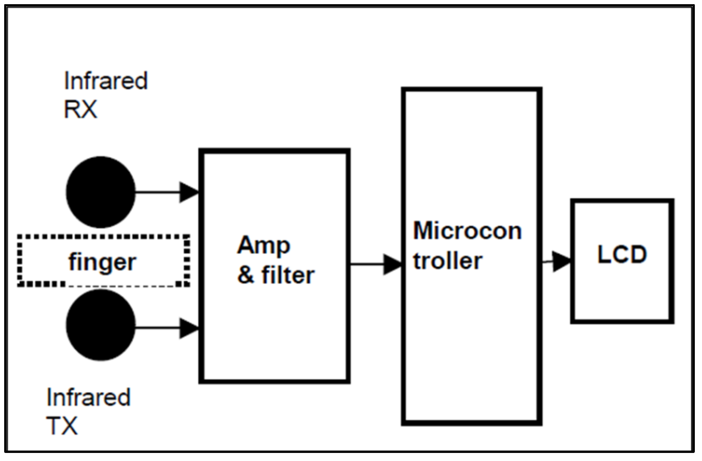
The first project utilizes a PIC16F84 microcontroller to process heart rate signals acquired with an infrared (IR) LED and a phototransistor sensor. When a user places his or her fingertip on the sensor, the IR LED emits light, and the phototransistor detects variations in light absorption that are proportional to blood volume variations in the capillaries. These oscillations generate an analog signal, which is amplified using operational amplifiers (Op-Amps) and filtered using a low-pass filter to eliminate high-frequency noise. The microcontroller then counts the number of pulses within a defined time window and calculates the heart rate in beats per minute (BPM). The computed heart rate value is then displayed on a 16x2 LCD display for user feedback. A push-button switch is an input control mechanism for the users to start or restart the measurement. The system as a whole provides a cost-effective, low-power HRM system that is well suited for home monitoring. Yet, it is not very practical for remote monitoring in real-time because the system does not support real-time data transmission.
Figure 1.
Block diagram of the measuring device. Source: (Ibrahim & Buruncuk, 2005).
Figure 1.
Block diagram of the measuring device. Source: (Ibrahim & Buruncuk, 2005).
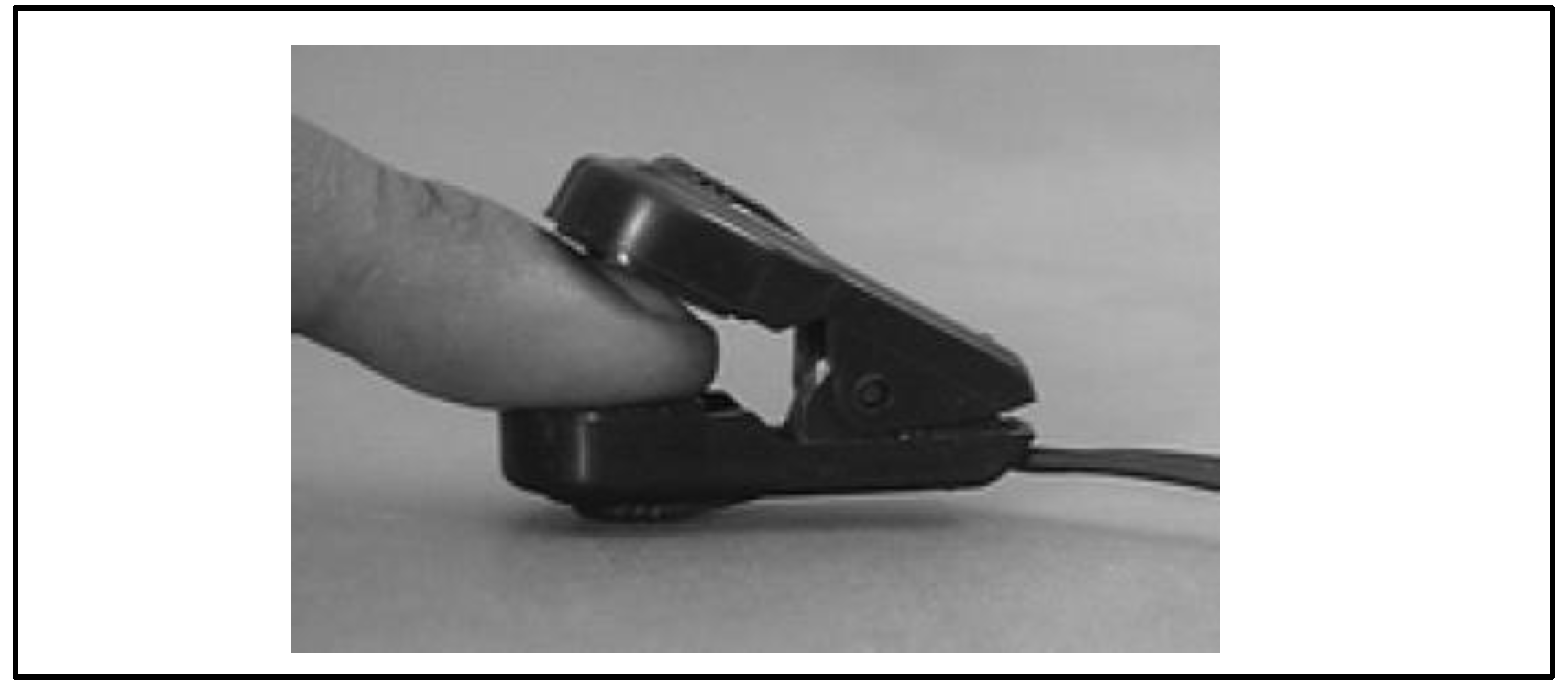
Figure 2.
IR transmitter and receiver attached to the finger. Source: (Ibrahim & Buruncuk, 2005).
Figure 2.
IR transmitter and receiver attached to the finger. Source: (Ibrahim & Buruncuk, 2005).
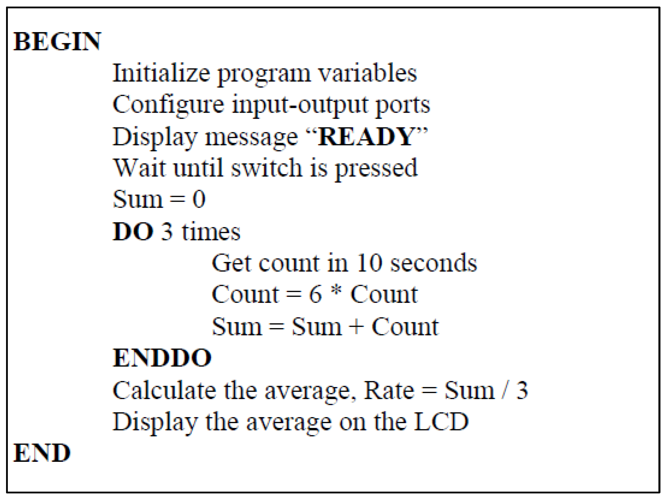
Figure 3.
Pseudocode for Project 1. Source: (Ibrahim & Buruncuk, 2005).
Figure 3.
Pseudocode for Project 1. Source: (Ibrahim & Buruncuk, 2005).
- 2.
GSM-Enabled Heart Rate Monitoring System
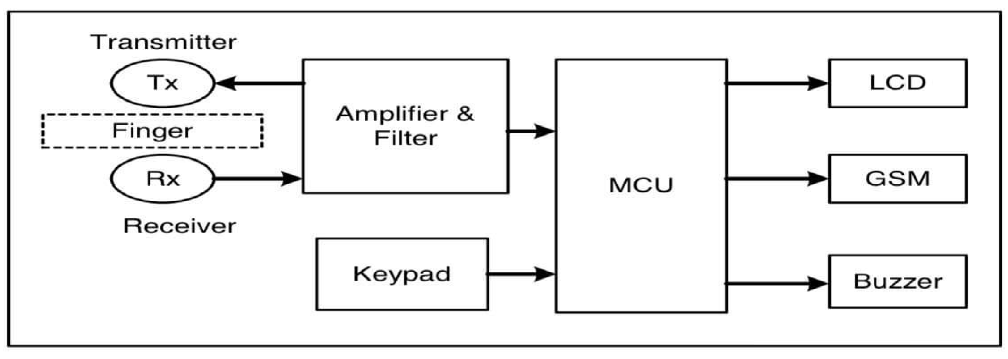
The second project enhances heart rate monitoring by utilizing a GSM modem along with an ATMEGA32 microcontroller to enable remote data transmission. The system is once more founded on the utilization of an IR LED and phototransistor to sense the pulse, followed by the utilization of Op-Amps and low-pass filtering to clean the signal. The most significant enhancement in this system is the incorporation of an Analog-to-Digital Converter (ADC) in the microcontroller, which translates the filtered signal into digital form to enable processing.
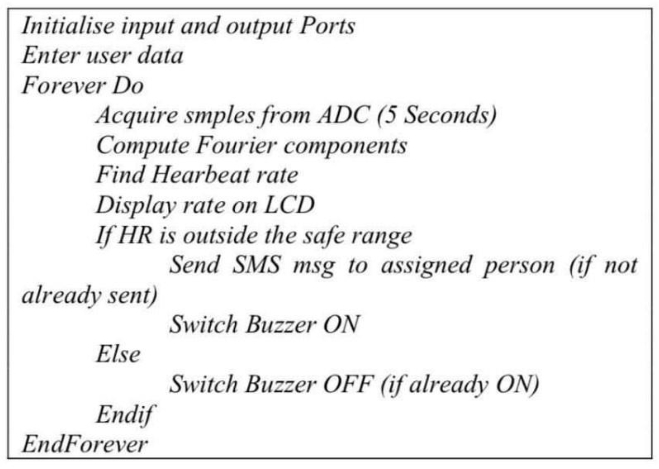
Upon the determination of heart rate, the microcontroller is referenced against an age and sex-determined safety level. Whenever a heart rate value is outside of normal ranges (e.g., below 50 BPM or over 120 BPM), a message of alarm (SMS) is transmitted through the GSM module to a predefined guardian or healthcare practitioner. Moreover, a buzzer alarm presents out-of-tolerance readings to the user. A keypad is integrated into the system to allow users to key in personal information, such as name and emergency contact numbers, to allow customized alerts.
The project provides an improvement of huge magnitude over the original system with the ability to monitor patients real-time through the use of cellular communication. Using GSM networks also has the implication of latency as well as high operational costs based on SMS charges.
Figure 4.
Block diagram of the HRM system.
Figure 4.
Block diagram of the HRM system.
Figure 5.
Pseudocode for Project 2. Source: (Babiker, Abdel-Khair, & Elbasheer, 2011).
Figure 5.
Pseudocode for Project 2. Source: (Babiker, Abdel-Khair, & Elbasheer, 2011).
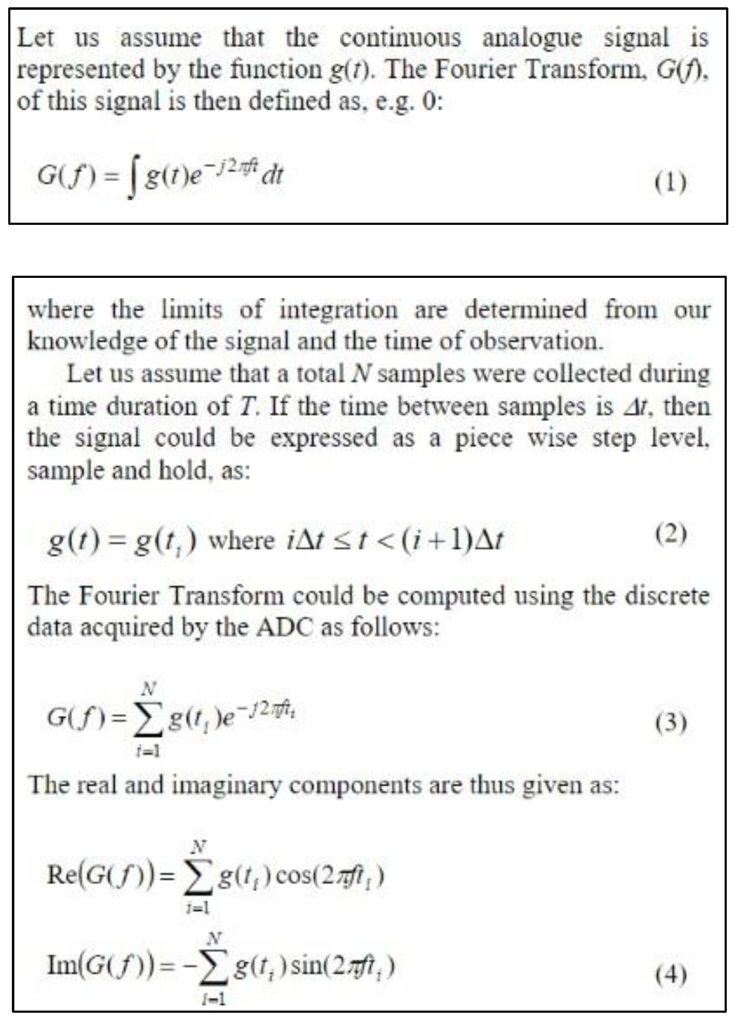
- 1.
Computation of Fourier Components: Following data acquisition, the software computes the Fourier components of the acquired ECG signal using Discrete Fourier Transform
Figure 6 The Fourier analysis process as per the journal article. Source: (Babiker, Abdel-Khair, & Elbasheer, 2011)
Figure 6.
Method for Fourier Transform. Source: (Babiker, Abdel-Khair, & Elbasheer, 2011).
Figure 6.
Method for Fourier Transform. Source: (Babiker, Abdel-Khair, & Elbasheer, 2011).
3. IoT-Based Heart Rate Monitoring System
The third project employs Internet of Things (IoT) technology to deliver real-time cloud-based heart rate monitoring. The system is designed with a NodeMCU ESP8266 microcontroller, which is pre-fitted with an embedded Wi-Fi module for easy data transmission. The HRM process is similarly organized as in the previous projects, employing an IR-based Easy Pulse Sensor, Op-Amps, and filtering for noise rejection. However, instead of simply displaying the heart rate on an LCD or SMS alerting, this system uploads the heart rate readings to a cloud storage platform (such as Firebase or AWS).
Arduino Integrated Development Environment (IDE) is used for programming the NodeMCU, defining parameters for real-time data acquisition and communication. The system continuously samples the heart rate readings and sends updates on a web-based dashboard or mobile application. Medical practitioners and patients can see real-time data from any place, and remote monitoring of patients is made possible at any time. Where heart rate strays from within normal limits, the system will automatically send notice by email or push messages to caregivers.
A 1.2-inch OLED display provides users with immediate feedback, a warning message customizable through a USB keyboard. Predictive analytics is facilitated in its cloud-based platform through the use of AI-driven algorithms that detect anomalies in heart rhythms for the early diagnosis of cardiovascular conditions. The largest disadvantage of this system is its reliance on good Wi-Fi connectivity, thus not as convenient where internet infrastructure is poor.
Comparison and Optimization Strategies
There are conflicting strengths and vulnerabilities of each one of the three suggested systems of HRM. The lowest energy and cost-saving microcontroller-based system is most basic but excludes remote monitoring aspects. The GSM-based system gives the highest levels of remote accessibility in the forms of SMS updates but entails added costs and potential network delays. The IoT-based system offers the highest-end attributes, including live cloud integration and analytics via AI, but requires stable internet coverage.
To improve the efficiency of such systems, the following can be achieved:
Hybrid Communication Strategy: Combination of GSM and IoT for areas with spasmodic Wi-Fi coverage.
AI-Driven Signal Filtering: Utilizing machine learning techniques to reduce motion artifacts in heart rate recordings.
Power Management: Switching into low-power modes of microcontrollers for extending battery life for extended monitoring.
Security Data Measures: Data encryption while in transit to protect patient confidentiality in cloud-based HRM.
These developments will ensure the production of more accurate, reliable, and affordable heart rate monitoring technologies for enhanced personal healthcare management and clinical diagnostics.
- (a)
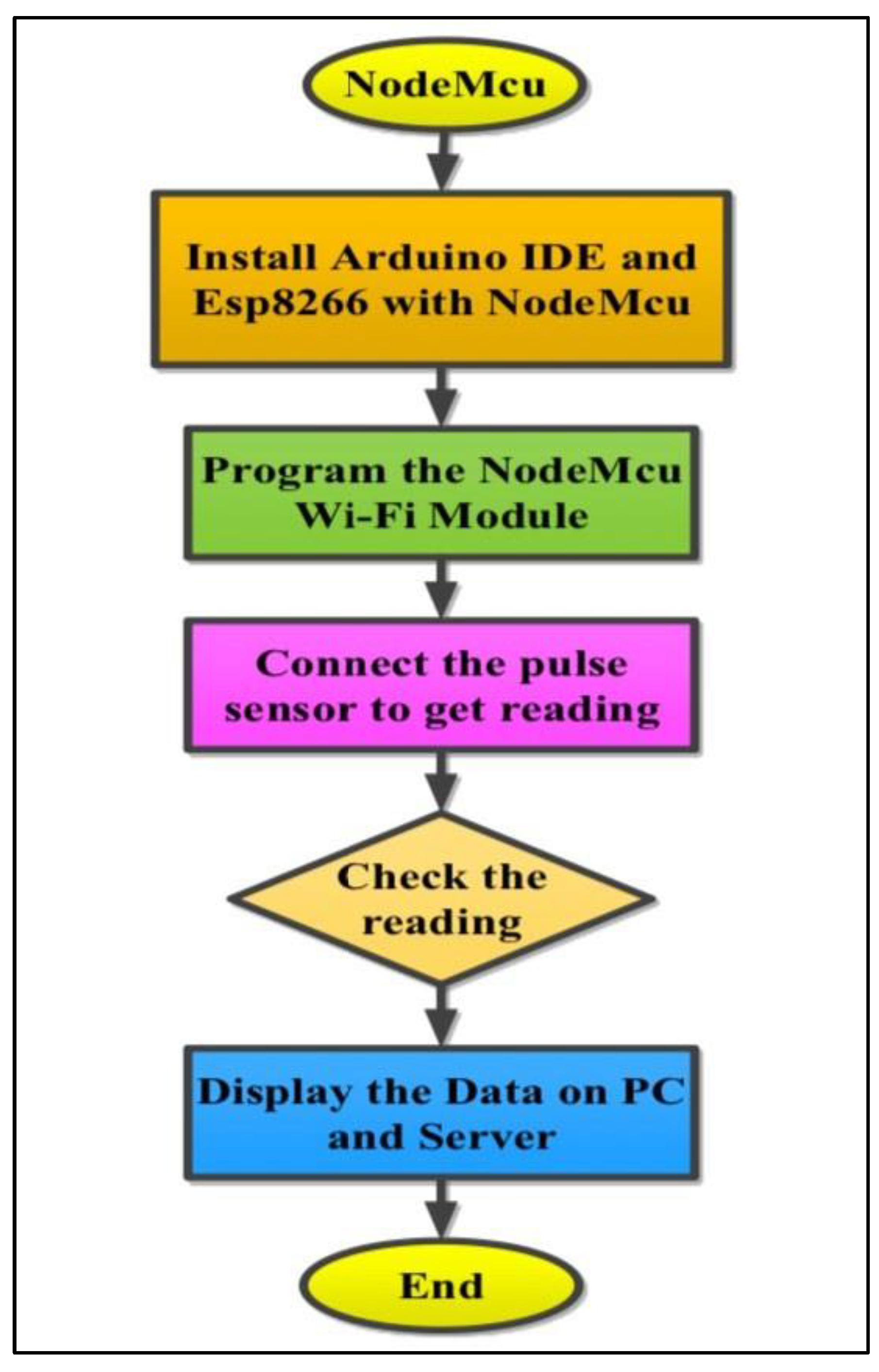
Built in Wi-Fi module: uses the internet to send data to its intended location. The Esp8266 Wi-Fi module will link the network to a router that will give a code and send online sensor data that can be accessed from any location via the internet.
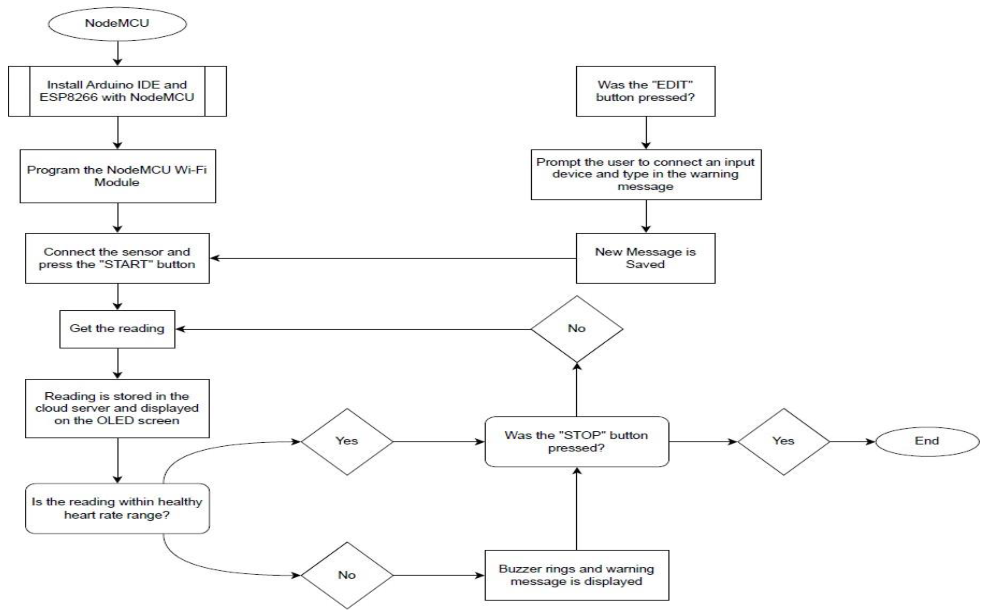
Figure 7.
Flowchart for Project 3. Source: (Abdullah, 2019).
Figure 7.
Flowchart for Project 3. Source: (Abdullah, 2019).
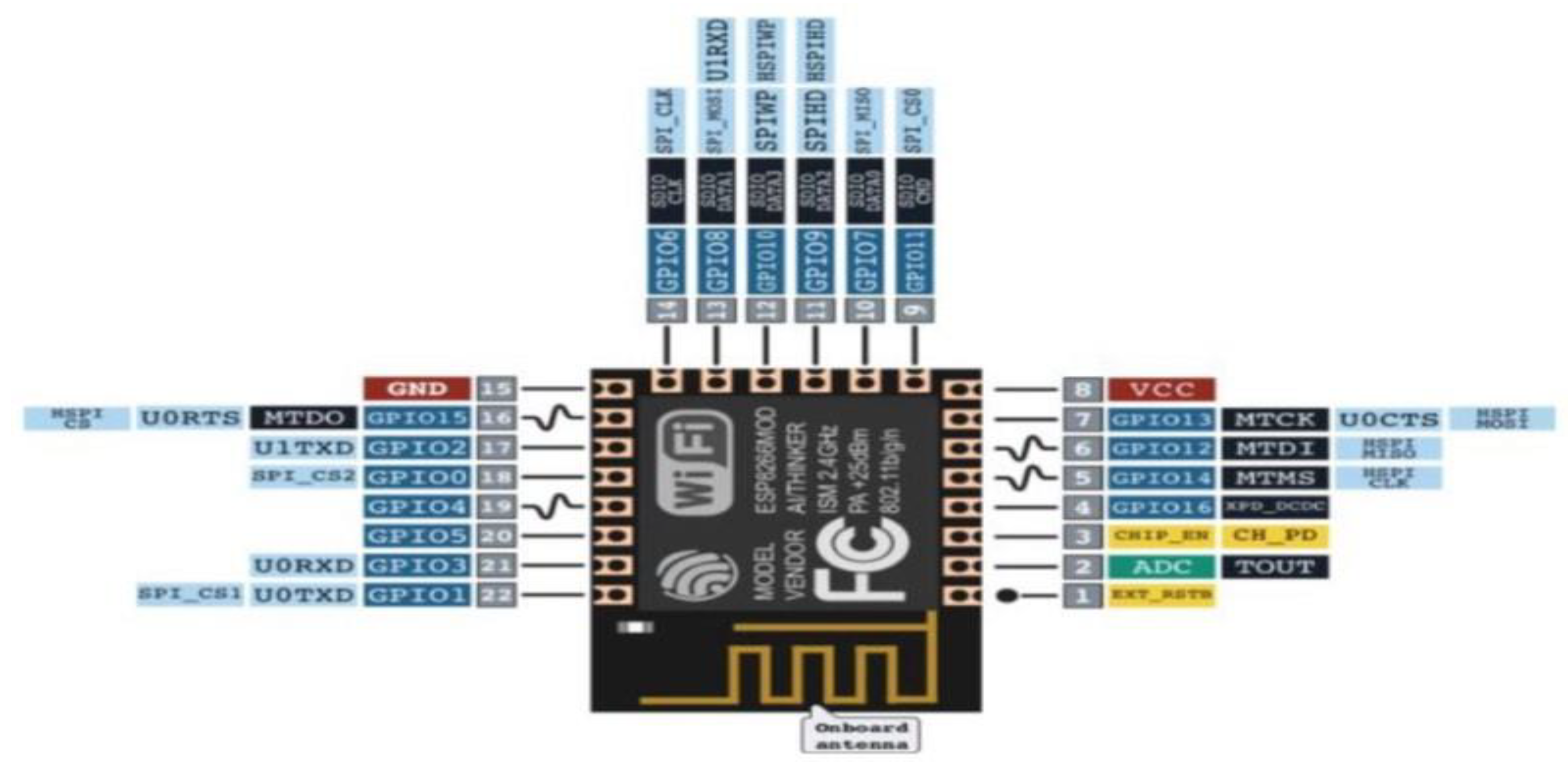
- (b)
NodeMCU board: Contains the Esp8266 Wi-Fi chip on the NodeMCU board. It has the fundamental components of a computer, including an operating system, a Wi-Fi chip, RAM, and CPU. It has a PCB antenna, 10 digital ports D0-D10 with 1 analog port A0, SPI connection, and pulse width modulation implementation.
Figure 8.
NodeMcu Board. Source: (Abdullah, 2019).
Figure 8.
NodeMcu Board. Source: (Abdullah, 2019).
Figure 9.
Esp8266 Wi-Fi chip. Source: (Abdullah, 2019).
Figure 9.
Esp8266 Wi-Fi chip. Source: (Abdullah, 2019).
- (c)
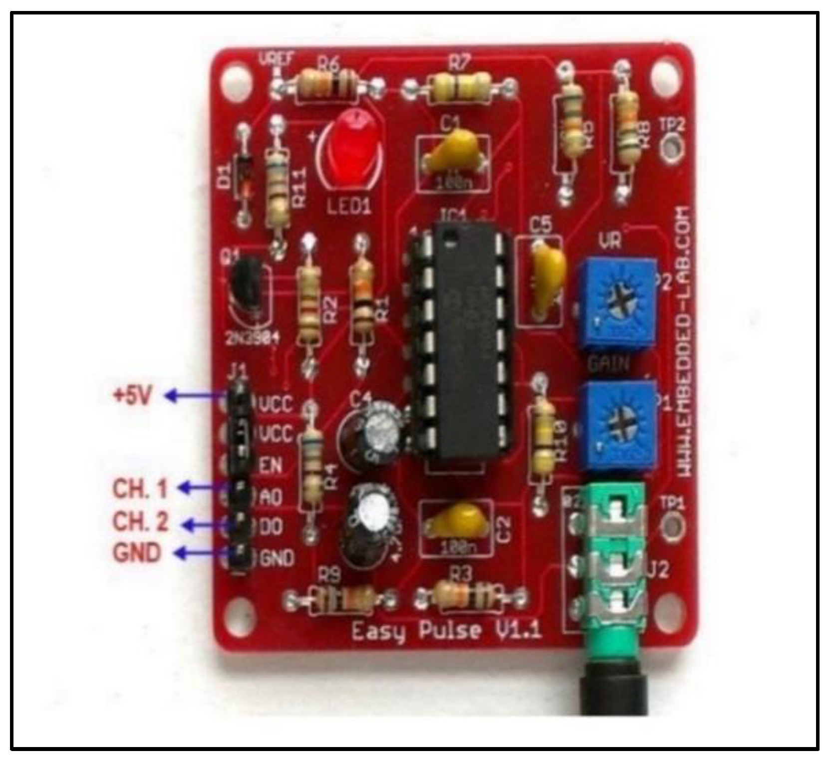
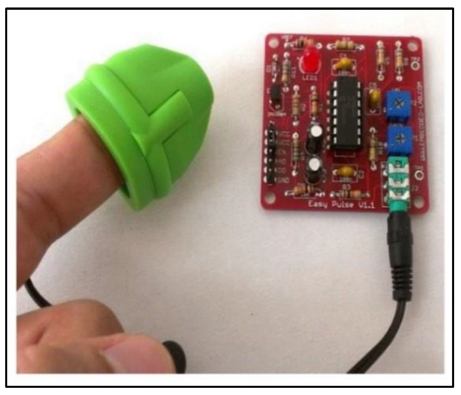
Easy pulse sensor: to detect the cardio-vascular signal from the skin surface. It employs infrared ray light to irradiate the skin surface. Any microcontroller platform such as PIC and AVR can be interfaced with it. (Embedded-Lab, 2013)
Figure 10.
General shape of the sensor. Source: (Abdullah, 2019).
Figure 10.
General shape of the sensor. Source: (Abdullah, 2019).
Figure 11.
Easy pulse board connections. Source: (Abdullah, 2019).
Figure 11.
Easy pulse board connections. Source: (Abdullah, 2019).
- (d)
OLED Display 1.2 inch: organic light emitting diodes is an LED technology. OLED immediately releases colored lights and it lowers power consumption while still producing better quality pictures.
The system utilizes a NodeMCU board with an ESP8266 Wi-Fi module to compute and transmit heart rate values, utilizing an Easy Pulse Sensor V1.1 to detect pulse variations via the skin. The system operates by either tracking peaks in the PPG waveform or counting the frequency of the digital output waveform to derive heart rate. Featured with the Arduino Integrated Development Environment (IDE), the board is designed to read and process pulse information and display the result on an OLED screen. The built-in Wi-Fi functionality provides smooth data transfer to a distant server or PC, enabling timely health tracking and integrating Internet of Things (IoT) technologies into healthcare systems. Unlike other IoT microcontroller solutions, this is both reliable and cost-effective, making it possible to communicate with smart health devices for heart rate logging and remote monitoring. The cost of the project is estimated at $43.55+, with the NodeMCU model being $7.99, the Easy Pulse Sensor V1.1 being $24.9, and the OLED display being around $17.25, without additional charges for components like power supplies and cables.
Table 1.
Comparison between task_1, task_2, and task_3.
Table 1.
Comparison between task_1, task_2, and task_3.
| Feature |
Task_1 |
Task_2 |
Task_3 |
| Microcontroller Used |
PIC16F84 |
ATMEGA32 |
NodeMCU ESP8266 Wi-Fi |
| Internet Connectivity |
No |
No |
Yes |
| Total Cost of Components |
Very Low |
Low |
High |
| Use of Fourier Transform |
No |
Yes |
NA (Not Specified) |
This research employed a basic 8-bit microcontroller PIC16F84, which had minimal processing power but rendered the heart rate measurement solution affordable. Project 2 employed the ATmega32, an 8-bit microcontroller with higher memory and low power consumption, which was better suited for other processing requirements. Project 3 used the NodeMCU ESP8266, a 32-bit Wi-Fi microcontroller, which is broadly used in IoT applications and contains various GPIOs and support for Lua and Arduino IDE, the most advanced among the three. For internet connectivity, Project 1 did not have any network functionality, while Project 2 used a GSM modem for receiving SMS alerts but did not use internet-based data transmission. Project 3 employed Wi-Fi for real-time communication between sensors and the cloud. On the integration aspect of IoT, Project 1 was not an IoT-based project, while Project 2 applied IoT concepts in that it used SMS to transmit heart rate measurements. Project 3 was entirely IoT-based, where internet access was utilized for uploading and monitoring heart rate readings remotely. On the cost front, Project 1 was a cost-effective one, with an inexpensive approach (~$20), while Project 2 aimed at balancing functionality and affordability, possibly being cheaper than Project 3 since it employed cheaper hardware. Project 3, with the most advanced components, was the most expensive (~$43.55+), owing to Wi-Fi capabilities and a better display. In signal processing, Project 1 did not have Fourier Transform, but Project 2 had Fourier Transform in ECG signal smoothing. Project 3, despite its IoT capabilities, did not employ Fourier Transform in data processing.
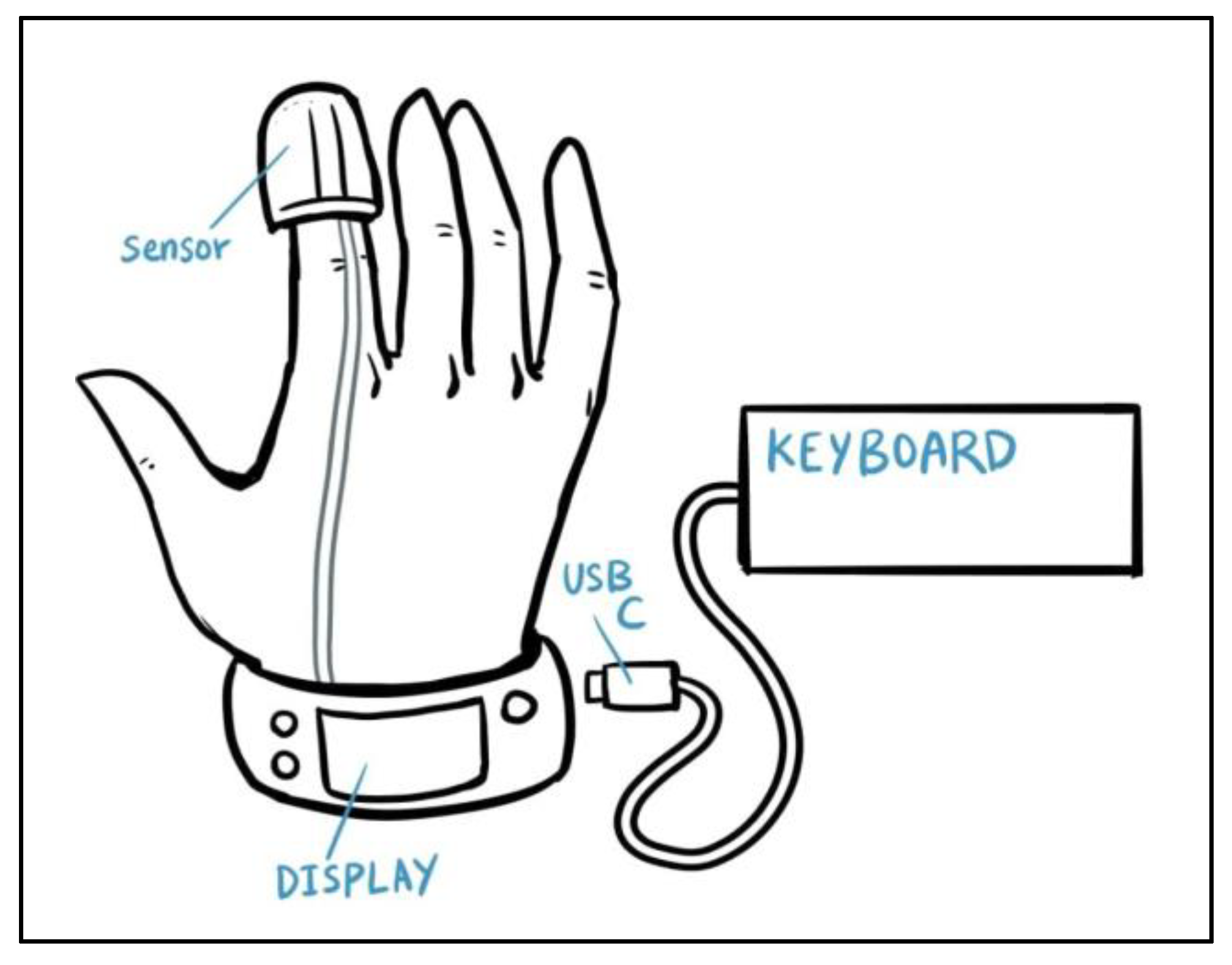
4. PulsePal – Sync with Your Heart, anytime, anywhere
PulsePal is a convenient and reliable heart rate monitoring device that connects to the cloud so that users can save and share pulse data with caretakers and health professionals. PulsePal has a buzzer alarm system to alert users whenever the heart rate exits a healthy range, which is determined based on age and gender using UK-standard HRMAX formulas. Once the abnormal heart rate is observed for a set duration of time, a custom warning message appears alongside the buzzer to guide users on the next course of action. The message can be edited via a USB keyboard to enable custom warnings. In alignment with SDG 3: Health and Well-being, PulsePal is a low-cost home-based health screening tool, particularly for individuals in remote communities or those who are mobility-impaired. Additionally, it plays a crucial role in the early detection of cardiovascular arrhythmias, one of the significant causes of strokes, heart failure, and cardiac arrest, accounting for nearly half of all cardiovascular-related deaths in industrialized countries. Most of the heart rate monitors, such as Project 1, utilize basic signal filtering, but PulsePal, derived from Project 2, uses Fourier Transform to eliminate zero-crossing errors and noise filtering for higher accuracy. Hardware components include a rechargeable battery for portability, three push-button switches (Start, Stop, Edit Message), a USB keyboard to edit the message, operational amplifiers and low-pass filters for signal conditioning, and a Wi-Fi module (ESP8266) for internet-based data communication. The NodeMCU board serves as the primary microcontroller for processing data, communication with sensors, and Fourier Transform calculations. The Easy Pulse Sensor detects heart rate via infrared light absorption, and a 1.2-inch OLED screen displays real-time heart rate or alert notifications. It is programmed via the Arduino IDE, allowing real-time data collection, cloud storage, and analysis for remote health monitoring. Cloud connectivity provides access to the heart rate data across devices, making long-term health monitoring and predictive analytics possible.
Figure 17.
Pseudocode for PulsePal.
Figure 17.
Pseudocode for PulsePal.
Figure 18.
PulsePal device.
Figure 18.
PulsePal device.
5. Memory Hierarchy
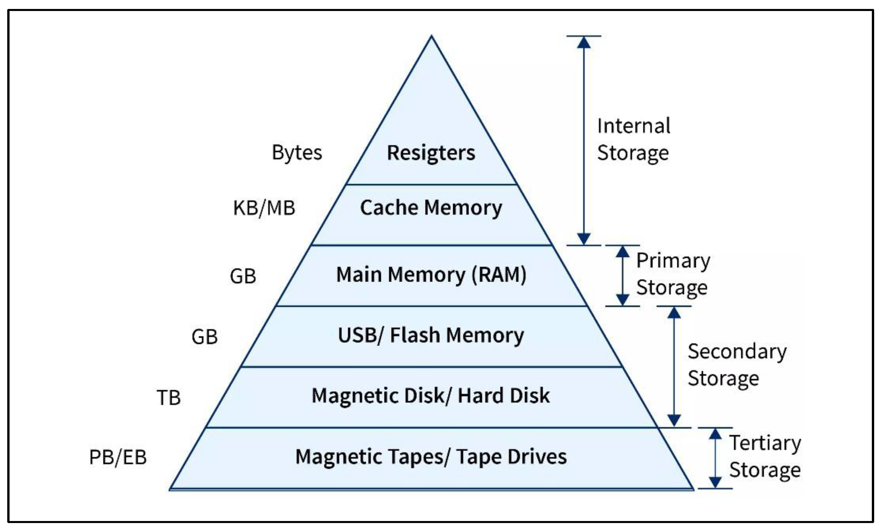
Memory hierarchy is a central component of computer systems, partitioning storage into a well-organized hierarchy based on response time, performance, and control technologies in an effort to maximize data access and system effectiveness. It is pyramid-like, where each stage consists of various types of memory, starting from stage 0 (CPU registers) to stage 4 (tertiary storage), including devices like optical discs and magnetic tapes. The hierarchy ensures efficient operation by minimizing data access time and maximizing overall performance. CPU registers are on top because they provide the lowest access times, and RAM and cache memory are intermediaries to strike a balance between speed and storage. Without this structured memory system, there would be an enormous speed disparity between the CPU and main memory, leading to system slowdowns. Apart from this, memory hierarchy also saves money in the sense that it can utilize cheaper memory for less frequently accessed data but retains high-speed expensive memory for crucial applications. Cache memory, while being the fastest, is also the most expensive, whereas secondary and tertiary storage medium have enormous storing capacity at much cheaper prices. Besides, energy efficiency is essential in memory hierarchy because closeness to the CPU boosts energy usage due to higher access speeds. Dynamic Voltage and Frequency Scaling (DVFS) can be used to scale power usage based on workload, enhancing system efficiency. Among the most significant features that describe memory hierarchy are capacity, access time, performance, cost per bit, and volatility. Capacity refers to the stored amount of data, and this increases as we move down the hierarchy from registers to secondary storage (Awati & Wigmore, 2022). Access time is also an important factor, with immediate access to data being provided by registers, while secondary storage like magnetic tapes has much higher access times (GeeksforGeeks, 2023). Performance is highly dependent on memory hierarchy because early computing systems lacked a clear model of memory, resulting in inefficiency due to the performance difference between CPU registers and main memory (BYJU’S, n.d.). Hierarchy improves performance by reducing bottlenecks and prioritizing high-frequency accessed information (Awati & Wigmore, 2022). The price per bit decreases as the storage sizes increase, with the registers and the cache being the most expensive while external storage devices are a cheap alternative (ElProCus, n.d.). Lastly, volatility distinguishes between temporary memory (RAM, cache) and non-volatile memory (ROM, secondary storage) so that important system information is not deleted even when there is a loss of power.
Figure 19.
Memory Hierarchy Pyramid. Source: (Shukla, 2023).
Figure 19.
Memory Hierarchy Pyramid. Source: (Shukla, 2023).
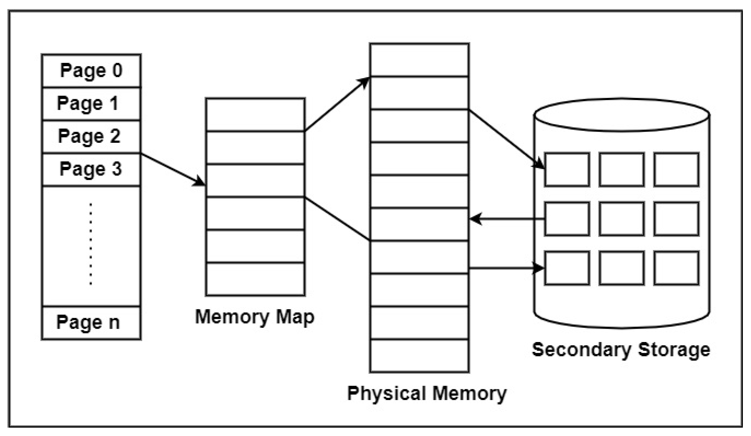
Figure 20.
Virtual Memory in Operating Systems. Source: (Ginni, 2021).
Figure 20.
Virtual Memory in Operating Systems. Source: (Ginni, 2021).
Virtual memory is essential to memory protection and management and allows the operating system to use secondary storage (HDD/SSD) as an extension of RAM, allowing computers to run more programs than physically installed memory allows. It prevents performance bottlenecks by transferring inactive data from RAM to disk space so that active processes can make use of free space. The OS achieves this through the utilization of page files or swap files, where overflow data is stored temporarily. Virtual memory operates on the fly with such algorithms as FIFO (First In, First Out), LRU (Least Recently Used), and OPT (Optimal Page Replacement) to support data access order and optimize use of memory. Even though virtual memory is typically accessed more slowly than physical RAM, it enhances performance by bringing into memory only the portions of a program that are needed at a given time. Virtual memory also enhances security and protection of memory as it isolates processes in their own virtual address space, thus preventing unauthorized access or data corruption between programs.
It is fundamental to computer architecture to understand the difference between RAM and ROM. RAM (Random Access Memory) is a volatile form of main memory that stores program instructions and data being used at the moment in a temporary manner for instant access by the CPU. It allows reading, writing, and deleting data but erases all stored data upon power disconnection. RAM is also classified into Static RAM (SRAM) and Dynamic RAM (DRAM). SRAM, composed of flip-flop circuits, retains data as long as power is being provided, with faster access but at an increased cost. DRAM utilizes capacitors and transistors to retain data, requiring repeated refresh cycles due to slow leakage of charge, thus being more affordable but slower than SRAM. On the contrary, ROM or Read-Only Memory is a storage device that has permanent system data and firmware, which preserves essential instructions regardless of power failure. ROM exists in various types, i.e., Mask ROM (MROM), in which it gets programmed permanently when manufactured, Programmable ROM (PROM), in which programming is done a single time, Erasable Programmable ROM (EPROM), in which removal of programming by ultraviolet (UV) is possible, and Electrically Erasable Programmable ROM (EEPROM), in which one can reprogram without taking it out of the circuit (Toppr, n.d.). Briefly, RAM holds active processes of the computer system and performs multitasking, while ROM houses significant firmware and booting procedures, both acting as essential tasks in computer activity.
Table 2.
The difference between RAM and ROM.
Table 2.
The difference between RAM and ROM.
| Characteristic |
Random Access Memory (RAM) |
Read-Only Memory (ROM) |
| Function |
Temporarily stores data and program instructions used by the CPU |
Permanently stores essential data and software for system operations |
| Volatility |
Volatile memory; data is erased when power is turned off |
Non-volatile memory; data is retained even when the power is off |
| Accessibility |
Used for both reading and writing |
Used only for reading |
| Data Retention |
Retains data temporarily and is cleared when powered off |
Data is permanently programmed onto the chip and does not change over time |
| Use Cases |
Well-suited for program execution and data manipulation |
Stores firmware and software necessary for system functionality |
| Data Persistence |
Data is lost when power is turned off |
Data is retained even when the power is off |
| Speed |
Faster than ROM |
Slower than RAM |
| Chip Size |
Ranges from 1 to 256 gigabytes per chip (larger than ROM) |
Ranges from 4 to 8 megabytes per chip (smaller than RAM) |
| Cost |
More expensive than ROM |
More cost-effective than RAM |
| Example |
DRAM, SRAM |
MROM, PROM, EPROM, EEPROM |
In conclusion, RAM and ROM are parts of a computer system that serve different purposes and functions. RAM is the computer’s temporary storage, literally keeping data in order to carry out present operations and tasks. On the other hand, ROM is the computer’s permanent data and instruction storage, serving as the fundamental instructions for the use of the computer. The correct distinction between these different types of memory is very important for proper operation of a computer system.
6. Logic Circuit Design for Automation and Control Systems
The siren control system of the factory glove is coded to be turned on under specified conditions to alert workers when they should leave work. The siren must be turned on under two conditions: (1) when it is already midnight (12 AM) and all machines are off or (2) when it is Monday, production for the day is complete, and all the machines are off. In order to achieve this, a logic circuit is formed using four input variables: A (HIGH when it is after 12 AM), B (HIGH when all machines are turned off), C (HIGH when it is Monday), and D (HIGH when the production run ends). The corresponding Boolean equation for the circuit is determined to be X = AB + BCD, and this is verified by a truth table that dictates the possible inputs and outputs. The sum-of-products (SOP) output expression is simplified to X = AB + BCD, and this verifies that the siren will only sound under the conditions specified. Lastly, the implementation of the logic circuit is built utilizing AND and OR gates to provide the desired output.
There is one dedicated logic circuit which generates an output of HIGH only when the level of the three input values is the same. With three inputs (A, B, and C), the circuit produces an output X = A̅B̅C̅ + ABC, i.e., HIGH output whenever all inputs are 0 or all inputs are 1. The truth table confirms this behavior, and since the SOP form is already simplest form, the SOP form itself is directly realized by using AND, NOT, and OR gates to obtain the desired logic function.
For the control of traffic lights, a logic circuit is employed to switch on the East-West (E-W) and North-South (N-S) traffic lights based on the availability of vehicles at an intersection. Four inputs (A, B, C, and D) are utilized to represent the availability of vehicles in different lanes. The E-W light is green if both lanes C and D are occupied if either C or D is occupied but A and B are not both occupied, or if there are no vehicles. The N-S light is green if both lanes A and B are occupied but C and D are not occupied, or if either A or B is occupied while C and D are both vacant. The sum-of-products (SOP) terms of both the lights are solved and minimized to make it more effective. Traffic light control logic is utilized from AND, OR, and NOT gates for smooth traffic flow at the intersection.
A dedicated circuit is employed to determine the optimal sleeping conditions, and it will provide a HIGH output only if the light is off, and the majority of the other conditions (caffeine consumption, screen usage prior to sleep, and temperature above 23 °C) are false. The inputs are A (light status), B (caffeine consumption), C (screen usage), and D (temperature). The Boolean equation X = A̅B̅C̅ + A̅B̅D̅ + A̅C̅D̅ is derived, reduced, and verified using a truth table. The circuit is then implemented using logic gates to decide accurately whether sleeping conditions are ideal.
| A |
B |
C |
D |
AB |
BCD |
X = AB + BCD
|
| 0 |
0 |
0 |
0 |
0 |
0 |
0 |
| 0 |
0 |
0 |
1 |
0 |
0 |
0 |
| 0 |
0 |
1 |
0 |
0 |
0 |
0 |
| 0 |
0 |
1 |
1 |
0 |
0 |
0 |
| 0 |
1 |
0 |
0 |
0 |
0 |
0 |
| 0 |
1 |
0 |
1 |
0 |
0 |
0 |
| 0 |
1 |
1 |
0 |
0 |
0 |
0 |
| 0 |
1 |
1 |
1 |
0 |
1 |
1 |
| 1 |
0 |
0 |
0 |
0 |
0 |
0 |
| 1 |
0 |
0 |
1 |
0 |
0 |
0 |
| 1 |
0 |
1 |
0 |
0 |
0 |
0 |
| 1 |
0 |
1 |
1 |
0 |
0 |
0 |
| 1 |
1 |
0 |
0 |
1 |
0 |
1 |
| 1 |
1 |
0 |
1 |
1 |
0 |
1 |
| 1 |
1 |
1 |
0 |
1 |
0 |
1 |
| 1 |
1 |
1 |
1 |
1 |
1 |
1 |
| A |
B |
C |
A� |
B� |
C� |
ABC |
A�B�C� |
X = ABC + A�B�C� |
| 0 |
0 |
0 |
1 |
1 |
1 |
0 |
1 |
1 |
| 0 |
0 |
1 |
1 |
1 |
0 |
0 |
0 |
0 |
| 0 |
1 |
0 |
1 |
0 |
1 |
0 |
0 |
0 |
| 0 |
1 |
1 |
1 |
0 |
0 |
0 |
0 |
0 |
| 1 |
0 |
0 |
0 |
1 |
1 |
0 |
0 |
0 |
| 1 |
0 |
1 |
0 |
1 |
0 |
0 |
0 |
0 |
| 1 |
1 |
0 |
0 |
0 |
1 |
0 |
0 |
0 |
| 1 |
1 |
1 |
0 |
0 |
0 |
1 |
0 |
1 |
| A |
B |
C |
D |
AB |
A + B
|
CD |
C + D
|
E-W Light |
N-S Light |
| 0 |
0 |
0 |
0 |
0 |
0 |
0 |
0 |
1 |
0 |
| 0 |
0 |
0 |
1 |
0 |
0 |
0 |
1 |
1 |
0 |
| 0 |
0 |
1 |
0 |
0 |
0 |
0 |
1 |
1 |
0 |
| 0 |
0 |
1 |
1 |
0 |
0 |
1 |
1 |
1 |
0 |
| 0 |
1 |
0 |
0 |
0 |
1 |
0 |
0 |
0 |
1 |
| 0 |
1 |
0 |
1 |
0 |
1 |
0 |
1 |
1 |
0 |
| 0 |
1 |
1 |
0 |
0 |
1 |
0 |
1 |
1 |
0 |
| 0 |
1 |
1 |
1 |
0 |
1 |
1 |
1 |
1 |
0 |
| 1 |
0 |
0 |
0 |
0 |
1 |
0 |
0 |
0 |
1 |
| 1 |
0 |
0 |
1 |
0 |
1 |
0 |
1 |
1 |
0 |
| 1 |
0 |
1 |
0 |
0 |
1 |
0 |
1 |
1 |
0 |
| 1 |
0 |
1 |
1 |
0 |
1 |
1 |
1 |
1 |
0 |
| 1 |
1 |
0 |
0 |
1 |
1 |
0 |
0 |
0 |
1 |
| 1 |
1 |
0 |
1 |
1 |
1 |
0 |
1 |
0 |
1 |
| 1 |
1 |
1 |
0 |
1 |
1 |
0 |
1 |
0 |
1 |
| 1 |
1 |
1 |
1 |
1 |
1 |
1 |
1 |
1 |
0 |
| A |
B |
C |
D |
A� |
B� |
C� |
D� |
A�B�C� |
A�B�D� |
A�C�D� |
A�B�C�D� |
X = A�B�C� + A�B�D� + A�C�D� + A�B�C�D� |
| 0 |
0 |
0 |
0 |
1 |
1 |
1 |
1 |
1 |
1 |
1 |
1 |
1 |
| 0 |
0 |
0 |
1 |
1 |
1 |
1 |
0 |
1 |
0 |
0 |
0 |
1 |
| 0 |
0 |
1 |
0 |
1 |
1 |
0 |
1 |
0 |
1 |
0 |
0 |
1 |
| 0 |
0 |
1 |
1 |
1 |
1 |
0 |
0 |
0 |
0 |
0 |
0 |
0 |
| 0 |
1 |
0 |
0 |
1 |
0 |
1 |
1 |
0 |
0 |
1 |
0 |
1 |
| 0 |
1 |
0 |
1 |
1 |
0 |
1 |
0 |
0 |
0 |
0 |
0 |
0 |
| 0 |
1 |
1 |
0 |
1 |
0 |
0 |
1 |
0 |
0 |
0 |
0 |
0 |
| 0 |
1 |
1 |
1 |
1 |
0 |
0 |
0 |
0 |
0 |
0 |
0 |
0 |
| 1 |
0 |
0 |
0 |
0 |
1 |
1 |
1 |
0 |
0 |
0 |
0 |
0 |
| 1 |
0 |
0 |
1 |
0 |
1 |
1 |
0 |
0 |
0 |
0 |
0 |
0 |
| 1 |
0 |
1 |
0 |
0 |
1 |
0 |
1 |
0 |
0 |
0 |
0 |
0 |
| 1 |
0 |
1 |
1 |
0 |
1 |
0 |
0 |
0 |
0 |
0 |
0 |
0 |
| 1 |
1 |
0 |
0 |
0 |
0 |
1 |
1 |
0 |
0 |
0 |
0 |
0 |
| 1 |
1 |
0 |
1 |
0 |
0 |
1 |
0 |
0 |
0 |
0 |
0 |
0 |
| 1 |
1 |
1 |
0 |
0 |
0 |
0 |
1 |
0 |
0 |
0 |
0 |
0 |
| 1 |
1 |
1 |
1 |
0 |
0 |
0 |
0 |
0 |
0 |
0 |
0 |
0 |
7. Results and Discussion
The three different heart rate measuring systems were researched, each with a different microcontroller and data acquisition and processing method. The outputs of the instruments reveal some significant differences in terms of accuracy, cost, and connectivity. The first point of this research work is to utilize a low-cost but efficient system that consists of a PIC16F84 microcontroller, infrared (IR) transmitter, and phototransistor to detect the variation in blood volume. The heart rate was displayed on an LCD screen. The device provided reliable monitoring for home use but lacked other features such as real-time transmission, noise filtering using Fourier Transform analysis, and remote access. With no facility for internet or GSM connectivity, the system was only useful for immediate on-device readings. However, its cost (~$20 at publication time) renders it a good option for amateur purposes.
The second point of this research work is to employ an ATMEGA32 microcontroller and a more intensive signal-processing approach. The Fourier Transform was applied to improve the precision of the readings by eliminating noise and extracting useful heart rate signals from the data of the fingertip sensor. The inclusion of a GSM modem allowed for sending alerts via SMS, and the system was more suitable for use in medicine than Project 1. While the estimated cost was slightly more than that of Project 1, the added functionality was worth it. The aspect of sending alerts when there was an abnormal heart rate gave a level of extra protection, particularly for patients who had pre-existing heart conditions.
The third point of this research work is to t introduce an IoT-based approach by utilizing the NodeMCU ESP8266 Wi-Fi microcontroller. This project offered real-time data transmission using the internet such that heart rate information could be remotely accessed. Unlike the other two systems, this project relinquished direct handling of devices via the offer of cloud storage as well as remote monitoring. Although the price (~$43.55) was the highest among the three projects, benefits in the forms of accessibility and data handling make it superior as the best choice for continuous monitoring. Another application of OLED display made it even more effective by showing the heart rate clearer and more visibly.
8. Conclusions
Three devices to measure heart rate were experimented with, each with its advantages and limitations. The first project, though low-cost, was less functional and lacked high-end noise filtering and connectivity. The second project improved accuracy through Fourier Transform processing and included GSM connectivity for notifications, thereby becoming a more feasible solution for constant monitoring for individuals requesting it. The third project applied IoT to enable cloud storage and real-time monitoring and was thus the most complex but easily available one although it cost more. The conclusion is that a heart rate monitoring system selection is dependent upon application. When one is considering a low-budget, personal, then Project 1 offers an option. In cases where the medical need dictates increased precision with automatic alert systems during emergencies, Project 2 would be suitable. Finally, regarding remote monitoring and integration with modern health systems, Project 3 is the best option. Future upgrades can include hybrid schemes with the addition of IoT features as well as sophisticated signal processing techniques for enhanced precision and reliability at minimal costs.
References
- Abdullah, S. K. (2019). Remote heart rate monitor system using NodeMCU microcontroller and Easy Pulse sensor. IOP Conference Series: Materials Science and Engineering. IOP Publishing.
- Alexander, S. G., & Gillis, S. P. (n.d.). Storage architecture and strategy: Virtual memory. Tech Target. Retrieved from https://www.techtarget.com/searchstorage/definition/virtual-memory.
- Arduino Store. (n.d.). Arduino store. Retrieved from https://store-usa.arduino.cc/products/grove-oled-display-1-12?selectedStore=us.
- Awati, R., & Wigmore, I. (2022, August). Definition of hierarchy. TechTarget. Retrieved from https://www.techtarget.com/whatis/definition/hierarchy.
- Babiker, S. F., Abdel-Khair, L. E., & Elbasheer, S. M. (2011). Microcontroller-based heart rate monitor using fingertip sensors. University of Khartoum Engineering Journal, 47, 47–51.
- BBC Bitesize. (n.d.). Cache memory—Memory—Eduqas—GCSE computer science revision—Eduqas. BBC Bitesize. Retrieved from https://www.bbc.co.uk/bitesize/guides/zfyyb82/revision/4.
- Britannica. (2023, October 9). Static random access memory. Britannica. Retrieved from https://www.britannica.com/technology/static-random-access-memory.
- Bumgyu, P. J. P. (2022, December 12). DVFS method of memory hierarchy based on CPU microarchitectural information. IEEE Xplore. Retrieved from https://ieeexplore.ieee.org/document/9971023.
- Saeed, S., & Abdullah, A. (2021). Combination of brain cancer with hybrid K-NN algorithm using statistical analysis of cerebrospinal fluid (CSF) surgery. International Journal of Computer Science and Network Security, 21(2), 120-130.
- Saeed, S., & Abdullah, A. (2019). Analysis of lung cancer patients for data mining tool. International Journal of Computer Science and Network Security, 19(7), 90-105.
- Saeed, S., Abdullah, A., Jhanjhi, N. Z., Naqvi, M., & Nayyar, A. (2022). New techniques for efficiently k-NN algorithm for brain tumor detection. Multimedia Tools and Applications, 81(13), 18595-18616.
- Saeed, S. (2021). Optimized hybrid prediction method for lung metastases. Artificial Intelligence in Medicine.
- Saeed, S., Abdullah, A., & Naqvi, M. (2019). Implementation of Fourier transformation with brain cancer and CSF images. Indian Journal of Science & Technology, 12(37), 1-16.
- BYJU’S. (n.d.). Design and characteristics of memory hierarchy. BYJU’S. Retrieved from https://byjus.com/gate/design-and-characteristics-of-memory-hierarchy-notes/.
- Byju’s Exam Prep. (n.d.). Design and characteristics of memory hierarchy. Byju’s Exam Prep. Retrieved from https://byjus.com/gate/design-and-characteristics-of-memory-hierarchy-notes/.
- Codecademy Team. (2023, March 3). What is virtual memory? Codecademy. Retrieved from https://www.codecademy.com/resources/blog/virtual-memory/.
- Cytron Marketplace. (n.d.). 1.8-inch 128x160 TFT LCD breakout. Cytron Marketplace. Retrieved from https://my.cytron.io/p-1.8-inch-128x160-tft-lcd-breakout-st7735.
- DevX. (2023, September 6). Virtual memory. DevX. Retrieved from https://www.devx.com/terms/virtual-memory/.
- Alferidah, D. K., & Jhanjhi, N. Z. (2020, October). Cybersecurity impact over big data and IoT growth. In 2020 International Conference on Computational Intelligence (ICCI) (pp. 103-108). IEEE.
- Jena, K. K., Bhoi, S. K., Malik, T. K., Sahoo, K. S., Jhanjhi, N. Z., Bhatia, S., & Amsaad, F. (2022). E-learning course recommender system using collaborative filtering models. Electronics, 12(1), 157.
- Aherwadi, N., Mittal, U., Singla, J., Jhanjhi, N. Z., Yassine, A., & Hossain, M. S. (2022). Prediction of fruit maturity, quality, and its life using deep learning algorithms. Electronics, 11(24), 4100.
- Kumar, M. S., Vimal, S., Jhanjhi, N. Z., Dhanabalan, S. S., & Alhumyani, H. A. (2021). Blockchain-based peer-to-peer communication in autonomous drone operation. Energy Reports, 7, 7925-7939.
- Digikey. (n.d.). Microchip Technology ATMEGA32-16PU. Digikey. Retrieved from https://www.digikey.my/en/products/detail/microchip-technology/ATMEGA32-16PU/739771.
- Elecbee. (n.d.). SIM800C dual-band quad-band GSM GPRS voice SMS data wireless transceiver module. Elecbee. Retrieved from https://www.elecbee.com/en-23695-SIM800C-Dual-band-Quad-band-GSM-GPRS-Voice-SMS-Data-Wireless-Transceiver-Module.
- Saeed, S., & Abdullah, A. B. (2019, March). Investigation of a brain cancer with interfacing of 3-dimensional image processing. In 2019 International Conference on Information Science and Communication Technology (ICISCT) (pp. 1-6). IEEE.
- Saeed, S., & Khan, H. (2021). Global mortality rate and statistical results of Coronavirus. Infectious Diseases and Tropical Medicine, 1-12.
- ElectronicsComp. (n.d.). NODEMCU—ESP8266 WiFi development board. Electronics Comp. Retrieved from https://www.electronicscomp.com/nodemcu-esp8266-wifi-development-board.
- ElProCus. (n.d.). Memory hierarchy in computer architecture. ElProCus. Retrieved from https://www.elprocus.com/memory-hierarchy-in-computer-architecture/.
- Embedded-Lab. (2013, May 26). Easy pulse sensor (Version 1.1) overview (Part 1). Embedded-Lab. Retrieved from https://embedded-lab.com/blog/easy-pulse-version-1-1-sensor-overview-part-1/.
- Federal Reserve Bank of Minneapolis. (n.d.). Consumer price index, 1913–Historical data from the era of the modern U.S. consumer price index (CPI). Federal Reserve Bank of Minneapolis. Retrieved from https://www.minneapolisfed.org/about-us/monetary-policy/inflation-calculator/consumer-price-index-1913.
- GeeksforGeeks. (2022, July 5). SRAM full form. GeeksforGeeks. Retrieved from https://www.geeksforgeeks.org/sram-full-form/.
- GeeksforGeeks. (2023, June 19). Memory hierarchy design and its characteristics. GeeksforGeeks. Retrieved from https://www.geeksforgeeks.org/memory-hierarchy-design-and-its-characteristics/.
- Ginni. (2021, July 27). What is virtual memory? Tutorialspoint. Retrieved from https://www.tutorialspoint.com/what-is-virtual-memory.
- Huikuri, H. V., Castellanos, A., & Myerburg, R. J. (2001). Sudden death due to cardiac arrhythmias. New England Journal of Medicine, 345(20), 1473–1482. https://doi.org/10.1056/nejmra000650.
- Ibrahim, D., & Buruncuk, K. (2005). Heart rate measurement from the finger using a low-cost microcontroller. TRN: Near East University, Faculty of Engineering.
- National Heart, Lung, and Blood Institute. (2022, March 24). What is an arrhythmia? NHLBI. Retrieved from https://www.nhlbi.nih.gov/health/arrhythmias.
- One.Dollar.Store. (n.d.). Heart beat sensor easy pulse V1.1. One.Dollar.Store. Retrieved from https://odlstore.com/elecrow/374-heart-beat-sensor-easy-pulse-v11.html.
- Dogra, V., Singh, A., Verma, S., Kavita, Jhanjhi, N.Z., Talib, M.N. (2021). Analyzing DistilBERT for Sentiment Classification of Banking Financial News. In: Peng, SL., Hsieh, SY., Gopalakrishnan, S., Duraisamy, B. (eds) Intelligent Computing and Innovation on Data Science. Lecture Notes in Networks and Systems, vol 248. Springer, Singapore. https://doi.org/10.1007/978-981-16-3153-5_53.
- Zaman, N., Low, T. J., & Alghamdi, T. (2014, February). Energy efficient routing protocol for wireless sensor network. In 16th international conference on advanced communication technology (pp. 808-814). IEEE.
- Kok, S. H., Abdullah, A., Jhanjhi, N. Z., & Supramaniam, M. (2019). A review of intrusion detection system using machine learning approach. International Journal of Engineering Research and Technology, 12(1), 8-15.
- Gopi, R., Sathiyamoorthi, V., Selvakumar, S., Manikandan, R., Chatterjee, P., Jhanjhi, N. Z., & Luhach, A. K. (2022). Enhanced method of ANN based model for detection of DDoS attacks on multimedia internet of things. Multimedia Tools and Applications, 1-19.
- Chesti, I. A., Humayun, M., Sama, N. U., & Jhanjhi, N. Z. (2020, October). Evolution, mitigation, and prevention of ransomware. In 2020 2nd International Conference on Computer and Information Sciences (ICCIS) (pp. 1-6). IEEE.
- Alex, S. A., Jhanjhi, N. Z., Humayun, M., Ibrahim, A. O., & Abulfaraj, A. W. (2022). Deep LSTM model for diabetes prediction with class balancing by SMOTE. Electronics, 11(17), 2737.
- Alkinani, M. H., Almazroi, A. A., Jhanjhi, N. Z., & Khan, N. A. (2021). 5G and IoT based reporting and accident detection (RAD) system to deliver first aid box using unmanned aerial vehicle. Sensors, 21(20), 6905.
- Alferidah, D. K., & Jhanjhi, N. Z. (2020, October). Cybersecurity impact over bigdata and iot growth. In 2020 International Conference on Computational Intelligence (ICCI) (pp. 103-108). IEEE.
- Babbar, H., Rani, S., Masud, M., Verma, S., Anand, D., & Jhanjhi, N. (2021). Load balancing algorithm for migrating switches in software-defined vehicular networks. Comput. Mater. Contin, 67(1), 1301-1316.
- Jhanjhi, N. Z., Humayun, M., & Almuayqil, S. N. (2021). Cyber security and privacy issues in industrial internet of things. Computer Systems Science & Engineering, 37(3).
- Gill, S. H., Razzaq, M. A., Ahmad, M., Almansour, F. M., Haq, I. U., Jhanjhi, N. Z., ... & Masud, M. (2022). Security and privacy aspects of cloud computing: a smart campus case study. Intelligent Automation & Soft Computing, 31(1), 117-128.
- Muzafar, S., & Jhanjhi, N. Z. (2020). Success stories of ICT implementation in Saudi Arabia. In Employing Recent Technologies for Improved Digital Governance (pp. 151-163). IGI Global.
|
Disclaimer/Publisher’s Note: The statements, opinions and data contained in all publications are solely those of the individual author(s) and contributor(s) and not of MDPI and/or the editor(s). MDPI and/or the editor(s) disclaim responsibility for any injury to people or property resulting from any ideas, methods, instructions or products referred to in the content. |
© 2025 by the authors. Licensee MDPI, Basel, Switzerland. This article is an open access article distributed under the terms and conditions of the Creative Commons Attribution (CC BY) license (http://creativecommons.org/licenses/by/4.0/).