
Submitted:
07 March 2025
Posted:
10 March 2025
You are already at the latest version
Abstract
Positron emission tomography (PET) is one of the most advanced imaging diagnostic devices in the medical field, playing a crucial role in tumor diagnosis and treatment. However, patient motion during scanning can lead to motion artifacts, which affect diagnostic accuracy. This study aims to develop a head motion monitoring system to identify and select images with excessive motion and corresponding periods. The system, based on an RGB-D structured light camera, implements facial feature point detection, 3D information acquisition, and head motion monitoring, along with a user interaction software. Through phantom experiments and volunteer experiments, the system’s performance was tested under various conditions, including stillness, pitch movement, yaw movement, and comprehensive movement. Experimental results show that the system’s translational error is less than 2.5 mm, rotational error is less than 2°, and it can output motion monitoring results within 10 seconds after the PET scan, meeting clinical accuracy requirements and showing significant potential for clinical application.
Keywords:
PET scanning
; feature point recognition
; three-dimensional reconstruction
; motion monitoring
; computer-aided surgery
1. Introduction
Positron Emission Tomography (PET) is a leading technology in the field of nuclear medicine and is widely recognized as one of the most advanced large-scale medical diagnostic imaging devices [1,2]. PET imaging plays an irreplaceable role in the diagnosis and pathological research of tumors, cardiovascular diseases, and brain disorders, significantly improving the diagnostic accuracy of various diseases [3]. However, PET imaging still faces several challenges, such as lower spatial resolution, longer image acquisition times, complex operations, and difficulties in image interpretation [4]. Typically, a PET scan takes 10 to 15 minutes to complete [5]. Since PET imaging relies on the distribution of radioactive tracers within the body [6], patients are required to remain as still as possible during the examination. This requirement poses a significant challenge, especially for patients with low pain tolerance, such as children or other populations prone to movement. During image acquisition, bodily motion (including overall body movement and the physiological movement of internal organs) can cause artifacts, severely affecting image fusion quality and diagnostic accuracy [7]. Among the various body regions, the head and neck are some of the most commonly imaged areas in PET scans. However, compared to torso motion, head movement is more difficult to control and has a more significant impact on image quality [8].
Currently, to address the issue of artifacts in PET head and neck imaging, the primary solution relies on manual screening of the imaging results by doctors to eliminate image segments with significant artifacts that are unsuitable for diagnosis [7]. This process is not only time-consuming (usually taking 5 to 10 minutes) but also demands a high level of expertise from the doctors. Therefore, real-time detection of head and neck movement in patients and the automatic filtering of PET imaging results to assist doctors have become key research directions for improving clinical diagnostic efficiency and imaging quality.
To address the issue of artifacts caused by head and neck movement, it is necessary to effectively monitor and detect the subject’s movement during the scanning process, thereby enabling the automated screening of PET scan images. One approach is to attach a large, curved marker to the patient’s forehead and use an external optical camera to track the movement. By recognizing encoded symbols on the marker, six-degree-of-freedom motion data can be recorded in real-time [9]. However, to reduce the discomfort caused by the marker, some studies use ink stamps with rich features as markers, combined with a stereoscopic optical camera system and feature detection algorithms, to achieve close-range head movement tracking [10]. Additionally, in the field of assistive devices and human-computer interaction, some research has fixed an Inertial Measurement Unit (IMU) to the subject’s head to track real-time six-degree-of-freedom head movement [11,12]. Nevertheless, methods based on external markers still have numerous limitations. For the subject, fixing the marker may cause discomfort and even induce involuntary movements. Furthermore, the process of affixing the marker is time-consuming and labor-intensive, and once the marker shifts, it becomes difficult to accurately estimate the movement [13].
To address this issue, we propose a marker-free PET scan motion detection and recognition system, which implements motion monitoring and detection based on natural image capture by depth cameras from multiple engineering aspects, including structure, hardware, software, and algorithms. The system is equipped with functions such as image acquisition, facial landmark analysis, head pose estimation, post-data processing, and motion intensity evaluation. Specifically, the system uses a depth-structured light camera deployed within the PET system to detect the patient’s motion in real-time during the scan. The depth and RGB images collected by the system are registered, and the registration results are output to the host system. The software on the host system decodes, stores, and processes the real-time acquired natural images, and by analyzing and detecting facial RGB images, it extracts robust facial landmarks. By combining the depth registration results, the system obtains the three-dimensional coordinate information of the landmarks in space. Through coordinate transformation and local coordinate system establishment, the system calculates the translational and rotational amplitudes of the head, generating a comprehensive metric for assessing head and neck motion intensity. Based on these metrics, the system can identify periods prone to motion artifacts and output the detection results, assisting doctors in quickly screening PET scan data.
The structure of this study is as follows: Section 1 introduces the principles and applications of PET imaging, as well as the existing challenges. It further elaborates on the motivation and objectives of this study, emphasizing the research approach and content in relation to the issues addressed in this field. Section 2 provides a detailed literature review, exploring the current research status and existing methods in this area, and compares and selects methods in the context of this research. Section 3 presents the technical roadmap of the proposed system, explaining each technical module, conducting feasibility analyses, and providing corresponding mathematical derivations or performance demonstrations. Section 4 explains the data source of the validation experiments, defines custom intensity metrics, and presents a detailed analysis of experimental results from both phantom-based and volunteer-based experiments. This section also explores the accuracy and efficiency of the system in line with clinical requirements. Section 5 discusses the main advantages of the system, areas for improvement, and prospects for future research. Finally, Section 6 analyzes the findings of this study, summarizes the innovative points and major contributions, and discusses the potential for clinical application. In conclusion, this study aims to validate the feasibility and clinical value of the proposed motion monitoring-assisted image selection system through literature review, system development, and experimental investigations. The subsequent sections will provide detailed explanations.
2. Literature Review
2.1. Principle of PET Scan Imaging
Positron Emission Tomography (PET) is a highly specific molecular imaging technique that provides functional information about organs and their lesions, primarily used in molecular-level medical imaging [2]. PET employs the short-lived 18F-FDG positron-emitting radionuclide as the main tracer, which allows for high-precision, quantitative detection of abnormal increases in metabolic processes, producing clear images [14]. Therefore, PET provides crucial early insights into disease progression, particularly in the early detection of tumors. During PET imaging, a positron-emitting radioactive isotope-labeled molecular probe is injected into the body. After the unstable atoms decay and release positrons, these positrons encounter electrons in the tissue and annihilate, generating two oppositely flying 511 keV gamma photons [15]. The PET scanner detects these annihilation photons using a ring of photon detectors and reconstructs a three-dimensional image of the distribution of the molecular probe within the body based on the path of the photon pairs.
2.2. Image Information Acquisition
To achieve high-quality and stable image acquisition, selecting the appropriate camera is crucial. Common camera types include monocular cameras, binocular cameras, Time-of-Flight (ToF) cameras, and RGB-D structured light cameras [16], each with its specific application scenarios and advantages and disadvantages.
Monocular cameras are the most commonly used type due to their low cost and ease of operation. However, due to scale uncertainty, a single-frame image cannot directly recover the three-dimensional information of objects. To improve accuracy, multiple monocular cameras are typically required to capture images from different viewpoints, and multi-view fusion is used to estimate the spatial pose of the object [17]. Additionally, in recent years, deep learning methods have been widely applied to monocular camera pose estimation [18,19], where neural networks are trained to predict the three-dimensional pose. However, the robustness of this method in complex environments still needs improvement, and the accuracy remains relatively low.
Binocular stereo cameras obtain depth information through the disparity between two cameras, enabling relatively accurate object pose estimation [20]. While binocular cameras provide high-precision pose estimation in regular environments, their accuracy in image matching and pose estimation may degrade in low-texture, uneven lighting, or occluded environments [21].
Time-of-Flight (ToF) cameras calculate object depth information by emitting pulsed light and measuring the reflection time. They can maintain high accuracy over long distances, making them suitable for pose estimation in dynamic scenes [22]. However, the high cost of ToF cameras may increase the overall system cost.
RGB-D structured light cameras acquire object depth information by actively projecting structured light and capturing images with a camera. These cameras achieve high accuracy over short distances and are particularly suited for pose estimation in confined spaces [23]. However, the accuracy of depth information deteriorates over long distances or under strong lighting conditions. To address these limitations, researchers often integrate depth learning techniques, combining image features and depth information to enhance the stability and robustness of pose estimation [24,25].
Despite the low cost and ease of operation of monocular cameras, they cannot accurately recover three-dimensional information, typically requiring multiple cameras to capture images from different viewpoints in order to improve precision. In contrast, binocular cameras, ToF cameras, and RGB-D structured light cameras can achieve higher precision in three-dimensional pose estimation by directly or indirectly acquiring depth information. Given the specific conditions of a PET scanning environment, such as complex indoor settings, uneven lighting, and the proximity between the camera and the subject, RGB-D structured light cameras are more suitable for this system after considering factors such as detection accuracy, hardware deployment complexity, and cost-effectiveness.
2.3. Detection and Recognition of Head Feature Points
During the PET scanning process, to detect the motion of the patient’s head in real-time, it is necessary to perform feature point recognition and motion tracking over a certain period on the frame-by-frame images transmitted to the terminal from the communication equipment. Currently, the algorithms addressing this issue can be categorized into the following types based on their underlying principles and hardware devices: traditional vision-based methods, tracking-based methods, multimodal information fusion-based methods, and deep learning-based methods.
Traditional vision-based methods mainly rely on manually designed facial features and techniques from image processing and geometry, such as Haar cascade classifiers [26], feature point matching algorithms (e.g., SIFT [27], SURF [28]), and optical flow methods [29]. The advantages of these methods lie in their fast processing speed and low computational requirements. However, their performance tends to degrade in complex environments, under significant pose changes, or in the presence of occlusions [30].
Tracking-based methods include both traditional and deep learning-based target tracking algorithms, with representative algorithms such as the Kalman filter [31], particle filter [32], and Siamese network [33]. These tracking-based algorithms are suitable for real-time scenarios but are not robust enough in the presence of complex occlusions or rapid movements, and they generally require substantial computational overhead.
Multimodal information fusion-based methods refer to approaches that combine information from multiple sensors, such as RGB, depth, and thermal infrared, for feature point recognition. The advantage of these methods lies in the complementary information provided by different sensors, which enhances robustness in complex environments [34]. However, the use of various types of sensors requires complex hardware support, resulting in higher system costs and significant challenges in sensor calibration [35].
The mainstream deep learning algorithms for motion tracking utilize convolutional neural networks (CNN) [36] and recurrent neural networks (RNN), such as LSTM [37], for feature learning and motion tracking. The development of such methods includes CNN-based face recognition, keypoint detection, and motion tracking using RNN/LSTM. There are many mature network architectures in deep learning, such as the open-source DLIB library developed in C++, which can achieve stable face detection, feature localization, and landmark tracking [38]. Prados et al. [39] proposed the SPIGA network, a combination of CNN and graph attention network regression sub-level cascades, which performs well in identifying blurry contours and edge points of faces. These methods typically offer more accurate detection of human body keypoints and motion tracking, but larger models may have certain hardware requirements when deployed.
Considering the need for a robust and real-time feature point recognition algorithm in the PET scanning environment, which must be adaptable to complex environments, capable of being deployed on medium-to-small hardware systems (such as integration into PET scanning devices), and economically feasible, a lightweight deep learning-based feature point recognition algorithm, such as the DLIB algorithm, is ultimately selected.
2.4. Space Motion Monitoring of Rigid-Like Objects
Monitoring the spatial motion of rigid bodies requires the use of spatial feature point information to estimate the translational and rotational movements of the object in different directions. The main methods currently employed include Euler angle-based methods [40], quaternion-based methods[41], Denavit-Hartenberg (D-H) matrix methods [42], and rotation matrix-based methods [43].
The Euler angle-based method estimates rotation by describing the rotation angles of an object around the X, Y, and Z axes in three-dimensional space, and uses changes in these angles to estimate the rotational motion of the object. This method has the simplest computational principle. However, it suffers from the gimbal lock problem when two rotation axes approach parallel alignment, and its computational load is relatively high, making it difficult to convert angles into distance metrics [40]. The quaternion-based method describes spatial rotation using a quaternion expression consisting of a scalar and three vectors, which avoids the gimbal lock problem found in Euler angles. However, the selection of the rotation axis in this method is challenging, and the mathematical transformations involved are complex [41]. The Denavit-Hartenberg (D-H) matrix method represents the relative position and orientation of the object with respect to the reference coordinate system using Denavit-Hartenberg (D-H) parameterization. It is effective for estimating the spatial pose of pure rigid bodies, but it is less robust when feature points are lost or experience jitter [42]. The spatial rotation matrix-based method uses a rotation matrix to represent both the translation and rotation of the object, with the matrix elements indicating the spatial translation-rotation relationship. Its advantages include high accuracy in pose estimation and computational stability. However, it suffers from a relatively high computational load during complex movements [43].
Considering that the motion of the head and neck during PET scanning is primarily rotational, involving mainly pitch and yaw movements, and that the scanning process takes a relatively long time, the algorithm for estimating spatial pose must exhibit high stability and accuracy. After considering factors such as computational resources, accuracy, and stability, the spatial rotation matrix-based method is more optimal.
3. Research Methods
In this study, we developed a software system for human head motion monitoring during PET scans, with its architecture illustrated in Figure 1. The system is primarily composed of three components: image processing algorithm, motion detection algorithm and visualization software.
The image processing algorithm serves as the foundation of the system. Its core task is to register depth images and RGB images captured by the RGB-D camera, enabling precise recognition of facial feature points and calculation of local coordinate systems. This component provides accurate image data and positioning information, which are essential for subsequent motion monitoring.
The motion detection algorithm acts as the central part of the system, directly determining the accuracy and robustness of motion monitoring. This component comprises three key stages: spatial point monitoring, spatial pose estimation, and motion intensity evaluation. By accurately tracking the trajectory and intensity of head motion, the system effectively assesses the impact of motion artifacts on PET scan results.
The visualization software, implemented using a Qt-based interactive interface, aims to provide an intuitive and user-friendly operating platform for medical professionals and non-engineering personnel. It facilitates real-time evaluation and analysis of motion artifacts. The software supports two working modes: real-time image acquisition mode and image loading mode, catering to different application scenarios.
In terms of hardware configuration, the system utilizes an Orbbec Astra Pro Plus RGB-D monocular structured-light camera for image acquisition and operates on a Windows x64 platform. The processing system is equipped with an Intel i7-14700HX CPU and an NVIDIA RTX 4060 GPU to ensure efficient data processing. The specific layout of the test environment is illustrated in Figure 1d.
3.1. Camera Registration and Image Acquisition
To acquire head motion data from PET subjects, the first step is to obtain depth and RGB images of the subject during scanning. This study employs the Astra Pro Plus camera module from Orbbec, a high-precision, low-power 3D camera based on structured light technology. The effective working distance of the camera ranges from 0.6 m to 8 m. The module consists of an infrared camera, an infrared projector, and a depth computation processor. The infrared projector projects a structured light pattern (speckle pattern) onto the target scene, while the infrared camera captures the reflected infrared structured light image. The depth computation processor processes the captured infrared image using depth calculation algorithms to generate depth images of the target scene.
For motion estimation, the camera principle is described as a mathematical model that maps 3D coordinates to a 2D pixel plane. This study adopts the pinhole camera model. The mathematical representation of the pinhole model can be expressed in matrix form as follows:
here, u and v represent the coordinates of the target point in the pixel coordinate system, while denotes the coordinates of the target point in the camera coordinate system. and are the focal lengths of the camera, and and are the coordinates of the principal point. In this equation, the matrix , formed by these intermediate variables, is referred to as the camera intrinsic matrix and is considered a constant property of the camera.
Equation (1) is derived based on a target point in the camera coordinate system. If the camera moves in the world coordinate system, an additional extrinsic matrix is required to describe the transformation between the world coordinate system and the camera coordinate system. The camera pose in the world coordinate system is represented by the rotation matrix and translation vector , which are combined into a homogeneous transformation matrix . The relationship can be expressed as:
It is worth noting that real-world lens imaging deviates from the ideal pinhole model due to factors such as lens refraction and assembly errors. These imperfections often lead to image distortions. Since such errors are typically radially symmetric, radial and tangential distortion parameters are introduced to describe lens distortions. Radial distortion can be further classified into barrel distortion and pincushion distortion. To address distortion, polynomial models are commonly employed. Given the normalized coordinates of a point on the image plane and its polar coordinates , the distorted coordinates can be expressed as:
in this expression, , , are radial distortion coefficients, and , are tangential distortion coefficients.
Based on the pinhole camera model, the Zhang’s calibration method is employed for camera calibration. This method requires only a flat checkerboard calibration board to complete the entire calibration process. In this study, we calibrated the structured light depth camera using MATLAB Camera Calibrator, and the calibration interface is shown in Figure 2. Generally, if the re-projection error of the camera calibration is less than 0.5 pixels, the calibration result is considered accurate. In this study, the maximum re-projection errors for both RGB and depth images did not exceed 0.25 pixels, with an average re-projection error of 0.09 pixels, which meets the accuracy criteria, indicating high calibration precision.
3.2. Head Feature Points Recognition
This project employs the DLIB facial landmark detection model for identifying and tracking human head landmarks, consisting of two main components: face detection and face alignment. The face detection algorithm leverages Histogram of Oriented Gradients (HOG) for feature extraction combined with Support Vector Machine (SVM) for classification. The face alignment algorithm is based on the Ensemble of Regression Trees (ERT) method, which optimizes the process through gradient boosting to iteratively fit the facial shape.
The face detection algorithm includes two main steps: first, extracting image features based on HOG descriptors, and second, classifying these features using SVM. The HOG descriptor transforms the input image into a feature vector of fixed length through a series of processes, including image preprocessing, gradient computation, histogram construction, block normalization, and vector generation. These extracted HOG features are subsequently input into a pre-trained SVM classifier, which utilizes a hyperplane to classify the features and accurately identify the location of the face. In this study, the DLIB face detection classifier, pre-trained on large-scale facial datasets, is employed as an open-source model, significantly reducing the cost of data labeling and training.
The face alignment algorithm adopts the Gradient Boosted Decision Trees (GBDT) method, which iteratively refines the facial shape using a cascaded residual regression tree. Training such alignment models requires a substantial amount of labeled data, where each training image must be manually annotated with dozens of landmarks. The construction of such datasets is resource-intensive, and ensuring the accuracy of detection and alignment often demands hundreds of thousands of labeled images, posing high computational and hardware requirements. Therefore, the face alignment algorithm used in this study is based on the open-source DLIB library, which has been trained on a large dataset and is capable of directly detecting facial landmarks.
The main implementation steps of the facial detection and landmark recognition algorithm based on DLIB are as follows:
- Use the HOG-based cascaded classifier to extract all feature vectors, including HOG features, from patient images;
- Input the extracted feature vectors into the SVM model inherited from the CPP-DLIB library to classify and extract features around the facial region, thereby identifying and annotating the location of the face in the image;
- Pass the annotated facial region as input to the DLIB 68-point alignment model to achieve real-time detection of 68 facial landmarks. The alignment standard, shown in Figure 3, includes key regions such as facial contours, eyes, eyebrows, nasal triangle, and mouth.
- In the detected video stream, the landmark information of each frame is recorded in real time. A filtering algorithm is applied to extract 12 robust landmarks, typically located in regions such as the nasal triangle and eye corners. These selected landmarks are used as input data for the spatial pose estimation algorithm to achieve precise motion state evaluation.
The feasibility of the proposed algorithm was validated on both the constructed phantom experimental platform and the collected facial dataset. Experimental results demonstrated that the algorithm effectively tracks and monitors facial landmarks, outputting the position of each landmark for every frame in the video stream. Furthermore, the results were synthesized into motion detection videos using video processing techniques.
3.3. Fusion Registration of RGB Images and Depth Images
After calibrating the structured light RGB and depth cameras, discrepancies in their intrinsic and extrinsic parameters can lead to significant errors when directly overlaying the captured RGB and depth images. Therefore, image registration between the two views is essential to ensure accurate alignment of images captured at the same moment. Based on the known depth map, RGB image, and camera intrinsic parameters, depth and RGB images can be registered and fused.
In the following algorithm derivation, let P represent the 3D coordinates of a point in the camera coordinate system, and p represent the corresponding 2D coordinates in the pixel coordinate system. K denotes the intrinsic matrix of the camera, while R and t denote the rotation matrix and translation vector that transform from the world coordinate system to the camera coordinate system. Since the system involves two single cameras, subscripts and are used to differentiate the RGB and depth cameras. The calibration process for depth and RGB images is presented in details below, and the registration effect is shown in Figure 4.
For a given pixel in the depth map, the 3D coordinate in the depth camera coordinate system can be obtained using the depth camera’s intrinsic matrix, as follows:
the 3D coordinates of the point can be transformed from the depth camera coordinate system to the RGB camera coordinate system using the following equation:
using the RGB camera’s intrinsic matrix, the 3D coordinates can be transformed into the RGB pixel coordinate system, as follows:
therefore, for a given pixel in the depth map, its corresponding pixel coordinates in the RGB image can be expressed as:
Therefore, the key issue is how to solve for the rotation matrix R and translation vector t. For the same point, transforming it from the world coordinate system to both the RGB camera coordinate system and the depth camera coordinate system provides two additional constraints, as follows:
here, P represents the 3D coordinates of a point in the world coordinate system. By combining the two equations and eliminating P, and comparing with Equation (7), the following result can be derived:
Therefore, in the same scene, it is sufficient to obtain the extrinsic parameter matrices of the chessboard in both the depth camera and RGB camera coordinate systems in order to compute the transformation matrix that links the two camera coordinate systems. Although the extrinsic matrices obtained in different scenes may vary, using a front-facing chessboard calibration image typically yields satisfactory results.
3.4. Calculation of Head Space Pose and Exercise Intensity Estimation
After obtaining the precise 3D spatial coordinates of the feature points, these data are utilized to compute and track the head motion of the subject. The method employed in this study monitors the rotational displacement of the head using a rotation matrix about a fixed coordinate system, while independently tracking its translational displacement. The core of the pose detection algorithm lies in selecting an appropriate rigid body coordinate system on the subject’s head to derive a set of suitable orthogonal vectors.
Although head feature point detection algorithms can stably identify 68 facial landmarks, significant variations in recognition accuracy across different facial regions occur under extreme conditions, such as when the yaw angle exceeds 60°. Therefore, to establish the head coordinate system, it is essential to select feature points with high recognition accuracy and robust performance. Specifically, preference is given to points that are distant from facial contour edges, exhibit significant depth variations, and demonstrate strong geometric invariance. The feature points selected in this study are shown in Figure 3b, the 8 red dots and the 4 yellow stars, corresponding to the numbers 22, 23, 30, 31, 37, 40, 43, 46, 49, 52, 55, and 58.
Among these 12 points, the left outer canthus, right outer canthus, center of the upper lip, and the tip of the nose(marked as yellow stars in Figure 3b) are used to describe the derivation of the formulas in ths subsection, denoted as , , and , respectively. For most individuals, the plane defined by the two outer canthi and the center of the upper lip is generally parallel to the face. Therefore, the vector perpendicular to this plane can be used to estimate the position of the head’s center of mass by integrating the spatial pose data of the nose tip and the head dimensions. Consequently, an orthogonal coordinate system for rigid body motion can be constructed using these three points. The process of establishing the coordinate system is described by the following formula:
Equations (9) and (10) describe the fundamental constraints of rigid body rotation: all vectors are three-dimensional, where , , and are unit vectors that are mutually orthogonal, forming a right-handed coordinate system . Since the spatial coordinates of feature points on the rigid body are represented relative to the camera coordinate system, effectively correspond to the spatial rotation matrix of the rigid body around the fixed axis of the camera coordinate system.
Moreover, considering the spatial rotation matrix , which represents a rigid body rotating by radians around the x-axis of the fixed coordinate system, then by radians around the y-axis, and finally by radians around the z-axis, the definitions of directional rotation matrices and the physical interpretation of yield Equations (11) through (13).
By comparing formula (12) with formula (13), it can be concluded that:
By continuously monitoring , , and , the rotational amplitudes of the human head in three directions can be accurately obtained. The translation of the head is determined by estimating the spatial position of the head’s centroid. The fundamental principle involves subtracting a normal vector perpendicular to the facial plane from the spatial pose of the nasal tip. The magnitude of this normal vector represents the average human head radius, which is set to 80 mm based on national standards obtained by National Bureau of Statistics of China. The mathematical representation is given in Equation (14), where denotes the average head radius, and is the estimated centroid coordinate of the rigid body, represented as a three-dimensional vector.
By utilizing the three-dimensional spatial pose data of facial feature points, head rotation and translation can be monitored. However, the complexity of motion in real clinical environments may lead to certain errors in the algorithm. In particular, two prominent issues are feature point occlusion when the yaw angle is large and the presence of outliers during motion synthesis. To address these issues, the following solutions are proposed in this study:
- Feature Point Occlusion: During head rotation, when the yaw angle becomes large, some facial feature points may move out of the depth camera’s view. To solve this problem, a feature point compensation method is proposed. When a feature point (such as the outer corner of the eye) experiences significant fluctuations in its spatial pose across consecutive frames, it is determined that the feature point is no longer suitable for input into the spatial pose estimation algorithm. Other stable feature points are then used to supplement the calculation, ensuring the continuity and accuracy of the spatial pose estimation.
- Outliers in Motion Synthesis: When synthesizing the motion intensity curve from consecutive frames, outliers may occur, causing the curve to exhibit abnormal fluctuations. To address this issue, a low-pass filtering method is applied to smooth the calculated motion intensity curve, eliminating noise interference. This results in a stable and continuous motion intensity curve, which is then used for motion pattern classification.
3.5. Interaction Software Design
Since the objective of this study is deployed on the PET operating system, with the target user group consisting of non-technical personnel such as doctors, it is necessary to design interactive software. The modular software system architecture designed in this study is shown in Figure 5.
The software system is integrated and developed through the decomposition of functionality and interaction deployment into the following four main modules:
- Image Registration Module: This module receives RGB and depth images, fuses them using visualization methods, and outputs the combined image to the visualization module. The depth image is stored on the local server, and the RGB image is sent to the feature point recognition module. The module returns the 2D coordinates of facial feature points, which are then used for 3D reconstruction, and the 3D information is input into the pose estimation module.
- Feature Point Recognition Module: This module processes the RGB images provided by the image registration module using deep learning networks to detect facial feature points and return their 2D coordinates.
- Pose Estimation Module: This module receives the 3D feature point data, applies rigid body motion algorithms to calculate the head movement amplitude, and outputs the result to the local server. It also plots the corresponding movement amplitude curve, which is displayed in the visualization module.
- Visualization Module: This module receives the RGB and fused images from the image registration module, as well as the movement amplitude curve from the pose estimation module. It displays them on the interface and receives user input to control the operation of the system.
4. Experiments
To validate the performance of the proposed motion monitoring system, comprehensive experiments are conducted using self-collected data from phantom and volunteers. The system’s performance is assessed across multiple dimensions, including recognition accuracy, computational speed, and overall system robustness, to align with clinical requirements.
4.1. Experiments Setup
4.1.1. Datasets
The experimental data for this study were derived from self-collected phantom datasets and volunteer datasets obtained in clinical environments. The phantom dataset was collected using a custom-built rotational platform (as shown in Figure 6a), consisting of a background frame, a high-precision rotatable gimbal, and a high-fidelity phantom. A total of 23 video cases were collected, covering scenarios such as static state, spatial translation, multi-angle rotation, and combined movements. The volunteer dataset was collected in a 1:1 real PET scanning room provided by Shanghai United Imaging Healthcare Co., Ltd. (as shown in Figure 6b), including 17 video cases covering static state, single-angle and multi-angle rotations, spatial translation, and arbitrary combined movements. In total, the two datasets comprise 40 video cases and approximately 48,000 images.
4.1.2. Exercise Indicators
The primary objective of this study is to determine whether the subject’s head motion during PET scanning exceeds a specific intensity threshold that may compromise imaging quality, thereby enabling the selection of valid video segments. Due to the complexity of head motion, it is challenging to characterize motion intensity using either translation or rotation alone. To quantify the overall head motion, this study introduces a dimensionless motion intensity metric, Amplitude, validated through theoretical analysis and simulation testing. Amplitude is defined as:
where Rot represents the total rigid-body rotational displacement (unit: °), Trans represents the total rigid-body translational displacement (unit: mm), and is a weighting factor ranging from 0 to 1. Rot and Trans are defined as:
and are derived by averaging the elements corresponding to the first 15 sampling points of the sequence, thereby minimizing the error in the reference initial values.
Due to the differing units of rotation and motion, this formula serves only as a numerical operation, and Amplitude is expressed as a dimensionless quantity. Theoretically, the subject’s head can be approximated as a sphere with a radius of 80mm, rolling and sliding on the bed surface of the PET scanner. Given that rolling is the predominant motion, the value of is set between 0.7 and 1, reflecting a primary focus on rotation with supplementary consideration of translation [44]. Specifically, this metric is sensitive not only to the rotation of the head but also effectively monitors the motion changes caused by the head’s translation. In the case of a two-dimensional scenario, the specific meaning of this monitoring metric can be referenced in Figure 7. In this figure, represents the rotation angle synthesized by the pose monitoring algorithm, denotes the displacement caused by rotation, and refers to the displacement induced by translation.
Experimental and clinical tests indicate that achieves optimal motion representation. Based on this, Amplitude thresholds are established: 10 as the warning value and 15 as the critical threshold. PET scans with Amplitude values exceeding 15 are excluded from imaging analysis.
4.2. Performance
4.2.1. Phantom Experiments
The phantom experiments were tested on a self-constructed experimental platform. This platform consists of a background frame, a rotating gimbal, and a phantom. The background frame is composed of three mutually perpendicular blue background panels, which serve to limit the maximum measurement depth, thereby ensuring more accurate depth measurements. Based on this experimental platform, various motion tests were conducted, including stationary, spatial translation, multi-angle rotation, and composite motion, to comprehensively evaluate the system’s performance and applicability.
Taking the pitch motion of the phantom as an example, the tracking results of the spatial coordinates for the 12 selected feature points used in the spatial pose estimation are shown in Figure 8a. The pitch motion of the head can be decomposed into the superposition of feature point movements in the y and z directions. Therefore, during periodic pitch motion of the phantom, the y and z components of the facial feature points’ spatial coordinates exhibit synchronized periodic variations, while the x component remains nearly constant.
Furthermore, based on the real-time recognition and collection of facial feature points, spatial motion estimation of the phantom was performed, with the results shown in Figure 8b,c. The motion of the local facial coordinate system can be decomposed into six types of movements: translations in the X, Y, and Z directions, and rotations around the X-axis (pitch movement), Y-axis (roll movement), and Z-axis (yaw movement). During periodic pitch motion of the phantom, rotation occurs around the X-axis, leading to periodic changes in the angles of the Y and Z axes, while the angle of the X-axis remains nearly constant.It is important to note that the rotation of the phantom is facilitated by the rotating gimbal, so the intersection of the rotation axes is located at the lower end of the neck, rather than at the center of mass of the phantom. As a result, in Figure 8b,c, the translations in the Y and Z directions are not zero. In an ideal scenario, where the intersection of the three orthogonal rotation axes coincides with the center of mass of the phantom, this issue could be avoided.
Based on the calculated translational and rotational amplitudes of the head phantom in different directions, the total translational amplitude and rotational amplitude were quantified, as shown in Figure 8d. Subsequently, the overall motion intensity of the head phantom was derived using Equation 11, as shown in Figure 8e. It is important to note that the warning threshold of 10 and the exclusion threshold of 15 were established based on clinical experimental studies and must adhere to specific experimental conditions.
4.2.2. Volunteer Experiments
The volunteer experiments were conducted in a 1:1 scale real PET scanning room provided by Shanghai United Imaging Healthcare Co., Ltd. In terms of environmental setup, the volunteer lay flat on the PET scanning bed, with the depth acquisition camera positioned 60 cm above the volunteer’s face and kept parallel to the facial plane. Various motion scenarios were tested, including the volunteer remaining stationary, performing multi-angle rotations, and engaging in composite random movements. The software operation interface of the system, in addition to interactive function buttons, simultaneously records and displays the feature point recognition interface and the depth registration interface, as shown in Figure 5b. The feature point recognition interface displays the detected facial bounding box, feature points, and the local head coordinate system.
Spatial pose tracking was performed on the 12 facial feature points of the volunteer during stationary, pitch movement, yaw movement, and multi-type movement, with the results shown in Figure 9. It can be observed that when the volunteer remains stationary, the spatial coordinates in the X, Y, and Z directions remain constant. During pitch or roll motion, which involves single-axis rotation, the coordinates in two directions exhibit periodic variations, while the coordinate along the axis remains almost unchanged. In the case of composite motion, the spatial coordinates in all three directions change in a highly synchronized manner, either remaining unchanged or varying simultaneously.
Based on the recognition results of the facial feature points, the translational and rotational amplitudes for each type of motion were synthesized, and the overall motion amplitude was calculated using Equation 11. The results are shown in Figure 10. According to the experimental setup, when the total motion amplitude exceeds 10, it indicates that the motion during this period is relatively large, potentially affecting the imaging results, and a warning should be triggered. When the total motion amplitude exceeds 15, it suggests that the motion during this period is excessive, with a high likelihood of causing artifacts in the imaging results, necessitating the exclusion of the corresponding data.
4.3. Cost Analysis
The system is designed to enable real-time monitoring and tracking of head movements during PET scanning, allowing the identification and exclusion of imaging data acquired during periods of excessive motion. Consequently, the system’s real-time performance and algorithmic processing efficiency must be thoroughly evaluated and validated. To assess the system’s modular integrity and operational efficiency, the processing time for single-frame images in each module was tested in C++ environments. Additionally, the real-time operational mode and the image-reading mode were analyzed, with the time consumption of each module under these two modes summarized in Table 1.
As shown in Table 1, in the real-time processing mode of the system, the modules for detecting facial feature points from RGB images and calculating the spatial pose of the head using facial feature points exhibit the lowest time consumption, with average processing times below 0.1ms, posing negligible performance impact. However, the most time-consuming parts of the system are the depth registration module and the image acquisition module. Specifically, the registration of depth and RGB images, as well as the acquisition of depth and RGB images by the camera, are the primary contributors. The average processing times for the former module are 32ms under C++ environments, while the latter consumes an average of 21ms. Overall, the total time required for processing each frame in this mode ranges between 50ms and 55ms, enabling the system to operate at an average frame rate exceeding 20 frames per second.
In contrast, under the image-reading mode, the total time consumption per frame is approximately 35ms to 40ms, which is 10ms to 15ms faster than the real-time processing mode. This improvement is primarily attributed to the ability of the system to perform subsequent operations after completing the acquisition of all RGB and depth images, thereby eliminating the time overhead caused by function calls during real-time execution.
5. Discussion
In this study, we validated the proposed motion monitoring system through testing on a precisely constructed phantom platform and in a realistically replicated PET scanning room. The experimental results demonstrate that this system effectively addresses the significant problem of artifacts caused by head motion during PET scans. By evaluating the intensity of head motion, the system enables artifact screening and post-processing of PET imaging results, significantly improving identification efficiency and saving considerable time for physicians. This improvement enhances the comfort of medical services and contributes to the advancement of healthcare systems, highlighting the system’s potential for clinical application.
One notable advantage of the system is its reliance on facial feature recognition and tracking to monitor head motion. This approach simplifies project complexity, avoids the need for external markers or complex hardware setups, and ensures low computational requirements, making it adaptable for deployment on various processors. Furthermore, the system achieves angular displacement accuracy and translational displacement accuracy of less than 2° and 2.5 mm, respectively, well within the clinical thresholds of 5° and 5 mm. These results validate the feasibility and reliability of the system for practical use.Despite these strengths, the system faces limitations when handling large head motion amplitudes (e.g., yaw angles exceeding 60°), which may reduce the stability of facial feature point recognition. While this instability slightly affects motion amplitude estimation, its impact on overall motion intensity remains manageable due to the clear distinctions between periods of large motion and stationary intervals.
The system’s real-time responsiveness further supports its applicability, as it generates rigid body motion monitoring images and comprehensive motion intensity metrics within approximately 10 seconds post-scan. This efficiency surpasses manual image selection speeds, significantly improving diagnostic workflows. Additionally, the developed visualization software enhances user experience by supporting features such as real-time data acquisition, image loading, and intuitive motion artifact evaluations through RGB and fusion images.
Future research will focus on expanding this system to monitor full-body 3D motion by incorporating advanced three-dimensional reconstruction methods for facial feature points. This would enable comprehensive elimination of motion artifact periods in PET imaging and further support clinical applications. The use of higher-precision depth cameras will be explored to enhance detection accuracy, targeting motion amplitude errors within 2 mm. Collaboration with industry partners, such as Shanghai United Imaging Healthcare Co., Ltd., will also be prioritized to accelerate the clinical translation of this technology.
6. Conclusions
This study addressed the challenges of prolonged PET scanning durations and motion artifacts by designing a motion detection and recognition system based on natural images. The system achieves contactless head motion monitoring and intensity estimation without relying on external markers, providing reliable criteria for artifact screening. This innovation simplifies the manual selection of imaging results, saving valuable time for physicians.The system employs an RGB-D monocular structured light camera, avoiding complex hardware setups while balancing accuracy and real-time performance. Experiments conducted on both phantom models and human volunteers validated the system’s capability across various motion scenarios, achieving clinically acceptable displacement accuracy. This balance of performance and feasibility underscores the system’s potential for practical deployment.
In summary, the proposed motion monitoring system bridges a critical gap in contactless, marker-free PET motion monitoring using low-cost and non-invasive RGB-D cameras. By combining accuracy, real-time responsiveness, and user-friendly visualization tools, the system significantly enhances artifact identification efficiency, benefiting both physicians and patients. This framework lays a foundation for future developments in PET imaging and broader motion monitoring applications.
Author Contributions
conceptualization, Y.Shan; data curation, Y.Shan; formal analysis, Y.Shan and H.L.; investigation, Y.Shan, Z.L, Z.S and H.L; methodology, Y.Shan, Z.L. and Z.S.; software, Z.L.; validation, Y.Shan; visualization, Z.L. and Z.S.; writing – original draft, Y.Shan; writing—review and editing, Y.Shan, J.X. and X.C.; funding acquisition, Y.Sun and X.C.; project administration, J.X. and X.C.; supervision, Y.Sun and X.C. All authors have read and agreed to the published version of the manuscript.
Funding
This work was supported by grants from National Natural Science Foundation of China (82330063), Shanghai Jiao Tong University Foundation on Medical and Technological Joint Science Research (YG2023ZD19; YG2023ZD15; YG2024QNA23; YG2024QNB26), the Foundation of Science and Technology Commission of Shanghai Municipality (24TS1413000, 24490710300, 22Y11911700), and Shanghai Leading Talent Program of Eastern Talent Plan (BJKJ2024003).
Informed Consent Statement
All individuals participating in the volunteer experiment or whose images are presented in the paper have been informed and have given their consent.
Conflicts of Interest
The authors declare no conflicts of interest.
References
- van der Meulen, N. P.; Strobel, K.; Lima, T. V. M. New radionuclides and technological advances in SPECT and PET scanners. Cancers. 2021, 13, 24–6183. [Google Scholar]
- Catana, C. Development of dedicated brain PET imaging devices: recent advances and future perspectives. J. Nucl. Med. 2019, 60, 8–1044. [Google Scholar]
- Filippi, L.; Dimitrakopoulou-Strauss, A.; Evangelista, L.; Schillaci, O. Long axial field-of-view PET/CT devices: are we ready for the technological revolution? Expert Rev. Med. Devices 2022, 19, 10–739. [Google Scholar]
- Berger-Tal, O.; Blumstein, D. T.; Swaisgood, R. R. Conservation translocations: a review of common difficulties and promising directions. Animal Conserv. 2020, 23, 2–121. [Google Scholar]
- Surti, S.; Pantel, A. R.; Karp, J. S. Total body PET: why, how, what for? IEEE Trans. Radiat. Plasma Med. Sci. 2020, 4, 3–283. [Google Scholar]
- Zhang, S.; Wang, X.; Gao, X.; Chen, X.; Li, L.; Li, G.; Liu, C.; Miao, Y.; Wang, R.; Hu, K. Radiopharmaceuticals and their applications in medicine. Signal Transduct. Target. Ther. 2025, 10, 1. [Google Scholar]
- Kyme, A. Z.; Fulton, R. R. Motion estimation and correction in SPECT, PET and CT. Phys. Med. Biol. 2021, 66, 18–18TR02. [Google Scholar]
- Zeng, T.; Zhang, J.; Lieffrig, E. V.; Cai, Z.; Chen, F.; You, C.; Naganawa, M.; Lu, Y.; Onofrey, J. A. Fast Reconstruction for Deep Learning PET Head Motion Correction. Int. Conf. Med. Image Comput. Comput.-Assisted Interv.
- Spangler-Bickell, M. G.; Khalighi, M. M.; Hoo, C.; et al. Rigid motion correction for brain PET/MR imaging using optical tracking. IEEE Trans. Radiat. Plasma Med. Sci. 2018, 3, 4–498. [Google Scholar]
- Henry, D.; Fulton, R.; Maclaren, J.; et al. Close-range feature-based head motion tracking for MRI and PET-MRI. Proceedings of the 2018 IEEE Nuclear Science Symposium and Medical Imaging Conference (NSS/MIC).
- Borowska-Terka, A.; Strumillo, P. Person independent recognition of head gestures from parametrised and raw signals recorded from inertial measurement unit. Appl. Sci. 2020, 10, 12–4213. [Google Scholar] [CrossRef]
- Han, H.; Jang, H.; Yoon, S. W. Novel wearable monitoring system of forward head posture assisted by magnet-magnetometer pair and machine learning. IEEE Sens. J. 2019, 20, 7–3838. [Google Scholar]
- Chatzidimitriadis, S.; Bafti, S. M.; Sirlantzis, K. Non-intrusive head movement control for powered wheelchairs: A vision-based approach. IEEE Access 2023, 11, 65663–65674. [Google Scholar]
- Elmoujarkach, E.; Seeger, S.; Möller, N.; Schmidt, C.; Rafecas, M. Development and characterization of 3D printed radioactive phantoms for high resolution PET. 2022 IEEE Nuclear Sci. Symp. Med. Imaging Conf. (NSS/MIC).
- Pratt, E. C.; Lopez-Montes, A.; Volpe, A.; Crowley, M. J.; Carter, L. M.; Mittal, V.; Pillarsetty, N.; et al. Simultaneous quantitative imaging of two PET radiotracers via the detection of positron–electron annihilation and prompt gamma emissions. Nat. Biomed. Eng. 2023, 7, 1028–1039. [Google Scholar]
- Brenner, M.; Reyes, N. H.; Susnjak, T.; Barczak, A. L. C. RGB-D and thermal sensor fusion: A systematic literature review. IEEE Access 2023, 11, 82410–82442. [Google Scholar]
- Zanfir, A.; Marinoiu, E.; Sminchisescu, C. Monocular 3D pose and shape estimation of multiple people in natural scenes—the importance of multiple scene constraints. Proceedings of the IEEE Conference on Computer Vision and Pattern Recognition, 2148. [Google Scholar]
- Sun, C.; Gu, D.; Lu, X. Three-dimensional structural displacement measurement using monocular vision and deep learning based pose estimation. Mech. Syst. Signal Process. 2023, 190, 110141. [Google Scholar]
- Shao, S.; Pei, Z.; Wu, X.; Liu, Z.; Chen, W.; Li, Z. Iebins: Iterative elastic bins for monocular depth estimation. Adv. Neural Inf. Process. Syst. 2023, 36, 53025–53037. [Google Scholar]
- Mansour, M.; Davidson, P.; Stepanov, O.; Piché, R. Relative importance of binocular disparity and motion parallax for depth estimation: a computer vision approach. Remote Sens. 2019, 11, 17–1990. [Google Scholar] [CrossRef]
- Liu, L.; Liu, Y.; Lv, Y.; Li, X. A novel approach for simultaneous localization and dense mapping based on binocular vision in forest ecological environment. Forests 2024, 15, 1–147. [Google Scholar] [CrossRef]
- Paredes, A. L.; Song, Q.; Heredia Conde, M. Performance evaluation of state-of-the-art high-resolution time-of-flight cameras. IEEE Sens. J. 2023, 23, 13711–13727. [Google Scholar]
- Zhu, J.; Gao, C.; Sun, Q.; Wang, M.; Deng, Z. A Survey of Indoor 3D Reconstruction Based on RGB-D Cameras. IEEE Access 2024. [Google Scholar]
- Nguyen, A.-H.; Ly, K. L.; Lam, V. K.; Wang, Z. Generalized fringe-to-phase framework for single-shot 3D reconstruction integrating structured light with deep learning. Sensors 2023, 23, 4209. [Google Scholar] [CrossRef]
- Zhu, X.; Han, Z.; Song, L.; Wang, H.; Wu, Z. Wavelet based deep learning for depth estimation from single fringe pattern of fringe projection profilometry. Optoelectron. Lett. 2022, 18, 699–704. [Google Scholar] [CrossRef]
- Kareem, O. S. Face mask detection using haar cascades classifier to reduce the risk of COVID-19. Int. J. Math. Stat. Comput. Sci. 2024, 2, 19–27. [Google Scholar]
- Arooj, S.; Altaf, S.; Ahmad, S.; Mahmoud, H.; Mohamed, A. S. N. Enhancing sign language recognition using CNN and SIFT: A case study on Pakistan sign language. J. King Saud Univ.-Comput. Inf. Sci. 2024, 36, 101934. [Google Scholar] [CrossRef]
- Bakheet, S.; Al-Hamadi, A.; Youssef, R. A fingerprint-based verification framework using Harris and SURF feature detection algorithms. Appl. Sci. 2022, 12, 2028. [Google Scholar] [CrossRef]
- Meng, Z.; Kong, X.; Meng, L.; Tomiyama, H. Lucas-Kanade Optical Flow Based Camera Motion Estimation Approach. 2019 International SoC Design Conference (ISOCC), 78. [CrossRef]
- Shakir, S.; Rambli, D. R. A.; Mirjalili, S. Vision-based human detection techniques: a descriptive review. IEEE Access 2021, 9, 42724–42761. [Google Scholar]
- Khodarahmi, M.; Maihami, V. A review on Kalman filter models. Arch. Comput. Methods Eng. 2023, 30, 727–747. [Google Scholar] [CrossRef]
- Chicco, D. Siamese neural networks: An overview. In Artificial Neural Networks; 2021, pp. 73–94.
- Fang, H.; Liao, G.; Liu, Y.; Zeng, C. Siam-sort: Multi-target tracking in video SAR based on tracking by detection and Siamese network. Remote Sens. 2023, 15, 146. [Google Scholar] [CrossRef]
- Wang, Y.; Kuang, B.; Durazo, I.; Zhao, Y. 3D Reconstruction of Rail Tracks based on Fusion of RGB and Infrared Sensors. 2024 29th Int. Conf. Autom. Comput.
- Kalenberg, K.; Müller, H.; Polonelli, T.; Schiaffino, A.; Niculescu, V.; Cioflan, C.; Magno, M.; Benini, L. Stargate: Multimodal sensor fusion for autonomous navigation on miniaturized UAVs. IEEE Internet Things J. 2024, 11, 21372–21390. [Google Scholar] [CrossRef]
- Ganga, B.; Lata, B. T.; Venugopal, K. R. Object detection and crowd analysis using deep learning techniques: Comprehensive review and future directions. Neurocomputing 2024, 127932. [Google Scholar] [CrossRef]
- Sherstinsky, A. Fundamentals of recurrent neural network (RNN) and long short-term memory (LSTM) network. Physica D: Nonlinear Phenomena 2020, 404, 132306. [Google Scholar] [CrossRef]
- Aydın, M. T.; Menemencioğlu, O.; Orak, İ. M. Face Recognition Approach by Using Dlib and K-NN. Curr. Trends Comput. 2024, 1, 93–103. [Google Scholar]
- Prados-Torreblanca, A.; Buenaposada, J. M.; Baumela, L. Shape preserving facial landmarks with graph attention networks. arXiv Preprint 2022, arXiv:2210.07233. [Google Scholar]
- Bai, Q.; Shehata, M.; Nada, A. Review study of using Euler angles and Euler parameters in multibody modeling of spatial holonomic and non-holonomic systems. Int. J. Dyn. Control 2022, 10, 1707–1725. [Google Scholar]
- Kimathi, S.; Lantos, B. Simultaneous attitude and position tracking using dual quaternion parameterized dynamics. 2024 IEEE 22nd World Symp. Appl. Mach. Intell. Informatics (SAMI), 0003. [Google Scholar]
- Zhong, F.; Liu, G.; Lu, Z.; Han, Y.; Liu, F.; Ye, T. Inverse Kinematics Analysis of Humanoid Robot Arm by Fusing Denavit–Hartenberg and Screw Theory to Imitate Human Motion With Kinect. IEEE Access 2023, 11, 67126–67139. [Google Scholar]
- Zingoni, A.; Diani, M.; Corsini, G. Tutorial: Dealing with rotation matrices and translation vectors in image-based applications: A tutorial. IEEE Aerospace Electron. Syst. Mag. 2019, 34, 2–38. [Google Scholar]
- Aksoy, M.; Forman, C.; Straka, M.; Skare, S.; Holdsworth, S.; Hornegger, J.; Bammer, R. Real-time optical motion correction for diffusion tensor imaging. Magn. Reson. Med. 2011, 66, 2–366. [Google Scholar]
Figure 1.
System Workflow Diagram. (a) Image processing algorithms, including image registration, feature point recognition, etc. (b) Motion monitoring algorithms, including spatial pose monitoring, motion intensity estimation, etc. (c) Visualization software and test interface. (d) Experimental test environment and hardware equipment.
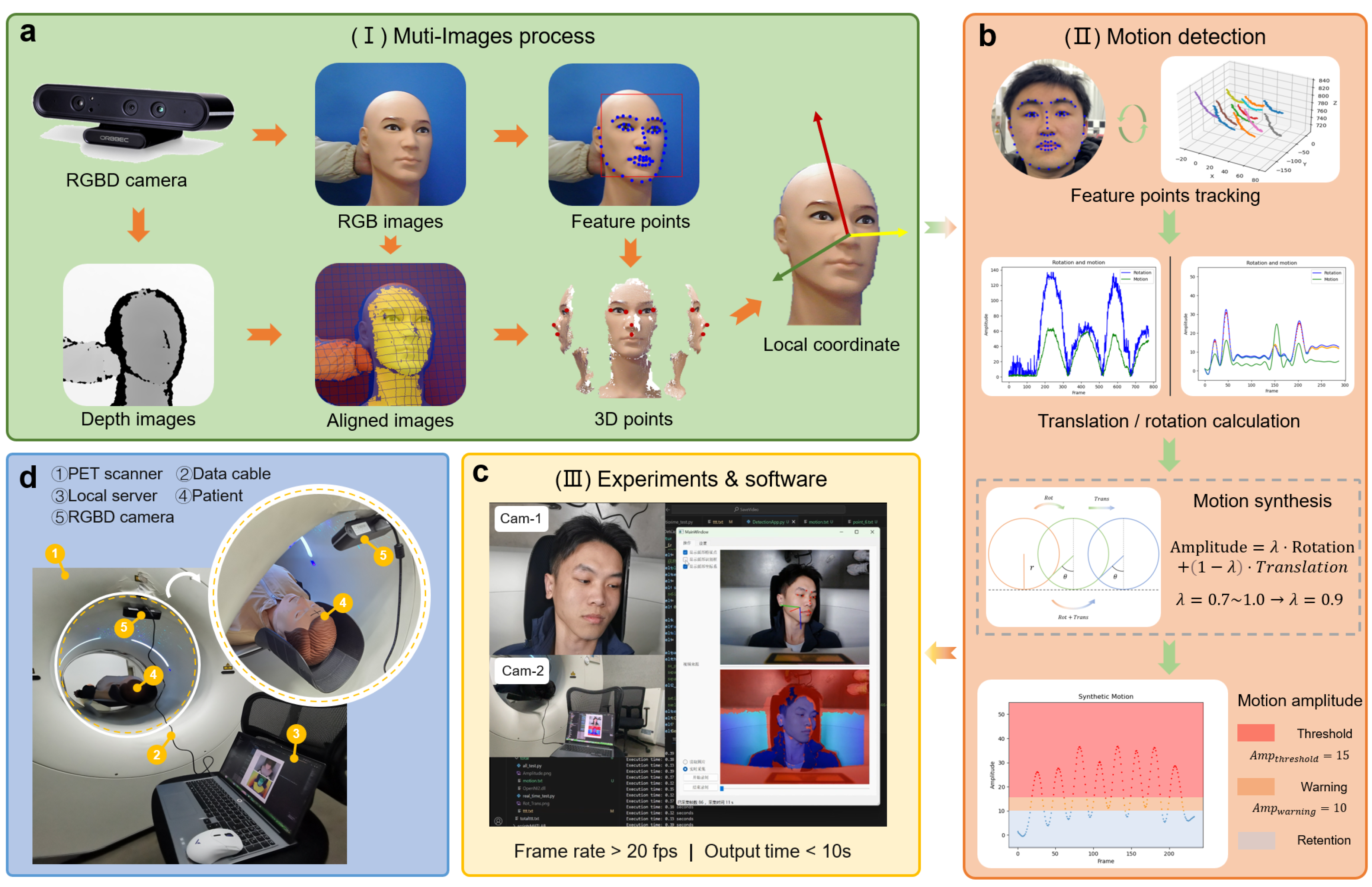
Figure 2.
Camera Calibration Interface. (a) Checkerboard for calibration (green circles: detected points, orange circle: pattern origin, red dots: reprojected points). (b)Reprojection error of checkerboard images (total of 20 images). (c)Images of checkerboard from different perspectives (total of 20 images).
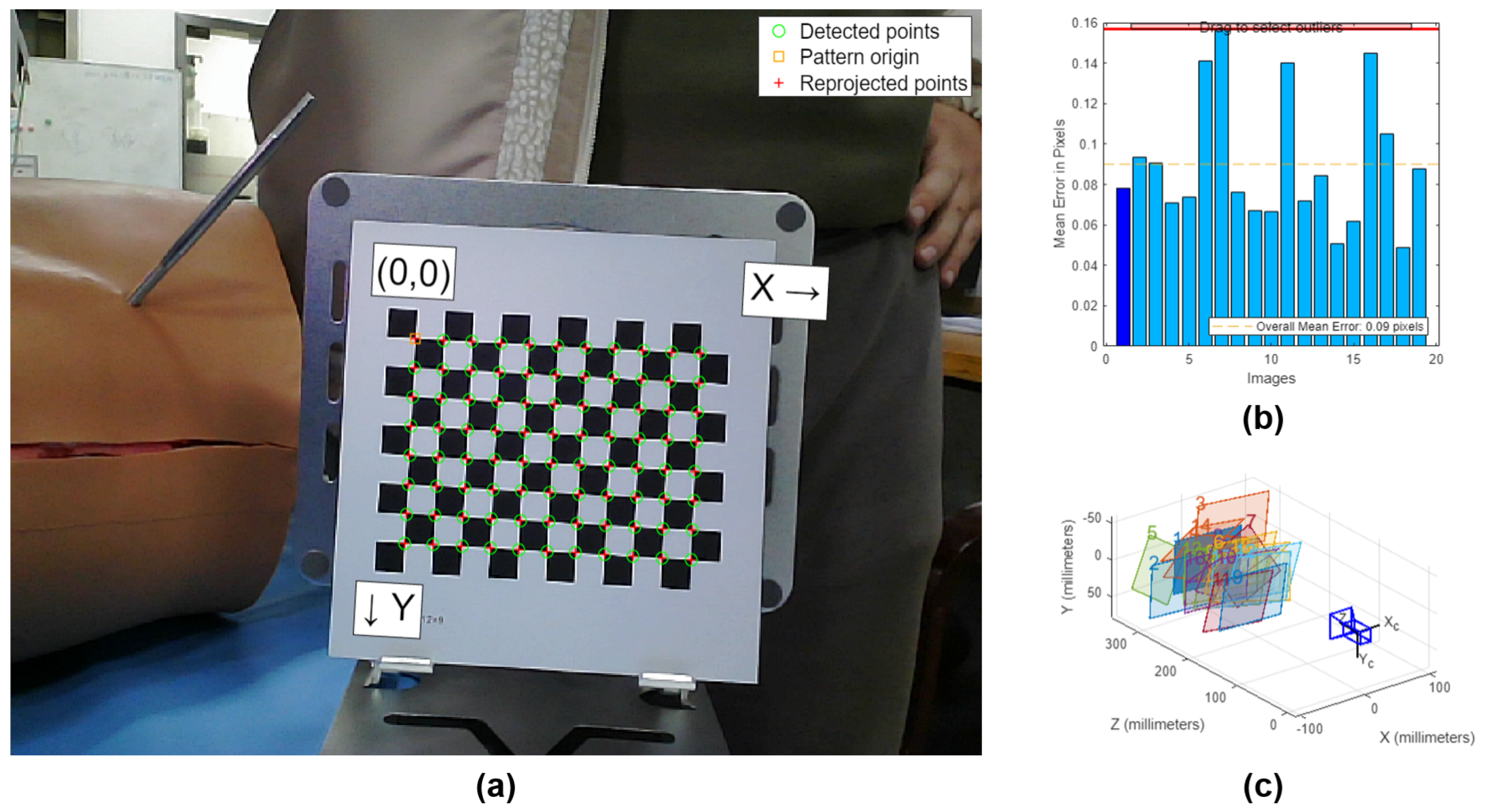
Figure 3.
Recognition effect of 68 feature points. (a) Standard diagram of 68 points. (b) Recognition effect on volunteer(68 blue dots: feature points; 8 red dots and 4 yellow stars: points used for pose calculation; 4 yellow stars: points used to describe the derivation of the formulas in subSection 3.4).
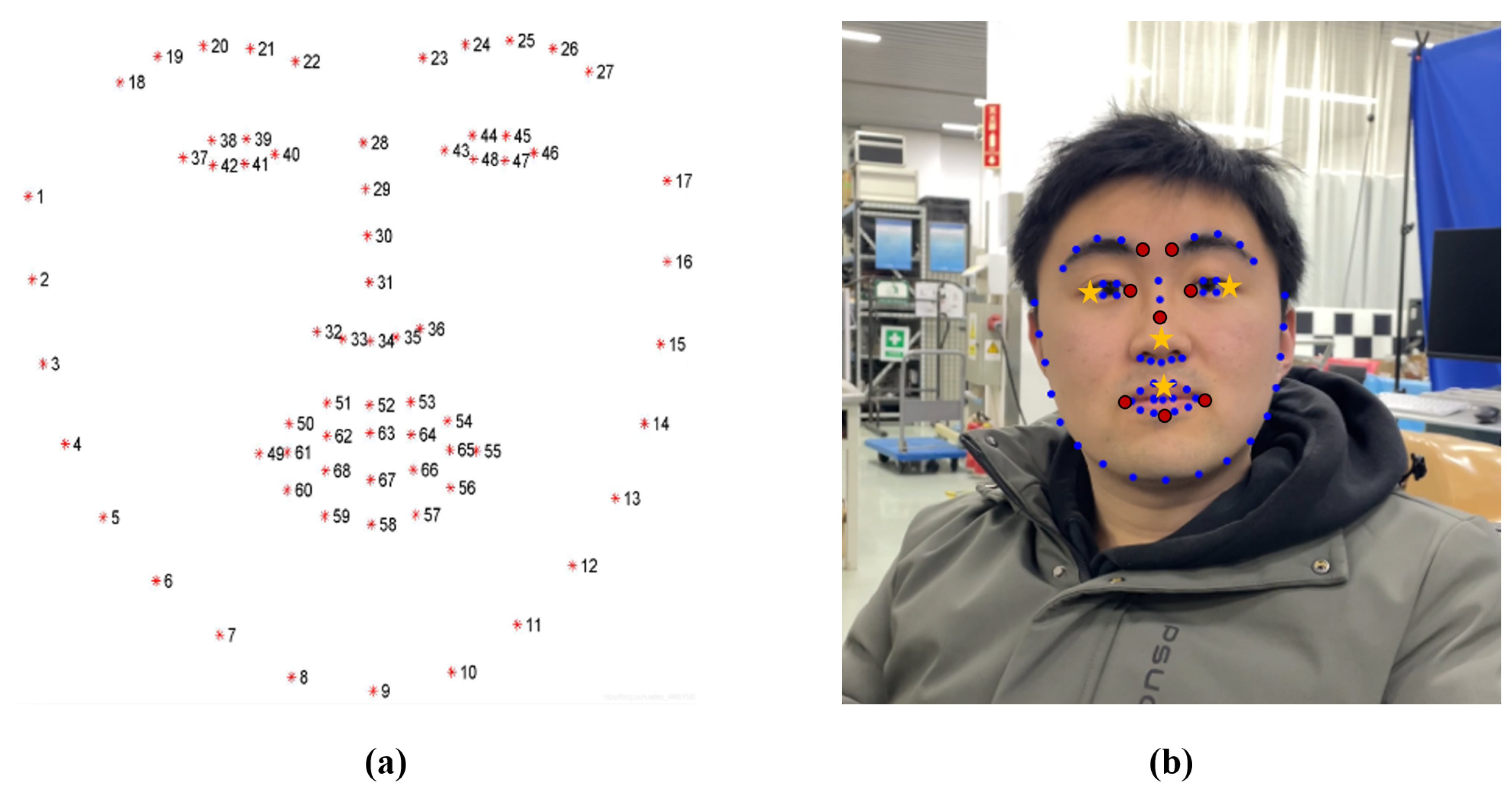
Figure 4.
The registration of depth images and RGB images. (a) Images before registration. (b)Images after registration.
Figure 4.
The registration of depth images and RGB images. (a) Images before registration. (b)Images after registration.
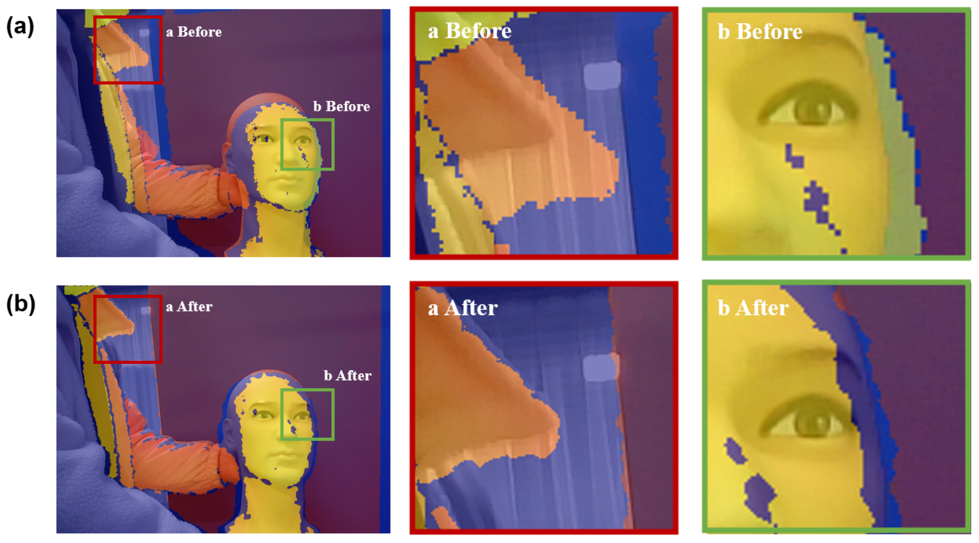
Figure 5.
Interactive software. (a)Software Design Architecture. (b)Main Interface.
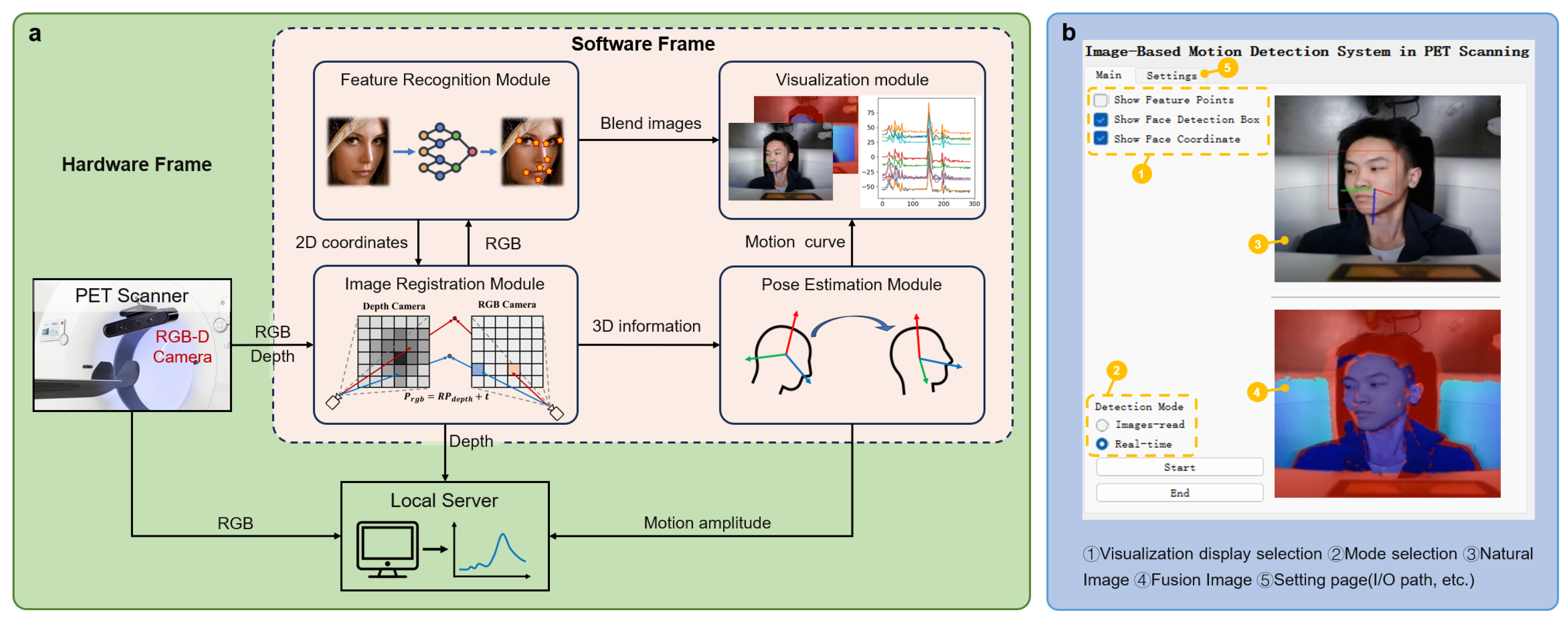
Figure 6.
Dataset composition and collection environment. (a) Phantom dataset collection environment. (b) Volunteer Dataset Collection Environment.
Figure 6.
Dataset composition and collection environment. (a) Phantom dataset collection environment. (b) Volunteer Dataset Collection Environment.

Figure 7.
The geometric significance of the "Amplitude" in the two-dimensional case. : displacement caused by rotation; : displacement caused by translation; : Weighting factor.
Figure 7.
The geometric significance of the "Amplitude" in the two-dimensional case. : displacement caused by rotation; : displacement caused by translation; : Weighting factor.
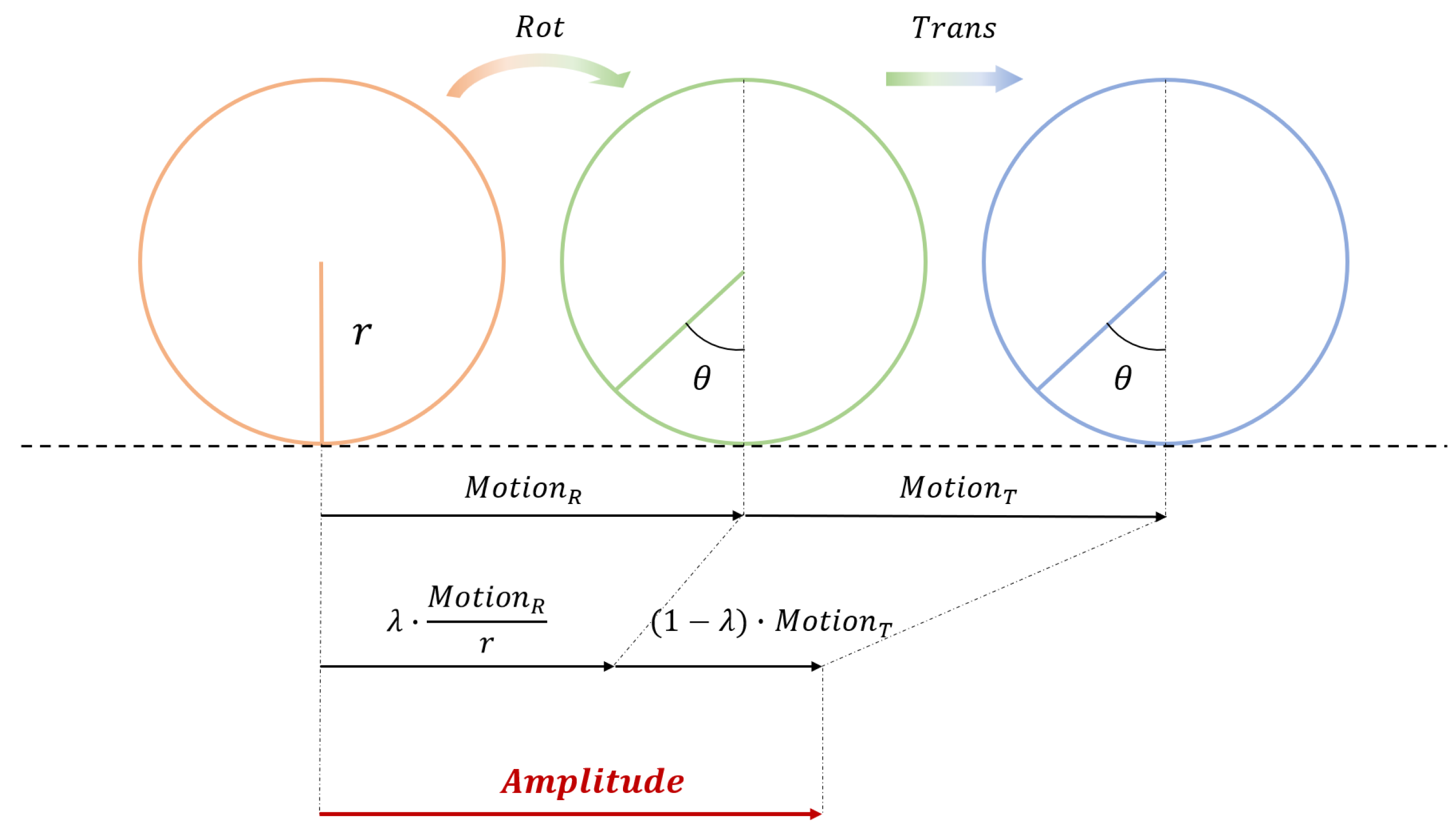
Figure 8.
Motion analysis of pitch movement. (a)The spatial position of 12 feature points. (b)The decomposition and estimation of translation. (c)The decomposition and estimation of rotation. (d)The estimation of translational amplitude and rotational amplitude. (e)The estimation of exercise intensity amplitude.
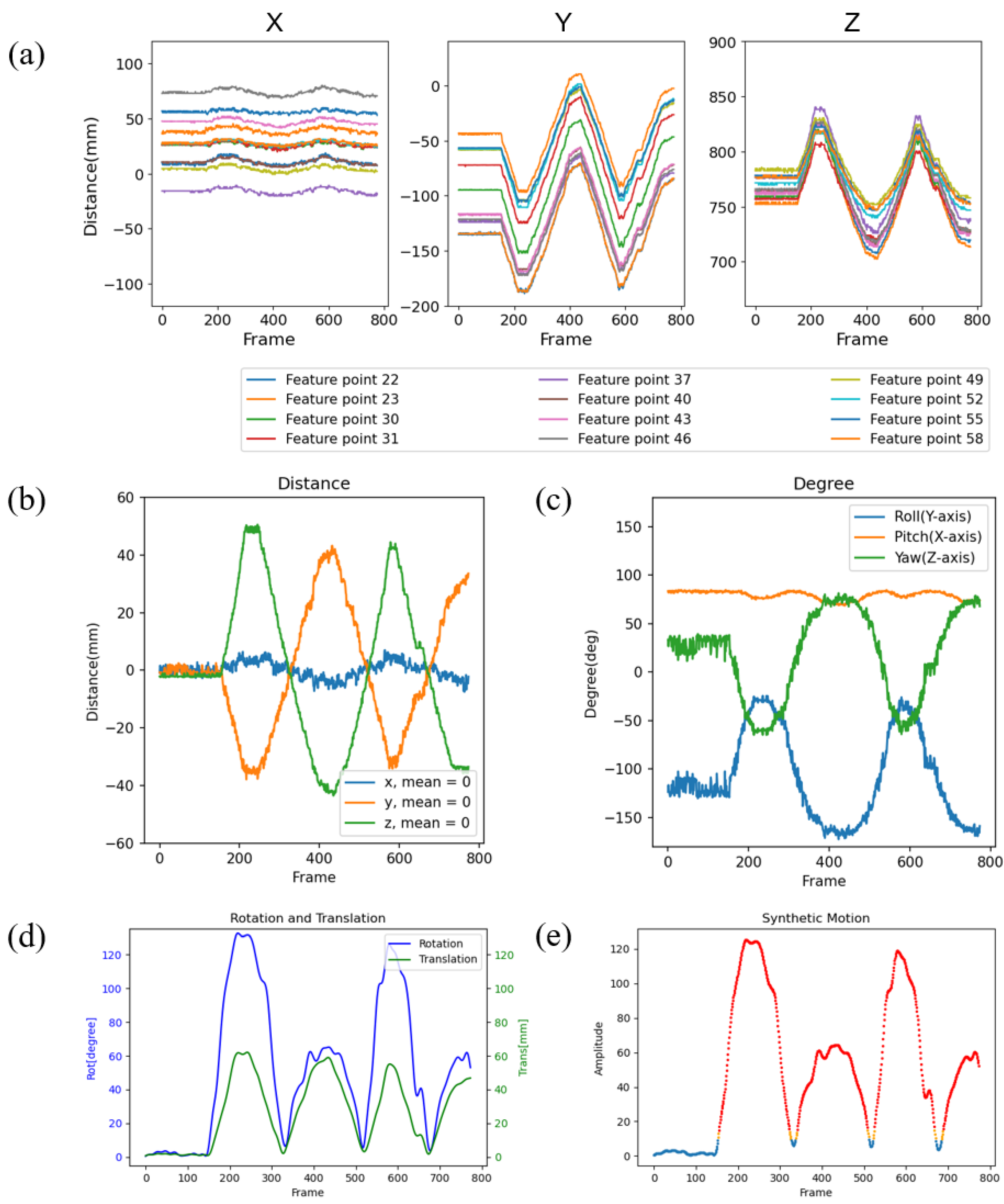
Figure 9.
Spatial position tracking of 12 feature motion points for different motions.
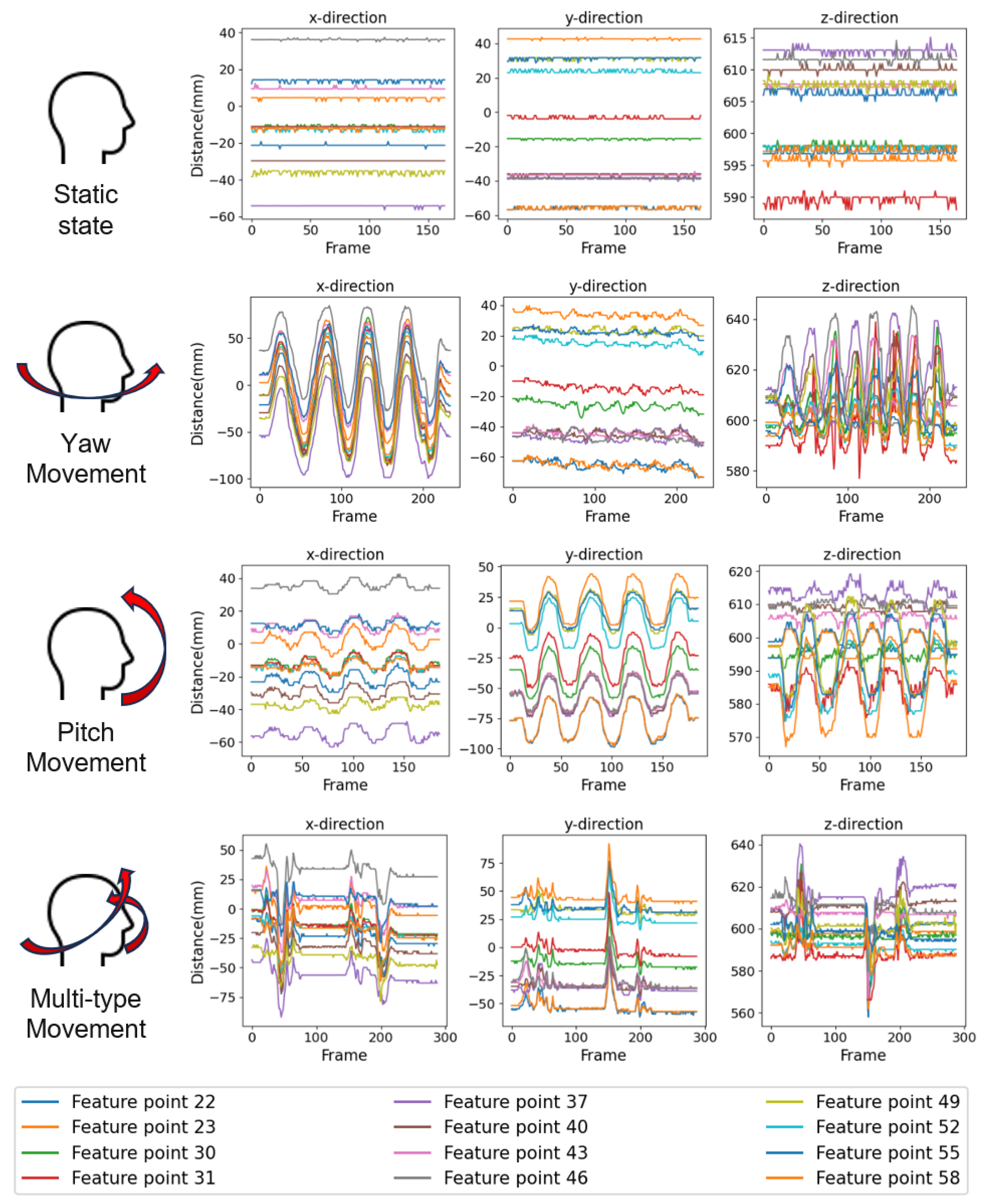
Figure 10.
Motion Amplitude Analysis of Volunteer Experiments. (a) Static state. (b) Yaw movement. (c) Pitch movement. (d) Multi-type movement.
Figure 10.
Motion Amplitude Analysis of Volunteer Experiments. (a) Static state. (b) Yaw movement. (c) Pitch movement. (d) Multi-type movement.
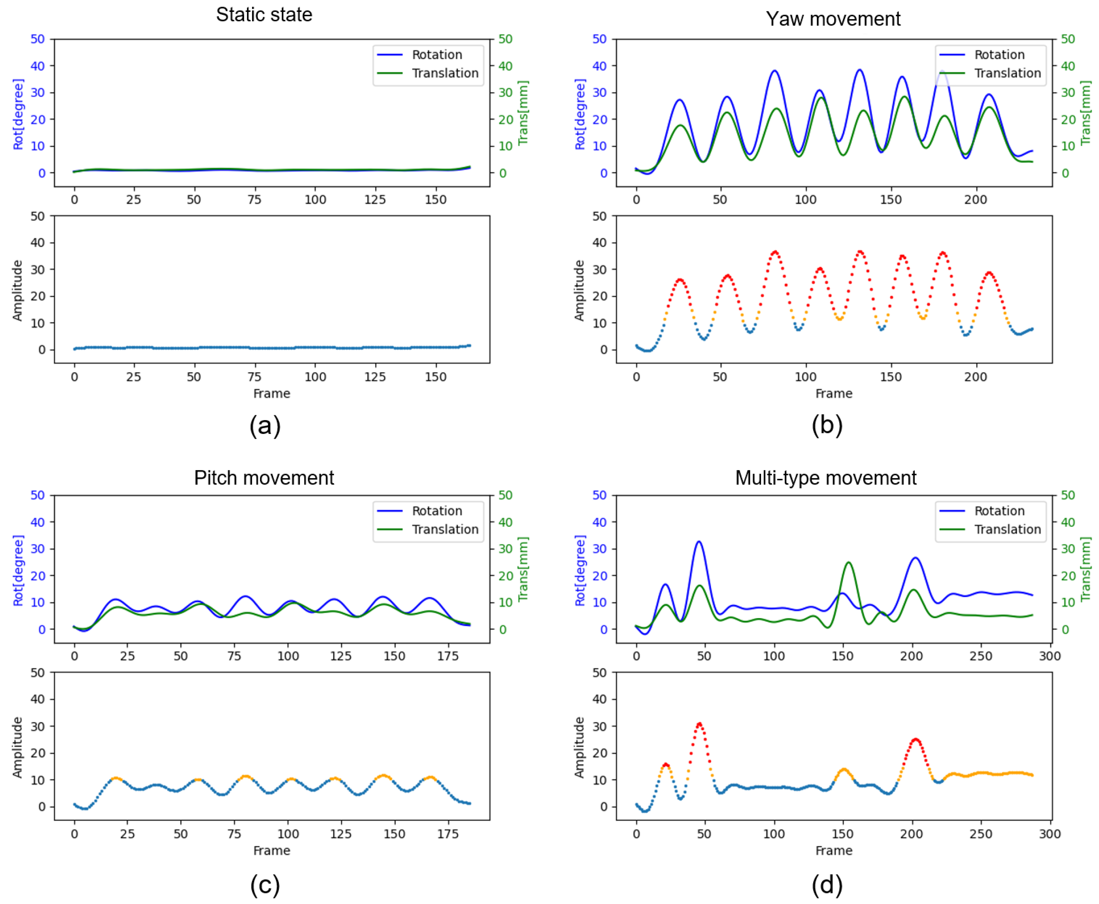

Table 1.
The time consumption of each module in the system.
| System Mode | Module | Mean (ms) | Standard Deviation (ms) |
|---|---|---|---|
| Real-time Mode | Image Acquisition Module | 21.3082 | 6.6335 |
| Depth Registration Module | 32.0709 | 2.0099 | |
| Feature Point Recognition Module | 0.0171 | 0.0074 | |
| Pose Calculation Module | 0.0274 | 0.0177 | |
| Total Time | 53.4236 | 6.9313 | |
| Image-read Mode | Total Time | 35.1104 | 3.0520 |
Disclaimer/Publisher’s Note: The statements, opinions and data contained in all publications are solely those of the individual author(s) and contributor(s) and not of MDPI and/or the editor(s). MDPI and/or the editor(s) disclaim responsibility for any injury to people or property resulting from any ideas, methods, instructions or products referred to in the content. |
© 2025 by the authors. Licensee MDPI, Basel, Switzerland. This article is an open access article distributed under the terms and conditions of the Creative Commons Attribution (CC BY) license (http://creativecommons.org/licenses/by/4.0/).
Copyright: This open access article is published under a Creative Commons CC BY 4.0 license, which permit the free download, distribution, and reuse, provided that the author and preprint are cited in any reuse.


