
Submitted:
29 April 2024
Posted:
30 April 2024
You are already at the latest version
Abstract
In the last decades we have experienced great social, cultural, and educational changes, spending more time performing tasks in near vision and less hours in outdoor activities, having more overexposure to digital screens, especially the youngest and increasingly from younger ages. It is common to see cases when performing tasks in near vision the posture or position of the head is not adequate, especially the youngest, being essential to have a correct posture of the head to avoid visual, muscular, or articular problems. We present a procedure to try to control the correct position of the head in real time when performing close-up activities. The aim is to detect the inclination of the head and to know if a bad position is adopted due to a visual problem or simply to inadequate visio-postural habits, warning us of the postural anomaly to correct it.
Keywords:
Accommodative anomalies
; Binocular anomalies
; Visio-postural control
; Eyetracking
; Image processing software
; Algorithm
; Artificial vision.
Introduction
In recent years, technological advances have resulted in overexposure of our eyes to digital screens, regardless of age, social class, or geographical area, and it is becoming increasingly common to see children at early ages with a digital device in their hands [1]. In addition to the time they devote to their education, there is an increase in the number of ours spent in front of screens and a decrease in the number of hours devoted to outdoor activities hence the importance of good visual ergonomics when performing near vision activities.
This overexposure to near vision activities with an incorrect head posture can cause the appearance of visual problems or it can be due to compensation for an undiagnosed [2,3] and therefore, uncorrected visual problems, which can lead to other muscular and joint dysfunctions.
We see cases of children and adolescents that when they are in front of a screen of a digital device, the position of their head is not correct, tilting their head to the left or to the right generating a decrease in the distance between pupils (IPD) with respect to the horizontal plane. This decrease in IPD results in a decrease in stereo acuity, which is greater when the tilt angle increases, and can affect school performance [4].
Sometimes this torsion of the head or neck (torticollis) can arise due to non-ocular conditions [5] (musculoskeletal) or for ocular reasons, due to compensatory positioning usually to maintain binocularity and/or optimize visual acuity [6], due to a clinical condition caused by paresis of the ocular muscles, nystagmus, or torticollis of muscular origin [7].
Good visual ergonomics is fundamental, especially in the youngest patients, so being able to control their visual-postural posture is essential to be able to correct postural imbalances that can lead to muscular problems [8,9], or to diagnose a visual problem associated with inadequate posture [10].
There are devices developed to quantify head tilt, some use head-mounted motion trackers [11] and others integrated gyroscopes [12], or like the one created by our team in 2016, which has two LEDs at the ends of the optical mount and is based on the same principle that we will use in this application [13].
What has evolved the most are the applications focused on digital devices, being the tools that today and in the future, we will use the most both for leisure and in our work environment. There are applications that use an eyetracking system [14] which tracks the subject's eyes, either in mobile applications or in other digital devices, but none with the aim of measuring the inclination of the head. We do know of other applications that use face recognition software to measure head turn [15].
Today we are not aware of any device or application that measures head tilt in real time when the subject is performing an activity in near vision using this system. Most digital devices already have a built-in CCD sensor, which has led to the proposal of this project. Which through a monitoring of our eyes can make a visio-postural control of the subject, so we can avoid or detect possible visual complications in the future achieving best visual performance.
Materials and Methods
2.1. Design and Description of the Algorithm for Detection.
For the design and creation of the new method we need devices that use a CCD detector through which we obtain images in real time.
We developed an algorithm based on image processing techniques [16,17] that allows us to detect and track the subject's pupils in real time through the CCD detector.
The calibration will consist of relating the different interpupillary distances (IPD) of the subjects and with the different distances at which the task is performed. Once the method has been calibrated using the algorithm, we know the pupil coordinates and by means of a simple mathematical calculation we obtain the inclination of the subject's head in real time, showing the degrees of inclination on the screen of the device. Figure 1 shows the flowchart of the algorithm designed to measure head tilt.
2.1.1. Image Tracking and Pre-Processing Algorithm
We capture the first frame and proceed to detect the subject's eyes by selecting a cascade object detector, choosing in this case the Viola & Jones [18] algorithm (Figure 2).
When we have detected the eyes, we go ahead to their segmentation to detect the iris and pupils, we present the two eyes separately so that the algorithm we use will find it easier to detect them.
For the detection of the iris and pupils we choose the iris segmentation program using the Daugman integrodifferential operator [19], finding the iris and giving us the radius and coordinates of the center of the iris radii and coordinates of the iris and pupil center (Figure 3).
Once the iris is found, we go ahead to check and track it by point tracking using the Kanade-Lucas-Tomasi (KLT) feature tracking algorithm [20,21]. The points you must track are the centers of the pupils, searching for them and showing them to us in real time in frames. It is possible that as the video progresses some of the points are lost or not tracked, probably due to a variation of the illumination or loss of fixation of the subject on the text that is presented, in this case the application re-acquires the points again to be able to track them.
Once the centers of each pupil are found, we know the x and y pixel coordinates of the right and left pupil (Figure 4)
2.2. Calibration Process of the Algorithm for Head Tilt Measurement.
For tilt calibration we created a template with a computer design program with 9 interpupillary distances with which we represented almost all subjects [22] IPD (Figure 5) varying between 45 and 85 mm, checked with a graduated ruler with a margin of error of ±1mm.
The detection of the circles is done with the Hough transform algorithm [23], being a technique for shape detection by edge localization, it detects the circle and the coordinates of its center.
To perform the calibration and measurement tests we used a Huawei Matebook laptop computer model MRC-W60 (Figure 6a) which has an integrated camera with which we went ahead to make the video choosing a resolution of 1280 × 720 pixel, an image frequency of 30 frames per second and a refresh rate of 50 Hz.
The template is fixed to a goniometer with a margin of error of 0, 1º, which allows us to tilt and quantify the degrees of inclination of the points with respect to the computer camera.
The system will be leveled with a Fisco model EN 17 inclinometer with a measurement accuracy of 0˚/90˚ = +/-0.05˚ 1˚- 89˚ = +/-0.2˚, at 0º for both the laptop and the template.
The template will be placed at different distances which will be measured with a Bosch GLM40 laser rangefinder with a margin of error of ±1.5mm, and at each distance we will measure different inclinations, taking frames of all the measurements for processing by the mathematical program.
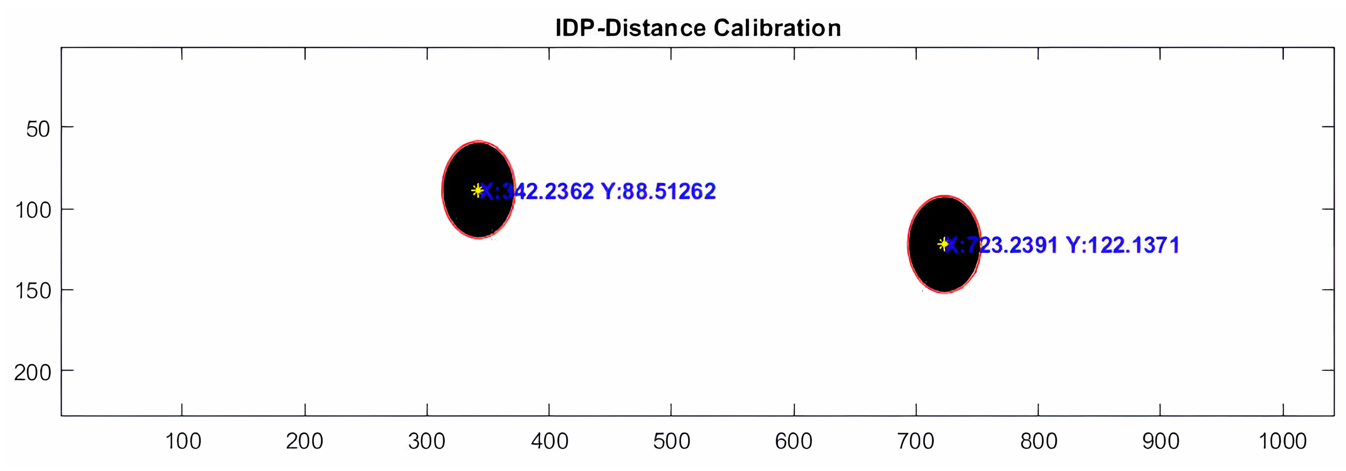
The goniometer on which the template is fixed (Figure 6b) gives us the degrees of rotation, right in positive value and left in negative value, which we will relate to the separation of the pupillary centers in the vertical axis.
All calibration measurements were performed in a light environment between 200 and 400 lux.
To measure the light level, we used an RS Pro ILM 1337 lux meter with a resolution of 0.01 lux and an accuracy of ± 3% + 5dgt.
2.2.1. Adjustment by Linear Regression for the Calibration of the Inclination
We know the coordinates on the vertical (y) axis (Figure 7), so we only need to relate the degrees of tilt of the template to the vertical pixel separation of the two images (y2-y1). Where the result can be negative or positive, depending on whether the subject tilts the head to the left or to the right.
Figure 8a shows the degrees measured by a goniometer (Y axis) and the pixel difference between the centers of the two circles (X axis).
In this case the equation that best relates these variables is that of a straight line, so a linear regression [24] adjustment will be adopted which estimates the values of the X axis (dependent variable) from the values of the Y axis (independent variable) obtaining the following predictive equation:
The correlation coefficient R= 0.998 is close to 1, specifically 99.98% of the deviation of the Y variable by respect to its mean. It is explained by the adjusted linear regression model. Finding that this regression model is statistically significant with a p-value= 1.25 e-09, so we can ensure that the linear model is adequate to describe the relationship that exists between these variables and predict the data.
Figure 8.
(a). Linear adjustment to relate the degrees and the pixel difference of the Y axis. (b) Error induced by the algorithm in the measurement of template inclination at different distances once calibrated for an IPD of 65 mm.
Figure 8.
(a). Linear adjustment to relate the degrees and the pixel difference of the Y axis. (b) Error induced by the algorithm in the measurement of template inclination at different distances once calibrated for an IPD of 65 mm.
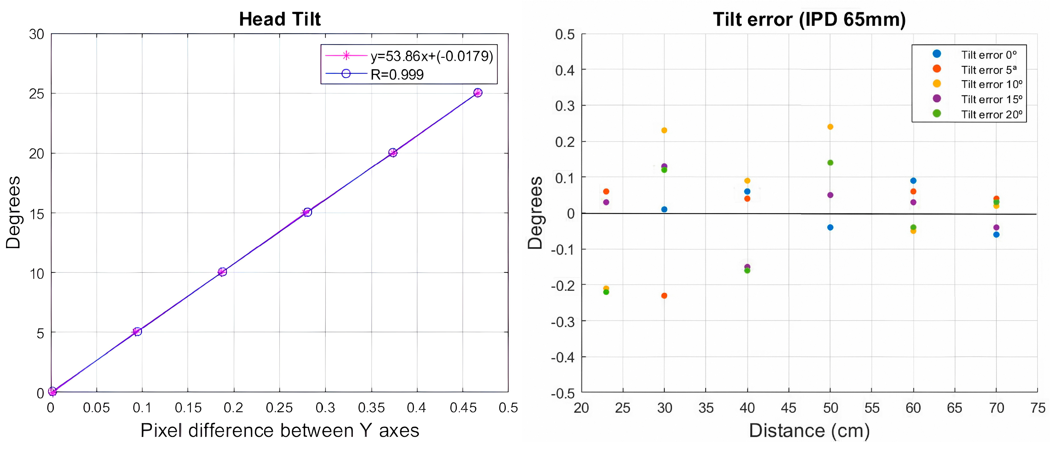
Once the system was calibrated, five measurements were made at different inclinations, increasing by 5º degrees at each measurement, until reaching 20º degrees. This process was performed at six different distances, starting from 23.5 cm, increasing the distance up to 70 cm. This process was repeated at different interpupillary distances, with the average measured error being less than 0.30º degrees of inclination (Figure 8b).
2.3. Measurement of Head Tilt in Real Time Evaluated on Subjects.
Once calibration of the system is complete, it is ready to evaluate its performance on subjects by tracking head tilt in real time.
The system was evaluated on seven subjects ranging in age from 12 to 55 years. Two of the subjects, one adult and one child were wearing their usual optical correction in their glasses at the time of testing. The test was performed on a test bench where the subject rested his head on a chin rest (Figure 7a), while being shown a text on the laptop computer. The ambient light environment in which the tests were performed is 300±50 lux.
The video was recorded with the computer camera with a resolution of 720 pixel, an aspect ratio of 16:9 and a speed of 30fps.
Figure 9.
a). Volunteer with his head resting on a chin rest for the start of the measurement tests. (b) Laptop with inclination controlled by the inclinometer to conduct the tests.
Figure 9.
a). Volunteer with his head resting on a chin rest for the start of the measurement tests. (b) Laptop with inclination controlled by the inclinometer to conduct the tests.
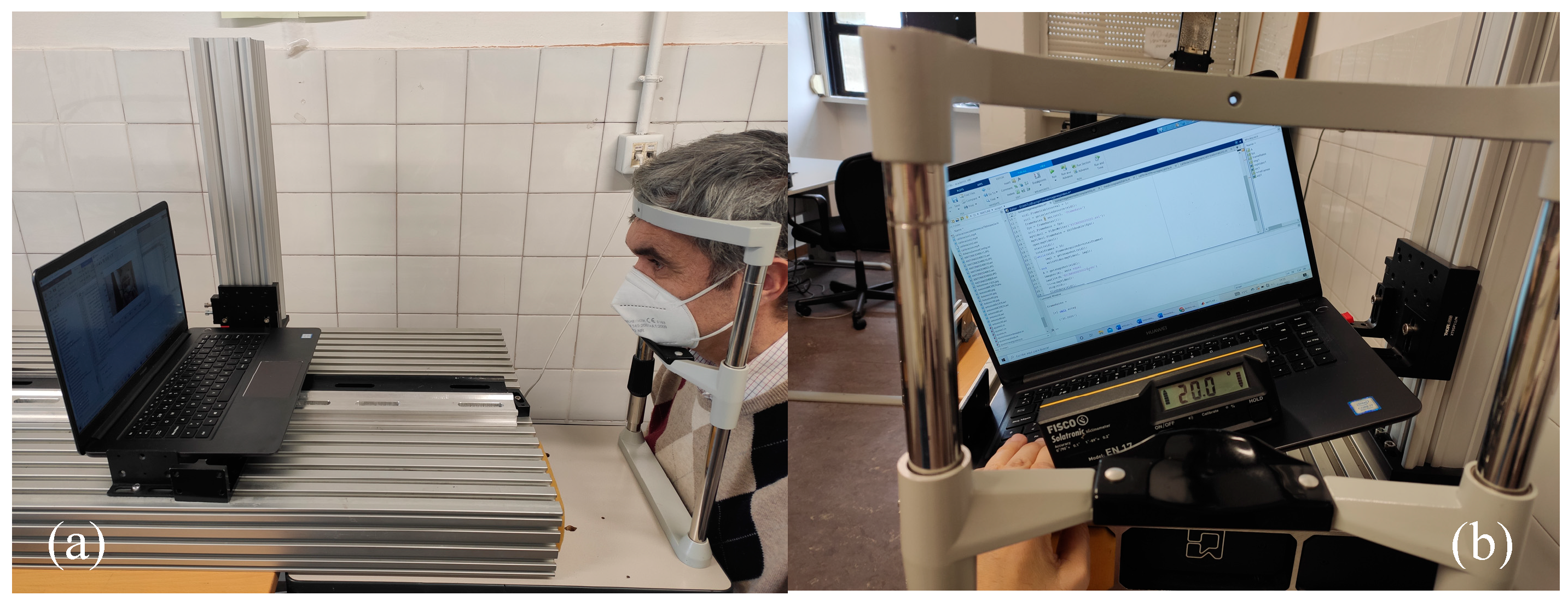
Each subject was videotaped at different distances and at each distance at three different inclinations of the laptop computer (Figure 7b). Between 40 and 50 images were obtained from each video, obtaining the mean head tilt at each distance.
The first measurement will be taken at 0º inclination of the laptop, this will be our starting point since the subjects do not have their eyes perfectly aligned in the horizontal plane. Later measurements will subtract the result obtained at the 0º position of the computer from the rest of the tilt measurements.
Results
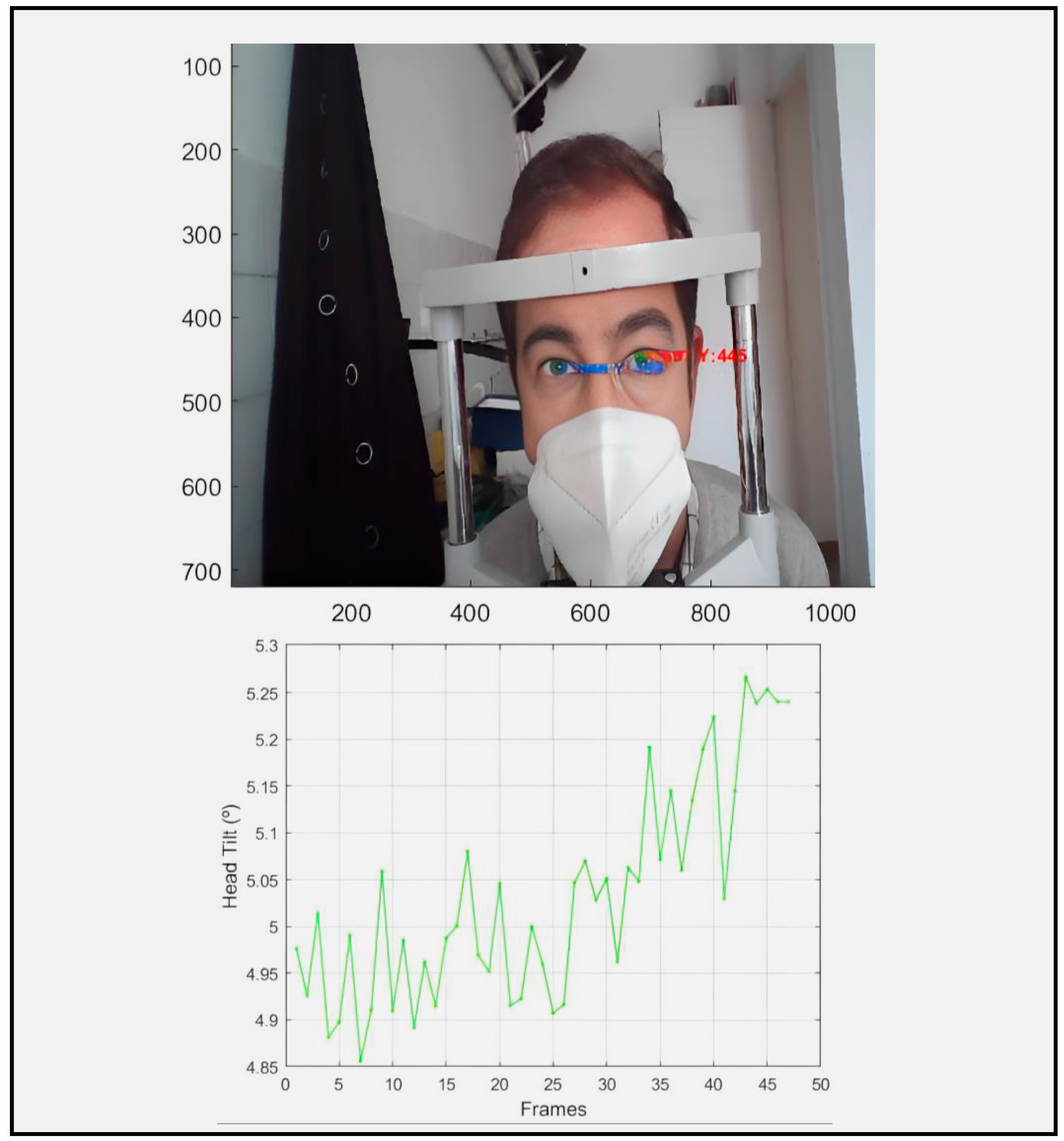
The system tracks the pupils by quantifying in real time the inclination of the head in degrees with respect to the CCD receiver device (Figure 8).
Figure 10.
Representation of eye tracking of the subject where we are informed in real time of the turn of the head (5º).
Figure 10.
Representation of eye tracking of the subject where we are informed in real time of the turn of the head (5º).
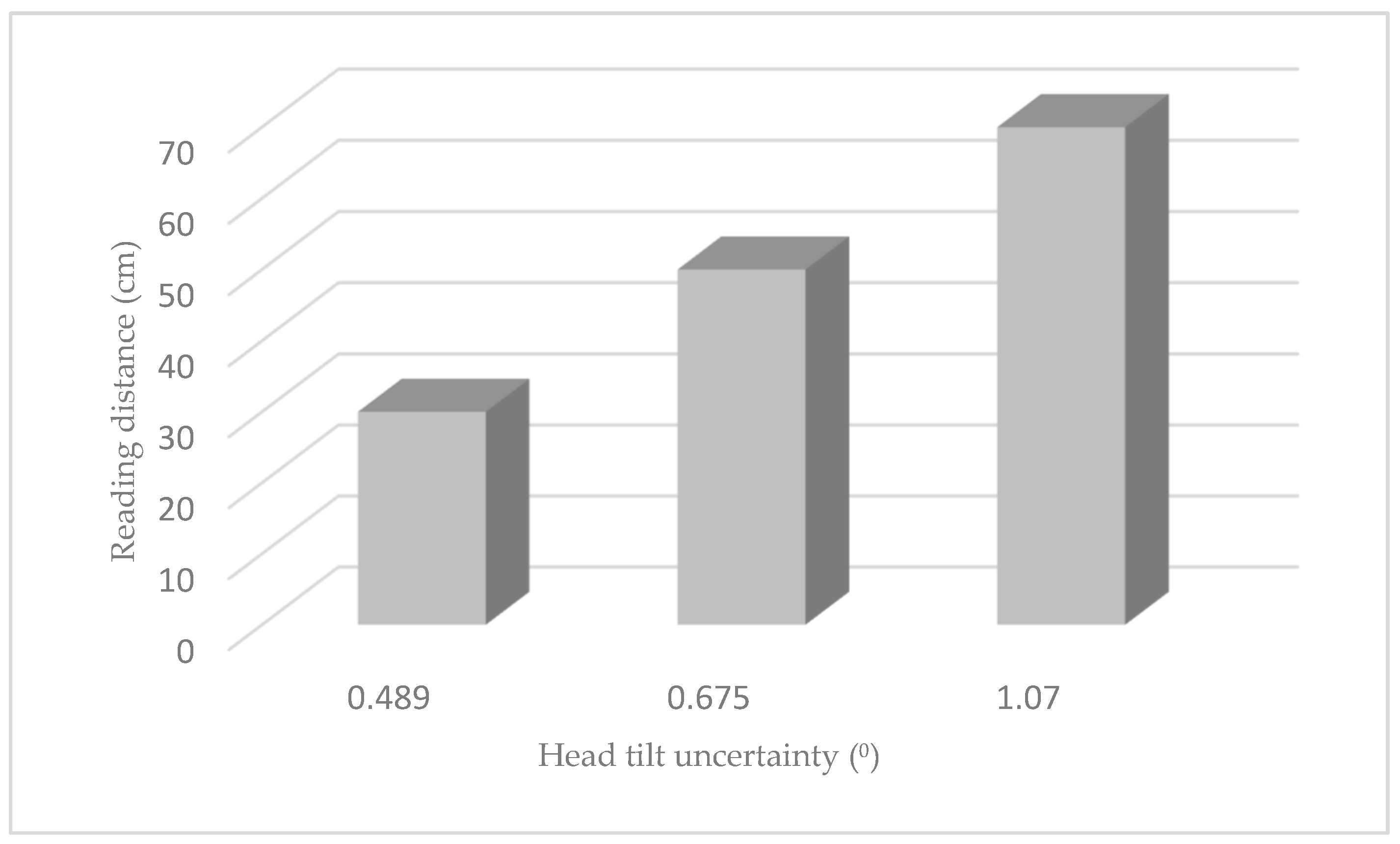
The values represented in Figure 9 correspond to the different head tilt measurements performed on seven subjects. Each subject's head tilt was tracked through a video for each tilt level, obtaining the mean head tilt of each video. The process was performed at three distances 30, 50 and 70 cm.
Figure 11.
Tilt error evaluated on multiple people in real time at different distances.
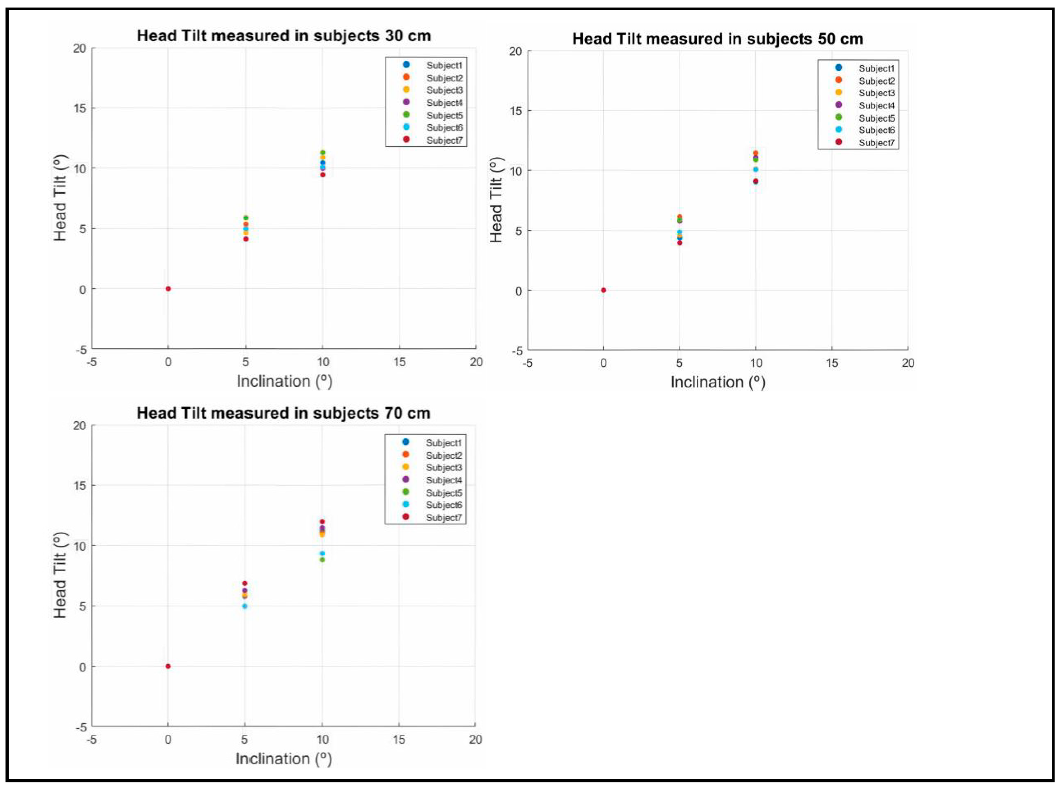
For the 30 cm distance we obtained an absolute error of 0.489 degrees for the seven subjects measured, 0.675 degrees for the 50 cm distance and 1.070 degrees for the 70 cm distance.
Discussion
We can observe especially in children and adolescents that when they are in front of a screen their head positioning is not correct, tilting their head to the left or to the right, which can cause muscular problems5 in the future or due to compensation for a visual anomaly10.
Quantifying the head tilt of individuals in the clinical setting is not a commonly performed test, determining the magnitude of the tilt by observation of the patient's head, and there is a surprisingly high degree of variability among pediatric ophthalmologists in defining standard gaze positions [25]. In some cases, the estimation of certain head tilt positions is quite inaccurate giving an average error of 10 ± 8 degrees [26].
Several devices have been developed to monitor head tilt, some using analog methods such as that of Hald et al. based on head-mounted motion trackers11 where repeatability limits of ninety-five percent yielded ranges of less than 10 degrees for all abnormal head postures. Others such as Al-Yassary et al. carry an electronic device based on an inertial measurement unit that is attached to the subject's head consisting of gyroscopes and accelerometers12, reporting the validity and reliability of the device. Unfortunately, these methods require additional devices to quantify head tilt and are not applicable in clinical practice for real-time quantification.
Recently, we found devices or methods that use facial recognition software to measure head tilt, such as the one proposed by Baek et al. [27] which uses an infrared emitter and a facial recognition algorithm or the one proposed by Thomas et al. [15] very similar to our system since it runs on a standard PC with Windows environment and for image processing uses any standard webcam, not requiring additional devices. The error increases with more extreme head posture, achieving a mean absolute error of less than 5° in the operating range of ±50° of head tilt, allowing a useful quantification of the tilt in real time.
Compared to other techniques, our system does not require any additional elements, it only needs a hardware with a CCD detector and a software that can be unloaded. Most digital devices already have this type of detector hence this system has been proposed.
4.1. Device Calibration.
Calibration of the device was performed to make the system functional for all subjects with different interpupillary distances, ranging from 45 - 85 mm and for different reading distances ranging from 23.5 cm to 70 cm. For the detection of the circles of the template we chose a program based on the recognition of the edges of the figure, the algorithm used is the Hough transform and we could com-prove that it detected the circles in a quite wide range of light environments, choosing for the calibration a light environment between 200 and 400 lux, which is the light environment we found in the laboratory.
Its high correlation 99.98% to describe the relationship between these variables and the prediction of the data, ensure a good agreement between the measurement made by the system and the measurements made by the laser rangefinder.
The error produced in the calibration was not related to the different distances between the circles (DIP) nor to the distance from the CCD detector to the circle template, so it did not influence the measurement of the tilt angle, obtaining an error margin of 0.30º of tilt, this error is supposed to be produced by human errors when adjusting the system and instrumental errors.
4.2. Measurement in Subjects
The results showed that in most of the variables very good absolute and relative reliability values were found, measuring head inclination with an accuracy of less than 1° within the range of distances between 30 and 70 cm, this being the range of distances most used by users of both mobile phones [28] and computers [29].
The absolute errors achieved by our system in the validation study compared with other systems or published methods are very good. The average error measured in the subjects is 0.744°, with the error increasing as we increase the distance at which the text is presented (Figure 10), this is because the pupil centers detected by the algorithm are not as accurate as at shorter distances, due to the decrease in pixels in the iris and pupil outline.
Figure 12.
Absolute uncertainty in the measurement of head tilt at different distances.
No significant differences were found in the measurement of tilt between the different interpupillary distances of the subjects. The algorithm had no problems in detecting the eyes of the subjects in different light environments and between subjects who wore optical correction (glasses) and those who did not.
The light environment of the laboratory where the measurements were taken is 300±50 lux, and the system was adjusted to quantify in real time the position of the subject's head (degrees) with a high spatiotemporal resolution, detecting the position of the subject 10 times per second. It alerts us when the position of the head exceeds a previously defined inclination by means of a text message and an audio warning.
To our knowledge, we are not aware of any device or application that measures head tilt in real time by monitoring the eyes when the subject is doing an activity in front of a digital device.
Considering its high performance, ease of use and low cost, we believe that this system has great potential to control head tilt and thus be able to correct and avoid visual complications in the future, making it a prevention and treatment system to achieve optimal visual performance.
Conclusions
To address the postural problem of children and adults in front of visualization screens, we propose a system based on an eye-tracking algorithm using image processing to quantify the head tilt and correct it. Experimental results show that the system works with different IPD of the subjects and at different distances, measuring head tilt with an absolute error of 0, 744º at a speed of 10 fps.
The system was tested in different lighting environments and on different subjects, with optical correction (glasses) and others without glasses, the algorithm of the system has perfectly detected their pupils, fulfilling the purpose of measuring the inclination of the head of the subjects.
The evaluated results have been positive, making it a considerably inexpensive and easily affordable system for all users, being the first application capable of measuring the head tilt of the subject at their working or reading distance in real time by tracking their eyes.
In the next stage of research, we will try to improve this algorithm so that it can also measure the distance to the display screens without the need of any additional detector, only the CCD detector, making it a more complete monitoring system when we are in front of a display screen.
Author Contributions
Principal author, Miguel Ángel Tomé de la Torre. Conceptualization, Miguel Ángel Tomé de la Torre and Antonio Álvarez Fernández-Balbuena; methodology, Miguel Ángel Tomé de la Torre; software, Miguel Ángel Tomé de la Torre; validation, Miguel Ángel Tomé de la Torre, Antonio Álvarez Fernández-Balbuena, Ricardo Bernardez Vilaboa and Daniel Vázquez Molini; formal analysis, Antonio Álvarez Fernández-Balbuena; investigation, Miguel Ángel Tomé de la Torre; data curation, Miguel Ángel Tomé de la Torre; writing—original draft preparation, Miguel Ángel Tomé de la Torre; writing—review and editing, Miguel Ángel Tomé de la Torre; visualization, Daniel Vázquez Molini; supervision, Antonio Álvarez Fernández-Balbuena and Ricardo Bernardez Vilaboa. All authors have read and agreed to the published version of the manuscript.
Funding
Granted by Ministry of Science, Innovation and Universities, SPAIN. Project: "Advanced optical technologies applied to the analysis and restoration of historical tapestries." PID2022-138061OB-I00. Proyectos Generación del Conocimiento 2022.
Informed Consent Statement
Informed consent was obtained from all subjects involved in the study.
Data Availability
The data used in this study are available upon request to the corresponding author.
Conflicts of Interest
The authors declare that there are no conflicts of interest regarding the publication of this paper.
References
- Moreno Villares, J.M.; Galiano Segovia, M.J. Screen-time: A new stakeholder in children and adolescent health. Nutr Hosp. 2019, 36, 1235–1236. [Google Scholar] [CrossRef] [PubMed]
- Nucci, P.; Kushner, B.J.; Serafino, M.; Orzalesi, N. A multi-disciplinary study of the ocular, orthopedic, and neurologic causes of abnormal head postures in children. Am J Ophthalmol. 2005, 140, 65–68. [Google Scholar] [CrossRef] [PubMed]
- Bradnam, L.; Chen, C.S.; Callahan, R.; Hoppe, S.; Rosenich, E.; Loetscher, T. Visual compensation in cervical dystonia. J Clin Exp Neuropsychol. 2019, 41, 769–774. [Google Scholar] [CrossRef] [PubMed]
- Lam, D.Y.; Cheng, T.L.; Kirschen, D.G.; Laby, D.M. Effects of head tilt on stereopsis. Binocul Vis Strabismus Q. 2008, 23, 95–104. [Google Scholar] [PubMed]
- Shapiro, I.J. Relation between vertical facial asymmetry and postural changes of the spine and ancillary muscles. Optom Vis Sci. 1994, 71, 529–538. [Google Scholar] [CrossRef] [PubMed]
- Rubin, S.E.; Wagner, R.S. Ocular torticollis. Surv Ophthalmol. 1986, 30, 366–376. [Google Scholar] [CrossRef] [PubMed]
- Williams, C.R.; O'Flynn, E.; Clarke, N.M.; Morris, R.J. Torticollis secondary to ocular pathology. J Bone Joint Surg Br. 1996, 78, 620–624. [Google Scholar] [CrossRef] [PubMed]
- Szczygieł, E.; Fudacz, N.; Golec, J.; Golec, E. The impact of the position of the head on the functioning of the human body: A systematic review. Int J Occup Med Environ Health. 2020, 33, 559–568. [Google Scholar] [CrossRef] [PubMed]
- Chiang, H.Y.; Liu, C.H. Exploration of the associations of touch-screen tablet computer usage and musculoskeletal discomfort. 2016, 53, 917–925. [Google Scholar] [CrossRef] [PubMed]
- Nucci, P.; Curiel, B.; Lembo, A.; Serafino, M. Anomalous head posture related to visual problems. Int Ophthalmol. 2015, 35, 241–248. [Google Scholar] [CrossRef] [PubMed]
- Hald, E.S.; Hertle, R.W.; Yang, D. Application of a digital head-posture measuring system in children. Am J Ophthalmol. 2011, 151, 66–70. [Google Scholar] [CrossRef] [PubMed]
- Al-Yassary, M.; Billiaert, K.; Antonarakis, G.S.; Kiliaridis, S. Evaluation of head posture using an inertial measurement unit. Sci Rep 2021, 11, 19911. [ScienceDirect]. [CrossRef] [PubMed]
- Tomé, M.A.; Villena, C.; Álvarez, A. Real time control device for reading distance and head tilt. Optik 2016, 127, 11918–11926. [ScienceDirect]. [CrossRef]
- Mayberry, A.; Hu, P.; Marlin, B.; Salthouse, C.; Ganesan, D. iShadow: Design of a Wearable, Real-Time Mobile Gaze Tracker. MobiSys. 2014, 2014, 82–94. [Google Scholar] [PubMed]
- Thomas, P.B.; Baltrušaitis, T.; Robinson, P.; Vivian, A.J. The Cambridge Face Tracker: Accurate, Low-Cost Measurement of Head Posture Using Computer Vision and Face Recognition Software. Transl Vis Sci Technol. 2016, 5, 8. [Google Scholar] [CrossRef] [PubMed]
- Rafael, C.G.; Richard, E.W.; Eddins, S.L. Digital image processing using matlab.2009; pp. 318–681.
- Cuevas E.J.; Zaldívar, N.D. Visión por Computador utilizando Matlab y el Toolbox de Procesamiento Digital de Imágenes.2013; pp.4-31.
- Viola, P.; Michael, J.J. Rapid Object Detection using a Boosted Cascade of Simple Features. In Proceedings of the 2001 IEEE Computer Society Conference on Computer Vision and Pattern Recognition, 2001; Volume: 1, pp. 511–518. [Researchgate].
- Sivaraman, A. Iris Segmentation Using Daugman's Integrodifferential Operator, MATLAB Central File Exchange. Retrieved June 25, 2020. [Mathworks].
- Bruce, L.; Kanade, T. An Iterative Image Registration Technique with an Application to Stereo Vision. Proceedings of the 7th International Joint Conference on Artificial Intelligence, April 1981, pp. 674–679. [Researchgate].
- Tomasi, Carlo.; Kanade, T. Detection and Tracking of Point Features. Computer Science Department, Carnegie Mellon University, April 1991. [cmu.edu].
- Neil, A. D. Variation and extrema of human interpupillary distance, Proc. SPIE 5291, Stereoscopic Displays and Virtual System XI, (21 May 2004). [Researchgate].
- https://es.mathworks.com/help/images/ref/imfindcircles.html Accessed on October 24, 2023.
- https://es.mathworks.com/help/matlab/data_analysis/linear-regression.html Accessed on October 24, 2023.
- Granet, D.B.; Ventura, R.H.; Miller-Scholte, A.; Hertle, R.W.; Capistrano, A.P. Marked variability amongst pediatric ophthalmologists in designating the diagnostic gaze position angles in ocular motility evaluations. Binocul Vis Strabismus Q. 2001, 16, 291–296. [Google Scholar] [PubMed]
- Kim, D.S.; Coats, D.K.; McCreery, K.M.; Paysse, E.A.; Wilhelmus, K.R. Accuracy of clinical estimation of abnormal head postures. Binocul Vis Strabismus Q. 2004, 19, 21–24. [Google Scholar] [PubMed]
- Oh, B.L.; Kim, J.; Hwang, J.M.; Lee, J. Validity and reliability of head posture measurement using Microsoft Kinect. Br J Ophthalmol. 2014, 98, 1560–1564, Epub 2014 Jun 11. [Google Scholar] [CrossRef] [PubMed]
- Bababekova, Y.; Rosenfield, M.; Hue, J.E.; Huang, R.R. Font size and viewing distance of handheld smart phones. Optom Vis Sci. 2011, 88, 795–797. [Google Scholar] [CrossRef] [PubMed]
- Gowrisankaran, S.; Sheedy, J.E. Computer vision syndrome: A review. 2015, 52, 303–314. [Google Scholar] [CrossRef] [PubMed]
Figure 1.
Flow chart of the System.
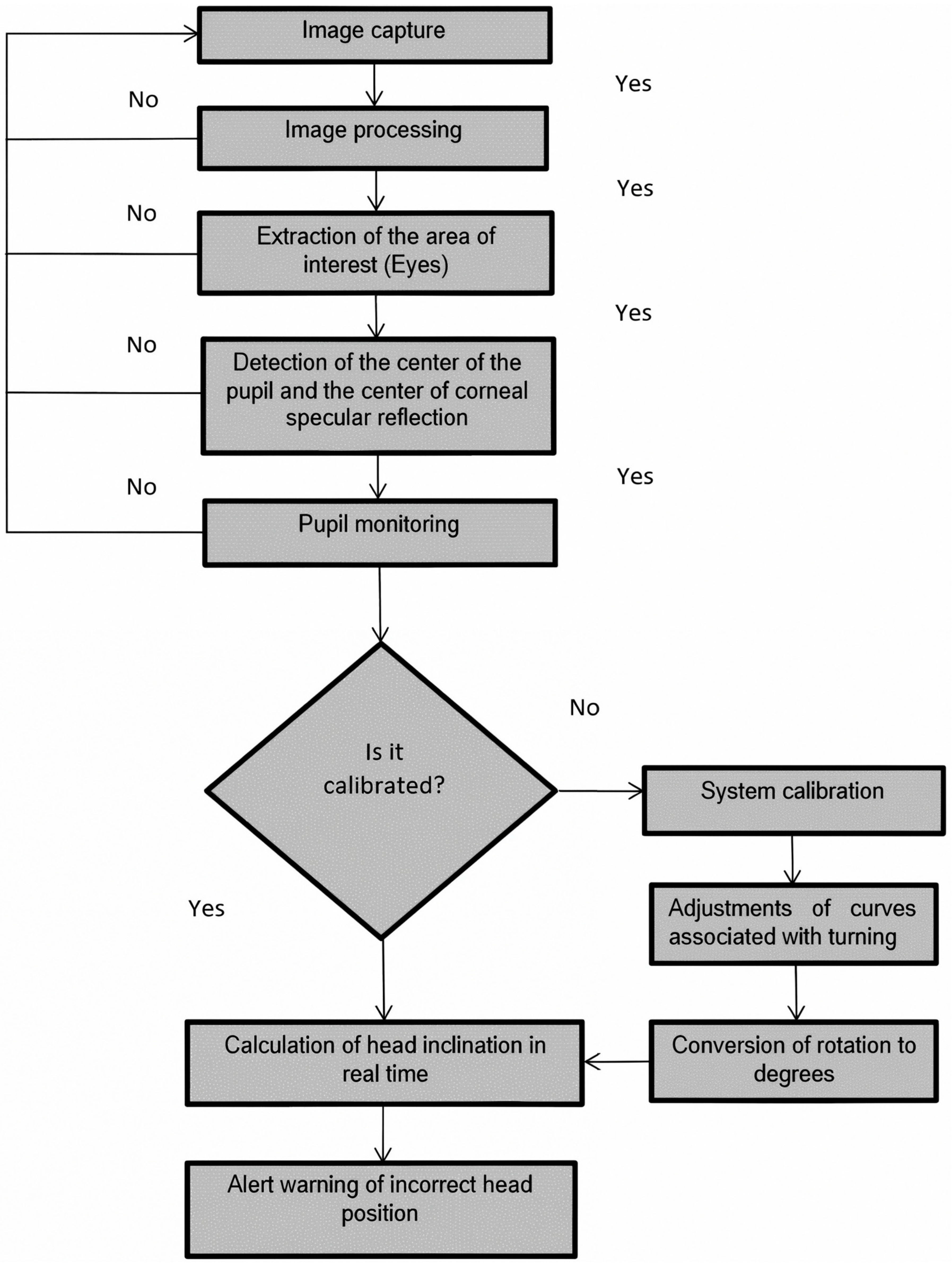
Figure 2.
Detection of the eyes.
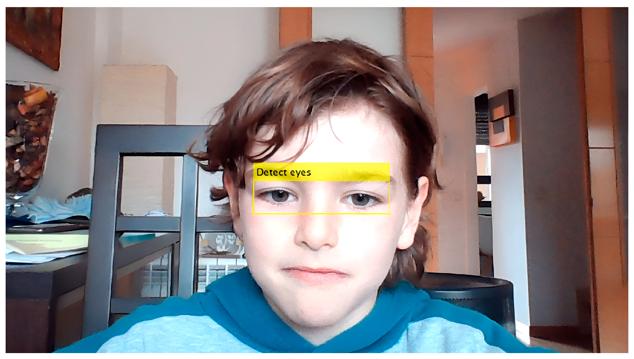
Figure 3.
Location of the iris and the center of corneal specular reflection.
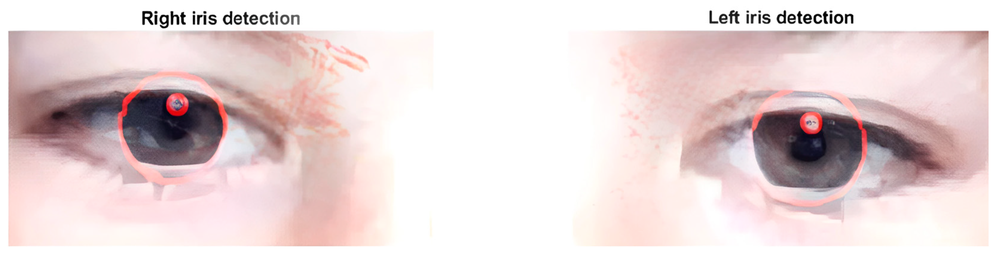
Figure 4.
Image showing real-time eye tracking, which allows obtaining the pixel coordinates of the right and left pupillary centers.
Figure 4.
Image showing real-time eye tracking, which allows obtaining the pixel coordinates of the right and left pupillary centers.
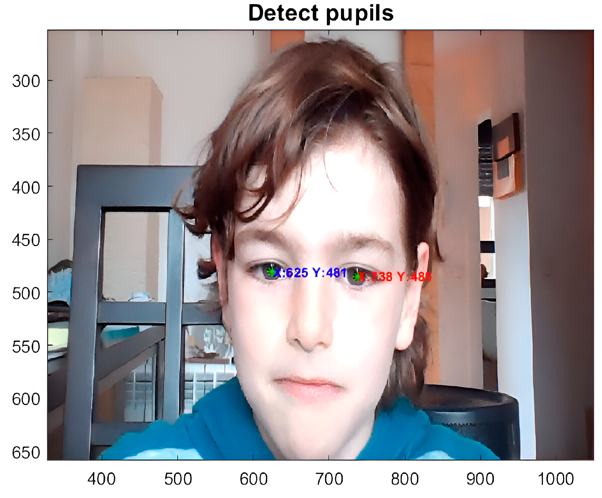
Figure 5.
Detection of the center of circles and their coordinates.
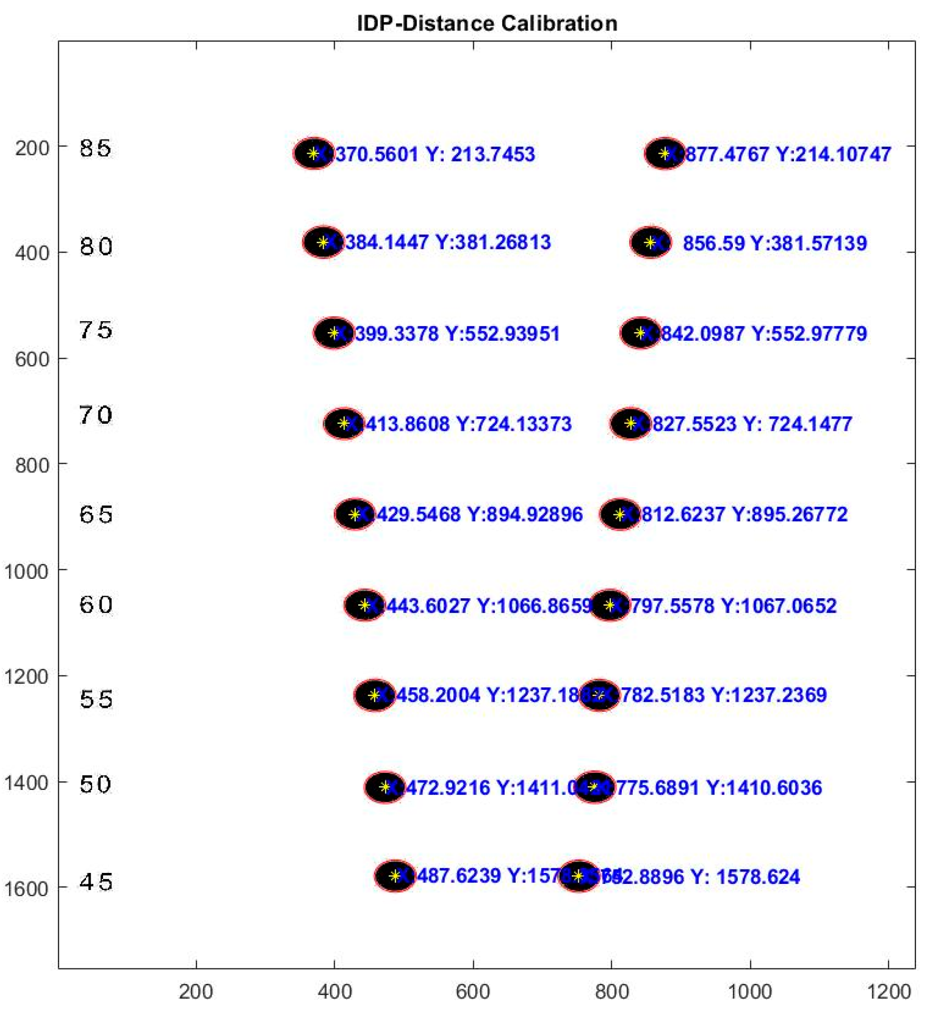
Figure 6.
a). Template with different distances between the circles standing for the different DIPs found in front of the laptop. (b). Template fixed to an optical goniometer to be calibrated at different inclinations.
Figure 6.
a). Template with different distances between the circles standing for the different DIPs found in front of the laptop. (b). Template fixed to an optical goniometer to be calibrated at different inclinations.
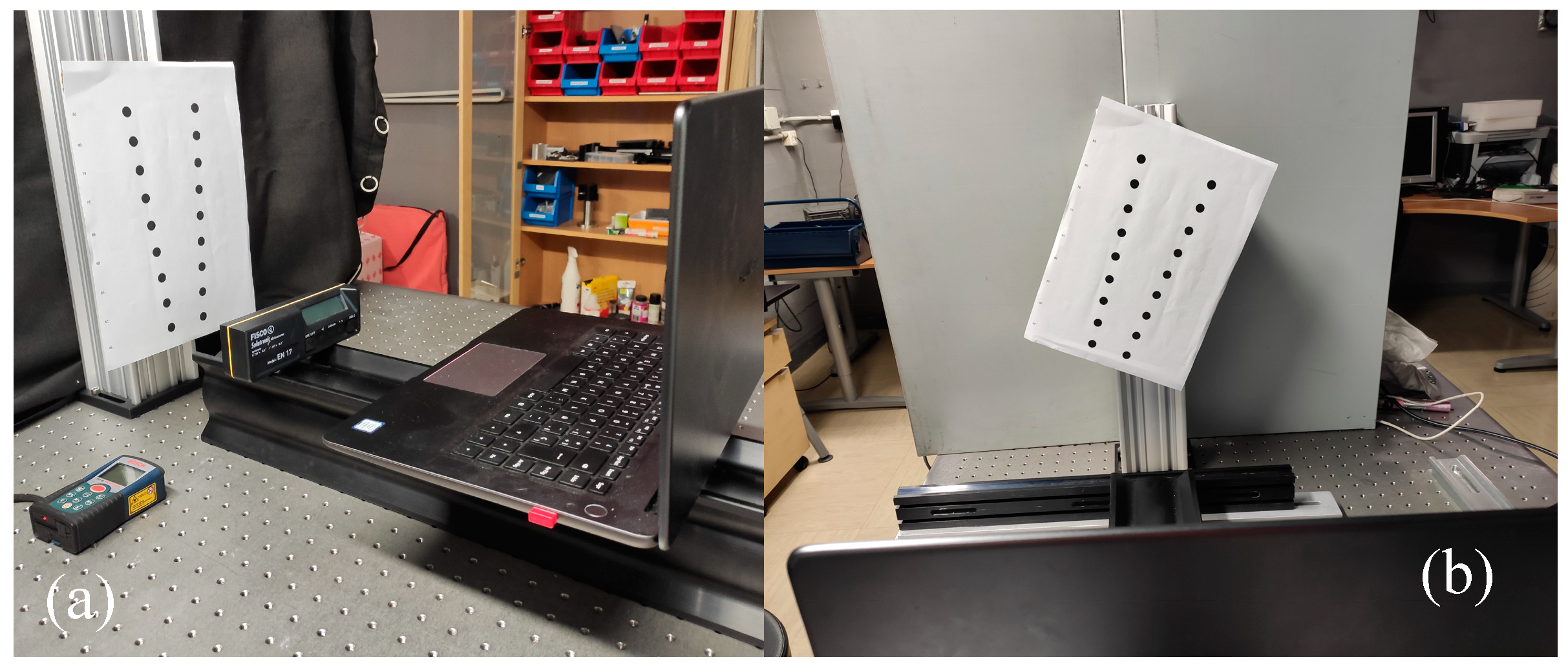
Figure 7.
Detection of the circles when there is a rotation of the template.
Disclaimer/Publisher’s Note: The statements, opinions and data contained in all publications are solely those of the individual author(s) and contributor(s) and not of MDPI and/or the editor(s). MDPI and/or the editor(s) disclaim responsibility for any injury to people or property resulting from any ideas, methods, instructions or products referred to in the content. |
© 2024 by the authors. Licensee MDPI, Basel, Switzerland. This article is an open access article distributed under the terms and conditions of the Creative Commons Attribution (CC BY) license (http://creativecommons.org/licenses/by/4.0/).
Copyright: This open access article is published under a Creative Commons CC BY 4.0 license, which permit the free download, distribution, and reuse, provided that the author and preprint are cited in any reuse.


