Submitted:
07 March 2025
Posted:
10 March 2025
You are already at the latest version
Abstract
For a two-stage variable-pitch axial fan, a perforation design in first-stage rotor blades was proposed to improve aerodynamic performance and reduce acoustic noise. Utilizing steady-state simulations in Fluent, the internal flow characteristics of the fan before and after perforation were studied, and the changes in noise and vortex structure were ex-amined by the large eddy simulation. Additionally, the perforation diameter with better performance was applied to the second-stage rotor blades and both first- and sec-ond-stage rotor blades, and the effects of perforation on blades of different stages were compared. The results show that an appropriate perforation diameter can improve the performance of the fan. Considering the changes in total pressure rise and efficiency, d=6mm is the optimal choice. Proper perforation diameter has a significant effect on noise suppression, and the noise reduction effect is more pronounced in the high-frequency range. Among the models, d=10mm shows the best noise reduction effect. At this perforation diameter, the vortex at the trailing edge of the rotor blades forms a regular ring-like vortex chain, resulting in lower noise levels. Perforating in the first-stage rotor blade can enhance the fan's performance, while perforating in the second-stage rotor blades leads to a decrease in performance. Additionally, perforation can effectively reduce the noise at each stage. Considering both performance and noise variations, the optimal perforation scheme is simultaneous perforating in the first- and second-stage rotor blades with a perforation diameter of 10mm.
Keywords:
variable-pitch axial fan
; blade perforation
; aerodynamic performance
; noise
; internal flow
1. Introduction
Axial flow fans have advantages including large volume flow rate and high efficiency, making them widely used in industries, transportation, and construction. However, the noise pollution generated during the operation has increasingly drawn attention [1], especially the aerodynamic noise produced during high-speed rotation. Therefore, reducing the aerodynamic noise of axial flow fans is of great practical significance for ensuring safe and stable operation as well as protecting the health of maintenance personnel.
As the working component of axial flow fans, optimizing the blades is one of the effective ways to improve fan performance. Common modification measures include trailing edge modifications, blade tip grooving, and blade perforations. Among them, Yin et al. [2] applied leading-edge wavy serrations, trailing-edge serrations, and ridge structures to an axial flow fan, designing a serrated trailing-edge fan and a coupled bionic fan. Experimental results showed that the coupled bionic structure could reduce mid-to-low-frequency noise, but its noise reduction effect in the high-frequency range was poor. Zheng et al. [3] modified the trailing-edge structure of a two-stage variable-pitch axial flow fan's rotor blades by adding serrated flap structures. Simulation results indicated that the serrated flap could improve the wake vortex structure of the rotor blades, thereby reducing its aerodynamic noise. Zhou et al. [4] examined the effects of various trailing-edge serration structures on fan noise, which indicated that serrated trailing edges could effectively reduce noise, with significantly better noise reduction performance at low frequencies compared to mid-to-high frequencies. Huang et al. [5] designed a novel inclined serrated trailing-edge fan using bending techniques based on a bionic serrated trailing-edge fan. Experimental results demonstrated that the inclined serrated trailing edge had a better noise reduction effect than traditional serrated trailing edges, with a maximum reduction of 2.38 dB in A-weighted sound level. Hickey et al. [6] conducted simulations on various blade tip winglets, revealing that suction-side winglets with a moderate-smooth profile had the most significant noise reduction effect, reducing the overall sound pressure level by 3.6 dB. Ryu et al. [7] investigated the effect of winglet curvature on axial flow fans, and experimental results showed that blades with greater winglet curvature variation could improve performance and reduce noise. Xu et al. [8] studied a multi-blade centrifugal fan by introducing a bionic groove structure at the impeller blade tips and found that the bionic grooves had a specific noise reduction effect while having little impact on its aerodynamic performance.
Existing studies have shown that perforating blades can effectively reduce aerodynamic noise. Chen et al. [9] designed perforated blades for a centrifugal fan, investigating the effects of different perforation shapes, diameters, and porosities on fan noise. Simulation results indicated that blade perforation can effectively reduce noise, and filling the blade interior with porous materials significantly enhanced the noise reduction effect. Wang et al. [10] numerically studied an annular cooling fan, designing a perforated structure and found that the perforations effectively reduced the formation of low-speed recirculation zones at the blade tip and suppressed vortex shedding, thereby lowering noise levels. Yang et al. [11] applied perforations to a large marine axial flow fan, and experimental results showed that the improvement in vortex shedding at the blade's trailing edge after tip perforation was the primary reason for the reduction in aerodynamic noise. Hu et al. [12] investigated perforation designs for a small twin-rotor axial flow fan, and simulation results indicated that perforations reduced aerodynamic noise, with noise levels decreasing as the number of perforations increased. Zhang et al. [13] designed perforations on the trailing edge of the blade of a small-scale axial flow fan. Simulation results revealed that an appropriate perforation diameter could improve blade surface pressure distribution and suppress tip leakage intensity, thereby reducing acoustic noise.
The above-mentioned studies on noise reduction primarily focus on flaps, winglets, and small fan blade perforations. However, no studies have been reported on blade perforation for large-scale variable-pitch axial flow fans. Additionally, the impact of different perforation diameters on fan aerodynamic performance and noise remains unclear. It should be mentioned that large-scale variable-pitch axial flow fans typically consist of two stages of rotor and stator blades, leading to complex internal flow dynamics that increase noise reduction challenges and costs. Hence, reducing aerodynamic noise in such fans is crucial for improving operational safety and protecting maintenance personnel. To address this gap, this study focuses on a two-stage variable-pitch axial primary air fan used in a 660 MW coal-fired power generation unit. First, a perforation design scheme is proposed for the first-stage rotor blades, and numerical simulations are conducted to analyze the effects of perforation diameter on the aerodynamic performance, internal flow characteristics, and aerodynamic noise of the axial fan. The optimal perforation scheme is then selected based on a comprehensive performance evaluation. Building on these findings, the selected perforation scheme is applied separately to the second-stage rotor blades and to both stages simultaneously, with comparisons made against the case where perforations are applied only to the first-stage rotor blades. Then, a referable perforated blade design scheme is obtained, which provides a theoretical foundation for the application of perforated blades in aerodynamic noise control for large-scale axial fans.
2. Methodology
2.1. Fan Model
As shown in Table 1, a two-stage variable-pitch axial flow fan consists of a collector, two stages of rotor blades, two stages of stator blades, and a diffuser. Every rotor stage contains 24 blades with identical airfoil profiles. The first-stage stator consists of 23 composite blades of varying lengths, while the second-stage stator consists of 23 short blades. The fan operates at a rotational speed of 1490 r/min, rotating counterclockwise when viewed from the motor side. The main parameters of the fan are listed in Table 1.
Considering that boundary layer separation generally occurs near the trailing edge [14], four holes were uniformly arranged along the blade height direction at Xc=0.75c on the trailing edge of the first-stage rotor blades of the fan. The rotor blade models before and after perforation are shown in Figure 1. The perforation angle was set to 30° [15], and the perforation diameters were selected as 2 mm, 4 mm, 6 mm, 8 mm, 10 mm, and 12 mm for this study. The specific parameters of the perforation position are shown in Figure 2.
2.2. Numerical Method and Boundary Conditions
The numerical simulations were conducted using Fluent software, with steady-state calculations based on the Multiple Reference Frame (MRF) model. The turbulence model in the governing equations was selected as the Realizable k–ε model, which has demonstrated significant improvements in handling flow characteristics involving strong streamline curvature, vortices, and rotation [16]. The near-wall region was treated using the standard wall function, while the pressure-velocity coupling was handled using the SIMPLEC algorithm to enhance convergence efficiency. A second-order upwind scheme was employed for the discretization of the dispersed phase. The interface boundary condition was applied to facilitate data exchange between different fluid regions. The inlet boundary condition was set as velocity inlet, while the outlet boundary condition was specified as free outflow. The simulation was considered converged when the residuals of all parameters were less than 10−5, and the total pressure at the fan's inlet and outlet remained constant.
To clarify the noise variations and vortex structure characteristics, the steady-state results are used as the initial field for large eddy simulation (LES) in transient calculations. Near-field noise is computed using Computational Aeroacoustics (CAA), where pressure variation time-series data at monitoring points are collected and then processed using the Fast Fourier Transform (FFT) to obtain the noise spectrum. Far-field noise is analyzed using the Ffowcs Williams-Hawkings (FW-H) acoustic model, which extracts relevant time-domain information at designated positions, effectively decoupling acoustic analysis from the fluid flow solution and accurately predicting the noise generated by equivalent sound sources [17]. For transient calculations, the time step corresponds to the time required for the rotor blade to rotate by 1°, which is 1.1186×10⁻⁴s. The total number of time steps is 1080, with the maximum number of iterations for each time step is 20.
2.3. Validation of Grid Independence
To optimize computational resources and consider the periodic characteristics of fan operation, a single-passage fan model is adopted, as shown in Figure 3. The axial flow fan is modeled using SpaceClaim software, and unstructured meshing is performed with Fluent Meshing. A boundary layer mesh is applied to the rotor blade surface, with the first layer height set to 4.4×10⁻⁵ to ensure y+<1, and the growth rate is set to 1.2, satisfying the grid resolution requirements for LES.
Simulations were conducted on the original fan model with total mesh counts of 1.89 million, 2.96 million, 4.19 million, 5.78 million, and 7.61 million. The results indicated that the total pressure rise difference between the 5.78 million and 7.61 million mesh models was minimal. To balance computational accuracy and efficiency, the 5.78 million mesh model was selected for the following calculations.
2.4. Verification of Numerical Simulation
A comparison between the steady-state simulation results of the original fan model and the reference sample values [18] is shown in Figure 4. Within the volumetric flow rate range of 80–92.5 m³/s, the average deviations of total pressure rise and efficiency are 1.07% and 2.94%, respectively, both of which are below 5%, which indicates that the simulation results can accurately reflect the operational state of the fan.
3. Results and Discussion
3.1. Aerodynamic Performance
Figure 5 shows the total pressure rise and efficiency curves of the original fan and the perforated fan models with different perforation diameters. Figure 5(a) indicates that the total pressure rise of all fan models decreases with increasing flow rate. When qv<82.5m3/s, it is found that except for d=2mm model, the total pressure rise of all perforated fan models is higher than that of the original fan. When qv>82.5m3/s, it is evident that compared with the original fan, the total pressure rise of the d=6mm fan model slightly increases, while that of the d=10mm and 12mm fan models decreases. At the design flow rate qv=82.5m3/s, compared to the original fan, the total pressure rise variations for each model with increasing perforation diameter are −23.0 Pa, 14.1 Pa, 72.0 Pa, 66.4 Pa, 46.2 Pa, and 22.8 Pa, respectively, which indicates that d=6mm provides the greatest improvement in total pressure rise at the design flow rate.
Figure 5(b) shows that each fan model achieves maximum efficiency at the design flow rate, and the efficiency decreases when the flow rate deviates from the design value. In the low flow rate region where qv<82.5m3/s, compared with the original fan, the efficiency of the d=6mm fan model increases, while the efficiency of the other perforated fan models is similar to that of the original fan. In the high flow rate region where qv>82.5m3/s, the efficiency of the d=6mm fan model is similar to that of the original fan, while the efficiency of the other perforation diameter models is lower than that of the original fan. Under the designed flow rate, compared with the original fan, the fan efficiency of each model changed by −0.074, −0.012, 0.109, 0.065, 0.034, and 0.003 percentage points as the perforation diameter increased. This demonstrates that the fan model with d=6mm achieves the highest efficiency improvement. The performance variation with perforation diameter obtained in this study is similar to the conclusions drawn by Zhang et al. [18].
The above results indicate that blade perforation has a certain impact on the aerodynamic performance of the fan, and an appropriate perforation diameter can enhance fan performance. Based on the combined analysis of total pressure rise and efficiency, 6mm is identified as the optimal perforation diameter.
3.2. Internal Flow Characteristics
This section analyzes the internal flow characteristics near the perforations to further investigate the intrinsic mechanism of how blade perforation affects fan performance. Since the blade's primary working region is located in its upper-middle portion [13], a cross-section A is defined along the central axis of the perforation at 80% blade height for analysis, as illustrated in Figure 6.
2.2.1. Static Pressure Distribution
Figure 7 presents the static pressure distribution at cross-section A under different perforation diameters. As shown in Figure 7(a), when airflow encounters the leading edge of the rotor blade, it is obstructed by the blade surface, resulting in a localized high-pressure region I. As the flow moves from the leading edge to the trailing edge, the static pressure gradually increases, with an additional low-pressure region II appearing near the leading edge on the suction side and an additional high-pressure region III near the trailing edge on the pressure side. A comparison of Figures 7(a)–(g) reveals that blade perforations have a minimal impact on the overall static pressure distribution in the rotor blade region, with effects primarily localized around the perforation. Specifically, after perforation, the high-pressure region on the pressure side shifts downstream along the flow direction and its central pressure value further increases. Simultaneously, a low-pressure region forms on the suction side downstream of the perforation. As the perforation diameter increases, the static pressure in the upstream region of the perforation on the pressure side gradually decreases, while the high-pressure region downstream of the perforation expands. Similarly, the low-pressure region downstream of the perforation on the suction side also increases in size. The complex variations in local static pressure lead to non-monotonic changes in the total pressure rise of the axial flow fan as the perforation diameter changes.
2.2.2. Vorticity Distribution
Trailing vortices at the blade's trailing edge typically exhibit high vorticity and complex distribution. To analyze the influence of different perforation diameters on the vorticity distribution of trailing vortices, Figure 8 presents the vorticity contour near the trailing edge of cross-section A. As shown in Figure 8(a), the original fan model exhibits high-vorticity regions on the pressure side, suction side, and downstream of the trailing edge. Among these regions, the vorticity on the pressure side is relatively lower and confined to a limited region. In contrast, on the suction side, a distinct high-vorticity region forms near the wall, with vorticity gradually decreasing as the distance from the wall increases. The vortices from the pressure and suction sides mix downstream of the trailing edge, forming an extensive wake vortex that extends in the trailing edge direction.
A comparison of Figures 8(a)–(g) reveals that, compared to the original fan model, all perforated models exhibit a reduction in overall vorticity. Notably, the vorticity on the pressure side of the trailing edge decreases significantly in all perforated models, indicating that perforations substantially improve the flow on the pressure side. On the suction side, as the perforation diameter increases, the vorticity near the wall gradually decreases while a newly formed separation vortex appears in regions further from the wall. Nevertheless, both the overall vorticity magnitude and its spatial extent exhibit a diminishing trend. The wake vortex, which results from the mixing of vortices from the pressure and suction sides, diminishes as the perforation diameter increases. This reduction is due to the gradual decrease in vorticity on both sides of the blade, leading to a corresponding decline in the vorticity magnitude and extension range of the wake vortex.
The above results indicate that blade perforation has a significant suppressing effect on the vorticity near the trailing edge, which is consistent with the findings of Wang et al. [15], and the suppression effect becomes more pronounced as the perforation diameter increases. An appropriate blade perforation design can effectively improve the characteristics of the trailing-edge vortex, thereby enhancing the overall performance of the fan.
3.3. Noise Distribution
To analyze the impact of blade perforation diameter on aerodynamic noise, four monitoring points (M1-M4) are set at 20%, 40%, 60%, and 80% of the blade height behind the trailing edge of the first-stage rotor blade. These points are used to monitor the instantaneous pressure fluctuations in the wake region of the first-stage rotor blade, as shown in Figure 9.
The sound pressure level (SPL) is defined as: Lp=20lg(p/p0), where p0 is the reference sound pressure, with a value of 2×10⁻⁵Pa. Figure 10 presents the total SPL at monitoring points M1–M4 for both the original fan and perforated fan models with varying perforation diameters. As shown in Figure 10, for the same model, noise levels at M1 and M4 are higher than those at M2 and M3. This is because M1 is located near the blade root, where the hub obstruction effect generates additional attached vortices, leading to increased aerodynamic noise. In contrast, M4 is positioned near the blade tip, where tip leakage flow significantly affects pressure fluctuations, resulting in a notable increase in noise levels [19]. Furthermore, the noise levels at all monitoring points exhibit a decreasing trend as the perforation diameter increases. Comparing the results with the original fan model, the models with d=10mm and d=12mm exhibit superior noise reduction performance. Specifically, for the d=10mm model, the SPL reductions at M1–M4 are 3.98 dB, 2.19 dB, 3.66 dB, and 5.50 dB, respectively. For the d=12mm model, the reductions are 3.11 dB, 2.09 dB, 1.23 dB, and 6.86 dB, respectively.
To further investigate the noise reduction effects of different perforation diameters across various frequency bands, Figure 11 presents the noise spectra at four monitoring points for both the original fan model and the perforated fan models. The fundamental frequency f of the noise generated by the periodic pressure pulsation due to blade rotation is given by f=Zn/60, where Z represents the number of blades, and n denotes the impeller rotational speed. Substituting the fan parameters yields a fundamental frequency of 596 Hz for this fan. As shown in Figure 11, the SPL of all models reaches its maximum at the fundamental frequency. The noise spectra of different models can be broadly categorized into a low-frequency range (below 2000 Hz) and a high-frequency range (above 2000 Hz). In the low-frequency range, the SPL exhibits significant fluctuations and gradually decreases with increasing frequency. Conversely, in the high-frequency range, the SPL remains relatively stable, fluctuating within a small range across all models.
At monitoring point M1, the SPL of all perforated fan models is lower than that of the original fan model across the entire frequency range, with a more pronounced noise reduction effect in the high-frequency region. Specifically, in the high-frequency range, the original fan model has the highest SPL, approximately 73 dB, while the d=12mm model has the lowest SPL, approximately 60 dB. At monitoring points M2 and M3, the noise spectra of different models exhibit a similar distribution. At the fundamental frequency, the SPL of the original fan model is slightly higher than that of the perforated fan models, but in the high-frequency range, the SPL differences among models are minimal, which is consistent with the observation in Figure 10, where the perforated models show a less significant noise reduction effect at M2 and M3.
The noise spectrum at monitoring point M4 follows a trend similar to that at M1, where the SPL of all perforated fan models remains lower than that of the original fan model across all frequency bands. In the high-frequency range, the SPL of the d=10mm model is the lowest, approximately 59 dB. These results demonstrate that an appropriately selected perforation diameter can effectively suppress fan noise. Considering the overall performance and noise reduction data, the optimal perforation diameter is determined to be 10 mm.
3.4. Vortex Structures
The variable-pitch axial flow fan's rotor blades adopt twisted and curved blades, resulting in a highly complex internal flow structure. To further examine the underlying reasons for the impact of perforation diameter on fan noise, the Q-criterion method is introduced to analyze the vortex structure. The Q-criterion is used to characterize transient vortex structures, providing an intuitive description of the vortex's structure and location. The Q-value represents the second invariant of the velocity gradient tensor and is defined by the following equation:
where Ωi represents the vorticity tensor, and Sij denotes the strain rate tensor.
According to the study of Hunt et al. [20], vortices are identified in regions where the second invariant of the velocity gradient tensor satisfies Q>0. In such regions, the rotational component of the fluid dominates over the strain component, leading to the formation of vortex structures. To inspect the effect of blade perforation on aerodynamic noise, Figure 12 presents the vortex structures identified on the blade surface at a design flow rate under Q=9×10⁵ conditions.
As illustrated in Figure 12(a), the flow at the leading edge of the blade exhibits stable laminar behaviors, with no significant changes in the spanwise vortex structures. However, as the flow progresses downstream, boundary layer separation disrupts the stability of the laminar region, leading to the formation of new separation vortices. Subsequently, due to the interaction between suction-side and pressure-side airflow, complex wake vortices are generated and develop downstream along the mainstream direction. In the blade tip region, the presence of tip leakage flow further complicates the local vortex structures, which tend to diffuse outward from the blade tip gap. A comparison of Figures 12(a)–12(g) reveals that blade perforations significantly impact vortex structures. When the perforation diameter is small, the wake vortex structure remains essentially unchanged. However, for larger perforation diameters, evident vortex fragmentation occurs near the perforation site, forming a well-defined ring-shaped vortex chain. Overall, large-scale vortices break down into smaller-scale vortices after perforation, reducing vortex size, which in turn diminishes local pressure fluctuations, ultimately contributing to a reduction in aerodynamic noise in the affected region [21].
3.5. Different Stage Blades Perforation
The above analysis indicates that perforating in the first-stage rotor blades provides a significant noise reduction effect for the axial flow fan studied in this study. Considering that this fan consists of two stages of rotor blades, the optimal d=10mm perforation scheme is applied to different rotor stages for further investigation. The study considers three scenarios: only the first-stage rotor blades are perforated (Scheme 1); only the second-stage rotor blades are perforated (Scheme 2); and both the first- and second-stage rotor blades are perforated (Scheme 3).
3.5.1. Performance of Different Stage Blades Perforation
The performance of the fan models under different perforation schemes is presented in Figure 13. As shown in Figure 13(a), the total pressure rise of all schemes decreases as the flow rate increases. When qv<82.5m3/s, the total pressure rise of Scheme 1 and Scheme 3 is higher than that of the original fan, whereas the total pressure rise of Scheme 2 is lower. This indicates that in the low flow rate region, perforating in the first-stage rotor blades can enhance the total pressure rise of the fan, while perforating in the second-stage rotor blades leads to a reduction in total pressure rise. When qv>82.5m3/s, the total pressure rise of all perforated schemes is lower than that of the original fan, suggesting that at high flow rates, perforations in either the first-stage or second-stage rotor blades result in a decrease in total pressure rise. At the design flow rate, the changes in total pressure rise relative to the original fan for the three schemes are 46.22 Pa, −68.44 Pa, and 6.131 Pa, respectively.
Figure 13(b) illustrates that all models achieve their highest efficiency at the design flow rate, and the efficiency variations for different models exhibit a trend similar to that of total pressure rise at the same flow rate. When qv<82.5m3/s, the efficiency of Scheme 1 and Scheme 3 is nearly identical, and both are higher than that of the original fan, whereas the efficiency of Scheme 2 is lower than that of the original fan. This indicates that in the low flow rate region, perforating the first-stage rotor blades can enhance fan efficiency, while perforating the second-stage rotor blades reduces efficiency. When qv>82.5m3/s, the efficiency of the original fan is higher than that of the perforated fans, with Scheme 3 exhibiting the lowest efficiency. This suggests that at high flow rates, perforations in either the first-stage or second-stage rotor blades lead to reductions in both total pressure rise and efficiency.
These findings demonstrate that under the design flow rate, perforating the first-stage rotor blades improves fan performance, while perforating the second-stage rotor blades degrades performance. Therefore, Scheme 1 provides the optimal performance enhancement for the fan.
3.5.2. Noise of Different Stage Blade Perforation
To analyze the impact of three perforation schemes on aerodynamic noise, eight monitoring points (M1–M4, N1–N4) were placed at 20%, 40%, 60%, and 80% of the blade height along the trailing edges of the first-stage and second-stage. These monitoring points were used to capture the instantaneous pressure fluctuations in the trailing-edge regions of both rotor stages. The specific locations of the monitoring points are illustrated in Figure 9.
Figure 14 presents a comparison of the overall SPLs at different monitoring points under the design flow condition. The results indicate that for both the three perforating schemes and the original fan, the highest noise levels were observed at monitoring points M4 and N4, located near the blade tip. This finding suggests that tip leakage flow has a significant impact on noise generation [18]. Additionally, the perforations effectively reduce the noise of the corresponding rotor stage but have a relatively minor effect on noise reduction in the other rotor stage. Under the design flow condition, the second-stage rotor blade perforations result in a more minor noise reduction compared to the first-stage perforations. This is attributed to the higher pressure and noise levels in the second-stage rotor, which makes noise suppression more challenging. Consequently, the influence of blade perforations on the second-stage rotor is less pronounced, but a certain degree of noise reduction is still achieved. Overall, Scheme 3 demonstrated the best comprehensive noise reduction performance. The total SPLs at monitoring points M1–M4 decrease by 6.23 dB, 2.60 dB, 3.45 dB, and 4.09 dB, respectively, while those at monitoring points N1–N4 decrease by 1.98 dB, 1.91 dB, 1.58 dB, and 0.12 dB, respectively.
The above analysis shows that Scheme 3 is the optimal modification approach, as it effectively reduces aerodynamic noise without compromising aerodynamic performance.
4. Conclusion
Blade perforation has a certain impact on the aerodynamic performance of the axial flow fan. When the flow rate is low, blade perforation with an appropriate diameter can improve fan performance, but in high flow rate regions, it may lead to a decline in performance. Considering the variations in total pressure rise and efficiency, the optimal perforation diameter for aerodynamic performance is 6 mm, which increases the total pressure rise by 72 Pa and improves efficiency by 0.109 percentage points at the design flow rate.
After perforation, large-scale vortices break into smaller-scale vortices, reducing pressure fluctuations and consequently lowering aerodynamic noise. A properly chosen perforation diameter significantly suppresses the noise, with a more pronounced effect on high-frequency noise. Based on comprehensive performance and noise reduction analysis, the optimal perforation diameter for noise suppression is 10 mm, whose SPLs at M1 to M4 are reduced by 3.98 dB, 2.19 dB, 3.66 dB, and 5.50 dB, respectively, compared to the original fan.
At the design flow rate, perforating in the first-stage rotor blades improves the fan performance, whereas perforating in the second-stage rotor blades results in a performance decline. In high-flow rate regions, perforation generally leads to performance degradation. In terms of noise reduction, the first-stage blade perforation achieves a greater noise reduction than the second-stage blade perforation, while the simultaneous perforation of both stage blades yields the best noise suppression. Considering both aerodynamic performance and noise reduction, the optimal perforation scheme is Scheme3.
Author Contributions
Methodology, C.Q. and X.Y.; Software, C.Q.; Validation, C.Q. and Y.H.; Formal analysis, C.Q., X.Y. and C.L.; Investigation, C.Q., Y.H and X.Y.; Data curation, C.Q. and Y.H.; Writing—original draft, C.Q. and X.Y.; Writing—review & editing, C.L. and X.Y. All authors have read and agreed to the published version of the manuscript.
Conflicts of Interest
The authors declare no conflict of interest.
Abbreviations
The following abbreviations are used in this manuscript:
| MRF | Multiple Reference Frame |
| LES | large eddy simulation |
| CAA | Computational Aeroacoustics |
| FFT | Fast Fourier Transform |
| FW-H | Ffowcs Williams-Hawkings |
| SPL | sound pressure level |
References
- Sun, Y.; Li, R.; Wang, L.; Liu, C.; Yang, Z.; Ma, F. , Bionic noise reduction design of axial fan impeller. J Phys D Appl Phys 2024, 57, (34). [Google Scholar]
- Yin, W.; Yang, A.; Chen, E.; Lu, C. , Experimental Study on Aerodynamic Noise Characteristics of Bionic Axial Flow Fans. Journal of Engineering for Thermal Energy and Power 2022, 37, 51–59. [Google Scholar]
- Zheng, N.; Ye, X.; Yang, T.; Li, C. , Simulation Study on Aerodynamic Performance of Axial Flow Fan with Serrated Flaps Trailing Edge. Journal of Chinese Society of Power Engineering 2022, 42, (05), 450–457. [Google Scholar]
- Zhou, W.; Zhou, P.; Xiang, C.; Wang, Y.; Mou, J.; Cui, J. , A Review of Bionic Structures in Control of Aerodynamic Noise of Centrifugal Fans. Energies 2023, 16, (11), 4331. [Google Scholar] [CrossRef]
- Huang, Q.; Chen, E.; Yang, A.; Liu, J. , Experimental Study on Noise Reduction of an Axial Flow Fan with Inclined Serrated Trailing Edge. Journal of Chinese Society of Power Engineering 2020, 40, (09), 735–741. [Google Scholar]
- Hickey, J.; Zhao, W.; Persoons, T. , Experimental and numerical investigation of winglet designs for optimized performance of small axial fans. Appl Acoust 2025, 231. [Google Scholar]
- Seo-Yoon Ryu, C.C.J.W. , Analysis of aerodynamic and aeroacoustic performances of axial flow fans with variable winglet curvature in chordwise direction. Results Eng 2024, 21, 101857. [Google Scholar]
- Xu, Z.; Liu, X.; Liu, Y.; Qin, W.; Xi, G. , Flow Control Mechanism of Blade Tip Bionic Grooves and Their Influence on Aerodynamic Performance and Noise of Multi-Blade Centrifugal Fan. Energies 2022, 15, (9), 3431. [Google Scholar] [CrossRef]
- Chen, B.; Li, J.; He, J.; Xu, J.; Wang, Y. , Influence of blade perforation on acoustic performance of the centrifugal fan. Journal of Mechanical & Electrical Engineering 2023, 40, (08), 1267–1275. [Google Scholar]
- Wang, H.; Wang, L.; Liu, H.; Wang, B.; Hu, L. , Influence of blade perforation number on aerodynamic performance and noise performance of cooling fan. Journal of Mechanical & Electrical Engineering 2024, 41, (02), 302–310. [Google Scholar]
- Yang, X.; Wu, C.; Wen, H.; Zhang, L. , Numerical simulation and experimental research on the aerodynamic performance of large marine axial flow fan with a perforated blade. Journal of Low Frequency Noise, Vibration and Active Control 2018, 37, (3), 410–421. [Google Scholar]
- Hu, Y.J.; Wang, Y.P.; Li, G.Q.; Jin, Y.Z.; Setoguchi, T.; Kim, H.D. , Effects of Perforation Number of Blade on Aerodynamic Performance of Dual-rotor Small Axial Flow Fans. J Therm Sci 2015, 24, (2), 123–130. [Google Scholar] [CrossRef]
- Zhang, J.; Sai, Q.; Yan, Y., Effect of Blade Perforation Diameter on Aerodynamic Performance and Noise of Small Axial Fan. Journal of Chongqing Technology and Business University(Natural Science Edition) 2024, (1-11).
- Ma, R. Performance Analysis and Optimal Design of the Hollow Rotor Blades with Trailing Edge Self-induced Blowing. Master, Huazhong University of Science and Technology, 2013.
- Wang, S.; Yang, A.; Li, G.; Chen, E.; Wu, C. , Influence of hole type and incline angle on the aerodynamic and noise characteristics of perforated blade. Journal of University of Shanghai for Science and Technology 2021, 43, (06), 528–535. [Google Scholar]
- Li, C.; Lin, Q.; Ding, X.; Ye, X. , Performance, aeroacoustics and feature extraction of an axial flow fan with abnormal blade angle. Energy 2016, 103, 322–339. [Google Scholar]
- Su, Z.; Liu, E.; Xu, Y.; Xie, P.; Shang, C.; Zhu, Q. , Flow field and noise characteristics of manifold in natural gas transportation station. Oil Gas Sci Technol 2019, 74, 70. [Google Scholar] [CrossRef]
- Yang, T.; Ye, X.; Liu, Y.; Li, C. , Numerical Study on the Influence of Blade Tip Slot and Winglet on the Performance and Noise of Axial Fans. Journal of Chinese Society of Power Engineering 2023, 43, (09), 1123–1131. [Google Scholar]
- Zheng, N.; Ye, X.; Hu, J.; Li, C. , Effect of Toothed Flap Trailing Edge Blades on the Aerodynamic Noise of an Axial Fan. Journal of Engineering for Thermal Energy and Power 2022, 37, (09), 50–58. [Google Scholar]
- Hunt, J.C.R.; Wray, A.A.; Moin, P. , Eddies, streams, and convergence zones in turbulent flows. Center for Turbulence Research 1988, 193–208. [Google Scholar]
- Ye, X.; Zhang, R.; Zhang, C.; Li, C. , Aeroacoustics and Performance of an Axial-flow Fan with Serrated Trailing Edge Blades. Journal of Chinese Society of Power Engineering 2020, 40, (03), 239–246. [Google Scholar]
Figure 1.
Diagram of the blade model before and after perforation.
Figure 2.
Diagram of perforation position and perforation angle.
Figure 3.
Diagram of a single flow passage model.
Figure 4.
Comparison of simulated and experimental results.
Figure 5.
Effect of perforated blade on (a) total pressure rise and (b) efficiency characteristic curves.
Figure 5.
Effect of perforated blade on (a) total pressure rise and (b) efficiency characteristic curves.
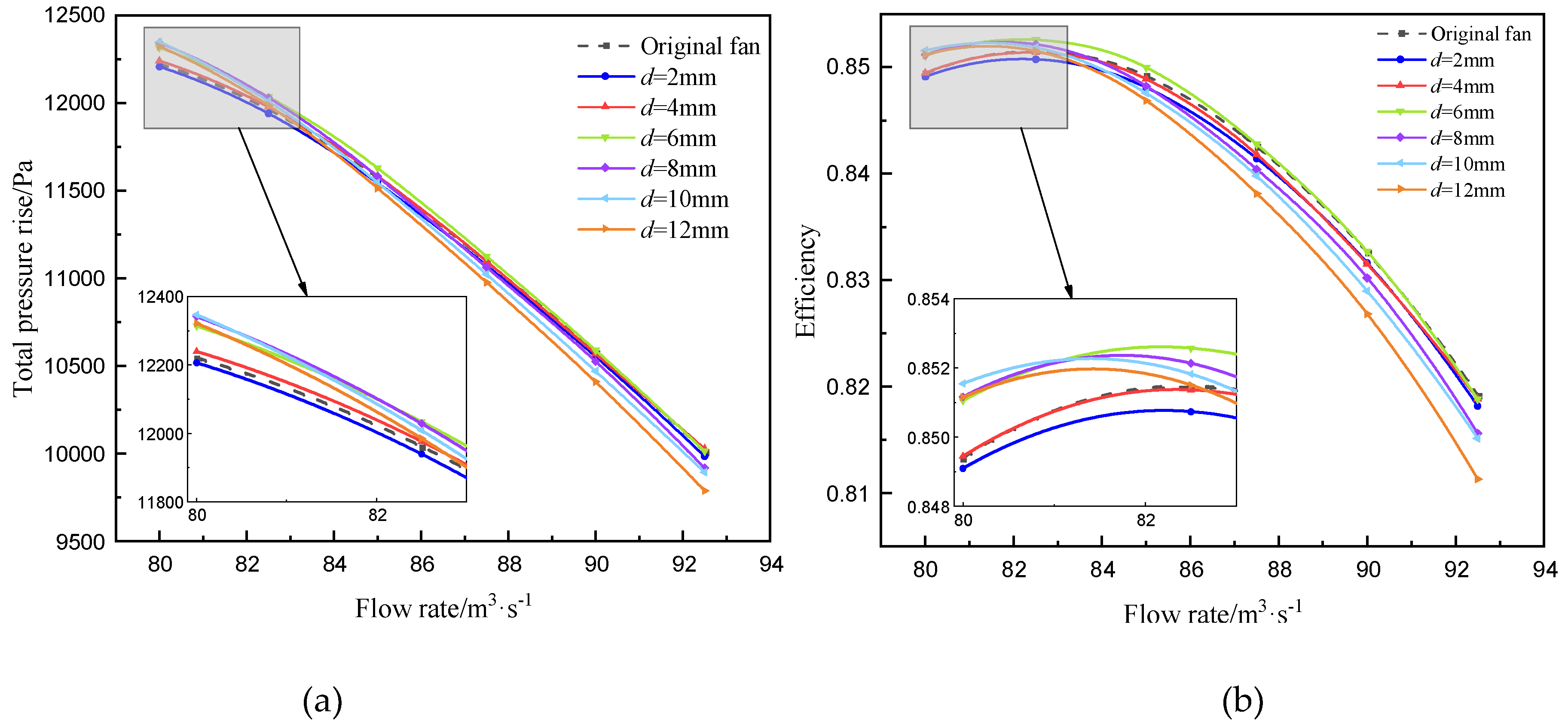
Figure 6.
Diagram of cross-section A along the central axis of the perforation at 80% blade height.
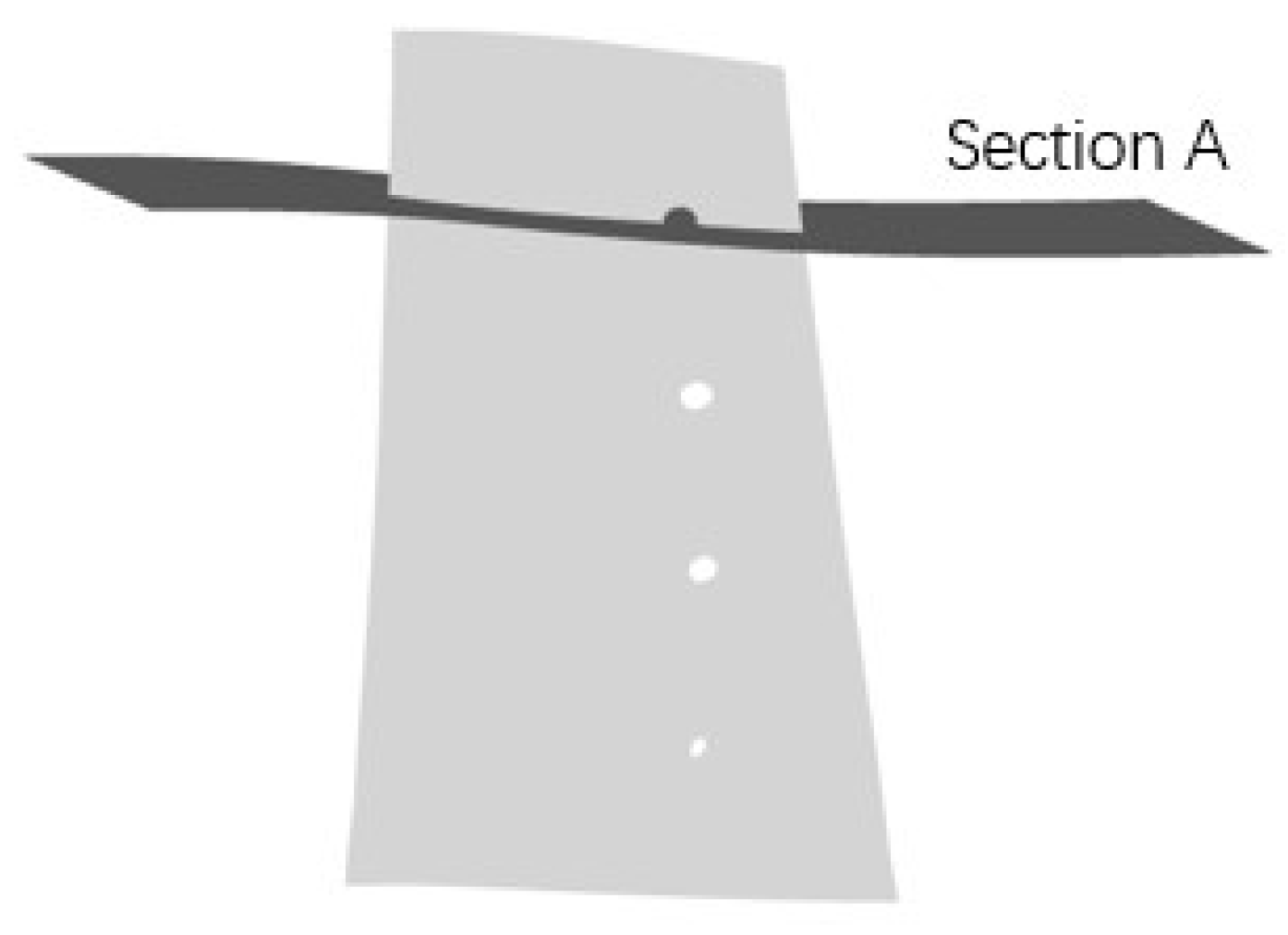
Figure 7.
Static pressure distribution in section A of (a) the original fan, (b) d=2mm, (c) d=4mm, (d) d=6mm, (e) d=8mm, (d) d=10mm and (g) d=12mm fan models.
Figure 7.
Static pressure distribution in section A of (a) the original fan, (b) d=2mm, (c) d=4mm, (d) d=6mm, (e) d=8mm, (d) d=10mm and (g) d=12mm fan models.
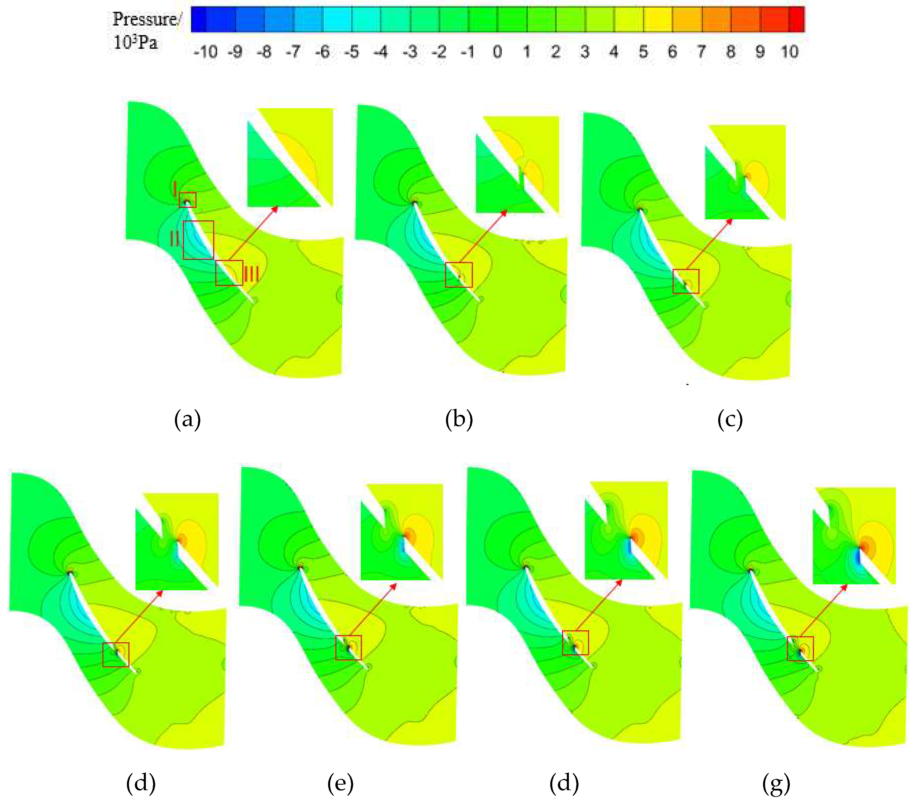
Figure 8.
Vorticity distribution in section A of (a) the original fan, (b) d=2mm, (c) d=4mm, (d) d=6mm, (e) d=8mm, (d) d=10mm and (g) d=12mm fan models.
Figure 8.
Vorticity distribution in section A of (a) the original fan, (b) d=2mm, (c) d=4mm, (d) d=6mm, (e) d=8mm, (d) d=10mm and (g) d=12mm fan models.
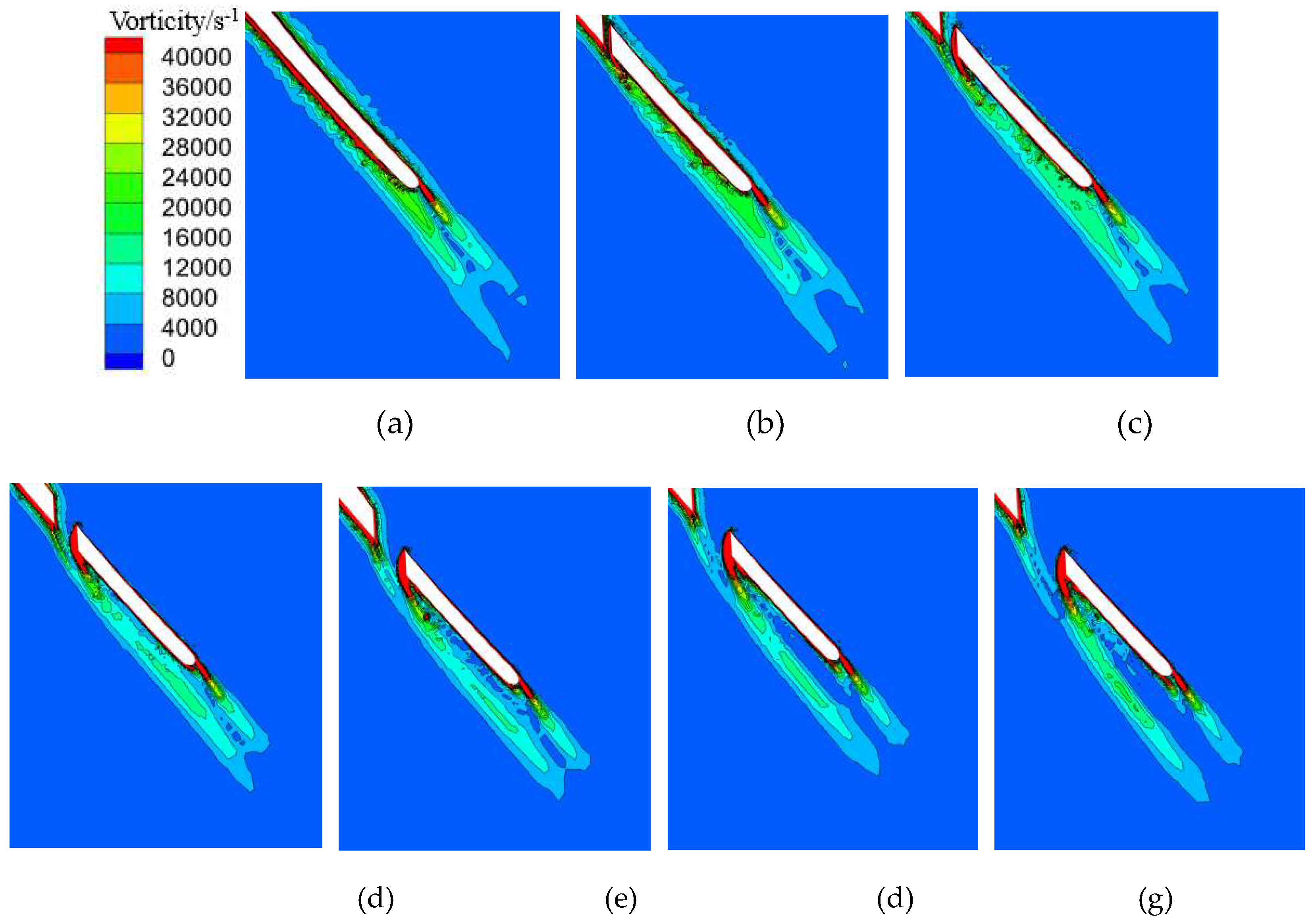
Figure 9.
Arrangement of noise monitoring points.
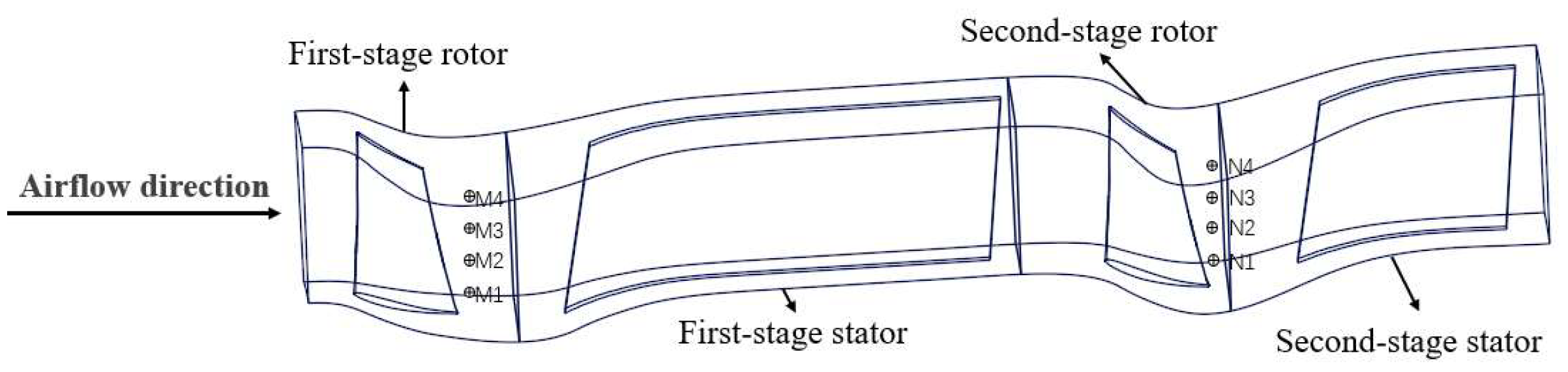
Figure 10.
Total sound pressure level of the monitoring points under design flow rate.
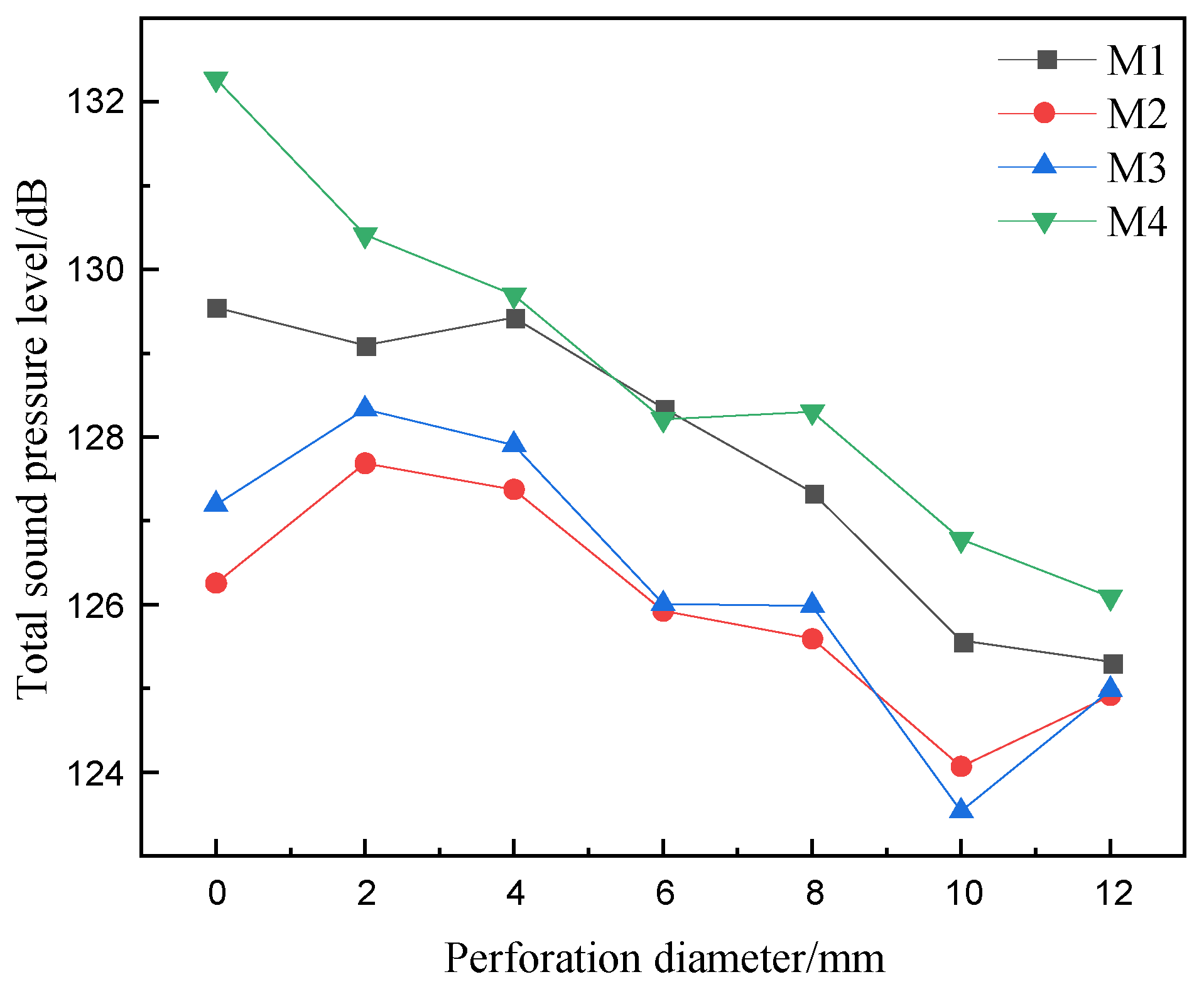
Figure 11.
Noise spectrum of the monitoring points (a) M1, (b) M2, (c) M3 and (d) M4 under the design flow rate.
Figure 11.
Noise spectrum of the monitoring points (a) M1, (b) M2, (c) M3 and (d) M4 under the design flow rate.
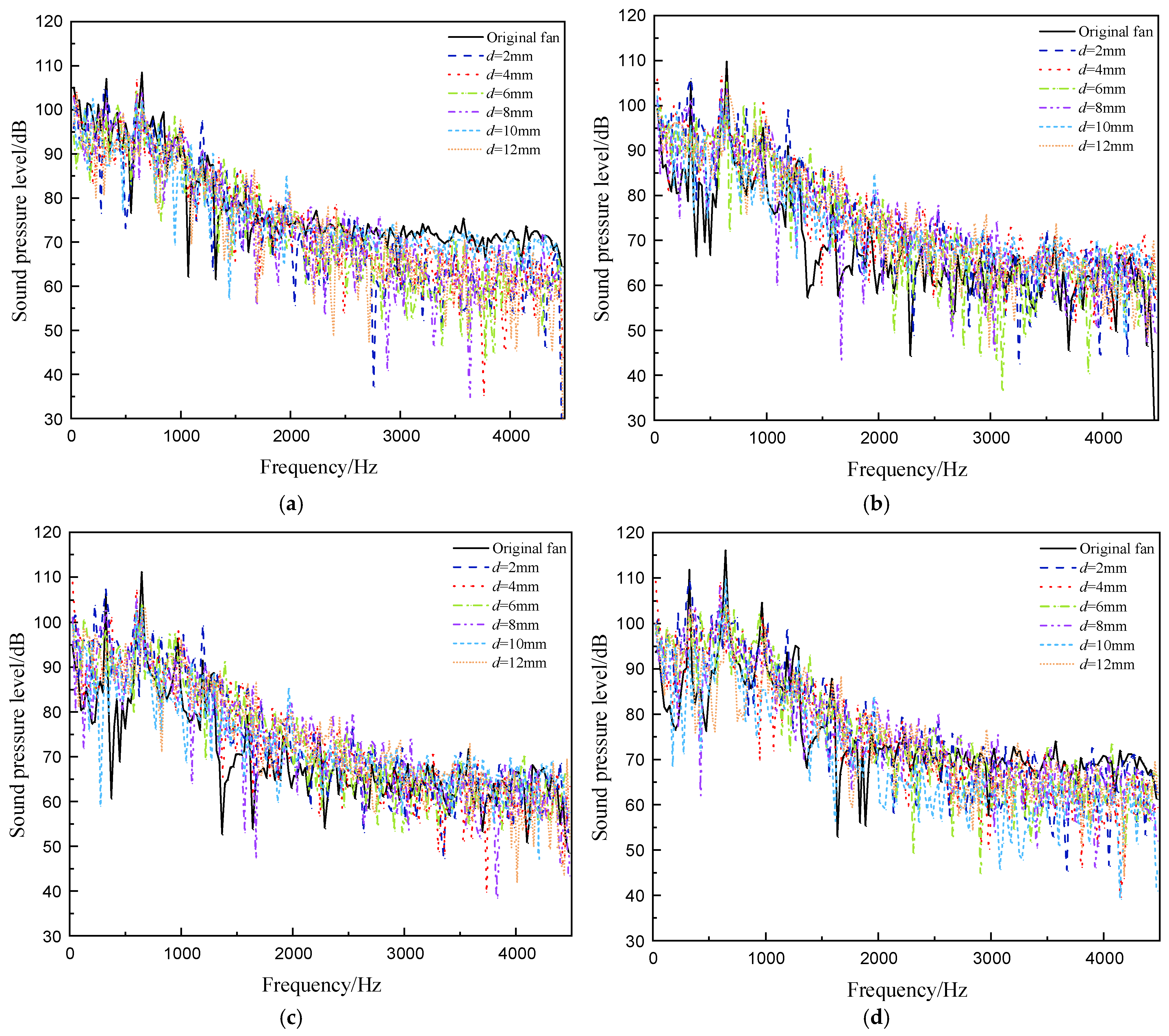
Figure 12.
Vortex identification diagram of Q Criterion for (a) the original fan, (b) d=2mm, (c) d=4mm, (d) d=6mm, (e) d=8mm, (d) d=10mm and (g) d=12mm fan models under design flow rate.
Figure 12.
Vortex identification diagram of Q Criterion for (a) the original fan, (b) d=2mm, (c) d=4mm, (d) d=6mm, (e) d=8mm, (d) d=10mm and (g) d=12mm fan models under design flow rate.
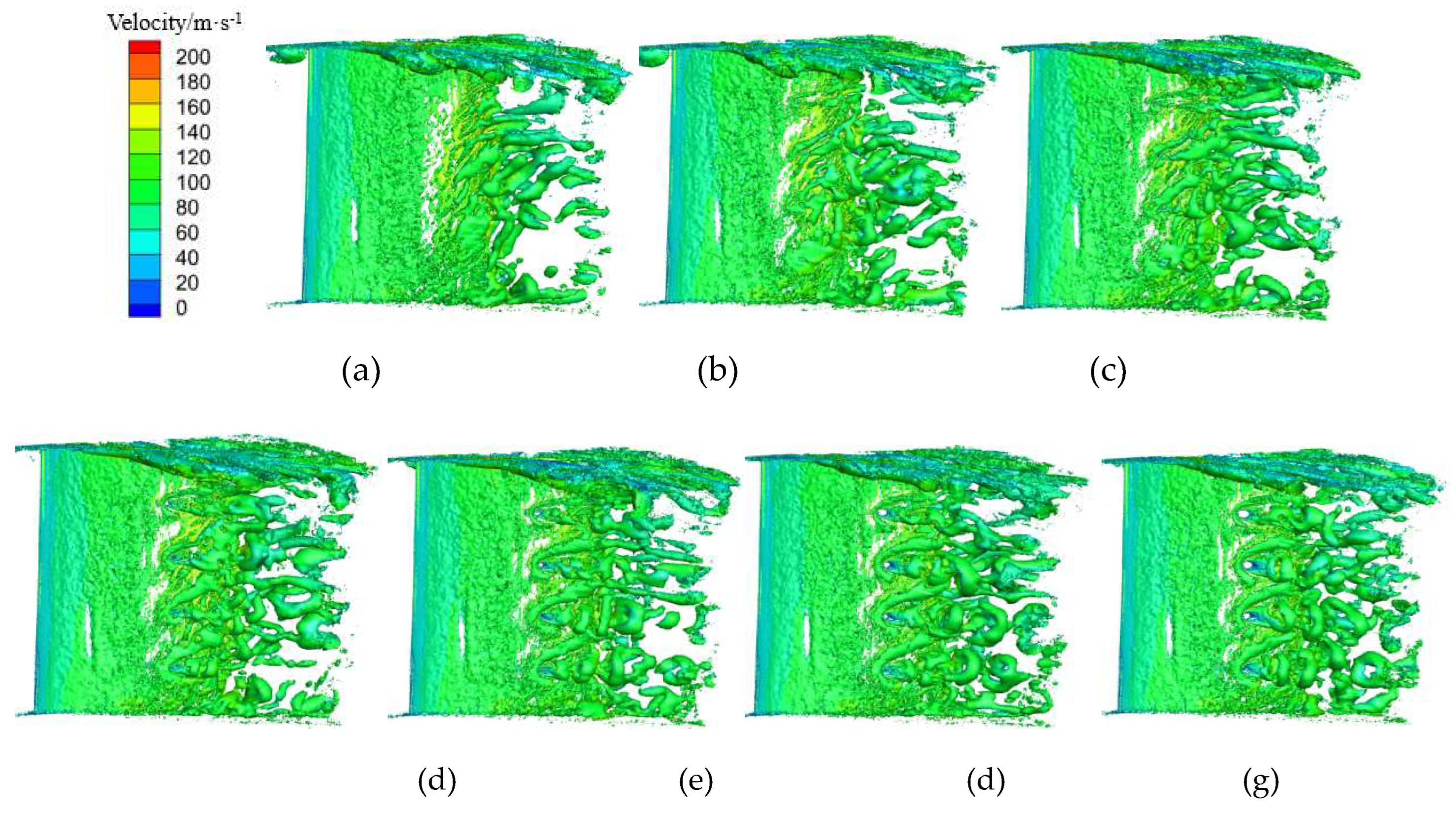
Figure 13.
Effect of the different stage blade perforating on (a) total pressure rise and (b) efficiency curves.
Figure 13.
Effect of the different stage blade perforating on (a) total pressure rise and (b) efficiency curves.

Figure 14.
Total SPL at monitoring points of (a) first-stage rotor and (b) second-stage rotor under design flow rate for different schemes.
Figure 14.
Total SPL at monitoring points of (a) first-stage rotor and (b) second-stage rotor under design flow rate for different schemes.
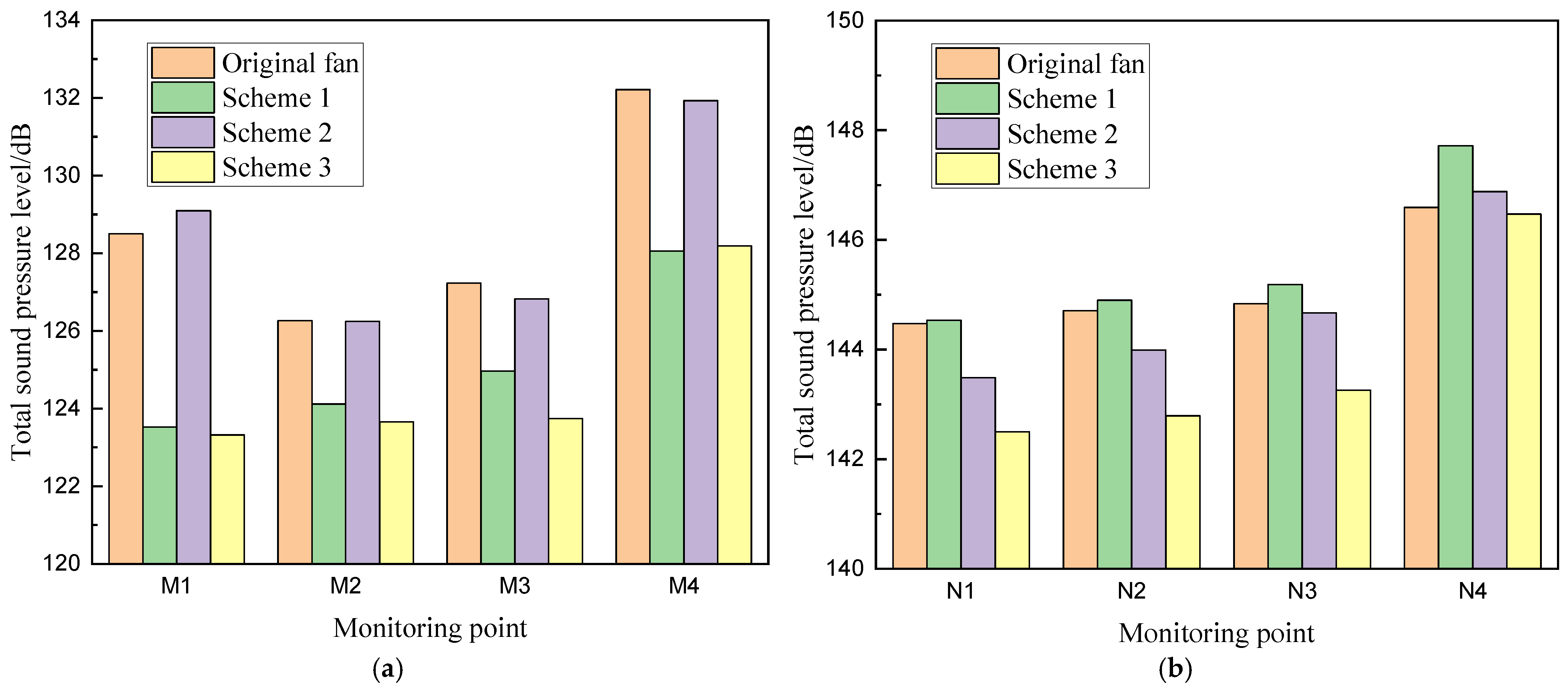

Table 1.
Main parameters and airfoil structural dimensions of the fan.
| Parameters | Values |
| Design total pressure rise/Pa | 11865 |
| Design efficiency/% | 88.3 |
| Design volumetric flow rate/m3·s-1 | 82.5 |
| Impeller diameter/mm | 1778 |
| Tip chord length of rotor blade/mm | 192 |
| Mid-span chord length of rotor blade/mm | 198 |
| Root chord length of rotor blade/mm | 202 |
| Tip setting angle of rotor blade/(°) | 31.7 |
| Mid-span setting angle of rotor blade /(°) | 39.1 |
| Root setting angle of rotor blade/(°) | 54.5 |
Disclaimer/Publisher’s Note: The statements, opinions and data contained in all publications are solely those of the individual author(s) and contributor(s) and not of MDPI and/or the editor(s). MDPI and/or the editor(s) disclaim responsibility for any injury to people or property resulting from any ideas, methods, instructions or products referred to in the content. |
© 2025 by the authors. Licensee MDPI, Basel, Switzerland. This article is an open access article distributed under the terms and conditions of the Creative Commons Attribution (CC BY) license (http://creativecommons.org/licenses/by/4.0/).
Copyright: This open access article is published under a Creative Commons CC BY 4.0 license, which permit the free download, distribution, and reuse, provided that the author and preprint are cited in any reuse.


