
Submitted:
06 March 2025
Posted:
07 March 2025
You are already at the latest version
Abstract
This study presents the fabrication and characterization of hybrid magneto-responsive composites (hMRCs), which are composed entirely of recyclable components: magnetite microparticles (MMPs) as fillers, lard as a natural binding matrix, and cotton fabric for structural reinforcement. MMPs are obtained by in-house plasma-synthesis, a sustainable, efficient, and highly tunable method for producing high-performance MMPs. The resulting hMRCs are integrated into flat capacitors, and their electrical capacitance (C), resistance (R), dielectric permittivity (ϵ′) and electrical conductivity (σ) are investigated under a static magnetic field, uniform force field and an alternating electric field. The experimental results reveal that the electrical properties of hMRCs are dependent on the volume fractions of MMPs and microfibers in the fabric, as well as the applied magnetic flux density (B) and compression forces (F). C shows an increase with both B and F, while R decreases due to improved conductive pathways formed by alignment of MMPs. σ is found to be highly tunable, with increases of up to 450 % under combined field effects. In the same conditions, C increases up to 60 %, and R decreases up to 80 %. Thus, by employing plasma-synthesized MMPs, and commercially available recyclable lard and cotton fabrics, this study demonstrates an eco-friendly, low-cost approach to designing multifunctional smart materials. The tunable electrical properties of hMRCs open new possibilities for adaptive sensors, energy storage devices, and magnetoelectric transducers.
Keywords:
Hybrid magneto-responsive composites
; Plasma-synthesized magnetite Microparticles
; Recyclable functional materials
; Tunable electrical properties
; Smart materials for sensing
1. Introduction
The increasing demand for smart multifunctional materials with adaptable physical properties has driven intense research in sensor technologies, flexible electronics and adaptive energy storage systems [1,2,3,4]. Among these, magneto-responsive materials are particularly promising due to their ability to modify mechanical and electrical properties in response to external stimuli, offering diverse applications in biomedical sensors [5], soft robotics [6], and active rheology control of cementious materials [7].
Conventional magnetorheological (MR) suspensions [8,9,10,11,12] and electrorheological (ER) fluids [13,14,15] have been widely investigated for their field-dependent behavior. Despite significant advancements in field-responsive materials, several critical challenges remain in designing materials that simultaneously achieve mechanical adaptability, electrical tunability, and environmental sustainability. Traditional MR and ER suspensions are inherently fluid-based, which introduces issues related to long-term stability, sedimentation, and the need for specialized containment systems [16,17,18]. These factors significantly limit their deployment in wearable electronics, flexible devices, and smart mechanical systems, where sustained performance over extended periods is essential. Furthermore, existing MR and ER materials typically respond to either magnetic or electric fields [19,20,21,22], with few exceptions in successfully combining both multi-field responsiveness and structural stability within a single material system [23,24,25,26,27].
Additionally, recyclability and sustainability remain overlooked aspects in the design of these materials. Most formulations rely on synthetic polymers and complex chemical binders, leading to environmental concerns regarding disposal and long-term ecological impact. The embedded microparticles, which determine the suspension’s responsiveness to external fields, are often produced through either chemical [28,29] or physico-chemical synthesis methods [30,31]. Chemical synthesis, although capable of creating dual-functional microparticles, is often hindered by the use of complex processes and environmentally hazardous reagents. Consequently, there has been a shift toward more sustainable alternatives, such as plasma-based physical synthesis [32,33,34,35] or green synthesis using waste natural materials [36,37]. These methods provide a scalable and eco-friendly approach for producing magnetite microparticles (MMPs) from recyclable materials, including onion, potato, tea, maringa and gaharu leafs, or carbon steel waste rods.
This study aims to overcome the environmental and technological challenges associated with traditional particle synthesis methods by developing multifunctional, stable and low-cost hybrid magneto-responsive composites (hMRCs) composed entirely of recyclable components. MMPs are synthesized through a plasma-based process that recycles carbon steel rods [38] used in civil constructions, reducing material waste and environmental impact. The composites use lard and cotton fabric as the matrix materials, both of which are commercially available and recyclable. Lard provides a stable, hydrophobic medium that reduces particle sedimentation and agglomeration due to its high viscosity and natural fat composition [39]. Its semi-solid state ensures even distribution of MMPs. When the mixture of lard and MMPs is soaked into cotton fabric, the MMPs are uniformly absorbed, creating magnetically responsive textiles with potential applications in wearable sensors, electromagnetic shielding, and protective gear. The lard also temporarily binds the particles to the fibers, enhancing particle adhesion and enabling further functionalization.
The primary objective is to investigate how these hMRCs respond to static magnetic fields and uniform compression, particularly in terms of their dielectric and electrical properties. The study also seeks to demonstrate the application of these hybrid materials in smart capacitors, evaluating their potential as field-responsive mechanical deformation sensors with adjustable sensitivity. By exploring the relationship between material composition, external fields, and electrical behavior, this work contributes to the development of sustainable, multifunctional materials for adaptive devices. These findings have potential applications in automotive sensors, wearable electronics, soft robotics, and energy storage systems, where tunable material properties are essential for performance optimization.
The remainder of this paper is organized as follows. Section 2 describes the materials and methods used to synthesize and characterize the hMRCs. Section 3 details the experimental results, focusing on the electrical properties of the fabricated capacitors and their responses to varying magnetic and mechanical field conditions. Section 4 presents an in-depth discussion of the results, emphasizing the physical mechanisms governing field-induced property changes. Finally, Conclusions section provides a summary of the key findings and their implications for future applications in smart and adaptive materials.
2. Materials and Methods
2.1. Materials
For the fabrication of hMRCs, the following materials are used: MMPs (see details in Appendix A), lard (from Elit, Alba Iulia, Romania) and cotton fabric.
The electrical properties of MMPs, lard and fabric are measured at a temperature of C using the flat capacitor (FC) method [25]. The results are summarized in Table 1 and show that all electrical properties are dependent on the nature of the materials used. This dependency arises from the formation of conductive nano-micro layers [23] by MMPs, between which oxides act as dielectric materials. These networks of microcapacitors result in an equivalent capacitance (C) and up to 2.58 times higher than that of lard.
However, the value of for the cotton fabric is much lower compared to that of MMPs and lard. The difference is due to the presence of air in the empty spaces between the fibers of the fabric. The table also shows that the of MMPs is approximately one order of magnitude higher than the values for both lard and cotton fabric. In the later case, the value of is determined by the moisture present in the cotton microfibers.
2.2. Preparation of MMPs + lard Mixture and hMRCs
2.3. Structural Properties of hMRCs
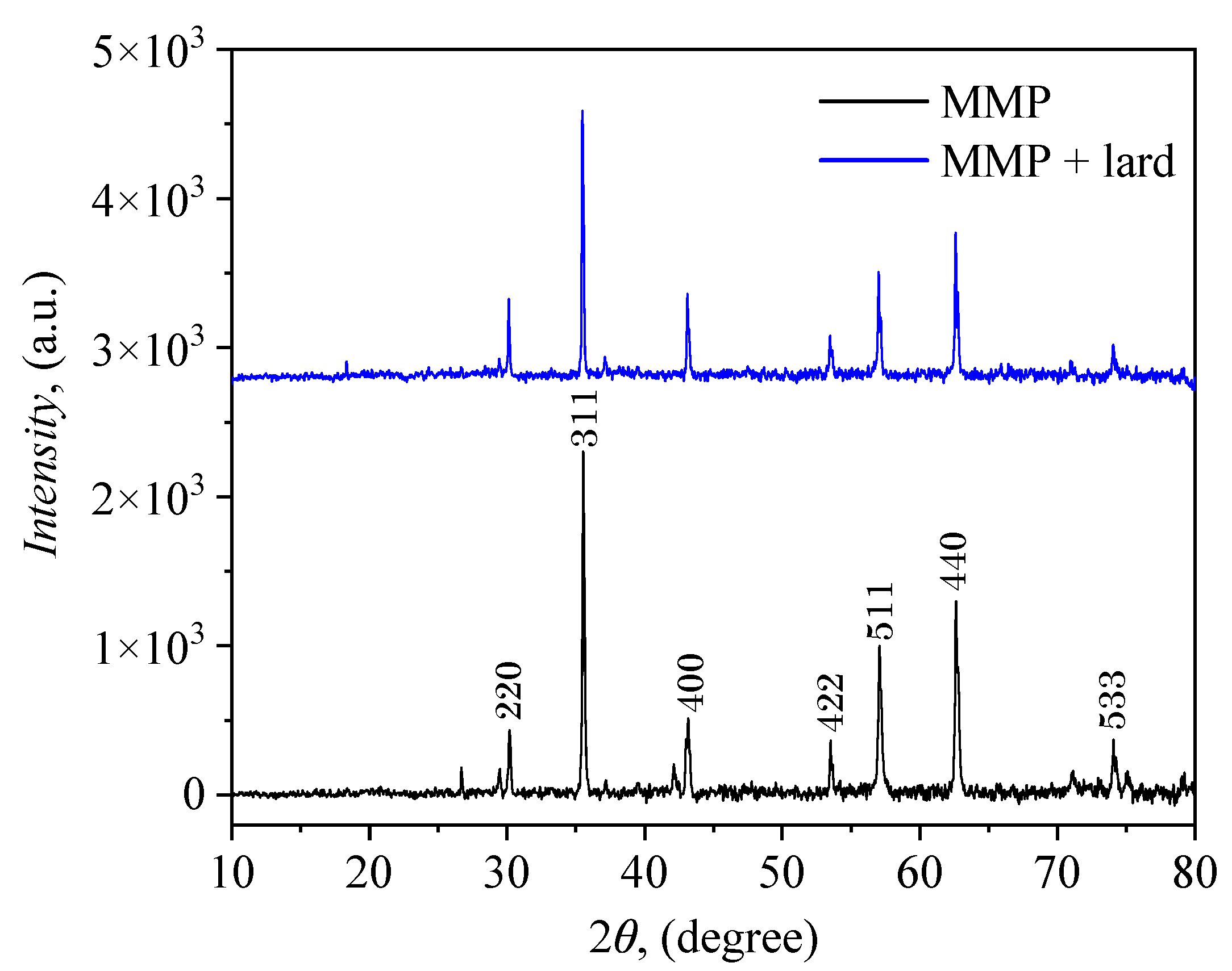
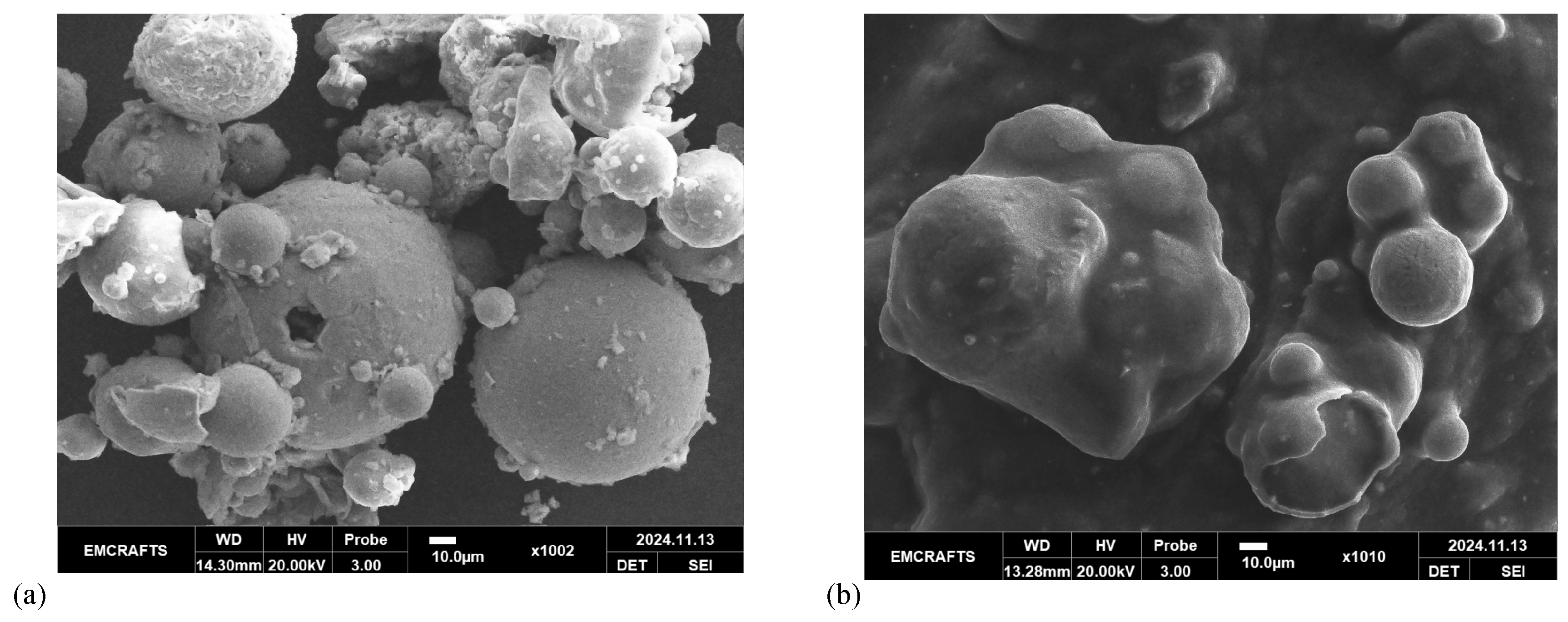
The crystalline structure, phase and morphology of and are studied using XRD and SEM techniques. XRD analysis confirmed the cubic magnetite phase in both and (Figure 2a). Differences in peak intensities suggest variations in crystallite size and phase interactions. SEM data (Figure 2b) show the presence of MMPs with dimensions ranging from few micrometers up to few hundred micrometers stuck to the cotton microfibers. This is facilitated by the presence of lard, which covers MMPs (Appendix B).
2.4. Magnetic Properties of hMRCs
The magnetization curves (Figure 3) are obtained by using an experimental setup described in Ref. [40]. The MMPs + lard mixture, which lacks the cotton matrix, displays magnetization levels between those of the hMRCs and MMPs. The lower magnetization of hMRCs (vs. MMPs) is due to the cotton matrix reducing particle alignment.
These magnetization properties play a critical role in the practical applications of hMRCs. For instance, the ability to adjust magnetization through matrix composition and magnetite content allows for tuning the sensitivity and responsiveness of mechanical sensors, such as strain or deformation sensors. The reduced coupling in fabric-embedded suspensions enhances stability under varying mechanical conditions, making them suitable for field-responsive materials in applications where precise control of rheological and magneto-mechanical behavior.
2.5. Manufacturing of FC
The manufacturing of FC is carried out using a strati-textolite (STP) with a thickness of 0.6 mm, WR-Type 611 (from Rademacher, Germania) and hMRCs. On one side of STP there is a thin copper layer. From the STP board, four pieces are cut, each one with dimensions 30 mm × 30 mm (Figure 4a). On each STP, two electrical conductors are welded with tin-lead alloy. and are fabricated by sandwiching , and respectively between the copper-coated plates (Figure 4b), with insulation tape applied (Figure 4c). Appendix C provides additional details on the components of FC.
2.6. Experimental Setup for Measuring the Electrical Properties of FC
The setup depicted in Figure 5 comprises an electromagnet, between the poles of which FCs are alternately inserted. The electromagnet is powered by a DC source (model RXN-3020D, manufactured by HAOXIN, China). The magnetic flux density B between the north (N) and south (S) poles is regulated by adjusting the electric current supplied to the electromagnet coil (pos. 2) through the DC source. A Hall probe (h; Gaussmeter DX-102, model DX-102, from DexingMagnet, China) was used to measure B. The capacitors and h, are secured by mechanical tensioning. This is achieved using a non-magnetic platform (not shown in Figure 5) and a non-magnetic shaft (pos. 3 in Figure 5). The mechanical tension exerted by the non-magnetic body on the surface of the capacitors is due to compression forces, which are increased in steps of 0.5 N within the interval from 0 to 3 N.
C and equivalent resistance (R) are measured using an RLC bridge Br (model CHY-41R, made in Taiwan). These measurements are taken while the capacitors are subjected to an alternating electric field of frequency kHz, superimposed with a magnetic field and uniformly applied compression forces F. The measured values are recorded after stabilization, i.e. after a time interval s following the application of B and F on the capacitors.
3. Electrical Properties of FC
The measurements of electrical properties are performed under the same conditions as those used for MMPs and lard, described in the Appendix D.
3.1. Electrical Capacitance and Resistance
C and R are measured in a static magnetic field superimposed on the static compressive force field. The static magnetic field is increased with a step of 10 mT, up to the maximum value of 150 mT. The variation of capacitance with B for different values of F, i.e. the function , is shown in Figure 6. Similarly, resistance , is shown in Figure 7.
The capacitance measurements reveal a clear dependence on both B and F. For the former case, the dependence is quasi-linear. For , at mT, C increases from 79 pF with no force to 94 pF when N. At mT, the capacitance rises to 97.2 pF without force and reaches 113 pF at N. Similarly, for , C starts at 103 pF with N and mT, increasing to 135 pF at N. At 150 mT, C ranges from 139 pF ( N) to 178 pF ( N). This demonstrates a higher overall capacitance and sensitivity for due to its increased magnetite content.
The combined effects of B and F enhance polarization within the suspensions. These changes suggest that by tuning the magnetic and mechanical parameters, the dielectric response of the capacitors can be precisely controlled. This tunability is advantageous for mechanical deformation sensors, where sensitivity to small force changes is critical. For instance, in , the capacitance increases by approximately 30 % with the application of a 3 N force at mT, compared to about 19 % in .
The resistance measurements for the capacitors demonstrate a strong dependence on both B and applied compression force. Resistance decreases quasi-linearly with increasing magnetic field for both suspensions, indicating that the alignment of magnetite particles under the magnetic field enhances conductive pathways within the hybrid matrix. This effect is further amplified by compression forces, which improve particle contact and reduce insulating voids within the structure. For example, in , R drops from 6.321 M at mT and N to 4.625 M at N. Similarly, in , R decreases from 4.764 M to 2.82 M under the same conditions.
Comparing the two capacitors, exhibits lower resistance across all field conditions due to the higher volume fraction of magnetite in . The increased concentration of conductive particles reduces the effective resistivity of the material by enhancing the density of current pathways. This behavior also suggests that is more responsive to both mechanical and magnetic field inputs, as the conductive network becomes more stable and efficient under combined field conditions.
3.2. Relative Dielectric Permittivity
From the formula of the parallel-plate capacitor, the relative dielectric permittivity is obtained as , where is the distance between the plates of the capacitor, pF/m is the vacuum permittivity, and S is the area of the common surface of the plates of the capacitor. For the FC with MMPs and lard the numerical values used here are m and . Thus, can be written as:
For MMPs, lard, and cotton fabric, they are quasi-constant, and the values are reported in Table 1 (together with the dielectric loss factor ).
For the capacitors with cotton fabric we have m and , and thus:
This shows that for the capacitors used, has identical shapes, with values shifted vertically downward by the corresponding coefficient. Thus, they also increase with both B and applied F due to enhanced polarization. These results indicate that magnetic and mechanical fields strongly influence the dielectric response of the suspensions.
3.3. Electrical Conductivity
Taking into account the expression of electrical conductivity () of a linear resistor, for hMRCs obtained here, it can be written as:
Using the same numerical values as in Section 3.1, Equation (3) becomes:
The results are plotted in Figure 8 and show that has a strong dependence on both B and F. increases with B due to improved alignment of magnetite particles. As above, compression forces further augment this effect by reducing insulating voids and increasing particle-particle contact efficiency, thereby improving the overall conductivity.
A comparison between and highlights the impact of material composition on electrical properties. , with a higher MMPs content, exhibits significantly greater conductivity than across all field conditions.
3.4. Quantification of the Contribution of Magnetic and Compression Fields on C, R, and
The effects of magnetic and compression field on C, R and of hMRCs are quantified by the relation:
where is , or from Figure 6, Figure 7 and Figure 8, and are the corresponding value when neither magnetic nor compression fields are applied.
The quantification of the capacitance increase in capacitors (Figure 9a) and (Figure 9d) highlights the influence of both B and F. As the magnetic and compression fields increase, the C rises significantly, indicating enhanced polarization within the dielectric medium. , with a higher magnetite content, shows a more pronounced increase in C compared to .
The quantification of the resistance reduction for capacitors (Figure 9b) and (Figure 9e) complements the capacitance analysis, highlighting the influence of both B and F on . For example, at mT and N, shows a resistance reduction of approximately 27 %, while exhibits a more substantial reduction of over 40 %. At higher B (e.g., 150 mT), the reductions reach 54.7 % and 81.7 % for and , respectively. These reductions correspond to increases of around 120 % for (Figure 9c) and nearly 450 % for (Figure 9f), highlighting the significant impact of the combined magnetic and mechanical fields on enhancing material conductivity. Unlike conventional MR suspensions, which exhibit little to no change in electrical properties under a magnetic field, these changes indicate that hMRCs can function as a field-responsive dielectric material, where both charge distribution and conductive pathways are modulated by external magnetic and mechanical stimuli.
These observations correlate with the capacitance data, where both polarization and conductivity improve under field-induced particle alignment and compression. The higher MMPs content in results in a more pronounced reduction in resistance, consistent with its larger capacitance increase under similar conditions.
4. Discussions
4.1. Scalability and Process Optimization of Plasma-Synthesized MMPs
The feasibility of scaling up plasma-based synthesis is a crucial consideration for industrial adoption [38,41]. The method used in this study, which involves plasma arc pulverization of carbon steel rods [38], offers several advantages over conventional chemical synthesis routes, particularly in terms of sustainability and material recycling. One of the major advantages is its ability to instantaneously generate high-purity MMPs from waste materials without the need for extensive purification steps. This is particularly beneficial in industrial applications where large-scale production of magnetically responsive materials is required, such as in adaptive sensors, flexible electronics, and magnetoelectric transducers [42]. However, compared to conventional chemical precipitation or sol-gel methods, the plasma process requires a high initial energy input [43] to maintain the plasma arc, which could be a limiting factor for widespread commercial use.
Thus, to enhance scalability and process efficiency, alternative synthesis environments can being considered. One approach involves obtaining microparticles in an inert environment, such as argon, which prevents unwanted oxidation but does not actively reduce species. A more effective method could involve using a mixture of argon with reducing gases such as hydrogen or ammonia, which would help protect the MMPs from oxidation and stabilize the magnetite phase. Additionally, collection of microparticles in protective liquid matrices, such as mineral oils combined with inert or reducing gas environments, could further prevent oxidation and allow for immediate integration into liquid-based magnetorheological fluids or suspensions. These modifications could significantly improve the efficiency of plasma synthesis while maintaining high product quality, making the technique more viable for industrial applications.
The integration of these protective environments into the plasma-based synthesis process can improve the stability and yield of MMPs while simultaneously enhancing the scalability of the technique. By further optimizing plasma arc parameters, such as discharge current and feed rate, it may be possible to reduce energy consumption while maintaining high production yields. The adaptability of the plasma approach to different gas environments and collection methods underscores its potential as a scalable and sustainable alternative to traditional magnetite synthesis techniques.
4.2. Comparison with Conventional ER/MR materials
A significant advantage of hMRCs over traditional MR and ER suspensions is their ability to simultaneously respond to both magnetic and mechanical fields while maintaining structural stability. Conventional MR and ER fluids are widely used in adaptive damping systems, vibration control devices, and active rheology applications, where an external magnetic or electric field induces viscosity changes. However, these suspensions typically face two major challenges: (i) sedimentation instability due to density mismatches between the magnetic/dielectric particles and the carrier fluid, and (ii) limited tunability in response to external fields [44]. MR fluids, for instance, are primarily responsive to magnetic fields, whereas ER fluids require high external voltages (often exceeding 3 kV/mm), making them energy-intensive and less practical for certain applications.
In contrast, the hMRCs obtained here offer improved structural stability due to their solid-state composition, where MMPs are embedded within a natural lard matrix and reinforced with cotton fabric. This design mitigates sedimentation issues commonly associated with MR suspensions and eliminates the need for specialized containment systems. Furthermore, the ability of hMRCs to modulate their electrical properties (capacitance, resistance, and conductivity) under simultaneous magnetic and mechanical stimuli distinguishes them from conventional MR/ER materials, which typically exhibit limited electrical property variations under field exposure. The strong increase in conductivity (up to 450 %) and capacitance (up to 60 %) under external fields suggests that hMRCs could be a viable alternative for adaptive electronic components, where field-controlled electrical properties are required.
The 450 % increase in electrical conductivity observed in the hMRCs can be attributed to a complex interplay of microstructural and electronic effects. A primary mechanism involves the field-induced alignment of MMPs, which enhances percolation pathways for charge transport. Under an applied magnetic field, dipolar interactions between MMPs facilitate their reorientation and chaining along field lines, reducing interparticle distances and forming more efficient conductive paths. This effect is further amplified by mechanical compression, which reduces air gaps and contact resistance between particles, allowing for improved charge transfer. Additionally, the soft, viscoelastic nature of the lard matrix enables localized deformation under pressure, leading to better interfacial connectivity between conductive particles.
Beyond structural reorganization, several electronic transport mechanisms also contribute to the conductivity enhancement. Field-controlled dielectric breakdown within the lard matrix may occur, wherein applied fields induce polarization of molecular components, reducing resistivity in localized regions. Furthermore, magnetostriction-induced microstructural rearrangements may lead to dynamic changes in particle distribution, enhancing connectivity. In nanoscale junctions, quantum tunneling effects could also play a role, particularly under strong compression, where the narrowing of insulating barriers facilitates electron transport. The combination of these factors, i.e. particle alignment, contact resistance suppression, dielectric modifications, and tunneling contributions, explains the highly tunable electrical response of hMRCs, making them a promising class of materials for adaptive electronic components and magnetoelectric applications.
From an application perspective, the ability of hMRCs to function as mechanical deformation sensors, tunable capacitors, and adaptive resistors expands their potential use beyond traditional MR/ER applications. While MR suspensions are mainly limited to mechanical damping and actuation, and ER suspensions require high electric fields, hMRCs provide a field-controlled tunable dielectric response, making them suitable for magnetoelectric transducers, wearable electronics, and electromagnetic shielding. These multifunctional properties place hMRCs in a unique category of smart materials that bridge the gap between MR/ER fluids and solid-state adaptive electronic materials.
4.3. Future Directions for Large-Scale Implementations
To bridge also the gap between laboratory-scale development and industrial application, future research should focus on refining the plasma-based synthesis method to further enhance its industrial scalability. This includes optimizing the plasma arc parameters to reduce energy consumption while maintaining high production yields and investigating alternative methods for controlling particle size distribution. The incorporation of protective environments should be systematically studied to determine their effects on particle stability and magnetic properties. Additionally, long-term mechanical and electrical stability testing under real-world conditions will be necessary to validate the practical applicability of these materials in commercial devices.
By addressing these challenges, plasma-based synthesis could become a key enabling technology for the large-scale production of advanced magneto-responsive composites. Further collaborations with industrial partners will be essential to optimize manufacturing conditions and to explore integration strategies for these composites in existing production lines. The potential for waste material utilization and sustainable material design makes this approach highly relevant for industries seeking eco-friendly solutions for high-performance functional materials.
Conclusions
This study successfully developed hMRCs using recyclable cotton fabric, lard, and MMPs synthesized from recycled carbon steel rods through an argon plasma process. The electrical properties of these hybrid composites are systematically investigated using capacitors subjected to an alternating electric field (f = 1 kHz), a static magnetic field, and uniform compression forces.
The experimental results demonstrate that the relative dielectric permittivity and electrical conductivity of hMRCs can be effectively controlled by adjusting the volume fraction of MMPs. Additionally, the application of static magnetic fields and compressive forces significantly influences the capacitive and resistive responses of the capacitors. The findings indicate that these devices can function as mechanical sensors with tunable sensitivity, where the degree of mechanical deformation detection can be modulated via an external magnetic field.
Furthermore, the ability to fine-tune dielectric permittivity and electrical conductivity at low compression forces highlights the potential of these materials for applications in adaptive sensing, energy storage, and magnetoelectric transducers. By employing sustainable and low-cost materials, this work contributes to the development of environmentally friendly multifunctional materials. Future work will focus on scaling up production and integrating hMRCs into real-world devices for industrial testing and commercialization.
Author Contributions
Conceptualization, I.B. and E.M.A.; methodology, I.B. and E.M.A; validation, I.B., E.M.A., P.S., L.C. and A.M.G.; formal analysis, I.B., E.M.A., P.S., L.C. and A.M.G.; investigation, I.B. and E.M.A.; writing—original draft preparation, I.B. and E.M.A.; writing—review and editing, I.B. and E.M.A.; visualization, E.M.A.; supervision, I.B.; All authors have read and agreed to the published version of the manuscript.
Funding
Ioan Bica acknowledges financial support from the National Council for Scientific Research in Higher Education of Romania (CNCSIS), grant 1382, type A.
Institutional Review Board Statement
Not applicable.
Informed Consent Statement
Not applicable.
Data Availability Statement
The original contributions presented in the study are included in the article/supplementary material, further inquiries can be directed to the corresponding author/s.
Conflicts of Interest
The authors declare no conflicts of interest.
Appendix A. Setup for Producing MMPs
The setups for generation of the argon plasma jet (ArPJ) and argon plasma arc (ArPA) have the configuration shown in Figure A1(a), and respectively in Figure A1(b). They include the plasma generator (PG), the argon supply and flow regulation system (APF), the direct current power source (PS), and a system for positioning and adjusting the rod feed rate in the plasma (SPARP). The PG generator includes the thoriated tungsten electrode (TTE) and the water-cooled nozzle (NZ).
The APF system includes an argon cylinder, bottled at a pressure of 150 bar, equipped with a pressure regulator and a flowmeter. The PS source has a no-load voltage of and a falling volt-ampere characteristic. The SPARP system allows for up-down adjustment of the position of the PG relative to an electrode rod (ERod), made of carbon steel, as well as continuous adjustment of the rod feed speed into the plasma.
Figure A1.
(a) Schematic representation of the experimental setup for obtaining MMPs. (a) Generation of ArPJ. (b) Generation of ArPA. APF - argon cylinder under pressure, NZ - nozzle, TTE - thorium tungsten electrode, Ar - Argon, K - electric contactor, PS - DC power supply, R - electric current limiting resistor, PG - plasma generator with TTE and NZ, - nozzle-to-rod distance, MD - metal droplets, ERod - the rod, SPARP - system for positioning and advancing the rod into the plasma, - velocity of ER rod, - axial velocity of the plasma jet, Ox and Oz - coordinate axes.
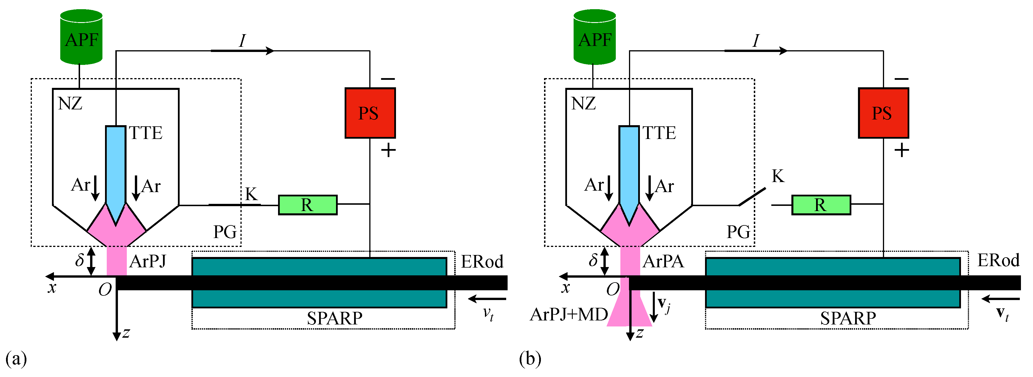
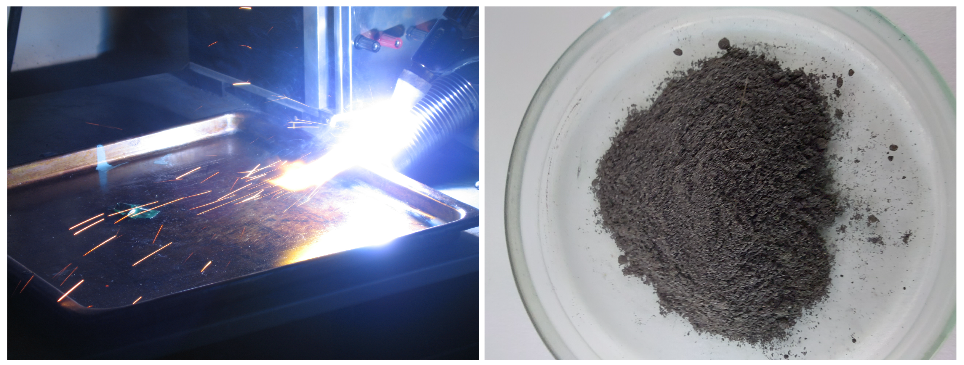
To obtain the MMPs, the following steps are performed. The argon flow rate is adjusted to specific values. The plasma jet is ignited by connecting the PS source to the PG generator and applying a high-frequency voltage between the TTE and NZ electrodes. This results in the formation of the ArPJ (Figure A2 - Left panel), sustained by a current whose intensity is limited by a resistor. At the moment ArPJ forms, the contact K opens, transferring the ArPA to the ERod. At that point, the ERod begins linear motion at pre-set speeds . Instantly, the ERod is transformed into metal vapor carried by the ArPJ (Figure A2 - Left panel). The plasma is generated at a discharge current of intensity . This corresponds to a power density ranging between 945 and . Under these conditions, a steel rod with a diameter of 3 mm, introduced into the plasma at a speed mm/s is instantly pulverized (Figure A2 - Left panel). The number of droplets per second, along the discharge axis , is between and . The MMPs (Figure A2 - Right panel) are obtained through vapor condensation and droplet formation at ambient temperature.
Figure A2.
(Left panel). Visualization of argon plasma mixed with metal droplets (MD): the intensely bright region is the ArPJ, while the bright lines show an instance of the trajectory of MD. (Right panel) Resulted MMPs placed in a Petri dish.
Figure A2.
(Left panel). Visualization of argon plasma mixed with metal droplets (MD): the intensely bright region is the ArPJ, while the bright lines show an instance of the trajectory of MD. (Right panel) Resulted MMPs placed in a Petri dish.
Appendix B. XRD and SEM Measurements
The crystalline structure and phase of MMPs with and without and lard, were studied using a PANalytical X’Pert Pro MPD diffractometer with Cu-K radiation (). Data were collected in the range from to with a collection time of 0.2 seconds per step.
The standard Rietveld technique using the FullProf program was applied for refinement and the structural parameters of the composites were calculated. The analysis of the diffraction spectra (Figure A3) shows that the position of the peaks of the diffractogram correspond to the phase identified according to the cubic space group Fd-3m of magnetite, according to the JCPDS card number: 01–088–0315. The major crystallographic peaks at diffraction angles , corresponding to the (220), (311), (400), (422), (511), (440) and (533) reflections of magnetite.
Figure A3.
XRD data for MMPs, without and with lard.
The surface morphological analysis of the MMPs without and with lard is studied by SEM (Figure A4). The composites were analyzed using the following working parameters: acceleration voltage of 30 kV, spot value of 3, magnification of 3000 x, in high vacuum mode. Thus, the qualitative analysis of materials based on shows that the particles have a spherical shape, with dimensions of several tens of micrometers, which is in accordance with the results obtained by X-ray diffraction. In the case of the magnetite-lard compound, the SEM images have highlighted the fact that the magnetite particles are embedded in the lard.
Figure A4.
SEM images of MMPs, without lard (a), and with lard (b).
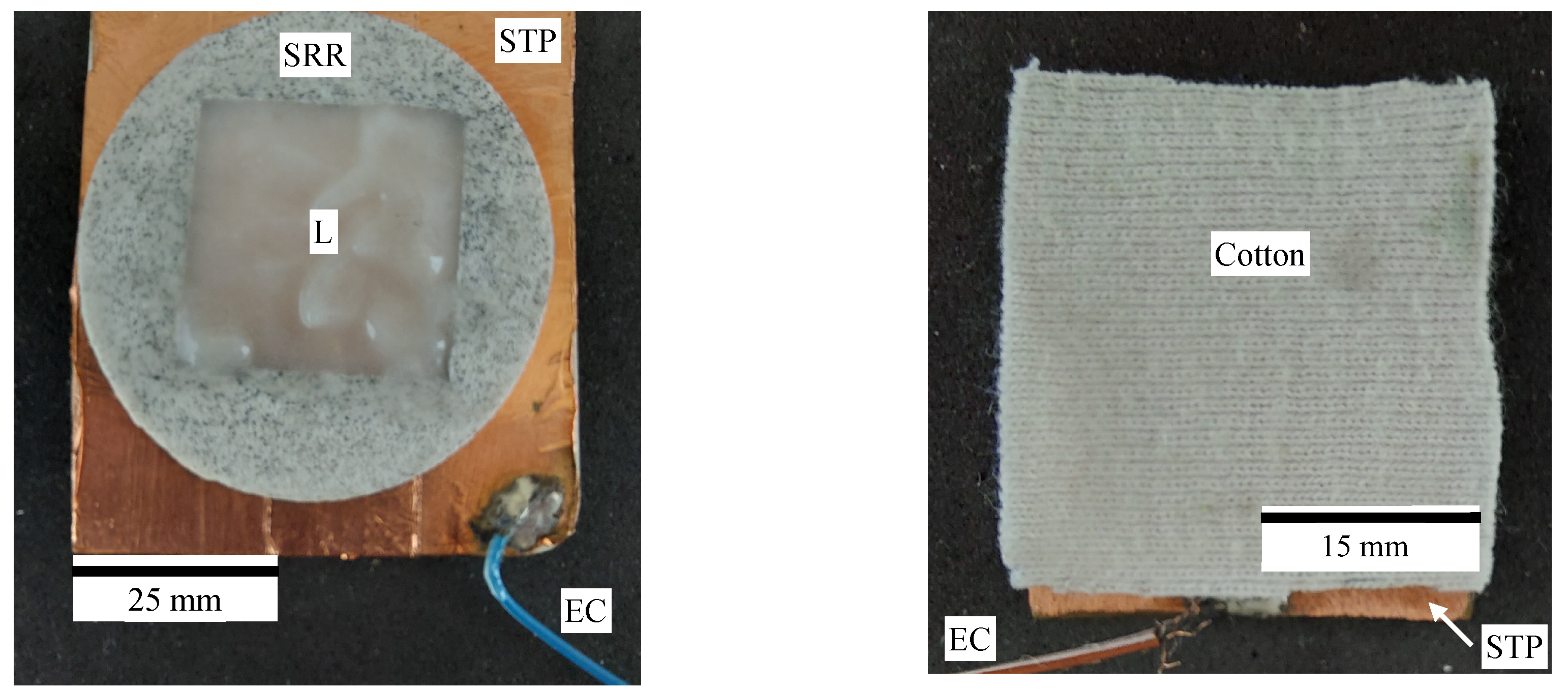
Appendix C. Components of FC
We use the measurement cell shown in Figure A5 (Left panel). These are made up of two stratified textolite plates STP, as described in Section 2.5. On a STP plate, a silicone rubber ring (SRR) with a square cavity inside is fixed. In this cavity, MMPs and lard are alternately introduced, over which the second STP plate with the copper side is pressed. The resulting assembly is consolidated with an insulating adhesive tape produced by 3M (USA).
When MMPs are used, the resulting assembly is a flat capacitor. When lard is used, a second flat capacitor is obtained, denoted as . A third capacitor is obtained when, instead of the SRR with MMPs or lard, we use only a cotton fabric, as shown in Figure A5 (Right panel).
Figure A5.
Measuring cell (without top stratitextolite STP) used for electrical measurements. (Left panel) With lard. When MMPs are used, they replace lard from within the SRR. (Right panel) With cotton fabric. SRR - silicone rubber ring, EC - electrical connector.
Figure A5.
Measuring cell (without top stratitextolite STP) used for electrical measurements. (Left panel) With lard. When MMPs are used, they replace lard from within the SRR. (Right panel) With cotton fabric. SRR - silicone rubber ring, EC - electrical connector.
Appendix D. Measurement of Electrical Properties
For measurements of the electrical properties of MMPs and lard, we use the measurement cell shown in Figure A5 (Left part). Alternatively, for cotton fabric, the measurement cell from Figure A5 (Right part) is utilized. The experimental setup used is described in Section 2.6.
The capacitors are sequentially placed between the N and S poles of the electromagnet. By adjusting the intensity of the electric current supplied to the electromagnet coil, the magnetic field is set to achieve specific values mT ± mT.
The assembly, consisting of the FC and Hall probe h, is secured by applying a non-magnetic mass to the platform mounted on axis 3, as shown in Figure 6, creating a compressive force N. Using the Br bridge, model CHY-41R (made in Taiwan), measurements are taken at a frequency of kHz and at a specified voltage to determine C and the dielectric loss coefficient D. The measured values are presented in Table 1.
References
- Yildirim, M.; Candan, Z. Smart materials: The next generation in science and engineering. Mater. Today 2023. [Google Scholar] [CrossRef]
- Wang, B.; Lee, T.L.; Qin, Y. Advances in Smart Materials and Structures. Materials 2023, 16. [Google Scholar] [CrossRef]
- Wang, W.; Xiang, Y.; Yu, J.; Yang, L. Development and Prospect of Smart Materials and Structures for Aerospace Sensing Systems and Applications. Sensors 2023, 23. [Google Scholar] [CrossRef]
- Xu, J.; Jiang, Y.; Chen, X.; Tang, Z.; Gao, Y.; Huang, M.; Wan, Y.; Cheng, P.; Wang, G. Photo- and magneto-responsive highly graphitized carbon based phase change composites for energy conversion and storage. Mater. Today Nano 2022, 19, 100234. [Google Scholar] [CrossRef]
- Ding, H.; Hao, L.; Mao, H. Magneto-responsive biocomposites in wound healing: from characteristics to functions. J. Mater. Chem. B 2024, 12, 7463–7479. [Google Scholar] [CrossRef]
- Taccola, S.; Bakhshi, H.; Sanchez Sifuentes, M.; Lloyd, P.; Tinsley, L.J.; Macdonald, J.; Bacchetti, A.; Cespedes, O.; Chandler, J.H.; Valdastri, P.; et al. Dual-Material Aerosol Jet Printing of Magneto-Responsive Polymers with In-Process Tailorable Composition for Small-Scale Soft Robotics. Adv. Mater. Technol. 2024, 9, 2400463. [Google Scholar] [CrossRef]
- Zhang, Y.; Lesage, K.; Zhang, Y.; Tao, Y.; Van Tittelboom, K.; De Schutter, G. A comparison of magneto-responsive particles and testing protocols for active rheology control of cementitious materials. Cem. Concr. Compos. 2024, 146, 105390. [Google Scholar] [CrossRef]
- Bica, I.; Liu, Y.D.; Choi, H.J. Physical characteristics of magnetorheological suspensions and their applications. J. Ind. Eng. Chem 2013, 19, 394–406. [Google Scholar] [CrossRef]
- Han, S.; Choi, J.; Seo, Y.P.; Park, I.J.; Choi, H.J.; Seo, Y. High-Performance Magnetorheological Suspensions of Pickering-Emulsion-Polymerized Polystyrene/Fe3O4 Particles with Enhanced Stability. Langmuir 2018, 34, 2807–2814. [Google Scholar] [CrossRef]
- Kuznetsov, N.; Kovaleva, V.; Belousov, S.; Chvalun, S. Electrorheological fluids: from historical retrospective to recent trends. Mater. Today Chem. 2022, 26, 101066. [Google Scholar] [CrossRef]
- Yuan, J.; Hu, X.; Zhao, X.; Yin, J. Electrorheological Effect of Suspensions of Polyaniline Nanoparticles with Different Morphologies. Polymers 2023, 15. [Google Scholar] [CrossRef] [PubMed]
- Bunoiu, O.M.; Bica, I.; Anitas, E.M.; Chirigiu, L.M.E. Magnetodielectric and Rheological Effects in Magnetorheological Suspensions Based on Lard, Gelatin and Carbonyl Iron Microparticles. Materials 2024, 17. [Google Scholar] [CrossRef]
- Liang, Y.; Yuan, X.; Wang, L.; Zhou, X.; Ren, X.; Huang, Y.; Zhang, M.; Wu, J.; Wen, W. Highly stable and efficient electrorheological suspensions with hydrophobic interaction. J. Colloid Interface Sci. 2020, 564, 381–391. [Google Scholar] [CrossRef]
- Liu, X.; Song, H.; Sun, W.; Wang, B.; Zhang, P.; Yuan, X.; Wang, Z.; Li, X. Strong nano size effect of titanium silicalite (TS-1) zeolites for electrorheological fluid. Chem. Eng. J. 2020, 384, 123267. [Google Scholar] [CrossRef]
- Yang, J.; Ning, D.; Sun, S.; Zheng, J.; Lu, H.; Nakano, M.; Zhang, S.; Du, H.; Li, W. A semi-active suspension using a magnetorheological damper with nonlinear negative-stiffness component. Mech. Syst. Signal Process. 2021, 147, 107071. [Google Scholar] [CrossRef]
- Thiagarajan, S.; Koh, A.S. Performance and Stability of Magnetorheological Fluids—A Detailed Review of the State of the Art. Adv. Eng. Mater. 2021, 23, 2001458. [Google Scholar] [CrossRef]
- Kumar, S.; Sehgal, R.; Wani, M.; Sharma, M.D. Stabilization and tribological properties of magnetorheological (MR) fluids: A review. J. Magn. Magn. Mater. 2021, 538, 168295. [Google Scholar] [CrossRef]
- Choi, S.B. Sedimentation Stability of Magnetorheological Fluids: The State of the Art and Challenging Issues. Micromachines 2022, 13. [Google Scholar] [CrossRef]
- Tong, Y.; Li, X.; Zhao, P.; Dong, X.; Wu, Z.; Qi, M. Improved Magnetorheological Properties by Using Ionic Liquid as Carrier Liquid of Magnetorheological Fluids. Front. Mater. 2021, 8. [Google Scholar] [CrossRef]
- Xu, W.; Zhang, Z.; Liang, Z.; Tao, M.; Li, D. Rheological properties and suspension stability of magnetorheological fluid based on Fe3O4 hollow spheres. J. Magn. Magn. Mater. 2024, 589, 171227. [Google Scholar] [CrossRef]
- Erol, O.; Karatayeva, U.; Faul, C.F.J. Electrorheological Fluids Based on Porous Carboxyl-Functionalized Polytriphenylamines. ACS Appl. Polym. Mater. [CrossRef]
- Chen, L.; Ji, X.; Yan, H.; Wang, L.; Lin, Y.; Wang, B.; Hao, C. Preparation of layered carbon nitride/titanium-based metal skeleton materials and study on their electrorheological properties. Soft Matter 2025, 21, 87–99. [Google Scholar] [CrossRef]
- Anitas, E.M.; Munteanu, A.; Sedlacik, M.; Bica, I.; Munteanu, L.; Stejskal, J. Magnetic and electric effects in magnetorheological suspensions based on silicone oil and polypyrrole nanotubes decorated with magnetite nanoparticles. Results Phys. 2024, 61, 107768. [Google Scholar] [CrossRef]
- Bica, I.; Mircea Anitas, E.; Sedlacik, M.; Munteanu, A.; Munteanu, L.; Marina Elisabeth Chirigiu, L. Electrorheological and magnetorheological properties of liquid composites based on polypyrrole nanotubes/magnetite nanoparticles. Smart Mater. Struct. 2024, 33, 065007. [Google Scholar] [CrossRef]
- Bica, I.; Anitas, E.M.; Sedlacik, M.; Munteanu, A.; Munteanu, L.; Chirigiu, L.M.E.; Jurca, M. Electromagnetic modulation of conductance and susceptance in electrical devices based on silicone oil with polypyrrole–magnetite particle composites. J. Mater. Chem. C 2024, 12, 13596–13608. [Google Scholar] [CrossRef]
- Sun, Y.; Sang, M.; Xu, Y.; Zhang, Z.; Duan, S.; Wang, Y.; Gong, X. Conductive magnetorheological fluid (cMRF)-based flexible sensor with adjustable stiffness for magneto-mechanical dual-response and soft actuator. Chem. Eng. J. 2024, 489, 151229. [Google Scholar] [CrossRef]
- Alam, M.N.; Kumar, V.; Jo, C.R.; Ryu, S.R.; Lee, D.J.; Park, S.S. Mechanical and magneto-mechanical properties of styrene-butadiene-rubber-based magnetorheological elastomers conferred by novel filler-polymer interactions. Compos. Sci. Technol. 2022, 229, 109669. [Google Scholar] [CrossRef]
- Stejskal, J.; Sapurina, I.; Vilčáková, J.; Plachý, T.; Sedlačík, M.; Bubulinca, C.; Gořalík, M.; Trchová, M.; Kolská, Z.; Prokeš, J. Conducting and Magnetic Composites Polypyrrole Nanotubes/Magnetite Nanoparticles: Application in Magnetorheology. ACS Appl. Nano Mater. 2021, 4, 2247–2256. [Google Scholar] [CrossRef]
- Jurca, M.; Vilcakova, J.; Kazantseva, N.E.; Munteanu, A.; Munteanu, L.; Sedlacik, M.; Stejskal, J.; Trchova, M.; Prokes, J. Conducting and Magnetic Hybrid Polypyrrole/Nickel Composites and Their Application in Magnetorheology. Materials 2024, 17. [Google Scholar] [CrossRef]
- Pedroso-Santana, S.; Fleitas-Salazar, N. Ionotropic gelation method in the synthesis of nanoparticles/microparticles for biomedical purposes. Polym. Int. 2020, 69, 443–447. [Google Scholar] [CrossRef]
- Choudhury, N.; Meghwal, M.; Das, K. Microencapsulation: An overview on concepts, methods, properties and applications in foods. Food Front. 2021, 2, 426–442. [Google Scholar] [CrossRef]
- Bica, I.; Anitas, E.M.; Choi, H.J.; Sfirloaga, P. Microwave-assisted synthesis and characterization of iron oxide microfibers. J. Mater. Chem. C 2020, 8, 6159–6167. [Google Scholar] [CrossRef]
- Yu, J.; Wang, B.; Lu, Q.; Xiao, L.; Ma, X.; Feng, Y.; Qian, Y. Fabrication of Fe3O4 nanoparticles by using cathode glow discharge electrolysis plasma and its electrochemical properties. Electrochim. Acta 2022, 427, 140843. [Google Scholar] [CrossRef]
- Iovane, P.; Borriello, C.; Pandolfi, G.; Portofino, S.; Rametta, G.; Tammaro, L.; Fedele, N.; Galvagno, S. Thermal Plasma Spheroidization and Characterization of Stainless Steel Powders Using Direct Current Plasma Technology. Plasma 2024, 7, 76–90. [Google Scholar] [CrossRef]
- Navaneetha Pandiyaraj, K.; Karuppusamy, M.; Jayamurugan, P.; Chaturvedi Misra, V.; Ghorui, S.; Saravanan, P.; Nadagouda, M.N.; Unnikrishnan, B.; Gopinath, P.; Pichumani, M.; et al. Iron oxide nanoparticles (IONPs) synthesized via a novel non-thermal atmospheric pressure plasma-assisted electrolysis: Physicochemical characterization and cytocompatibility evaluation. Adv. Powder Technol. 2024, 35, 104441. [Google Scholar] [CrossRef]
- Ahmed, H.M.; El-khateeb, M.A.; Sobhy, N.A.; Hefny, M.M.; Abdel-Haleem, F.M. Green Synthesis of Magnetite Nanoparticles Using Waste Natural Materials and Its Application for Wastewater Treatment. Environ. Earth Sci. 2023, 25. [Google Scholar] [CrossRef]
- Sulistyaningsih, T.; Sari, D.A.; Widiarti, N.; Astuti, W.; Wulandari, R.; Harjunowibowo, D. Green synthesis of gaharu leaf extract-modified magnetite as an adsorbent for methyl orange textile dyes. Waste Management Bull. 2024, 2, 327–339. [Google Scholar] [CrossRef]
- Bica, I. Steady current plasma macro-nanotechnologies. J. Ind. Eng. Chem. 2009, 15, 304–315. [Google Scholar] [CrossRef]
- Zhang, L.; Zhang, K.; Yang, H.; Yue, K.; Liu, R.; Bi, Y.; Ma, C. Characterization of lard from different adipose tissues: Physicochemical properties, thermodynamics characteristics and crystallization behaviors. J. Food Compos. Anal. 2023, 115, 105021. [Google Scholar] [CrossRef]
- Ercuta, A. Sensitive AC Hysteresigraph of Extended Driving Field Capability. IEEE Trans. Instrum. Meas. 2020, 69, 1643–1651. [Google Scholar] [CrossRef]
- Navaneetha Pandiyaraj, K.; Karuppusamy, M.; Jayamurugan, P.; Chaturvedi Misra, V.; Ghorui, S.; Saravanan, P.; Nadagouda, M.N.; Unnikrishnan, B.; Gopinath, P.; Pichumani, M.; et al. Iron oxide nanoparticles (IONPs) synthesized via a novel non-thermal atmospheric pressure plasma-assisted electrolysis: Physicochemical characterization and cytocompatibility evaluation. Adv. Powder Technol. 2024, 35, 104441. [Google Scholar] [CrossRef]
- Yarali, E.; Baniasadi, M.; Zolfagharian, A.; Chavoshi, M.; Arefi, F.; Hossain, M.; Bastola, A.; Ansari, M.; Foyouzat, A.; Dabbagh, A.; et al. Magneto-/ electro-responsive polymers toward manufacturing, characterization, and biomedical/ soft robotic applications. Appl. Mater. Today 2022, 26, 101306. [Google Scholar] [CrossRef]
- Souza Filho, I.R.; Ma, Y.; Kulse, M.; Ponge, D.; Gault, B.; Springer, H.; Raabe, D. Sustainable steel through hydrogen plasma reduction of iron ore: Process, kinetics, microstructure, chemistry. Acta Mater. 2021, 213, 116971. [Google Scholar] [CrossRef]
- Tao, R. Electro-Rheological Fluids and Magneto-Rheological Suspensions; World Scientific, 2000. [CrossRef]
Figure 1.
Preparation of hMRCs. (a) MMPs + lard mixture. (b) Cotton fabric. (c) hMRC.
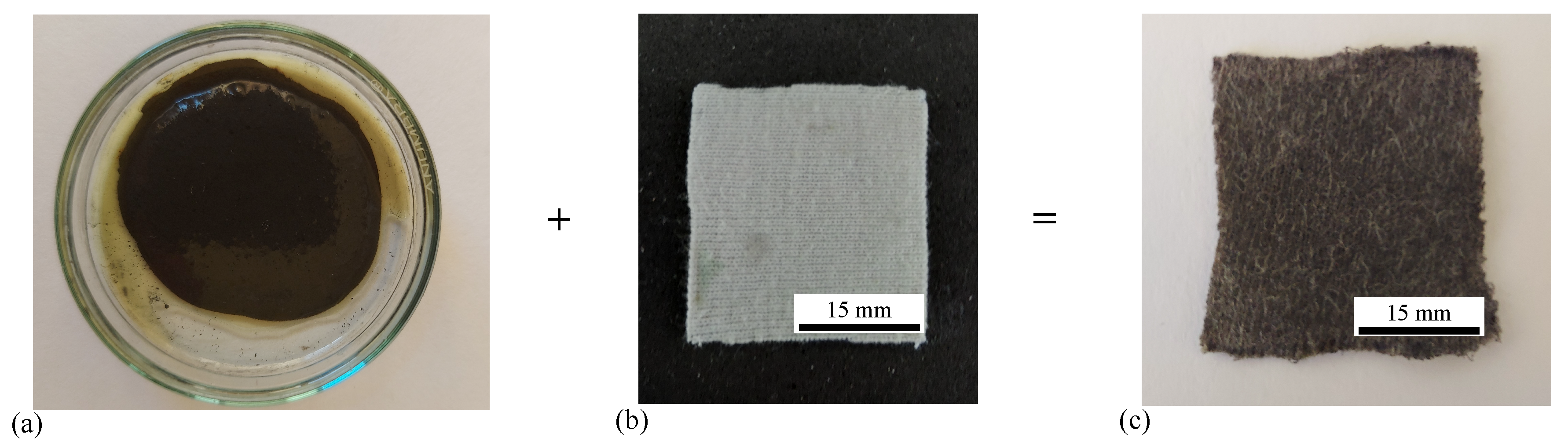
Figure 2.
(a) XRD diffraction from and . (b) SEM from . Spherical structures - MMPs; Elongated structures - cotton microfibers.
Figure 2.
(a) XRD diffraction from and . (b) SEM from . Spherical structures - MMPs; Elongated structures - cotton microfibers.
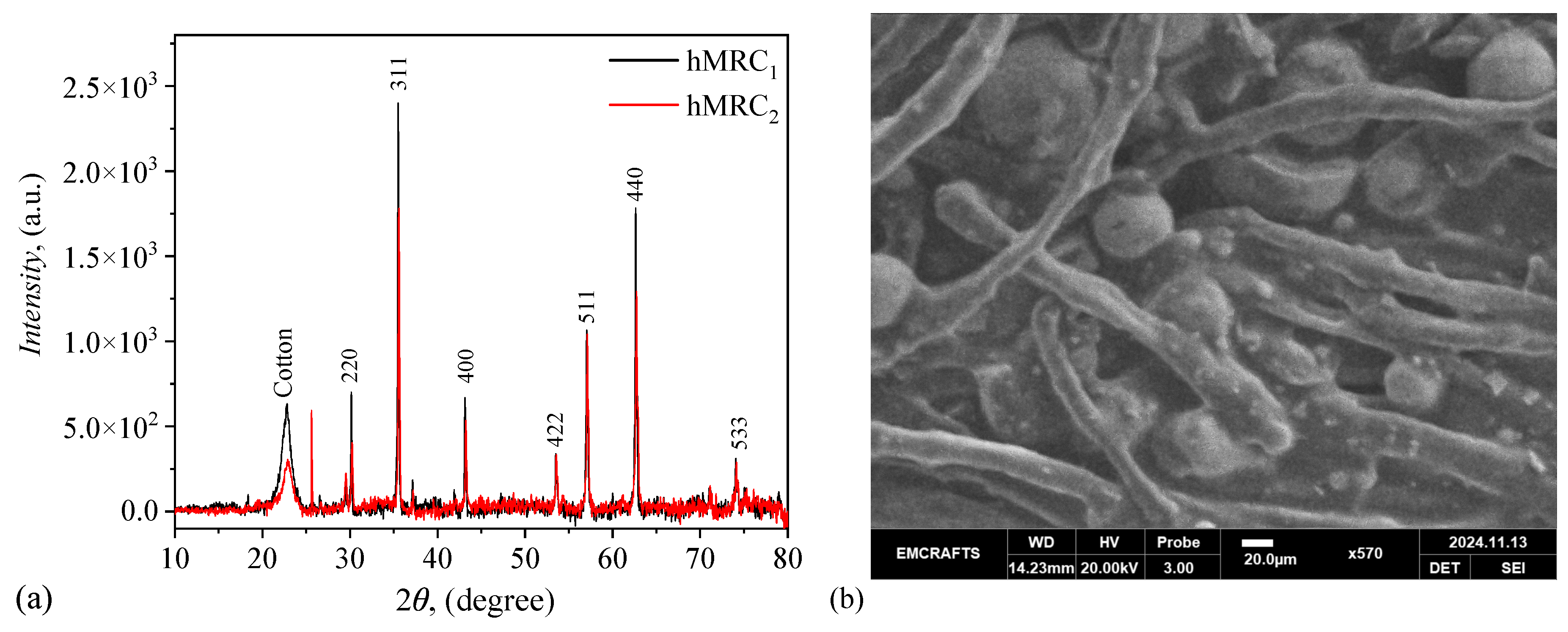
Figure 3.
Relative saturation magnetization for and , together with those of MMPs and MMPs + lard (for reference).
Figure 3.
Relative saturation magnetization for and , together with those of MMPs and MMPs + lard (for reference).
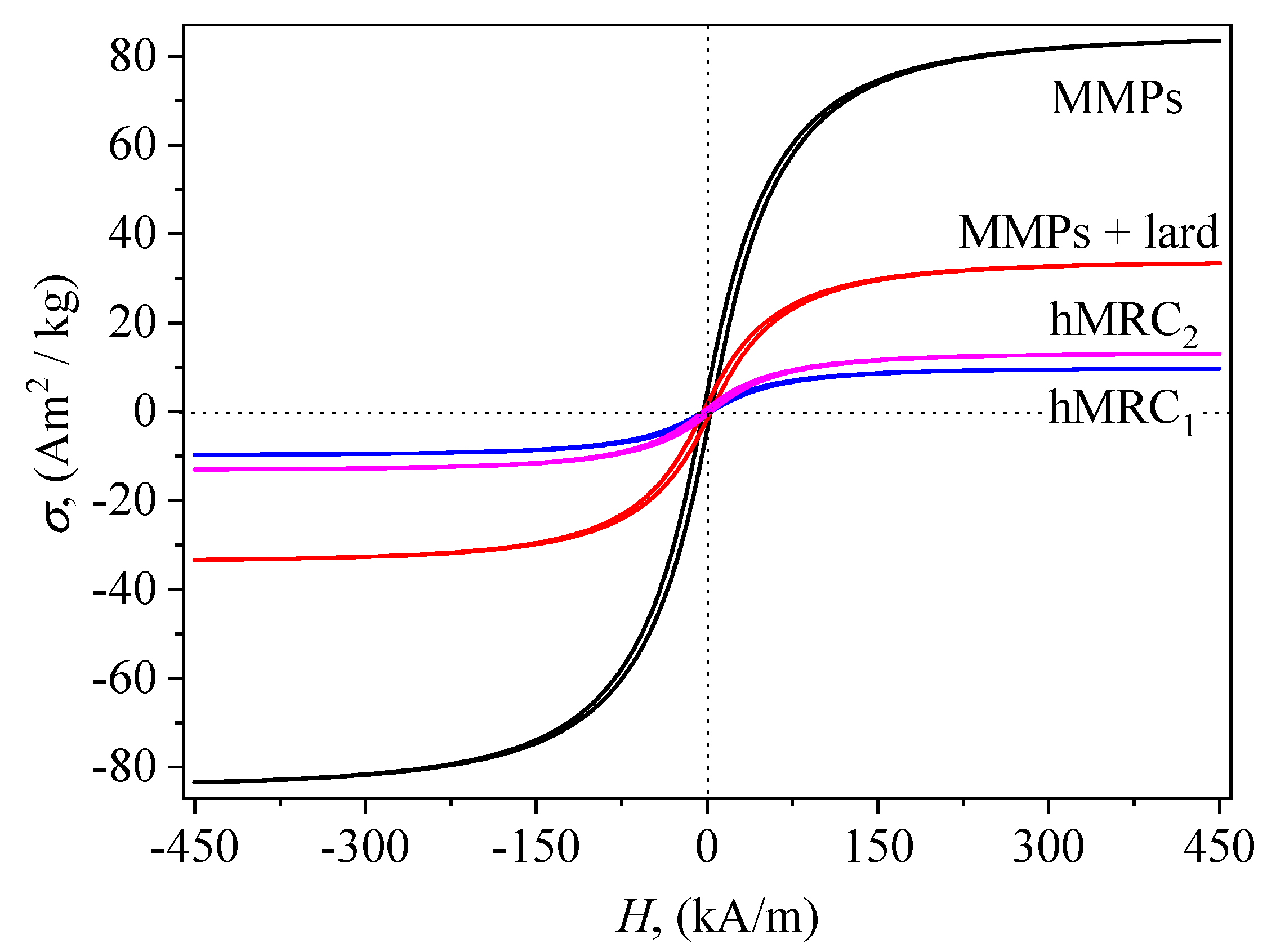
Figure 4.
Manufacturing of FC. (a) One STP welded with a conductor (top). (b) Two STPs with hMRC (black) between them. Each STP are welded with a conductor. (c) The resulting FC, covered with a self-adhesive insulating tape (white-gray).
Figure 4.
Manufacturing of FC. (a) One STP welded with a conductor (top). (b) Two STPs with hMRC (black) between them. Each STP are welded with a conductor. (c) The resulting FC, covered with a self-adhesive insulating tape (white-gray).
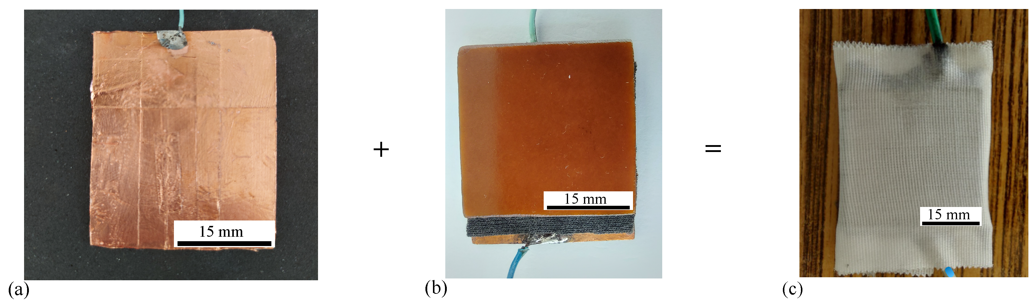
Figure 5.
Experimental setup (overall configuration) for measuring properties of FC: 1 - coil, 2 - magnetic yoke, 3 - non-magnetic shaft, N and S, magnetic poles, PS - DC power supply, Br - RLC bridge, Gs - gaussmeter, FC - flat capacitor, h - Hall probe, B - magnetic flux density vector, F uniform compressive force.
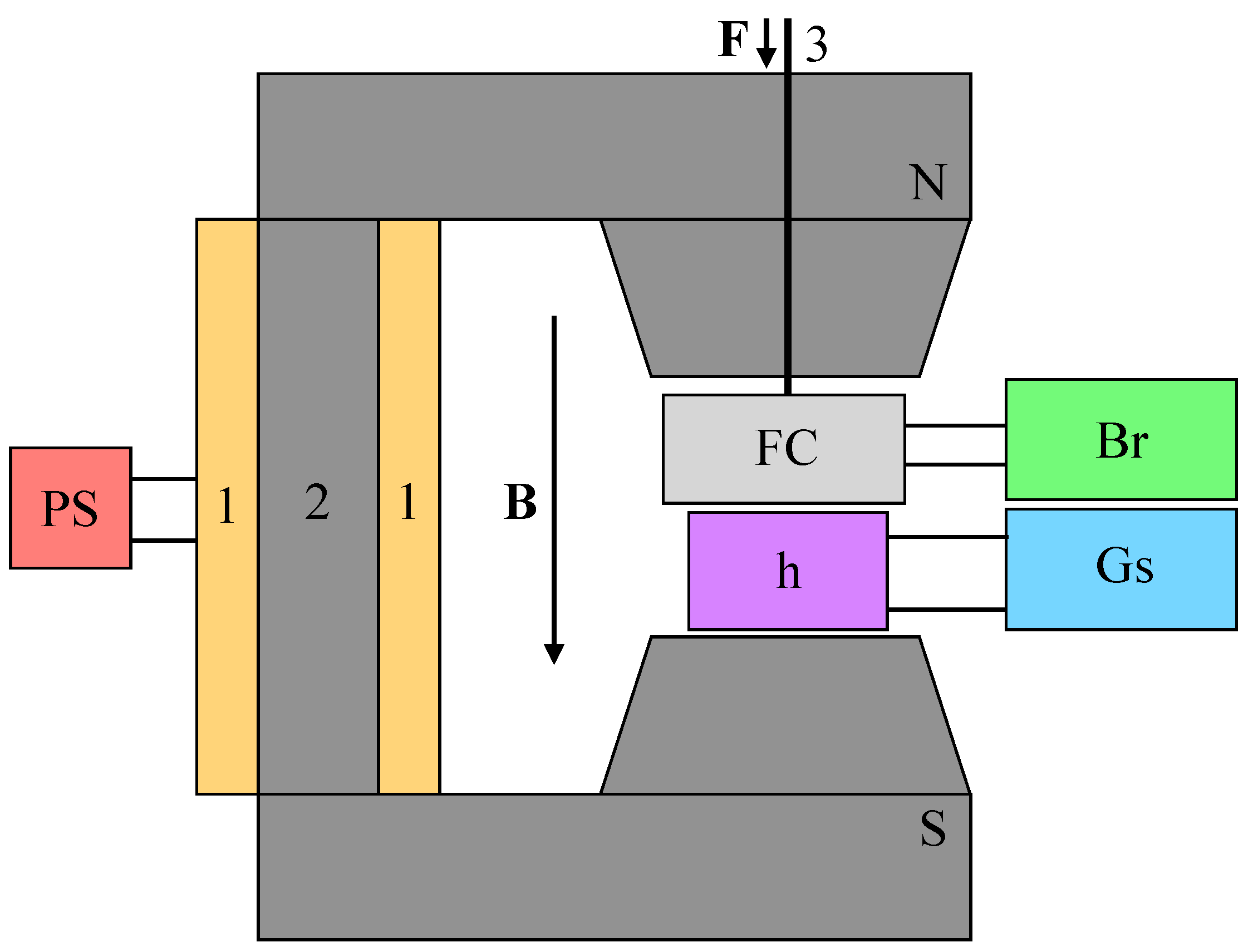
Figure 6.
The capacitance as a function of B, for fixed values of F. (a) . (b) .
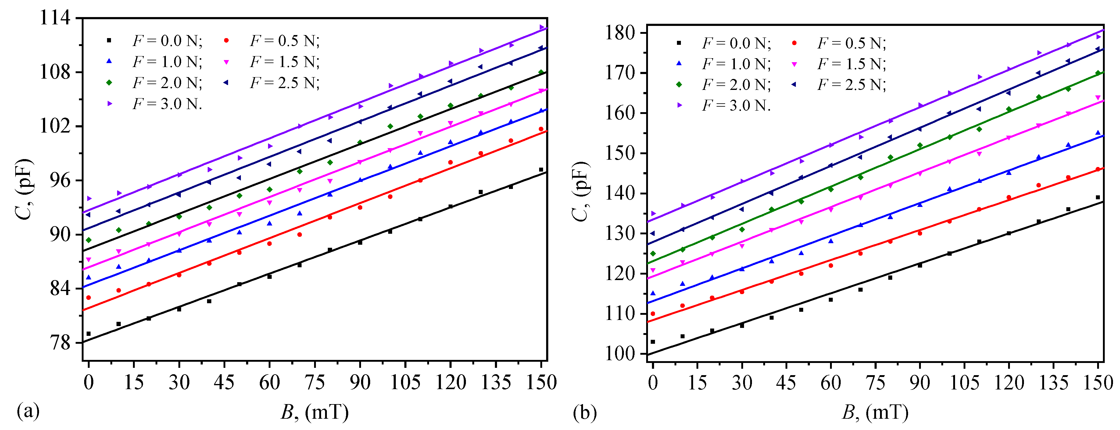
Figure 7.
R as a function of B, for fixed values of F. (a) . (b) .
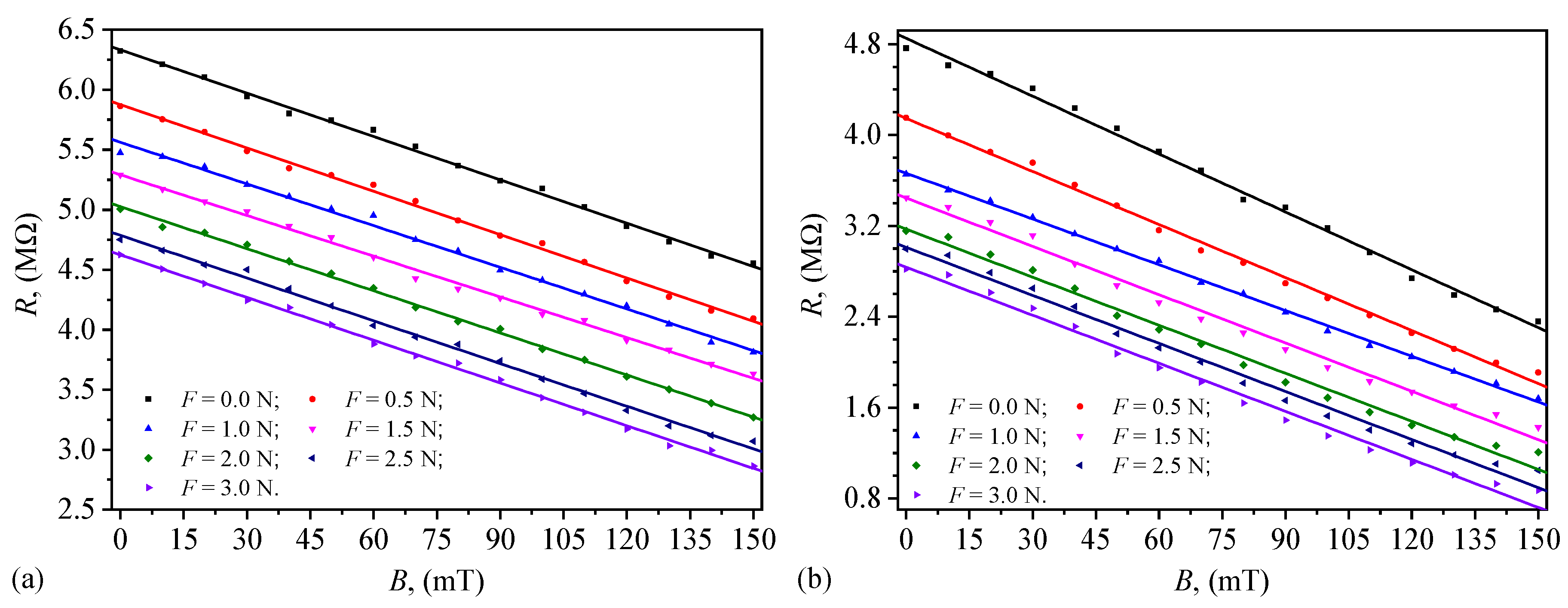
Figure 8.
as a function of B, for fixed values of F. (a) . (b) .
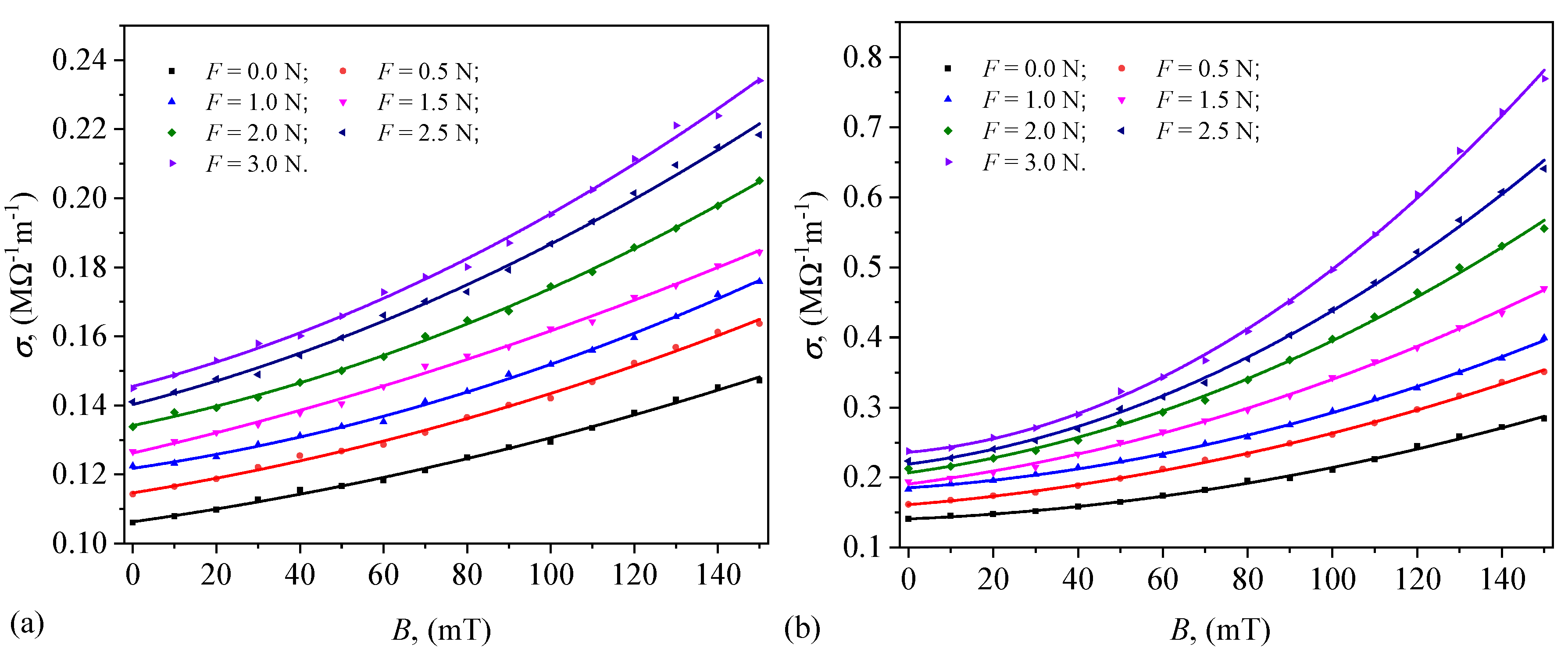
Figure 9.
Variation of (Equation 5) with B, for fixed values of F. (a) and (d) Quantification of C for , and respectively . (b) and (e) Quantification of R for , and respectively . (c) and (f) Quantification of for , and respectively .
Figure 9.
Variation of (Equation 5) with B, for fixed values of F. (a) and (d) Quantification of C for , and respectively . (b) and (e) Quantification of R for , and respectively . (c) and (f) Quantification of for , and respectively .
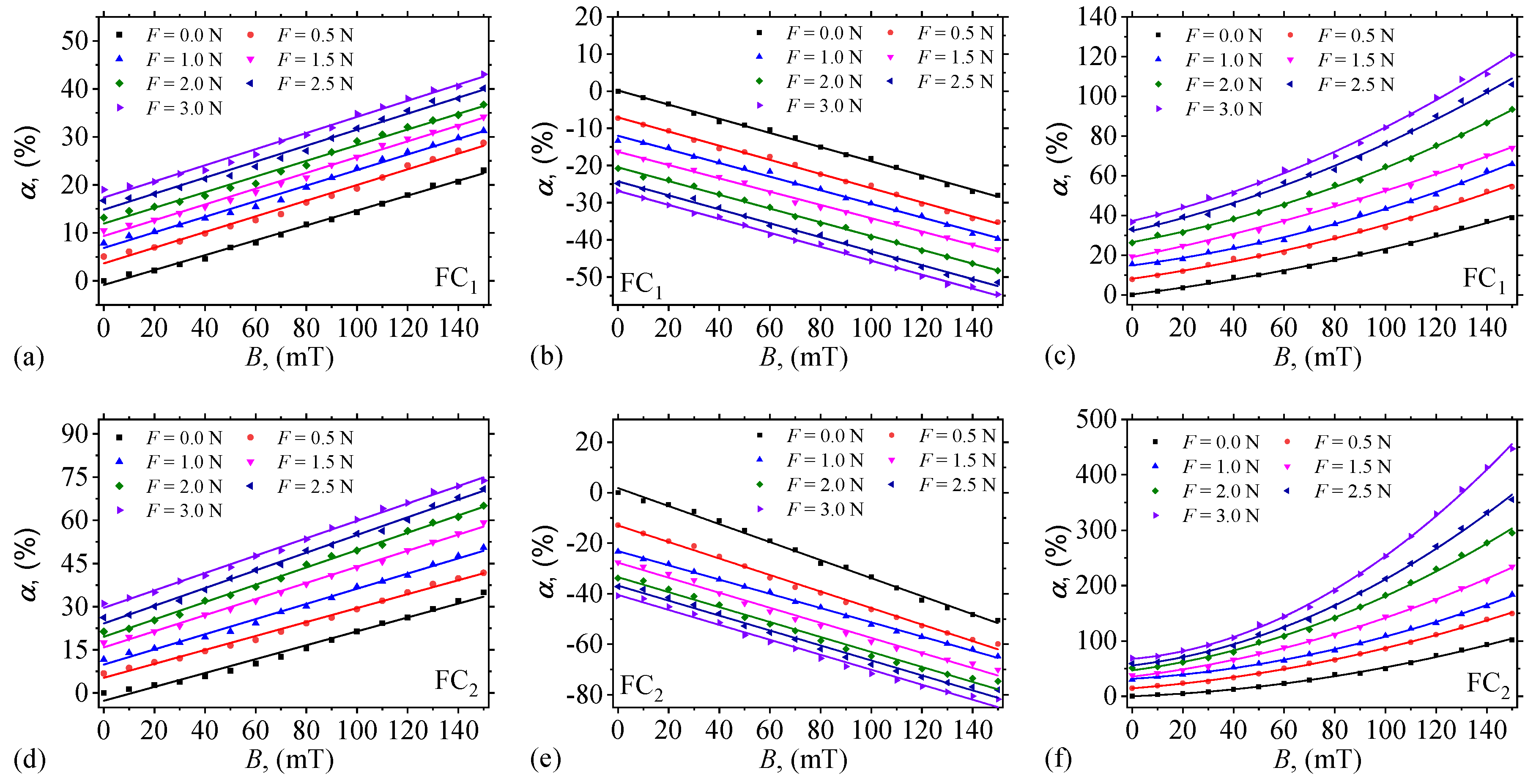

Table 1.
C, dielectric loss coefficient (D), relative dielectric permittivity (), dielectric loss factor () and mass density of MMPs, lard and cotton fabric.
Table 1.
C, dielectric loss coefficient (D), relative dielectric permittivity (), dielectric loss factor () and mass density of MMPs, lard and cotton fabric.
| Component | C | D | () | ||
|---|---|---|---|---|---|
| MMPs | 45.50 | 0.1007 | 16.4255 | 1.6540 | 3.388 |
| Lard | 17.65 | 0.0209 | 6.3717 | 0.1332 | 0.885 |
| Cotton fabric | 19.22 | 0.1783 | 1.4473 | 0.2581 | - |
Table 2.
Volumes, volume fractions, masses and mass fractions of lard (L) and MMPs (P).
| VL () | VP () | (% vol.) | (% vol.) | mL (g) | mP (g) | (% vol.) | (% vol.) |
|---|---|---|---|---|---|---|---|
| 6 | 4 | 60 | 40 | 6.126 | 7.772 |
Table 3.
Volumes, volume fractions of lard, MMPs, and microfibers f used in preparation of and . - saturation magnetization.
Table 3.
Volumes, volume fractions of lard, MMPs, and microfibers f used in preparation of and . - saturation magnetization.
| VL () | VP () | Vf () | (% vol.) | (% vol.) | (% vol.) | ( | |
|---|---|---|---|---|---|---|---|
| 0.20 | 0.14 | 0.14 | 42 | 29 | 29 | 9.68 | |
| 0.31 | 0.28 | 0.14 | 42 | 39 | 19 | 13.12 |
Disclaimer/Publisher’s Note: The statements, opinions and data contained in all publications are solely those of the individual author(s) and contributor(s) and not of MDPI and/or the editor(s). MDPI and/or the editor(s) disclaim responsibility for any injury to people or property resulting from any ideas, methods, instructions or products referred to in the content. |
© 2025 by the authors. Licensee MDPI, Basel, Switzerland. This article is an open access article distributed under the terms and conditions of the Creative Commons Attribution (CC BY) license (http://creativecommons.org/licenses/by/4.0/).
Copyright: This open access article is published under a Creative Commons CC BY 4.0 license, which permit the free download, distribution, and reuse, provided that the author and preprint are cited in any reuse.


