
Submitted:
06 March 2025
Posted:
06 March 2025
You are already at the latest version
Abstract
This paper comprehensively reviews research on the buckling failure performance of curved shell structures. It covers various aspects, including industrial applications, the development of buckling theory and guidelines, common failure modes, and recent advancements in experimental and numerical analysis. The paper also discusses the role of imperfections in triggering buckling and outlines potential future research directions to enhance the design and safety of lightweight structures. The study identifies research directions and future tasks concerning curved shells by suggesting several areas (such as experimental, numerical, analytical, and control variables) that require further investigation and utilisation.
Keywords:
Finite element analysis
; High-pressure engineering
; Metals
; Safety
; Reliability
; Non-metals
; Shell buckling
; lightweight structure
1. Introduction
Cylindrical structures with hemispherical or conical end closures (i.e., curved shell structures vessels) are widely used in various industries. However, these components are vulnerable to buckling under excessive loads, especially at the connection points, resulting in disastrous failures. Engineers must meticulously assess their designs' structural stability to avoid such occurrences. Failures of curved shells can be divided into four main categories that clarify the reasons for these breakdowns. Each failure category has an accompanying cause and a method that describes its background. For example, the failure of the structure could have been caused by corrosion fatigue stemming from the choice of unsuitable materials [1]. Designers need to understand the various types of failure as thoroughly as they comprehend the different categories and kinds of stress and loading. In the end, all of these elements are interconnected. Table 1 outlines the different categories of vessel failures.
Structural failures can be categorised based on their types, which illustrates how they occur. When addressing various types of failures, the designer must identify the stress condition in different components. The designer must evaluate and understand stress values related to the modes of failure. However, simply setting acceptable stress limits is insufficient when it comes to concerns about elastic instability. It is also important to consider geometry, stiffness, and the properties of materials. Selecting the appropriate material is vital and is directly related to the particular application planned. Design specifications and manufacturing techniques are just as crucial as allowable stress when it comes to developing vessels with a purpose for cyclic operation. The designer needs to have a comprehensive understanding of the vessel's operational environment
The various types of failures of which the vessel may encounter are outlined below.
- Elastic deformation: Elastic instability or buckling under elastic conditions, the shape of the vessel, and its stiffness, along with the characteristics of the materials, serve as safeguards against buckling.
- Brittle fracture: Brittle fractures have been observed in low-carbon steel vessels at low or moderate temperatures. During hydro testing, minor flaws have led to such fractures occurring in the temperatures ranging from 40 °F to 50 °F.
- Excessive plastic deformation: The stress limits for primary and secondary, as specified in ASME Section VIII, Division 2 [3], are designed to avert excessive plastic deformation and progressive failure.
- Stress rupture: Creep deformation occurs due to fatigue or cyclic loading, which leads to progressive fracture. While creep is influenced by time, fatigue is governed by cycles.
- Plastic instability: Incremental collapse is characterised by the progressive accumulation of cyclic strain that leads to damage and instability in vessels as a result of plastic deformation.
- High strain: Low cycle fatigue is influenced by strain and mainly occurs in materials that possess lower strength with high ductility.
- Stress corrosion: Chlorides are known to promote stress corrosion cracking in stainless steels, while caustic conditions can result in stress corrosion cracking in carbon steels. Selecting appropriate materials is crucial in these situations.
- Corrosion fatigue: This occurs when corrosive forces and fatigue effects occur simultaneously. Corrosion can reduce the fatigue lifespan by forming pits on the surface and accelerating crack development. The selection of material and its fatigue properties are crucial elements to be considered.
1.1. Buckling Failures in the Curved Structures
1.1.1. Failure due to Flow Discharge, Design Error and Crack
Dogangun et al. [4] recorded an unexpected collapse of a 16-year-old corn silo, see Figure 1(a). This abrupt rupture resulted in the release of about 15 tonnes of corn. The primary reason for the failure of the corn silo was overloading near the corroded region [5]. Moreover, uneven flow patterns caused by ratholes, preferred flow pathways, or irregular loading distributions of bulk materials during filling or emptying operations can result in silos becoming dented, buckled, or potentially collapsing.
A frequent design mistake of not understanding the flow pattern during the discharge process is a concern, where the designer needs to recognize the necessary flow pattern according to the functional requirements. The silo design should guarantee that the discharge process follows the assumed flow pattern. Additionally, the design of silos must be considered to withstand the pressure generated during the planned discharge process, which can differ based on the flow pattern. In addition, the real flow pattern might fluctuate between mass flow and funnel flow, influenced by various factors such as moisture, particle size, and the temperature of the material being stored [1]. As a result, any incorrect evaluation in any of these areas could result in inadequate usage, potentially leading to failures with severe consequences [6].
For instance, when flow through pipes is guaranteed by either geometrical design or mechanical equipment, the discharge pressure can be overlooked—except in the case of inclined pipes [7]. In contrast, unsymmetrical pressure must be accounted for when mass or mixed flow happens, regardless of whether there is partial contact with the silo wall [7].
Zaccari and Cudemo [6] documented the incident involving a steel silo filled with thousands of tons of limestone utilised in a thermal power facility. The incident was characterised by significant deformation of the wall, which was built with a stepwise variation in thickness. The event is linked to an error in calculating the pressure distribution caused by the flow of eccentric solids, as the flow behaviour is greatly affected by the characteristics of the stored materials. On the other hand, the material properties should be determined by testing representative samples of the material, instead of using some tables to determine the material properties that could be risky at best [6,7].
A structural failure due to excessive compressive stress at the cylinder-cone junction led to the collapse of the newly built Regent Street water tower in New Brunswick, Canada, as illustrated in Figure 2(a) and (b) [8]. It was noted that a combination of material deficiencies, design errors, and construction issues led to the collapse.
In Poland, a silo featuring corrugated stiffening, which was designed following Eurocode standards, suffered significant buckling in several of its vertical columns, as shown in Figure 1(b). Extensive analysis was conducted, comparing Eurocode 3 guidelines with nonlinear finite element (FE) analyses [9,10,11,12]. The design load against buckling for the silo was found to be excessively conservative when compared to the finite element results. Iwicki et al. [13] noted that the buckling strength of the columns was 2-4 times smaller than the allowable recommendation by Eurocode 3. On the contrary, the finding also indicated that initial imperfections and material nonlinearity significantly reduced the buckling load of the silo, leading to an inaccurate estimation of its strength. Thin-walled cylindrical tanks are particularly prone to buckling under internal vacuum conditions [14]. Alternatively, during sterilisation, steam condensation can lead to a decrease in volume and vacuum condition [15]. This causes a corresponding decrease in internal pressure, which may lead to the buckling or collapse of the tank. If such a collapse happens, it is often catastrophic, destroying the vessel (see Figure 3).
Figure 1.
(a) The failed accident of a 16-year-old silo [16] and (b) the buckled vertical column of an empty silo located in Poland [17].
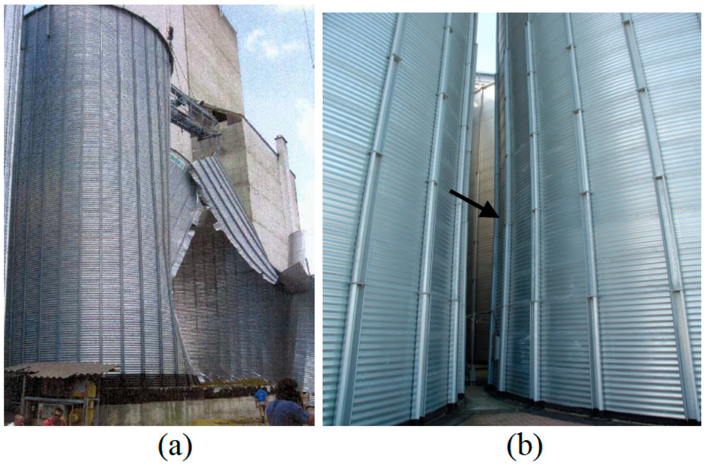
Figure 2.
(a) The water tower (such as an elevated conical tank) located at Fredericton, New Brunswick, Canada and (b) it collapsed [8].
Figure 2.
(a) The water tower (such as an elevated conical tank) located at Fredericton, New Brunswick, Canada and (b) it collapsed [8].
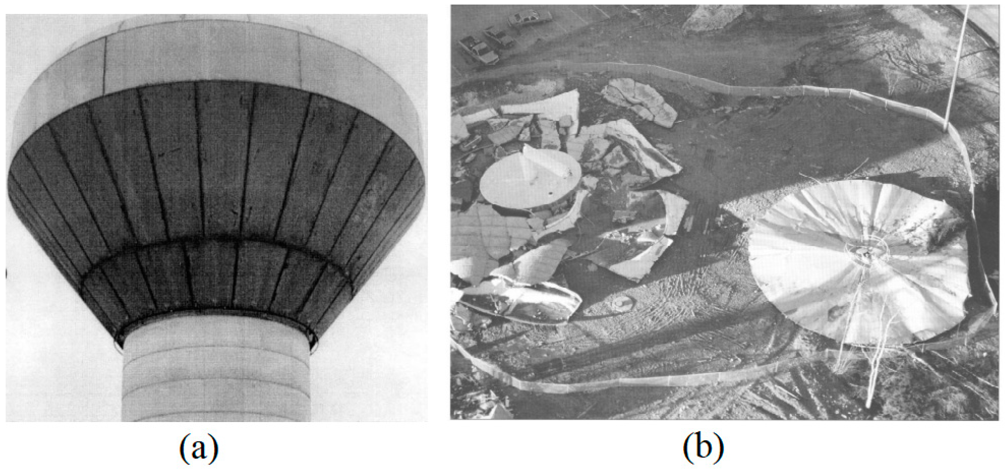
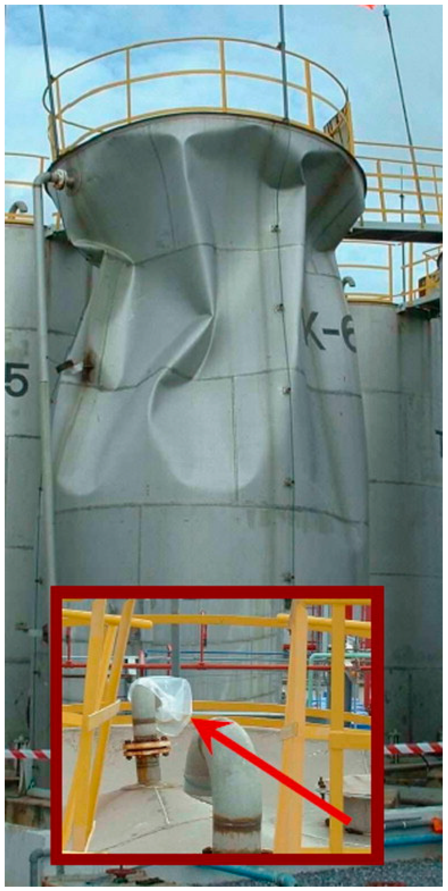
Figure 3.
An example of a pressure vessel collapsing due to a plastic sheet blocking a vent [15].
Figure 3.
An example of a pressure vessel collapsing due to a plastic sheet blocking a vent [15].
Cao et al. [18] examined the failure of a steel silo with a diameter of 10 meters and a height of 24 meters. They created finite element models of the steel silo that included a wide range of crack configurations: circumferential crack angles ranging from 10° to 60°, meridional crack lengths ranging from 0.5 to 3.0 m, and various crack heights. It has been widely known that both circumferential and meridional cracks have a notable impact on buckling deformations, primarily occurring around the location of the crack. The most critical location of the crack for structural buckling is identified in the lower part of the silo wall, and it is observed that the buckling load factor increases as the crack length shortens. Additionally, the existence of cracks proves to be more harmful to the buckling behaviour of silo structures with higher slenderness in comparison to those with lower slenderness [19,20].
1.1.2. Failure due to the Initial Geometric Imperfection and/or Manufacturing Defect
In 1988, Galletly [21] examined various instances of vessel failures in the industry, focusing on two types of load action: axial compression and external pressure. The review also provided a comprehensive discussion on the impact of initial geometric imperfections on shell failure. Several recommendations were made to prevent structural failure: the necessity of an experimentally validated design guideline covering a wide range of buckling problems, the vital use of lower-bound experimental design curves due to limited knowledge of initial geometric imperfections, the impracticality of using lower-bound curves for near-perfect manufactured shells, and the appropriateness of a random initial geometric imperfection for mass-production shells.
In 1955, Yoshimura [22] proposed a geometric explanation for the changes in the buckling mode shape. According to his findings, a typical cylinder can be converted into a polyhedral surface, forming consistent identical plane triangles without stretching the structure's mid-surface. The initial curvature of the triangles can be eliminated by minimising bending stress, while an increase in bending stress occurs along the ridgelines of the polyhedral. The failure pattern of a cylindrical shell can be linked to its thickness. A thicker shell may lead to an axisymmetric or asymmetric buckling pattern [23,24], whereas a thin shell tends to buckle in the form of a chessboard pattern [25,26,27]. The failure patterns exhibited by cylindrical shells based on the shell’s thickness are depicted in Figure 4(a) and (b).
In 1996, Hayes [30] conducted a comprehensive review of six pressure vessel failures, identifying the causes as the sudden collapse due to shock loading and the influence of residual stresses from insufficient heat treatment during stress relieving. Those cases underscored the importance of current design code recommendations for dealing with structural buckling. In practice, structural design is typically limited to simple isotropic shells in the form of a cylinder or cone. While analysing the structural response individually may be suitable from a design perspective, it may not be valid for global behaviours such as buckling, which requires consideration of the complex shell. Thin-walled structures are generally susceptible to imperfections and uncertainties, which significantly impact their load-carrying capacity [31]. Ismail et al. [32] conducted a failure analysis under pressure on a dome end cap using different industrial design codes.
Iwicki et al. [11] studied the buckling of cylindrical steel silos, which was triggered by the wall friction force resulting from the shearing action between the contents of the silo and its walls. Dynamic finite element analysis considering both geometric and material non-linearity was performed during eccentric discharge. Silo shells experienced axisymmetric and non-axisymmetric loads imposed by a bulk solid, following Eurocode 1. In geometrically non-linear analyses, the peak dynamic strength exceeded that of static analyses by 10-40% at significant wall imperfection amplitudes (w > 20 mm), while it was lower by 5-36% at minor wall imperfection amplitudes (w < 20 mm). In cases of analyses that are both geometrically and materially non-linear, the maximum dynamic strength was only slightly higher by 2-5% compared to static analyses. For load durations over 20 seconds, the inertial forces have negligible impact. Between 1 and 20 seconds, the dynamic buckling strength increases as the duration decreases, especially in non-linear analyses. This increase ranges from 10%-30% and 2%-15% for both imperfections. Subsequently, the material non-linearity significantly decreased the behaviour by 60%.
1.1.3. Failure due to the Thermal Load and Ratcheting
A silo collapsed in 1996 in the southwestern region of the United States. The incident took place at night, and the silo was neither in the process of being filled nor emptied during the collapse. A forensic examination demonstrated that the silo was insufficiently designed and failed to account for a phenomenon known as thermal ratcheting. The walls of metal silos expanded during the daytime and contract at night when temperatures decrease. In the absence of discharge and with the internal material being free-flowing, it settles as the silo expands. However, when the walls of the silo were contracting, the material cannot be forced back upward, resulting in resistance to contraction that caused increased tensile stresses in the wall. This effect was repeated daily, ultimately leading to the wall's failure. [1].
Matiaskova et al. [33] highlighted the importance of thermal loading in silos at high temperatures and how it affects the design of essential structural reinforcement. In silos, significant temperature gradients can develop when the stored clinker or cement is introduced into the structure while still hot. This issue can be addressed by incorporating reinforcement in the layer closest to the cooler surface to withstand thermal bending moments. Thermal loading (ΔTG) in silos should be considered independently at the highest filling level, not combined with discharge loads unless specifically required. Reinforcement for temperature loads near the silo top may exceed that for structural loads. Inadequate assessment can lead to severe and permanent cracking [34]. Temperature variations are the primary reason for the development of vertical cracks in the walls of silos. When adequate reinforcement is applied and the peak stress in the reinforcement remains below the yield strength, the cracks will reduce in width once the temperature variations stabilise [33,34].
Tauseef et al. [35] examined twenty-eight incidents involving significant fires and/or explosions that took place globally in tank farms containing flammable liquids. The research indicated that various codes and models predict significantly different distances for the placement of identical fuel storage tanks. Additionally, even if the distance between tanks adheres to a specific code/standard/model, an incident in one tank could still spread to another tank quickly enough to hinder the effectiveness of protective measures.
1.2. An Overview of Curved Shell Structures and Their Application
The issue of buckling in shell structures has consistently drawn the attention of numerous engineers seeking viable solutions, from the theoretical basis to experimental perspectives [36,37]. Certainly, several factors must be considered, such as load types, shell shape, initial imperfections, material properties, and boundary conditions. During service, these structures are exposed to various loads, primarily compression, external pressure, or a combination [38,39]. Lately, it has become increasingly clear that utilising significantly lighter and more slender cylindrical structural elements is advantageous, as their reduced weight plays a vital role in meeting buoyancy needs and affecting the total dead weight, which includes the payload. Therefore, it is necessary to conduct a detailed analysis of the buckling of slender structures [40]. Hence, a more rational design incorporating weight savings and economical fabrication of particular structures is required.
Figure 5.
Usage of composite materials in aerospace structures: (a) Boeing 787 and (b) Airbus A380 [41].
Figure 5.
Usage of composite materials in aerospace structures: (a) Boeing 787 and (b) Airbus A380 [41].
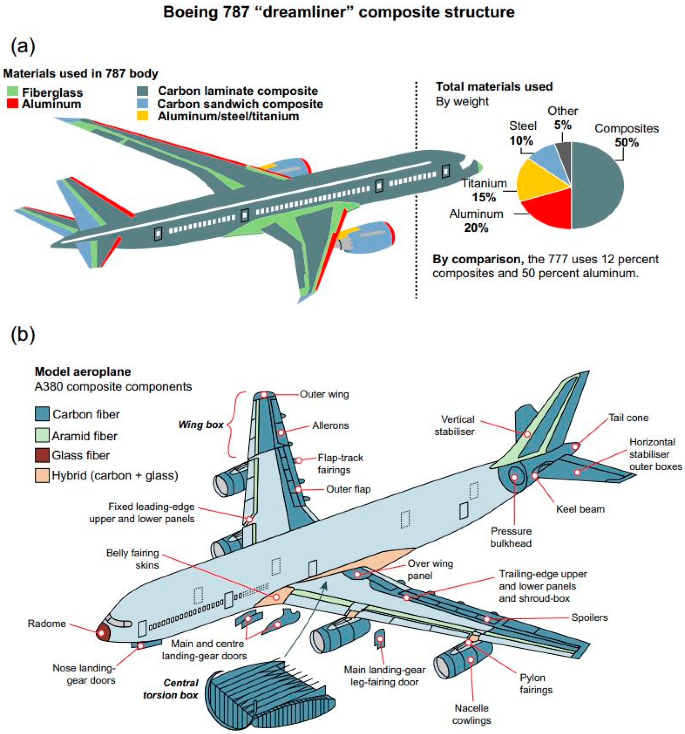
The European aircraft industry is expected to increase the use of composite materials to reduce development and operating costs by 20-50% in the future, as indicated by Degenhardt et al. [42]. The current design of Dreamliner 787 and Airbus aircraft series incorporates a significant amount of composite materials, particularly carbon fibre-reinforced plastic (CFRP), making up at least 50% of the entire structure A350. The utilisation of CFRP composites for airframe structures has surged from 15% in 1990 (A320) to over 50% in 2010 (A380), according to Ref. [43]. This trend highlights the potential of fibre-reinforced polymer (FRP) matrix composites to substitute high-strength isotropic materials. The current application of composite materials is primarily influenced by the aerospace industry, with a significant proportion of contemporary aircraft structures, like the Boeing 787 or Airbus A380 (refer to Figure 5), being constructed from carbon, glass, and aramid fibres. The principal material used for the matrix is a polymer, which exhibits low strength and rigidity. The key purposes of the matrix are to maintain the correct orientation and spacing of the fibres and to safeguard the fibres from wear and environmental factors [41].
The COCOMAT (Improved MATerial Exploitation at Safe Design of COmposite Airframe Structures by Accurate Simulation of COllapse) project, which was running from 2004 to 2008, focused on achieving a reduction in structural weight by tapping into significant reserves within primary fibre composite fuselage structures through precise and dependable simulations of post-buckling and failure [42]. COCOMAT is primarily focused on making significant progress from the present design scenario to a future one for standard stringer-stiffened composite panels. Figure 6 depicts the goals aimed for through a simplified load-shortening curve that includes buckling, post-buckling behaviour, and failure. The graph on the left represents the current industrial design situation. Three distinct regions can be identified. Region I comprises permitted loads under normal flight conditions and is defined by the limit load (LL); Region II is the safety zone and stretches up to the ultimate load (UL); Region III includes the prohibited area that extends up to collapse.
In aircraft design, the ultimate load (UL) must be 1.5 times the limit load (LL) if the structural analysis is conducted based on the limit loads, following FAA – Federal Aviation Administration Part 25 Section 25.303. Currently, the available design tools do not support the simulation of ultimate load scenarios, necessitating the use of this conservative safety factor of 1.5 by structural analysts.
A significant amount of structural reserve capacity exists between the present UL and the point of collapse, as illustrated in Figure 6(a). The intended design scenario for the future is depicted in Figure 6(b), where the UL is aimed to be positioned as close to collapse as possible. This shift can be achieved when structural analysis can be validated under the ultimate load conditions. By designing structures at the ultimate load level directly, the safety factor of 1.5 becomes unnecessary. This adjustment allows for the initiation of degradation to occur not in the prohibited Region III but within the safety Region II, similar to metallic structures where plasticity is allowed in the safety region.
Many engineering industries commonly use shell combinations, such as a cylinder with conical end closure. These combinations are found in pressure vessels as transition elements between two cylinders of different diameters, offshore platform legs, and in nuclear and chemical industries as flue gas desulphurisation (FGD) vessel assembly, as shown in Figure 7(a). Figure 7(b) describes an axially compressed cone-cylinder intersection along with its geometry, where the geometry terms r, L, and t are defined as the shell’s radius, height, and thickness. The subscripts denote a cylinder or cone, and β represents the cone angle. The axial load is indicated as F.
When considering the load acting on the structure, it is clear that the combination of the shells' self-weight and the weight of the component located on top of the cone may act as an axial compression load. This combined acting load may lead to structural instability of the shell structure. According to Schmidt [44], when a buckle appears on a cone-cylinder intersection, it necessitates a different approach as it is not a stand-alone structural issue. Knodel [45] initially studied the buckling of a steel cylinder-cone-cylinder assembly under axial compression numerically. Schmidt et al. [46,47,48] performed analyses of cylinder-cone-cylinder intersection under axial compression using numerical and experimental methods.
Their findings led to the recommendation of a conservative design approach, which was subsequently incorporated into the European Convention for Constructional Steelwork (ECCS) guideline: Part C [49].
1.3. The Role of Imperfection in Design Against Buckling Failure
During the initial assessment phase, structures were typically evaluated based on the design requirements using the design codes. If a structure met the code, it was considered safe. However, it became evident that this approach often led to overly conservative results, particularly concerning structural buckling. This was due to differences between older design codes used during initial construction and current assessment codes [50]. Current codes are more stringent, especially regarding structural imperfections and buckling. Decisions based on the assessment results for existing structures can have far-reaching implications compared to building new structures. Additionally, the costs of repairing existing structures can be impacted by usage and may result in additional expenses. For instance, shutting down a silo or pressure vessel for repairs can cause delays, disruptions, and extra costs.
The understanding of shell buckling issues remains limited despite decades of research and work in this area. Many criteria for shell instability design have been developed. Still, they are mainly based on the simplified assumptions for general shell designs (like cylinders, cones, and spheres) under uniform load conditions (such as axial compression, external or internal pressures, torsion, bending, and thermal effects). However, in practical industrial settings, a combination of these load conditions and geometric non-linearity is unavoidable. The shell stability design criteria applied to various structures are used in different industries, including offshore platforms offshore platform [51,52], aerospace [53], ship structure [52], pressure vessel [54,55] and general design code application for steel structure [49,56,57,58,59].
Domed caps that are subjected to external pressure are frequently utilised across various engineering fields. Due to their ability to support significant loads, they serve as partitions or closed ends in pressure vessels, or as covers for access ports in pressure vessels of different shapes used in subsea operations, aerospace (nose-domed), and civilian contexts [60,61]. To sustain the structural integrity, the material properties, pre-buckling deformations, and eccentric/concentric loading conditions play a vital role in internal pressurised domed caps [62]. In vacuum conditions, the strength and stability of the domed caps depend strongly on the design and geometric imperfections [60,63,64]. The domed caps are classified as a complete, deep, and shallow shell structure [65]. Several contemporary design standards such as the European Convention for Constructional Steelwork (ECCS) [66], Det Norske Veritas (DnV) [67], British Standard (PD 5500) [55], and the American Bureau of Shipping (ABS) [68] are used to design the domes.
The geometrical imperfection strongly affects the load-carrying capacity of the shell due to the deviations in geometry, material behaviour and boundary conditions. The geometrical imperfection is defined in terms of its position, dent-amplitude, shape, and size. The location of the imperfection has a strong influence on the load-carrying capacity of the structures [69,70,71,72,73,74]. The load-carrying capacity of the shell structure is referred to as the knockdown factor (KDF) (i.e., Pimp/Pperf). The buckling of domes with various geometric configurations and initial geometric imperfections has been extensively studied under uniform external pressure. For example, the initial geometric imperfections in the forms of linear eigenmode mode [75,76,77,78], local inward dimple [79,80], increased-radius imperfection and local flattening [81,82], measured geometric imperfections (MGI) [76,77,83], localized reduced stiffness method (LRSM) [84,85], and variations of measured shell thickness [76,86]. The uncertainty analysis of dome caps with a variation of industrial design codes has been reported in [87,88]. Some of the formulae that are most widely used to estimate the buckling load of spherical caps are Zoelly's analytical linear buckling formula [89], NASA SP-8032 KDF [90], Energy Barrier Criterion (EBC) KDF [91], Wagner KDF [65] and a closed-form lower-bound of KDF by Ismail et al. [75].
1.3.1. ASME BPVC Section VIII Div. 2 Approach Against Imperfection
In 2023, the ASME design code [3] specified requirements for Design By Analysis (DBA) in Part 5, particularly in Section 5.4: Protection Against Collapse From Buckling. Two methods are proposed to ensure structural integrity against buckling:
- Method A: involves a five-step procedure for elastic analysis. Each load case is assessed to confirm that the elastic analysis fulfils the necessary validity criteria. Subsequently, distinct allowable membrane stress is determined for each load case by utilizing an eigenvalue buckling analysis alongside the relevant capacity reduction factor, βcr, as specified in Section 5.4.2.2. If any of the validity requirements detailed in the procedure are not satisfied, then Method B must be employed. Fabrication tolerances must comply with the specifications outlined in Section 4.4.4. If the elastic analysis fails to meet the validity criteria, Method B must be used.
- Method B: This analysis involves elastic-plastic buckling and considers geometric imperfections as described in 5.4.3.1.
1.3.2. Imperfection Magnitude According to ECCS
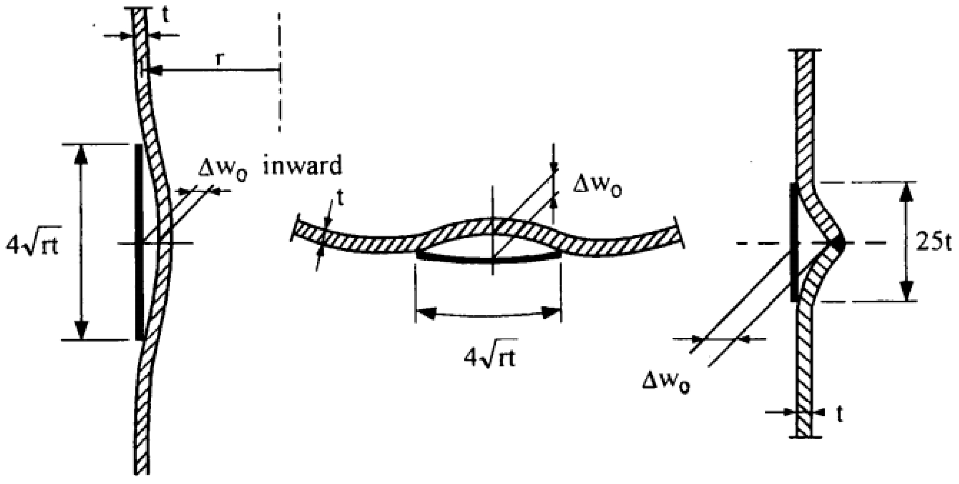
Table 2 provides examples of shell geometrical tolerance (imperfection) from selected design codes. Conversely, Table 3 offers examples of stiffened shell geometrical tolerance (imperfection) from selected design codes. The stringer-based tolerance/limitation from ECCS [92] appears to be adequate for addressing the bending stiffness of shells with a small number of stiffeners. However, for shells with numerous stiffeners, the bending stiffness seems to be minimal, making the unstiffened shell tolerance more applicable in this scenario. On the other hand, it is crucial to prevent local instability of stringer and ring-stiffened shells, ensuring that the cross-section ratios sufficiently comply with the design code requirements. Figure 8 provides explicit details of the expressions given in Table 2 and Table 3, as documented in [93].

Table 2.
Shell geometrical tolerance from selected design codes.
| Codes | Imperfection tolerance |
| DnV [94] | |
| ECCS [49] | |
| API [51] | |
| Eurocode 3 and Eurocode 9 [58,59] |
Figure 8.
Tolerance measurement for imperfections [95].
Figure 8.
Tolerance measurement for imperfections [95].
2. A Brief of the Development of Curved Shell Buckling Theory
Thin-walled cylindrical structures are widely used in various industries, including aerospace. These structures are often subjected to various loads during their service life. While significant advancements have been made in the design of these structures, ensuring their stability remains a critical challenge. Traditional linear bifurcation analysis, while useful, often falls short in accurately predicting the buckling behaviour of these structures.
In investigating the buckling issues, Refs. [96,97,98,99], are among the first group of researchers that conducted experimental studies on the shell structure for isotropic material. Throughout their work, it is claimed that the critical load calculation is about 3-8 times larger than the experimental failure loads. Tremendous effort was taken to explain the discrepancy between the experiment and the analysis regarding the buckling load prediction. Due to the large discrepancy in predicting the shell buckling load, the initial simplifying assumptions were then reassessed and proposed as a new design guideline. However, it can be seen that the interaction between extremely sensitive unavoidable imperfections as concluded by Simitses [100] and the post-buckling behaviour of the unstable shell structures were the main reasons for the large discrepancy, as suggested by Schmidt [47].
Another prospect for the development of shell buckling theories can be regarded as the establishment of “shallow shell theory” by Donnell [99]. This theory somehow becomes one of the first linear shells buckling theories at that time. Through his work, the critical load problem is reduced to one linearized eighth-order partial differential equation for shell deflection, solving numerous shell problems analytically before the beginning of the Finite Element (FE) era. The first theoretical shell buckling equation that solves the problem of the cylindrical shell under axial compression is expressed in Eq. (1).
The expression in Eq. (1) is explained as E, elastic modulus, t, shell thickness, and v, Poisson’s ratio. Before the limitation, the study on the understanding of large discrepancy has been the main research focus in the past few decades. This can be accounted for in the works by Flungge [97] and Stein et al. [101,102] on investigating the effect of pre-buckling deformations. Meanwhile, others like Ohira [103] and Hoff et al. [104,105] take into consideration the effect of in-plane boundary conditions and geometrical imperfections. The sensitivity of imperfection was established through strict post-buckling analysis from the perfect structure configuration [106,107,108,109].
2.1. Design of Curved Shell Structures and the Associated Considerations
Most aerospace and aircraft structures are designed as of thin-walled structures, which lead to issues with buckling, instability, and collapse due to their susceptibility to buckling [110]. Specifically, the buckling load of a thin-walled cylinder structure under axial compression is a classic structural problem. In practical applications, lightweight structures in commercial aircraft or launch vehicle fuel tanks experience flight loads and internal/external pressure during operation [111]. Under certain conditions, some of these loads may act primarily as compressive loads due to the structural weight and payload during operational use. Therefore, it is essential to investigate to characterize the structural buckling event to ensure safety and reliability.
The prediction of buckling load in typical cylindrical shell structures often shows significant discrepancies between experimental and theoretical results, mainly due to the presence of imperfections in real structures. These imperfections can be categorised into three types: geometrical, material, and load-boundary conditions before buckling [36]. Geometrical imperfections are related to the shape, dimensions, and overall geometry of the structures. Material imperfections stem from differences in properties such as elastic modulus, yielding properties, and strain rate, particularly in isotropic materials. Composite materials, in particular, introduce complexity and nonlinearity due to the factors like fibre-angle misalignment, local ply-gaps, and stacking sequence, all of which significantly impact structural imperfections [112,113].
The impact of the load-boundary condition remains significant in causing imperfections. This is evident in the buckling event, where it is challenging to define the actual buckling boundary condition precisely. It is important to highlight that during the compression event; the compressive load may not always act perpendicular to the cylinder [114]. Additionally, this event results in an uneven distribution of load along the cylinder's circumference, potentially causing bending effects throughout the buckling process.
2.2. Current Design Guideline
When it comes to aerospace structures, the estimation of the knockdown factor, denoted as ρ, still heavily relies on the empirical guidance provided by NASA SP-8007 [115], which utilizes the conservative lower bound curve (see Figure 9). Despite its effectiveness, the European counterparts typically favour the European Convention for Construction Steelwork, ECCS [116], when designing thin-walled structures. It is worth noting that the subsequent ECCS guideline is largely based on NASA SP-8007 itself. Regrettably, the guideline is primarily tailored for isotropic materials and provides limited information regarding composite materials. Additionally, the imperfections in cylindrical structures are not clearly defined, leading to an underestimation of the knockdown factor and buckling load. It is important to highlight that the derived knockdown factor represents a normalized value obtained by comparing the experimental buckling load with the linear bifurcation load (ρ = Pexperiment/Plinear).
Figure 10 shows the schematic diagram of a spherical shell subjected to external pressure. The terms are denoted as external pressure, P, spherical radius, R, spherical thickness, t, base radius, r, spherical height, H and semi-vertex angle, φ. This analytical method for calculating the buckling load of a steel spherical shell subjected to external pressure using design codes (i.e., ECCS and PD 5500) is shown in the following section [118,119].
Normally, the design codes use conventional working stress to determine each mode of failure. Apart from the working stress, the design code also considers several uncertainties such as safety factors, eccentric boundary condition and load, material hardening and structural imperfection of the tested spherical shell structures. The critical buckling formula, Pcr of a complete spherical shell under external pressure was proposed by Zoelly [121] as shown in Eq. (2).
where the terms are defined as the shell radius, R, shell thickness, t and material Poisson’s ratio, ν.
2.2.1. NASA Design Guidelines
The prediction of the knockdown factor relies heavily on the empirical guidelines from NASA SP-8007 [115], which utilises a conservative lower-bound curve. While successful, European counterparts often prefer using the European Convention for Construction Steelwork, ECCS [116], for designing thin-walled structures. Interestingly, the subsequent ECCS guideline is generally derived from NASA SP-8007. Unfortunately, the NASA SP-8007 guideline is primarily intended for isotropic materials, providing less information for composite materials. It is important to note that the derived knockdown factor (KDF) is a normalized value between experimental buckling load and linear bifurcation ones (Pexperiment/Plinear). The KDF of a cylindrical shell for NASA SP-8007 is defined as Eq. (3).
The term can be calculated using Eq. (4).
The empirical formula based on the NASA SP-8032 [122] is comprehensive and adaptable when addressing various shell buckling challenges that are specific to spherical shells. The calculations according to the NASA SP-8032 guideline are conducted under specific conditions; as stated in NASA SP-8032, the shell parameters, λ, are determined using Eq. (5).
The dome cap knockdown factor (KDF) is calculated by Eq. (6) as
2.2.2. ECCS Design Rule
The ECCS design rule estimated the collapse pressure as referred to Eqs. (7) and (8).
The factor of Ce is the function of boundary that can be referred in [66]. The factor of Ce covers the buckling resistance reduction caused by different boundary conditions of the elastic spherical shell. The elastic modulus is defined as E. The plastic reference resistance is derived in Eq. (8). The factor of Cpl is the factor that covers the buckling resistance reduction caused by different boundary conditions of an elastic-plastic spherical shell.
The spherical shell slenderness parameter λ is defined by Eq. (9).
The buckling reduction factors, χ should be determined as a function of the relative slenderness of the spherical shell (i.e., λ, λ0 and λp) that can be expressed in Eq. (10).
The term α is the elastic imperfection reduction factor (‘knock-down factor’), β is the plastic range factor, η is the interaction exponent which describes the shape of the elastic-plastic buckling interaction between λ0 and λp. The term λ0 is the squash limit slenderness. The term, λp is the plastic limit slenderness (i.e. the value of λ below which plasticity affects the stability) given by Eq. (11).
The buckling pressure estimated by ECCS is expressed by Eq. (12) as the χ is referred to as the stability reduction factor.
The ECCS design code [92,116], was the pioneering standard to address both the strength and stability of shells and the initial attempt to encompass all types of static structural analysis within the same design principles. It offers a comprehensive commentary on existing regulations regarding buckling and is the first set of guidelines to consider numerical solutions. Additionally, it incorporates hand calculation assessments. Moreover, the code goes beyond its basic function by providing recommendations, expansions, advice, warnings, explanations, and examples.
Regarding Eurocode terminology, typical numerical analyses have been designated as (i) LBA – an analysis for linear buckling (eigenvalue), (ii) GMNA – an analysis for geometrically and materially non-linear perfect shell, and (iii) GMNIA – an analysis for geometrically and materially non-linear imperfections. Figure 11 illustrates the stability capacity curves for a cylindrical shell structure, depicting the relationship between the buckling strength, χ, and the relative slenderness ratio, λ. The buckling strength, χ, is defined as the characteristic resistance Rk, obtained through experimentation or from a geometrically and materially nonlinear analysis of the imperfect structure (referred to as GMNIA, resulting in RGMNIA = Rk). The relative slenderness is defined by the plastic limit reference resistance Rpl (small displacement theory with ideal elastic-plastic analysis (MNA), resulting in RMNA = Rpl) and the linear elastic critical resistance Rcr (linear bifurcation analysis (LBA), resulting in RLBA = Rcr).
2.2.3. PD 5500 Design Rule
The PD 5500 design code estimated the collapse pressure by referring to Eqs. (13)–(14).
The design pressure for the case of the spherical shell under elastic-plastic conditions subjected to uniform external pressure is defined by Pyield. The Pcr and Pyield shall be determined in referring to Eqs. (1) and (11), respectively. Usually, acceptable design pressure is controlled by the safety factor fitted to the test data. For the case of an externally pressurised spherical shell, the mean strength curve (PPD 5500), PD 5500, adopts a safety factor of 1.75.
2.3. Some Commentary on Current Design Guidelines and Their Limitations
Zhao and Bai [124] conducted a comparative study of externally pressurised spherical shells using design codes. A total of 80 samples are evaluated consisting of (i) complete spherical shells and (ii) spherical caps. Three (3) different aspects of spherical shell parameters including (a) shell shape, (b) radius-to-thickness ratio R/t and (c) geometrical parameters to evaluate their performance. The conclusion of the comparative study of tested design guidelines is listed in Table 4.
Figure 12 and Figure 13 illustrate a thorough evaluation of 28 spherical shells that were tested under external pressure and were chosen for comparative analysis against the lower bound curves outlined in PD 5500 [55] and ECCS [66]. This test revealed a minimal difference from the design curve established by the guidelines. The findings demonstrate the ratio of the critical buckling pressure of the spherical shell within the elastic range compared to the buckling pressure of the spherical shell in the elastic-plastic range. Additionally, Figure 13 displays more conservative experimental outcomes for three tested spherical shells, as it is positioned below the ECCS curve [131] when compared to the PD 5500 curve. The results indicate that the PD 5500 design rule is more conservative compared to the ECCS design code.
Ismail et al. [32] evaluated a real case study of failed vessels. Their study focuses on pressurisation damage to an oil storage tank’s spherical shell partition, which was investigated previously by Jones [132]. Using NASA SP-8032 [90] as a reference, Figure 14 illustrates the comparison of design pressure determined using various modern design guidelines with the minimum internal pressure within the vessel, which serves as a threshold. In the normal functioning of the tank, the spherical shell partition is anticipated to endure the hydrostatic pressure of 0.032 MPa created by crude oil. Following the condition, the design pressure predicted by NASA SP-8032 [90], Ismail et al. [75], Wagner [65], ECCS Class C [66] and ABS [68] guidelines somehow under design the spherical shell partition. This implies that the spherical shell partition fails, according to the stated design guidelines. PD 5500 [55] and ECCS Class A and B [66] guidelines, the spherical shell partition remains intact with a built-up pressure of 0.132 MPa. Nonetheless, it is also suggested that the design load also include a value of safety factor (e.g. 4/3 in compliance with ECCS [66]). The calculated bifurcation pressure (Pbif = 0.120 MPa) from the numerical findings was verified to be significantly below the tank's threshold pressure.
Figure 15 compares the knockdown factor derived from (i) NASA SP-8032 [90], which is based on a total of 343 experimental samples. The results indicate that the knockdown factor forecasted by NASA SP-8032 does not align with various experimental findings. This indicates that NASA SP-8032 is not suitable to be considered a lower limit for the knockdown factor. While the outcome supports the conservative approach of NASA SP-8032 [90], numerous data points remain below the curved threshold.
3. Curved Shell Buckling
Curved shell structures with thin walls are commonly utilised in various industrial applications. Nevertheless, thin cylindrical shells are susceptible to buckling failures resulting from applied compressive loads. Structures with excessively thin cylindrical shells and higher design loads may increase the likelihood of buckling failure.
3.1. Experimental Works on Curved Shell Buckling
Almroth et al. [134] have provided updated insights on the experimental research on shell buckling for the unstiffened cylinders, while Weller et al. [13] have done the same for integrally stiffened cylinder shells. The test specimen is expected to meet high standards in terms of the material quality and fabrication. Additionally, for the laboratory use, the cylinder specimen should have a small radius-to-thickness ratio to avoid the complications associated with larger specimens. This is to prevent the need for conducting extensive and expensive experimental programs, and instead consider a more efficient solution known as a sub-modelling cylinder [135,136]. Conversely, the geometrical aspects of the cylinder shell must be manufactured with precision, as even a slight variation in shape or measurement could significantly impact the buckling load. Nameth & Starnes [137] have also concurred with these issues and proposed the introduction of accurate analytical nominal shells model knockdown factors. These recommendations are typically made before future experimental programs and the design of NASA shells.
Degenhardt et al. [138] examined the impact of variations in matrix volume on the material eccentricity of typical composite materials. They found that a larger gap in fibre volume could lead to an increase in the material stiffness. Consequently, this new stiffness component could affect the plies and result in thickness imperfections. Furthermore, various studies have investigated the influence of laminate orientation on the buckling strength of composite cylinders [114,139,140,141]. It is important to consider the loading and boundary conditions before conducting experimental techniques. Similar to fabricated models, it is crucial to ensure that the appropriate boundary conditions are met, as they strongly influence shell buckling load predictions. In the past, simply supported buckling conditions were commonly used for easy comparison with the theoretical ones.
Researchers such as Geier et al. [142], Han et al. [143], and Kirkpatrick & Holmes [144] utilised the simply-supported boundary condition in cylinder compression tests. However, this boundary condition is now considered unsuitable for compression tests due to the superior solution provided by the FE numerical method for all boundary conditions. Achieving simply supported boundary conditions in real tests is also considered very challenging. Therefore, it is important to note that a fully-clamped condition is considered the best option, as suggested by Arbocz & Hol [145]. Complete clamping can be achieved by applying epoxy-based material at the cylinder edge or by using a mandrel around the cylinder circumference, as demonstrated by Starnes & Hilburger [146,147].
During the 1970s, the Technion Aircraft Structures Laboratory and NASA [148] carried out extensive experimental studies on buckling, focusing solely on closed stiffened cylindrical shells. The buckling analyses of these shells were based on linear theory and showed good agreement with the experimental data. However, the research was limited to the configurations of closed-spaced stringers as detailed by Krasovsky et al. [26]. The theoretical and experimental results for cylindrical shells with moderate or sparse stiffening were deemed unsatisfactory. When assessing the performance of stiffened cylindrical structures, certain considerations must be carefully considered. For instance, the imperfection sensitivity of stiffened stringer cylinder shells is less affected by structural mass/weight increase compared to the unstiffened panels [149]. It is important to note that the imperfection sensitivity of the stiffened cylindrical shell is influenced by the design of the stiffener profile and its position (inside/outside) around the cylinder's circumference [150,151,152,153]. Cylindrical shells with externally reinforced stiffeners are more imperfection-sensitive than internally stiffened panels [154].
In the early 1990s through the 2000s, research on stiffened cylinders was not particularly widely pursued. Krasovsky et al. [26] and Bisagni & Cordisco [155] conducted studies examining the performance of stiffened cylinder structures made of steel and CFRP materials, respectively. Nevertheless, there have been relatively few published works on this topic during those periods. Crucial information regarding effective guidelines or design rules for the creation of stiffened cylinders remains insufficient. Hence, an update is necessary to tackle new design challenges following contemporary technological requirements.
Buckling analyses of an axially compressed stiffened/unstiffened cylinder structure were evaluated with the use of a probabilistic approach [156,157]. Two distinct cases were presented and analysed. In both instances, the methodology relied on statistical analysis of imperfections observed in nominally identical specimens. Non-linear finite element analysis was employed for strength evaluation, and the outcomes of the statistical analysis were incorporated into the imperfection modelling. It was shown that this approach has benefits over traditional code designs relying on 'lower bound' curves, not only in the estimated buckling loads but also in providing a systematic and logical method for evaluating randomness in imperfections.
Stiffened cylinders with flat-bar ring frames subjected to external pressure were comprehensively discussed in [158]. From the analysis, relevant pre-test measurement findings were provided, along with a comprehensive explanation of the testing process. The experimental response of one model was analysed, focusing on the development of strains within the ring stiffeners and the shell. The corresponding deflection data was presented, and the failure mode was outlined. The maximum pressure threshold and failure characteristics of the second model, which exhibited welding residual stresses, were discussed and contrasted with those of the first model. Similar studies concerning weld imperfection were also conducted in [159,160,161,162].
Jones [132] documented real-life instances of buckling failures in the pressurized vessels. In a study by Teng & Zhou [163], advanced finite element analyses were utilised to investigate pressure vessels that had previously failed as reported by Jones [132]. Teng & Zhou [163] also assessed the accuracy of the formulas used to assess real vessels with geometric imperfections by comparing theoretical predictions with the experimental results, revealing the limited impact of initial imperfections on buckling load sensitivity. The analysis of axially compressed cylindrical shells highlighted the significance of initial geometric and loading imperfections. Subsequent research by Iwicki et al. [12] involved conducting failure analyses on cylindrical silo shells using both linear and non-linear buckling analyses with various initial geometric imperfections. To prevent unforeseen catastrophic failure of structures where thin cylindrical shells play a crucial role, designers and engineers must possess comprehensive knowledge of shell buckling behaviours.
Cone-cylinder shells are commonly utilised as pressure vessels in both ocean engineering and the chemical sector [164]. Typically, the failure patterns of pressurized cone-cylinder shells fall into three distinct categories: (i) axisymmetric failure, (ii) non-symmetric buckling, and (iii) buckling at the intersection of the cone and cylinder due to localized circumferential compression. These failure modes are identified by the formation of waves around the structure of the shell during or following a buckling event [165]. When subjected to internal pressure, localized stresses are found to peak at the connection point between the cone and cylinder, in contrast to other areas of the shell. The elevated local stresses primarily arise from the slope discontinuity and the vulnerability to plastic collapse, as indicated by Teng [166]. It is crucial to pay particular attention to the presence of significant hoop stress at the junction, which can lead to failure, manifesting either as axisymmetric collapse characterized by excessive inward deformation or as non-symmetric buckling.
In operation, the internally pressurized silo (cone-cylinder junction) is anticipated to endure over-pressure conditions due to the limited areas of the wall. A few studies are mentioned in [167,168,169,170]. However, the cases involving burst pressure that have been observed in practice are quite rare. For safety considerations, Rotter [171] recommended that the design of the entire wall should be such that it can withstand the maximum pressure envelope. It is important to highlight that most failure cases stem from inadequate silo design rather than extreme pressures. The overpressure condition is frequently linked to inward-bulging imperfections, according to Jenike et al. [168]. Several pressure vessel codes prohibit the use of cone-cylinder intersections without a toroidal knuckle when the cone half-apex angle is less than 30° under the internal pressures [55,172]. However, the American Society of Mechanical Engineers (ASME) code [54] permits the estimation of the buckling load that the shell might withstand. Additionally, reinforcement at the shell junction is necessary when the cone half-apex angle exceeds 40°.
3.2. Numerical Works on Curved Shell Buckling
The early development of FE codes known as STAGS (STructural Analysis of General Shells) played a significant role in studying the buckling behaviour of cylinder shells through numerical analysis. Brogan & Almroth [173] previously tested this code in their 2D Finite-Difference analysis of elastic collapse in shell structures. Riks et al. [174,175] measured the imperfections of the cylinder before developing the code, incorporating various loading conditions into their FE analysis. Their findings demonstrated the capability of numerical simulation to accurately depict the buckling mechanism process. This study was one of the first works to recognize the impact of structural mode-jumping. Over time, more FE codes have been developed, aiming to enhance accuracy by integrating high-fidelity nonlinear analysis.
The high-fidelity nonlinear analysis can accurately predict the buckling non-linear response of thin shell structures. Hilburger & Starnes [176] demonstrated this type of analysis by incorporating the real cylinder imperfection measurement into the nominal FE cylinder model through a user-written subroutine. The researchers in [177,178,179,180] conducted a comprehensive analysis of the impact of imperfection based on manufacturing signatures, which involved adjusting the shell wall thickness, lamina ply-gaps, cylinder mid-surface imperfection, and boundary conditions.
Tafreshi [181] concluded that cut-outs with different widths but the same area would decrease the buckling load. The response was significantly affected by the size of the cut-out and the level of internal pressure. Bisagni [182] and Meyer-Piening et al. [183] also studied the impact of cylinders under compression and torsion. They found that the cylinder is more sensitive to imperfections under single axial load compression compared to compression and torsion combined. Tafreshi & Bailey [184] also observed that the cylinder is sensitive to bending conditions, and certain load combinations may enhance the cylinder's ability to withstand the load. However, under specific load combinations such as compression and external pressure, the imperfections were found to have a greater impact on the cylinder's structural performance. Apart from that, the analyses of cylinders with cut-outs subjected to mechanical loads were reported in Refs. [181,185,186,187,188,189,190,191,192]. It was generally found that the structural strength and buckling load increased with higher internal pressure due to the outward lateral pressure directions countering the inward compression of the shell walls. The reports highlighted the significant role of internal pressure in strengthening the shell's structure.
Numerous studies have investigated the performance of cylinders subjected to axial load compression, considering both reinforced cut-outs and unreinforced structures. Combinations of quasi-static and transient dynamic analyses were employed using STAGS codes [134,179,185,190]. The numerical evaluations were supplemented by analyses of progressive failure both within and between layers. The studies found that the shell experienced significant nonlinear buckling near the cut-out due to local deformation and stress concentration. Adding reinforcement to the cut-out area generally improved the buckling load, but in some cases, it could lead to increased local stress and interlaminar failure. The buckling and post-buckling behaviours of both perfect and imperfect cylindrical shells, which are orthotopically and stringer stiffened, have been analysed under axial compression and external pressure or a combination of both using boundary layer theory [193,194]. The research has recently been broadened, as noted by [111,195,196,197]. Other relevant studies also reported in [196,198,199,200,201].
Shell configurations, like cylinders with conical end pieces the common use of shell configurations, particularly cylindrical structures with the conical end pieces. This design choice is often driven by aesthetic considerations and cost-efficiency. The conical section serves as a transition between cylinders of different diameters. Such configurations find applications in various industries, including pressure vessels, offshore structures, and FGD vessel assemblies. The axial compression forces exerted by the self-weight of the shell and the weight of components placed on top can potentially lead to buckling failure. Therefore, careful consideration must be given to managing these loads to ensure structural integrity.
Numerical analysis was often utilised to complement the experimental work. Dinkler and Knoke [202] conducted a numerical investigation on the axially compressed imperfect cone-cylinder transition in subsequent years. It can be inferred that when considering (i) elastoplastic behaviour, there is a strong correlation between the numerical investigations and the European recommendations ECCS. Moreover, the German design rule Deutsches Institut für Normung (DIN) 18800 [203] offers notable additional advantages. Conversely, in the case of (ii) elastic material, the buckling behaviour of unstiffened combined shells, such as cylinder-cone configurations, is similar to the validated buckling cases of single shells.
Schmidt [44] indicated that once a buckle initiates at the intersection of a cone and cylinder, specialized treatment is necessary since it is not merely an isolated structural issue (like just a cone or a cylinder). Under different loading scenarios, the stress state in the multi-segment shell forming the revolution assembly mainly exhibits membrane stress away from the intersection; however, as one approaches the intersection from either direction, the stress state transitions from membrane stress to a blend of membrane and bending stresses [204,205,206,207,208]. Typically, failures in a cone-cylinder assembly occur primarily at the intersection. This behaviour is linked to the change in slope at the shell meridian at the junction, which leads to localized bending and circumferential stresses. Due to the local weakening at the intersection, reinforcements are commonly applied to enhance the shell's integrity at the junction, either by thickening the shell or by adding a ring at the intersection.
Zingoni [204] formulated an equation to assess the effects of discontinuity at the junction of a cone-cone assembly under various loading circumstances. The equation accounts for both membrane and bending effects in the shell structure. This is because the shell is expected to initially buckle in a membrane state, but the bending deformations will also play a role. The discontinuity effect, which arises at the junction of different shell sections, is incorporated by enforcing geometric continuity and equilibrium conditions at this point.
Schmidt [44,47] noted a notable distinction in the buckling mode observed in the case of axially compressed steel cylinder-cone-cylinder structures. The experiments revealed that the specimen (ZKZ-XV10) underwent local bending, which initiated unexpected behaviour in a small area of the junction and the cone section. The behaviour of load-carrying and failure modes in the cylinder-cone-cylinder transition was quite intricate under axial load tests. For instance, the shape of the buckling mode shifted from the small area junction during linear analysis (LA) to the large area junction through geometrical nonlinear analysis (GNA). Even though both analyses are at the bifurcation level [66], neither numerical analysis (bifurcation or nonlinear) accurately predicted the buckling mode pattern observed in the specimen. Additionally, in the scenario involving 1 mm thickness, the numerical results (GMNA) fell short in estimating the experimental buckling load.
Externally pressurised domed caps are commonly used in many engineering applications. Following their high load-carrying capacity, they are used as partitions or closed-end in pressure vessels, or as hatches to cover the access ports of variously shaped pressure vessels in subsea applications, aerospace (nose-domed), and civilian applications [60,61]. To sustain the structural integrity, the material properties, pre-buckling deformations, and eccentric/concentric loading conditions play a vital role in internal pressurised domed caps [62]. In vacuum conditions, the strength and stability of the domed caps depend strongly on their design and geometric imperfections [60,63,64]. The domed caps are classified as a complete, deep, and shallow shell structure [65]. Several contemporary design standards such as the European Convention for Constructional Steelwork (ECCS) [66], Det Norske Veritas (DnV) [67], British Standard (PD 5500) [55], and the American Bureau of Shipping (ABS) [68] are used to design the domes.
4. Research Direction and Future Works
The review work emphasises the importance of lightweight, slender structural components in meeting the flexibility requirements and reducing overall weight, particularly in payloads. However, the potential for geometric imperfections during manufacturing or service can significantly impact the safety of the structures, increasing the risk of catastrophic failure.
To address this, it recommends exploring the potential areas for exploitation as stated in Table 5.
By focusing on the areas stated in Table 5, researchers and engineers can contribute to the development of safer, more efficient and cost-effective lightweight structures.
5. Closure
This review paper offers a thorough examination of studies on the buckling behaviour of curved shell structures. It delves into various aspects, such as industrial applications, the evolution of buckling theory and guidelines, common failure patterns, and recent breakthroughs in the experimental and numerical analysis. This paper also explores the role of imperfections in initiating buckling and outlines potential future research avenues to improve the design and safety of lightweight structures.
Author Contributions
Conceptualization, MS Ismail and J Mahmud; Methodology, MS Ismail; Investigation, MS Ismail; Writing - original draft, MS Ismail and O Ifayefunmi; Writing - review & editing, MS Ismail, J Purbolaksono, O Ifayefunmi and J Mahmud; Funding acquisition, J Mahmud; Resources, J Purbolaksono and J Mahmud; Supervision, J Purbolaksono and J Mahmud
Funding
This research received no external funding.
Data Availability Statement
Not applicable.
Acknowledgments
The authors gratefully acknowledge the financial support from Universiti Teknologi MARA and the Ministry of Higher Education (MOHE).
Conflicts of Interest
The authors declare no conflicts of interest
References
- Carson JW. Silo Failures: Case Histories and Lessons Learned. Proc, 3rd Israeli Conf for Conveying and Handling of Particulate Solids [Internet]. Dead Sea, Israel; 2000. Available from: www.jenike.com.
- Moss DR. Third Edition - Pressure vessel design manual [Internet]. Gulf Professional Publishing; 2004. Available from: http://books.google.com/books?hl=en&lr=&id=1EvxhJDf3JgC&oi=fnd&pg=PP2&dq=Pressure+vessel+design+manual&ots=RjPbQ5ANG_&sig=UVSDhxecNGGTPuEUMq-zbQB1Clc.
- American Society of Mechanical Engineers (ASME). ASME Boiler and Pressure Vessel Code An International Code - Division 2 Section VIII Rules for Construction of Pressure Vessels [Internet]. 2023. Available from: www.asme.org/cer.
- Dogangun A, Karaca Z, Durmus A, Sezen H. Cause of Damage and Failures in Silo Structures. Journal of Performance of Constructed Facilities. 2009;23:65–71.
- Piskoty G, Michel SA, Zgraggen M. Bursting of a corn silo – An interdisciplinary failure analysis. Eng Fail Anal. 2005;12:915–29. [CrossRef]
- Zaccari N, Cudemo M. Steel silo failure and reinforcement proposal. Eng Fail Anal. 2016;63:1–11. [CrossRef]
- EN 1991-1-4. EN 1991-1-4: Eurocode 1: Actions on structures - Part 1-4: General actions - Wind actions. 2010.
- Dawe JL, Seah CK, Abdel-Zaher AK. Investigation of the Regent Street Water Tower Collapse. Management & Operations. 1993;34–47. [CrossRef]
- Rejowski K, Iwicki P. Buckling analysis of cold formed silo column. Mechanics and Mechanical Engineering. 2016;20:109–20.
- Iwicki P, Rejowski K, Tejchman J. Stability of cylindrical steel silos composed of corrugated sheets and columns based on FE analyses versus Eurocode 3 approach. Eng Fail Anal [Internet]. 2015;57:444–69. Available from: http://linkinghub.elsevier.com/retrieve/pii/S1350630715300595 . [CrossRef]
- Iwicki P, Tejchman J, Chróścielewski J. Dynamic FE simulations of buckling process in thin-walled cylindrical metal silos. Thin-Walled Structures. 2014;84:344–59. [CrossRef]
- Iwicki P, Wójcik M, Tejchman J. Failure of cylindrical steel silos composed of corrugated sheets and columns and repair methods using a sensitivity analysis. Eng Fail Anal [Internet]. 2011 [cited 2015 May 16];18:2064–83. Available from: http://www.sciencedirect.com/science/article/pii/S1350630711001567 . [CrossRef]
- Weller T. Recent experimental studies on the buckling Of integrally stringer-stiffened cylindrical shells. Haifa, Israel; 1970.
- Ansourian P. On the Buckling Analysis and Design of Silos and Tanks. J Constr Steel Res. 1992;23:273–94. [CrossRef]
- De Paor C, Kelliher D, Cronin K, Wright WMD, McSweeney SG. Prediction of vacuum-induced buckling pressures of thin-walled cylinders. Thin-Walled Structures [Internet]. 2012;55:1–10. Available from:. [CrossRef]
- Piskoty G, Michel SA, Zgraggen M. Bursting of a corn silo – An interdisciplinary failure analysis. Eng Fail Anal. 2005;12:915–29. [CrossRef]
- Iwicki P, Wójcik M, Tejchman J. Failure of cylindrical steel silos composed of corrugated sheets and columns and repair methods using a sensitivity analysis. Eng Fail Anal. 2011;18:2064–83. [CrossRef]
- Cao QS, Zhao Y, Xing L, Zhang R, Li BY. Nonlinear buckling of cylindrical steel silos with fabrication cracks. Powder Technol. 2019;353:219–29. [CrossRef]
- Cao Q shuai, Zhao Y. Buckling strength of cylindrical steel tanks under harmonic settlement. Thin-Walled Structures [Internet]. 2010;48:391–400. Available from:. [CrossRef]
- Bozozuk M. Foundation failure of the Vankleek Hill tower silo. Proceedings of the ASCE Specialty Conference on Performance of Earth and Earth-Supported Structures. Purdue University; 1972. p. 885–902.
- Galletly GD. Buckling of pressure vessels. Sci Prog. 1988;72:371–405.
- Yoshimura Y. On the mechanism of buckling of a circular cylindrical shell under axial compression. Technical Memorandum 1390. National Advisory Comittee for Aeronautics (NACA); 1955.
- Ifayefunmi O. Plastic buckling of axially compressed thick unstiffened steel cones. Ocean Engineering [Internet]. 2015;103:1–9. Available from:. [CrossRef]
- Ifayefunmi O, Błachut J. Instabilities in imperfect thick cones subjected to axial compression and external pressure. Marine Structures. 2013;33:297–307. [CrossRef]
- Kobayashi T, Mihara Y. Postbuckling Analyses of Elastic Cylindrical Shells Under Axial Compression. Volume 3: Design and Analysis. ASME; 2009. p. 745–54.
- Krasovsky V, Kostyrko VV. Experimental studying of buckling of stringer cylindrical shells under axial compression. Thin-Walled Structures [Internet]. 2007 [cited 2015 Jan 19];45:877–82. Available from: http://linkinghub.elsevier.com/retrieve/pii/S0263823107001826 . [CrossRef]
- Yamaki N, Otomo K. Experiments on the postbuckling behavior of circular cylindrical shells under hydrostatic pressure. Exp Mech. 1975;13:299–304. [CrossRef]
- Ifayefunmi O. Buckling behavior of axially compressed cylindrical shells: Comparison of theoretical and experimental data. Thin-Walled Structures. 2016;98:558–64. [CrossRef]
- Lancaster ER, Calladine CR, Palmer SC. Paradoxical buckling behaviour of a thin cylindrical shell under axial compression. Int J Solids Struct. 2000;42:843–65. [CrossRef]
- Hayes B. Six case histories of pressure vessel failures. Eng Fail Anal. 1996;3:157–70. [CrossRef]
- Ifayefunmi O, Błachut J. The effect of shape, thickness and boundary imperfections on plastic buckling of cones. Proceedings of the ASME 2011 30th International Conference on Ocean, Offshore and Arctic Engineering OMAE2011. 2011. p. 1–11.
- Ismail MS, Muhammad al-Attas SM, Mahmud J. Buckling behaviour of steel dome cap design under external pressure. International Journal of Pressure Vessels and Piping. 2024;208.
- Matiaskova L, Bilcik J, Soltesz J. Failure analysis of reinforced concrete walls of cylindrical silos under elevated temperatures. Eng Fail Anal. 2020;109. [CrossRef]
- Chen Z, Li X, Yang Y, Zhao S, Fu Z. Experimental and numerical investigation of the effect of temperature patterns on behaviour of large scale silo. Eng Fail Anal. 2018;91:543–53. [CrossRef]
- Tauseef SM, Abbasi T, Pompapathi V, Abbasi SA. Case studies of 28 major accidents of fires/explosions in storage tank farms in the backdrop of available codes/standards/models for safely configuring such tank farms. Process Safety and Environmental Protection. 2018;120:331–8. [CrossRef]
- Ifayefunmi O, Ismail MS. An overview of buckling and imperfection of cone-cylinder transition under various loading condition. Latin American Journal of Solids and Structures. 2020;17:1–21. [CrossRef]
- Ismail MS, Purbolaksono J, Andriyana A, Tan CJ, Muhammad N, Liew HL. The use of initial imperfection approach in design process and buckling failure evaluation of axially compressed composite cylindrical shells. Eng Fail Anal [Internet]. 2015;51:20–8. Available from: http://linkinghub.elsevier.com/retrieve/pii/S1350630715000746 . [CrossRef]
- Çelik Aİ, Köse MM, Apay AC. Buckling conditions and strengthening by CFRP composite of cylindrical steel water tanks under seismic load. Earthquakes and Structures. 2024;27:97–111.
- Zeybek O, Celik Aİ, Ozkilic YO. Buckling of axially loaded shell structures made of stainless steel. Steel and Composite Structures [Internet]. 2023 [cited 2024 Sep 22];48:681. Available from: http://techno-press.org/content/?page=article&journal=scs&volume=48&num=6&ordernum=6.
- Çelik Aİ, Zeybek Ö, Özkılıç YO. Effect of the initial imperfection on the response of the stainless steel shell structures. Steel and Composite Structures. 2024;50:705–20.
- Abramovich H. Introduction to composite materials. Stability and Vibrations of Thin-Walled Composite Structures. Elsevier; 2017. p. 1–47.
- Degenhardt R, Castro SGP, Arbelo MA, Zimmermann R, Khakimova R, Kling A. Future structural stability design for composite space and airframe structures. Thin-Walled Structures [Internet]. 2014 [cited 2014 Jul 21];81:29–38. Available from: http://linkinghub.elsevier.com/retrieve/pii/S0263823114000676 . [CrossRef]
- Baker, Baker AA, Kelly DW. Composite Materials for Aircraft Structures [Internet]. American Institute of Aeronautics & Astronautics; 2004 [cited 2014 Jul 5]. Available from: http://books.google.com.my/books/about/Composite_Materials_for_Aircraft_Structu.html?id=5SPAIKFmFjcC&pgis=1.
- Schmidt H. Two decades of research on the stability of steel shell structures at the University of Essen ( 1985 – 2005 ): Experiments , evaluations , and impact on design standards. Advances in Structural Engineering. 2018;21:1–29.
- Knoedel Peter. Cylinder-cone-cylinder intersections under axial compression. Jullien JF, editor. London: Buckling of Shell Structures, on Land, in the Sea and in the Air; 1991.
- Schmidt H, Krysik R. Towards recommendations for shell stability design by means of numerically determined buckling loads. Jullien JF, editor. London: Buckling of Shell Structures, on Land, in the Sea and in the Air; 1991.
- Schmidt H. Stability of steel shell structures General Report. J Constr Steel Res. 2000;55:159–81.
- Schmidt H, Swadlo P. Strength and stability design of unstiffened cylinder/cone/cylinder and cone/cone shell assemblies under axial compression. In: Krupka V, Schneider P, editors. Proceeding International Conference. Brno, Czech Republic; 1997. p. 361–7.
- ECCS. Enhancement of ECCS design recommendations and developement of Eurocode 3 parts related to shells buckling. Buckling of shells. 5th ed. Brussels: European Convention for Constructional Steelwork. 1998. p. 384.
- Degenhardt R, Castro SGP, Arbelo MA, Zimmermann R, Khakimova R, Kling A. Future structural stability design for composite space and airframe structures. Thin-Walled Structures. 2014;81:29–38. [CrossRef]
- America Petroleum Institute. Bulletin on Stability Design of Cylindrical Shells. Washington D.C; 2000.
- American Bureau of Shipping. Buckling and Ultimate Strength Assessment for Offshore Structures. Houston, TX; 2004.
- Weingarten VI, Seide P, Peterson JP. Buckling of thin-walled circular cylinders. NASA SP-8007 Monograph. 1968;
- ASME Boiler and Pressure Vessel Code. Section III, division 1: rules for construction of pressure vessels. ASME Boiler and Pressure Vessel Code. American Society of Mechanical Engineers, New York; 1986.
- BS5500. BS5500: specification of unfired fusion welded pressure vessels. British Standards Institution, London, England; 1988.
- ECCS. ECCS Publication - Buckling of Steel Shells: European Recommendations. 1988;
- ECCS. Buckling of steel shells : European recommendations. Buckling of shells 5th ed Brussels: European Convention for Constructional Steelwork. 1988;384.
- Eurocode 9. Eurocode 9 - Design of aluminium structures - Part 1-5: Shell structures. European comitee for standardization, Brussels, Belgium; 2006.
- Eurocode 3. Eurocode 3 - Design of steel structures - Part 1-6: Strength and stability of shell structures. 2007.
- Jasion P. Stability analysis of shells of revolution under pressure conditions. Thin-Walled Structures. 2009;47:311–7. [CrossRef]
- Tripathi SM, Anup S, Muthukumar R. Effect of geometrical parameters on mode shape and critical buckling load of dished shells under external pressure. Thin-Walled Structures. 2016;106:218–27. [CrossRef]
- Błachut J. Experimental Perspective on the Buckling of Pressure Vessel Components. Appl Mech Rev. 2014;66:1–24. [CrossRef]
- Błachut J, Magnucki K. Strength, Stability, and Optimization of Pressure Vessels: Review of Selected Problems. Appl Mech Rev. 2008;61:060801–1.
- Błachut J. Combined stability of geometrically imperfect conical shells. Thin-Walled Structures. 2013;67:121–8. [CrossRef]
- Wagner HNR, Hühne C, Niemann S. Robust knockdown factors for the design of spherical shells under external pressure: development and validation. Int J Mech Sci. 2018;141:58–77. [CrossRef]
- ECCS. Buckling of steel shells european design recommendations. Buckling of shells 5th ed Brussels: European Convention for Constructional Steelwork. 2008;
- DnV. DNV RP-C202: Buckling Strength of Shells. Det Norske Veritas AS. 2013;27.
- American Bureau of Shipping. Underwater Vehicles, Systems and Hyperbaric Facilities. 2021;77 p. in various pagings.
- Spagnoli A. Koiter circles in the buckling of axially compressed conical shells. Int J Solids Struct. 2003;40:6095–109. [CrossRef]
- Castro SGP, Zimmermann R, Arbelo MA, Khakimova R, Hilburger MW, Degenhardt R. Geometric imperfections and lower-bound methods used to calculate knock-down factors for axially compressed composite cylindrical shells. Thin-Walled Structures. 2014;74:118–32. [CrossRef]
- Song CY, Teng JG, Rotter JM. Imperfection sensitivity of thin elastic cylindrical shells subject to partial axial compression. Int J Solids Struct. 2004;41:7155–80. [CrossRef]
- Shakouri M, Spagnoli A, Kouchakzadeh MA. Re-interpreting simultaneous buckling modes of axially compressed isotropic conical shells. Thin-Walled Structures. 2014;84:360–8. [CrossRef]
- Ismail MS, Ifayefunmi O, Fadzullah SHSM. Buckling of imperfect cylinder-cone-cylinder transition under axial compression. Thin-Walled Structures. 2019;144:106250. [CrossRef]
- Ismail MS, Ifayefunmi O, Fadzullah SHSM, Johar M. Buckling of imperfect cone-cylinder transition subjected to external pressure. International Journal of Pressure Vessels and Piping. 2020;187:104173. [CrossRef]
- Ismail MS, Mahmud J, Jailani A. Buckling of an imperfect spherical shell subjected to external pressure. Ocean Engineering. 2023;275:114118. [CrossRef]
- Zhang J, Wang Y, Wang F, Tang W. Buckling of stainless steel spherical caps subjected to uniform external pressure. Ships and Offshore Structures. 2018;13:779–85. [CrossRef]
- Zhu Y, Zhang Y, Zhao X, Zhang J, Xu X. Elastic–plastic buckling of externally pressurised hemispherical heads. Ships and Offshore Structures. 2019;14:829–38. [CrossRef]
- Cho SR, Muttaqie T, Lee SH, Paek J, Sohn JM. Ultimate Strength Assessment of Steel-Welded Hemispheres under External Hydrostatic Pressure. Journal of Marine Science and Application. 2020;19:615–33.
- Błachut J. Locally flattened or dented domes under external pressure. Thin-Walled Structures. 2015;97:44–52. [CrossRef]
- Galletly GD, Kruzelecki J, Moffat DG, Warrington B. Buckling of shallow torispherical domes subjected to external pressure — A comparison of experiment, theory, and design codes. J Strain Anal Eng Des. 1987;22:163–75.
- Błachut J. Buckling of composite domes with localised imperfections and subjected to external pressure. Compos Struct. 2016;153:746–54. [CrossRef]
- Błachut J, Galletly GD. Buckling strength of imperfect steel hemispheres. Thin-Walled Structures. 1995;23:1–20. [CrossRef]
- Kołodziej S, Marcinowski J. Experimental and numerical analyses of the buckling of steel, pressurized, spherical shells. Advances in Structural Engineering. 2018;21:2416–32. [CrossRef]
- Wagner HNR, Hühne C, Zhang J, Tang W, Khakimova R. Geometric imperfection and lower-bound analysis of spherical shells under external pressure. Thin-Walled Structures. 2019;143:106195. [CrossRef]
- Wagner HNR, Hühne C, Zhang J, Tang W. On the imperfection sensitivity and design of spherical domes under external pressure. International Journal of Pressure Vessels and Piping. 2020;179:104015. [CrossRef]
- Wang Y, Zhang J, Tang W. Buckling Performances of Spherical Caps Under Uniform External Pressure. Journal of Marine Science and Application. 2020;19:96–100. [CrossRef]
- Ismail MS, Mahmud J. Comparative evaluation of design codes for buckling assessment of a steel spherical shell. Latin American Journal of Solids and Structures. 2023;20:1–11. [CrossRef]
- Zhao L, Bai Y. Ultimate strength models for spherical shells under external pressure: a comparative study. Ships and Offshore Structures. 2022;1–12. [CrossRef]
- Zoelly R. Ueber ein Knickungsproblem an der Kugelschale Ober ein Knickungsproblein. 1915;
- Wingarten VI, Seide P. NASA SP-8032: Buckling of thin-walled doubly curved shells. 1969. p. 1–33.
- Evkin AY, Lykhachova O V. Energy barrier as a criterion for stability estimation of spherical shell under uniform external pressure. Int J Solids Struct. 2017;118–119:1339–51. [CrossRef]
- ECCS. Enhancement of ECCS design recommendations and development of Eurocode 3 parts related to shells buckling. Buckling of shells. 5th ed. Brussels: European Convention for Constructional Steelwork. 1998.
- Rotter JM. Development of Proposed European Design Rules for Buckling of Axially Compressed Cylinders. Advances in Structural Engineering. 2017;1:273–86. [CrossRef]
- DnV. Buckling strength analysis. Det Norske Veritas AS. 1995;1–44.
- Rotter JM. Development of Proposed European Design Rules for Buckling of Axially Compressed Cylinders. Advances in Structural Engineering. 2017;1:273–86. [CrossRef]
- Robertson A. The strength of tubular struts. Proceedings of the Royal Society of London Series A,. 1928;
- Flügge W. Die Stabilität der Kreiszylinderschale. Ingenieur-Archiv. 1932;3:463–506. [CrossRef]
- Wilson WM, Newmark NM. The strength of thin cylindrical shells as columns. Selected Papers By Nathan M Newmark. 1933;
- Donnell BLH. A New Theory for the Buckling of Thin Cylinders Under Axial Com pression and Bending. AER-56-12. 1935;
- Simitses GJ. Buckling and postbuckling of imperfect cylindrical shells : A review. Appl Mech Rev. 1986;39. [CrossRef]
- Stein M. The influence of prebuckling deformations and stresses on the buckling of perfect cylinders. National Aeronautics and Space Administration; 1964.
- Stein M. The Effect on the Buckling Of Perfect Cylinders Of Prebuckling Deformations And Stresses Induced By Edge Support. 1962;
- Ohira H. Linear Local Buckling Theory of Axially Compressed Cylinders and Various Eigenvalues. Space Technology and Science: Proceedings of the fifth international symposium held in Tokyo in 1963 Editor-in-Chief: Tsuyoshi Hayashi Editorial Board: R Akiba. 1964;
- Hoff NJ, Soong T-C. Buckling of circular cylindrical shells in axial compression. Int J Mech Sci. 1965;7:489–520. [CrossRef]
- Hoff NJ, Rehfield LW. Buckling of Axially Compressed Circular Cylindrical Shells at Stresses Smaller Than the Classical Critical Value. J Appl Mech. 1965;32:542. [CrossRef]
- Karman T Von, Tsien H-S. The Buckling of Thin Cylindrical Shells under Axial Compression. Journal Appl ied Mechanical. 1965;32:533–8.
- Michielsen HF. The Behavior of Thin Cylindrical Shells After Buckling Under Axial Compression. Journal of the aeronautical sciences. 1948;15. [CrossRef]
- Kempner J. Postbuckling Behavior of Axially Compressed Circular Cylindrical Shells. 2012; [CrossRef]
- Almroth BO. Postbuckling Behavior Of Axially Compressed Circular Cylinders. AIAA Journal. 1963;Vol. 1:630–3. [CrossRef]
- Degenhardt R, Tessmer J, Kling A. Collapse behaviour of thin-walled cfrp structures due to material and geometric nonlinearities – experiments and simulation. :1–10.
- Ismail MS, Mahmud J. Buckling and Postbuckling Analysis of Stiffened Cylindrical Shells Subjected to Axial Compression and External Pressure. Lecture Notes in Mechanical Engineering [Internet]. 2024 [cited 2024 Sep 23];519–29. Available from: https://link.springer.com/chapter/10.1007/978-981-97-0169-8_42.
- Orf J, Kärger L, Degenhardt R, Bethge A. The influence of imperfections on the buckling behaviour of unstiffened CFRP-cylinders. In proceeding of: 2nd International Conference on Buckling and Postbuckling Behaviour of Composite Laminated Shell Structures. 2008. p. 2–5.
- Degenhardt R, Wiedemann M. Future challenges in the design of structures made of CFRP. 2011;
- Bisagni C, Cordisco P. An experimental investigation into the buckling and post-buckling of CFRP shells under combined axial and torsion loading. Compos Struct. 2003;60:391–402. [CrossRef]
- Weingarten VI, Seide P, Peterson JP. Buckling of thin-walled circular cylinders. NASA SP-8007 Monograph. 1968;
- ECCS. ECCS Publication - Buckling of Steel Shells: European Recommendations. 1988;
- Friedrich L, Schröder K-U. Discrepancy between boundary conditions and load introduction of full-scale built-in and sub-scale experimental shell structures of space launcher vehicles. Thin-Walled Structures. 2016;98:403–15. [CrossRef]
- EN 1993-4-1. Eurocode 3: Design of steel structures - Part 4 - 1: Silos. 2007.
- PD 5500. Specification for unfired fusion welded pressure vessels This publication is not to be regarded as a British Standard . 2009;904.
- Ismail MS, Mahmud J. Comparative evaluation of design codes for buckling assessment of a steel spherical shell. Latin American Journal of Solids and Structures. 2023;20:1–11. [CrossRef]
- Zoelly R. Ueber ein Knickungsproblem an der Kugelschale Ober ein Knickungsproblein. 1915;
- Wingarten VI, Seide P. NASA SP-8032: Buckling of thin-walled doubly curved shells. 1969.
- Wang J, Fajuyitan OK, Orabi MA, Rotter JM, Sadowski AJ. Cylindrical shells under uniform bending in the framework of Reference Resistance Design. J Constr Steel Res. 2020;166. [CrossRef]
- Zhao L, Bai Y. Ultimate strength models for spherical shells under external pressure: a comparative study. Ships and Offshore Structures [Internet]. 2022;1–12. Available from: . [CrossRef]
- American Bureau of Shipping. Buckling and Ultimate Strength Assessment for Offshore Structures. Houston, TX; 2004.
- DnV. DNV RP-C202: Buckling Strength of Shells. Det Norske Veritas AS. 2013;27.
- Russian Maritime Register of Shipping [RS]. Rules for the classification and construction of manned submersibles. Saint Petersburg: RS; 2004.
- Galletly GD, Blachut J. Buckling design of imperfect welded hemispherical shells subjected to external pressure. Proc Inst Mech Eng C J Mech Eng Sci. 1991; [CrossRef]
- Wagner HNR, Hühne C, Niemann S. Robust knockdown factors for the design of spherical shells under external pressure: development and validation. Int J Mech Sci. 2018;141:58–77. [CrossRef]
- Evkin AY, Lykhachova O V. Design buckling pressure for thin spherical shells: Development and validation. Int J Solids Struct [Internet]. 2019;156–157:61–72. Available from: . [CrossRef]
- Błachut J, Galletly GD. Buckling strength of imperfect steel hemispheres. Thin-Walled Structures. 1995;23:1–20. [CrossRef]
- Jones DRH. Buckling failures of pressurised vessels-two case studies. Eng Fail Anal. 1994;1:155–67. [CrossRef]
- Ismail MS, Mahmud J, Jailani A. Buckling of an imperfect spherical shell subjected to external pressure. Ocean Engineering [Internet]. 2023;275:114118. Available from: https://www.sciencedirect.com/science/article/pii/S0029801823005024 . [CrossRef]
- Almroth BO, Holmes AMC, Brush DO. An experimental study of the buckling of cylinders under axial compression. Exp Mech [Internet]. 1964 [cited 2015 Apr 11];4:263–70. Available from: http://link.springer.com/10.1007/BF02323088 . [CrossRef]
- Haynie WT, Hilburger MW. Comparison of Methods to Predict Lower Bound Buckling Loads of Cylinders under Axial Compression. 51st AIAA/ASME/ASCE/AHS/ASC Structures, Structural Dynamics, and Materials Conference. 2010;1–22.
- Haynie WT, Hilburger MW, Kriegesmann B. Validation of Lower-Bound Estimates for Compression-Loaded Cylindrical Shells. 51st AIAA/ASME/ASCE/AHS/ASC Structures, Structural Dynamics, and Materials Conference. 2010;1–12.
- Nemeth MP, Starnes JH. The NASA Monographs Design Recommendations A Review on Shell Stability and Suggested. NASA/TP-1998-206290. 1998;
- Degenhardt R, Bethge A, Kling A, Zimmermann R, Rohwer K. Probabilistic approach for better buckling knock-down factors of CFRP cylindrical shells – tests and analyses. 18th Engineering Mechanics Division Conference (EMD2007). 2007. p. 1–6.
- Elghazouli AY, Chryssanthopoulos MK, Spagnoli A. Experimental response of glass-reinforced plastic cylinders under axial compression. Marine Structures. 1998;11:347–71. [CrossRef]
- Chryssanthopoulos MK, Elghazouli AY, Esong IE. Compression tests on anti-symmetric two-ply GFRP cylinders. Compos B Eng. 1999;30:335–50. [CrossRef]
- Hilburger MW, Starnes JH. Effects of imperfections on the buckling response of compression-loaded composite shells. Int J Non Linear Mech [Internet]. 2002 [cited 2014 Feb 20];37:623–43. Available from: http://www.sciencedirect.com/science/article/pii/S0020746201000889 . [CrossRef]
- Geier B, Klein H, Zimmermann R. Experiments on buckling of CFRP cylindrical shells under non-uniform axial load. int conference on composite engineering, ICCE/1 [Internet]. 1994 [cited 2014 Feb 5]; Available from: http://scholar.google.com.my/scholar?q=Experiments+on+buckling+of+CFRP+cylindrical+shells+under+non-uniform+axial+load&btnG=&hl=en&as_sdt=0,5#2.
- Han S-C, Lee S-Y, Rus G. Postbuckling analysis of laminated composite plates subjected to the combination of in-plane shear, compression and lateral loading. Int J Solids Struct [Internet]. 2006 [cited 2013 Dec 19];43:5713–35. Available from: http://linkinghub.elsevier.com/retrieve/pii/S0020768305005275 . [CrossRef]
- Kirkpatrick SW, Holmes BS. Axial buckling of a thin cylindrical shell: experiments and calculations. Computational experiment. 1989;176:67–74.
- Arbocz J, Hol JMAM. Collapse of Axially Compressed Cylindrical Shells with Random Imperfections. Thin-Walled Structures. 1995;23:131–58. [CrossRef]
- Starnes JH, Hilburger MW. Using High-Fidelity Analysis Methods and Experimental Results to Account for the Effects of Imperfections on the Buckling Response of Composite Shell Structures. Reduction of Military Vehicle Acquisition Time and Cost through Advanced Modelling and Virtual Simulation. 2002. p. 22–5.
- Starnes JH, Hilburger MW. Using High-Fidelity Analysis Methods and Experimental Results to account for the Imperfections on the Buckling Response of Composite Shells Structures. 2002;
- Weller T, Singer J. Experimental studies on buckling of 7075-T6 Aluminium alloy integrally stringer-stiffened shells. TAE Report. 1971;
- Hilburger MW. Developing the Next Generation Shell Buckling Design Factors and Technologies. 53rd AIAA/ASME/ASCE/AHS/ASC Structures, Structural Dynamics and Materials Conference Honolulu, Hawaii. 2007.
- Hilburger MW, Nemeth MP, Starnes JH. Shell Buckling Design Criteria Based on Manufacturing Imperfection Signatures. AIAA Journal. 2006;44:654–63.
- Hilburger MW, Arbor A, Starnes JH, Waas AM. A numerical and experimental study of the response of selected compression-loaded composite shells with cutouts. AIAA-1998-1988, AIAA/ASME/ASCE/AHS/ASC Structures, Structural Dynamics, and Materials Conference and Exhibit, 39th, and AIAA/ASME/AHS Adaptive Structures Forum, Long Beach, CA. 1998.
- Hilburger MW, Arbor A, Starnes JH, Waas AM. The Response of Composite Cylindrical Shells with Cutouts and Subjected To Internal Pressure and Axial Compression Loads. Proceedings of the 39th AIAA/ASME/ASCE/AHS/ASC Structures, Structural Dynamics, and Materials Conference, AIAA-98-1768, AIAA, Washington, DC. 1998. p. 576–84.
- Rahimi GH, Zandi M, Rasouli SF. Analysis of the effect of stiffener profile on buckling strength in composite isogrid stiffened shell under axial loading. Aerosp Sci Technol [Internet]. 2013 [cited 2015 Jan 19];24:198–203. Available from: http://linkinghub.elsevier.com/retrieve/pii/S1270963811001921 . [CrossRef]
- Andrianov IV, Verbonol VM, Awrejcewicz J. Buckling analysis of discretely stringer-stiffened cylindrical shells. Int J Mech Sci [Internet]. 2006 [cited 2015 Jan 19];48:1505–15. Available from: http://linkinghub.elsevier.com/retrieve/pii/S0020740306001391.
- Bisagni C, Cordisco P. Testing of Stiffened Composite Cylindrical Shells in the Postbuckling Range Until Failure. AIAA Journal. 2004;42:1806–17. [CrossRef]
- Chryssanthopoulos MK, C. Poggi. Stochastic Imperfection Modelling in Shell Buckling Studies Stiffener depth. Thin-Walled Structures. 1995;23:179–200.
- Ismail MS, Purbolaksono J, Muhammad N, Andriyana A, Liew HL. Statistical analysis of imperfection effect on cylindrical buckling response. IOP Conf Ser Mater Sci Eng [Internet]. 2015;100:012003. Available from: http://stacks.iop.org/1757-899X/100/i=1/a=012003?key=crossref.f281b6578e78d76a69267c9a663f938c.
- Frieze PA. The experimental response of flat-bar stiffeners in cylinders under external pressure. Marine Structures [Internet]. 1994 [cited 2017 Feb 20];7:213–30. Available from: http://linkinghub.elsevier.com/retrieve/pii/0951833994900256 . [CrossRef]
- Maali M, Showkati H, Mahdi Fatemi S. Investigation of the buckling behavior of conical shells under weld-induced imperfections. Thin-Walled Structures [Internet]. 2012;57:13–24. Available from:. [CrossRef]
- Pircher M, Bridge R. The influence of circumferential weld-induced imperfections on the buckling of silos and tanks. J Constr Steel Res. 2001;57:569–80. [CrossRef]
- Pircher M, Bridge R. Effects of weld-induced circumferential imperfections on the buckling of cylindrical thin-walled shells. Transactions on Engineering Sciences. 1998;19:112–20.
- Hao P, Wang B, Tian K, Du K, Zhang X. Influence of imperfection distributions for cylindrical stiffened shells with weld lands. Thin-Walled Structures. 2015;93:177–87. [CrossRef]
- Teng JG, Zhao Y. On the buckling failure of a pressure vessel with a conical end. Eng Fail Anal [Internet]. 2000 [cited 2015 May 16];7:261–80. Available from: http://www.sciencedirect.com/science/article/pii/S1350630799000205 . [CrossRef]
- Anwen W. Stresses and stability for the cone-cylinder shells with toroidal transition. International Journal of Pressure Vessels and Piping. 1998;75:49–56. [CrossRef]
- Teng JG, Zhao Y. On the buckling failure of a pressure vessel with a conical end. Eng Fail Anal. 2000;7:261–80. [CrossRef]
- Teng JG. Collapse Strength of Complex Metal Shell Intersections by the Effective Area Method. J Press Vessel Technol. 1998;120:217–22. [CrossRef]
- Arnold PC, Mclean AG, Roberts AW. Bulk solids : storage, flow and handling. 1980.
- Jenike AWW, Johanson JRR, Carson JWW. Bin Loads — Part 2 : Concepts. Journal of Engineering for Industry. 1973;95:1–5.
- Jenike AWW, Johanson JR, Carson JWW. Bin Loads—Part 3: lass-Flow Bins. Journal of Engineering for Industry. 1973;95:6–12.
- Moore DW, White GM, Ross IJ. Friction of Wheat on Corrugated Metal Surfaces. Transactions of the American Society of Agricultural Engineers. 1984;27:1842–7.
- Rotter JM. On the Strength and Stability of Light Gauge Silos. Eighth International Specialty Conference on Cold-Formed Steel Structures. St. Louis, Missouri, U.S.A.; 1986.
- AS1210. AS1210: SAA unfired pressure vessel code. Association of Standards - Australia, Sydney, Australia, Sydney, Australia; 1990.
- Brogan FA, Almroth BO. Practical Methods for Elastic Collapse Analysis for Shell Structures. AIAA Journal. 1971;9:2321–6. [CrossRef]
- Riks E, Rankin CC, Brogan FA. The Numerical Simulation of the Collapse Process of Axially Compressed Cylindrical Shells with Measured Imperfections. Technical Report LR-705. 1992.
- Riks E, Rankin CC, Brogan FA. On the solution of mode jumping phenomena shell structures in thin-walled. Computational method in applied mechanics and engineering. 1996;7825.
- Hilburger MW, Starnes JH. Effects of imperfections of the buckling response of composite shells. Thin-Walled Structures [Internet]. 2004 [cited 2013 Dec 18];42:369–97. Available from: http://linkinghub.elsevier.com/retrieve/pii/S0263823103001423 . [CrossRef]
- Ambur DR, Jaunky N, Hilburger MW. Progressive Failure Studies of Stiffened Panels Subjected to Shear Loading. 43rd AIAA/ASME/ASCE/AHS/ASC Structures, Structural Dynamics, and Materials Conference [Internet]. 2002; Available from: http://arc.aiaa.org/doi/abs/10.2514/6.2002-1404.
- Kriegesmann B, Hilburger MW, Rolfes R. The Effects of Geometric and Loading Imperfections on the Response and Lower-Bound Buckling Load of a Compression-Loaded Cylindrical Shell. 53rd AIAA/ASME/ASCE/AHS/ASC Structures, Structural Dynamics and Materials Conference 20th AIAA/ASME/AHS Adaptive Structures Conference 14th AIAA [Internet]. 2012;1–10. Available from: http://arc.aiaa.org/doi/abs/10.2514/6.2012-1864.
- Hilburger MW, Nemeth MP. Buckling and Failure of Compression-loaded Composite Cylindrical Shells with Reinforced Cutouts. 46th AIAA/ASME/ASCE/AHS/ASC Structures, Structural Dynamics and Materials Conference Austin, Texas. 2005.
- Arbocz J, Hilburger MW. Toward a Probabilistic Preliminary Design Criterion for Buckling Critical Composite Shells. AIAA Journal [Internet]. 2012 [cited 2014 Feb 5];43:1823–7. Available from: . [CrossRef]
- Tafreshi A. Buckling and post-buckling analysis of composite cylindrical shells with cutouts subjected to internal pressure and axial compression loads. International Journal of Pressure Vessels and Piping [Internet]. 2002;79:351–9. Available from: http://linkinghub.elsevier.com/retrieve/pii/S0308016102000261 . [CrossRef]
- Bisagni C. Numerical analysis and experimental correlation of composite shell buckling and post-buckling. Compos B Eng [Internet]. 2000 [cited 2014 Mar 11];31:655–67. Available from: http://www.sciencedirect.com/science/article/pii/S1359836800000317 . [CrossRef]
- Meyer-Piening HR, Farshad M, Geier B, Zimmermann R. Buckling loads of CFRP composite cylinders under combined axial and torsion loading – experiments and computations. Compos Struct [Internet]. 2001;53:427–35. Available from: http://linkinghub.elsevier.com/retrieve/pii/S0263822301000538 . [CrossRef]
- Tafreshi A, Bailey CG. Instability of imperfect composite cylindrical shells under combined loading. Compos Struct [Internet]. 2007 [cited 2013 Dec 18];80:49–64. Available from: http://linkinghub.elsevier.com/retrieve/pii/S0263822306000900 . [CrossRef]
- Almroth BO, Holmes AMC. Buckling of shells with cutouts, experiment and analysis. Int J Solids Struct [Internet]. 1972 [cited 2014 May 7];8:1057–71. Available from: http://www.sciencedirect.com/science/article/pii/0020768372900704.
- Toda S. Buckling of cylinders with Cutouts Under Axial Compression. 1983. [CrossRef]
- Ambur DR, Dávila CG, Hilburger MW. Progressive Failure Studies of Composite Panels with and without Cutouts. 2001;
- Taheri-Behrooz F, Omidi M, Shokrieh MM. Experimental and numerical investigation of buckling behavior of composite cylinders with cutout. Thin-Walled Structures [Internet]. 2017;116:136–44. Available from:. [CrossRef]
- Ghazijahani TG, Jiao H, Holloway D. Structural behavior of shells with different cutouts under compression: An experimental study. J Constr Steel Res [Internet]. 2015;105:129–37. Available from:. [CrossRef]
- Hilburger MW. Buckling and Failure of Compression-loaded Composite Laminated Shells with Cutouts. 1998;1–13.
- Ismail MS, Baharudin BTHT, Yahya SA, Kahar HA. Finite Element Analysis of Composite Cylinder with Centre Cutout under Axial Load and Internal Pressure. Adv Mat Res [Internet]. 2013 [cited 2024 Sep 23];701:425–9. Available from: https://www.scientific.net/AMR.701.425 . [CrossRef]
- Ismail MS, Baharudin BTHT, Yahya SA, Kahar HA. Finite Element Analysis of Composite Cylinder with Centre Cutout under Axial Load and Internal Pressure. Adv Mat Res [Internet]. 2013 [cited 2013 Dec 18];701:425–9. Available from: http://www.scientific.net/AMR.701.425 . [CrossRef]
- Shen H, Zhou P, Chen T. Postbuckling Analysis of Stiffened Cylindrical Shells under Combined External Pressure and Axial Compression. Thin-Walled Structures [Internet]. 1993 [cited 2017 Feb 20];15:43–63. Available from: http://linkinghub.elsevier.com/retrieve/pii/026382319390012Y . [CrossRef]
- Shen H, Zhou P, Chen T. Buckling And Postbuckling of Stiffened Cylindrical Shells Under Axial Compression. Appl Math Mech. 1991;12:1195–207.
- Wang B, Du K, Hao P, Zhou C, Tian K, Xu S, et al. Numerically and experimentally predicted knockdown factors for stiffened shells under axial compression. Thin-Walled Structures [Internet]. 2016;109:13–24. Available from:. [CrossRef]
- Ismail MS, Ifayefunmi O, Fadzullah SHSM. The role of stiffener in resisting buckling of externally pressurized cone-cylinder intersection. Proceedings of Mechanical Engineering Research Day. 2018;55–6.
- Ismail MS, Nordin FN, Hieu Le C, Nguyen HQ, Mahmud J. The implementation of the single perturbation load approach to axially-compressed stiffened-stringer cylinder. Springer Proceedings in Materials. 2024;40:13–23.
- Rafiee M, Hejazi M, Amoushahi H. Buckling response of composite cylindrical shells with various stiffener layouts under uniaxial compressive loading. Structures. 2021;33:4514–37. [CrossRef]
- Block DL. Influence of discrete ring stiffeners and prebuckling deformation on the buckling of eccentrically stiffened orthotropic cylinders. NASA TN D-4283, Washington, D.C.; 1968.
- Wang B, Tian K, Hao P, Zheng Y, Ma Y, Wang J. Numerical-based smeared stiffener method for global buckling analysis of grid-stiffened composite cylindrical shells. Compos Struct [Internet]. 2016;152:807–15. Available from:. [CrossRef]
- Ismail MS, Purbolaksono J. Analysis using finite element method of the buckling characteristics of stiffened cylindrical shells. Australian Journal of Structural Engineering. 2024; [CrossRef]
- Dinkler D, Knoke O. Elasto-plastic limit loads of cylinder-cone configurations. Journal of Theoretical and Applied Mechanics. 2003;41:443–57.
- DIN 18 800. Structural steelwork Analysis of safety against buckling of linear members and frames. Berlin: Deutsche Norm; 1990.
- Zingoni A. Discontinuity effects at cone-cone axisymmetric shell junctions. Thin-Walled Structures. 2002;40:877–91. [CrossRef]
- Zingoni A, Mokhothu B, Enoma N. A theoretical formulation for the stress analysis of multi-segmented spherical shells for high-volume liquid containment. Eng Struct. 2015;87:21–31. [CrossRef]
- Flores FG, Godoy LA. Post-buckling of elastic cone-cylinder and sphere-cylinder complex shells. International Journal of Pressure Vessels and Piping. 1991;45:237–58. [CrossRef]
- Teng JG. Elastic buckling of cone-cylinder intersection under localized circumferential compression. Eng Struct. 1996;18:41–8. [CrossRef]
- Zhao Y, Teng JG. A stability design proposal for cone-cylinder intersections under internal pressure. International Journal of Pressure Vessels and Piping. 2003;80:297–309. [CrossRef]
Figure 4.
The buckling pattern of (a) a thick cylinder [28] and (b) a thin cylinder with a “chess-board” pattern [29].
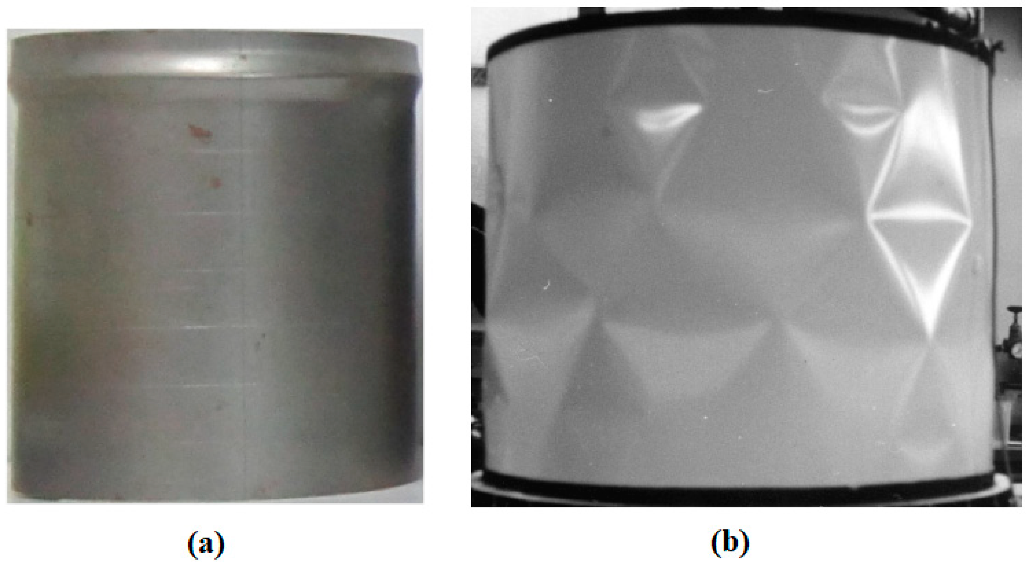
Figure 6.
Design scenarios for stiffened panels: (a) current design scenario and (b) future design scenario [42].
Figure 6.
Design scenarios for stiffened panels: (a) current design scenario and (b) future design scenario [42].
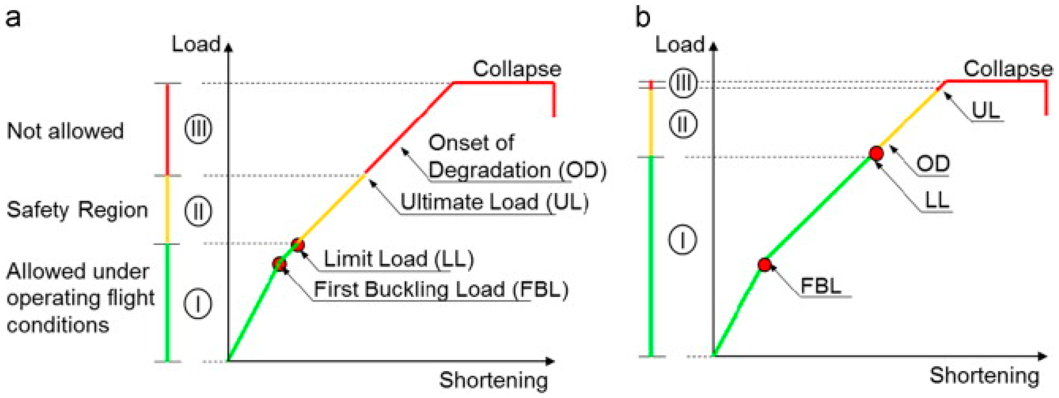
Figure 7.
Structure of (a) FGD vessel and (b) geometry of cone-cylinder transition subjected to axial compression load [44].
Figure 7.
Structure of (a) FGD vessel and (b) geometry of cone-cylinder transition subjected to axial compression load [44].
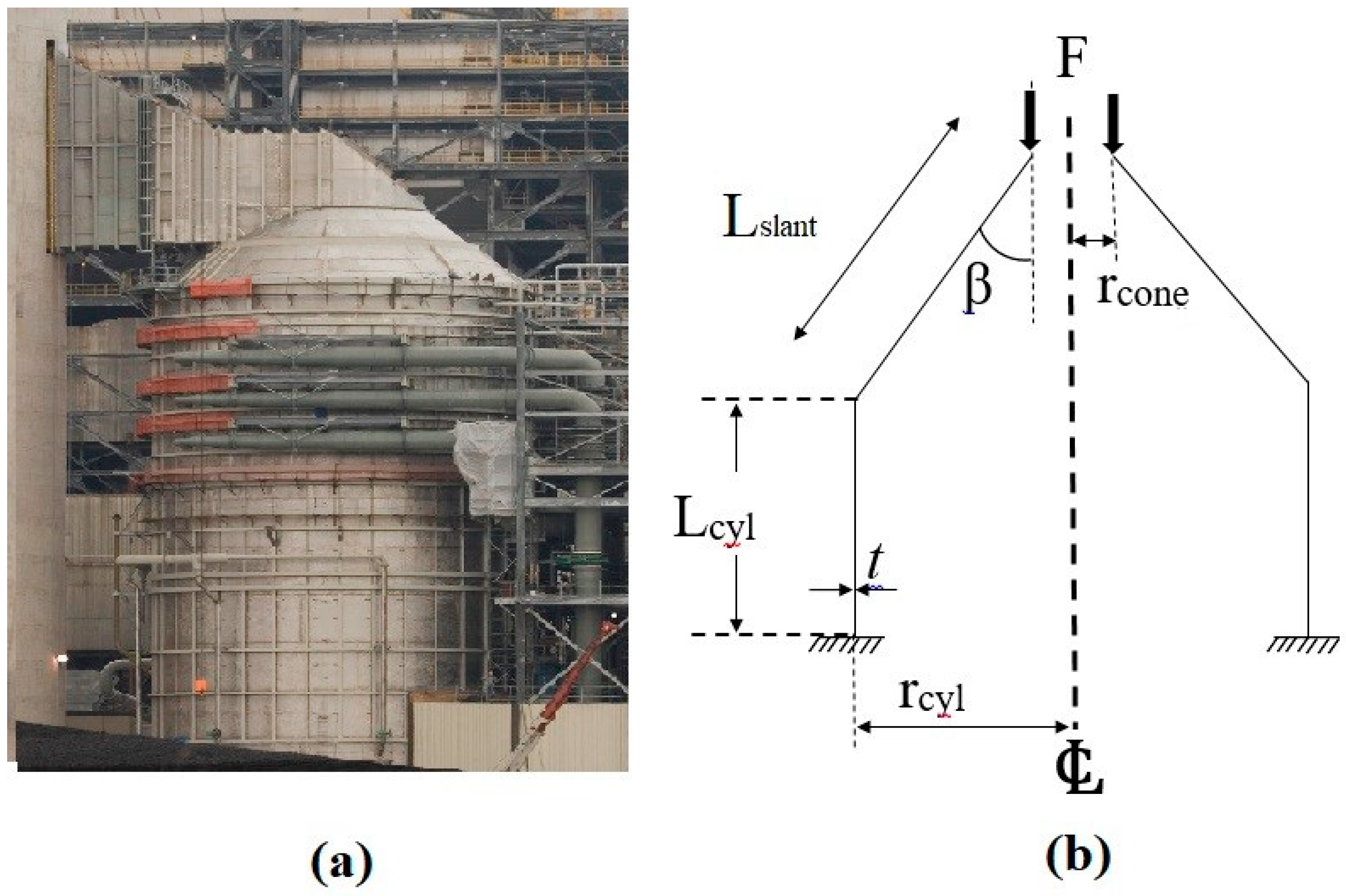
Figure 9.
The stability curve of NASA SP-8007 together with available test data [117].
Figure 9.
The stability curve of NASA SP-8007 together with available test data [117].
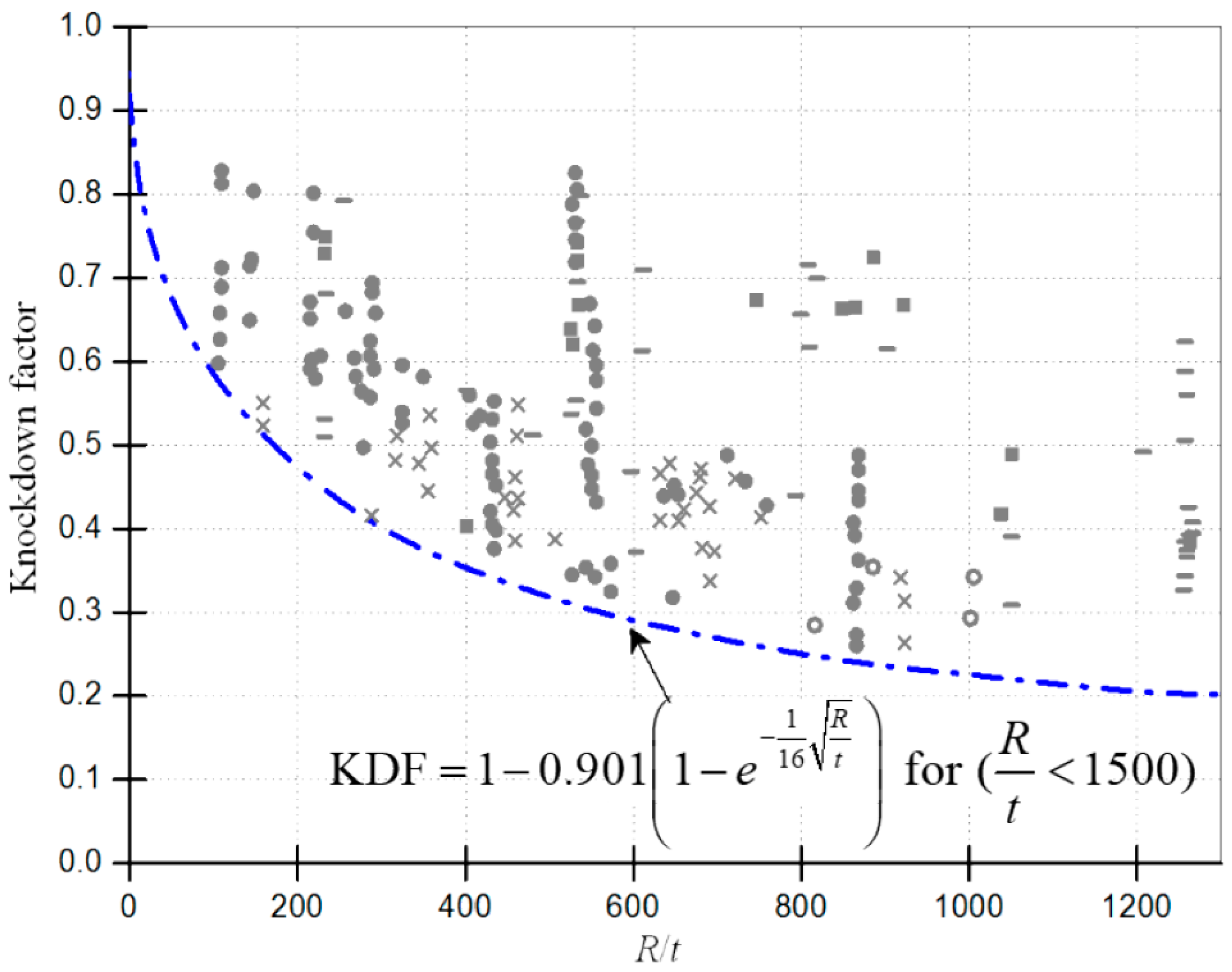
Figure 10.
Schematic diagram of Load and boundary condition of the externally pressurised spherical shell [120].
Figure 10.
Schematic diagram of Load and boundary condition of the externally pressurised spherical shell [120].
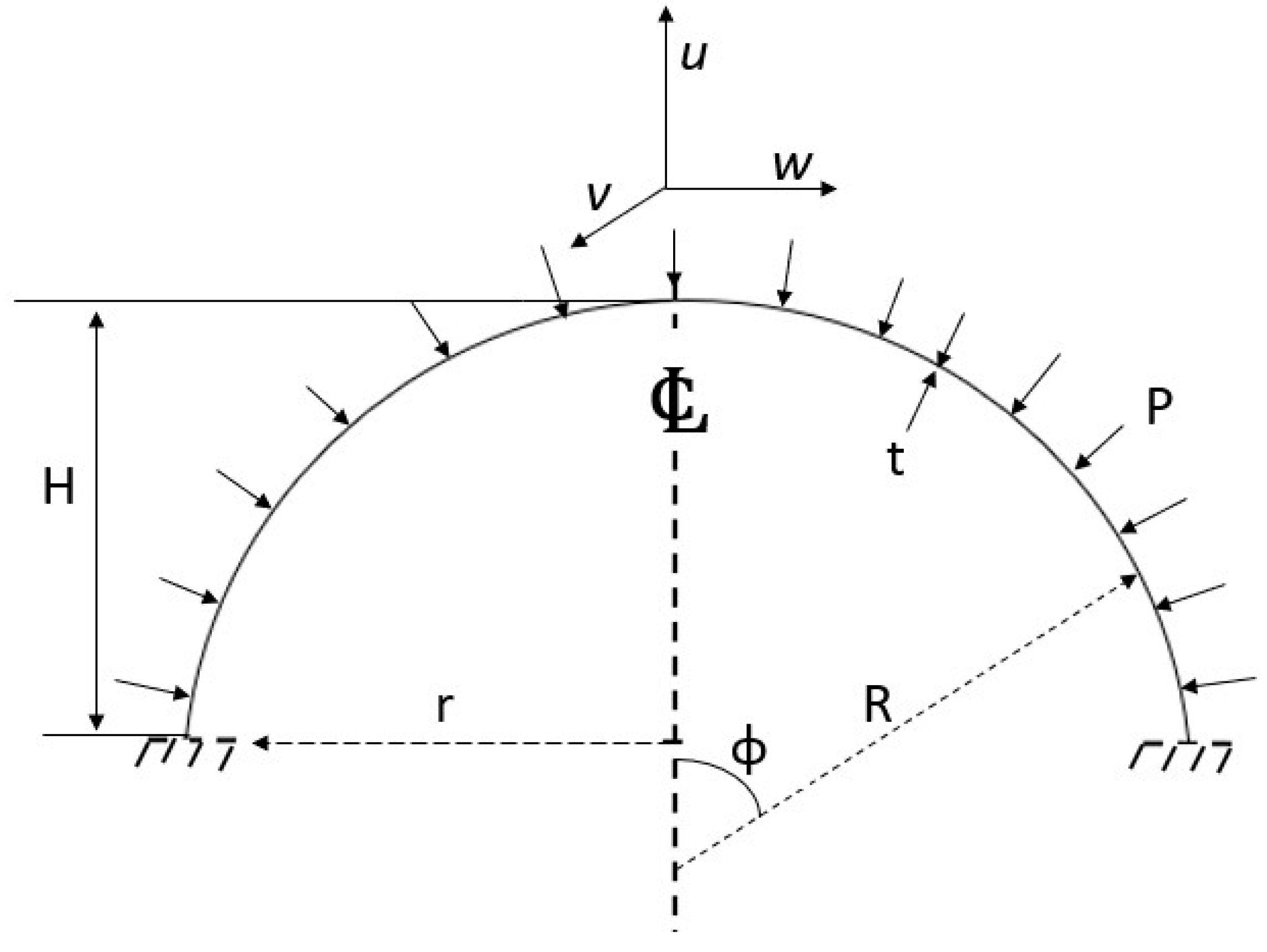
Figure 11.
The example of shell stability curve based on ECCS design guideline [123].
Figure 11.
The example of shell stability curve based on ECCS design guideline [123].

Figure 12.
The experimental results of steel spherical shells subjected to external pressure in the format of PD 5500 [120].
Figure 12.
The experimental results of steel spherical shells subjected to external pressure in the format of PD 5500 [120].
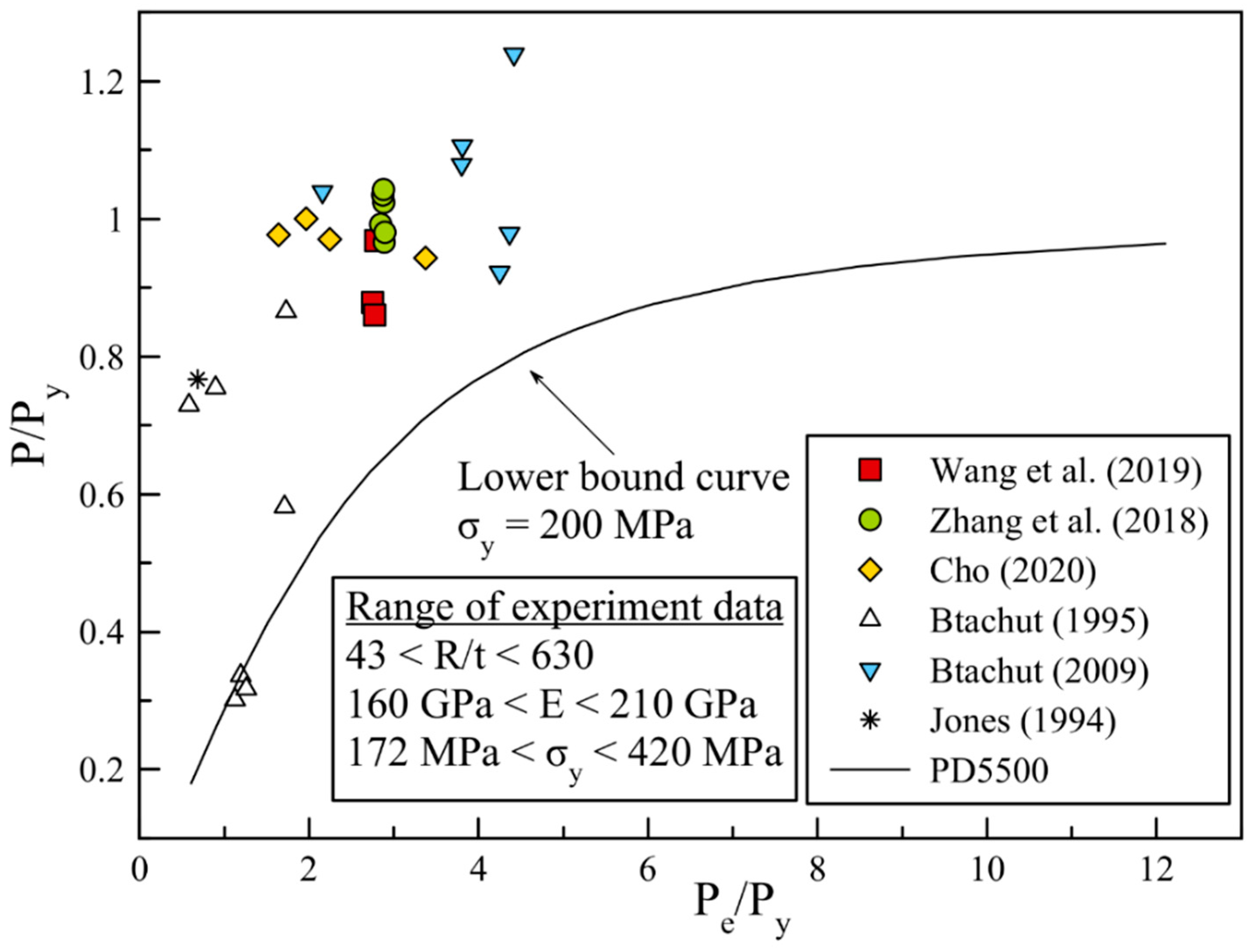
Figure 13.
The experimental results of steel spherical shells subjected to external pressure in the format of ECCS [120].
Figure 13.
The experimental results of steel spherical shells subjected to external pressure in the format of ECCS [120].
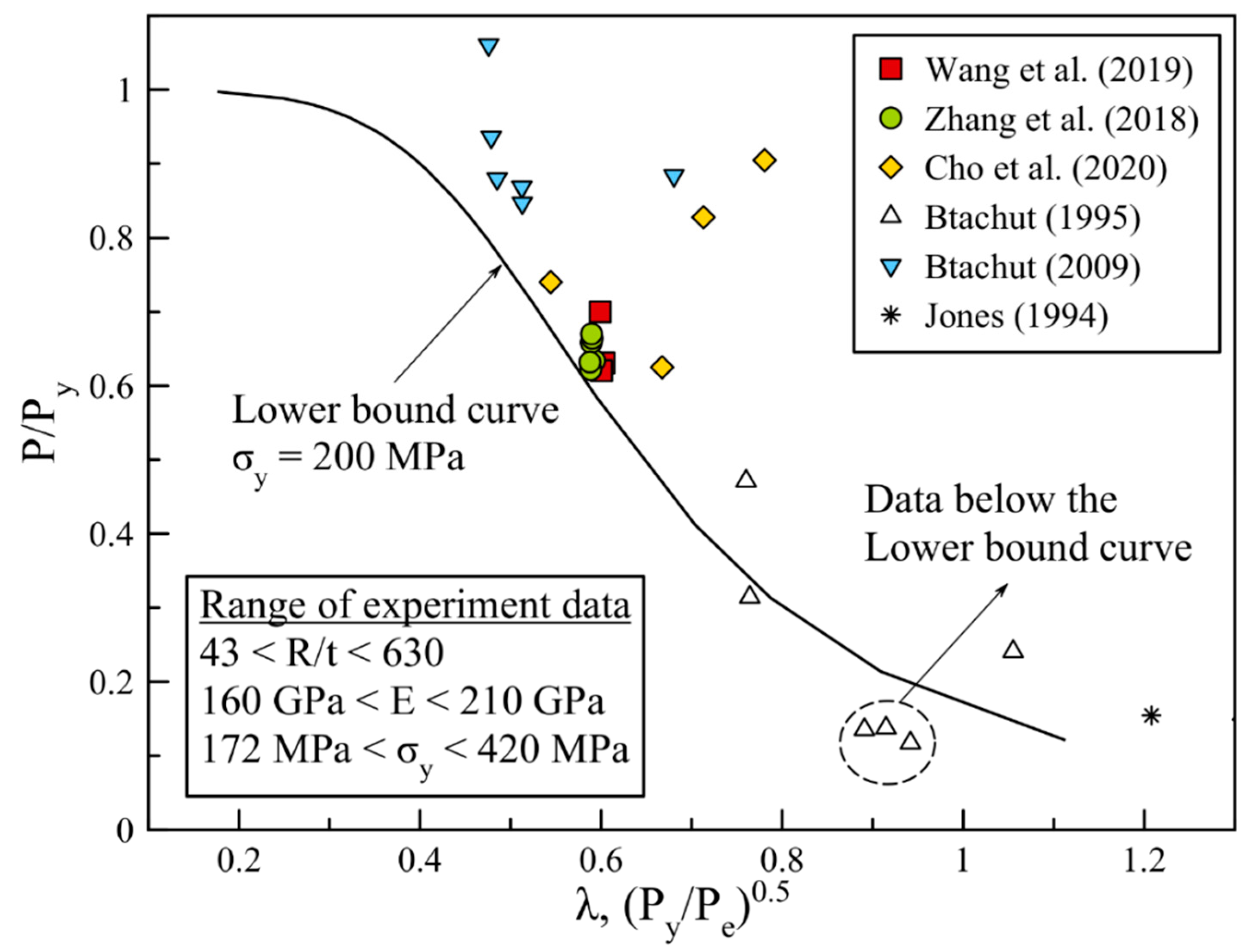
Figure 14.
Comparison of design pressure calculated based on various design guidelines against minimum internal pressure built up inside the tank [32].
Figure 14.
Comparison of design pressure calculated based on various design guidelines against minimum internal pressure built up inside the tank [32].
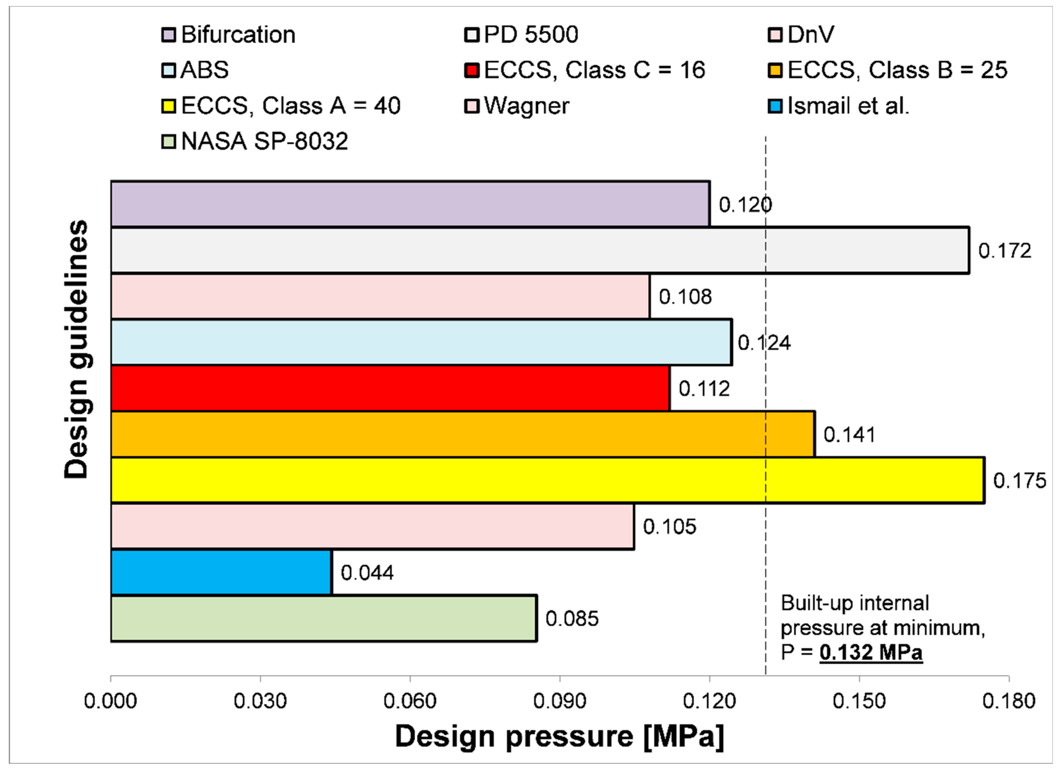
Figure 15.
The knockdown factor of the experimental results versus NASA SP-8032 [133].
Figure 15.
The knockdown factor of the experimental results versus NASA SP-8032 [133].
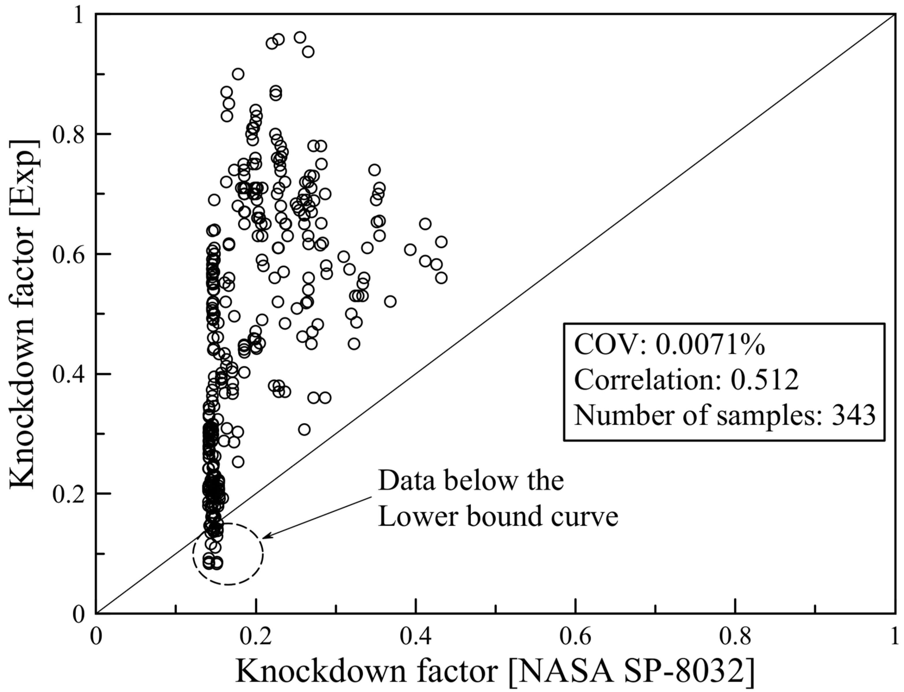
Table 1.
Categories of failure experienced by the vessel [2].
Table 1.
Categories of failure experienced by the vessel [2].
| Categories of failure | Comments |
| Material | Inappropriate choice of material; flaws in the material. |
| Design | Flawed design information; imprecise design techniques; and insufficient shop testing. |
| Fabrication | Inadequate quality control; inappropriate or lacking fabrication techniques such as welding; heat treatment or forming processes methods. |
| Service | Modifications to service conditions by the user; lack of experience among operations or maintenance staff; unexpected situations. Certain services that necessitate particular care in terms of material selection, design specifics, and manufacturing techniques include the followings:
|
Table 3.
Stiffened shell's geometrical tolerance from selected design codes.
| Codes | Imperfection tolerance | |
| Ring-stiffened | Stringer-stiffened | |
| DnV [94] | - | |
| ECCS [49] | , | |
| API [51] | ||
Table 4.
Conclusion of the comparative study.
| Models | Features and recommended application range |
| ABS [125]; DNV [126] |
|
| RS [127]; Galletly and Blachut [128] |
|
| NASA [122]; Wagner et al. [129]; Evkin [130] |
|
Table 5.
Summary of key areas to explore and exploit.
| Area to explore | Proposed Improvement/Control |
| Experimental |
|
| Numerical (FEM) |
|
| Analytical |
|
| Controls variables |
|
Disclaimer/Publisher’s Note: The statements, opinions and data contained in all publications are solely those of the individual author(s) and contributor(s) and not of MDPI and/or the editor(s). MDPI and/or the editor(s) disclaim responsibility for any injury to people or property resulting from any ideas, methods, instructions or products referred to in the content. |
© 2025 by the authors. Licensee MDPI, Basel, Switzerland. This article is an open access article distributed under the terms and conditions of the Creative Commons Attribution (CC BY) license (http://creativecommons.org/licenses/by/4.0/).
Copyright: This open access article is published under a Creative Commons CC BY 4.0 license, which permit the free download, distribution, and reuse, provided that the author and preprint are cited in any reuse.


