Submitted:
28 February 2025
Posted:
05 March 2025
You are already at the latest version
Abstract
The Controller Area Network (CAN) bus has been a cornerstone in vehicular communication, facilitating robust and efficient data exchange among electronic control units (ECUs). This paper provides a comprehensive review of the classical CAN bus, CAN FD, and their key attributes, including message prioritization, arbitration mechanisms, and error detection. Additionally, the paper explores the IEEE 802.11b wireless standard, emphasizing its potential for extending CAN-based networks into wireless domains. The study categorizes existing literature into wired and wireless CAN applications, highlighting advancements, challenges, and limitations in both areas. A critical gap identified in current research is the lack of performance assessment of ECUs, particularly in autonomous vehicle (AV) applications. Moreover, most wireless implementations of CAN rely on Bluetooth, Zigbee, or IEEE 802.11b, which are constrained by limited data rates and scalability. This review outlines the necessity for more integrated, high-performance wireless CAN solutions to enhance vehicular network efficiency, particularly in AV environments.
Keywords:
Controller Area Network (CAN)
; CAN FD
; IEEE 802.11b
; Intra-Vehicle Networks (IVNs)
; Wireless CAN (WCAN)
; Vehicular Communication
; Autonomous Vehicles
; Network Performance
; ECU Integration
Introduction
The Controller Area Network (CAN) bus is a pivotal component in vehicle communication networks and had its roots in the early 1980s. The CAN bus protocol was initially created to address the automotive industry’s needs when vehicles relied on a relatively small number of Electronic Control Units (ECUs) with minimal data processing demands. Over time, as technology has evolved, the CAN bus system now encounters several challenges, including increased weight, higher maintenance costs, the need for unrestricted mobility, and future communication demands [1].
On the other hand, Autonomous Vehicles (AVs) mark a significant transformation in automotive technology. These vehicles require extensive computational power and advanced networking capabilities due to the growing number and sophistication of their ECUs. These ECUs manage critical systems such as LiDAR, radar, cameras, and various sensors—components that continue to increase as AVs incorporate more functionalities. Consequently, this expansion creates a substantial burden on the vehicle’s communication network, necessitating higher data transmission capacity and more complex system integration [2,3].
Real-time applications, such as traffic management, navigation, autonomous driving, toll collection, vehicular communication, vehicle performance review, predictive maintenance, and location-based promotion and advertising, necessitate a high data rate and bandwidth to ensure satisfactory operation and performance.
In light of this situation, it is essential to improve or adapt the conventional CAN bus system to fulfill the evolving demands of autonomous vehicles. One notable solution is the move to wireless system. Switching from wired CAN to wireless CAN (WCAN) can address many of the limitations of a traditional wired CAN bus, such as reducing the physical size of the wiring, reducing costs associated with wiring, and flexibility, However, there are several challenges we will face. Communication through open space is less secure and more open to interference, and there is an increased chance of jamming.
As a result, a major research challenge emerges: bridging the gap between the current capabilities of the CAN bus and the evolving requirements of AV while taking into account ensuring reliability and security in a wireless environment, which is crucial in vehicular communication networks. The objective is to develop a CAN bus system that can support the high data demands and complex networking needs of modern AVs, paving the way for more advanced, efficient, and safer autonomous transportation systems.
The objectives of this review paper are:
- To provide an in-depth review of the CAN bus, including its classical and flexible data-rate (FD) versions.
- To analyze the key components, message arbitration, and error detection mechanisms of CAN networks.
- To compare the performance of CAN against other Intra-Vehicle Networks (IVNs).
- To review the integration of wireless technologies, such as IEEE 802.11b, Bluetooth, and Zigbee, into CAN-based communication.
- To identify gaps in the existing literature, particularly in evaluating the performance of ECUs in autonomous vehicles.
- To highlight future research directions for improving wireless CAN implementations and their scalability.
Controller Area Network (CAN) Types
A. Classical Controller Area Network (CAN) Bus
Bosch introduced the robust communications CAN bus in the early 1980s to optimize communication within vehicles. It provides a standardized approach to facilitate the reliable and efficient transmission of data among controllers, actuators, and sensors to support real-time operations. CAN is a widely adopted protocol for embedded control systems that is compatible with the data link and physical layers of the OSI model and conforms to the ISO11898-1 standard [4,5].
The CAN 2.0 standard, which was introduced by Bosch in 1991, encompassed several variants, including CAN 2.0A featuring an 11-bit identifier and CAN 2.0B featuring a 29-bit identifier. The international community recognized the CAN as standard in 1993 (ISO 11898). Over the subsequent decade, the series received additional standards. In 2012, Bosch introduced CAN FD 1.0, an enhancement to the system through the integration of variable data rates. The 2015-standardized CAN FD permits larger data fields and higher bit sampling in data frames, supporting up to 64 bytes and data rate up to 10 M bps. This is supported by a CRC field that is more compact [4].
In CAN communications, four message formats are utilized: data, remote, error, and overload frames. Information is transmitted within the network through data frames, while remote frames solicit specific data frames. Error and overload frames are transmitted in response to detected errors or a requirement for extended communication time.
- 1.
- Data Frame
Focusing on data frames, as will see in Appendix A, these are composed of information sent from one node to another within the network. A data frame begins with a dominant bit that signifies the Start of Frame (SOF), succeeded by an arbitration field that includes both an identifier and a Remote Transmission Request (RTR). On a network, each message identifier is distinct, indicating the message’s priority and the nature of the information within the data field. The RTR bit determines if the frame’s purpose is for data transmission to other nodes or for requesting transmission [6].
In the context of extended CAN frames, the initial 11 identifier bits conclude with a Substitute Remote Request (SRR) bit to ensure deterministic arbitration resolution between standard and extended frames. This is accompanied by an IDentifier Extension (IDE) bit that differentiates between standard and extended frames when there are two identical series of the prior 11 bits. While standard frames always preempt extended frames due to a dominant IDE bit, an extended frame is recognized by a recessive IDE bit and is followed by 18 bit identifier extension, concluding the arbitration field [6].
A standard frame’s control field consists of six bits, starting with the IDE bit and a reserved bit, whereas in an extended frame, two bits are reserved. The DLC, which follows, indicates the byte count of the data field, which can be up to 64 bytes in CAN FD. Table 1 shows the DLC for CAN and CAN FD frames.

Table 1.
: DLC and data size.
| DLC(decimal) | 0 | 1 | 2 | 3 | 4 | 5 | 6 | 7 | 8 | 9 | 10 | 11 | 12 | 13 | 14 | 15 |
| CAN (byte) | 0 | 1 | 2 | 3 | 4 | 5 | 6 | 7 | 8 | 8 | 8 | 8 | 8 | 8 | 8 | 8 |
| CAN_FD(byte) | 0 | 1 | 2 | 3 | 4 | 5 | 6 | 7 | 8 | 12 | 16 | 20 | 24 | 32 | 48 | 64 |
Following the previous fields are the CRC and Acknowledge (ACK) fields. The CRC, which is 16 bits in length, is a checksum that is utilized to detect errors. The ACK field comprises two bits. One bit is used by the receiver to indicate acknowledgement of a correctly received message by overwriting it as dominant. If an error is detected, the receiver leaves this bit recessive. The other bit serves as a recessive bit delimiter. The frame is terminated by a 7-bit End of Frame (EOF) sequence, followed by three recessive bits that form the Inter-Frame Space (IFS) [7].
- 2.
- Remote Frame
Remote Frame is used to request data such as the data frame but contains no data field itself and uses a recessive RTR bit to signal a request for data.
- 3.
- Error Frame
Error Frame has a distinct format to signal error detection on the bus and triggers protective actions.
- 4.
- Overload Frame
An overload Frame is sent when a node detects an overload situation. It shares similarities with the error frame but it is specifically used to manage timing and processing demands within the network.
Controller Area Network Flexible Data-Rate (CAN FD)
Although the physical layer is similar between the CAN and CAN FD protocols, the data frame format is different in CAN FD and standard CAN. As shown in Appendix A, the control field in the CAN FD frame now contains three additional bits. Bit Rate Switch (BRS) bit enables bit rate switching, while Extended Data Length (EDL) bit (always recessive) defines a CAN FD frame. The arbitration bit rate for CAN and CAN FD frames is identical by definition; however, a recessive BRS bit allows rates greater than 1 Mbps by switching the data phase bit rate to an alternate bit rate. CAN FD’s high performance is demonstrated in two aspects: The message payload size can be up to 64 bytes. Secondly, the data bit rate and the arbitration bit rate can be configured to be different. The data bit rate can reach up to 10 Mbps, while the arbitration bit rate is transmitted at the standard CAN bit rate of up to 1 Mbps [8].
Since the CAN FD frame format is created by utilizing the reserved bits of the standard frame, the implementation requirement guarantees that both CAN FD and CAN nodes can operate on the same network. Furthermore, CAN FD nodes can be integrated into any conventional network with the help of the classical CAN protocol for communication because they employ the industry-standard remote frame format [8].
CAN bus Components and Signals
The CAN network is established through two primary conductors, designated as CAN-L (Low) and CAN-H (High) as shown in Figure 1, which connects the various network components of a vehicle. These conductors transmit signals that, while carrying the same data sequence, exhibit inverted amplitudes to each other. For example, a signal pulse on CAN-H might increase from 2.5 V to 3.75 V, whereas on CAN-L, it would decrease from 2.5 V to 1.25 V, effectively creating a differential signal that enhances noise resistance and data integrity [9].
As detailed in the illustration, the CAN system’s signaling involves two distinct voltage levels to represent binary states: a dominant ’0’ represented by 2.5V and a recessive ’1’ by 0V, where the differential voltage signals the recessive state. This setup comprises three essential components: the CAN Controller, the CAN Transceiver,and the CAN Data Bus Terminal as shown in Figure 2 [5].
The CAN Controller manages the data flow. It both sends and processes information via the CAN Transceiver, which acts as the network’s modulator and demodulator, converting digital signals from the controller into electrical signals for transmission, and vice versa. Finally, the CAN Data Bus Terminal, typically a 120-ohm resistor, is incorporated to prevent signal reflection and echoing along the bus, ensuring clear communication across the network.
Message prioritization
Each message transmission within the CAN network commences with an identifier field, setting the message’s priority. When nodes are ready to transmit, they sequentially push the first segment of their frame onto the network. Here, two scenarios might unfold: [10]
- When a node sends a dominant bit and detects a similar bit on the network (assuming no faults occur), it continues its transmission by sending the subsequent bit.
- If a node sends a recessive bit but detects a dominant bit from another node, it acknowledges a more important message is being transmitted and stops its own transmission.
Figure 2.
CAN bus components.
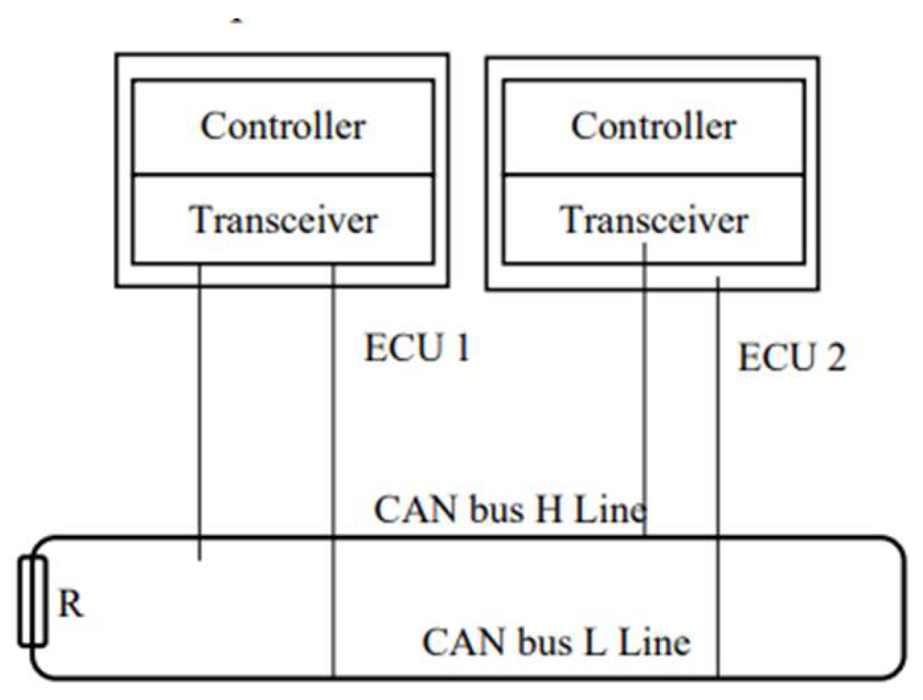
Figure 3.
Arbitration process on CAN bus.
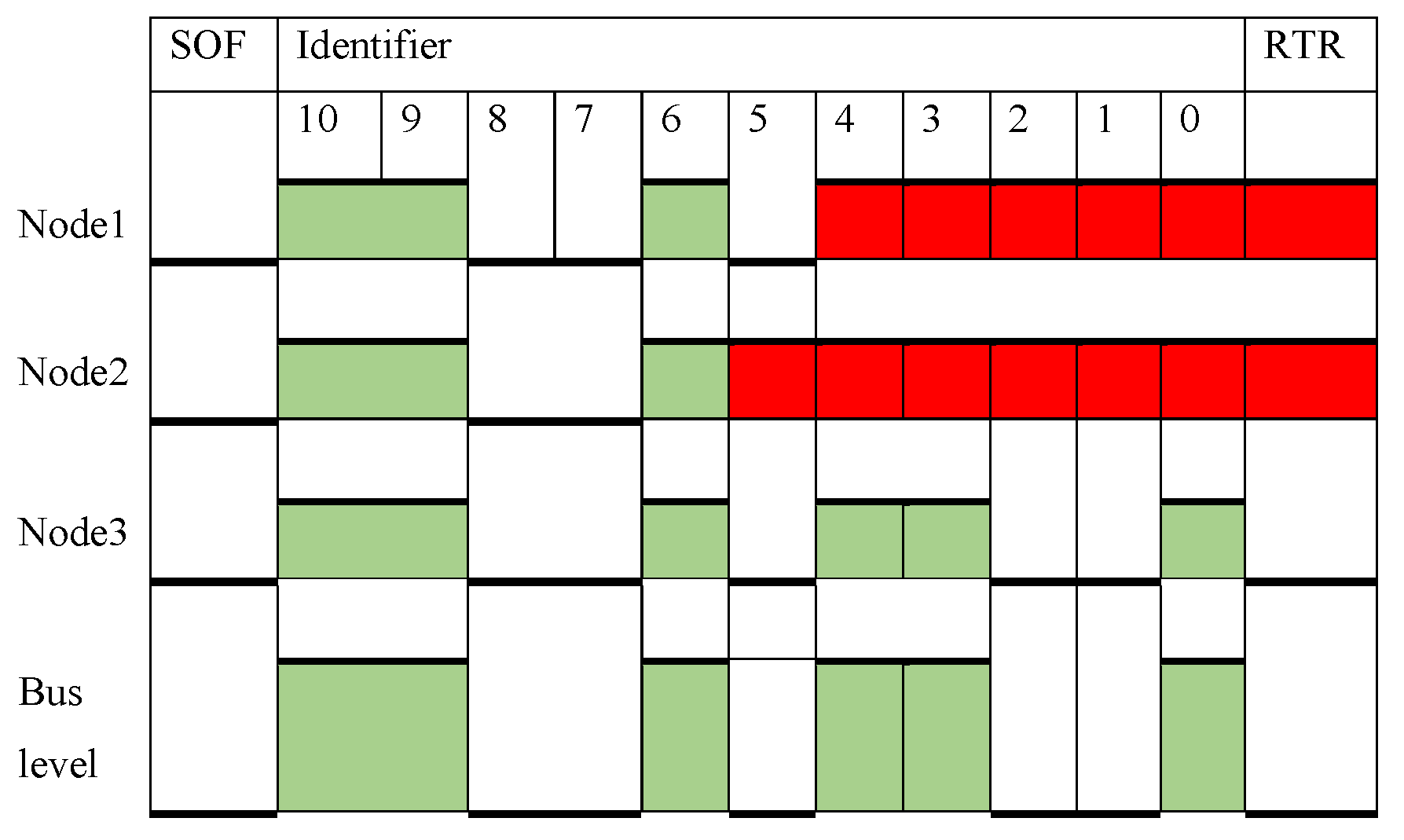
Figure 3 illustrates the arbitration mechanism on a CAN bus, depicting three nodes attempting to transmit data at the same time. Each node presents its message, beginning with a Start of Frame bit, followed by an identifier that determines the message priority, with lower values indicating higher priority. Node 3, with the highest priority , wins the arbitration due to its ability to place dominant bits (logical 0) on the bus, overriding the recessive bits (logical 1) from Nodes 1 and 2 [11].
The arbitration mechanism ensures that the message with the smallest identifier, and thus the highest priority, is successfully transmitted, becoming the sole active sender while others become receivers. This method allows the network to efficiently manage bandwidth by rescheduling messages that didn’t win the arbitration for later transmission, once the current message has been fully sent.
CAN network uniquely allows two frames to share an identifier only in specific cases: one frame is for data transmission and the other for a remote request. The Remote Transmission Request (RTR) bit within the arbitration field ensures that any remote frame ends its transmission if a dominant data frame is present, thus prioritizing data over remote requests.
Message Validation
During transmission, a node will examine each bit sent. If differences between the transmitted and detected bit states are observed, the bit is flagged as erroneous, except in two instances:
1. During the arbitration, if a node sends a recessive bit but detects a dominant bit, indicating a higher priority message, it will halt its transmission.
2. During the acknowledgment slot, the presence of a dominant bit signifies successful message receipt, while a recessive bit indicates a transmission error. A message is considered unacknowledged if a recessive bit is detected during the ACK slot, prompting no receiver node to flag the message as correctly received.
CAN frames are designed with a fixed format and always include a Cyclic Redundancy Check (CRC) to detect transmission errors. If a transmitting node discovers a significant deviation from the expected value, it can signal an error immediately following the problematic bit, except in CRC-related errors, where signaling starts post-ACK delimiter.
Table 1.
: Comparison Between Most Common IVN.
| Bus name | Data rate | Bus features | Access control |
|---|---|---|---|
| CAN | 1 Mbps | Multi-master serial bus protocol | CSMA/CA |
| CAN-FD | 8 Mbps | Similar to classical CAN with longer data payload | CSMA/CA |
| LIN | 20 Kbps | Broadcast serial bus, master-slave communication and cheaper than CAN | Polling |
| FlexRay | 10 Mbps | Multi-master serial bus, 1-master; up to 16 slaves, expensive protocol and 2 channels | TDMA |
| MOST | 150 Mbps | Ring topology, supports 64 devices and very high cost | CSMA/CA TDMA |
| Industrial Ethernet | 100 Mbps | Cheaper than MOST, more expensive than CAN and lightweight wiring and CSMA/CD | TDMA TDD |
To ensure that all nodes recognize an error, the network employs error signaling through error frames, which commence transmission immediately after an error is identified, except for CRC errors which are indicated after the ACK delimiter. This method ensures that any node detecting an error broadcasts an error frame, prompting all nodes to acknowledge the issue, thereby maintaining network reliability and data integrity. Table 1 provides comparison between CAN bus and most common IVN [12].
Literature Review
The previous studies on the CAN bus will be categorized into two sections: the first concerns the wired CAN bus, while the second focuses on the wireless CAN bus.
Wired CAN related works
The research on wired CAN bus can be classified into two main categories. The first category focuses on evaluating the efficiency of the CAN bus, while the second examines its integration with other Intra-Vehicle Networks (IVNs) via a gateway or compares its performance against other IVNs.
Regarding CAN bus performance evaluation, the study in [13] explored CAN with Flexible Data-Rate (CAN FD) and traditional CAN networks. In a simulated network setup, four Electronic Control Units (ECUs) exchanged over 40 messages. The results demonstrated that CAN FD exhibited higher efficiency compared to classical CAN in terms of busload and Worst Case Response Time (WCRT). These simulations were conducted using CANoe (CAN Open Environment) software.
Similarly, the authors in [14] analyzed the transmission times of CAN and CAN FD in a network comprising two ECUs—one dedicated to data transmission and the other to data reception. They found a direct correlation between message size and data bytes, with CAN FD significantly improving the efficiency of large-scale data flashing to the ECU in simulations performed with CANoe.
A study in [15] investigated a CAN FD network transmitting a benchmark message set, established by the Society of Automotive Engineers (SAE), based on both time and event triggers. MATLAB simulations indicated that the CAN FD protocol enhanced real-time control system efficiency by reducing message delay and optimizing bus utilization. Another study in [16] applied Formula SAE standards to evaluate busload and response time in a classical CAN setup, where four electric vehicle ECUs were interconnected. This simulation was executed using CANoe alongside hardware components.
In the agricultural sector, research conducted in [17] employed J1939 and ISO 11783 standards to simulate and analyze network performance for an agricultural machine vehicle. The study compared CAN and CAN FD for data sizes of 8 and 64 bytes, using a simulated setup with three ECUs and a virtual terminal. The findings indicated that CAN FD reduced busload, WCRT, and jitter compared to traditional CAN, with simulations executed in CANoe.
Additionally, the authors in [18] applied queuing analysis to develop analytical models for CAN, CAN FD, and Automotive Ethernet to estimate response times. Their study simulated an 81-message CAN bus that interconnected six ECUs using both CAN and CAN FD protocols. OMNET++ software was utilized for these simulations.
The second research area focuses on integrating a CAN bus with other IVNs via a gateway. The authors in [19] developed three communication protocols—LIN, classical CAN, and FlexRay—along with a gateway protocol facilitating message transfer among them. These protocols were simulated using CANoe hardware. Another study in [20] examined the impact of CAN bus architecture on transmission efficiency, demonstrating that a multi-level-bus CAN network with a gateway improved busload and reduced message delay. This simulation was also performed in CANoe.
When comparing CAN bus performance with other IVNs, the authors in [21] assessed the busload of four ECUs in both ring and star network topologies. The study found that the star topology outperformed the ring topology, with simulations conducted using CANoe. Additionally, in [11], researchers compared latency between FlexRay and CAN bus, concluding that while CAN bus was more suitable for real-time applications, FlexRay excelled in low-priority deterministic data transfer. Hardware-based simulations utilized HSC12 microcontrollers.
Furthermore, in [22], the performance of a classical CAN network was analyzed. The study compared CAN+LIN with classical CAN, showing that CAN exhibited an average transmission speed 2.7% higher than CAN+LIN, based on CANoe simulations. Lastly, the authors in [23] integrated a commercial radar sensor with the CAN bus to simulate and test an autonomous emergency braking system. Their research enabled velocity regulation in self-driving vehicles and allowed trajectory monitoring. The study also measured variations in initial braking positions and stopping distances. Table 2 provided in this study summarizes the relevant papers that propose the examination and modeling of the CAN bus.
Wireless CAN related works
This section is divided into two parts. The first part reviews significant research on implementing Wireless CAN (WCAN) networks using Bluetooth and Zigbee technologies. The second part examines studies focused on Wireless Interworking Units (WIU) and the WCAN network token frame approach. Additionally, the last segment discusses other wireless communication methods, such as gateways or bridges.
Regarding Bluetooth technology, prior research [24] explored the use of Bluetooth modules for vehicle communication. The study highlighted a critical challenge: network latency, which ranges from 10ms to 47ms, posing a concern for time-sensitive applications like engine control. The authors argued that CAN-to-Bluetooth gateways introduce significant processing delays, making them unsuitable for high-speed wireless networks. To address this, they proposed a method that reduces processing delays by framing raw sensor data directly into Bluetooth packets, bypassing traditional CAN frame conversion.
Another study [25] investigated Bluetooth Low Energy (BLE) as a cost-effective and energy-efficient alternative for Vehicular Ad Hoc Networks (VANETs). This approach facilitated communication between sensor nodes and the Electronic Control Unit (ECU). Experimental results showed high packet delivery rates and stable signal strength (RSSI values of at least -10dBm) in both stationary and mobile scenarios. Testing with BLE chipset CC2540/CC2541 demonstrated reduced power consumption, significantly extending battery life.
Additionally, a study [26] proposed a wireless gateway for trucks and trailers with detachable driver cabins. This system utilized a Bluetooth CAN bridge with two transceivers to relay information from the CAN network to a shared wireless link.
In the context of Zigbee, researchers [27] developed a Wireless Controller Area Network (WCAN) for exchanging CAN messages over a wireless medium. They introduced a CAN message-based protocol utilizing Zigbee technology and implemented the system on a FlexDevel board. Their findings confirmed that the system was suitable for real-time control, as demonstrated using the SEA benchmark’s 53 CAN messages.
Another study [28] designed the Hybrid-Backpressure Collection Protocol (Hybrid-BCP) for collecting data from intra-vehicle sensors. This protocol was backward-compatible with CAN bus technology and was built on the Backpressure Collection Protocol (BCP) for wireless sensor networks. The system was tested on Zigbee-based transceivers and demonstrated efficient load balancing and routing. Simulations indicated a 12% improvement in throughput over tree-based data collection protocols while maintaining high packet delivery rates and minimal delay for safety-critical sensors.
Researchers [29] further developed a WCAN protocol for communication between a smart nitrogen oxide (NOx) sensor and the engine control ECU using Zigbee (IEEE 802.15.4) with the XBee module. The Engine Control Module (ECM) was programmed using MATLAB Simulink to receive sensor data, calculate O2% and NOx parts per million (ppm) values, and display the information on a monitor. The performance of this setup was compared with Wi-Fi, LoRa, and BLE technologies.
Several studies [30,31,32,33] examined the integration of WIU in CAN networks, aiming to extend CAN segments using IEEE 802.11b WLAN. The WIU facilitated communication between remote CAN 2.0A nodes by encapsulating CAN messages within IEEE 802.11b packets. Another study [31] proposed a WIU-based system utilizing an IEEE 802.16-based wireless metropolitan area network (MAN) to connect multiple CAN segments, employing an encapsulation technique for seamless data transmission.
The WCAN token frame method allows nodes to share a broadcast channel by sequentially transmitting data within a designated timeframe. One study [34] implemented a WCAN based on a token ring protocol to minimize collisions and improve communication efficiency. Simulations using the QualNet platform demonstrated reduced latency and enhanced packet delivery rates.
Further research [35] applied the Wireless Token Ring Protocol (WTRP) in a network of 20 nodes, using a medium access control (MAC) protocol optimized for wireless communication. The token frame approach ensured controlled channel access and reduced retransmissions due to collisions. QualNet simulations showed superior performance compared to IEEE 802.11 in ring network environments.
A separate study [36] simulated a simple wireless transceiver with three nodes. The transmitter node accessed the channel every 100ms to send data frames using Carrier Sense Multiple Access/Non-Destructive Arbitration (CSMA/NDA) and On-Off Keying (OOK) modulation. Data transmission was performed via Amplitude Shift Keying (ASK) at 433 MHz with a 20 kbps bit rate.
Another study [37] developed a point-to-point wireless system for bridging remote CAN buses. The research utilized a CAN-to-RF platform with an STM32F103RC Cortex-M3 microcontroller and a TI CC2500 radio module operating at 2.4 GHz. The system simulated seven nodes with varied packet transmission intervals.
Lastly, researchers [38] designed a WCAN system comprising three hardware components: a pedal-integrated body controller acting as a gateway, a cluster unit, and a digital tachometer. Communication was facilitated via a wireless platform incorporating an ACM Cortex-M3 microcontroller and a TI CC2520 low-power radio. This platform supported direct wired connections to a local CAN unit. Table 3 provides a summary of key studies on wireless CAN networking.
MATHEMATICAL MODEL FOR AV COMMUNICATION BUSES
To analyze the performance of different communication buses in AVs, a mathematical model is proposed. This model evaluates key performance metrics such as bus utilization, worst-case response time (WCRT), message latency, packet delivery ratio (PDR), and throughput.
Bus Utilization
Bus utilization (U) represents the percentage of time the bus is occupied with message transmissions relative to the total cycle time. It is given by [39,40,41,42,43,44,45,46]:
U = (sum(T_i) / T_cycle) * 100%
Table 3.
Summary of Existing papers on Wireless CAN Bus.
| Ref | Application | Wireless Technology | Research Tool | Contribution and Strength | Shortcoming |
|---|---|---|---|---|---|
| [16] | Vehicle | Bluetooth | CANBLUE module and CANalyzer | Developed a gateway to convert CAN messages to Bluetooth format using the CANBLUE module. | CAN to Bluetooth gateways are unsuitable for vehicle high-speed wireless networks, no dealing with anti-jamming |
| [17] | Vehicle | Bluetooth | Texas instrument development kit CC2540/CC2541 | Utilized BLE for cost-effective and energy-efficient communication between sensor nodes and the ECU. | Limited data rate not exceed 1 Mbps, no dealing with anti-jamming. |
| [18] | Trucks and Trailers | Bluetooth | DAVE v4 NINA-B1 | Implemented a wireless CAN bridge integrated with the AddVolt network for vehicular refrigeration systems. | Throughput metric not mentioned. In addition, limited data rate |
| [19] | Real-time control applications | ZigBee | XCTU software | Enabled CAN message exchange wirelessly by developing WCAN on FlexDevel board. | Zigbee technology limits data rate, simulate five nodes. ,no dealing with anti-jamming |
| [20] | Vehicle | ZigBee | Lyapunov Optimization Theorem | Designed the Hybrid-Backpressure Collection Protocol to enhance intra-car sensor data collection. | limited data rate |
| [21] | Heavy Duty Vehicles | ZigBee | XBee module | Created a WCAN protocol to link NOx sensors with the vehicle’s engine control unit. | Zigbee technology limits data rate, so WCAN is only between two nodes. ,no dealing with anti-jamming |
| [22] | Industrial control applications | IEEE 802.11 WLAN | OPNET Modeler | Extended CAN segments by utilizing IEEE 802.11 WLAN via WIU | Limited data rate, ,no dealing with anti-jamming |
| [27] | General | 802.11b Token Ring | QualNet simulator. | Implemented a Wireless CAN (WCAN) based on the wireless token ring protocol for multiple nodes. | scalability and complexity constraints, ,no dealing with anti-jamming. |
| [28] | Industrial | On-off Keying | On-Off Keying modulation | Developed a simple wireless transceiver that was compatible with CAN controllers. | Data rate is limited to 125 k bps, ,no dealing with anti-jamming |
| [29] | Vehicle | bridge | STM32F103RC Cortex-M3 microcontroller | Designed and validated the CAN-to-RF platform connected to real cluster units to generate speed and RPM data. | The number of relays and data rate supported by the designed ViCAN depends on wireless excess latency,no dealing with anti-jamming |
| [30] | Vehicle | gateway | Hardware with CANoe | demonstrated a functional prototype of the body controller and gateway of a vehicle interacting with a digital tachometer and cluster. | Limited data rate, no dealing with anti-jamming |
where T_i is the transmission time of message i, and T_cycle is the total cycle time of the bus.
Worst-Case Response Time (WCRT)
WCRT accounts for the queuing delay, transmission time, and interference from higher-priority messages. It is expressed as [39,40,41,42,43,44]:
WCRT = J + C + I
where J is the queuing delay, C is the transmission time, and I is the interference delay from higher-priority messages.
Message Latency
Message latency (τ) is the time required to transmit a message over the bus. It is calculated as [39,40,41,42,43,44,45,46]:
τ = L / R
where L is the message length in bits, and R is the data rate of the bus in Mbps.
Packet Delivery Ratio (PDR)
PDR quantifies the reliability of message transmission by measuring the fraction of successfully received packets relative to the total sent packets [39,40,41,42,43,44,45,46]:
PDR = (Received Packets / Sent Packets) * 100%
Throughput
Throughput (T) measures the amount of successfully delivered data over a given time period and is defined as [39,40,41,42,43,44]:
T = sum(D_i) / T_obs
where D_i represents the data successfully delivered by message i, and T_obs is the total observation time.
Performance Comparison
To illustrate the differences in performance among various AV bus technologies, Table 4 presents the calculated values for key metrics based on theoretical and experimental data. The results indicate that CAN FD and IEEE 802.11b outperform classical CAN in terms of reduced latency, higher throughput, and improved efficiency. However, wireless implementations such as IEEE 802.11b introduce potential security vulnerabilities and interference challenges that must be addressed in real-time AV applications.
Conclusions
This review has examined the evolution and technical aspects of CAN and CAN FD networks while addressing their integration with wireless technologies like IEEE 802.11b, Bluetooth, and Zigbee. Existing studies have focused on measuring network efficiency, message delays, and busload comparisons but have largely overlooked the performance evaluation of ECUs, particularly in AV applications. Wireless extensions of CAN, though promising, suffer from limitations in data rate and scalability. Future research should focus on developing high-speed, low-latency wireless CAN frameworks that integrate seamlessly with advanced vehicular networks. Enhanced wireless ECU extensions and optimized inter-networking methods will be critical in advancing next-generation vehicular communication systems.
References
- Bozdal, M., Samie, M., and Jennions, I. "A Survey on Can Bus Protocol: Attacks, challenges, and potential solutions." 2018 International Conference on Computing, Electronics and Communications Engineering (iCCECE). IEEE, 2018. [CrossRef]
- Leigh, B., and Duwe, R. "Designing Autonomous Vehicles for a Future Of Unknowns." ATZelectronics worldwide vol.16 no.3 (2021): pp. 44-47.
- Sharma, R., “Big Data for Autonomous Vehicles,” in Studies in Computational Intelligence, vol. 945, Springer Science and Business Media Deutschland GmbH, 2021, pp. 21–47. [CrossRef]
- Boland, H. M., Burgett, M. I., Etienne, A. J., and Stwalley III, R. M. "An Overview of CAN-BUS Development, Utilization, and Future Potential in Serial Network Messaging for Off-Road Mobile Equipment." Technology in Agriculture (2021). [CrossRef]
- Bozdal, M., Samie, M., Aslam, S., and Jennions, I. “Evaluation of CAN Bus Security Challenges,” Sensors (Switzerland), vol. 20, no. 8, p.2364, MDPI AG, Apr. 02, 2020. [CrossRef]
- Di Natale, M., Zeng, H., Giusto, P., and Ghosal, A. “Understanding and Using the Controller Area Network Communication Protocol: Theory and Practice”. Springer Science and Business Media, 2012.
- Chowdhury, M., and Dey, K. “Intelligent transportation systems-a frontier for breaking boundaries of traditional academic engineering disciplines [Education],” IEEE Intelligent Transportation Systems Magazine, vol. 8, no. 1, pp. 4–8, Mar. 2016. [CrossRef]
- Hartwich, F. "CAN with Flexible Data-Rate." In Proc. iCC, pp. 1-9. Citeseer, 2012.
- Cataldo, C. "Ethernet Network in the Automotive field: Standards, possible approaches to Protocol Validation and Simulations." Hamburg University of Applied Sciences ,PhD diss., Politecnico di Torino, 2021.
- De Andrade, R., Hodel, K. N., Justo, J. F., Laganá, A. M., Santos, M. M., and Gu, Z. “Analytical and Experimental Performance Evaluations of CAN-FD Bus,” IEEE Access, vol. 6, pp. 21287–21295, Apr. 2018. [CrossRef]
- Hafeez, A., Malik, H., Avatefipour, O., Rongali, P. R., and Zehra, S. “Comparative Study of CAN-Bus and FlexRay Protocols for In-Vehicle Communication,” in SAE Technical Papers, SAE International, Mar. 2017. [CrossRef]
- Bernardini, C., Asghar, M. R., and Crispo, B. “Security and privacy in vehicular communications: Challenges and opportunities,” Vehicular Communications, vol. 10. Elsevier Inc., pp. 13–28, Oct. 01, 2017. [CrossRef]
- Cheon, B., and Jeon, J. W. "The CAN FD Network Performance Analysis using the CANoe." In IEEE ISR 2013, pp. 1-5. IEEE, 2013. [CrossRef]
- Nguyen, T. H., Cheon, B. M., and Jeon, J. W. "CAN FD performance analysis for ECU re-programming using the CANoe." In The 18th IEEE International Symposium on Consumer Electronics (ISCE 2014), pp. 1-4. IEEE, 2014. [CrossRef]
- Tenruh, M., Oikonomidis, P., Charchalakis, P., and Stipidis, E. "Modelling, Simulation, and Performance Analysis of a CAN FD system with SAE Benchmark Based Message Set." Proc. 15th Int. CAN Conf. 2015. pp. 12-19.
- Vemparala, M. R., Yerabati, S., and Mary, G. I. "Performance Analysis of Controller Area Network Based Safety System in an Electric Vehicle." 2016 IEEE International Conference on Recent Trends in Electronics, Information and Communication Technology (RTEICT). IEEE, 2016. (pp. 461-465. [CrossRef]
- Zago, G. M., and de Freitas, E. P. “A Quantitative Performance Study on CAN and CAN FD Vehicular Networks,” IEEE Transactions on Industrial Electronics, vol. 65, no. 5, pp. 4413–4422, May 2018. [CrossRef]
- Kim, H., Yoo, W., Ha, S., and Chung, J. M. “In-Vehicle Network Average Response Time Analysis for CAN-FD and Automotive Ethernet,” IEEE Trans Veh Technol, vol. 72, no. 6, pp. 6916–6932, Jun. 2023. [CrossRef]
- Rishvanth, D. V., and Ganesan, K. “Design of an In-Vehicle Network (Using LIN, CAN and FlexRay), Gateway and its Diagnostics Using Vector CANoe,” American Journal of Signal Processing, vol. 1, no. 2, pp. 40–45, Feb. 2012. [CrossRef]
- Yong, S., Ma, Y., Zhao, Y., and Qi, L."Analysis of the Influence of CAN Bus Structure on Communication Performance." In IoT as a Service: 5th EAI International Conference, IoTaaS 2019, Xi’an, China, November 16-17, 2019, Proceedings 5, pp. 405-416. Springer International Publishing, 2020.
- Hegde, R., Kumar, S., and Gurumurthy, K. “The Impact of Network Topologies on the Performance of the In-Vehicle Network” International Journal of Computer Theory and Engineering, vol. 5, no. 3, pp. 405–409, 2013. [CrossRef]
- Ishak, M. K., Ali, O., Sirajuduin, E. A., and Qi, L. S. “Vehicle Sensors Programming Based On Controller Area Network (CAN) Bus Using Canoe,” In 2019 16th International Conference on Electrical Engineering / Electronics, Computer, Telecommunications and Information Technology (ECTI-CON), pp. 1-4. IEEE, 2019.
- Kim, J., Jung, W. Y., Kwon, S., and Kim, Y. “Performance test of autonomous emergency braking system based on commercial radar,” in Proceedings - 2016 5th IIAI International Congress on Advanced Applied Informatics, IIAI-AAI 2016, Institute of Electrical and Electronics Engineers Inc., Aug. 2016, pp. 1211–1212. [CrossRef]
- Reddy, A. D. G., Dhadyalla, G., and Kumari, N. "Experimental validation of CAN to Bluetooth gateway for in-vehicle wireless networks." 2013 International Conference on Emerging Trends in Communication, Control, Signal Processing and Computing Applications (C2SPCA). pp. 1-5. IEEE, 2013. [CrossRef]
- Mirza, N., and Khan, A. N. “Bluetooth Low Energy based Communication Framework for Intra Vehicle Wireless Sensor Networks,” in Proceedings - 2017 International Conference on Frontiers of Information Technology, FIT 2017, Institute of Electrical and Electronics Engineers Inc., Jul. 2017, pp. 29–34. [CrossRef]
- Almeida, P. M. M. “Wireless CAN bus bridge,” Master thesis, University of Porto , Jule, 2019.
- Mary, G. I., and Alex, Z. C. “Implementation and response time analysis of messages in Wireless Controller area Network,” Indian J Sci Technol, vol. 8, no. 8, pp. 536–541, 2015. [CrossRef]
- Si, W., Starobinski, D., and Laifenfeld, M. “A Robust Load Balancing and Routing Protocol for Intra-Car Hybrid Wired/Wireless Networks,” IEEE Trans Mob Comput, vol. 18, no. 2, pp. 250–263, Feb. 2019. [CrossRef]
- Siemuri, A., Glocker, T., Mekkanen, M., Kauhaniemi, K., Mantere, T., and Elmusrati, M. “Design and implementation of a Wireless CAN Module For Marine Engines Using Zigbee Protocol,” IET Communications, vol. 17, no. 13, pp. 1541–1552, Aug. 2023. [CrossRef]
- Bayilmis, C., Erturk, I., and Ceken, C. “Extending CAN segments with IEEE 802.11 WLAN”. In The 3rd ACS/IEEE International Conference on Computer Systems and Applications, January ,2005. (p. 79). IEEE. [CrossRef]
- Patil R. D., and Shinde, V. D. “ Design and Implementation of WIU for CAN/WLAN/CAN Bridge” International Journal Of Innovative Research In Technology,IJIRT , 2015, Vol. 1 Issue 12.
- Purohit, M., Vyas, P., and Bora, A. "Evaluation of MAC Protocols Using Local Bridge in High Frequency Bands Based on Discrete Event Simulator Tool Using Analytical Approach." In 2017 International Conference on Energy, Communication, Data Analytics and Soft Computing (ICECDS), pp. 2103-2107. IEEE, 2017.
- Ozcelik, I. “Interconnection of CAN segments through IEEE 802.16 wireless MAN,” Journal of Network and Computer Applications, vol. 31, no. 4, pp. 879–890, Nov. 2008. [CrossRef]
- Mary, G. I., Alex, Z. C., and Jenkins, L. “Real Time Analysis of Wireless Controller Area Network” ICTACT Journal on Communication Technology, vol. 05, no. 03, pp. 951–958, Sep. 2014. [CrossRef]
- Mary, G. I., and Alex, Z. C. "Modelling, Analysis and Validation of Wireless Controller Area Network." International Journal of Engineering Systems Modelling and Simulation 8, no. 1 (2016): pp. 8-19. [CrossRef]
- Quitin, F. and Osee, M. “A Wireless Transceiver for Control Area Networks: Proof-of-Concept Implementation,” in IEEE International Workshop on Factory Communication Systems - Proceedings, WFCS, Institute of Electrical and Electronics Engineers Inc., pp. 1-4. IEEE, 2023. [CrossRef]
- Park, J., Lee, C., Park, J. H., Choi, B. C., and Ko, J. G. "Poster: Exploiting Wireless CAN Bus Bridges for Intra-Vehicle Communications." In 2014 IEEE Vehicular Networking Conference (VNC), pp. 111-112. IEEE, 2014.
- Lee, C., Jeong, H., Ryu, J., Choi, B. C., and Ko, J. “Demo abstract: Bringing Down Wires in Vehicles - Interconnecting ECUs Using Wireless Connectivity,” in SenSys 2015 - Proceedings of the 13th ACM Conference on Embedded Networked Sensor Systems, Association for Computing Machinery, Inc, Nov. 2015, pp. 465–466. [CrossRef]
- Q. I. Ali, "Design, implementation & optimization of an energy harvesting system for VANETs’ road side units (RSU)," IET Intelligent Transport Systems, vol. 8, no. 3, pp. 298-307, 2014.
- Q. I. Ali, "An efficient simulation methodology of networked industrial devices," in Proc. 5th Int. Multi-Conference on Systems, Signals and Devices, 2008, pp. 1-6.
- Q. I. Ali, "Security issues of solar energy harvesting road side unit (RSU)," Iraqi Journal for Electrical & Electronic Engineering, vol. 11, no. 1, 2015.
- Q. I. Ali, "Securing solar energy-harvesting road-side unit using an embedded cooperative-hybrid intrusion detection system," IET Information Security, vol. 10, no. 6, pp. 386-402, 2016.
- Q. Ibrahim, "Design & Implementation of High-Speed Network Devices Using SRL16 Reconfigurable Content Addressable Memory (RCAM)," Int. Arab. J. e Technol., vol. 2, no. 2, pp. 72-81, 2011.
- M. H. Alhabib and Q. I. Ali, "Internet of autonomous vehicles communication infrastructure: a short review," Diagnostyka, vol. 24, 2023.
- Q. I. Ali, "Realization of a robust fog-based green VANET infrastructure," IEEE Systems Journal, vol. 17, no. 2, pp. 2465-2476, 2022.
- Q. I. Ali and J. K. Jalal, "Practical design of solar-powered IEEE 802.11 backhaul wireless repeater," in Proc. 6th Int. Conf. on Multimedia, Computer Graphics and Broadcasting, 2014.
Figure 1.
CAN-L and CAN-H output signal.
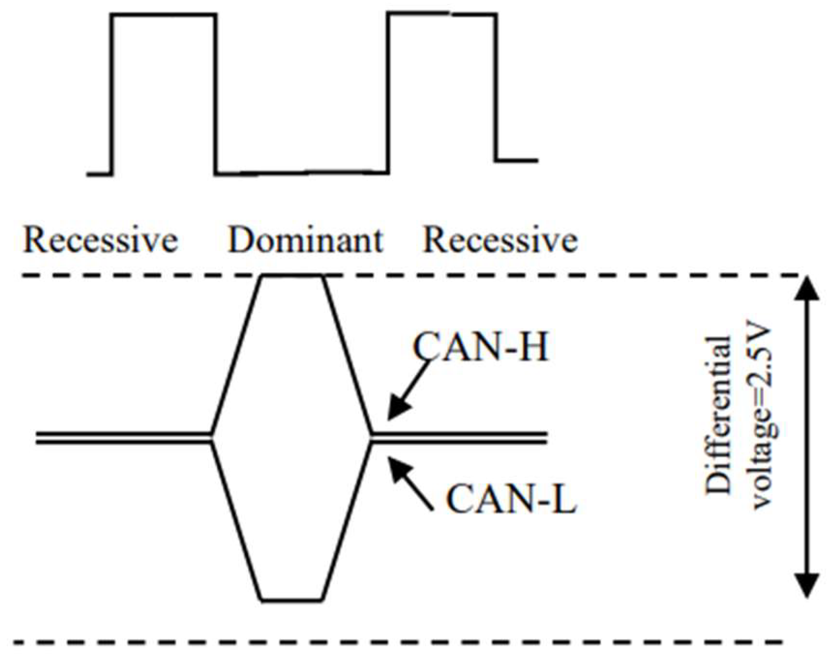
Table 2.
Summary of Existing papers on Wired CAN Bus.
| Ref | Application | Research Tool |
Contribution and Strength | Shortcoming |
|---|---|---|---|---|
| [13] | General Application | CANoe | The study examined CAN-FD-8-byte and CAN networks, where four ECUs exchanged over 40 messages in a simulated environment. Results indicated that CAN-FD outperformed CAN in terms of network message busload and worst-case response time (WCRT). |
It dealt with limited number of ECUs, few messages. It did not simulate external ECUs |
| [14] | Automative | CANoe | To compare transmission efficiency, the researchers measured the bus transmission times of CAN and CAN FD within a network consisting of two ECUs—one for sending and one for receiving data. A correlation was identified between message count and data bytes, with CAN FD demonstrating superior performance, particularly when flashing large amounts of data to the ECU. |
It dealt with limited number of ECUs. It did not simulate external ECUs |
| [15] | Industrial Applications | MATLAB | The performance of a CAN FD network transmitting a time- and event-based SAE benchmark message set was assessed. Simulation results showed that the CAN FD protocol enhanced real-time control system message delay and improved bus utilization. | It did not simulate external ECUs |
| [16] | Electrical vehicle | CANoe Hardware | For an electric vehicle setup, FSAE standards were used to assess busload and response time across four ECUs. | It dealt with limited number of ECUs. It did not simulate external ECUs. In addition, it did not handle CAN FD |
| [17] | Agriculture Machine | CAN oe | A separate study simulated and analyzed an agricultural machine vehicle network using J1939 and ISO 11783 standards to compare CAN and CAN FD performance with both 8-byte and 64-byte messages. The simulated network included three ECUs and a virtual terminal, with results indicating that CAN FD exhibited lower busload, WCRT, and jitter than CAN. | It dealt with limited number of ECUs. It did not simulate external ECUs |
| [18] | Vehicle | OMNeT++ | Response time estimation was conducted using queuing analysis-based models for CAN, CAN-FD, and Automotive Ethernet. The analytical model featured an 81-message CAN bus connecting six ECUs within both CAN and CAN FD networks. | It dealt with limited number of ECUs. It did not simulate external ECUs |
| [19] | Vehicle | CANoe Hardware | In another study, researchers developed three communication protocols—LIN, classical CAN, and FlexRay—along with a gateway protocol to facilitate message transfers between them. |
It dealt with limited number of ECUs. It did not simulate external ECUs. In addition, it did not handle CAN FD |
| [20] | Vehicle | CANoe | The impact of CAN bus structure on transmission performance was investigated. A multi-level bus CAN network incorporating a gateway was found to reduce both busload and message delay in simulations. |
It did not simulate external ECUs. In addition, it did not handle CAN FD |
| [21] | Vehicle | CANoe | the study compared ring and star network topologies by evaluating busload across four ECUs. Findings revealed that the star topology outperformed the ring topology. |
It dealt with limited number of ECUs. It did not simulate internal ECUs . In addition, it did not handle CAN FD |
| [11] | Vehicle | HCS12 microcontrollers | FlexRay and CAN-Bus latencies were compared, showing that while CAN-Bus is better suited for hard real-time systems, FlexRay offers advantages for low-priority deterministic data transmission. | It dealt with limited number of ECUs. It did not simulate internal ECUs . In addition, it did not handle CAN FD |
| [22] | Vehicle | CANoe | The classical CAN network was analyzed, and when compared to the classical CAN+LIN setup, it was found to have a 2.7% higher average transmission speed. | It dealt with limited number of ECUs. It did not simulate internal ECUs. In addition, it did not handle CAN FD |
| [23] | AV | Commercial radar | The emergency braking system was simulated and tested by integrating a radar sensor with the CAN bus. This setup enabled control over an autonomous vehicle’s speed and movement tracking. The study measured braking starting position errors and braking distances to assess system performance. | It dealt with limited number of ECUs. It did not simulate internal ECUs . In addition, it did not handle CAN FD |
Table 4.
Performance Comparison of AV Communication Buses.
| Bus Type | Data Rate (Mbps) | Bus Utilization (%) | WCRT (ms) | Latency (ms) | PDR (%) | Throughput (kbps) |
| CAN 2.0 | 1 | 75 | 12 | 10 | 95 | 800 |
| CAN FD | 8 | 60 | 6 | 2 | 98 | 5000 |
| IEEE 802.11b | 11 | 40 | 2 | 1.5 | 90 | 7500 |
Disclaimer/Publisher’s Note: The statements, opinions and data contained in all publications are solely those of the individual author(s) and contributor(s) and not of MDPI and/or the editor(s). MDPI and/or the editor(s) disclaim responsibility for any injury to people or property resulting from any ideas, methods, instructions or products referred to in the content. |
© 2025 by the authors. Licensee MDPI, Basel, Switzerland. This article is an open access article distributed under the terms and conditions of the Creative Commons Attribution (CC BY) license (http://creativecommons.org/licenses/by/4.0/).
Copyright: This open access article is published under a Creative Commons CC BY 4.0 license, which permit the free download, distribution, and reuse, provided that the author and preprint are cited in any reuse.


