Submitted:
26 February 2025
Posted:
28 February 2025
You are already at the latest version
Abstract
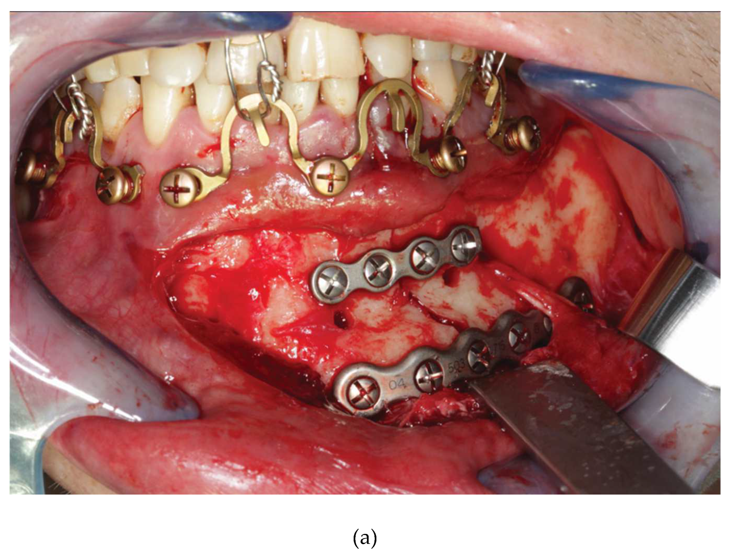
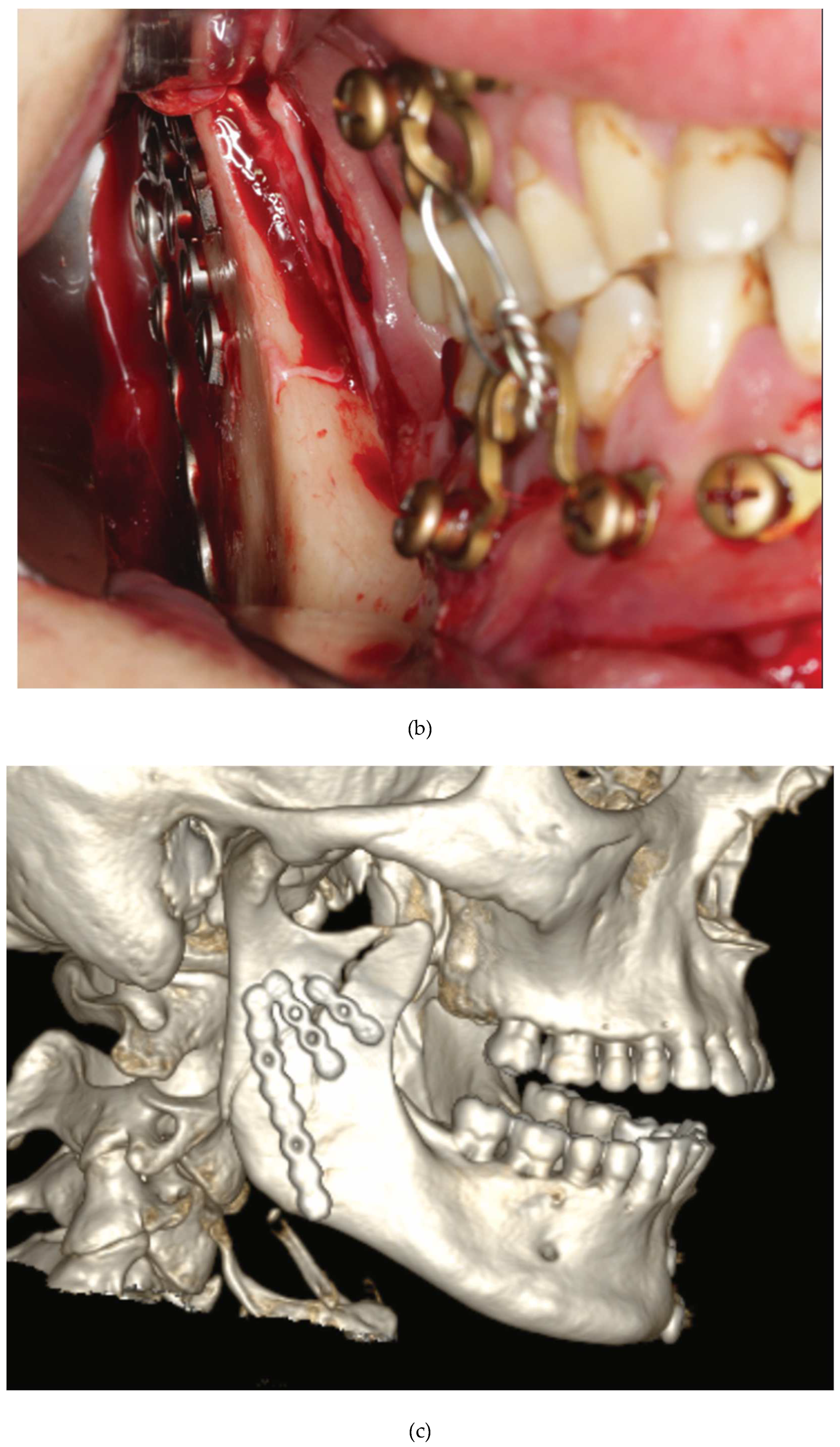
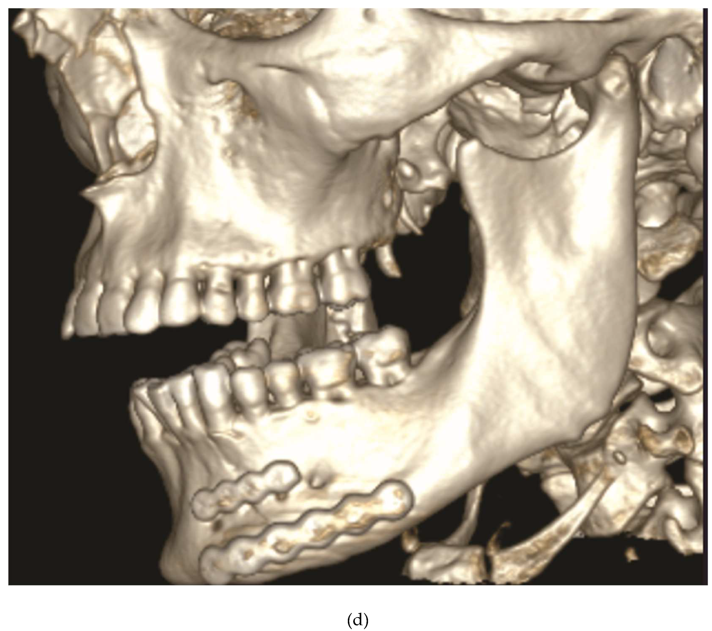
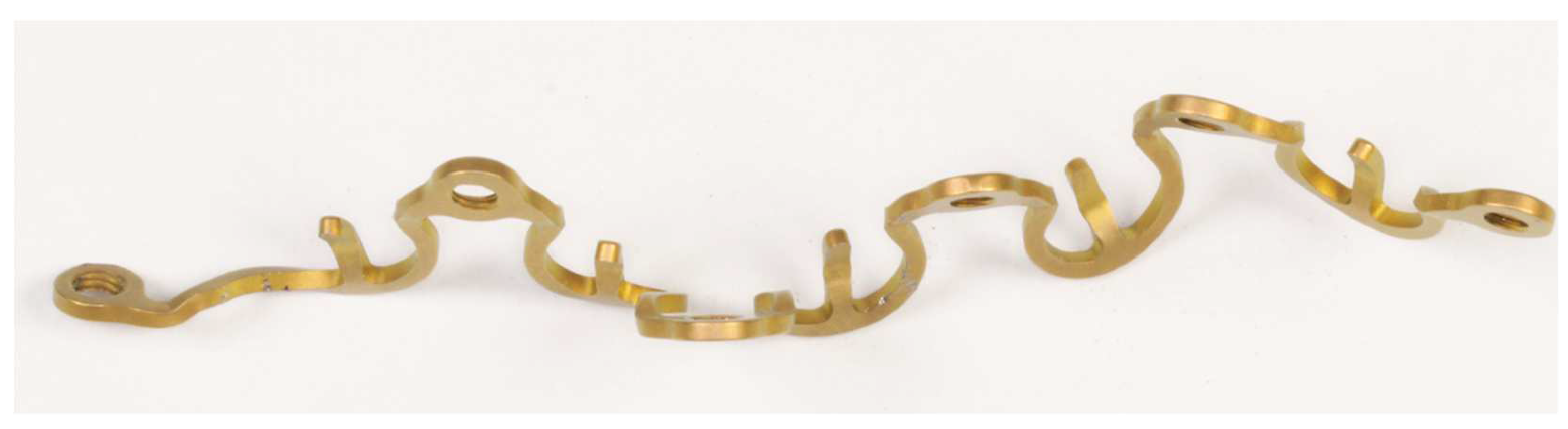
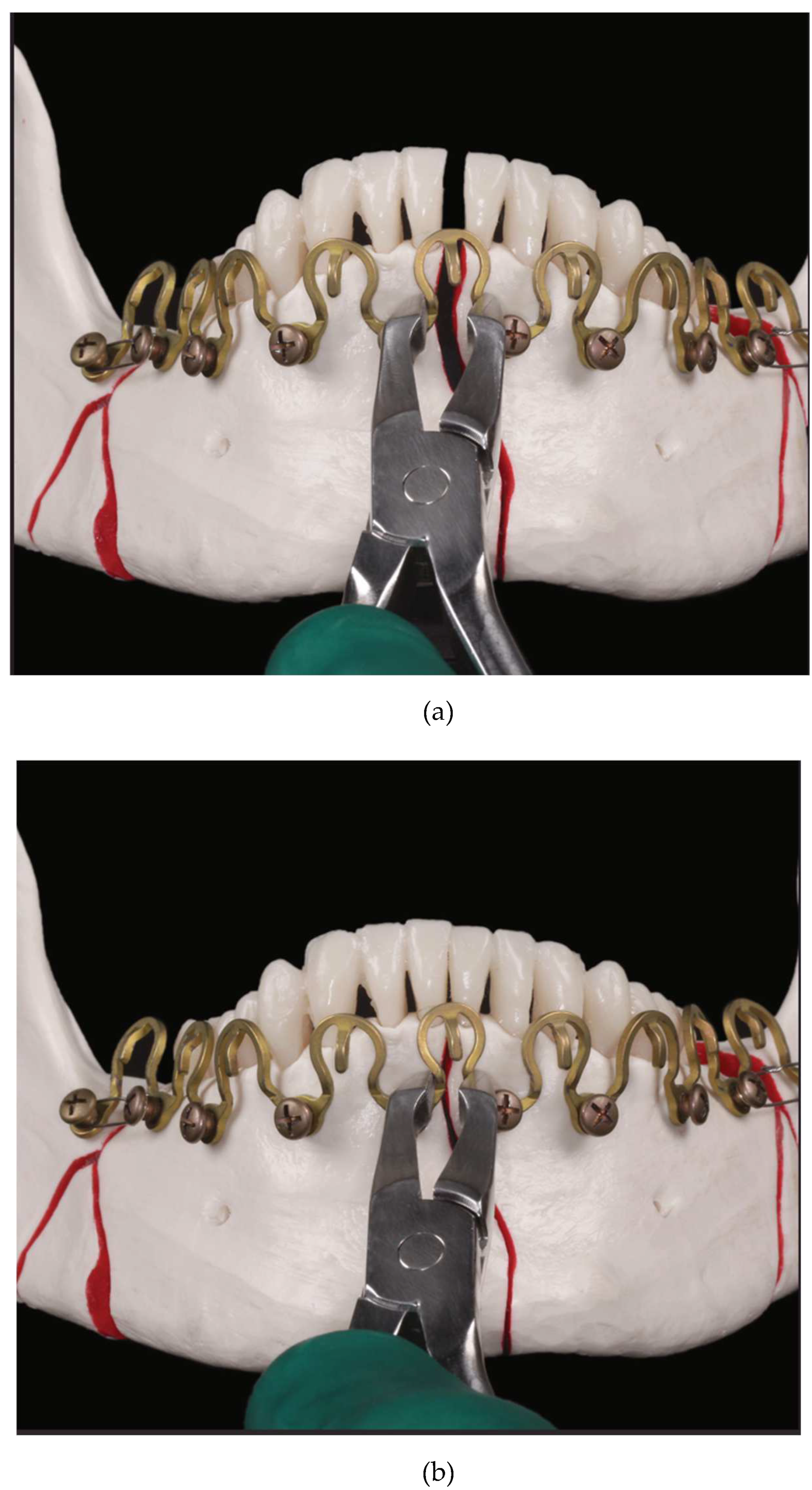
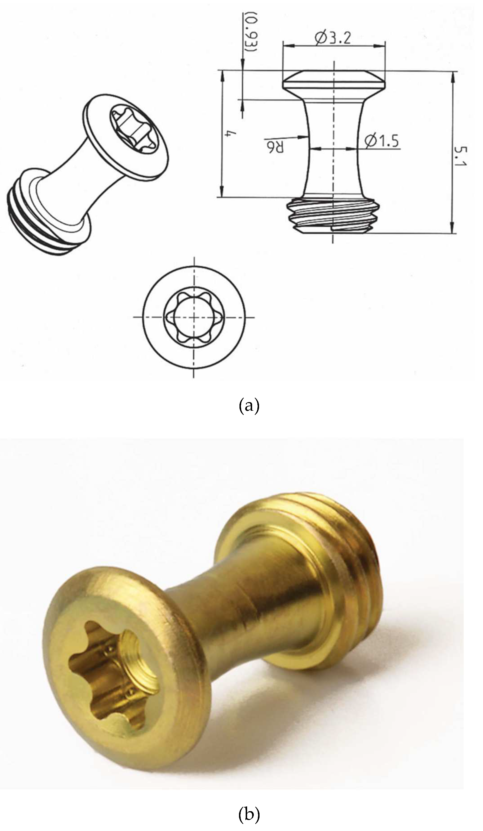
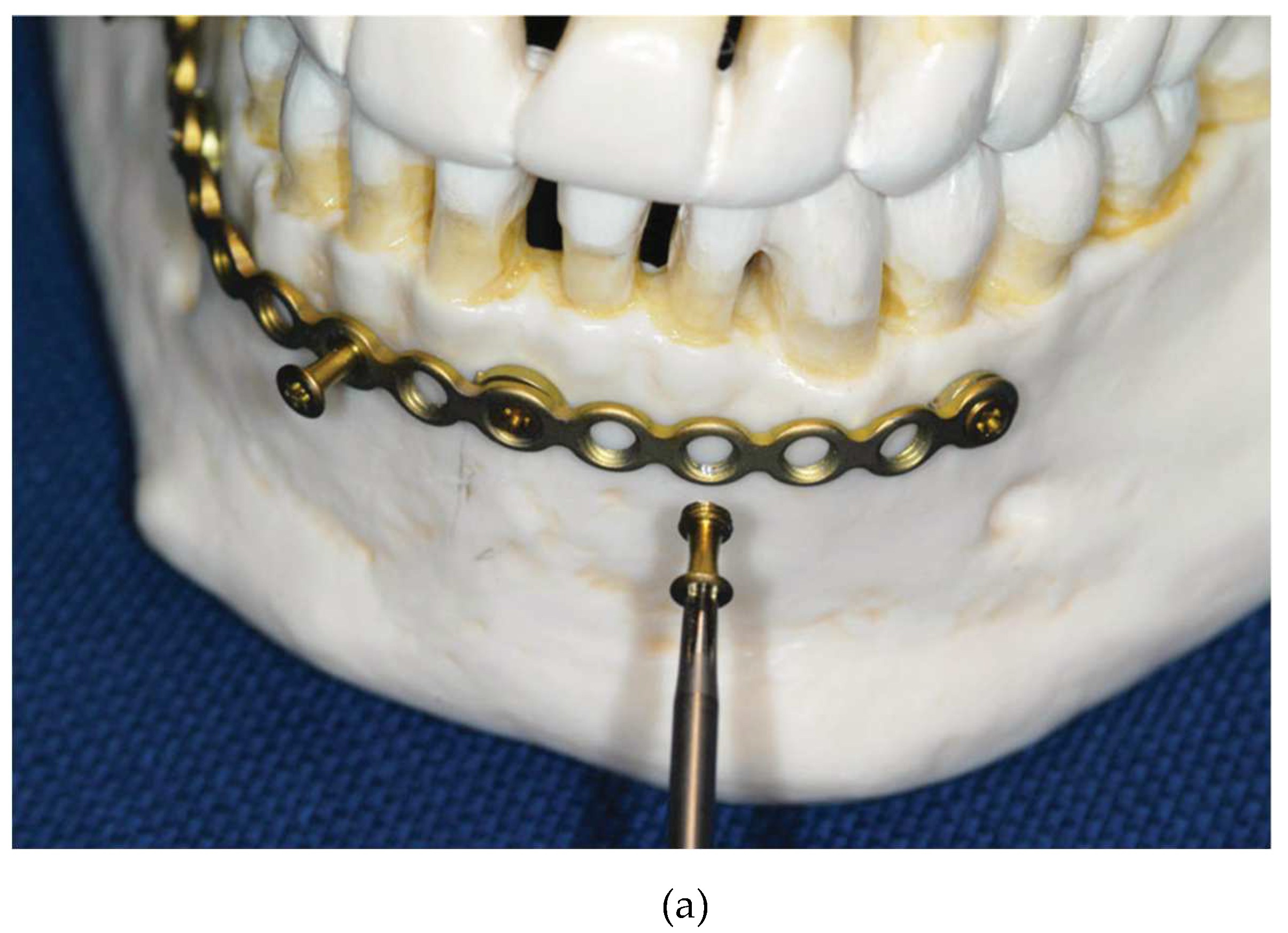
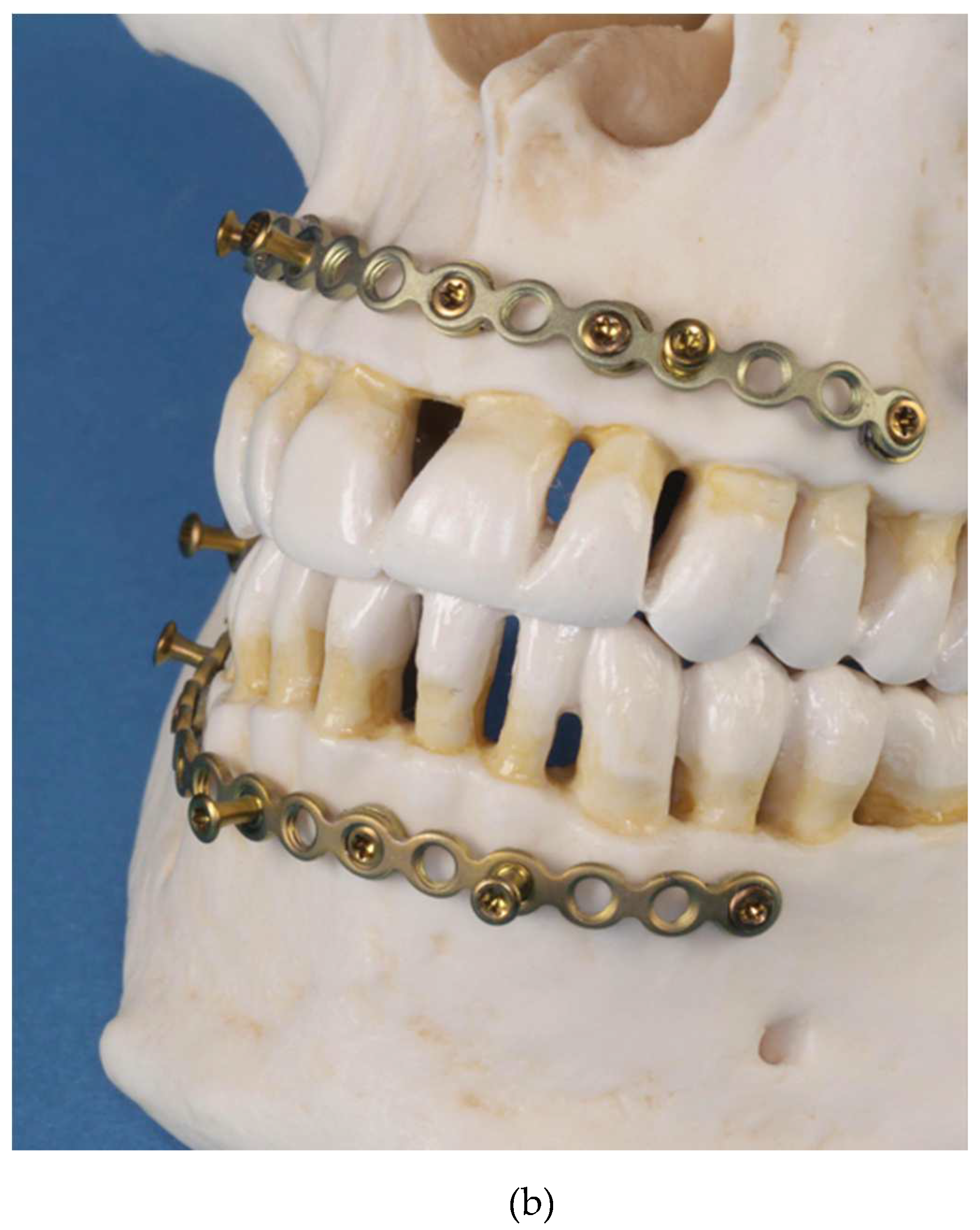
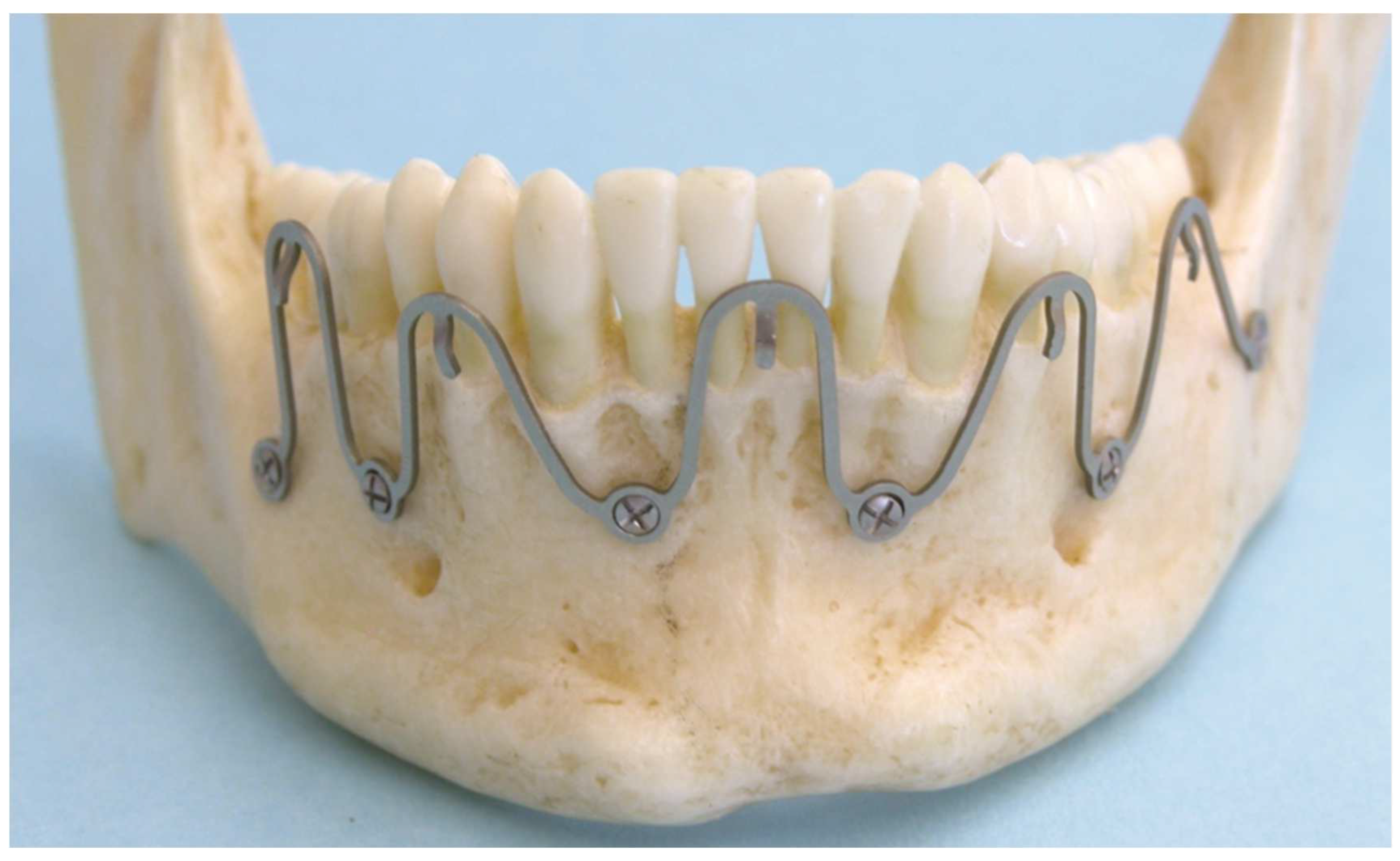
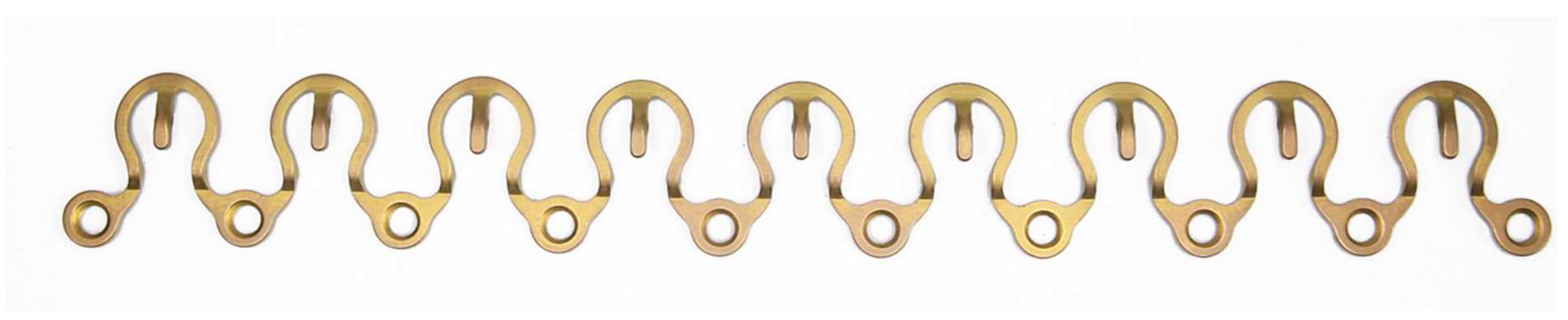
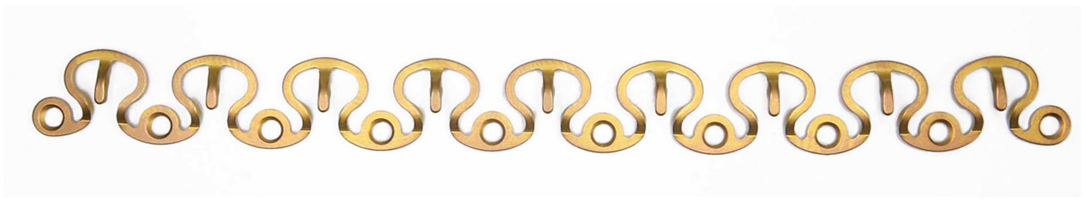
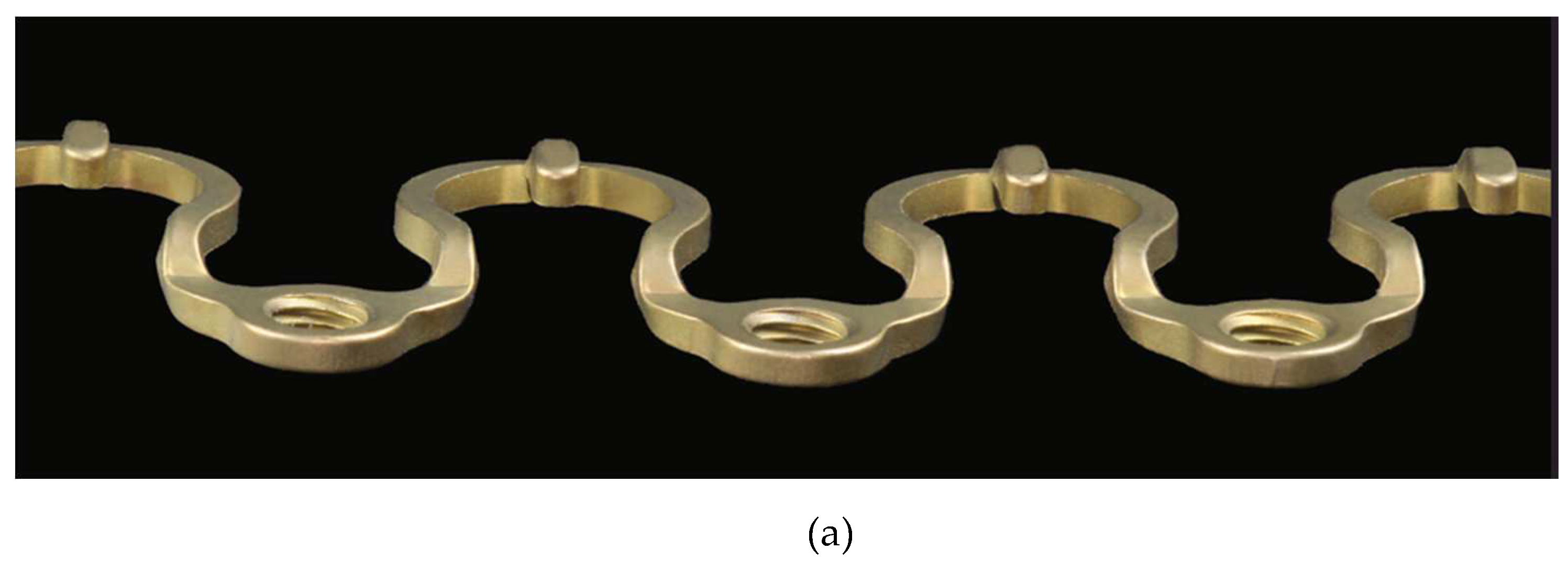
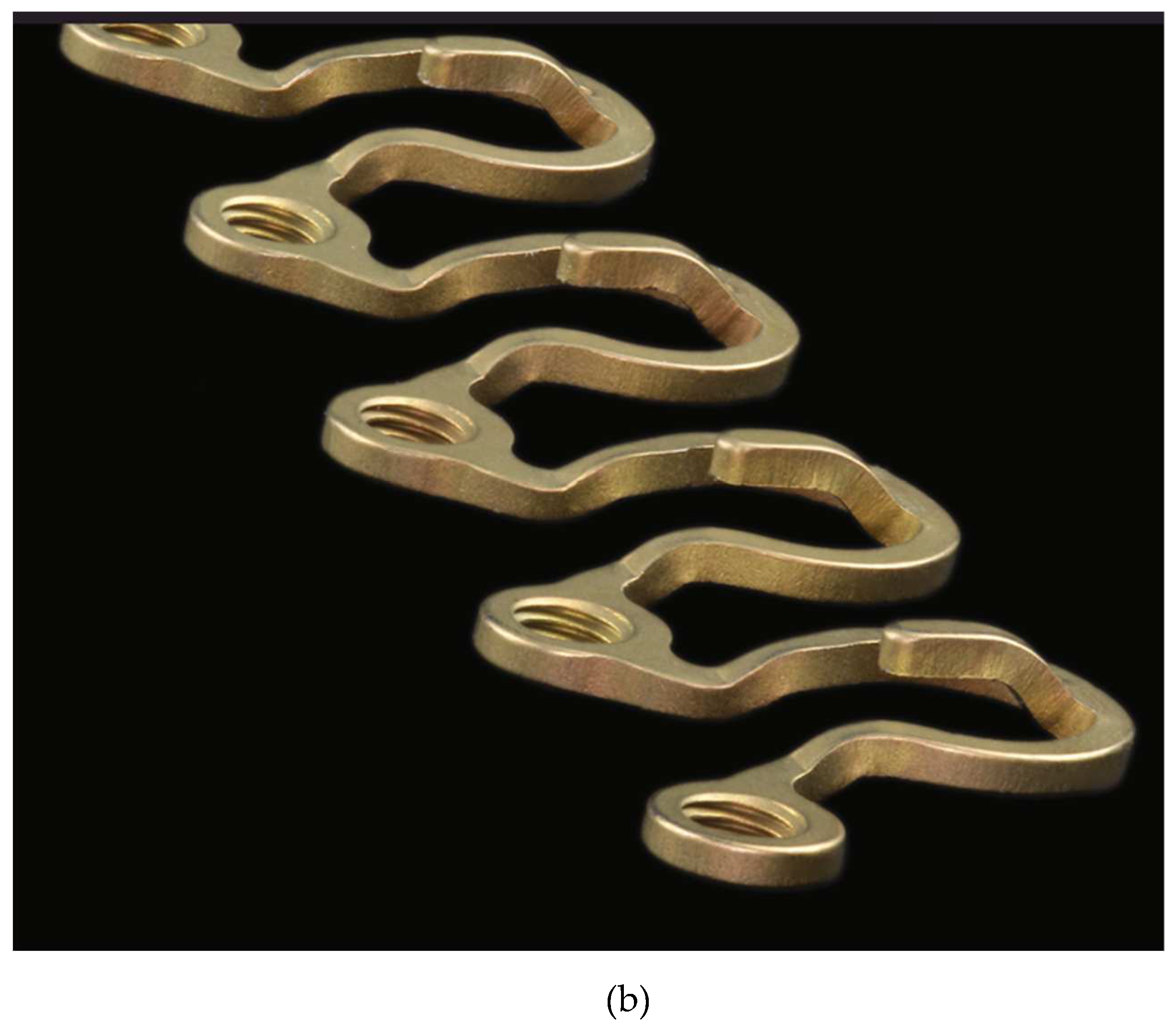
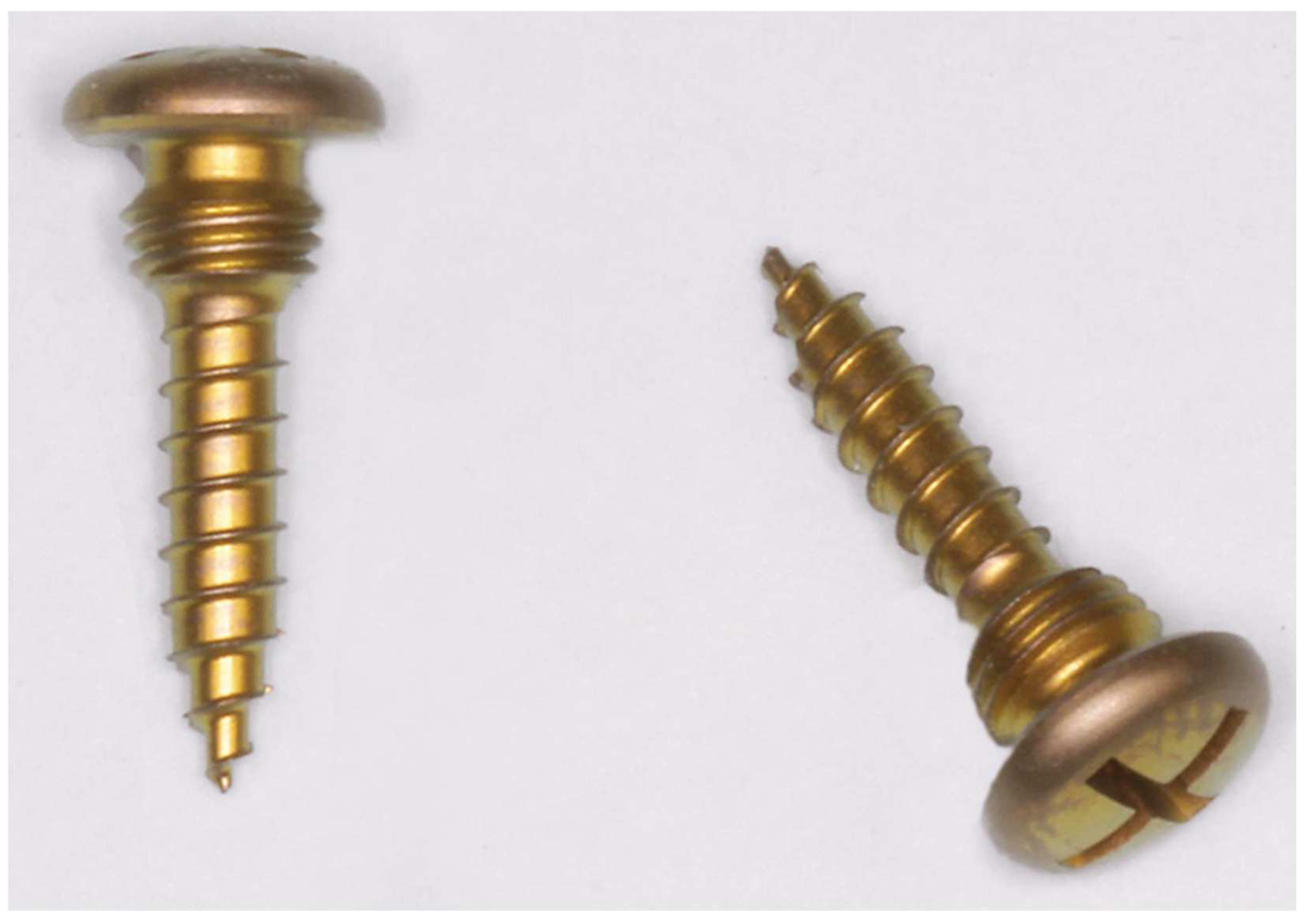
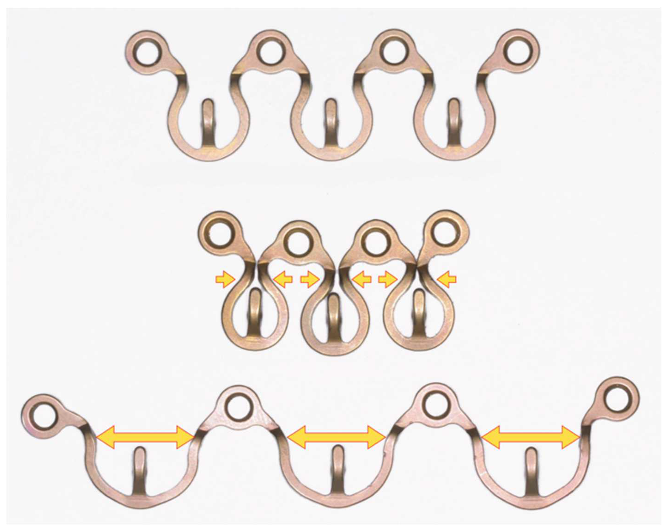
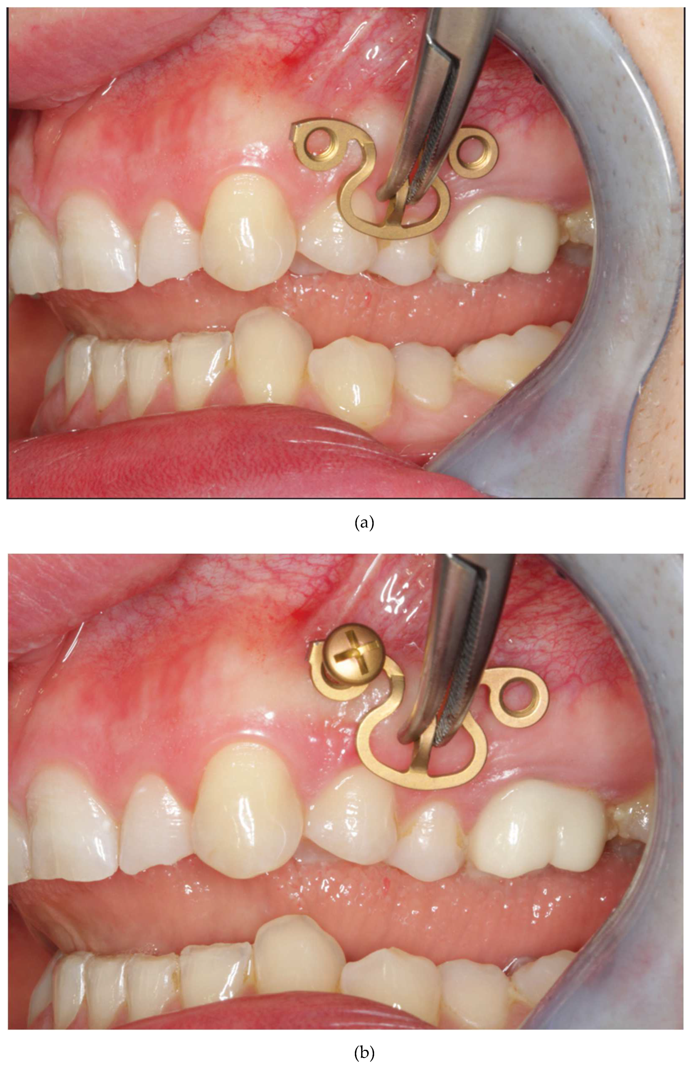
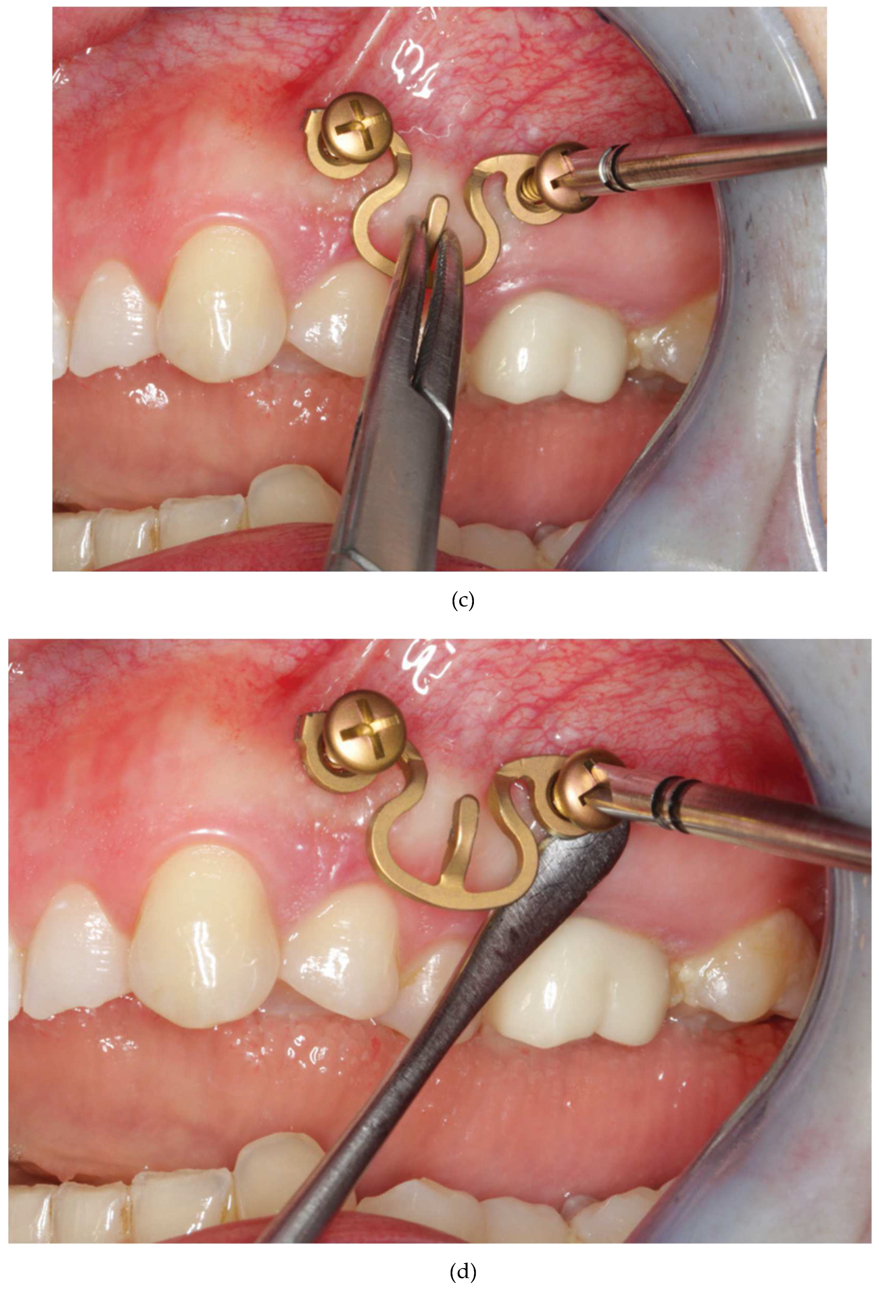
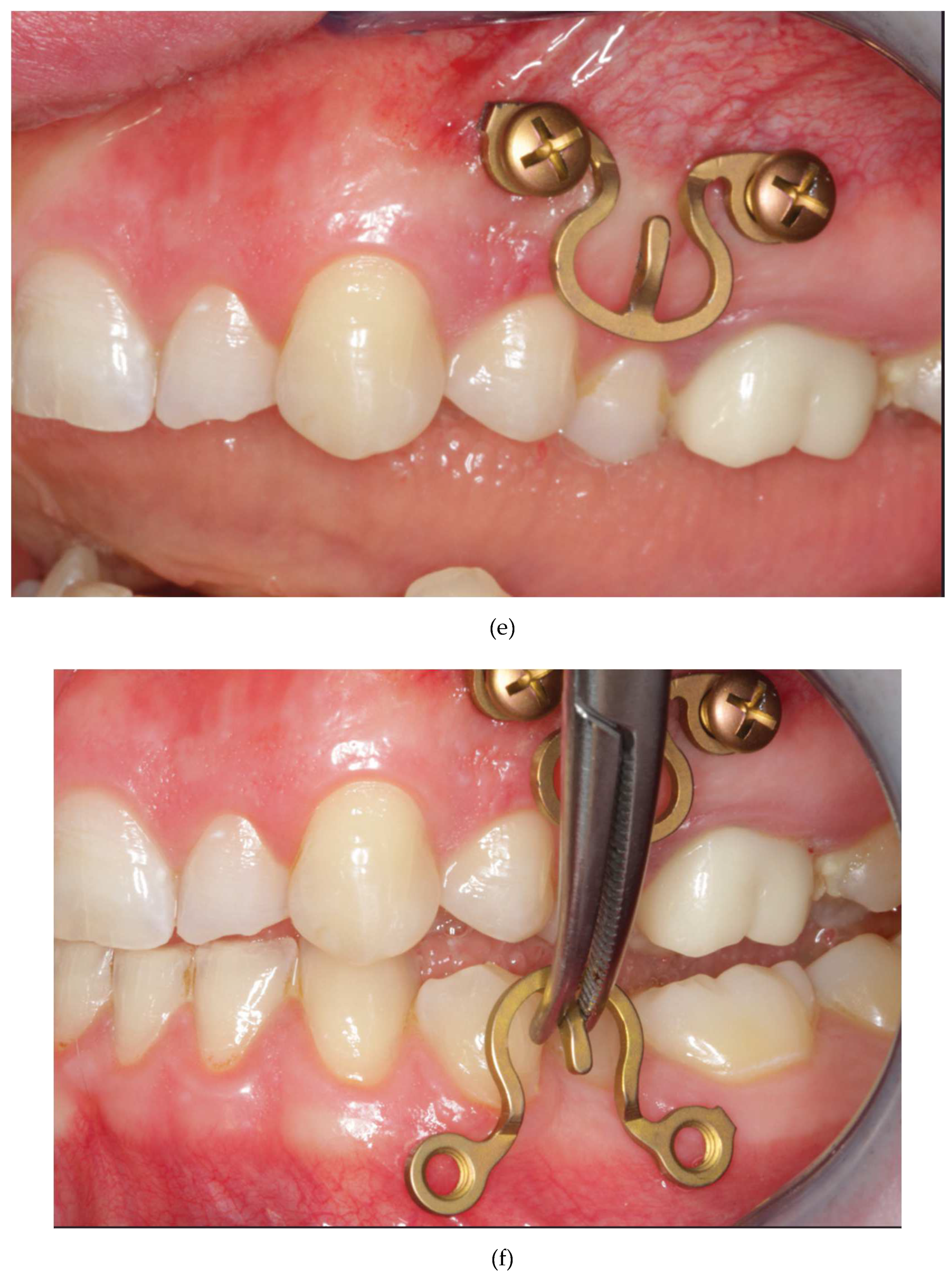
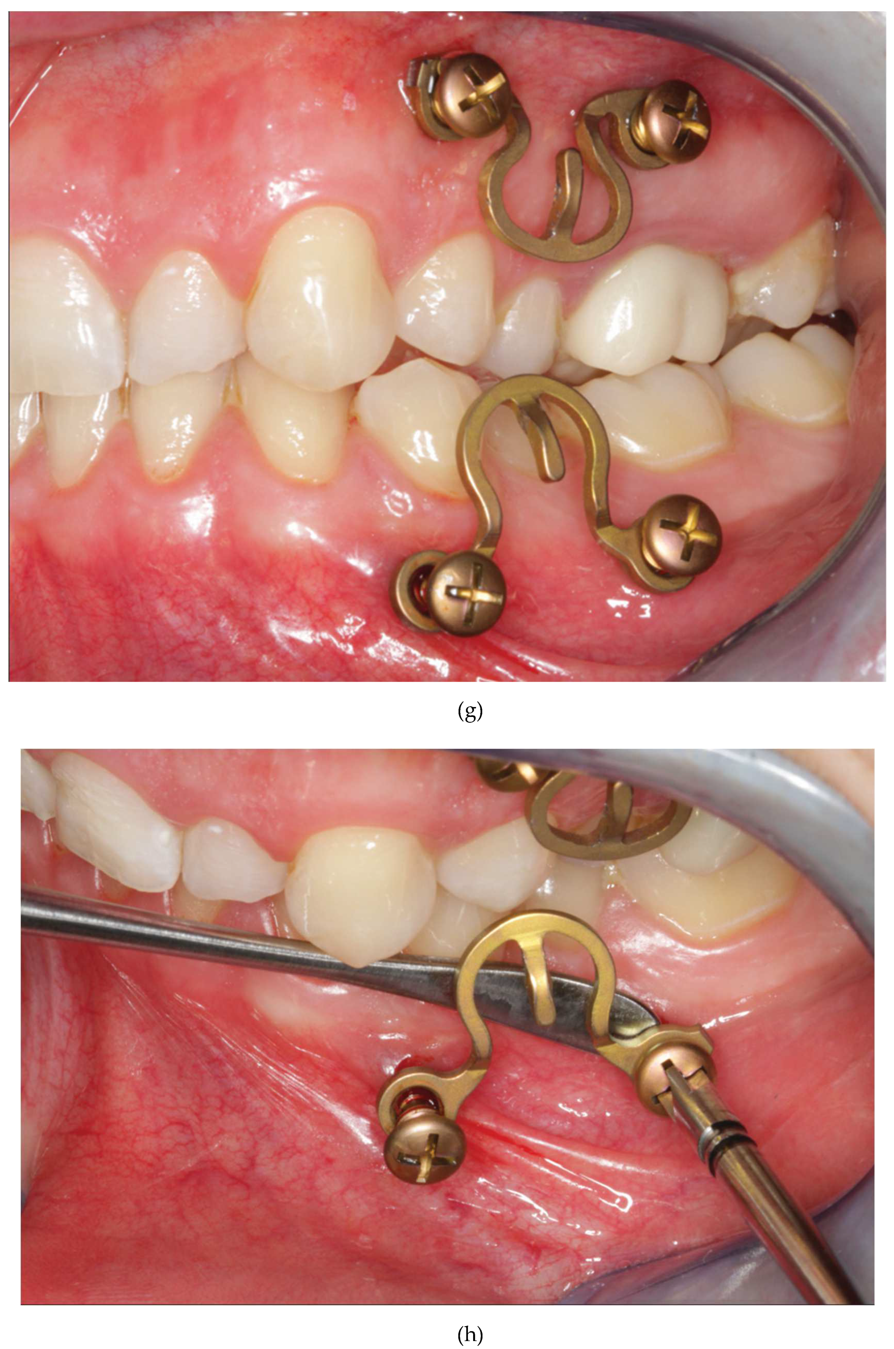
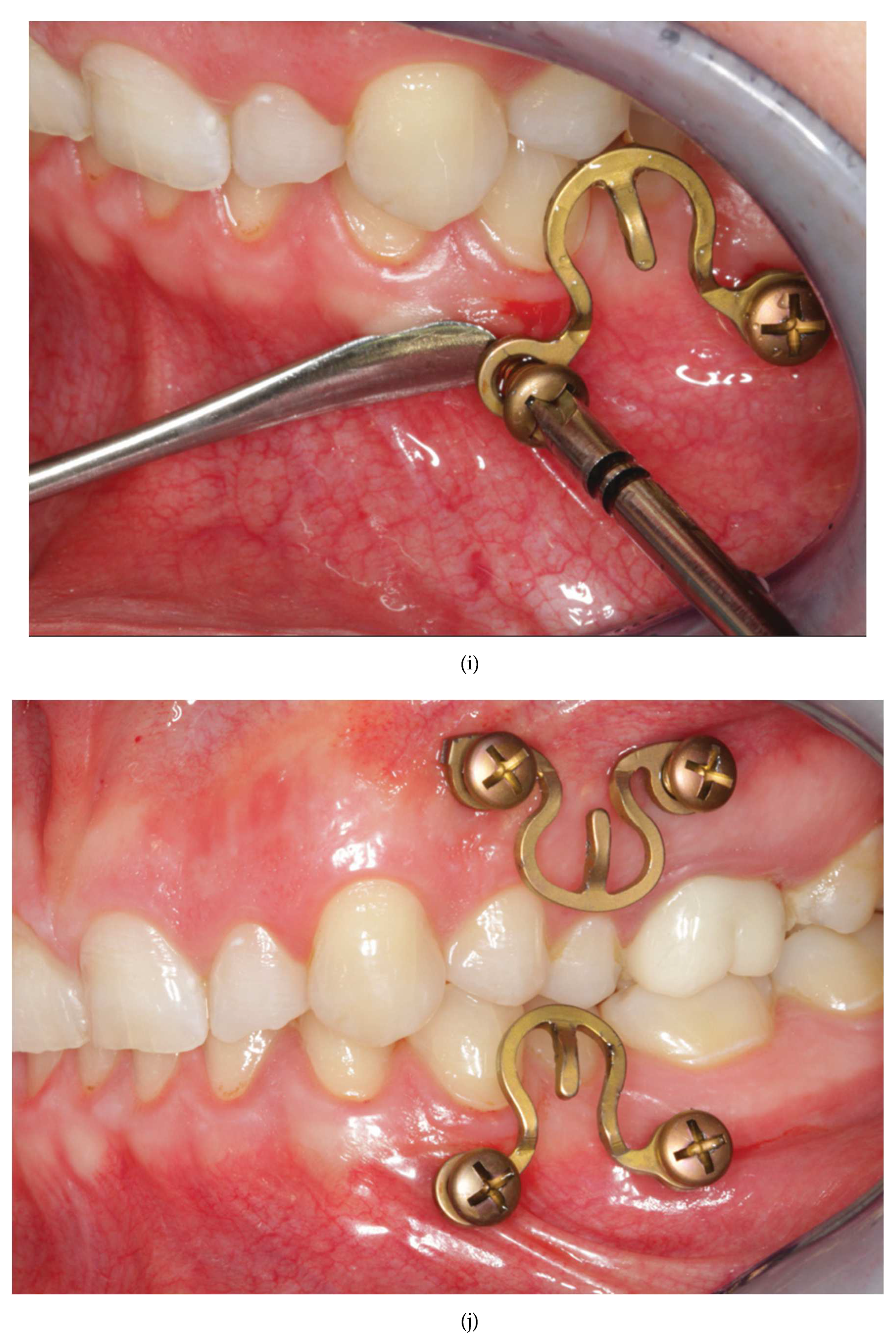
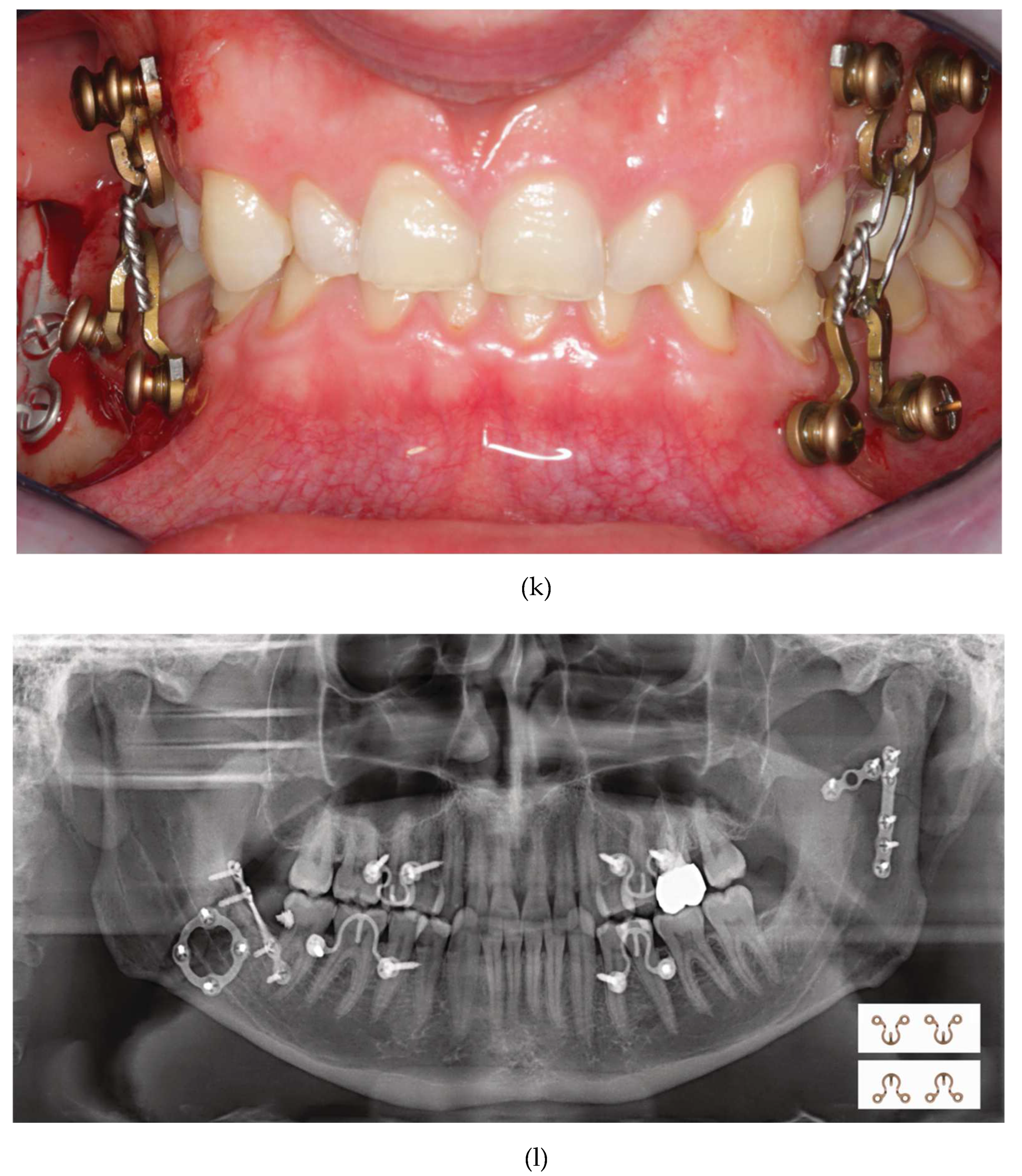
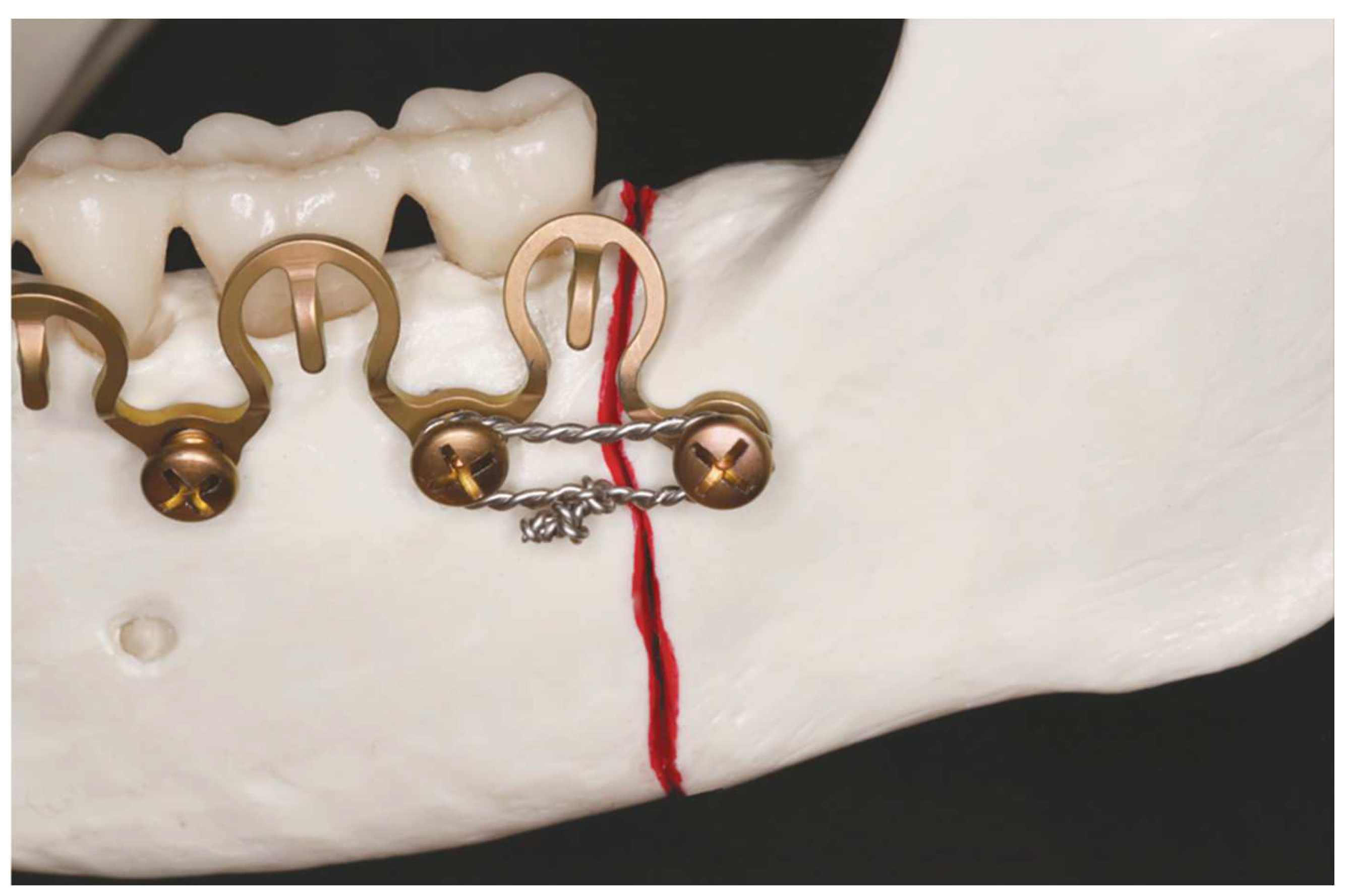
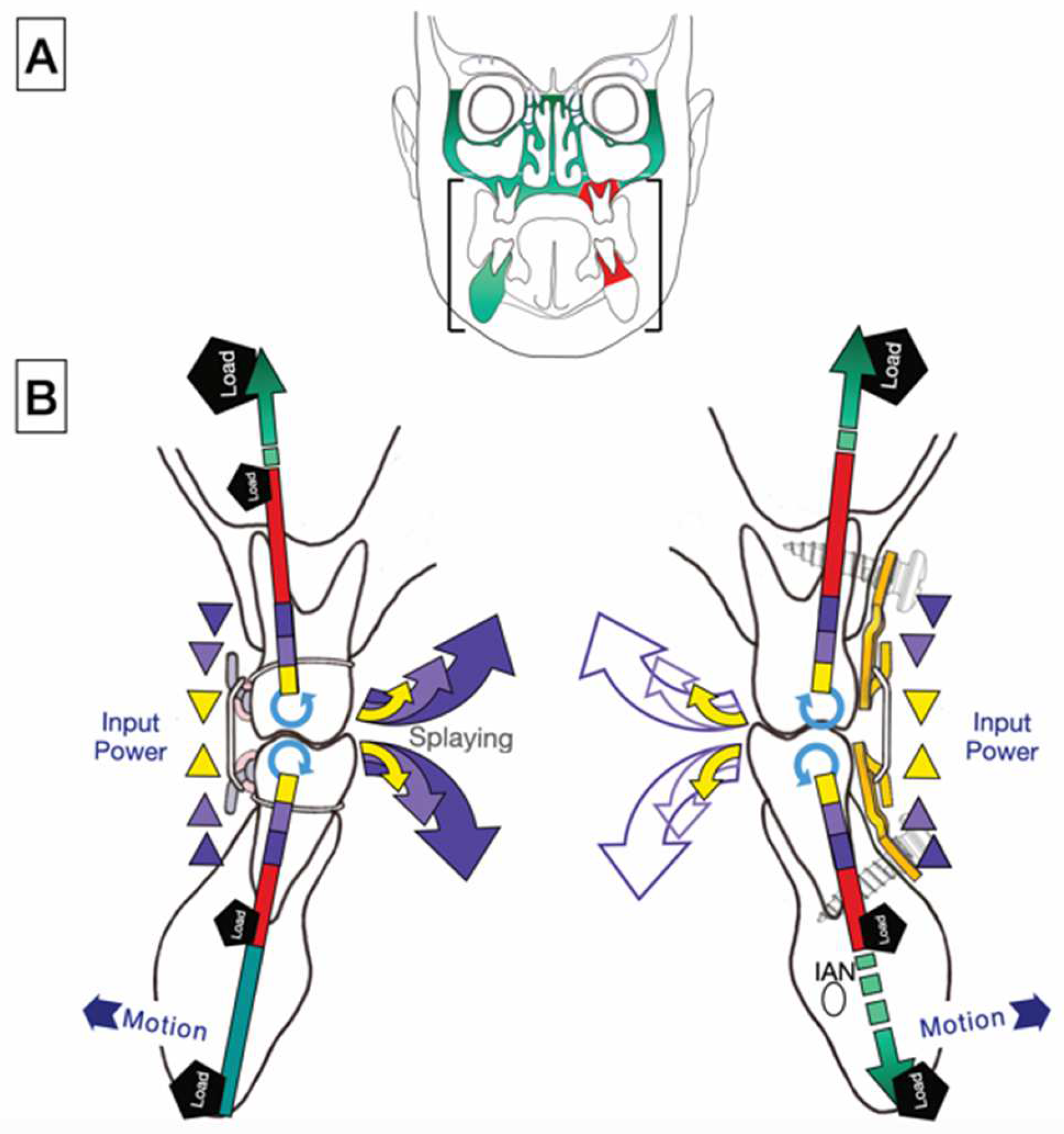
Study design: The advent of Matrix WaveTM System (Depuy-Synthes) - a bone anchored Mandibulo-Maxillary Fixation (MMF) system merits closer consideration because of its peculiarities. Objective: This article alludes to two preliminary stages in the evolution of the Matrix WaveTM MMF System and details its technical and functional features. Results: The Matrix WaveTM System (MWS) is characterized by a smoothed square shaped Titanium rod profile with a flexible undulating geometry unique from the flat plate framework in Erich arch bars. Single MWS segments are Omega-shaped and carry a tie-up-cleat for interarch linkage to the opposite jaw. The ends at the throughs of each MWS segment are equipped with threaded screw holes to receive locking screws for attachment to underlying mandibular or maxillary bone. A MWS can be partitioned into segments of various length from single Omega-shaped elements over incremental chains of interconnected units up to a horseshoe-shaped bracing of the dental arches. The sinus wave design of each segment allows for stretch, compression and torque movements. So the entire MWS device can conform to distinctive spatial anatomic relationships. Displaced fragments can be reduced by in-situ-bending of the screw fixated MWS/Omega segments to obtain accurate realignment of the jaw fragments for the best possible occlusion. Conclusion: The Matrix WaveTM MMF System is an easy to apply modular MMF system, that can be assembled according to individual demands. Its versatility allows to address most facial fracture scenarios in adults. The option of an “omnidirectional” in-situ-bending provides a distinctive feature not found in alternate MMF solutions.
Keywords:
1. Introduction
2. Evolution – Development
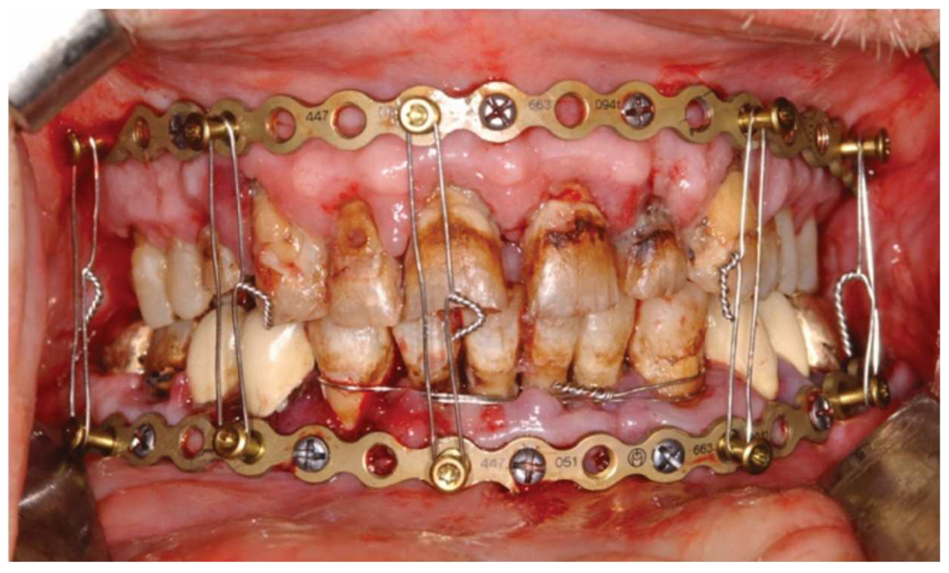
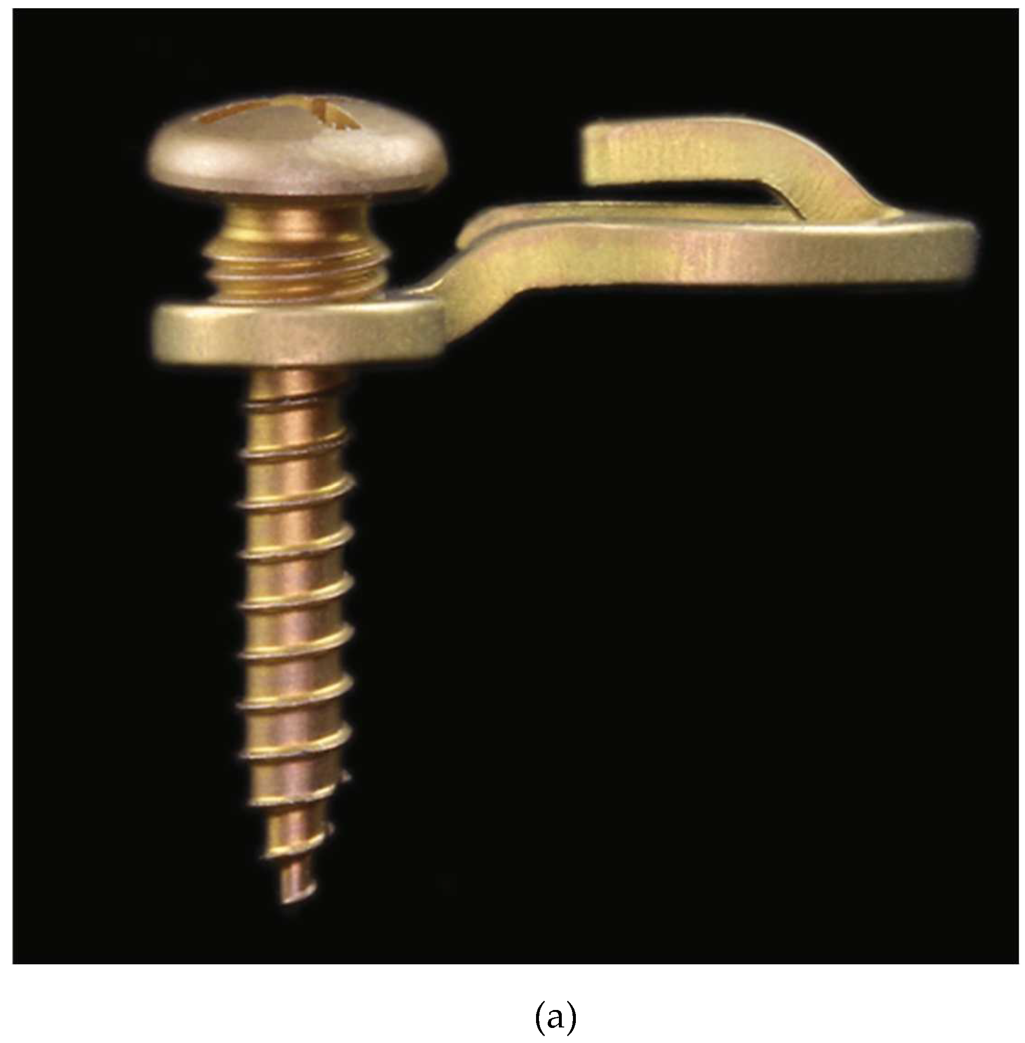
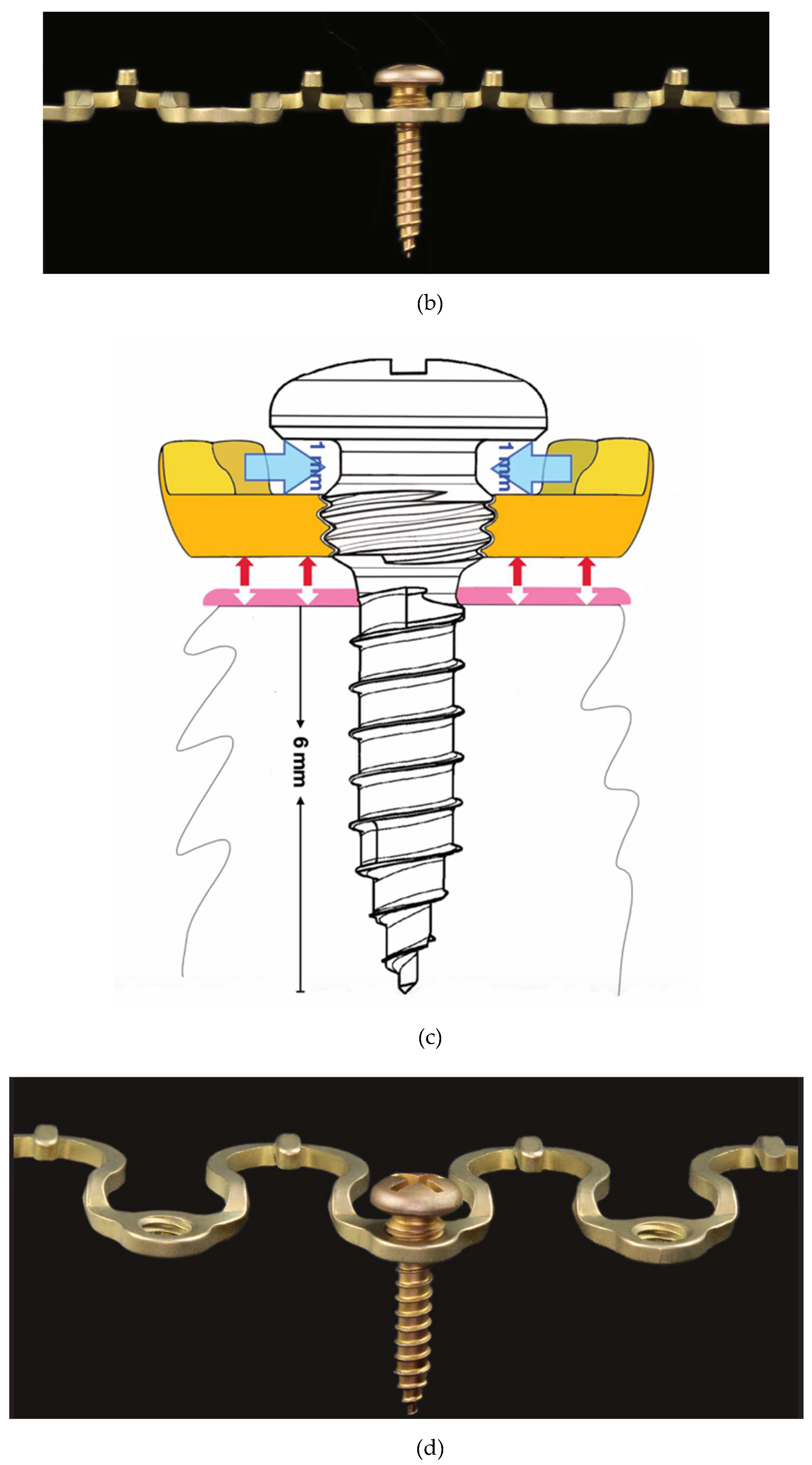
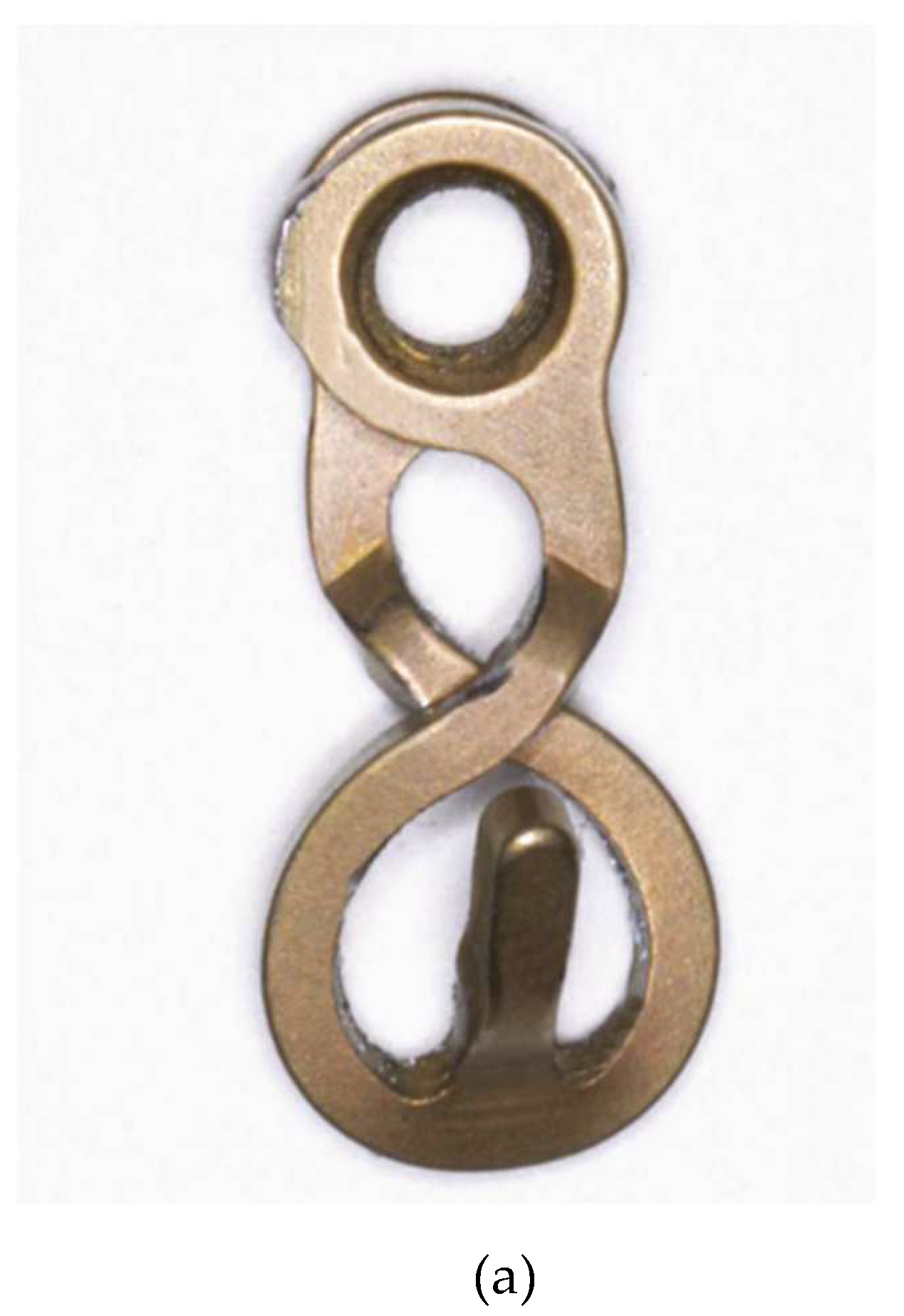
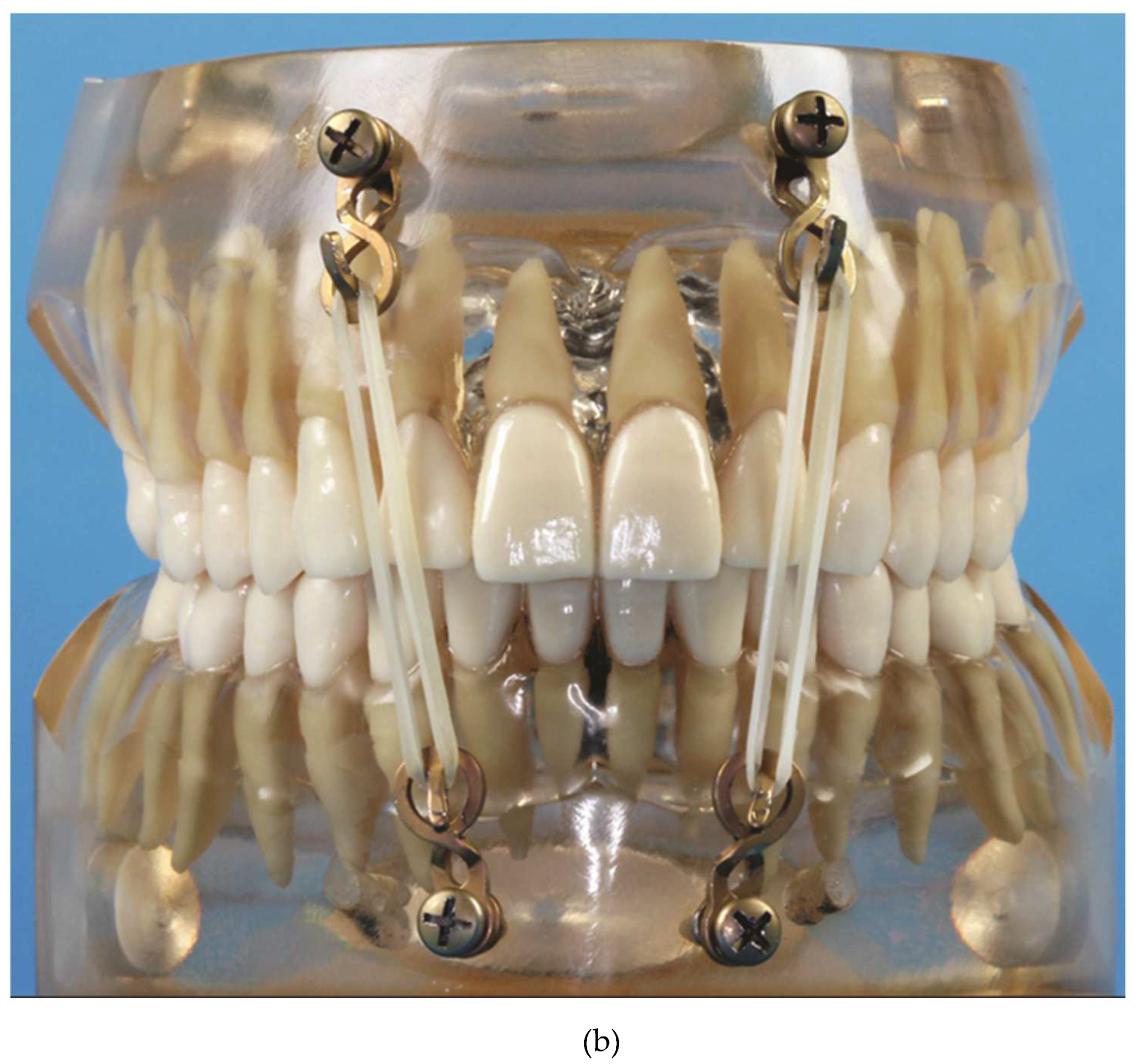
3. Locking Adaption Plate and MMF Nuts[1]
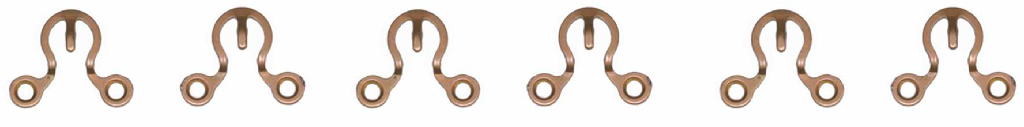
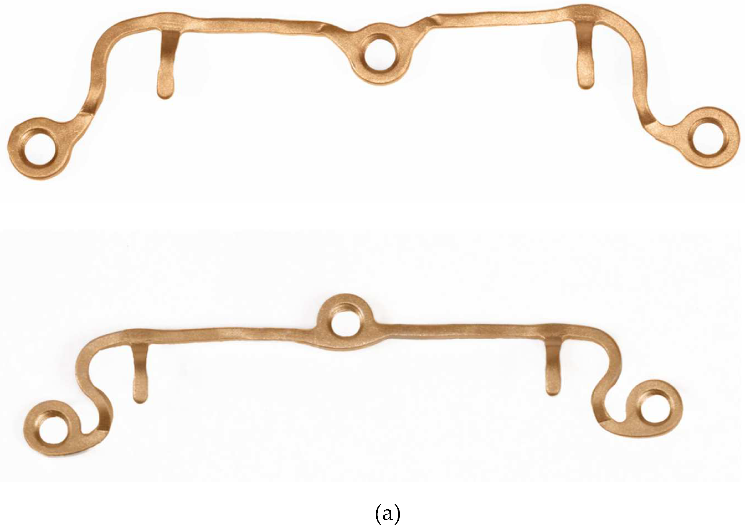
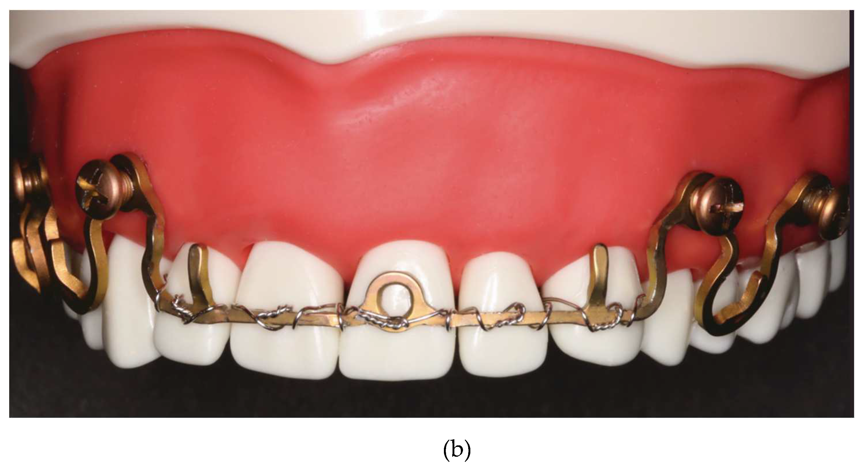
3. Predecessor – 1st Wave Plate2 Version
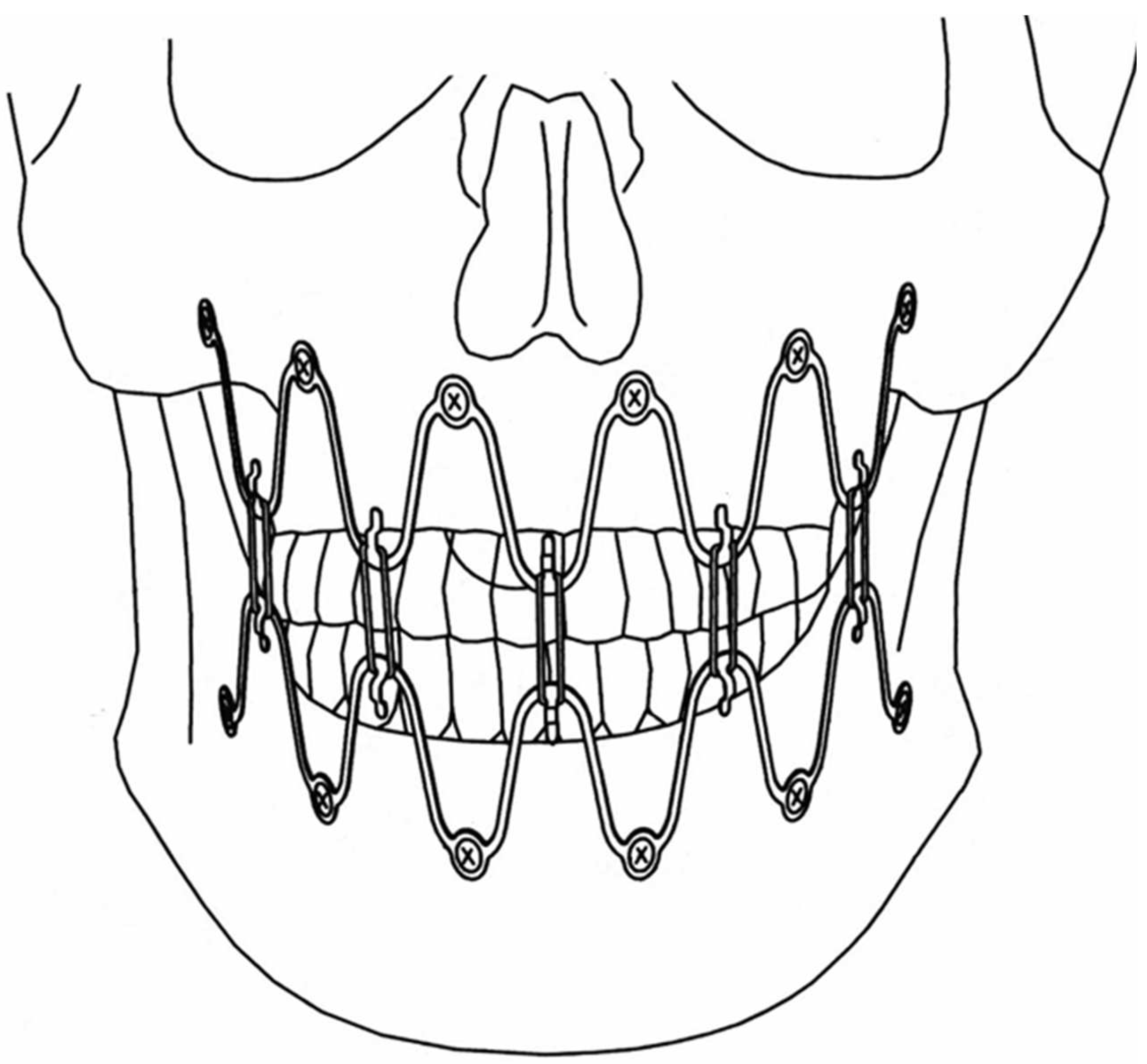
4. Matrix Wave System –Final Design and Technical Description
5. Methods
5.1. Matrix Wave Plate – Segmentation and Malleability
5.2. Matrix WaveTM Plate MMF System - Application Technique
5.3. ‘In situ Bending’ for Fracture Reduction
6. Discussion
6.1. Predecessor – 1st Wave Plate Version
6.2. 2 nd Wave Plate Version: Matrix Wave MMF System
Funding
Acknowledgments
Declaration of Conflicting Interests
References
- Ernst F. Die zahnärztliche Behandlung der Unterkieferfrakturen. In: M Kirschner, ed. Die Chirurgie. Eine zusammenfassende Darstellung der allgemeinen und speziellen Chirurgie. Urban & Schwarzenberg; 1927:842 - 852.
- Ernst F. Die Schienenverbande bei Unter- und Oberkieferbrüchen. In: Bruhn C, Kantorowicz A, Partsch CP, eds. Die Chirurgischen Erkrankungen der Mundhöhle, der Zähne und Kiefer J.F. Bergmann; 1932:115 - 130: Kapitel 16. Abschnitt. Handbuch der Zahnheilkunde.
- Ivy RH. Observations of fracture of mandible.J Am Med Assoc. 1922;79:295.
- Ivy RH, Curtis L. Fractures of the jaws.1st Edition ed. Lea and Febiger; 1931.
- Risdon F. The treatment of fractures of the jaws. Can Med Assoc J. 1929;20 (3):260 - 262.
- Stout RA. Intermaxillary wiring and intermaxillary elastic traction and fixation. In: Navy MDU, ed. Manual of standard practice of plastic and maxillofacial surgery. W.B.Saunders Co.; 1943:272. Military Surgical Manuals National Research Council.
- Obwegeser H. Über eine einfache Methode der freihändigen Drahtschienung von Kieferbrüchen. Österreichische Z Stomatol. 1952; 49:652.
- Otten JE. Modifizierte Methode zur intermaxillären Fixation [Modified methods for intermaxillary immobilization]. Dtsch Zahnaerztl Z 1981;36 (2):91–92.
- Arthur G, Berardo N. A simplified technique of maxillomandibular fixation. J Oral Maxillofac Surg. Nov 1989;47(11):1234. [CrossRef]
- Rinehart GC. Mandibulomaxillary fixation with bone anchors and quick-release ligatures. J Craniofac Surg. May 1998;9(3):215-21. [CrossRef]
- Gilmer TL. A case of fracture of lower jaw with remarks on treatment. Arch Dent. 1887; 4:388.
- Sauer C. Herstellung eines neuen Verbandes bei Unterkieferbrüchen. Dtsch Vjschr Zahnheilk. 1881;21:362 - 375.
- Sauer C. Notverband bei Kieferbrüchen mit Eisendraht. Dtsch Mschr Zahnheilk. 1889;7:381-392.
- Hauptmeyer F. Die Behandlung der Brüche des Unter- und Oberkiefers mittels Zahnschienen.. In: Partsch C, Bruhn C, Kantorowicz A, eds. Handbuch der Zahnheilkunde. BergmannJ.F.; 1917:104 -145.
- United States Patent, Patent No.: US 1638006 – 9 August, 1927. Inventors, Aderer H, Jelenko JF. Fracture splint. Assignee: J.F. Jelenko and Co., New York, NY.
- Erich JB. Treatment of fractures of the upper jaw. J Am Dental Assoc - JADA. 1942;29(5):783-793. [CrossRef]
- Erich JB, Austin LT, Medicine USNDBo, Surgery. Traumatic Injuries of Facial Bones: An Atlas of Treatment. Saunders; 1944.
- Schuchardt K. Ein Vorschlag zur Verbesserung der Drahtschienenverbände. Dtsch Zahn Mund Kieferheilk. 1956;24:39-44.
- Schuchardt K, Kapovits M, Spiessl B. Technik und Anwendung des Drahtbogenkunsstoffverbandes. Dtsch Zahnarztl Z. 1961;16:1241-1249.
- Stanhope E. Acrylated arch bars. The BritishJounal of Oral Surgery. 1969;7 (2):81-83.
- Iizuka T, Hallermann W, Seto I, Smolka W. A titanium arch bar for maxillomandibular fixation in oral and maxillofacial surgery. J Oral Maxillofac Surg. Jun 2006;64(6):989-992. [CrossRef]
- Baurmash HD. Bonding as an overdue replacement of the wiring of arch bars - Letter to the editor. J Oral Maxillofac Surg. Nov 2006;64(11):1701-2. [CrossRef]
- McCaul JA, Devlin MF, Lowe T. A new method for temporary maxillo-mandibular fixation. Int J Oral Maxillofac Surg. Jul 2004;33(5):502-3. [CrossRef]
- Pigadas N, Whitley SP, Roberts SA, McAlister K, Ameerally P, Avery CM. A randomized controlled trial on cross-infection control in maxillofacial trauma surgery: a comparison of intermaxillary fixation techniques. Int J Oral Maxillofac Surg. Aug 2008;37(8):716-22. [CrossRef]
- Cousin GC. Wire-free fixation of jaw fractures. Br J Oral Maxillofac Surg. Oct 2009;47(7):521-4. [CrossRef]
- Johnson AW. Dental occlusion ties: A rapid, safe, and non-invasive maxillo-mandibular fixation technology. Laryngoscope Investig Otolaryngol. Aug 2017;2(4):178-183. [CrossRef]
- Jenzer AC, Malz C, Fillmore J, et al. The Role of Dental Occlusion Ties to Achieve Stable Maxillomandibular Fixation During Temporomandibular Joint Replacement. J Oral Maxillofac Surg. Nov 2022;80(11):1731-1739. [CrossRef]
- Druelle C, Touzet-Roumazeille S, Raoul G, Ferri J, Nicot R. How to produce pre-shaped rigid arch bars using low-cost 3D printing technology - A technical note. J Stomatol Oral Maxillofac Surg. Sep 2017;118(4):213-216. [CrossRef]
- Tache A, Huys SEF, Mommaerts MY. CADCAM Arch Bars: A technical note. Craniomaxillofacial Trauma & Reconstruction Open. 2021;6:1-5. [CrossRef]
- de Queiroz SB. Modification of arch bars used for intermaxillary fixation in oral and maxillofacial surgery. Int J Oral Maxillofac Surg. Apr 2013;42(4):481-482. [CrossRef]
- Suresh V, Sathyanarayanan N, Venugopalan V, Beena AT. A simple maneuvre for promising results - opening the winglets of an arch bar for placement of screws: a Technical note. GJRA - Global Journal for Research Analysis. 2015;4(5): 368-369.
- Hassan S, Farooq S, Kapoor M, Shah A. Comparative evaluation of modified Erich’s arch bar, conventional Erich’s arch bar and intermaxillary fixation screws in maxillo-mandibular fixation: a prospective clinical study. Int J Med Res Prof. 2018;4(4):41 - 45. [CrossRef]
- Rothe TM, Kumar P, Shah N, Shah R, Kumar A, Das D. Evaluation of efficacy of intermaxillary fixation screws versus modified arch bar for intermaxillary fixation. Natl J Maxillofac Surg. Jul-Dec 2018;9(2):134-139. [CrossRef]
- Rothe TM, Kumar P, Shah N, Shah R, Mahajan A, Kumar A. Comparative evaluation of efficacy of conventional arch bar, intermaxillary fixation screws, and modified arch bar for intermaxillary fixation. J Maxillofac Oral Surg. Sep 2019;18(3):412-418. [CrossRef]
- Pathak P, Thomas S, Bhargava D, Beena S. A prospective comparative clinical study on modified screw retained arch bar (SRAB) and conventional Erich’s arch bar (CEAB). Oral Maxillofac Surg. Sep 2019;23(3):285-289. [CrossRef]
- Venugopalan V, Satheesh G, Balatandayoudham A, Duraimurugan S, Balaji TS. A comparative randomized prospective clinical study on modified Erich arch bar with conventional Erich arch bar for maxillomandibular fixation. Ann Maxillofac Surg. Jul-Dec 2020;10(2):287-291. [CrossRef]
- United States Patent, Patent No.: US 10,470,806 B2 – 12 November 2019, Inventors: Kohler K, Pinto J, Johnston TS, Jr., Papay FA. Maxillomandibular Fixation Devices. Assignee: KLS Martin, L.P. Jacksonville, FL (USA); The Cleveland Clinic Foundation, Cleveland, OH (USA); 11/2019.
- United States Patent, Patent No.: US 2011,0152946 A1 – 23 June, 2011, Inventors: Frigg R, Richter J, Leuenberger S, Cornelius CP, Hamel RJ. Flexible Maxillo Mandibular Fixation Device. Assignee: DePuy Synthes Products, Inc.,Rayham, MA (USA); 2018.
- United States Patent, Patent No.: US 9,820,77 B2 – 23 June 2018; Inventors: Woodburn WN, Griffith W, Barber JR, Parranto G. Flexible Maxillo- Mandibular Fixation Device. Assignee: DePuy Synthes Products Inc., Rayham, MA (USA); 2018.
- Cornelius CP, Hardeman J. Craniomaxillofacial – Matrix Wave MMF. AOTK System Innovations. 2015:19 - 21.
- Kiwanuka E, Iyengar R, Jehle CC, Mehrzad R, Kwan D. The use of Synthes MatrixWAVE bone anchored arch bars for closed treatment of multiple concurrent mandibular fractures. J Oral Biol Craniofac Res. Sep-Dec 2017;7(3):153-157. [CrossRef]
- Ellis E, 3rd, Tharanon W. Facial width problems associated with rigid fixation of mandibular fractures: case reports. J Oral Maxillofac Surg. Jan 1992;50(1):87-94. [CrossRef]
- Chen S, Zhang Y, An JG, He Y. Width-controlling fixation of symphyseal/parasymphyseal fractures associated with bilateral condylar fractures with 2 2.0-mm miniplates: a retrospective investigation of 45 cases. J Oral Maxillofac Surg. Feb 2016;74(2):315-327. [CrossRef]
- Gerbino G, Boffano P, Bosco GF. Symphyseal mandibular fractures associated with bicondylar fractures: a retrospective analysis. J Oral Maxillofac Surg. Aug 2009;67(8):1656-1660. [CrossRef]
- Spiessl B. Application of the tension band principle in the Mandible, Tension band plate Part I, Basic principles, 4.1.2.1 - 4.1.2.4 , pp 34. Internal Fixation of the Mandible – A Manual of AO/ASIF Principles, Springer-Verlag; 1989.
- Wang RC, Keech DR, Elkins TP, Russell P. The tension wire method: a simple, effective means of mandibular fixation. Arch Otolaryngol Head Neck Surg. Apr 1998;124(4):448-452. [CrossRef]
- Hasegawa A, Leake D. A new arch bar for oral surgery. Int J Oral Surg. Dec 1981;10(6):462-464. [CrossRef]
- Kornman KS, Holt SC, Robertson PB. The microbiology of ligature-induced periodontitis in the cynomolgus monkey. J Periodontal Res. Jul 1981;16(4):363-371. [CrossRef]
- Tatakis DN, Kumar PS. Etiology and pathogenesis of periodontal diseases. Dental Clinics of North America. 2005;49(3):491-516. [CrossRef]
- Pedemonte C, Valenzuela K, González LE, Vargas I, Noguera A. Types of intermaxillary fixation and their interaction with palatine fracture reduction. J Oral Maxillofac Surg. Oct 2019;77(10):2083.e1-2083.e8. [CrossRef]
- Gray J. The mechanism of locomotion in snakes. J Exp Biol. Dec 1946;23(2):101-120. [CrossRef]
- Jayne BC. What Defines Different Modes of Snake Locomotion? Integr Comp Biol. Jul 1 2020;60(1):156-170. [CrossRef]
- Park KN, Oh SM, Lee CY, Kim JY, Yang BE. Design and application of hybrid maxillomandibular fixation for facial bone fractures. J Craniofac Surg. 2013;24(5):1801-1805. [CrossRef]
- Falci SG, Douglas-de-Oliveira DW, Stella PE, Santos CR. Is the Erich arch barthe best intermaxillary fixation method in maxillofacial fractures? A systematic review. Med Oral Patol Oral Cir Bucal. Jul 1 2015;20(4):e494-499. [CrossRef]
- Schneider AM, David LR, DeFranzo AJ, Marks MW, Molnar JA, Argenta LC. Use of specialized bone screws for intermaxillary fixation. Ann Plast Surg. Feb 2000;44(2):154-157.
- Ho KS, Tan WK, Loh HS. Case reports: the use of intermaxillary screws to achieve intermaxillary fixation in the treatment of mandibular fractures. Ann Acad Med Singapore. Jul 2000;29(4):534-537.
- Maurer P, Syska E, Eckert AW, Berginski M, Schubert J. Die FAMI-Schraube fur die temporare intermaxillare Fixation. Erfahrungsbericht zur Indikationserweiterung [The FAMI screw for temporary intermaxillary fixation. Report of experiences for extending indications]. Mund Kiefer Gesichtschir. Sep 2002;6(5):360-362.
- Hoffmann A, Mast G, Ehrenfeld M. Verwendung von IMF-Schrauben zur mandibulo-maxillären Fixation. OP-Journal. 2003;19:70-75.
- Fabbroni G, Aabed S, Mizen K, Starr DG. Transalveolar screws and the incidence of dental damage: a prospective study. Int J Oral Maxillofac Surg. Jul 2004;33(5):442-446. [CrossRef]
- Roccia F, Tavolaccini A, Dell’Acqua A, Fasolis M. An audit of mandibular fractures treated by intermaxillary fixation using intraoral cortical bone screws. J Craniomaxillofac Surg. Aug 2005;33(4):251-254.
- Imazawa T, Komuro Y, Inoue M, Yanai A. Mandibular fractures treated with maxillomandibular fixation screws (MMFS method). J Craniofac Surg. May 2006;17(3):544-549.
- Coletti DP, Salama A, Caccamese JF, Jr. Application of intermaxillary fixation screws in maxillofacial trauma. J Oral Maxillofac Surg. Sep 2007;65(9):1746-1750. [CrossRef]
- Kauke M, Safi AF, Timmer M, Nickenig HJ, Zöller J, Kreppel M. FAMI Screws for Mandibulo-Maxillary fixation in mandibular fracture treatment - Clinico-radiological evaluation. J Craniomaxillofac Surg. Apr 2018;46(4):566-572. [CrossRef]
- Mostoufi B, Sands J, Patel M, Warburton G, Caccamese J. Fracture propagation associated with intermaxillary fixation screws in maxillofacial trauma. Int J Oral Maxillofac Surg. Apr 2020;49(4):491-495. [CrossRef]
- Nandini GD, Balakrishna R, Rao J. Self tapping screws v/s Erich arch bar for inter maxillary fixation: a comparative clinical study in the treatment of mandibular fractures. J Maxillofac Oral Surg. Jun 2011;10(2):127-131. [CrossRef]
- Satish M, Rahman NM, Reddy VS, Yuvaraj A, Muliyar S, Razak PA. Use of cortical bone screws in maxillofacial surgery - a prospective study. J Int Oral Health. Apr 2014;6(2):62-67.
- Karthick S, Prabhu MN, Arva K. Comparison of Arch Bar, Eyelets and Transmucosal Screws for Maxillo Mandibular Fixation in Jaw Fratcure. Biomedical and Pharmacology Journal. 2017;10(02):497-508. [CrossRef]
- Kumar P, Menon G, Rattan V. Erich arch bar versus hanger plate technique for intermaxillary fixation in fracture mandible: A prospective comparative study. Natl J Maxillofac Surg. Jan-Jun 2018;9(1):33-38. [CrossRef]
- Rai A, Datarkar A, Borle RM. Are maxillomandibular fixation screws a better option than Erich arch bars in achieving maxillomandibular fixation? A randomized clinical study. J Oral Maxillofac Surg. Dec 2011;69(12):3015-3018. [CrossRef]
- van den Bergh B, Blankestijn J, van der Ploeg T, Tuinzing DB, Forouzanfar T. Conservative treatment of a mandibular condyle fracture: comparing intermaxillary fixation with screws or arch bar. A randomised clinical trial. J Craniomaxillofac Surg. Jun 2015;43(5):671-616. [CrossRef]
- Sandhu YK, Padda S, Kaur T, Dhawan A, Kapila S, Kaur J. Comparison of efficacy of transalveolar screws and conventional dental wiring using Erich arch bar for maxillomandibular fixation in mandibular fractures. J Maxillofac Oral Surg. Jun 2018;17(2):211-217. [CrossRef]
- Fernandes IA, Al-Moraissi EA, Galvão EL, Falci SGM. Erich arch bars vs intermaxillary fixation screws for mandibular fracture reduction during ORIF: a randomized clinical trial. Clin Oral Investig. Oct 2023;27(10):6063-6071. [CrossRef]
- Alves M, Jr., Baratieri C, Araujo MT, Souza MM, Maia LC. Root damage associated with intermaxillary screws: a systematic review. Int J Oral Maxillofac Surg. Nov 2012;41(11):1445-1450. [CrossRef]
- Delbet-Dupas C, Pham Dang N, Mondié JM, Barthélémy I. Blocage maxillo-mandibulaire peropératoire des fractures de mandibule : arcs ou vis de blocage ? [Intermaxillary intraoperative fixation of mandibular fractures: arch bars or fixation screws?]. Rev Stomatol Chir Maxillofac Chir Orale. Nov 2013;114(5):315-321. [CrossRef]
- Qureshi AA, Reddy UK, Warad NM, Badal S, Jamadar AA, Qurishi N. Intermaxillary fixation screws versus Erich arch bars in mandibular fractures: A comparative study and review of literature. Ann Maxillofac Surg. Jan-Jun 2016;6(1):25-30. [CrossRef]
- Kopp RW, Crozier DL, Goyal P, Kellman RM, Suryadevara AC. Decade review of mandible fractures and arch bar impact on outcomes of nonsubcondylar fractures. Laryngoscope. Mar 2016;126(3):596-601. [CrossRef]
- Fernandes IA, Lopes ABS, Fonseca PG, et al. Comparison between Erich arch bars and intermaxillary screws in maxillofacial fractures involving the dental occlusion: a meta-analysis. Int J Oral Maxillofac Surg. Jan 2021;50(1):83-95. [CrossRef]
- Park HI, Choi YJ, Lee JH. The assessment of intermaxillary fixation and open reduction using skeletal anchorage system compared with arch bar in mandible fractures based on CT image. J Craniofac Surg. Jul-Aug 2023; 34(5):1493-1495. [CrossRef]
- Kumaresan R, Ponnusami K, Karthikeyan P. Custom-Made Finger Guard to Prevent Wire-Stick Injury to the Operator’s Finger while Performing Intermaxillary Fixation. Craniomaxillofac Trauma Reconstr. Dec 2014;7(4):327-329. [CrossRef]
- Brandtner C, Borumandi F, Krenkel C, Gaggl A. Blunt wires in oral and maxillofacial surgery. Br J Oral Maxillofac Surg. Mar 2015;53(3):301-302. [CrossRef]
- Kendrick DE, Park CM. Reply: Stryker SMARTLock Hybrid Maxillo- mandibular Fixation System: clinical application, complications, and radiographic findings. Plast Reconstr Surg. Nov 2016;138(5):949e. [CrossRef]
- Roeder RA, Guo L, Lim AA. Is the SMARTLock Hybrid Maxillomandibular Fixation System comparable to intermaxillary fixation screws in closed reduction of condylar fractures? Ann Plast Surg. Dec 2018;81(6S Suppl 1):S35-s38. [CrossRef]
- Ali AS, Graham RM. Perils of intermaxillary fixation screws. Br J Oral Maxillofac Surg. Jul 2020;58(6):728-730. [CrossRef]
- Sankar H, Rai S, Jolly SS, Rattan V. Comparison of efficacy and safety of hybrid arch bar with Erich arch bar in the management of mandibular fractures: a randomized clinical trial. Craniomaxillofac Trauma Reconstr. Jun 2023;16(2):94-101. [CrossRef]
- Cornelius CP, Liokatis PG, Doerr T, et al. Matrix WaveTM system for mandibulo-maxillary fixation - just another variation on the MMF theme ? – Part II: In context to selfmade hybrid Erich arch bars and commercial hybrid MMF systems – review of the literature and analysis of design features Craniomaxillofac Trauma Reconstr. 2025;submitted.
| 1 | MMF Nuts have been custom made (Stratec Medial®GmbH Oberdorf, Switzerland, 2006, REF SM 205300) according to the idea and sketches of the first author (they have not been submitted for patent application). |
| 2 | Annotation to nomenclature: In continuation of the adaptation plate above the terms Wave or Snake “Plate” derived as the first designations for the serpentine. hybrid device embodiment. A “Plate” is commonly associated with the conception of a bar-like or baton shape, which is opposed to a wave configuration. So in a strict sense “Plate” is somewhat of a misnomer but has become a colloquial and practical term. |

Disclaimer/Publisher’s Note: The statements, opinions and data contained in all publications are solely those of the individual author(s) and contributor(s) and not of MDPI and/or the editor(s). MDPI and/or the editor(s) disclaim responsibility for any injury to people or property resulting from any ideas, methods, instructions or products referred to in the content. |
© 2025 by the authors. Licensee MDPI, Basel, Switzerland. This article is an open access article distributed under the terms and conditions of the Creative Commons Attribution (CC BY) license (http://creativecommons.org/licenses/by/4.0/).


