Submitted:
26 February 2025
Posted:
27 February 2025
You are already at the latest version
Abstract
Study design: Trends in utilization of MMF types are shifting nowadays from tooth-borne devices over specialized screws to hybrid MMF devices.
Hybrid MMF devices come in self-made Erich arch bar modifications and commercial hybrid MMF systems (CHMMFSs).
Objective: Survey on available technical/clinical data.
Hypothetically the risk of tooth root damage by transalveolar screws is diminished by a targeting function of the screw holes/slots.
Methods: Literature review; graphic displays to disclose parallels and dissimilarities of design and functionality with an in-depth look at the targeting properties.
Results: Self-made hybrid arch bars have limitations to meet low-risk interradicular screw insertion sites. Technical/clinical information on CHMMFSs is unevenly distributed in favor of the SMARTLock System: positive outcome variables are increased speed of application/removal, possibility to eliminate wiring and stick injuries, screw fixation with standoff of the embodiment along the attached gingiva.
Inferred from the SMARTLock System all four CHMMFs possess potential to effectively prevent tooth root injuries but are subject to their design features and targeting with the screw receiving holes. The height profile and geometry shape of a CHMMFS may restrict 3-dimensional spatial orientation and reach during placement. To bridge between interradicular spaces and tooth equators, where hooks or cleats for intermaxillary cerclages should be ideally positioned under biomechanical aspects, can be problematic. The movability of their screw receiving holes according to all six degrees of freedom, differs.
Conclusion: CHMMFSs allow simple immobilization of facial fractures involving dental occlusion. The performance to avoid tooth root damage is a matter of design subtleties.
Keywords:
Mandibulo-Maxillary Fixation (MMF)
; Bone Anchorage
; Hybrid Arch Bars
; Hybrid MMF Systems
; Design Features
; Functionality
; Bone Anchor Holes
; Transalveolar Screw Fixation
; Tooth Root Injuries
; Interrad
1. Introduction
The technical aspects and applications of the Matrix WaveTM MMF System (DePuy-Synthes) has been extensively detailed in a recent report (Cornelius et al. 2024, Part I) [1].
Further insights into the design and versatility of Matrix Wave System are evident in the context of a comprehensive review of hybrid or bimodal MMF appliances. Current developments in the grouping can be distinguished into a variety of self-made/chairside hybrid Erich arch bar types and four industrially manufactured hybrid MMF systems (which we have tagged as the “League” of Commercial Hybrid MMF Systems - CHMMFSs)
This follow-up article to the Matrix Wave System (MWS) or Matrix Wave Plates (MWP), respectively pursues a twofold approach:
1. to provide a compilation of the literature on hybrid MMF modalities
2. to compare the design features and functionalities of the commercial hybrid systems focusing on their ability to preclude tooth root damage by the targeting function of the screw receiving (bone anchor) holes/slots for interradicular bone anchorage.
2. Methods
This review is narrative and consulted records (studies, reports, US patents and white papers concerning hybrid MMF devices. Pertinent bibliographic references (≤ January 2025) were cross-checked by keyword searching the databases PubMed and Google Scholar.
All articles underwent a full-text review. Standardized exclusion criteria in terms of quality, profoundness and evidence levels were not imposed.
The risk of tooth damage by screw fixation of the hybrid MMF appliances from the buccal/labial side of the maxillary/mandibular alveolus may be diminished theoretically by the targeting function of the screw receiving (bone anchor) holes/ slots of the devices. In the absence of an objective metric to analyze this targeting property the elements for bone fastening were captured in graphical schemes. These schemes outline the movability of an appliance according to all six degrees of freedom, expressed using targeting boards.
For a brief review of screw insertion sites the abstracts of the most relevant publications were screened and a representative selection of full texts excerpted to provide the elements of the discussion.
3. Results
3.1. Review – MMF Appliances
The core objective for hybrid MMF appliances was blending the assets of conventional arch bars and bone screw fixation while minimizing the shortcomings of each modality. The speed of application, reduced puncture injury risk for the surgeon coinciding with stabilization in fragmentation of the alveolar process were predominant motives for direct bone fixation of the arch bars.
Just prior to the introduction of hybrid MMF appliances two similar case reports on the combination of arch bars and screws appeared in the literature (Tellioglu et al. 1998 [2], Gibbons et al. 2005 [3]). In both cases the fixation of an Erich arch bar by circumdental wires in the anterior upper jaw was not possible owing to extensive prosthodontic crown and bridgework. The authors instead resorted to placing a couple of screws far up in the anterior maxillary vestibulum and to secure the bar with twisted wire suspensions to the screws.
3.2. Self-Made Hybrid Erich Arch Bars – Modifications
Hybrid modifications of conventional Erich Arch Bars (EAB) can be self-made, i.e., chairside produced or prefabricated.
The modifications can consist of the simple addition of screw receiving holes into the arch bar. The wire hooks can be unbent or the ‘winglets’ opened into short arms, additionally to facilitate the harboring of the holes allowing direct bone support via transmucosal screw fixation (Figure 1) The modified hybrid EABs are not equipped with supplementary projecting beams or outriggers as abutments for fastening along the buccal/labial side of the alveolar ridges (Figure 1).
The position of the perforations for the screw fixation and reformation of the winglets vary in the modified EABs .
De Queiroz (2013) [4] interposed the perforations in the spaces between the unchanged winglets by use of a conical fissure cross-cut carbid drill bit (Figure 1 bottom left and frame A). These self-made bar modifications were mounted to the maxillary and mandibular vestibular surfaces close to cervical portion of the teeth by predrilling with a 1.1 mm bur in the interradicular spaces and securing with 1.5 mm screws. The authors stressed not to fully tighten the screws but rather to tighten enough to stabilize the arch bar but prevent excessive compression of the underlying mucosa. Commonly 4 screws were applied (2 + 2, anteriorly and posteriorly) with more if necessary. Multiple holes were made in the bar, with only those at appropriate interradicular spaces receiving screws.
The hybrid design afforded fixation of arch bar in edentulous regions of the alveolar process. However the authors noted the possibility of screw loss inhibiting durable fixation and arch bar fractures due screw holes causing material weakness.
In a short technical note Suresh et al. (2015) [5] suggested a simple amendment to the previously described technique to reduce fatigue-fractures of the bar. De Queiroz (2013) [4] had already proposed an improved bar design, by increasing its vertical height. The additional solution consisted in opening up every second winglet and place the perforation at its base increasing the material surrounding the screw receiving holes (Figure 1, frame B).
modification of a conventional Erich arch bar. The number of winglets was reduced by omitting every second winglet. The enlarged spaces between the remaining winglets were available to machine screw receiving holes enclosed by a reinforced safety ring to avoid material breakage (Figure 1 frame, C).
These prefabricated hybrid arch bars with machined screw receiving holes were considered a superior option to self-made bars (Rothe et al. 2019) [7].
The nature of the EAB modification in a prospective clinical study in comparison with conventional EAB and MMF screws (Hassan et al. 2018) [9] unfortunately was not addressed, but the bibliographic list merely quotes de Queiroz (2013) [4] indicating the likely pattern for the EAB alteration. The paper issues a warning against weaking of the arch bar while drilling the perforations eventually leading to premature material fractures.
A novel EAB modification variant was shown in a figure of the comparative clinical study of Venugopalan et al. (2020) [10]. Three winglets, one in the midline and two posteriorly in the premolar / molar interradicular space of a conventional EAB were opened up likewise the extensions of Suresh et al. (2013) [5]. The screw receiving openings were located, however, not at the base of the flattened winglets but in the tip of the extension arms (Figure 1, frame D). It is speculation, as to whether winglet formation was inspired by SMARTLock Hybrid MMFTM System (see later) or if it was a true reinvention. Regardless, diametrically opposed to the extensions (‘lugs’) of the SMARTLock Hybrid MMFTM System the extension arms were used to position the arch bar far out into the moveable mucosa next to the vestibular fold - predisposing massive mucosal overgrowth. The bar was secured then along the mucogingival line with 1.5 screws (length 6 mm) after predrilling.
To reduce compression of the underlying soft tissues and ultimately necrosis it was suggested screwing the modified EABs gently with some free play between the metal and epithelial surfaces.
Single hole washers, cut from an osteosynthesis plate, as described in our early hybrid MMF device (Cornelius et al. 2024, Part I) [1], can create a defined space and limit the contact underneath the bar at the screw sites and would set up an easily controlled and standardized, rigid fixation.
3.3. Hybrid Arch Bars – Self-Made EAB Modifications - Clinical Studies in Comparison to Former MMF Modalities
A synopsis of the studies with clinical characteristics and outcome parameters on hybrid EAB modifications is given in Table 1.
Summaries of each study are provided as Electronic Supplement (eTextBlock 1; Line 184 – 220).
None of these six studies adopts all the assessment parameters disseminated in the respective literature. Therefore some parameters –- are not displayed in Table 1. The spanning width of EABs as well as the total OR time is not specified in any study. Concomitant ORIF therapy was performed in 2 studies: Hassan et al. (2018) [9] did not detail on the type of osteosynthesis, while Venugopalan et al. (2020) [10] utilized miniplates across both comparative groups – Hybrid versus EAB.
Only two studies used tooth vitality to detect iatrogenic tooth root damage instead of imaging, Venugopalan et al. (2020) [10] and Elhadidi et al. (2023) [11] used electronic pulp testing. Surprisingly, Venugopalan et al. (2020) [10] observed significantly increased non-vital tooth responses in the EAB compared to the Hybrid patient group.
Elhadidi et al. (2023) [11] – probably not expecting tooth injuries in tooth-borne EABs – performed vitality tests preoperatively and at removal in the Hybrid group only. Eight teeth (central and lateral incisors, second premolars and first molars) in close proximity to screws were tested with no difference at the two testing times.
The study of Venugopalan et al. (2020) [10] is also the only one to report on periodontal trauma / mucosal tears, which was found in 4 patients of the EAB group.
The two studies by Rothe et al. (2018) [6] and (2019) [7] are identical down to the results and wording. The only difference is that the later study adds data for conventional EABs.
Of particular note are photographs showcasing hybrid arch bars with ill-advised placement in the mobile mucosa inducing inflammatory screw overgrowth in some studies.
In part, the results of the six studies are inconsistent and even contradictory (e.g., Hassan et al. 2018 [9] versus Rothe et al. 2019 [7]). One potential explanation for this are small patient sample sizes.
Quality of Life (QoL) issues in treatment with self-made hybrid arch bars were exclusively addressed by Pathak et al. (2019) [8] with QoL better in Hybrid than EAB patients.
All studies considered hybrid/modified arch bars as an impactful innovative MMF solution, despite their differences in the comparative outcomes to EABs and MMF screws. Relative advantages of the modified EABs are a low risk of wire-punctures, speed of application, prevention of screw loosening, application in edentulous regions, increased long-term fixation stability. All of which must be weighed against the potential disadvantages of bone-anchored MMF devices which include irreversible tooth root damage and pulp necrosis. To reduce such injury the use of models and appropriate imaging techniques to analyze the interradicular spaces preoperatively is recommended.
3.4. The League of Commercial Hybrid MMF Systems
The league of commercial bone-supported arch bars began with the launch of the Stryker SMARTLock Hybrid MMF TM System (Stryker Craniomaxillofacial, Kalamazoo, MI, USA) in 2013. The Matrix Wave TM Plate (DePuySynthes Craniomaxillofacial, Westchester, USA) had long been in the developmental pipeline (Cornelius et al. 2024, Part I) [1] and ensued in 2014. The Microfixation OmniMaxTM MMF System (Zimmer-Biomet Microfixation Headquarters, Jacksonville, FL,USA) was released in 2015. Another bone-supported arch bar behind the designation L1 MMF System (KLS Martin LP, Jacksonville, FL, USA – US Patent No. 10,470,806 B2 – 12 November 2019) [12] came out in North America in 2019 but has not yet arrived on the international market.
3.5. SMARTLock Hybrid MMF System – Technical Features
The SMARTLock Hybrid MMFTM System (Stryker Inc., Kalamazoo, MI, USA) was licensed from J.R. Marcus (US Patent No. 8118850 – 21 February 2012 [13], Marcus and Powers 2016 [14]).
It was the first commercially available – US FDA approved - hybrid or bimodal MMF device on the international market with a framework made of thin malleable Titanium.
The innovative feature of a SMARTLock System are blade-like legs (‘lugs’) which project perpendicular from the hookless edge of the longitudinal arch bars. The ends of these support legs contain holes to secure the device into the alveolar bone with 2.0 optimized self-drilling locking screws of 6 mm or 8 mm length.
The longitudinal bar segments are studded with nine supporting legs able to serve as bone anchorage points.
The legs are bendable and can be adjusted to face their openings over the interradicular spaces for the transmucosal monocortical screw insertion.
The supporting legs or hinges featuring a hole are regularly addressed as ‘lugs’.
The locking mechanism is obtained by a bone screw with a threaded conical locking head below the screw head and above the screw shaft. The screw receiving hole in the lugs accommodates a single matching top countersunk into which the cones of the screw engage successively during insertion to hold the plate at an elevated level above the oral mucosa creating a “Standoff”. A plate spacer fork can be used for assistance. Currently the SMARTLock Hybrid MMFTM System bar element comes in a regular size (gold-colored) with relatively prominent lugs (Figure 2A,B) and a smaller, low-profile version (silver-colored) with attenuated, less projecting, lugs (Nizam and Ziccardi 2014 [15], Chao and Hulsen 2015 [16], Kendrick et al. 2016 A [17], 2016 B [18], Stryker Brochure accessed January 2025).
The position of the openings in the lugs allows to lean the arch bar against the tooth equators in the manner of a fence and to bridge the attached gingiva up to the mucogingival line. The construct is secured then with screws ideally inside the zone of attached gingiva.
As with conventional arch bars the SMARTLock Hybrid MMF System is manually contoured and trimmed according to the maxillary or mandibular arch dimensions before mounting. The placement of screws starts in the midline of the respective jaw and progresses laterally toward the molar region. The locking mechanism, if precisely engaged for each plate hole – screw connection, maintains an appropriate standoff between the undersurface of the embodiment and the mucosa.
Acknowledged indications are the temporary (intraoperative and short-term postoperative) stabilization of mandibular and maxillary fractures to their preinjury occlusion in patients with erupted adult dentition ( ≥ 12 years old).
3.6. SMARTLock hybrid MMF System – Clinical Studies
A range of studies on the clinical usage of the SMARTLock hybrid MMF device exist in the literature. In the last decade 15 specific contributions have been published. These include 1 pilot study (Nizam and Ziccardi 2014) [15], 1 early report (Kendrick et al. 2016 A [17]), 7 comparative studies to conventional Erich arch bars (Chao and Hulsen 2015 [16], Rani et al. 2018 [19], Bouloux 2018 [20], King and Christensen 2019 [21], Khelemsky et al. 2019 [22], Sankar et al. 2023 [23], Burman et al. 2023 [24]), 2 comparative studies to MMF screws (Roeder et al. 2018 [25], Aslam-Pervez et al. 2018 [26]), 2 comparative studies to conventional Erich arch bars and MMF screw fixation (Edmunds et al. 2019 [27], Salavadi et al. 2025 [28]) 1 abstract investigating the risk of dental injuries (Wilt et al. 2019) [29] and 1 technical note on the applicability in edentulous conditions (Carlson et al. 2017) [30].
Jain et al. (2021) [31] aggregated a meta-analysis comparing bone supported arch bars to EAB controls in a limited selection of 7 randomized trials: 4 chosen from the SMARTLock group (Rani et al. 2018 [19], Bouloux 2018 [20], King and Christensen 2019 [21], Khelemsky et al. 2019 [22]) and 3 from the self-made constructions (Hassan et al. 2018 [9], Pathak et al. 2019 [8], Rothe et al. 2019 [7]).
Sulistyani et al. (2024) [32] added a systematic review comparing treatment outcomes between tooth-borne and bone-borne intermaxillary devices. Finally 23 studies remained, 4 of which related to the SMARTLock System (Bouloux 2018 [20], Edmunds et al. 2019 [27], Hamid and Bede 2021 [33], Sankar et al. 2023 [23]) and 1 referring to a self-made hybrid (Pathak et al. 2019 [8]). 3 papers - all concerned with SMARTLock (Edmunds et al. 2019 [27], Hamid and Bede 2021 [33], Sankar et al. 2023 [23]) were published at a more recent date than in the analysis of Jain et al. (2021) [31].
The most recent metanalysis (Kalluri et al. 2024) [34] aimed to compare the outcomes between all available MMF techniques instead of 2–3 MMF modes as had been done in the previous literature.
Table 2 furnishes a synopsis of the clinical studies on the SMARTLock Hybrid MMF System. The table is sorted according to type (e.g., pilot study, comparative study, etc.) and not presented in a continuous chronological succession.
Summaries of each study are provided as Electronic Supplement (eTextBlock 2; Line 319 – 879).
The clinical SMARTLock studies recorded the patient demographics, the indication and numerous assessment parameters. These included medical comorbidities, spanning width of the arch bars, number of retaining screws, screw insertion sites and vertical topographic arch bar placement, MMF device application time, device specific intraoperative complications (dental root damage, total operating room time, duration of intermaxillary fixation, oral hygiene, length of device retention, postoperative complications (screw / hardware loosening, mucosal overgrowth of screws, impairment of wound and/or bone healing), removal time, anesthetic method used during removal and overall estimation.
However these parameters did not have uniform definitions or grading scales nor were they consistently used, what poses serious limitations in comparing the studies.
The data of a 10 patient retrospective chart review from undergoing a variety of OMFS procedures using the SMARTLock Hybrid MMFTM System was presented in a pilot study on the system (Nizam and Ziccardi 2014) [15].
The indications included protection of extended mandibular bony defects against pathologic fractures, mandibular fractures and safeguarding after reconstruction of mandibular continuity defects.
The intent was to measure key parameters such as application time, dental root damage, stability of screw fixation, intra- and postoperative complications unique to the device and to implement assessment parameters for future clinical evaluations. Hence the paper attempted to formulate consistent and reproducible criteria for dental root perforations or screw loosening. Root perforations by the authors criteria were defined, if pre- and postoperative imaging (Panoramic x-rays, CT scans) showed a greater than 50 % perforation of a screw into a root. Screw loosening was defined as a screw requiring early removal, if it was still locked in the arch bar but no longer in the alveolar bone.
The length of the devices (spanning width) in the mandible and maxilla was commonly adjusted to the full anterolateral dental arch from the rear of the first molars.
Patient follow up was a minimum of 3 weeks, extending for differing time periods depending on diagnosis and patient compliance.
12 ± 2.3 per patient screws were placed making a total of 120 in the whole series The average application time for the devices was 21.4 ± 6.4 minutes. Intermaxillary fixation was maintained for a mean of 3.4 ± 1.6 weeks. Removal of the devices occurred at 7.8 ± 3.6 weeks postoperatively under local anesthesia.
No wire-stick glove perforations or injuries to the operators were noted.
Radiographically proven tooth root perforations were documented in 3 of 120 screws (2.5 %). Screw loosening was ascertained in 1 of 120 screws (0.8 %).
Gingival hyperplasia, granulation tissue due to a foreign body reaction, and mucosal overgrowth was confined to screws in the mandible. It was the most frequent postoperative complication and occurred in 6 of 10 patients.
In an early independent report by Kendrick et al. (2016 A) [17] 7 screws per arch were used to fasten the SMARTLock System, although the authors assumed that the number could be reduced to 5 screws and still ensure sufficient stability of the fixation.
The indications for treatment in the these 21 patients were predominantly single or less frequently multiple fractures in the mandible and a few Le Fort fractures. Before placing the SMARTLock devices, the fractures were manually reduced, if necessary. After establishing the preinjury occlusion and attaching intermaxillary wire cerclages to the connectors closed or open surgical techniques were used based on fracture classification and management plan.
The time required to set up the entire MMF assembly averaged to 14.4 minutes (range 9 – 24.7 minutes).No instances of wire-stick injuries were noted.
The intermaxillary wire fixation or heavy elastics were maintained for 12 to 50 days. The typical complications of surgical fracture repair included intraoral wound dehiscence, malocclusion, a loose osteosynthesis plate, a fatigue fracture of a superior border miniplate at a mandibular angle fracture and a bony nonunion.
Specific complications attributable to the SMARTLock MMF System involved one patient with non-compliance for intermaxillary fixation, mucosal overgrowth of screws in nine cases (38 %), a lost screw, some loosened screws on removal, as well as mechanical irritation of the oral mucosa and lips.
The grade of tooth injuries caused by the application of a total of 319 bone screws was scrutinized postoperatively by 3-dimensional cone beam computer tomography (CBCT) imaging and revealed damaged dental root structures in 24 teeth. Dentin involvement occurred by far the most frequently (21 teeth). Perforations into the pulp chamber (1 tooth) or root fractures (2 teeth) were relatively rare events. The percentage of tooth root injuries per patient was not indicated, though. The time for removal of the hybrid MMF system was 10.5 minutes (range, 4.6 -17 minutes).
All the aforementioned findings paralleled the results of a previous retrospective cohort study, comparing the SMARTLock System to conventional EABs for treatment (closed or ORIF) of mandibular fractures in two groups. Each group consisted of 25 consecutive patients (Chao and Hulsen 2015) [16]. The installation time for the bone-borne device was considerably shorter than for the tooth-borne appliance (42 versus 62 minutes -with ranges or standard deviations not reported). This was almost three times longer (42 versus 14.4 minutes) than noted by Kendrick et al. (2016 A).
No glove perforations or wire-stick injuries were observed in the groups. Specific complications associated with bone-borne arch bars (screw complications and dental and mucosal injuries) were not recorded. The delayed wound healing of gingivobuccal incisions in the bone-borne group was attributed to the direct contact of the lugs and screws overlying the surgical access site. The postoperative complication rates were similar in both groups, those in the tooth-borne arch bar group due to occlusal discrepancies and prolonged pain rather than from wound dehiscence.
In succession of Chao and Hulsen (2015) [16] a prospective cohort study comparing bone supported arch bars to EABs secured with circumdental wires was published by Rani et al. (2018) [19]. Either of these MMF modalities was used for closed reduction of minimally displaced maxillofacial fractures. The study comprised 40 patients divided equally. The bone supported arch bars were made of stainless steel and looked identical to the embodiment of the SMARTLock Hybrid MMF System (facsimile/replica). These arch bars were fastened with 2.0 screws, five 6 mm long screws in the mandible and five 8 mm in the upper jaw. Screws were placed after predrilling. The devices were applied under local anesthesia from first molar to first molar in adult dentate patients at the mucogingival junction. The intermaxillary fixation was maintained for approximately 4 weeks, continued by elastics and ending with device removal at 6 weeks. The comparisons included the application time (34. 9 ± 10.1 minutes in the hybrid bar group versus 53.1 ± 5.7 minutes in the EAB group), the occurrence of wire-stick injuries (8 in EAB group only), and iatrogenic tooth root damage (5 in hybrid group only). These findings – are in keeping with the nature of the two procedures. Postoperative complications in the form of loosening of the arch bars and mucosal overgrowth were confined to the hybrid group with 5 and 7 cases respectively. Oral hygiene was more often compromised in the conventional arch bar group.
A further RCT compared the length of surgery between SMARTLock Hybrid MMF System (regular size) and conventional EABs (Bouloux 2018) [20]. The mean time for installing the devices in the 26 hybrid patients of 14 ± 8.4 minutes was statistically different to 37 ± 15.1 minutes in the 24 EAB patients. The mean time to complete the closed reduction or ORIF surgery did not differ significantly after adjusting for time-sensitive covariates such as number of fractures, fracture location and surgical method (108 ± 107,8 minutes in hybrid group versus 117 ± 57.1 minutes EAB group).
5 tooth root injuries due to screw insertion in the hybrid bar patients were the only complications seen in the study.
Two reasons were posited for the absence of a significant difference in the overall length of surgery between the groups. First, controlling and reducing the fragments by circumdental wires in a familiar and effective component of EAB application and might have been responsible for time savings in contrast to working with the less flexible embodiment of the hybrid devices. Second, the presence of support legs (lugs) and screws may have required altering the placement of intraoral soft tissue incisions from the mucogingival junction farther into the vestibule which would compromise visualization and ease of access requiring more time.
These results concurred with Chao and Hulsen (2015) [16], that hybrid arch bars can be timesavers during application but otherwise behave quite similar to conventional EABs.
Shortly thereafter, another RCT followed that examined the time for installation and removal, the effects on the gingiva, and the operator safety of the SMARTLock Hybrid MMF System compared to conventional Erich arch bars in dentate adult patients with one or more mandibular fractures (King and Christensen 2019) [21]. 90 patients were included in a parallel-group design: 47 in the hybrid arch bar group and 43 patients in the EAB group. For the hybrid group 5 self-drilling screws were inserted in each bar using a battery powered screw driver for a total of 10 screws.
Additional screws were placed if needed. The EABs were typically secured with 20 circumdental wires in total. Both devices were placed under general anesthesia and removed 6 weeks postoperatively under local anesthesia.
21 patients were lost to follow-up including 16 in the hybrid group and 5 in the EAB group.
The application time was significantly reduced in the hybrid arch bar group compared to the EAB group – (mean 6.9 ± 3.1 minutes versus 31.3 ± 9.3 minutes = time saving value: 24.4 minutes). The rate of glove perforations and/or tears per application as assessed by verbal questioning the operators was 0.6 ± 0.9 in the EAB group which exceeded the hybrid group (0.1 ± 0.3).
No adverse events solely attributable to hybrid arch bars, such as damaged teeth, occurred.
Grading for gingival appearance at removal of the devices did not differ. There was a slight difference in the percentages of loose hardware (number of loose screws or wires / total number), 9.4 ± 17.7 % for hybrid arch bars and 7.5 ± 10.6 % for EABs.
Removal time was significantly less with hybrid arch bars, 10.5 ± 5.1 minutes than for EABs ( 17.9 ± 10.7 minutes).
Glove perforations and/or tears for removal was higher with EAB (0.6 ± 0.9) than with the hybrid group (0.1 ± 0.3).
It is important to note that this comparative study is unique from all others in the accurate reporting of the number of screws and circumdental wires, thus making comparison of application times more meaningful.
A two-center retrospective study reporting an in-depth cost analysis of the SMARTLock Hybrid MMF System compared to EABs was presented by Khelemsky (Khelemsky et al. 2019) [22]. Both MMF forms were used in conjunction with transoral ORIF of unilateral or bilateral mandibular fractures. Closed treatment of concomitant condylar process fractures was also included.
102 adult patients (n = 59 for the hybrid sample and n = 43 for EAB controls) were included in the study.
Apart from the anatomic location of mandible fractures and the operative time no further clinical data were reported.
The authors used five MMF screws per arch, rather than seven in the study by Kendrick et al. (2016 A) [17] and maintained adequate rigidity reflecting the clinical practice at the two centers. The cost calculations were based on 10 bar retaining screws per case whereas the corresponding average number of circumdental wires for EABS was not specified.
The hybrid devices were more often used in unilateral fracture cases (n = 33 or 55.9 %) than bilaterally (n = 26 or 44.1 %), opposite to EABs where bilateral (n = 23 or 53.5 %) exceeded unilateral cases (n = 20 or 46.5 %). The total operative time (from incision to completion of closure), were compared by groups along with mean time savings in for the hybrid devices versus EABs for unilateral and bilateral fractures.
The average operative time was significantly shorter for the hybrid devices(136 ±2.7 minutes) than for the EAB (186.7 ± 70.7).
The operative times for bilateral fractures were longer (183.6 ± 71.1 minutes) than for unilateral fractures (133.2 minutes ± 49.57 minutes).
In the analyses within the unilateral and bilateral fracture groups the anatomic fracture location was not a significant variable. Operative times for uni- and bilateral fracture patterns resulted in significant time savings for the SMARTLock System - 37.2 ± 13.2minutes for unilateral fracture types and of 55.8±18.9 minutes for the bilateral. No explanation was put forth to explain greater time savings with the hybrid devicesin bilateral compared to unilateral fractures.
When uni- and bi- laterality of the fractures were included the time-saving effect of the hybrid arch bars still accounted for 50.8 ± 12.8 minutes.
The authors argued their findings, particularly in respect to bilateral fractures would have been missed, if the study had evaluated device application times alone. They speculated of some interdependencies of ORIF techniques and the hybrid MMF modality.The cost benefit analysis of the MMF system was based on three incremental fees for operating room utilization per minute (see paragraph on -Economics/Cost analysis).
Another randomized study (Hamid and Bede 2021) [33] compared the clinical outcomes between screw retained hybrid arch bars (SMARTLock Hybrid MMF) and conventional EABs for closed treatment of mandibular fractures.
18 patients were divided into controls (n=10) receiving EABs and an 8 patient study group where SMARTLock devices were used. The mean application time differed significantly in favor of the hybrid devices: 41.6 ± 6 minutes versus 61.6 ± 11.4 minutes for EABs. The mean time for removal was also shorter 11.1 ± 2 minutes for the hybrid MMF devices versus 14.2 ± 3 minutes for EABs. By nature screw loosening and mucosal overgrowth occurred only in the hybrid devices with percentages of 12.5% and 31.2% respectively. Glove tears were seen exclusively in EABs occurring in 70 % of cases. In the overall assessment the SMARTLock MMF System was acknowledged as a suitable alternative to EABs due to time savings in application and improved safety for surgeons.
The most recent clinical RCT comparing hybrid arch bars and EABs aimed to unveil differences in efficacy and safety in treating mandibular fractures (Sankar et al. 2023). 44 patients (age 18 – 45 years) after closed reduction and immobilization of single site minimally displaced fractures in the symphysis, body or angle were followed over a minimum of 4 weeks. Condylar process fractures were excluded. The patients had been randomized to a hybrid group (stainless steel, SMARTLock facsimile embodiment n = 21 and a conventional EAB group (n = 23).
Clinical outcomes assessed parameters were as usual: application time and stability of the arch bars, glove punctures, operator skin pricks, tooth root injuries, screw soft tissue coverage and oral hygiene.
The hybrid bars were fixed with a minimum of six 2.0 screws (lengths 6, 8 or 10 mm) per arch after an OPG (Orthopantomogram)/CBCT examination of the tooth root topography. EABs were secured with circumdental 26 G stainless steel wires and not detailed further.
Arch bar stability was assessed weekly and graded from no mobility over mild/reattachable through to perceptible requiring removal.
The efficacy of a double glove protection while applying the arch bars was checked by water-filling and compression to identify puncture holes as described by Pieper et al. (1995) [35].
Potential tooth root injuries were screened weekly by percussion testing of the teeth. In cases of tenderness the spatial relationship between screw and root was examined by CBCT.
Tissue growth over the screw heads was indexed progressively from 0, to half (1), to more than half (2) and to complete (3) coverage for each screw. A total score was calculated using the sum of indices divided by the number or screws.
The oral hygiene status was evaluated with the Oral Hygiene Index-Simplified (OHI-S) (Greene and Vermillion 1964) [36], which tallies 3 components - debris, bleeding and gingival enlargement (compare Hassan et al. 2018) [9].
As expected the application time for the hybrid arch bars was significantly shorter than in the EAB group (55.7 ± 17.9 minutes versus 82.0 ± 12. 2 minutes).
The arch bars stability scores in both jaws were comparable at a good level and did not decrease over the follow-up period.
Outer glove and inner glove punctures were detected in 39.1% of EAB (associated with 1 operator pick) and 8.7 % in the hybrid system, respectively.
Of 252 screws used in the hybrid group, 2 screws (0.9%) in the mandibular incisor region displayed tooth root damage confirmed with CBCT imaging.
Mucosal overgrowth progressed from the 1st to the 4th post OP week with 137 (54,4 %) screws eventually completely buried.
Initially the OHI-S indices were comparable between the two groups, thereafter the oral hygiene status declined continuously in the EAB group, but maintained its level in the hybrid group.
The latest (prospective) study of hybrid devices – identical in construction with the SMARTLock MMF System – compared to conventional EABs (Burman et al. 2023) [24] matched 20 and 21 patients, respectively to the treatment arms.
The treatment indications0 for hybrid devices were mandibular trauma in 75 % of patients and midface fractures in 25 %. EABs were equally distributed on patients with mandibular and midface fractures. The installation of the hybrid system required general anesthesia in 95 % of the patients. The therapy was closed reduction. The hybrid devices as well as the EABs were left for 4 weeks postoperatively.
The intraoperative application time for the hybrid devices was significantly less than for EABs (mean 23.3 ± 8.1 minutes versus 86.4 ± 26.5 minutes). Up to a maximum of 18 screws (nine per arch) were used to anchor the hybrid devices.
No tooth damage was seen in patients with bone-anchored devices as assessed by vitality testing and postoperative panoramic x-rays.
Optimal restoration of preinjury occlusion was achieved in 90 % of the hybrid device patients compared to 81 % of the EAB patients.
Stability at 1 and 2 weeks postoperatively by use of a numerical score indicated that the hybrid devices had maintained its initial strength in most patients (n = 17 with the maximum score 3) whereas the EABs lost rigidity in the majority of patients (n=16 with score 2 categorized as unstable). The risk for instability was increased 3-fold in EABs.
Screw loosening or yielding of the circumdental wires, respectively occurred in six patients (30%) with hybrid devices and in 11 patients (52 %) with EABs.
Mucosal overgrowth, defined as coverage > ¾ of the screw head in the bendable flanges (‘lugs’) of the stainless steel hybrid devices, was found in n = 15/20 patients (75 %). By contrast Kendrick et al. (2016 A) [17] had observed mucosal overgrowth in 38 % of their patients. The subsequent discussion notes that conventional rather than locking screws had been used for bony fixation and led to impingement into the mucosa. Moreover, the high rate of mucosal migration over the tips and screw heads of the lugs most likely was a result of the unfavorable placement into the mobile vestibular mucosa – which was displayed in photographs from the article.
Obviously because of mucosal overgrowth and the need for local anesthesia, the mean time to remove the hybrid devices (30 minutes) exceeded the time needed for the EABs (19 minutes).
The authors stressed the superiority of the hybrid MMF devices in terms of clinical efficiency, reduced installation time and safety outweighing the disadvantage of mucosal overgrowth.
A small retrospective series compared the SMARTLock Hybrid MMF system and IMF (MMF) screws in the closed treatment of condylar and subcondylar fractures (Roeder et al. 2018) [25]. The analyzed parameters were application time, occlusal restoration, interincisal opening, TMJ dysfunction, mucosal overgrowth and overall costs.
The series included 7 patients with the hybrid modality and 5 patients with IMF screws (Synthes USA Products LLC, West Chester, Pa). The series included one patient with an isolated condylar head fracture with the remainder patients with different types of condylar process fractures plus additional fractures of the mandible. The treatment for condylar process fractures was closed reduction along with ORIF for the associated non-condylar mandibular fractures in both groups. Postoperative intermaxillary fixation ranged between 3 to 5 weeks with a period of 4 weeks occurring in 80 % of cases.
The outcome in terms of occlusion, interincisal distances and TMJ complaints showed conformity within the two groups. The application time for the MMF devices was not separately recorded from the total operative time. The operative room time for patients by use of hybrid MMF only averaged to 39.6 minutes and for patients with IMF screws 43 minutes. In hybrid plus ORIF of associated fractures the mean OR time was 81.3 minutes. IMF screws plus ORIF of another fracture had a mean of 78.2 minutes. The differences in the operating room times (3 -5 minutes) were considered negligible by the authors.
In the hybrid retaining screws, mucosal overgrowth was more prevalent than in MMF screws, presumably because the SMARTLock Hybrids have low profile screw heads.
The authors report that as a result from shifting the intraoral incision sites towards the gingivobuccal sulcus, intraoral wound healing problems could not be recorded in hybrid plus ORIF procedures. Tooth root injuries were not mentioned in the report.
In general, the hybrid arch bars were felt to be advantageous in providing a ‘tension band’ function and to allowing for more flexibility in the vectors of elastic loops during treatment. This was regarded relevant in the postoperative phase for complex fractures. Criticism was directed at the higher frequency of mechanical lip irritation by the hybrid system as formerly seen in conventional arch bars and for the increased costs. The authors (Roeder et al. 2018) [25] called for a prospective trial to discern the pros and cons of hybrid systems compared to IMF screws.
Two years later a randomized prospective comparison on the regular sized SMARTLock Hybrid MMF System versus traditional IMF screws was authored (Aslam-Pervez et al. 2020) [26]. 32 Patients with singular or multiple mandibular fractures requiring intra- and postoperative intermaxillary fixation were allotted to according treatment arms: 19 patients receiving hybrid MMF and 13 patients receiving MMF screws.
Patients with foreseeable damage to unerupted permanent teeth excluded.The usual parameters were investigated: time to device application and removal, glove perforations and needle stick injuries, rate of tooth root damage, hardware failure (screw loss and loosening) and soft tissue granulation/mucosal overgrowth on screw heads. A percentage of 75 % patients underwent intermaxillary fixation only with closed reduction, 25 % had additional open reduction and internal fixation.
Self-drilling 2.0 screws (lengths 6 or 8 mm) were used in both MMF modalities.
The average retaining screw number for the SMARTLock devices amounted to 9.9 (11) contrasting with 5.7 (6) MMF screws. The application time was 25.9 minutes in the hybrid group compared to 18.3 minutes with MMF screws. Glove perforations or needlestick injuries resulting from wiring in the intermaxillary cerclages were not seen in either group. Tooth root damage not needing therapy was found in one patient of each treatment arm. Screw loosening occurred in a total of 3 cases (2 MMF cases versus 1 hybrid case). The hybrid system more often had gingival edema, erythema and soft tissue overgrowth compared to MMF screws: 8 (42 %) versus 2 (15.4%) cases, 9 (69.2 %) versus 1 (7.7 %) case and 7 (36%) against 1 (7.7 %) case, respectively. The 39% (9/23) mucosal overgrowth rate in the Hybrid devices was similar to that reported by Kendrick et al. (2016 A) [17] but was well below the 60 % incidence disclosed by Nizam and Ziccardi (2013) [15]. The importance of positioning the screws in the attached gingiva next to the mucogingival junction and minimizing tissue contact and compression of the oral mucosa by employing the locking mechanism to maintain the arch bar in a “standoff” position was emphasized.
A systematic three-way comparison between the MMF techniques, Erich arch bars, MMF 4-point fixation via MMF screws and bone-supported arch bars (SMARTLock Hybrid MMF System) was made in a retrospective study with the aim to identify the best option to both limit the complications and reduce costs (Edmunds et al. 2019). The cohort included 93 adult patients with unilateral or bilateral mandibular fractures, 27 with a conventional EAB, 51 with 4-point MMF screw fixation and 15 with bone-supported arch bars. The use of concomitant ORIF was an exclusion criterion.
Clinical assessment parameters were mean times for MMF application, rates of malocclusion, malunion, nonunion, wound dehiscence, tooth damage, injury to tooth roots, infection, bar/plate fracture, screw fracture, screw loosening, and loss of screw at follow-up. Suspected tooth damages by vitality testing were clarified by orthopantomography.
The mean application times were 98.7 ± 29.6 minutes for EAB, 56.1± 15.4 minutes for hybrid arch bars and 48.8 ± 23.9 minutes for 4-point MMF screw fixation. So the operative time for 4-point fixation was 7.3 minutes shorter than for bone-supported arch bars and 49.8 minutes less than in EABs.
There was no difference in the complications such as occlusal discrepancies or screw associated problems between the three groups – hybrid arch bars 13 % (n= 2/15 ), 4-point fixation 10 % (n=5/51 ) and EABs 11% (n=3/27).
With respect to screw attributable complications 1 patient from the hybrid and one from the 4-point screw fixation group encountered a premature screw loosening while 1 patient with 4-point screw fixation had early screw loss. No instances of screw or bar/plate fractures were recorded. There were no patients with tooth root damage.
More patients treated with 4-point fixation (73 %; n = 37 /51) or EAB (63 %; n= 17/27) needed to return to the OR for hardware removal in stark contrast to 7% (1/15) in the hybrid group. This was considered to be a relevant additive factor in comparison of costs (see paragraph on - Economics/Cost analysis).
A recent RCT again compared conventional EABs (n = 31 patients), MMF screws (n = 33 patients) and the SMARTLock Hybrid System (n = 29 patients), this time in noncondylar mandible fractures treated with ORIF/miniplate osteosynthesis (Salavadi et al. 2025) [28]. The overall tendency of the results corresponds to the preceding outcome study (Edmunds et al. 2029). The times for application the MMF devices were considerably shorter, however – EABs 78.0 ±10.7 minutes, SMARTLock Hybrids 19.0 ±1.1 minutes, MMF screws 15.1 ±1.1 minutes – but declining in the same order. Initially occurring occlusal discrepancies at 1 week postoperatively (EAB n= 3 patients; Hybrid n =1patient, MMF screws n =7 patients), were treated with intermaxillary fixation (heavy elastics or wire ligatures) and had vanished at 4 weeks follow up. Vitality testing revealed tooth root injuries in 4 patients treated with MMF screws and 2 patients in the SMARTLock Hybrid group, none in EABs.
In contrast to MMF screws appropriate oral hygiene levels (Turesky-Gillmore-Gilman plaque index) [37] turned out difficult to maintain in EABs and Hybrids. IMF screws had an increased incidence of mucosal overgrowth 4 weeks postoperatively in MMF screws ( n = 14 /33 or 42 %) and Hybrids ( n =10 /29 or 34 %) in comparison to EABs ( n =3 /31 or 9.6 %).
The self-perception of oral health was monitored by the General Oral Health Assessment Index (GOHAI score – Campos et al. 2017 [38]) as a validated QoL (Quality of life) - scale. The responses from patients with MMF screws topped the total scores, followed by the SMARTLock Hybrid group and EABs ranked last. The superior QoL reported by patients treated with MMF screws was attributed to the limited volume of the devices less interfering with oral functions than SMARTLock or EABs.
A conference presentation (Wilt et al. 2019) [29] addressed whether hybrid arch bars (i.e., the SMARTLock System) pose a risk to the dentition.
Postoperative axial CT slices of 50 patients receiving the hybrid MMF system were inspected for lesions caused by a total of 507 screws associated with 1340 teeth. Overall 31.5 % of these teeth showed screw contact or injuries. By way of further detail – there was damage to the periodontal ligaments (7.4%), disruption of tooth root dentin (19.8%), pulp chamber perforations (3.8%) and root fractures (0.5 %). Maxillary teeth were affected more often than the mandibular dentition. The topographic distribution of the injuries according to tooth groups varied in an anterior to posterior direction: incisors/canines 13.7%, premolars 8 % and molars 9.8 %.
The root fractures in the mandible (n = 5) exceeded maxillary teeth (n = 1). In short, bone anchor screws for a hybrid MMF system pose an increased risk to the entire maxillary dentition as well as the anterior dentition of both jaws.
A meta-analysis undertaken by Jain et al. (2021) [31] resumed the findings of seven separate comparative studies on bone-supported arch bars (3 on self-made hybrid EAB modifications plus 4 on the SMARTLock Hybrid System) and EABs up to 2019, all of which have been outlined previously. The study objective was to identify the better MMF modality.
The analysis included RCTs, controlled clinical trials and retrospective studies. Non-randomized trials with incomplete data were excluded. However, on closer inspection, the selection (e.g., exclusion of Chao and Hulsen 2015 [16] from the metanalysis in contrast to Khelemsky et al. 2019 [22]) appears incoherent.
The included studies represented a total of 382 adult patients.
The outcome parameters extracted for analysis were duration of MMF placement, stability of the arch bars, oral hygiene, glove tears/ wire-stick punctures and tooth root damage.
The Cochrane methodology for systematic reviews of RCTs was used to analyze the data.
The resulting forest plots highlight the deficiencies and discrepancies of the individual studies in terms of missing parameters, variation of the weight across the studies, substantial heterogeneity of treatment effects, inherent bias and grading of quality of evidence.
5 [Pathak et al. 2019 [8], Rani et al. 2018 [19], Bouloux 2018 [20], King and Christensen 2019 [21], Khelemsky et al. 2019 [22]] of the 7 studies compared the time required for placement of the MMF devices showing that the application of hybrid arch bars required statistically significantly less time. In fact, Khelemsky et al. (2019) did not report the time required for mounting of the MMF devices but rather only the overall operative time.
Only 3 studies [Pathak et al. 2019 [8], Rani et al. 2018 [19], Rothe et al. 2019 [7]] assessed the stability of the arch bar types, and no statistical difference was discernible.
5 studies rated oral hygiene using common indices [Hassan et al. 2018 [9], King and Christensen 2019 [21], Rothe et al. 2019 [7]] or dichotomous data [Pathak et 2019 [8], Rani et al. 2018 [19]].
Separate analysis for the two groups found statistically significantly better indexed hygiene results and trend for better binary (Rani et al. 2018) [19] and tridented (Pathak et al. 2019) [8] results for the hybrid MMF devices.
3 studies [Pathak et al. 2019 [8], Rani et al. 2018 [19], Rothe et al. 2019 [7]] reported glove tears / wire-stick punctures which were all seen in EABs.
5 studies [Bouloux 2018 [20], King and Christensen 2019 [21], Pathak et al. 2019 [8], Rani et al. 2018 [19], Rothe et al. 2019 [7]] noted tooth root damage, which was observed - due to the treatment - was restricted to the hybrid arch bar groups in 4 studies [Bouloux 2018 [20], Pathak et al. 2019 [8], Rani et al. 2018 [19], Rothe et al. 2019 [7]].
The qualitative analysis attested a high risk of bias to all 7 studies.
The quality of evidence ranged from low for oral hygiene to moderate for all the other assessment parameters.
Another confounding factor was a lack of statistical power owing to the small sample size of some studies.
Nonetheless, the analysis concluded that hybrid arch bars were a better MMF option than EABs, but further, more accurate research might change this preliminary result.
A 2024 systematic review by Sulistyani (2024) [32] compared treatment outcomes of tooth-borne and bone-borne intermaxillary devices.
After exclusion, 13 studies remained, 4 related to the SMARTLock System (Bouloux 2018 [20], Edmunds et al. 2019 [27], Hamid and Bede 2021 [33], Sankar et al. 2023 [23]) and 1 referring to a self-made hybrid (Pathak et al. 2019) [8]. 3 papers - all concerned with SMARTLock Systems (Edmunds et al. 2019 [27], Hamid and Bede 2021 [33]) and a facsimile (Sankar et al. 2023) [23] are published more recently than those reviewed by Jain et al. (2021) [31].
The 13 publications comprised 8 studies using tooth-borne fixation: 4 applying EABs, 3 studies not specifying the arch bar type and 1 study with eyelet wiring. The type of bone-borne fixation devices varied between MMF screws in 8 studies and hybrid or bone-supported MMF devices in 5 studies (see above). The number of patients totaled 583 with clinical outcomes evaluated according to the usual criteria and assessed for typical complications. A differentiated breakdown of the various MMF modalities in the two major treatment arms, however was not accomplished, so that the SMARTLock MMF System withdraw individual appraisal. The paper’s conclusion leaves ambiguity simply repeating the pros and cons of tooth-borne and bone-borne devices and leaving the choice of MMF device to the surgeon’s experience.
The most recent systematic review and meta-analysis argues that in past-time reports a maximum of 2 -3 MMF techniques only have been compared to each other (Kalluri et al. 2024) [34]. Thus it raises the high claim to conduct an analysis on all existing MMF techniques.
The variety of all MMF types – traditional to modern is allocated to 5 major categories: arch bars, screw-based, wire-based, plate/splint-based and other.
Unfortunately, each of these MMF ‘categories sorted by type’ is heterogenous and mixes the modalities without appropriate distinctions to keep them separated for analysis based on the fundamental technique and design. As a result hybrid MMF devices are listed under the heading ‘Arch Bars’ as hybrid-arch bars, bone supported arch bars and modified screw-retained arch bars combined with Erich arch bars. Headless compression screws with an arch bar are designated as ‘screw-based’ MMF techniques besides all other kinds of IMF / MMF screws. SMARTLock Hybrid MMF, OmniMax MMF System (Zimmer Biomet) and the Matrix Wave Plate System (DePuy Synthes) are placed in a MMF group entitled ‘Other’ along with bondable buttons, wire free MMF and Mitek bone anchor skeletal MMF.
Out of 4234 articles identified in the initial literature search, 24 studies were eventually included in the systematic review with 17 studies qualifying for meta-analysis. The represented MMF techniques according to the author’s terminology were MMF screws (7 /24 studies, 29 %) modified arch bars (4/24 studies, 16.6 % ≈ self-made hybrid EABs) and “Other” (in total Σ 13/24 studies, 54 %; in detail: SMARTLock [3/24 studies, 12.5 %], OmniMax [1/24 studies, 4.1 %], Embrasure wires [4 /24 studies, 16. 2%], DIMAC wires, Leonard buttons, Vacuum formed splints, Hanger plates and Eyelet [ = 5 x 1/24 studies or 5 x 4.1 %]).
Conventional Erich arch bars served as the reference ‘gold standard’ for comparisons in the following 3 re-defined basic groups, which were composed out of the 5 aforementioned categories : “Other Arch Bars”, “All Other Interventions” - including modified arch bars or non-arch bar forms of MMF such as various screw-based, wire based and plate/splint-based forms of MMF and “Other Interventions” again including non-arch bar MMF forms. The total sample size for the meta- analysis was 3109 patients with a mean of 37.6 ± 20.6 patients from each study. Despite this respectable patient number the overall data set was regarded as insufficient in quantity to allow reliable statements for a large number of the typical assessment parameters for MMF technique outcomes: overgrowth /coverage of hardware by oral mucosa, impaired wound healing, postoperative infections, intra – and postoperative stability, patient comfort or operative time for MMF removal.
A closer look on the forest plots showing the actually meta-analyzed results identifies a total of 8 studies of self-made/ modified arch bars (Rothe et al. 2018 [6], Pathak et al. 2019 [8], Venugopalan et al. 2020 [10]) and commercial hybrid MMF devices (SMARTLock: Chao and Hulsen 2015 [16], Bouloux 2018 [20], Hamid and Bede 2021 [33], Sankar et al. 2023 [23], OmniMax: Aukerman 2022 [39]). It appears misleading that these 8 studies – despite their hybrid bone-borne MMF type – turn up in the assessments (MMF application time, malocclusion or glove perforations/wire punctures etc.) of all 3 basic evaluation groups.
The study of Venugopalan et al. 2020 [10], for instance detailing the clinical results on a modified Erich Arch Bar is included in two groups – “All Other interventions” and “Other Interventions” The latter of which is surely erroneous, since that category was formerly reserved exclusively for “non-arch bar forms of MMF”.
The reiteration of identical MMF techniques in the 3 basic evaluation groups also occurs with some other studies, e.g., dealing with MMF screws, embrasure wires or Leonard buttons.
In the end, the puzzling mix and remixing of identical studies into a variety of technically distinct MMF groups does not provide meaningful information or guidelines to choose an appropriate MMF type for clinical practice.
However the statistics ultimately arrive at a conclusion, where modern alternative MMF modalities yield more efficient outcomes in comparison to conventional Erich arch bars. The qualifying reservation “if appropriate” for the individual patient, was not further explained (Kalluri et al. 2024) [34].
3.7. SMARTLock Hybrid MMF System – Economics / Cost Analyses
Interestingly enough almost all the previous clinical studies went into a thorough analysis of the economic and financial issues of the SMARTLock devices, since commercial hybrid MMF devices were exceptionally higher-priced products compared to earlier MMF options. The cost calculations per case for an MMF modality included equations between the differentials in product prices for the hardware, device application time, total operating time, operating room costs, device removal costs, personnel expenses for nursing, OR technician, surgical staff and anesthesia fees. In general, the time for MMF device installation was regarded as most essential in the financial computations. It must be underscored, that the time required depends on the lengths of the used bars, the number of anchoring screws or circumdental wires fixations and the type of insertion tools.
Secondary procedures, such as the need for touch-ups or repairs during follow-up and the charges for MMF / arch bar removal in the office or in the OR under general anesthesia can further increase costs (Edmunds et al. 2019) [27].
Cost breakdowns in the literature were inconsistent and in part even contradictory – such that the SMARTLock System was determined to be the most expensive (e.g., Nizam and Ziccardi 2014 [15], Roeder et al. 2018 [25]), cost-neutral (e.g., Chao and Hulsen 2015 [16], Kendrick et al. 2016 A [17]) as well as the most cost-effective MMF solution (King and Christensen 2019 [21], Khelemsky et al. 2019 [22], Edmunds et al. 2019 [27]). In light of these disparities, which could be a consequence of principal differences and changes in the health care compensation models, e.g., fixed budgets or capped refinancing rates, and even currency variations (Sankar et al. 2023) [23] it is likely inappropriate to characterize the financial aspects of MMF devices here. These financial aspects are not transferable internationally and there are distinct differences between departments and institutions.
3.8. SMARTLock Hybrid MMF System –
3.8.1. Extended Range of Applications
SMARTLock Hybrid MMF System can be used the management of facial fractures in edentulous patients. The use of preexisting dentures or newly fabricated Gunning splints in conjunction with arch bars or MMF screws is common practice.
A case report details how to use of small size SMARTLock Hybrid arch bars for this purpose (Carlson et al. 2017) [30]. The patient’s dentures were furnished with the screw retained arch bars. The smallest length screws included within the SMARTLock System (6 mm) were recommended for the fixation in the dentures pink resin base. Gliding holes were drilled then through the flanges of the fused arch bar/denture splints in locations, anatomically appropriate for fixation in accessible maxillary or mandibular alveolar ridges with 10 mm screws. Intermaxillary stainless steel ligatures were wired into the connector hooks (,cleats’) of the opposing bars to bring the upper and lower arches into occlusion.
Post treatment, the splints can be easily removed, and disassembled from the bar to accomplish repair of the screw damages with self-curing dental resin.
This procedure can be certainly considered as simple, readily available and rapid but it does not represent an entirely novel technique as asserted by the authors. To place conventional screws, MMF screws or hanger plates directly into the edentulous alveolar processes to provide anchor points for intermaxillary fixation above or below the margins of partial or full dentures and thereby completely preserving their integrity was reported by Win (Win et al. 1991) [40]. Another modification proposed to fixing the dentures with MMF screws into the alveolar processes and using the protruding screw heads for intermaxillary fixation (Newaskar et al. 2013 [41], Chaudhary et al. 2014 [42]).
3.8.2. SMARTLock Hybrid MMF System – Comprehensive Appraisal
Looking at the present clinical studies there is much potential for the SMARTLock Hybrid MMF System as a means for MMF in trauma of the facial skeleton.
The locking plate and screw design offers enhanced properties in handling combining the simplicity and speed of MMF screws with a robust, short and long-term fixation comparable to conventional EABs.
In addition the operator’s safety was improved, because wiring is limited to a small number of intermaxillary cerclages, since no wires need to be passed through tooth embrasures. With this the incidence of trauma to gingival and periodontium and of compromised oral hygiene was reduced. Deficiencies and complications attributable to the bar retaining screws such as mucosal overgrowth of screw heads and tooth root damage were either considered as minor problem upon device removal or minimized with surgical experience (‘learning curve’) and considered generally preventable. It was repeatedly cautioned that tooth root injuries commonly clustered in the anterior mandible, where the roots of the lower incisors are densely aligned (Wilt et al. 2019 [29], Sankar et al. 2023 [23]).
It can be questioned why simple tooth sensibility testing methods were seldom used to monitor for possible pulp impairments/devitalization during the follow up period of bone-anchored MMF devices.
The SMARTLock Hybrid System was predominantly compared to EAB, less frequently to MMF screws (Roeder et al. 2018 [25], Aslam-Pervez et al. 2020 [26]) and twice to both modalities (Edmunds et al. 2019 [27], Salavadi et al. [28]) – (Table 2).
The indications for MMF using the SMARTLock System were not unanimous and varied widely between the studies detailing closed reduction of condylar fractures or simple non-condylar mandibular fractures over ORIF of all mandibular fractures to ORIF of major craniofacial trauma including midface fractures involving the occlusion as well as panfacial fractures. Roeder et al. (2018) [25] proposed limiting hybrid arch bars to facial fracture cases requiring postoperative MMF.
Despite this scope of potential indications many author groups did not appreciate the SMARTLock System as indicated for the treatment of all kinds of mandibular and maxillary fracture patterns.
Closed reduction of simple and undisplaced mandible fractures were mostly recognized as the preferred application.
The incidence of complications rates in all three mentioned MMF techniques was comparably low with the exception of device specific damages.
Lip or buccal mucosa irritation by the connectors (cleats, hooks, tangs) and more recently the lugs of MMF devices is a long-known source for patient discomfort (Roeder et al. 2018) [25]. The initial high-rised profile SMARTLock lugs were soon reduced by the company to address this situation (Kendrick et al. 2016 A [17], 2016 B [18], Marcus and Powers 2016 [14]).
The application time for the SMARTLock Hybrid MMF System over the cited studies showed a broad range from a mean of 6.9 ± 3.1 minutes (King and Christensen 2019 [21]) to a maximum mean of 56.1 ± 15.4 minutes (Edmunds et al. 2019) for the insertion of a total number of 5 retaining screws per arch in both studies. A tentative explanation may be the use of motorized screw driver equipment by King and Christensen (2019) [21]. The minimal and maximal mean placement times for EABs, 31.3 ± 9.3 minutes versus 98.7 ± 29.6 minutes, were also reported by the same studies.
The average time savings for the SMARTLock Hybrid System as opposed to EAB’s varied from 18.2 minutes (Rani et al. 2018) [19] to 42.6 minutes (Edmunds et al. 2019) [27]. The number of arch bar screws or of circumdental wires was a key determinant for the placement as well as the removal time of the devices. Nevertheless these numbers are oftentimes absent in the publications. Two studies reported only the overall operative time including concomitant surgical procedures for the examined MFF patient groups – the SMARTLock Hybrid System compared to MMF screws by Roeder et al. (2018) [25] and to EABs by Khelemsky et al. (2019) [22].
The mean application time as well as the total operative (Roeder et al. 2018 [25], Edmunds et al. 2019 [27], Salavadi et al. 2025 [28]) time for MMF screws was 4 to 6 minutes shorter than for the SMARTLock Hybrid MMF System. The latter typically required more retaining screws than a fixation with MMF screws.
Aslam-Pervez et al. (2020) [26] viewed this time difference as negligible and pleaded for a draw of their comparative study because the advantages and disadvantages between the two bone-anchored modalities were equally distributed.
Bouloux (2018) [20] took a rather skeptical attitude towards the SMARTLock System since the author had not observed a significant difference between hybrid devices and EABs in the overall length of surgery for isolated mandibular fractures. This was despite the fact that the hybrid installation times were shorter.
During the postoperative period, the rate of loosened MMF screws up to displacement and loss increased continually over time with detrimental effects. SMARTLock Hybrids in contrast offered stress shielding against the opening muscle pull to their retaining screws. This shielding apparently generated by the locking mechanism and buildup a plural out of single standing screws into a durable “multi-legged” composite platform (Aslam-Pervez et al. 2020) [26].
The postoperative stability of SMARTLock bars in comparison to EABs was subject of no more than 3 studies with almost consonant results. King and Christensen (2019) found similar percentages of loose hardware at the time of removal for EABs (7.5 ± 10.6 %) and hybrids (9.4 ±17.7%). In accordance, Sankar et al. (2023) [23] reported on good and comparable stabilities of upper and lower arch bars in hybrids and EABs.
A difficult-to accurately assess difference of postoperative stability scores was observed by Burman et al. (2023) [24]. A majority (85 %) of patients (n = 20) with SMARTLock facsimile hybrid bars exhibited a high stability score category, whereas a 76 % percentage of patients with EAB treatment exhibited a score categorized as unstable.
Another commonly observed adverse reaction occurring during follow-up was the mucosal coverage of arch bar screws (Burman et al. 2023) [24] as well as of isolated MMF screws (Aslam-Pervez et al. 2020) [26]. The position of screws within the mobile mucosa contrary to the attached gingiva is a crucial trigger for the inflammatory reaction. Moreover the use of conventional screws for bone fixation with lack of a “standoff” between the device lugs and mucosa is liable for the tissue overgrowth (Burman et al. 2023) [24].
So the burying of the screw heads with granulation tissue most frequently involves the anterior mandibular vestibulum, where the screws are placed inferiorly into the mobile mucosa with the intent to avoid root damage to the crowded lower incisors. Screws covered by mucosa may require minor in- or excisions during screw/ arch bar removal.
Mean removal times for hybrid SMARTLock and conventional EABs were not regularly documented in the studies. For the SMARTLock Hybrid the mean removal time range was 10 -10.5 minutes (Chao and Hulsen 2015 [16], Kendrick et al. 2016 A [17], King and Christensen 2019) [21] to 30.1 minutes (Burmann et al. 2023) [24]. For conventional EABs the removal times varied between 8 minutes (Chao and Hulsen 2015) [16] up to 17.9 ± 10.7 minutes (King and Christensen 2019) [21] and 19 minutes (Burmann et al. 2023) [24].
SMARTLock bars were less likely to need removal under general anesthesia than conventional EABs (Edmunds et al. 2019) [27].
The often retrospective nature of these studies is the reason for deficits or gaps in data of parameters which need continuous follow-up observation and recording.
3.9. OmniMaxTM MMF System – Technical Features
The OmniMax MMF System (Zimmer-Biomet, Jacksonville, FL, USA) is a bone-anchored MMF system and composed of preformed arch bars (plates) and locking screws to the same basic principle as other hybrid systems (Figure 3 and Figure 4A,B). The market release was in 2016.
The embodiment of the OmniMax arch bars is an in plane-bent or curved plate, respectively, that carries 12 horizontal slots rising along its length to accept the bone retaining screws (OmniMax Device ID K143336, Biomet Microfixation OmniMax MMF System, US Patent No 2015/00297272 A1-22 October 2015 [43], OmniMax Brochure Last Accessed July 2024). These screw slots have an elongated oval shape and are organized inside 6 mounting tabs, each of them enclosing a pair of such slots with a supporting strut in between. Five U-shaped notches between the mounting taps interrupt the longitudinal plate profile and provide a segmental geometry of 6 uniform sections.
The plate edge opposite to these sections is equipped with 12 hooks at regular intervals for the intermaxillary wire cerclages. The hooks form a J- shape with an elongated leg between the base and the turn-up ending.
A duo of hooks next to the outer pillars of a plate section recurrently contributes to the serial pattern of the embodiment.
The locking screws are manufactured from Titanium Alloy (Ti-6Al-4V) in the design of 2.0 self-drilling screws in three lengths: 7 mm, 9 mm and 11 mm. The screws have a shaft with a first set of threads for bone insertion and anchorage. A second straight threaded portion with a larger outer diameter is found between the screw head and the screw shaft for adjustable locking into the plate. An annular groove is incorporated directly below the screw head.
The pitch of this bone thread set is twice the pitch as in the second set of straight threads, thereby giving the bone threads twice the lead of the second thread portion.
The core diameter of the annular groove is larger than the diameter of the second thread set and is sized for a tight fit within the beveled rims of the slot aperture of the plate (arch bar) (Figure 14). These properties of the OmniMax screw are the basis for the plate’s standoff feature which creates a gap between the plate and the gingivo-mucosal surface.
During continuous insertion of an OmniMax self-drilling screw the second thread portion will engage the rim of the slot aperture. Owing to the different lead of the threads, with further advancement into the bone the plate will be raised towards the head of the screw until the rim of the slot will be finally seated into the annular retention groove of the screw and held there by tight friction. The plate once seated within the screw’s locking groove, the standoff height can be tuned by turning the screw out of or into the bone. The gap can be further established and adjusted without a spacer tool.
The in-plane pre-bent curvature of the plates (arch bars) and the segmentation at the side of the notches conceivably facilitates the contouring to the anatomy of the mandible or maxilla. The arch bars are manually molded to approximate the anatomical conditions and trimmed to the appropriate length. The plates are positioned close-by the gum line so that the hooks will be placed vertically at the level of the tooth necks, interdental papillae, marginal epithelia and sulci, respectively. The single sections of the plates need consecutive angulation and/or rotation against each other localized at the notches to target the slots over risk-free alveolar screw insertion points. The action and reaction principle must be considered when reorienting the sections.
Within the aperture of a slot the screw position can be slid horizontally across a range of about 5 - 6 mm. Depending on its length a minimal number of 4 screws per bar (Figure 3 and Figure 4A,B) or of 2 for a single section bar-segment (Figure 5A,B) is required to provide rotation-stability.
3.9.1. OmniMaxTM MMF System – Clinical Studies
To date, there is only one completed clinical study comparing the OmniMax MMF System with conventional Erich arch bars (EABs) (Aukerman et al. 2022) [39]. More precisely this retrospective chart review compares 23 patients treated with the OmniMax hybrid with 18 patients having received EABs. The demographic data of both groups were homogenous. The assessment parameters were the mean total duration of surgery (surprisingly not the time for installation of the MMF devices !) and short-term complications including unexpected return to OR, 30-day post OP infection rate, neuropathy, malocclusion, and facial contour deformities. The indications for surgery were not reported. The mean total operating time was 84.9 minutes with OmniMax compared to 96.6 minutes with conventional EABs; this difference was not statistically significant. None of the short term complications differed between the patient groups. The largest difference was exhibited for malocclusion – occurring in 9 % (2/22) patients after the OmniMax MMF treatment versus 22 % (4/18) patients with EAB .
A US clinical trials registration of a single cohort study for clinical evaluation of the OmniMax MMF System (ClinicalTrials.gov ID: NCT03075865) dates to 2017. It was conceived as a multicenter prospective observational clinical trial. The investigative aim was to evaluate the efficiency of the OmniMax Hybrid MMF System in ORIF of mandibular fractures. Patient enrollment began in June 2017. A brief interim report presented outcomes for 19 patients (Morio et al. 2018) [44]. The mean application time for the OmniMax MMF hybrids was 12.8 ± 3.0 minutes. The average postoperative wearing period of hybrid MMF assemblies was 51.1 ± 9.7 days. Healing was uneventful in all cases.
Regular oral hygiene screening during the MMF interval showed that 78.9 % (n = 15/19) had maintained or improved hygiene.
The time for removal of the devices was to 2.7 +/- 1.2 minutes.
No glove perforations or accidental skin punctures during device application or removal was documented.
Postoperative CBCT analyses showed no screw contact in 91 % of 300 tooth roots, whereas 8.3 % had minor root contact and 0.7 % had major root contact but without need of further treatment.
The authors concluded that interradicular screw insertion can be accomplished with minimal risk using appropriate preoperative imaging.
At the final visit there were 15.8 % (n = 3/19) cases with injured periodontal structures, 1 case (5.2 %) with mucosal screw (device) overgrowth and no gingival necrosis.
In terms of Quality of Life (QoL) metrics, the patients had minimal complaints at the end of treatment: the mean comparative pain score (0-10 scale) decreased from 5.21 preoperatively to 1.89 postoperatively prior to device removal.
Meanwhile the recruiting phase (39 patients enrolled) for the trial is completed. The last study update was submitted to ClinicalTrials.Gov in July 2021 and final results have not yet been posted (current status: February 2025) or published.
3.10. L1 MMF System (KLS Martin) - Technical Features
A recent arrival to the league of bone-borne (hybrid) MMF systems is the L1 MMF Device (KLS Martin), consisting of single-edge toothed titanium arch bars and plural slider plates, that are affixed to the dento-alveolar bone with self-drilling locking screws. The present design (Figure 6A–C) corresponds to an optimized or alternate (2nd or V 2.0) version of the device in the (US Patent No. 10,470,806 B2 - 12. Nov 2019) [12] with changes to the mounting / slider plates (Figure 7). The L1 MMF Device was released to market in North America in 2019 and is currently (2024/2025) awaiting commercial launch in Europe.
This KLS Martin L1 MMF System is made from Titanium and consists of rack-edged arch bars and relocatable slider plates with a 0.5 mm profile. The arch bars come in a “7-hole” and a “9-hole” length with 7 or 9 slider plates which contain the holes for bone-anchorage with a locking screw. The rack edge of an arch bar contains 7 or 9 segmental rows of spaced rectangular tabs and gaps which are separated by 6 or 8 wire hooks, respectively. The edge of the central section has an even surface at both sides of a midline indicator (Figure 7). This indicator resembles a trident with two extended outer processes and an inner tab. In the upcoming international market versions the rack edges will be varied in terms of the total number of wire hooks, their mutual proximity and design of the spaces in between (evenly or regularly jagged by tabs and gaps).
Each slider plate comprises three parts – a coupling portion extending from a main body and a screw-receiving hole (Figure 6A–C and Figure 7) – building up a front side, an intermediate U-shaped plication and a rear side, which abuts the mucosal tissues.
The coupling portion has a large hourglass-shaped aperture within the front and backside. The narrow neck of the hourglass corresponds to a pair of legs bordering an elongated vertical slot. This configuration provides an improved overview and even insight of the leeway space of the coupling portion. This permits better control of plate maneuverability, adaptation and engagement into the arch bar.
Each section of the arch bar has a single slider plate, that can be slid or shifted in transverse direction along the row of tabs and gaps within the confines between two wire hooks. The interdigitation of the slot and legs of the plates’ coupling portion with the tabs and gaps ‘teeth’) of the rack edge enables some moveability, so that the plate can be twisted, tipped over and/or angulated.
The application of a L1 MMF bar begins with selection of an appropriate bar length and shaping to the patients’ anatomy. If there is no fracture interrupting the dental arch the center of the bar, indicated by the trident and/or a laser etching, is positioned in the midline of the upper or lower jaw. The bar’s spatial orientation is directed alongside the mucogingival gums line and is intended not to cover the free gingival margins (L1 MMF Technique guide and catalogue, KLS Martin; You Tube Videos – L1® MMF, Technique Guide ; L1® MMF, Surgical Technique). The slider plate is then released from its coupling in the trident. The loose slider plate is moved on all three axes to scan the alveolar relief with the screw receiving hole until an appropriate interradicular space is found.
As soon as a safe location is identified the leg extensions of the slider plate are seated on the tab of the bar and the anchoring screw inserted. The slider plates are secured with 2.0 mm self-drilling locking screws of 6 or 8 mm lengths (Figure 6A–C).
The locking mechanism between the screw and slider plate is not yet activated. Prior to activation the slider plates along the laterally neighboring bar sections are slid sideways into position, engaged into the rack profile and provisionally fastened with screws.
It must be noted, that room for an up-and-down mobility of the bar would persist if the slider plates were aligned perpendicular and in parallel to the bar unit, since the bar could enter and back out of the leeway spaces inside the coupling portion of the plates, alternatingly. To immobilize the arch bar sections the ‘teeth’ of the rack edges must immutably stack within the slot extension of the slider plates.
A reliable foothold between every two successive bar sections and the associated pair of slider plates can be effectively achieved by fastening the plates in a mutual angular position pulling the bar teeth into the plate slots.
For a tight anchorage of the remainder of the bar sections towards the molar regions each following slider plate must be coupled not in parallel but in a diverging angulation to the previous one (Figure 6A,B).
For continuous control and to enable modifications during this fastening procedure the screws are not definitely locked into the slider plate until the setting is reliably pre-assembled.
A bar bracing the entire mandibular or maxillary arch will require 5 mounting / slider plates to hold it in position. At the end maximal rigidity of the overall MMF system is leveraged as soon as intermaxillary wire ligatures are applied to the hooks and fully tightened in dental occlusion (Figure 6A–C).
The L1 MMF System is designed to maintain proper occlusion temporarily during fixation of mandibular and maxillary fractures and during postoperative bone healing for up to 6 - 8 weeks.
The system includes some specialized instruments such as a plate spacer fork, a bar cutter and a ligature tucker.
3.10.1. L1 MMF Device (KLS Martin) - Clinical Studies
No white papers or clinical studies on the L1 MMF Device have been identified on search of the Cochrane and Pub-Med Literature databases.MatrixWave MMF System (DePuySynthes) - Technical Features
3.11. MatrixWave MMF System (DePuySynthes) - Clinical Study
Up to now just a single case study illuminates the clinical issues of
Matrix Wave Plates (Kiwanuka et al. 2017) [46].This study outlines a series of 8 consecutive
Patients who sustained two concurrent mandibular fractures. 3 patients were reported in
Detail including pre- or postoperative CT and/ or panoramic x-ray imaging.
Closed reduction to reestablish preinjury occlusion was performed first followed by installation of the Matrix Wave System (MWS). In the mandible attention was paid to place the Matrix Wave (MW) locking screws in direct proximity to each side of the fractures where possible. 6 mm screws in length were used in the mandible and 8 mm screws in the maxilla ( length specification given according to manufacturer). The number of screws inserted per arch were not reported. As shown in an illustrative postoperative orthopantomogram the plate holes in the maxilla were only locked with screws at the vertical bony pillars right below the piriform rims and the base of the zygomatico-maxillary buttresses, while the holes in between were unoccupied. In contrast all mandibular plate holes were filled with screws.
The recesses (height 1mm) below the prominent cap-shaped screw heads were used to apply wires across the fracture line with the goal of better approximation of the fragments and introduction of compression (analogous to bridal wires).
Intermaxillary wire cerclages were mounted around single or pairs of opposing MWS hooks/tie-up cleats, occasionally in combination with a screw head recess. The average treatment duration of intermaxillary wire fixation was 6 weeks. If indicated, guiding elastic were applied an additional 2 weeks until hardware removal in an office setting. The time required for application or removal of the MWPs was not reported in the article.
Intraoperative wire-stick injuries were not experienced. Postoperative imaging did not show any tooth root damage.
There were no major complications in the postoperative treatment course.
Pre-injury occlusion was reestablished in all patients. No laxity or instabilities of the Matrix Wave units were recorded and there were no clinical or radiographic signs of bony malunion or nonunion.
Oral hygiene was not compromised in any patients according to the study.
Mucosal overgrowth and embedding of the screws was also not observed.
The authors concluded the MWS offers advantages for the closed treatment of two or multiple concurrent mandible fractures because of two unique features, the horizontal malleability of the bar unit and the prominent screw head/recesses that allow for placement of intermaxillary wire cerclages.
3.12. Juxtaposition of the League of Commercial Hybrid MMF Systems
The individual commercial hybrid MMF devices have gained varying levels of popularity and clinical adoption over time.
The SMARTLock Hybrid MMF System from Stryker is the most widely known device and also having the longest lifespan on the market since 2013. It is also the most frequently and intensely discussed of the hybrid MMF systems.
There is a paucity of information on clinical outcomes for the other 3 hybrid MMF systems. A juxtaposition of the league members design will illustrate their technical features and functionality.
3.13. Common and Distinguishing Technical Features – Embodiments, Design and Targeting Functionality
The conventional Erich arch bar is the origin for the design and functional construction for 3 hybrid variants: the SMARTLock System, the OmniMax System and the L1 MMF System.
The flat band-shaped configuration with incorporated hooks along one edge of the Erich arch bar serves as the blueprint for the embodiments of the 3 systems (Figure 8, Figure 10 and Figure 12).
This becomes overt at the first glance of the SMARTLock Hybrid bar (Figure 8).
The conventional Erich arch bar serving as the basic structural SMARTLock constituent is equipped with multiple blade-like projections perpendicular from the hookless edge at regular intervals. These “lugs” terminate in ring-shaped screw receiving holes for bone anchorage (Figure 2A, Figure 8 and Figure 9).
To target the desired point for insertion of a bone screw the lugs can be bent around an arch of rotation. Moreover the lugs can be extended along their vertical axis by either flattening or steepening the angled footing portion (buckling) of the lug. Doing so however can alter the standoff from the mucosal surface.
The range of these movements is controlled by the vertical height of the lug and its material properties. Geometrically these potential movements cover a crescentic surface area (Figure 9).
Theoretically the use of a short SMARTLock segment with a single lug could be moved in space to meet with an appropriate screw insertion site, however the stability of this construct would need evaluation.
For larger segments with 2 or more lugs the position of the bar element in space is flexible, whereas the movement of each lug underlies the delineated principles.
The outer design feature of the OmniMax MMF System are the extended horizontal screw insertion slots pairwise embedded within a row of suprastructures, each of these structures reminiscent of a railing on three posts.
These railings abut on the hookless border of an Erich type arch bar, which again serves as the fundamental element for the device (Figure 10). A series of 6 railings tabs segmentalizes the basic bar and provides 5 pivot points in between.
Figure 10.
Schemes of the OmniMax embodiment - oriented and conformed in curvature for maxillary application, (top left) OmniMax hybrid bar – (top right) Superimposition with Erich type arch bar (see Figure 1) – Note: hook lengths extended vertically, (bottom right) OmniMax hybrid bar – cutaway illustration subdividing the platform bar and the railings. Source/origin of Figure 10: Schematic Drawing – C.P. Cornelius.
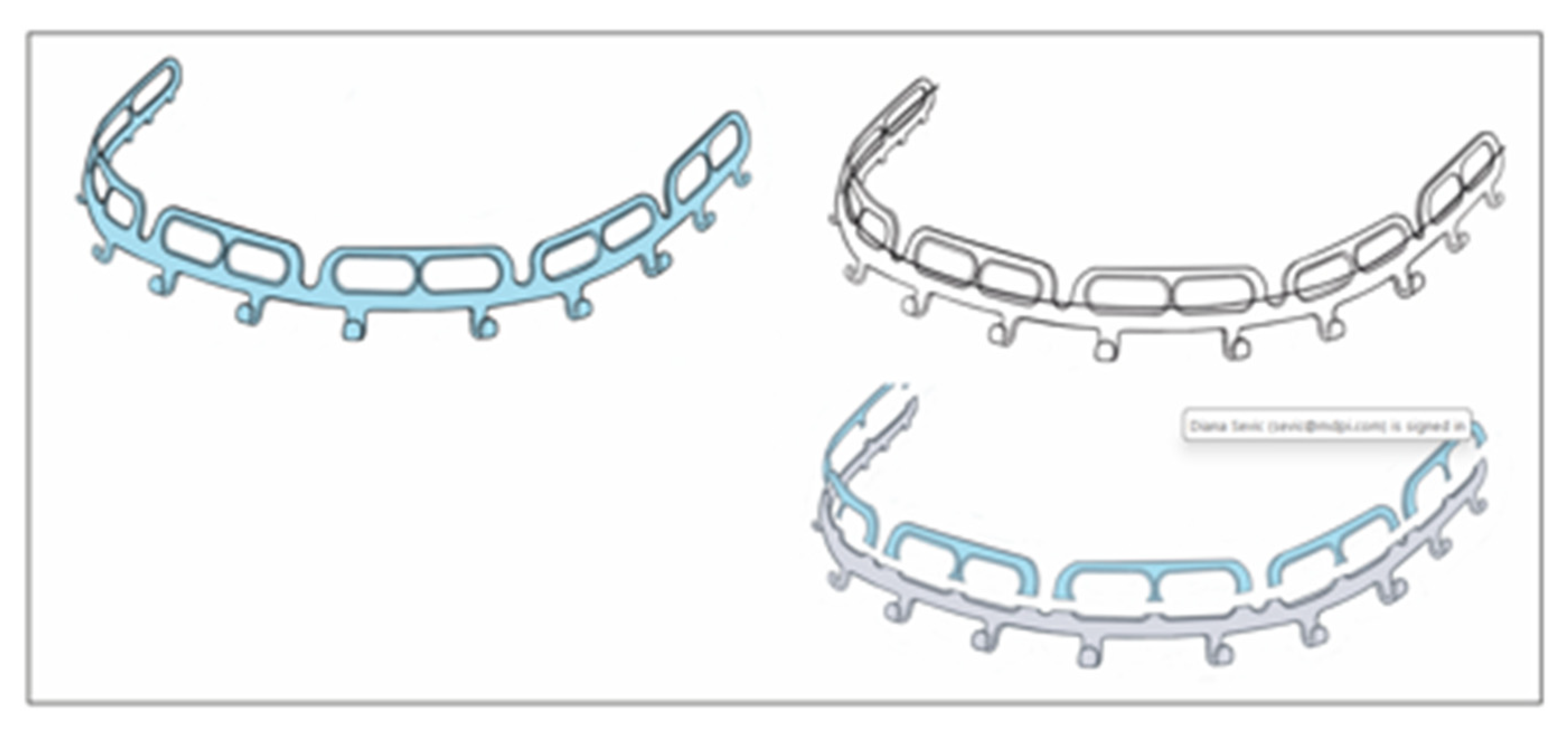
A systematic analysis of the range of movements to allow safe screw insertion sites with the OmniMax arch bar can get quite complex (Figure 11). In fact the horizontal slot pairs and the pivoting bar segments interact and are interdependent. The movements of a single segment with two combined screw insertion slots are still clear and simple. The segment can be moved 3-dimensionally which will effect the position of the horizontal slots. Finally the screws are slid inside the slots to a riskless insertion point. If a single segment is used it needs to be secured against rotation with 2 screws - 1 in each slot (Figure 10 and Figure 11).
With movements of a succession of segments (≥ 2 or more) the intermediate junctions act as articulations, allowing for pivoting around all three axes of rotation. Complicating the process further, any spin movement around an axis will indirectly affect the next (3rd) adjacent segment and carry it along the same direction in a chain reaction (Figure 11). This process again entails the need for compensating motions at the next junction. In a construct of several successive segments a single screw in either slot of a segment is sufficient for fixation of the entire device. This means in a full arch of 5 or 6 segments, 3 or 4 segments are fastened at the posterior endings and in a median or paramedian position with a screw, while the intermediate segments remain empty.
The L1 MMF System is designed as a multicomponent system consisting of a fundamental bar unit derived from a conventional Erich arch bar and an ensemble of vertically arranged members, the mounting or slider plates (Figure 12) The rack edge of the bar unit is segmentalized by intermediate wire hooks into consecutive rows toothed with rectangular tabs and gaps. The central segment of the bar unit contains a trident process (Figure 6B) with two outer appendages and an inner rectangular tap formation. The elongated trident in the middle of the bar unit serves to define the midline of the dental arch as well as leveling the bar at an appropriate vertical height.
The rack profiles on either side of the central segment provide transverse guiding lanes for the slider plates.
The slider plates have a two-leg slot extension to snap into one of the continuous rectangular “tab and gap” (= tooth) spacings along with the rack edge in the bar sections, similar to a gear mechanism. The back and frontside of a plates‘ coupling portion enclose the bar unit like an oval tube (Figure 6A, Figure 7 and Figure 12).
One slider plate is pre-assembled per segment.
Therefore two chained segments is the shortest applicable partitioning of a L1 MMF bar.
The simplest way to remove a slider plate is by shortening the bar medial to a wire hook stop. The slider plate can then be removed from the bar and must not be cut and bend open.
A L1 MMF bar unit – anatomically adapted in length and curvature - is applied via the slider plates, which can move transversely. Each plate is brought into a position, in which the screw receiving hole lies above a safe interradicular space and the two-leg slot is engaged within the rack.
The mechanical interdigitation (= plug connection) between a tooth spacing of the rack and the slider plate leg extension is not a high precision fit but rather a contact relationship leaving some degree of flexibility in any direction. The slider plate can be twisted, tipped over or angulated within given constraints along the three rotational axes (Figure 13).
A plural (≥ 2) of slotted slider plates fastened under tension in diverging vector directions is required to immobilize partitions or the entire bar unit. Otherwise the bar unit could uncouple from the slots and shift relative to the slider plates inside their interior leeway spaces (Figure 6C and Figure 7). The slider plate slots are rigidly locked into the toothed spacings of the bar during the final wiring of the intermaxillary ligatures.
The “plates” of the Matrix Wave System (MWS) differ appreciably from conventional Erich arch bars. The square shaped rod profile extending in the pattern of a periodic sinus wave does not compare to the band-like framework of the Erich arch bar (Figure 14). The rod is light, quite soft and flexible, so that it is easily adapted to the dental arch.
The screw receiving (bone anchor) holes, integral to the MWS embodiments, are located in short flattened portions (‘plateaus’) within the rod which alternate with the raised Omega curve partitions.
By contrast in Erich type of hybrid devices, the holes for the bony connection are contained in vertical projections such as lugs, railings or stackable slotted slider plates.
The shortest clinically useful MWP subdivision includes the Omega-shaped segment with its cleat and the two screw receiving holes (Figure 14 and Figure 15).
A one-wavelength Omega segment can be oriented, molded (stretched apart or pinched) and adjusted in every conceivable way to bring the cleat into an appropriate position next a tooth equator in the premolar/molar region of the upper or lower jaw while concurrently placing of the screw receiving holes over an interradicular space at the mucogingival gum line.
To determine the targeting functionality of a screw receiving hole within a pluri-segmental MWP partition an appreciation of the possible movements in - at least- two consecutive wavelength MWP sections (i.e., two adjacent Omega segments) is necessary (Figure 15).
The spatial MWS pattern can be transformed with distinct bending movements and balancing motions to bring the screw receiving hole to a safe and controllable site or move a cleat attachment into a favorable position along the tooth equators.
3.14. Bony Fixation / Hybrid Retaining Locking Screws
Bony fixation of the hybrid arch bars or MMF devices at the level of the attached gingiva above or below the mucogingival gum line is essential to prevent or reduce granulation tissue and mucosal overgrowth of the screw heads.
This feature is principally workable for all 4 commercial MMF hybrid systems. The overall height profiles of the devices do however vary and a low size vertical embodiment may not be suitable to bridge the distance between the gum-line and the tooth equators. Here the hooks or cleats for the intermaxillary ligatures are ideally positioned for biomechanical efficiency (Cornelius et al. 2024, Part I) [1]. An upward or downward shifting of the bony fixation level brings changes to the relative position between the bar units of the hybrid devices and the gingival margin, the tooth necks or the lateral crown surfaces. In the worst case the flat band of the bar unit covers and possibly impinges large areas of papillary and free marginal gingiva. This can lead to, impaired oral hygiene and with food impaction, debris and plaque accumulation.
The attached gingiva has a keratinized epithelial surface which is better suited for these mechanical stresses than the mobile alveolar mucosa.
The width of the attached gingiva on the buccal /labial side can vary greatly between individuals and within an individual relative to tooth positions within the dental arch. With healthy periodontal conditions the maximum amounts of the buccal/labial attached gingiva is to be expected along the maxillary and mandibular incisors (lateral > central), followed by the canines, first molars, second and first premolars (Ainamo et al. 1981 [47], Anand et al. 2022 [48]). The attached gingiva narrows next to the frenula and buccinator muscle attachments (Ainamo and Löe 1966) [49]. Altogether maxillary teeth have wider zones of attached keratinized gingiva than the corresponding teeth in the mandible. There are no gender specific width differences (Ainamo and Löe1966 [49], Jennes at al 2021 [50], Anand et al. 2022 [48]). The zone of the attached gingiva widens in adult age with the most progression between the third and fifth decade of life (Ainamo et al. 1981) [47]. Thick periodontal phenotypes seem to be associated with a greater width of the attached gingiva (Vlachodimou et al. 2021) [51].
A vulnerability of the different periodontal phenotypes (thin versus thick attached mucosa) to long-term penetration by the hybrid MMF retaining screws has not been explored in the literature.
Conventional screws to fix hybrid MMF devices risk compressing the gingival soft tissues but also trigger disproportionate mucosal overgrowth as exemplified in several studies (Rani et al. 2018 [19], Sankar et al. 2023 [23], Burman et al. 2023 [24], Table 2)
The use of locking screws for fixation of the devices provides a hovering or standoff property, so that compression and necrosis of the gingival soft tissues can be inhibited. A secure standoff can also be maintained by use of a plate spacer or dedicated tool, creating a stop between mucosa and plate as the locking screws are tightened.
At first glance the design of the locking screws of the different hybrid MMF systems does not show major differences concerning the bone threads and the conical locking heads with their secondary reverse threads to that are secured into the plate holes (Figure 16).
The ability for engagement at variable angles and angular stability are valuable features for mechanical interlocking between a screw and plate. The Stryker SMARTLock brochure refers to pioneering work of D. Wolter (US Patent No. 4794918 [52], Wolter et al. 1999 [53]) on internal fixator systems for osteosynthesis, so that a screw insertion and stable fixation with a slight inclination to the perpendicular axis of the hybrid MMF plate is admissible. Another indication is the tapered design of the conical locking heads with incremental sizes of the truncated threads.
The locking head of the OmniMax locking screws has a cylinder shape along with truncated V-threads of identical size in parallel. The vertical height as well as the diameter of this cylindrical locking head exceeds all other locking screws of commercial MMF hybrids (Figure 16).
The OmniMax locking screws are best inserted at right angles to the slot or plate embodiment thereby driving the plate safely into the annular retention groove just below the screw head and achieve optimal seating and angular stability for the soft-tissue standoff.
Once seated perpendicularly, the standoff of the bar can be adjusted upwards or downwards with turns of the screw into or out of the bone.
However a stripping of the bone threads compromising the grip of the screw shaft in the bone can occur.
The OmniMax slots are beveled, so that a screw insertion at angles up to 10 degrees is possible. Excess tilting and irregular (non-collinear) alignment between the screw’s locking head and the beveled slot, however, will cause friction, jamming and cold welding of the colliding fringes before the terminal standoff position and maximum depth into the plate is reached.
The position of the plate above the soft tissue surface also depends on the degree of screw angulation and twisting. A lengthways screw deviation may be less relevant, since the slots do not form a closed ring around the threads of the locking head like a plate hole.
Interestingly D. Walter (1999) [53] intentionally relied on friction grip effects to realize the locking mechanism. Due to differing degrees of hardness – harder titanium self-tapping screws ground into a softer Titanium plate to create permanent bonding.
The L1 MMF locking screw has a pronounced conical locking head with V-shaped threads permitting an insertion at variable angles. In addition the slider plate with a beveled screw receiving hole is separate from the MMF bar/rack and provides three dimensional moving options (Figure 13). Thus the slider plate position can flexibly adapt in space between the conical locking head and the coupling site at the bar /rack to counterbalance angular deviations and allow for the desired standoff. Given these multiple interfaces for offset, the L1 MMF locking screw will consistently lift the slider plate until it is flush beneath the flat screw head.
The Matrix Wave locking screw features a conical locking head with sharp V-shaped thread circles of equal size on top and on bottom and larger threads bulging at the center. Distinct from the other three commercial hybrid MMF systems the screw receiving holes of the MWP begin with a bevel (countersink) at the top side and continue into two tapered threads. The reciprocal interplay between the conical locking head and the hole threads allows for fixed angles up to 15 degrees.
With any larger deviation from the vertical axis, the screw insertion will come to a standstill because the threads of the conical locking head and the plate hole threads no longer fit together and become crossed. This could be an issue with the plate to contact the mucosa or the standoff height be unacceptably low. Overtightening of the screws causes the MWP to rotate. So in the final phase of insertion each screw must be gently secured to prevent mechanical damage to the plate, locking hole, screw or bone.
In point of fact the vertical height of the conical locking heads differs and decreases in the following order OmniMaxTM MMF System (Zimmer Biomet) – 2.5 mm, > SMARTLock System (Stryker Inc., Kalamazoo, MI, USA) – 1.5 mm = Matrix Wave MMF System – 1.5 mm, > L1 MMF System ( (KLS Martin) – 1.4 mm.
In principle higher locking heads enable larger spaces between the plate/bar and the mucosa. The overall design and geometry of the interface between locking heads and screw receiving hole is certainly a cofactor in predicting standoff.
How much standoff distance is adequate to prevent adverse tissue effects is not yet determined but might be forthcoming before long. The width of coverage of the periodontal transition zone to the tooth necks by the extent of the bar/rack/device will also be implicated in this problem.
At present it is recommendable to obtain the maximal standoff in clinical situations.
The threaded shafts of MMF screws from the hybrid MMF device league serve for bone insertion. They all have single-start threads which are oriented in right handed direction. The thread design is fine-pitched, straight along the cylindrical shafts and tapered towards the screw tips as in wood screws.
The cross sectional shape of the threads of all four hybrid MMF screws are triangular (Figure 16). The V-shaped bone threads of the SMARTLock screw are truncated and thereby have a trapezoidal profile which offers high strength. The L1 MMF locking screw as well as the Matrix Wave screw have sharp V-threads while the threadform of the OmniMax screw shaft is scalene. The latter thread profile is asymmetric having one square face opposed to a slanted flank, similar to a saw tooth.
The outer diameter or major thread diameter of the SMARTLock, OmniMax and L1 MMF locking MMF screw shafts is 2.0 mm while the Matrix Wave screw is 1.85 mm.
The SMARTLock and L1 MMF locking screws come in two overall lengths of 6 and 8 mm. The manufacturers specifications on the lengths of the OmniMax and the Matrix Wave locking screws do not contain the height of the conical locking heads and screw heads. The OmniMax screws have bone insertion shafts in three lengths – 7.0 mm, 9.0 mm and 11.0 mm. The Matrix Wave locking screws are available with a shaft length of 6 mm or 8 mm.
3.15. Locking Screws Comparison
The OmniMax and L1 MMF screws have small annular grooves underneath the screw heads.
A noteworthy feature of the Matrix Wave locking screws is a relatively large recessed neck underneath the prominent cap-shaped head. The MWP locking holes are engaged in the plateaus below the recess level and keep the neck areas available for bridal wires, supplementary intermaxillary cerclages (Figure 17) or elastic loops.
The screws of all four hybrid MMF systems have raised flat disk-like or cap-shaped heads with cruciform recesses, which are countersunk in the L1 MMF and the Matrix Wave locking screws.
All hybrid MMF systems locking screws are self-drilling.
The manufacturers specifications in the brochures and technical guides are limited in details of the technical screw parameters such as thread angles, minor thread diameters, pitch angles, pitch diameters or lead and their impact on the lifting performance and on the locking mechanisms.
The design (e.g., single bevel versus plural threads) and mechanical (e.g., shear strength) properties of the screw receiving hole in the hybrid MMF system require consideration in relation to matching of the components, their precision fit and the stability of the standoff.
The assembly of several (≥ 2) MMF locking screws and hybrid plate/bar segments produces a compound or monobloc construction, – oftentimes labeled as ‘tension band’ – wherein all screws effectively behave in unison.
The MWPs require bridal wires between neighboring screws to provide a transverse monobloc- or indeed a tension band function if an intermediate fracture line is crossed to prevent splay.
The number of locking screws for osseous anchorage fundamentally determines the stability of a hybrid MMF framework. The number of locking screws which has actually been used, is generally referred to as for installation of the hybrid MMF bars/devices per arch or per case. For SMARTLock bar applications the number varies between 5 to 7 per arch or 10 to 12 to 14 per case (Table 2).
A minimum of 3 screws per bar is recommended for the fixation of the OmniMax System. No more than two consecutive slots of a bar should be left empty. For the use of a bar at full length (6 segments with 12 slots) the later ruling (OmniMax Application Guide - Zimmer Biomet) would require 4 screws per bar at least.
A minimum of 5 fixation points per bar of the L1 MMF System via coaction of slider plates and locking screws is endorsed (L1 MMF Technique Guide - KLS Martin). This applies for the 7-hole and the 9-hole length. The handling at shorter lengths is not disclosed.
Matrix Wave mono- or multi- segment partitions require a locking screw insertion in each locking hole. To leave out a screw at a fastening locus would weaken the ensemble.
It is clear that reducing the screw number shortens the placement time for a hybrid MMF system. The reduction in screw number must not jeopardize stress-shielding of the entire assembly or drop its rigidity below the loading thresholds of the jaw opening muscles (Kendrick et al. 2016 A [17], Aslam-Pervez et al. 2020 [26]).
However the knowledge of physiological jaw opening forces in healthy adults is very limited. Technical measurement tools and assessment protocols vary greatly in the literature, consequently the data are far from reliable (Greenbaum et al. 2022) [54]. There is a wide range of variation, for instance in a population of 149 participants aged between 20 – 60 years men had greater opening forces with a median of 79.0 N, an IQR (Interquartile Range) of 63.86 N and a maximum value of 166, 61 in comparison to women with a median of 41.16 N, an IQR of 30.44 N and a maximum value of 157.77 N (Brunton et al. 2017) [55]. This lack of solid physiological references may be one of the reasons that the limits of stability and resistance of hybrid MMF systems to jaw opening forces have not yet been simulated in vitro or in bench studies.
The fixation of the hybrid MMF bars/devices with an increasing number of locking screws will progressively enhance the robustness of the monobloc framework and produce a hardware and bony structural unit that is able to resist pull out forces and slippage.
Failure of the monobloc can occur if the locking screws have been inaccurately or loosely engaged into the beveled or threaded holes/slots of the bar or rod, respectively.
In mechanical overload, the tightly locked screws will either break or dislodge from the bone combined with the framework.
In contrast with conventional screw fixation the load accumulates serially and the pull out proceeds sequentially one screw at a time.
4. Discussion
Arch bars or MMF devices with hybrid or bimodal character can be defined as a blend of conventional arch bar or rod-shaped embodiments outfitted with elements (e.g., plate /screw receiving holes, lugs, slots) to provide direct bone support by means of screw fixation laterally in the alveolar process.
Self-made hybrid arch bars and above all the commercial versions of hybrid MMF devices are often dubbed “easy arch bars” to underscore that they address some major drawbacks of tooth-borne conventional arch bars (EAB) - these include the time requirements for application and removal, the risk of wire-stick injuries and periodontal impairment/damage in long term applications.
Because hybrid arch bars / MMF systems are likely to gain increasing importance in the facial trauma care because of potential advantages over former techniques for jaw immobilization, this review explores the current landscape. All available publications (studies, reports, US patents and white papers) on the subject have been considered without respect to a supposed level of evidence and assessing a risk of bias analysis.
Self-made hybrid arch bars (Table 1) correspond to conventional Erich arch bars (EABs) modified by simple means - drilling of additional boreholes for screw insertion and occasionally unbending or opening of wire hooks, winglets or the like (Figure 1). A few publications point out their efficiency and potential clinical benefits (Table 1).
Moreover there is a collection of commercially available MMF systems - the Stryker SMARTLockTM Hybrid MMF System (Stryker), the OmniMaxTM MMF System (Zimmer Biomet), the Matrix WaveTM MMF System (DePuy-Synthes) and the L1 MMF System (KLS Martin North America), the latest patented hybrid MMF device (US Patent No.10,470,806 B2, 12 November 2019) [12], which has not been rolled out internationally yet. These devices present a league of its own in terms of design, clinical performance and last but not least cost.
The vast majority of publications deal with the SMARTLock MMF System (Table 2) reporting the outcomes of relevant clinical parameters.
Almost all authors acknowledge the SMARTLock System as a comparable alternative to conventional Erich arch bars or MMF screws with some even endorsing the hybrid system as the better option.
The disparity of the SMARTLock system compared to the number of publications on the other league members is great – there is only one retrospective clinical study (Aukermann et al. 2022) [39] and an interim report of a clinical trial (Morio et al. 2018) [44] for the OmniMax System, one study on the Matrix Wave System (Kiwanuka et al. 2017) [46] and no clinical data on the L1 MMF System.
The existing clinical data have been outlined in exquisite detail previously and will be only briefly be revisited here.
It is unfortunate, but the poor quality data makes a comparative clinical analysis between the different hybrid MMF systems impossible.
A comparative evaluation, both among the SMARTLock publications as well between the other hybrid systems would have been difficult from the very outset, simply because the available studies focus on different treatment methods (closed reduction versus ORIF) and different fractures patterns.
4.1. Wire-Stick Injuries
Glove tears and skin punctures have always been a significant concern in wire-based MMF applications.
So the reduction of inadvertent stainless steel wire injuries to hand and fingers would be a decisive advantage of hybrid arch bars and hybrid MMF systems (Nizam and Ziccardi 2014) [15].
The rates of percutaneous injuries (superficial or deep) in wire-based MMF procedures vary between 10 % and 37 % (Ayoub and Rowson 2003 [56], Bali et al. 2011 [57], Chao and Hulsen 2015 [16], Osodin et al. 2022 [58]). The injuries typically affect the forefingers of the working hand (Bali et al. 2011) [57]. Traditional protectives against potential blood borne infections) include wearing double gloves and/or cerclage wires with blunt tips instead of the sharp ends resulting from mechanical wire cutters (Brandtner et al. 2015) [59]. Precut cerclage wires with round or blunted ends for a greater safety margin are now in the portfolios of the medical device companies.
During intermaxillary immobilization with hybrid arch bars / MMF systems the use of wires is confined to intermaxillary cerclages, ideally with blunt tips.
It follows logically, that self-made hybrid arch bars and the SMARTLock Hybrid MMF systems have shown zero or relatively low incidences of glove tears and skin punctures (Table 1 and Table 2). In the Aukerman study (2022) [39] on the OmniMax device this issue was not addressed, however the interim outcome report on a clinical multicenter trial (Morio et al. 2018) [44] documented no glove perforations or accidental skin punctures.
In the only clinical study on the Matrix Wave System (Kiwanuka et al. 2017) [46] wire-stick punctures were also absent. There is as yet no published clinical data on the L1 MMF devices.
A summary on Wire Free Fixation is provided as Electronic Supplement (eTextBlock 3 –; Line 1689 – 1716)
4.2. Wire-Free Fixation
Historically wire-free fixation of MMF devices has come a long way.
Wire-free fixation of MMF devices started with use of the acid etch technique for direct composite or resin bonding of arch bars in the late 1980s (Baurmash et al. 1988) [60] Here a fine orthodontic mesh was welded to the flat inner surface of a conventional EAB to create a suitable interface for the adhesion.
A wire free MMF device in a so-called “bracket- bar’ design was introduced soon thereafter (Sindet-Pedersen et al. 1990) [61]. This specialized bar with a continuous series of oval-shaped perforations was contoured to fit passively to the teeth and was resin bonded.
Both of the author groups advocated installing plate segments in lieu of a full arches (Baurmash 2006 [62], 2007 [63], Chandan et al. 2010 [64]).
The authors indicated adequate fixation, better oral hygiene due to less hardware, suitability in deep bite and the advantages in reduction of mandible fractures with sectional bars. They discouraged fracture reduction through these bar segments because the resin bonding might not withstand the forces during traction. Once the reduction was completed by manipulation of the bony fragments and the occlusion was reestablished the sectional bars were joined over the fracture site with wire (!) loops topped by a resin deposit.
Another wire-free method of arch bar fixation to the dentition used a bilateral integration of a tiny turnbuckle into the longitudinal rod of a Schuchardt arch bar. The ends of the rod completely encompassed the terminal tooth crowns – usually molars – including their lingual or palatal aspect in a belt-like manner. The arch bar was clamped on the dental crown surfaces by tensioning the turnbuckles to shorten the rod length. The posterior clamp fitting attachment was enhanced by filling the interdental spaces with auto-polymerizing acrylic resin (Hönig 1991) [65]. Potentially adverse reactions of the teeth (unwanted movements, extrusion) to clamping forces were downplayed in the author’s discussion.
4.3. Speed of Application
There is no doubt the technical features of the hybrid arch bars / MMF systems and the simplicity of handling speed application and result in savings of operating time. Omitting the circumdental wiring of the arch bars, however, is not the only determinant for the acceleration of the MMF procedure. Other factors including the length or segmentation of the hybrid arch bar / MMF system, difficulty in contouring, the number of screws, the identification of a suitable screw insertion site, the maneuverability and adaptation of the bone supporting components (lugs, slots, locking hole portion, slider plates) and manual or motorized screwdriver insertion (King and Christensen 2019) [21] may all contribute to efficiency.
As a consequence, the average time to install a hybrid MMF assembly can vary greatly. For the SMARTLock System the time for the inserting of 5 retaining screws per arch ranged from a low of 6.9 ± 3.1 minutes (King and Christensen 2019) [21] to a high of 56.1 ± 15.4 minutes (Edmunds et al. 2019) [27] (Table 2). The time savings for the SMARTLock Hybrid System in comparison to EAB’s ranged from 18.2 minutes (Rani et al. 2018) [19] to 42.6 minutes (Edmunds et al. 2019) [27].
For the OmniMax MMF Hybrid System the mean application time of 12.8 ± 3.0 minutes was documented in the interim trial report (Morio et al. 2018) [44]. There are no data on the time requirements for the Matrix Wave System and the L1 MMF System.
It is noted that the application time for pure MMF screws would be shorter than for hybrid arch bars or MMF devices, since preparation, contouring, placement and monobloc building with extra screws is omitted (Roeder et al. 2018 [25], Edmunds et al. 2019 [27], Aslam-Pervez et al. 2020 [26]).
Whenever new technologies like a hybrid arch bars/ MMF systems are introduced into routine use, the time required for applications is of interest to assess economic viability. The cost-effectiveness of the SMARTLock Hybrid MMF System was scrutinized at many US centers with inconsistent results (Chao and Hulsen 2015 [16], Kendrick et al. 2016 [17], King and Christensen 2019 [21], Edmunds et al. 2019 [27]). A cost reduction can only be expected when the device cost incurred for the surgery provides sufficient return in time savings of the surgery (Khelemsky et al. 2019) [22].
The main barrier to use Hybrid MMF devices on a global scale is cost. The disposable hardware carries price tags between $ 500 and $700 per intervention, what takes them out of reach for many surgeons in poor resource parts of the world.
4.4. Segmentation
Partitioning of the commercial hybrid MMF systems into short segments as proposed by our group (Cornelius et al. 2024, Part I) [1] potentially offers a cost reduction, but depends on the technical characteristics of the segment and whether it has adequate residual stability (see above – technical features). The use of short segments of hybrid MMF systems is not indicated in complex fracture patterns (multiple fractures, multifragmentation) for certain. Determining segment lengths will vary according to location, fragmentation and morphology of facial fractures as well as the plans for intraoperative and postoperative MMF.
4.5. Removal
In general the time for removal of hybrid arch bars / MMF systems assumingly is shorter than for wire-secured EABs, though the duration was not regularly recorded in the SMARTLock studies (Table 2). A painless and efficient removal in the office is preferred. The need for anesthesia (topical, local or general anesthesia) during the systems’ removal is more important than minor differences of time, as the need for anesthesia generates additional costs in the operating room. Obtaining access to screw heads overgrown by mucosa may require small incisions under local, with longer procedure times (Hamid and Bede 2021 [33], Burman et al. 2023 [24]).
4.6. Screw Insertion Sites
The primary stability of a bone screw depends on adequate thickness (1- 2 mm) and density of the osseous cortex, the angulation and intrabony length of the screws and the depth of insertion (i.e., monocortical or bicortical) (Brettin et al. 2009 [66], Yang et al. 2015 [67]). Fostered by the popularity of miniscrews for anchorage in modern orthodontic therapy, the intraoral transmucosal (non-incision) insertion sites for bone screws have seen intensive research in vitro and clinically by means of multiplanar and 3D imaging techniques (CBCT, CT).
Orthodontic miniscrews have similar diameters between 1.2 mm to 2 mm as specialized MMF screws (core diameters 1.35 mm – 1.6 mm and thread diameters up to 2 mm) or as the intrabony shaft of the fixation screws for hybrid MMF devices (core diameters 1.5 mm – 1.8 mm and thread diameters between 1.85 mm – 2 mm). So there is a valid reasoning to transfer the findings for transalveolar screw application in the adult dentition from the buccal / labial side. The ideal low-risk placement of locking screws with hybrid MMF arch bars or devices can be compromised by the fracture pattern (fragmentation and fracture line within or in direct proximity to the preferred insertion sites).
The quantity and quality of the interradicular spaces for the placement of orthodontic miniscrews has been investigated in great detail. In this sense the values of the mesiodistal and bucco-/labio- lingual dimensions were accurately collected and listed in extensive spreadsheets for the anterior (Alsamak et al. 2013 [68],
Shalchi et al. 2021 [69]) and the posterior buccal interradicular spaces of the maxillae and mandible at incremental steps from the alveolar crest or cemento-enamel junction towards the apex (Poggio et al. 2006 [70], Haddad et al. 2019 [71]) according to age, gender (Fayed et al. 2010) [72], ethnicity, dentoalveolar arch form and facial growth pattern (Limeres Posse et al. 2022 [73], Hasani et al. 2023 [74]). Furthermore the interradicular buccal cortical bone thickness, the density of the compact bone at the labial / buccal and lingual / palatal aspect, respectively and the density of the cancellous bone inside the cortical bone plates, i.e., the intercortical density, in respect of the demographicvariables were recorded (e.g., Park and Cho 2009 [75], Li et al. 2014 [76], Nucera et al. 2017, 2019 [77]).
The extensive data from the studies referenced above on suitable placement of orthodontic miniscrews can be condensed into a few recommended “safe” or “rather low risk” zones.
The preferred target sites for screw insertion from the buccal / labial side in in the adult dentition – as per relevance for the placement of specialized MMF or hybrid MMF Locking screws – occur in the following interradicular alveolar bone locations (Table 3).
The distance from the alveolar crest or the cemento-enamel junction towards the root tips is important to assure sufficient width and accessibility to interradicular bone spaces and stability of miniscrews (Haddad and Saadeh 2019) [71].
Interradicular spaces in both dentoalveolar arches expand in the apical direction with the exception of the maxillary intermolar spaces, which run parallel (Pan et al. 2013) [78].
4.7. Oral Mucosa
The type of oral mucosa along the vertical extent of the buccal /labial alveolar ridges plays a definitive role for miniscrew mid/ long term failure rates.
Placement into the mobile alveolar and vestibular mucosa beyond the mucogingival line was associated with increased infection rates and failure compared to screw anchorage within the attached (keratinized) gingiva and at the mucogingival junction. (Cheng et al. 2004 [80], Palone et al. 2022 [81], Xin et al. 2022 [82]).
As outlined above, the screw fixation of the hybrid arch bars or hybrid MMF systems within the attached gingiva up to the level along the mucogingival gum line is important in preventing mucosal overgrowth of the screw heads.
The greatest bone width of the interradicular spaces, however, does not coincide with the coverage by attached mucosa in the coronal third of the tooth roots.
The retromolar region within the confines of the maxillary tuberosity provides only a small amount of poor quality bone.
Contrarily, the edentulous alveolar area distal to any last standing tooth in the lateral mandibular tooth row including the retromolar region and the anterior ramus offers cortical bone that is thick very dense (Poggio et al. 2006 [70], Mehta et al. 2022 [83]).
In facial fractures affecting the occlusion it is essential to consider the course of the fracture lines through the alveolar bone and adjacent to tooth roots. The need for direct reduction and integration of the fragments into the hybrid MMF monobloc is prioritized resulting in the potential need to insert the screws into less favorable sites with greater risks of tooth root injury.
4.8. Recommendations – Screw Length and Diameter
A 6 - 8 mm screw length has been proposed (Deguchi et al. 2006 [84], Park and Cho 2009 [75]), which was not unopposed in favor of longer screws (Palone et al. 2022) [81]. The recommended diameter for orthodontic miniscrews for placement in the frontal/lateral alveolar bone is 1.2 mm - 1.6 mm.
Beside the miniscrew diameter, a safe placement of an interradicular miniscre requires consideration of the “peri-implant insertion path” (Ikenaka et al. 2022) [85]. This path consists of the bone/tissues between the screw and the lamina dura.
Falci et al. (2015) [86] address this insertion path as ‘clearance around the screw needed to preserve periodontal health and screw stability’. The authors assumed a sleeve or clearance of 1 mm adjacent to the outer (thread) screw diameter to define the measure of the insertion pathway cylinder apart from its length.
The proximity up to actual contact and its extent of miniscrews to the tooth roots is a major risk factor for long-term failure of skeletal anchorage and screw loosening. It stands to reason that if the body of miniscrews overlaid the lamina dura in their full length at postoperative control in dental x-rays, the screws had the lowest success rates compared with screws absolutely separate or just touching the lamina in one point with their tip (Kuroda et al. 2007) [87].
4.9. Imaging
The anatomic variability of the alveolar anchorage sites for screws can be great in an individual patient. When low-dose multiplanar imaging techniques reaching a sub-millimeter scale are available, it should not be simply relied upon the general recommendations for (mini-)screw placement (Martinelli et al. 2010 [88], Bhalla et al. 2013 [89]).
A systematic review validated distinct advantages of CBCT for interradicular (mini-)screw preinsertion planning over two-dimensional/panoramic radiographs.
4.10. Tooth Root Injuries
Tooth root injuries are a recognized screw associated problem and a specific complication of transalveolar anchorage of hybrid arch bars / MMF devices (Wilt et al. 2019) [29].
Radiographically, minor dental root lesions are located peripherally over the cement and/or dentin and do not involve the pulp chamber. Major lesions project centrally onto the pulp chamber indicating a perforation, onto the entry zone of the neurovascular bundle within the root tip region or as root fragmentation.
The incidence of clinically relevant damages after placement of hybrid arch bars (Table 1) and MMF systems (Table 2) appears to be low, but it is important to recognize that minor and major dental root lesions are usually not distinguished in the reports. Several clinical studies on the SMARTLock System have not detected tooth damages in postoperative imaging (Chao and Hulsen 2015 [16], King and Christensen 2019 [21], Edmunds et al. 2019 [27], Hamid and Bede 2021 [33], Burman et al. 2023 [24], Elhadidi et al. 2023 [11]) A few other studies did not refer to tooth root injuries at all (Hassan et al. 2018 [9], Khelemsky et al. 2019 [22], Roeder et al. 2019 [25], Kiwanuka et al. 2017 [46], Aukerman et al. 2022 [39]).
The dental pulp status after dental root traumatization cannot be assessed by one single method – pulp vitality testing refers to the vascularization and pulp sensibility to sensory innervation. Radiographs confirm dental root trauma morphologically but are not diagnostic of pulp vitality or death. Commonly sensitivity tests are employed in the form of thermal tests or electrical testing, both methods eliciting a pain response as long as the pulp is vital and not irreversibly damaged.
Non-invasive objective testing of pulpal blood flow can be performed by Laser Doppler flowmetry, Spectrophotometry or Pulseoxymetry all of which requiring specialized technical equipment, training and expertise.
A reliable long-term prognosis of viability for asymptomatic teeth with radiological root damage unreactive to sensory testing is not available. Therefore a watchful waiting approach for an injured tooth to become symptomatic is justifiable given that, spontaneous repair is possible.
Three experimental studies in mature beagle dogs demonstrated an almost complete regeneration of the injured periodontal structures (cementum, periodontal ligaments and bone socket) after intentional damage by miniscrew insertion (Asscherickx et al. 2004 [92], Brisceno et al. 2009 [93], Dao et al. 2009 [94]). Histologic sections of the damage sites were evaluated from 6 to 18 weeks either subsequent to removal of the miniscrews (Asscherickx et al. 2004 [92], Brisceno et al. 2009 [93]) or with leaving them in situ (Dao et al. 2009) [94]. Damage ranged from minor interruptions of cementum to pulp invasion and root fragmentation.
Restorative formation of new bone, periodontal ligaments and cementum was observed in high percentages of the teeth, with increasing percentages of cementum repair of resorption zones over time. With the screws left in situ there was no external resorption or inflammatory infiltration and/or necrosis of the pulp.
After early screw removal abnormal types of healing were present in a third of teeth, including defective regeneration of the periodontal ligaments and bone, ankylosis at fragmentation sites and absence of repair when the pulp was affected.
Iatrogenic complications like tooth root injury, despite a presumed low risk level (Table 2) can challenge a treatment and elicit skepticism.
Moreover endodontic treatment, tooth removal, prosthodontic or implant replacement can create significant costs.
However, tooth root damage is principally preventable by the design features of the hybrid MMF devices.
4.11. Targeting Function – Juxtaposition of the Hybrid MMF League Members
The screw receiving holes have received little attention as targeting facilities for pinpointing safe interradicular space for the insertion of the fixation screw.
A targeting function is very limited or nonexistent in self-made hybrid arch bars, where the row arrangement of screw receiving holes along the rigid bar does not permit point by point alterations, only allowing for shifts or rotational movements in one piece.
The design of three of the four commercial hybrid MMF devices – SMARTLock Hybrid MMFTM device (Stryker Inc., Kalamazoo, MI, USA), OmniMaxTM MMF System (Zimmer Biomet) and L1 MMF System (KLS Martin) derives from the band-like conventional Erich arch bar (Figure 8, Figure 10 and Figure 12).
The fundamental bar units of these three MMF systems are equipped with distinguishing extensions or suprastructures, to gain suspension from the maxillae or foothold in the mandible. The extensions are set up as a series of pillars or lugs (Figure 8), paired slots (Figure 10) or stackable mounting / slider plates (Figure 12 and Figure 13). The suprastructures contain the screw-receiving holes or slots for bone anchorage. In contrast the screw receiving holes in the Matrix Wave Plates are not carried in extension arms but rather occur in a repetitive pattern in the slimline rod embodiment at regular distances along the wave length (Figure 14 and Figure 15).
Figure 12.
Schemes of an L1 MMF device - oriented and conformed in curvature for maxillary application – stylized schemes of the embodiment. (left) Assembly of arch bar unit and multiple mounting/sliding plates. Sliding plates serve as footholds for the arch bar and for bony anchorage. (inset- orange) Sliding plate (simplified initial version) with screw receiving hole and coupling unit. (right) Blow-up /cutaway illustration detailing the features which convert a conventional dentally fixed Erich arch bar into the bone-anchored L1 MMF device: tabs and sliding plates. Source/origin of Figure 12: 1st version for the embodiment in Patent No. US 10,470,806 B2 – 12. Nov 2019 [15]. Schematic Drawing – C.P. Cornelius.
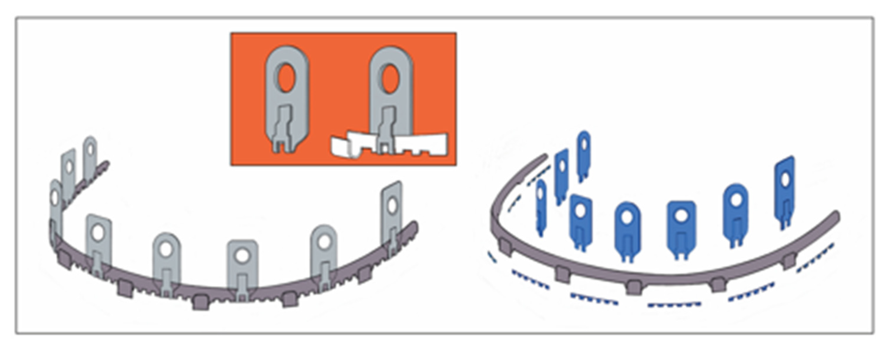
The circular holes of the extensions can be moved to spot the optimal interradicular position for the screw insertion.
The heterogenous geometry of the suprastructures among the hybrid MMF systems members however may restrict potential 3-dimensional spatial orientation and reach. It is not possible to objectively validate and quantify these technical differences. Detailed information on the overall geometric layout, contours, measurements and material properties (e.g., malleability, elastic modulus) of the devices would be required to conduct any simulation or comparative analysis. In the absence of such data and necessary high-tech laboratory equipment or software solutions, we present graphical displays of the four commercial MMF systems. We estimate the mechanically plausible degrees of translational and rotational movements as a preliminary evaluation. These movements were depicted in cross hair target boards as a synoptic template for juxtaposition of the systems (Figure 9, Figure 11, Figure 13 and Figure 15).
This illustration was not intended to identify a factual superiority of any the hybrid MMF league members or deliver a performance ranking, but rather to provide a visual reference for selecting a hybrid MMF device type for routine use depending on personal preferences.The clinical utilization of the SMARTLock MMF System will remind surgeons of long established routines with EABs. This familiarity with EABs is supposedly one of the reasons for the high acceptance and great popularity of the SMARTLock MMF System.
Nonetheless, the system requires the reconsideration of the vertical placement relative to the gum line. From a biomechanical perspective the bar units and connecting hooks should be along the tooth equators. For periodontal and oral hygiene aspects, the transition zone between the tooth necks and gingival margins should be left widely uncovered. These transition zones should be bridged only intermittently by lugs or another kind of extension piece passing towards the attached gingiva.
Correspondingly the up- or downward alignment of the SMARTLock bar/plate must be coordinated with the height of the lug extensions. Since the height is fixed, the bending radius, and flexibility of the lugs is limited (Figure 9), so that compromises of the bar montage level may be needed to position screw receiving holes over safe interradicular spaces (Kiwanuka et al. 2017) [46].
This problem becomes particularly apparent in the anterior vestibulum of the mandible where the fixation screws are often placed into the mobile mucosa inferiorly to the root tips of the lower incisors (Figure 2A). The use of the larger (regular) of the two SMARTLock Hybrid plate versions (Kendrick et al. 2016 A [17], 2016 B [18], Marcus and Powers 2016 [14], Stryker SMARTLock Brochure accessed February 2025) may help to alleviate this issue.
As its name implies, the OmniMax MMF System possesses nearly omnidirectional bending capabilities with the prerequisite that several bar segments are utilized in a row (Figure 10). A single bar segment carrying two screw slots is bendable out of plane and can be torqued. Such a segment can be displaced in all spatial dimensions to conform with the anatomy of the dental arch. The paired slot openings directly abutting alongside the bar segments (mounting tabs) provide gliding tracks for side shifting of the locking screws.
As a matter of fact the low constructional height of the OmniMax embodiment does not allow for a placement of segments at the level of the tooth equators from the very outset (Figure 4A and Figure 5A).
Instead the narrow two-tier design demands a positioning at or over the tooth neck/ gingival margin transition zone. This does not differ conceptionally from conventional EABS. The slots assume a targeting function only in tandem with movements of the bar segments, which set the initial framework, still with a changeable position. Then the slots will primarily demarcate a horizontal baseline (,x-axis’) for potentially safe screw insertions. The screw is then slid along the slot opening to determine the final screw insertion point.
The L1 MMF System is characterized by a bar unit separate from a plural of slider plates (Figure 12 and Figure 13). Again the bar unit is the fundamental element for the vertical placement of the whole assembly and in consequence the reach of the slider plates in their passage to the attached gingiva or the upper third of the interradicular spaces. The slider plates are horizontally adjustable (Figure 6A–C and Figure 13) guided by the rack profile of the bar unit (,x-axis’). Once the plate foots are coupled or plugged into the rail track of the bar, the maneuverability of the plates becomes restricted to rotational movements in all three axes (Figure 13). ,Sideways’ movement, i.e., rotation of the plate around the z-axis or roll, have the greatest range, it gets less for hinges around the x-axis or pitch and least for twisting around the y-axis or yaw.
Figure 13.
Schemes of the L1 MMF device - (left) Two segments of a row - frontal view, each engaged with a stackable slider plate. Left-right plate moving options within a bar segment (green arrows), (center) Cross section of a slider plate snapped on a bar unit. Leeway space inside the coupling partition (blue) extends vertically. Color coding: Slider plate: coupling portion (light grey), main body (dark grey), screw receiving hole portion (rouge); bar unit with toothed rack segments (white), rotational axes (red) (inset - right) Synoptic scheme: target board with crosshairs demonstrating possible movements of the slider plates/screw receiving holes to locate a safe zone for a screw insertion. Slider plates can be hinged to some degree along all three spatial axes. Source/origin of Figure 13: Schematic Drawing – C.P. Cornelius.
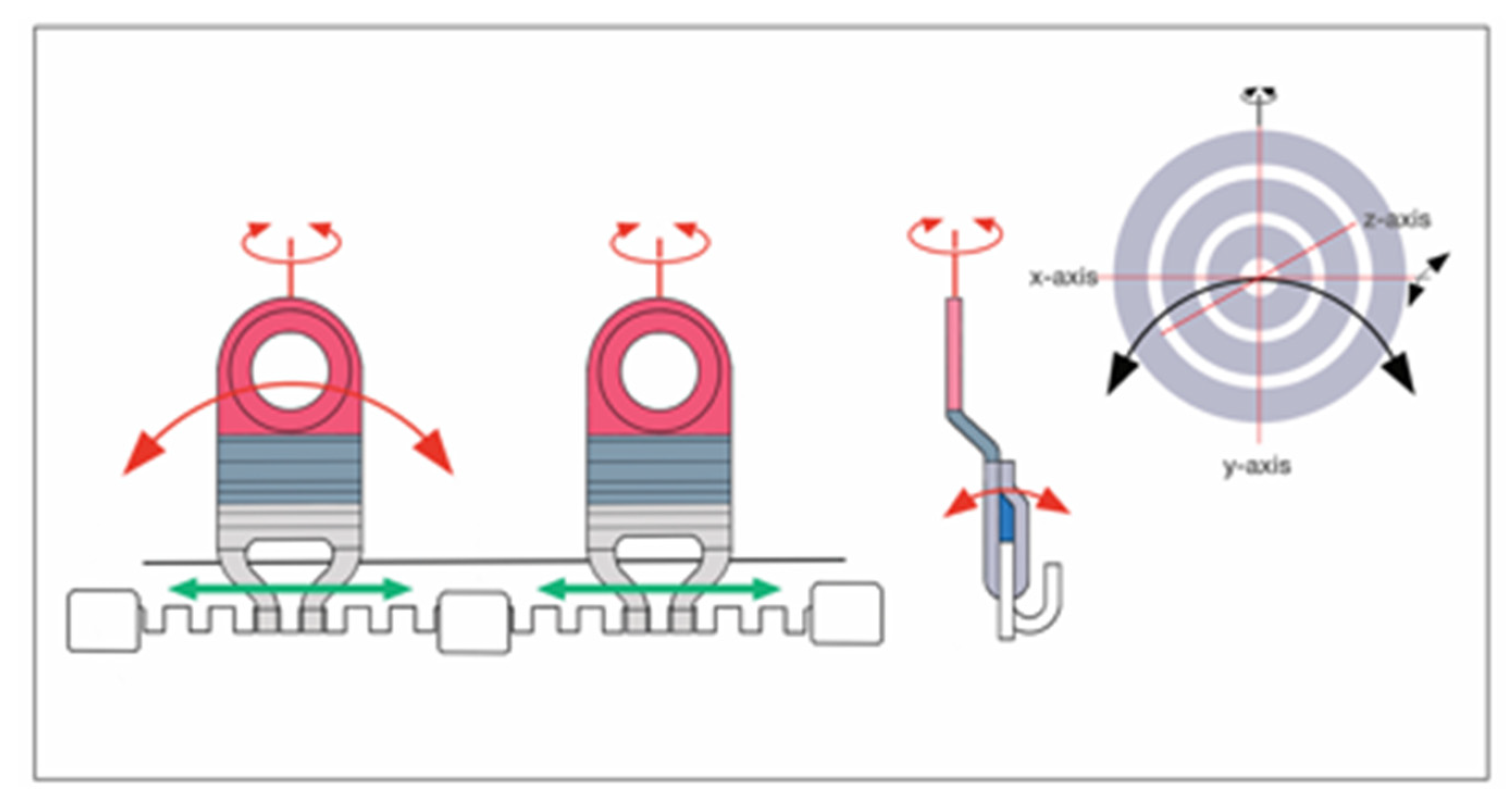
The height of the slider plate is the crucial feature for a favorable vertical placement of the devices at the level of the tooth equators and along the attached gingiva in the upper third of appropriate interradicular spaces.
A particular challenge with L1 MMF installation is the fact that one slider plate alone is not enough to maintain the bar units accurately aligned and immovably fixed in place. Rather it requires at least two slider plates in two adjacent bar sections to tighten the shortest possible bar segment. Some risk for displacement of the bar is hard to be ruled out eventually.
The design of a Matrix Wave Plate (MWP) fundamentally differs from the other hybrid MMF systems. The straight band-like arch bar has been replaced by a continuous sinus wave design of a slender rod with a square cross section (Figure 14). The sinus wave is composed of consecutive Omega segments which are highly moldable. The screw receiving holes are an integral component of the rod and accommodated within small sized tracts, the locking hole plateaus, which repeat themselves on one side of the rod at adjacent points of the same phase corresponding to a wavelength (Figure 14 and Figure 15). Each Omega segment allows for stretch, compression, torque movements and alteration of its amplitude and symmetry.
Furthermore plural Omega segments in chain are pliable between one another, so that an overall more or less irregular meandering 3D configuration can be assumed, that comfortably reaches from the tooth equators for attachment of the connector cleats over to suitable interradicular spaces. The two height versions of the MWS additionally broaden this outreach.
The individual screw receiving holes consequently have six degrees of freedom to facilitate a safe and controllable screw insertion (Figure 15).
According to the chain-link principle of the Matrix Wave MMF embodiments a bending movement between Omega segments will necessarily require counterbalance motions either within the segments themselves or along adjoining partitions to readjust the entire framework.
While bone fractures must be perfectly reduced prior to installing the bar for the other MMF hybrid systems, residual displacement of fragments is amenable to the in situ bending property of the Matrix Wave Plates (Cornelius et al. 2024, Part I) [1]. The specific serpentine design and material characteristics of the titanium framework make it possible to realign and anatomically reduce fragments after an Omega segment has been secured with a screw on each side of the fracture line. The Omega segment along with the fragments is manipulated (rotational / translational movements) until the fracture gap is closed and/or the occlusal plane is restored. In situ bending is also a useful feature for the meticulous adaptation of the Matrix Wave framework to the outer dentoalveolar relief, most importantly to bridge the distances from the tooth equators to the interradicular spaces.
It needs to be recognized that the ideal placement of hybrid arch bars / MMF systems according to optimal biomechanical and periodontal criteria is often very demanding and at times is even not possible. Compared to individual MMF screws applying hybrid devices is less elegant and more time consuming (Roeder et al. 2018).
4.12. Tension Banding
MMF screws frequently are criticized because they do not exert a tension band function (Roccia et al. 2005 [95], Rai et al. 2011 [96], West et al. 2014 [97], Edmunds et al. 2019 [27]).
This capability is seen with arch bars, hybrid arch bars and hybrid MMF devices.
Originally the term, Tension band‘ was used in connection with compression plate osteosynthesis of mandibular body and angle fractures. Compression plating with bicortical screw fixation along the inferior mandibular border generated tension forces along the alveolar ridge or retromolar region. So tension banding referred to a miniplate crossing a fracture line along the superior border at the tooth root level or in the angle region to counteract splaying when compression was applied. Acrylic wire splints (Spiessl 1989) [98] or Erich arch bars (Yaremchuk and Manson 1992) [99] have also been utilized as tension band splints. In association with tooth wired arch bars tension banding referred to the direct bracing of the teeth in the dental arch. With the advent of bone-fixed hybrid arch bars / MMF systems this exact concept is no longer applicable. In this new setting, tension banding connotes the stress-shielding effects provided by the formation of a bloc construct or external fixator (Edmunds et al. 2019 [27], Sankar et al. 2023 [23]), which is based on the locking mechanism between the framework and bone screws.
The serpentine design of a Matrix Wave Plate is not consistent with a tension band function as a bar connection in line with the fixation screws (Figure 14). This “tension band” would be antithetical due to its flexibility and in situ bending properties. However, a transverse reinforcement between neighboring screws can be created by bridal wires or interarch cerclages in a square or “mattress” arrangement encompassing four connecting cleats (Figure 17). The stability of bridal wires or interarch cerclages compared with a flat solid bar is certainly debatable. Adjustable bridal wires can be advantageous in the closed treatment of anterior mandible fractures with the Matrix Wave System, because they allow application of compression and manipulation while enhancing the stability without requiring removal of the intermaxillary fixation (Kiwanuka et al. 2017) [46]. The increased stability of this “tension banding” in its original sense enables a closed treatment in cases of two concurrent mandible fractures (Kiwanuka et al. 2017) [46].
4.13. Transoral ORIF – Vestibular Incision Placement
All hybrid arch bars / MMF systems are compatible with transoral open reduction and plating osteosynthesis. The placement of mandibular and maxillary vestibular incisions warrants careful consideration to avoid interferences with the transmucous labial /buccal entryways of the screws and the hybrid MMF hardware. To move away from interradicular screw entrance sites the vestibular incision should include a large cuff of mobile mucosa in continuity with the attached mucogingival tissues for effective closure (Nizam and Ziccardi 2014 [15], Roeder et al. 2018 [25]). Screw insertions into the alveolus close to the mental foramen should be controlled by bringing the incision lines curvilinear above the foramen to visualize the mental nerve branches and prevent injuries.
4.14. Other Associated Risk Factors and Complications
Another device specific risk factor of hybrid arch bars / MMF systems is ischemia and pressure necrosis of the gingival and /or mucosal soft tissues caused by bone anchorage (Jain et al. 2021) [31]. The damage is preventable by using an adequate standoff between the hybrid arch bar or hybrid MMF device and the soft tissue surface. All hybrid MMF league members have a locking screw–bar/rod interface to realize an adjustable standoff. Accordingly Morio et al. (2018) [44] documented no mucosal necrosis in the clinical outcomes of the OmniMax System. With the use of conventional screws for the bone fixation detrimental effects are most likely due to the absence of a conical locking head leading to excessive contact pressure underneath the bar strips or device extensions. The five studies reporting on self-made hybrid arch bars (Table 1) all used conventional screws, but none even mentioned mucosal necrosis. The same is true for the three studies employing conventional screws for the bony fixation of stainless steel facsimiles of the SMARTLock System (Rani et al. 2018 [19], Sankar et al. 2023 [23], Burman et al. 2023 [24]), so that the concerns on tissue necrosis are not yet substantiated by clinical experience.
Nonetheless an inverse correlation between standoff and mucosa migration over the retaining hardware extensions and screw heads can be presumed. The rate for mucosal overgrowth within the commercial hybrid MMF league ranged from 0% (Matrix Wave – Kiwanuka et al. 2017 [46]) over 5.2 % (OmniMax – Morio et al. 2018 [44]) up to 36 % (SMARTLock – Aslam-Pervez 2020 [26]) and 38 % (SMARTLock – Kendrick et al. 2016 A [17]).
On the other hand, with the stainless steel SMARTLock facsimiles, fastened with conventional screws, rates of mucosal overgrowth ranged from 35 % (Rani et al. 2018) [19], 54 % (Sankar et al. 2023) [23] and 75 % (Burman et al. 2023) [24].
The design of the Matrix Wave locking screws with the upper parts of the conical locking head, recess and cap-head sitting above the locking hole plateau of the rod is undoubtedly an important factor in inhibiting mucosal overgrowth (Kiwanuka et al. 2017) [46] in addition to the standoff.
Mucosal covering has no long-term adverse impact on oral hygiene. After screw and hybrid hardware removal the gingival health returns to the premorbid condition (Hassan et al. 2018 [9], Hamid and Bede 2021 [33], Sankar et al. 2023 [23]).
While the hybrid arch bars / MMF devices are in use, they allow improved oral hygiene when compared to tooth wired arch bars (King and Christensen 2019) [21].
4.15. Screw Loosening / Postoperative Stability
An unwanted postoperative event is screw loosening.
Increasing screw failure rates, up to 24 % until 5 to 6 weeks postoperatively were reported for MMF screws used in closed or open treatment of uncomplicated mandibular fractures. The vast majority of failures occurred during closed treatment. After ORIF the intermaxillary cerclages were released relieving the screws from the pulling muscle forces (West et al. 2014) [97]. Many studies on hybrid arch bars / MMF systems do not report on the rate of loosened fixation screws (Table 1 and Table 2). As far as the SMARTLock System, the percentages are low for locking screws, ranging between 0 - 0,8 % (Chao and Hulsen 2015 [16], Nizam and Ziccardi 2014 [15]) and up to 12,5 % (Hamid and Bede 2021) [33]. An exceptionally high number (30 %) of failures (Burman et al. 2023) [24] is explainable by the use of non-locking screws. However, this rate does not appear fully consistent with the high stability scores reported for 85 % of the same patient cohort.
The immediate and long-term overall stability of hybrid arch bar / MMF systems assemblies clearly depends on the locking mechanism with multiple fixation screws and a bloc formation.
Very few studies, all confined to the SMARTLock System, address stability as a parameter among the clinical outcomes (King and Christensen 2019 [21], Sankar et al. 2023 [23], Burman et 2023 [24]). These studies attested comparable degrees of stability to the SMARTLock System or its’ facsimiles with Erich arch bars.
Periotest measurements (Schulte and Lukas 1992 [100], 1993 [101]), as used to evaluate the osseointegration of dental implants could serve to provide objective in vitro and in vivo parameters of the stability of the hybrid MMF device fixation screws in a laboratory model series or during clinical follow up (Watanabe et al. 2017) [102].
4.16. Health Related Quality of Life
The provocative title ,”Intermaxillary fixation – Torture or Therapy ?’ an anecdotal publication from the1980s (Mardirossian 1982) [103] gives hints unambiguous that ‘the subjective health status’ or ,Health related Quality of Life’ (HrQoL) issues with MMF and any respective appliances needs to be considered. Disappointingly, the publication does not discuss any HrQoL aspects but rather shares guidelines for decreasing postoperative complications during intermaxillary fixation with arch bars, suspension wires or external pin fixation. They stress a high level of oral hygiene, a high caloric diet and removal of interarch cerclages in emergencies.
MMF has complex effects on physical, functional, psychosocial and aesthetic aspects (Nayak et al. 2024) [104]. It seems only natural, that patient acceptance of MMF over a period of several weeks is low. Surprisingly, a RCT on the treatment of mandibular fractures in the tooth bearing area using closed reduction with Erich arch bars for MMF in comparison to ORIF (Omeje et al. 2014) [105] found no difference in overall HrQoL. The treatment modalities differed in the affected domains though: patients treated with ORIF had higher indices in the pain domain, while patients undergoing immobilization with arch bars reported higher impairment in the psychosocial and physical domains. MMF screws applied for a 6 week conservative (closed) treatment of condylar fractures during trial (van den Bergh et al. 2015) [106] resulted in higher HrQoL than arch bars. The patients treated with MMF screws experienced less social isolation and had fewer problems with eating and intake of a normal diet.
A retrospective study compared patient reported outcomes (PRO) after treatment of mandibular fractures in an arch bar group to an MMF screw (4- or 8-point fixation) group (Kim et al. 2022) [107]. The MMF screws provided more comfort and more favorable conditions for oral hygiene. The pain scores during MMF removal were lower in MMF screw patients.
Since the design of hybrid arch bars / MMF systems blends arch bars and bone fixation screws the potential implications on HrQoL issues are not entirely obvious from the outset.
Currently there exist only two systematic HrQoL investigations in hybrid MMF appliances: Pathak et al. (2019) [8] found a better QoL in patients treated with self-made hybrid arch bars than with conventional EABs and a recent RCT (Salavadi et al. 2025) [28] pointed out superior QoL scores for MMF screws compared to SMARTLock and conventional EABs. Morio et al. (2018) [44] merely made a brief remark on decreasing pain scores on treatment with the OmniMax MMF System.
4.17. Indications
Seemingly there is no consensus about which fracture patterns optimally lend themselves to treatment with hybrid arch bars/MMF systems. Self-made hybrid arch bars for the most part were used for closed treatment of mandible fractures (Table 1) and in one study of maxillary fractures (Pathak et al. 2019) [8]. A single study combined self-made hybrid arch bars with open reduction and Champy-miniplate fixation for the treatment of mandible as well as Le Fort fractures (Venugopalan et al. 2020) [10].
Closed reduction of mandible fractures prevailed the indications in the studies on the SMARTLock System as well (Table 2). Combinations with ORIF were standard in a single report (Khelemsky et al. 2019) [22] and an option in several other studies without the reasons for selection specified. The indication in the OmniMax trial (Morio et al. 2018) [44] as well as in the clinical series with the Matrix Wave MMF System (Kiwanuka et al. 2017) [46] was closed reduction of single or more mandibular fractures. Maxillary/midface (Le Fort type) fractures treated either closed (Bouloux 2028 [20], Rani et al. 2018 [19]) or open (Kendrick et al. 2016 A) [17] were regarded as an indication for the SMARTLock System by a minority of studies.
In general hybrid arch bars/ MMF systems are thought a fast, effective and robust tool for intraoperative and postoperative longer-term MMF in trauma of the facial skeleton (Edmunds et al. 2019) [27].
So it is not quite understandable that conjunctions of hybrid MMF hardware with ORIF are underrepresented in the literature since immediate functional restoration is a central precept the treatment of facial fractures where mandibular immobilization is recognized as disadvantageous (Ellis and Carlson1989) [108].
We are convinced, based on clinical experience, that a suitable hybrid MMF appliance can be utilized almost invariably in the ORIF of all types of facial fractures involving dental occlusion. The capability for guiding elastics postoperatively in ORIF of mandibular condylar process fractures with minimal pieces of a hybrid MMF hardware in place is just one beneficial indication.
Experimental model studies such as the influence of different MMF techniques on the control of occlusion in 3-piece Le Fort I osteotomies (Han et al. 2024) [109] might foster similar investigations in CMF trauma and help to overcome skepticism and hesitation for some MMF methods.
4.18. Synopsis – The League of Commercial MMF Devices
In the western world, conventional Erich arch bars are still regarded as the universal standard for jaw immobilization and usually serve as the reference for MMF newcomers.
The SMARTLock Hybrid MMF System or ,EAB with lugs’ was developed as a spin-off and inaugurated the entirely new league of commercial MMF devices in 2013.
In the meantime the Matrix Wave MMF System had matured into the present snake-inspired design (Cornelius et al. 2024, Part I) [1] and was launched in 2014. The novel undulated rod design with integrated screw receiving holes afforded the systems six degrees of freedom and enabled in situ bending and compression of the fragments across a fracture line. The OmniMax MMF System, introduced on the market in 2015, returned to the EAB concept and attached parallel-running slots to the flat bar for the bone retaining screws. The L1 MMF System is the newest member, appearing on the US market in 2018 and is still awaiting global market introduction. The EAB bar unit is the basis of L1 MMF system that is elaborately engineered with continuous rectangular “tab and gap” spacings to plug in separate slider plates for screw montage to the alveolar bone.
The Matrix Wave MMF System deserves a special place among the commercial hybrid MMF devices with an emphasis on its disruptive architecture and expanded functional scope. Although this has not been reflected in a greater resonance to the device. A conversion to the Matrix Wave MMF System was suggested in order to overcome the instability of isolated MMF screws (Ali and Graham 2020) [110] by the ,monobloc’ formation. Furthermore, the successful use of the Matrix Wave System is exemplified in two reviews of virtual surgical planning - CAD/CAM concept for repair of panfacial trauma (Sharaf et al. 2021 [111], Salinas et al. 2023 [112]). In addition, a focused registry collecting clinical data on the Matrix Wave System is underway (Liokatis et al. 2025) [113].
The simplicity and ease of application of the four commercial systems certainly varies and none of them is immune from errors and complications. One group that was initially enthusiastic about the OmniMax MMF hybrid System now reports that the Matrix Wave System has been implemented in their institution (Aukerman et al. 2022) [39]. The authors promoted the idea to include both hybrid systems into a future comparative study.
4.19. Limitations of This Review
The disparity of available data and information on hybrid MMF devices favorin the SMARTLock System is obvious. Thus the main limitation of this review lies particularly in the extreme paucity or complete lack of clinical data on the OmniMax, Matrix Wave and the L1 MMF Systems. A meta-analysis in keeping with Cochrane criteria was not expected to deliver expedient results. Paradoxically a stringent statistical analysis and anti-bias approach do not necessarily rule out misleading generalizations and inattention of important practical details (cautionary example – Kalluri 2024 [34]).
This review abstains from using exclusion criteria and instead is a detailed compilation of all admissible publications on hybrid MMF arch bars / systems in a narrative style. This has the serious resulting disadvantage of an excessively long discussion that is not in tune with contemporary reading habits. Our review does not claim to identify a hybrid MMF variant that is superior to the others. The goal rather is to motivate treating physicians to become more familiar with modern MMF methods including the hybrid MMF appliances. In doing so they will be able to select a system in accord with their personal preferences, skills and the spectrum of facial trauma treated.
The evaluation of the targeting function of the commercial hybrid MMF devices is offered as a substitute for the lack of clinical data and can have a downstream impact in the prevention of tooth root injuries.
The evaluation of the targeting performance is arbitrary, however, and rests on a visual assessment of the geometric design of the devices.
A final criticism is a recognition of the authors’ bias toward the Matrix Wave System given their involvement in its developmental process (Cornelius et al. 2024, Part I) [1].
5. Relevance and Conclusion
Establishing a mandibulo-maxillary or intermaxillary fixation (MMF or IMF) remains a fundamental component maxillofacial trauma treatment. Despite a large number of MMF solutions there is no one single MMF application technique such as wire loops, arch bars, bone screws or hybrid MMF devices that yields all advantages and eliminates all disadvantages inherent to each method.
Recent trends favoring rapid MMF variants including wireless dental occlusion ties (WDOT) for intraoperative use only during mandibular fracture repair and hybrid systems for complex fracture patterns requiring a rigid intraoperative assembly (monobloc/tension banding) and postoperative guidance into occlusion with elastics (Schopper et al. 2024 [114], Johnson et al. 2024 [115]). Based on the literature it seems the SMARTLock MMF System is better than conventional Erich arch bars (Falci et al. 2015 [86], Edmunds et al. 2019 [27]; Table 2). The SMARTLock is a viable alternative to EABs in most clinical studies due to advantages in application speed (Table 2) and use of fewer or no wires. Objective evidence by comparative mechanical stability testing is still pending. Clinical data and laboratory comparison tests are still lacking for the newer members in the league of commercial hybrid MMF devices.
The unique design features of the commercial hybrid systems impacts their handling and functionality. Since tooth root injury remains a possibility with the use of the hybrid devices (Wilt et al. 2019) [29] it is important to consider the targeting function of the MMF hardware in terms of the 3-dimensional adjustability of the screw receiving (bone anchor) holes to lessen this risk.
Because of their risk for tooth root damage MMF screws were long viewed with skepticism. The future will reveal whether the targeting function of hybrid devices will be accepted as a useful parameter for hybrid MMF devices and help overcome any reluctance to their use.
It will also be interesting to see, if the design of anyone of these commercial systems can be more effective in reducing the residual risk of tooth root injury.
Disclosure
None of the authors has a financial interest to declare in relation to the content of this article. No funding was received for this article.
Conflicts of Interest
The original idea of a bone borne snake or wave plate MMF device is the intellectual property of CPC. He was involved in the technical refinements and description of the first patent as a member or chair of the AO Technical Commission – FTREG (Facial Trauma and reconstruction Expert Group) together with TD, MD, SF, MR, NCG, WS and DB. CPC does not receive any royalties from the marketing of the Matrix Wave System.
References
- Cornelius, C.P.; Liokatis, P.G.; Doerr, T.; et al. Matrix WaveTM System for mandibulo-maxillary fixation - just another variation on the MMF theme ? – Part I: A review on the provenance, evolution and properties of the system Craniomaxillofac Trauma Reconstr. 2025; submitted.
- Tellioglu, A.T.; Keser, A.; Sensöz, Ö. Maxillomandibular fixation with a combination of arch bars and screws. Eur J Plast Surg. 1998, 21, 215–216. [Google Scholar] [CrossRef]
- Gibbons, A.J.; Evans, M.J.; Abdullakutty, A.; Grew, N.R. Interesting case: Arch bar support using self-drilling intermaxillary fixation screws. Br J Oral Maxillofac Surg. 2005, 43, 364. [Google Scholar] [CrossRef] [PubMed]
- de Queiroz, S.B. Modification of arch bars used for intermaxillary fixation in oral and maxillofacial surgery. Int J Oral Maxillofac Surg. 2013, 42, 481–482. [Google Scholar] [CrossRef] [PubMed]
- Suresh, V.; Sathyanarayanan, N.; Venugopalan, V.; Beena, A.T. A simple maneuvre for promising results - opening the winglets of an arch bar for placement of screws: A Technical note. GJRA - Global Journal for Research Analysis. 2015, 4, 368–369. [Google Scholar]
- Rothe, T.M.; Kumar, P.; Shah, N.; Shah, R.; Kumar, A.; Das, D. Evaluation of efficacy of intermaxillary fixation screws versus modified arch bar for intermaxillary fixation. Natl J Maxillofac Surg. Jul-Dec 2018, 9, 134–139. [Google Scholar] [CrossRef]
- Rothe, T.M.; Kumar, P.; Shah, N.; Shah, R.; Mahajan, A.; Kumar, A. Comparative evaluation of efficacy of conventional arch bar, intermaxillary fixation screws, and modified arch bar for intermaxillary fixation. J Maxillofac Oral Surg. 2019, 18, 412–418. [Google Scholar] [CrossRef]
- Pathak, P.; Thomas, S.; Bhargava, D.; Beena, S. A prospective comparative clinical study on modified screw retained arch bar (SRAB) and conventional Erich’s arch bar (CEAB). Oral Maxillofac Surg. 2019, 23, 285–289. [Google Scholar] [CrossRef]
- Venugopalan, V.; Satheesh, G.; Balatandayoudham, A.; Duraimurugan, S.; Balaji, T.S. A comparative randomized prospective clinical study on modified Erich arch bar with conventional Erich arch bar for maxillomandibular fixation. Ann Maxillofac Surg. 2020, 10, 287–291. [Google Scholar] [CrossRef]
- Hassan, S.; Farooq, S.; Kapoor, M.; Shah, A. Comparative evaluation of modified Erich’s arch bar, conventional Erich’s arch bar and intermaxillary fixation screws in maxillo-mandibular fixation: A prospective clinical study. Int J Med Res Res Prof. 2018, 4, 41–45. [Google Scholar]
- Elhadidi, M.H.; Awad, S.; Elsheikh, H.A.; Tawfik, M.A. Comparison of clinical efficacy of screw-retained arch bar vs conventional Erich’s arch bar in maxillomandibular fixation: A randomized clinical trial. J Contemp Dent Pract. 2023, 24, 928–935. [Google Scholar] [CrossRef]
- Greene, J.C.; Vermillion, J.R. The simplified oral hygiene index. J Am Dent Assoc. 1964, 68, 7–13. [Google Scholar] [CrossRef] [PubMed]
- Turesky, S.; Gilmore, N.D.; Glickman, I. Reduced plaque formation by the chloromethyl analogue of victamine C. J Periodontol. 1970, 41, 41–43. [Google Scholar] [CrossRef] [PubMed]
- Quigley, G.A.; Hein, J.W. Comparative cleansing efficiency of manual and power brushing. J Am Dent Assoc. Jul 1962, 65, 26–29. [Google Scholar] [CrossRef] [PubMed]
- United States Patent – Patent No.: US 10,470,806 B2 – 12 November 2019, Inventors: Kohler K, Pinto J, Johnston TS, Jr., Papay FA. Maxillo-mandibular, Fixation, Devices. Assignee: KLS Martin LPJ, FL (USA); The Cleveland Clinic Foundation, OH (USA); 11/2019.
- United States Patent – United States Patent, Patent No.: US 8,118,850 B2 – 21 February, 2012; Inventor: Marcus JR. Intermaxillary Fixation Device and Method of Using Same; 2012.
- Marcus, J.R.; Powers, D. Letter - Re Kendrick DE, Powers D, Letter: StrykerSMARTLock Hybrid Maxillomandibular Fixation System: Clinical application, complications, and radiographic findings. Plast Reconstr Surg. 2016, 138, 948e–949e. [Google Scholar] [CrossRef]
- Nizam, S.A.; Ziccardi, V.B. Use of hybrid MMF in oral and maxillofacial surgery: A retrospective review. J Maxillofac Trauma (Edizioni Minerva Medica). 2014, 3, 1–8. [Google Scholar]
- Chao, A.H.; Hulsen, J. Bone-supported arch bars are associated with comparable outcomes to Erich arch bars in the treatment of mandibular fractures with intermaxillary fixation. J Oral Maxillofac Surg. 2015, 73, 306–313. [Google Scholar] [CrossRef]
- Kendrick, D.E.; Park, C.M.; Fa, J.M.; Barber, J.S.; Indresano, A.T. Stryker SMARTLock Hybrid Maxillomandibular Fixation System: Clinical application, complications, and radiographic findings. Plast Reconstr Surg. 2016, 137, 142e–150e. [Google Scholar] [CrossRef]
- Kendrick, D.E.; Park, C.M. Reply: Stryker SMARTLock Hybrid Maxillomandibular Fixation System: Clinical application, complications, and radiographic findings. Plast Reconstr Surg. 2016, 138, 949e. [Google Scholar] [CrossRef]
- Rani, E.B.; Reddy, S.; Amarnath, K.; Suresh Kumar, M.; Visalakhshi, G. Bone supported arch bar versus Erich arch bar for intermaxillary fixation: A comparative clinical study in maxillofacial fractures. International Journal of Current Research. 2018, 10, 69848–69850. [Google Scholar]
- Bouloux, G.F. Publication: Does the use of hybrid arch bars for the treatment of mandibular fractures reduce the length of surgery? J Oral Maxillofac Surg. 2018, 76, 2592–2597. [Google Scholar] [CrossRef]
- King, B.J.; Christensen, B.J. Hybrid arch bars reduce placement time and glove perforations compared with Erich arch bars during the application of intermaxillary fixation: A randomized controlled trial. J Oral Maxillofac Surg. 2019, 77, e1–e1228.e8. [Google Scholar] [CrossRef] [PubMed]
- Khelemsky, R.; Powers, D.; Greenberg, S.; Suresh, V.; Silver, E.J.; Turner, M. The hybrid arch bar is a cost-beneficial alternative in the open treatment of mandibular fractures. Craniomaxillofac Trauma Reconstr. 2019, 12, 128–133. [Google Scholar] [CrossRef] [PubMed]
- Sankar, H.; Rai, S.; Jolly, S.S.; Rattan, V. Comparison of efficacy and safety of hybrid arch bar with Erich arch bar in the management of mandibular fractures: A randomized clinical trial. Craniomaxillofac Trauma Reconstr. Jun 2023, 16, 94–101. [Google Scholar] [CrossRef] [PubMed]
- Burman, S.; Rao, S.; Ankush, A.; Uppal, N. Comparison of hybrid arch bar versus conventional arch bar for temporary maxillomandibular fixation during treatment of jaw fractures: A prospective comparative study. J Korean Assoc Oral Maxillofac Surg. 2023, 49, 332–338. [Google Scholar] [CrossRef]
- Roeder, R.A.; Guo, L.; Lim, A.A. Is the SMARTLock Hybrid Maxillomandibular Fixation System comparable to intermaxillary fixation screws in closed reduction of condylar fractures? Ann Plast Surg. 2018, 81 (Suppl. S1), S35–S38. [Google Scholar] [CrossRef]
- Aslam-Pervez, N.; Caccamese, J.F.; Jr Warburton, G. A randomized prospective comparison of maxillomandibular fixation (MMF) techniques: “SMARTLock” hybrid MMF versus MMF screws. Oral Surg Oral Med Oral Pathol Oral Radiol. 2020, 130, 640–644. [Google Scholar] [CrossRef]
- Edmunds, M.C.; McKnight, T.A.; Runyan, C.M.; Downs, B.W.; Wallin, J.L. A clinical comparison and economic evaluation of Erich arch bars, 4-point fixation, and bone-supported arch bars for maxillomandibular fixation. JAMA Otolaryngol Head Neck Surg. 2019, 145, 536–541. [Google Scholar] [CrossRef]
- Salavadi, R.K.; Sowmya, J.; Mani Kumari, B.; Kamath, K.P.; Anand, P.S.; Kumar, N.M.R.; Jadhav, P. Comparison of the efficacy of Erich arch bars, IMF screws and SMART Lock Hybrid arch bars in the management of mandibular fractures- A Randomized clinical study. J Stomatol Oral Maxillofac Surg. 2025, 102217. [Google Scholar] [CrossRef]
- Wilt, D.; Kim, C.; StJohn, D. Do hybrid arch bars pose a risk to the dentition ? abstract presented at: American College of Oral and Maxillofacial Surgeons - 40th Annual Scientififc Conference and Exhibition; April 7-9, 2019 2019; Santa Fe Community Convention Center, NM.
- Carlson, A.R.; Shammas, R.L.; Allori, A.C.; Powers, D.B. A technique for reduction of edentulous fractures using dentures and SMARTLock Hybrid Fixation System. Plast Reconstr Surg Glob Open. 2017, 5, e1473. [Google Scholar] [CrossRef]
- Jain, A.; Taneja, S.; Rai, A. What is a better modality of maxillomandibular fixation: Bone-supported arch bars or Erich arch bars? A systematic review and meta-analysis. Br J Oral Maxillofac Surg. 2021, 59, 858–866. [Google Scholar] [CrossRef]
- Sulistyani, L.D.; Ariawan, D.; Julia, V.; et al. Treatment outcome comparison between tooth borne vs bone borne intermaxillary fixation devices-a systematic review. J Int Dent Med Res. 2024, 17, 435–444. [Google Scholar]
- Hamid, S.T.; Bede, S.Y. The use of screw retained hybrid arch bar for maxillomandibular fixation in the treatment of mandibular fractures: A comparative study. Ann Maxillofac Surg. 2021, 11, 247–252. [Google Scholar] [CrossRef] [PubMed]
- Kalluri, M.H.; Edalatpour, A.; Thadikonda, K.M.; Blum, J.D.; Garland, C.B.; Cho, D.Y. Patient outcomes and complications following various maxillomandibular fixation techniques: A systematic review and meta-analysis. Journal of Plastic, Reconstructive & Aesthetic Surgery. 2024. [CrossRef]
- Pieper, S.P.; Schimmele, S.R.; Johnson, J.A.; Harper, J.L. A prospective study of the efficacy of various gloving techniques in the application of Erich arch bars. J Oral Maxillofac Surg. 1995, 53, 1174–1176. [Google Scholar] [CrossRef] [PubMed]
- Campos, J.; Zucoloto, M.L.; Bonafé, F.S.S.; Maroco, J. General Oral Health Assessment Index: A new evaluation proposal. Gerodontology. 2017, 34, 334–342. [Google Scholar] [CrossRef]
- Aukerman, W.; Dodson, B.; Simunich, T.; Shayesteh, K. Comparison of Biomet Omnimax(©) versus traditional arch bar placement in trauma patients with facial fractures. Am Surg. Mar 2022, 88, 523–524. [Google Scholar] [CrossRef]
- Win, K.K.; Handa, Y.; Ichihara, H.; Tatematsu, N.; Fujitsuka, H.; Ohkubo, T. Intermaxillary fixation using screws. Report of a technique. Int J Oral Maxillofac Surg. 1991, 20, 283–284. [Google Scholar] [CrossRef]
- Newaskar, V.; Agrawal, D.; Idrees, F.; Patel, P. Simple way of fixing a Gunning-type splint to the bone using intermaxillary fixation screws: Technical note. Br J Oral Maxillofac Surg. 2013, 51, e59–e60. [Google Scholar] [CrossRef]
- Chaudhary, Z.; Sharma, R.; Krishnan, S. Maxillo Mandibular Fixation in Edentulous Scenarios: Combined MMF Screws and Gunning Splints. J Maxillofac Oral Surg. 2014, 13, 213–214. [Google Scholar] [CrossRef]
- United States Patent – Patent No.: 0297272 A1– 22 October 2015 Inventors: Ghobadi S, Garcia SR, Hausman A, Robinson S, Billard M, Luby RN, Contourable Plate. Assignee: Biomet Microfixation, LLC; 2015.
- Morio, W.; Kendrick, D.E.; Steed, M.B.; Stein, K.M. The Omnimax MMF System: A cohort study for clinical evaluation. Preliminary results of an ongoing study. Journal of Oral and Maxillofacial Surgery. 2018, 76, e79–e80. [Google Scholar] [CrossRef]
- United States Patent – Patent No.: US 9,820,77 B2 – 23 June 2018; Inventors: Woodburn WN, Griffith W, Barber JR, Parranto G . Flexible Maxillo-Mandibular Fixation Device. Assignee: DePuy Synthes Products, Inc., Rayham, MA (USA); 2018.
- Kiwanuka, E.; Iyengar, R.; Jehle, C.C.; Mehrzad, R.; Kwan, D. The use of Synthes MatrixWAVE bone anchored arch bars for closed treatment of multiple concurrent mandibular fractures. J Oral Biol Craniofac Res. 2017, 7, 153–157. [Google Scholar] [CrossRef]
- United States Patent – Patent No.: US 10,130,404 B2 – 20 November 2018, Inventors: Frigg R, Richter J, Leuenberger S, Cornelius CP, Hamel RJ. Flexible Maxillo-Mandibular Fixation Device. Assignee: DePuy Synthes Products, Inc., Rayham, MA (USA); 2018.
- Ainamo, A.; Ainamo, J.; Poikkeus, R. Continuous widening of the band of attached gingiva from 23 to 65 years of age. J Periodontal Res. 1981, 16, 595–599. [Google Scholar] [CrossRef] [PubMed]
- Anand, P.S.; Bansal, A.; Shenoi, B.R.; Kamath, K.P.; Kamath, N.P.; Anil, S. Width and thickness of the gingiva in periodontally healthy individuals in a central Indian population: A cross-sectional study. Clin Oral Investig. 2022, 26, 751–759. [Google Scholar] [CrossRef] [PubMed]
- Ainamo, J.; Löe, H. Anatomical characteristics of gingiva. A clinical and microscopic study of the free and attached gingiva. J Periodontol. 1966, 37, 5–13. [Google Scholar] [CrossRef] [PubMed]
- Jennes, M.E.; Sachse, C.; Flugge, T.; Preissner, S.; Heiland, M.; Nahles, S. Gender- and age-related differences in the width of attached gingiva and clinical crown length in anterior teeth. BMC Oral Health. 2021, 21, 287. [Google Scholar] [CrossRef]
- Vlachodimou, E.; Fragkioudakis, I.; Vouros, I. Is There an Association between the Gingival Phenotype and the Width of Keratinized Gingiva? A Systematic Review. Dent J 2021, 9. [Google Scholar] [CrossRef]
- United States Patent – Patent No.: 4794918 – 3 Jan 1989, Inventor: D. Wolter. Bone Plate Arrangement. Hamburg, Germany.
- Wolter, D.; Schümann, U.; Seide, K. Universeller Titanfixateur interne. Entwicklungsgeschichte, Prinzip, Mechanik, Implantatgestaltung und operativer Einsatz. [The universal titanium internal fixator. Development, mechanics, implant design, and surgical application]. Trauma und Berufskrankheit. 1999/11/01 1999, 1, 307–319. [Google Scholar] [CrossRef]
- Greenbaum, T.; Pitance, L.; Kedem, R.; Emodi-Perlman, A. The mouth-opening muscular performance in adults with and without temporomandibular disorders: A systematic review. J Oral Rehabil. 2022, 49, 476–494. [Google Scholar] [CrossRef]
- Brunton, P.A.; Loch, C.; Waddell, J.N.; Bodansky, H.J.; Hall, R.; Gray, A. Estimation of jaw-opening forces in adults. Orthod Craniofac Res. 2018, 21, 57–62. [Google Scholar] [CrossRef]
- Ayoub, A.F.; Rowson, J. Comparative assessment of two methods used for interdental immobilization. J Craniomaxillofac Surg. 2003, 31, 159–161. [Google Scholar] [CrossRef]
- Bali, R.; Sharma, P.; Garg, A. Incidence and patterns of needlestick injuries during intermaxillary fixation. Br J Oral Maxillofac Surg. 2011, 49, 221–224. [Google Scholar] [CrossRef]
- Osodin, T.E.; Akadiri, O.A.; Akinmoladun, V.I.; Fasola, A.O.; Olaitan, A.A. Surgical Glove Perforation and Percutaneous Injury during Intermaxillary Fixation with 0.5 Mm Stainless Steel Wire. West Afr J Med. 2022, 39, 823–828. [Google Scholar]
- Brandtner, C.; Borumandi, F.; Krenkel, C.; Gaggl, A. Blunt wires in oral and maxillofacial surgery. Br J Oral Maxillofac Surg. 2015, 53, 301–302. [Google Scholar] [CrossRef] [PubMed]
- Baurmash, H.; Farr, D.; Baurmash, M. Direct bonding of arch bars in the management of maxillomandibular injuries. J Oral Maxillofac Surg. 1988, 46, 813–815. [Google Scholar] [CrossRef] [PubMed]
- Sindet-Pedersen, S.; Jensen, J. Intermaxillary fixation of mandibular fractures with the bracket-bar. J Craniomaxillofac Surg. 1990, 18, 297–298. [Google Scholar] [CrossRef] [PubMed]
- Baurmash, H.D. Bonding as an overdue replacement of the wiring of arch bars. J Oral Maxillofac Surg. 2006, 64, 1701–1702. [Google Scholar] [CrossRef]
- Baurmash, H.D. Comparing the titanium arch bar with the bonded arch bar. J Oral Maxillofac Surg. 2007, 65, 359–362. [Google Scholar] [CrossRef]
- Chandan, S.; Ramanojam, S. Comparative evaluation of the resin bonded arch bar versus conventional erich arch bar for intermaxillary fixation. J Maxillofac Oral Surg. 2010, 9, 231–235. [Google Scholar] [CrossRef]
- Hönig, J.F. The Göttingen quick arch-bar. A new technique of arch-bar fixation without ligature wires. J Craniomaxillofac Surg. 1991, 19, 366–368. [Google Scholar] [CrossRef]
- Brettin, B.T.; Grosland, N.M.; Qian, F.; et al. Bicortical vs monocortical orthodontic skeletal anchorage. Am J Orthod Dentofacial Orthop. 2008, 134, 625–635. [Google Scholar] [CrossRef]
- Yang, L.; Li, F.; Cao, M.; et al. Quantitative evaluation of maxillary interradicular bone with cone-beam computed tomography for bicortical placement of orthodontic mini-implants. Am J Orthod Dentofacial Orthop. 2015, 147, 725–737. [Google Scholar] [CrossRef]
- Alsamak, S.; Psomiadis, S.; Gkantidis, N. Positional guidelines for orthodontic mini-implant placement in the anterior alveolar region: A systematic review. Int J Oral Maxillofac Implants. 2013, 28, 470–479. [Google Scholar] [CrossRef] [PubMed]
- Shalchi, M.; Kajan, Z.D.; Shabani, M.; Khosravifard, N.; Khabbaz, S.; Khaksari, F. Cone-Beam Computed Tomographic Assessment of Bone Thickness in the Mandibular Anterior Region for Application of Orthodontic Mini-Screws. Turk J Orthod. 2021, 34, 102–108. [Google Scholar] [CrossRef] [PubMed]
- Poggio, P.M.; Incorvati, C.; Velo, S.; Carano, A. “Safe zones”: A guide for miniscrew positioning in the maxillary and mandibular arch. Angle Orthod. 2006, 76, 191–197. [Google Scholar] [CrossRef] [PubMed]
- Haddad, R.; Saadeh, M. Distance to alveolar crestal bone: A critical factor in the success of orthodontic mini-implants. Prog Orthod. 2019, 20, 19. [Google Scholar] [CrossRef]
- Fayed, M.M.; Pazera, P.; Katsaros, C. Optimal sites for orthodontic mini-implant placement assessed by cone beam computed tomography. Angle Orthod. 2010, 80, 939–951. [Google Scholar] [CrossRef]
- Limeres Posse, J.; Abeleira Pazos, M.T.; Fernandez Casado, M.; Outumuro Rial, M.; Diz Dios, P.; Diniz-Freitas, M. Safe zones of the maxillary alveolar bone in Down syndrome for orthodontic miniscrew placement assessed with cone-beam computed tomography. Sci Rep. 2019, 9, 12996. [Google Scholar] [CrossRef]
- Hasani, M.; Afzoon, S.; Karandish, M.; Parastar, M. Three-dimensional evaluation of the cortical and cancellous bone density and thickness for miniscrew insertion: A CBCT study of interradicular area of adults with different facial growth pattern. BMC Oral Health. 2023, 23, 753. [Google Scholar] [CrossRef]
- Park, J.; Cho, H.J. Three-dimensional evaluation of interradicular spaces and cortical bone thickness for the placement and initial stability of microimplants in adults. Am J Orthod Dentofacial Orthop. 2009, 136, 314 e1-12; discussion 314-5. [Google Scholar] [CrossRef]
- Li, H.; Zhang, H.; Smales, R.J.; et al. Effect of 3 vertical facial patterns on alveolar bone quality at selected miniscrew implant sites. Implant Dent. 2014, 23, 92–97. [Google Scholar] [CrossRef]
- Nucera R, Bellocchio AM, Oteri G, Farah AJ, Rosalia L, Giancarlo C,.Portelli, M. Bone and cortical bone characteristics of mandibular retromolar trigone and anterior ramus region for miniscrew insertion in adults. Am J Orthod Dentofacial Orthop. 2019, 155, 330–338. [CrossRef]
- Pan, F.; Kau, C.H.; Zhou, H.; Souccar, N. The anatomical evaluation of the dental arches using cone beam computed tomography--an investigation of the availability of bone for placement of mini-screws. Head Face Med. 2013, 9, 13. [Google Scholar] [CrossRef] [PubMed]
- Lee, K.J.; Joo, E.; Kim, K.D.; Lee, J.S.; Park, Y.C.; Yu, H.S. Computed tomographic analysis of tooth-bearing alveolar bone for orthodontic miniscrew placement. Am J Orthod Dentofacial Orthop. 2009, 135, 486–494. [Google Scholar] [CrossRef] [PubMed]
- Cheng, S.J.; Tseng, I.Y.; Lee, J.J.; Kok, S.H. A prospective study of the risk factors associated with failure of mini-implants used for orthodontic anchorage. Int J Oral Maxillofac Implants. 2004, 19, 100–106. [Google Scholar] [PubMed]
- Palone, M.; Darsie, A.; Maino, G.B.; Siciliani, G.; Spedicato, G.A.; Lombardo, L. Analysis of biological and structural factors implicated in the clinical success of orthodontic miniscrews at posterior maxillary interradicular sites. Clin Oral Investig. 2022, 26, 3523–3532. [Google Scholar] [CrossRef]
- Xin, Y.; Wu, Y.; Chen, C.; Wang, C.; Zhao, L. Miniscrews for orthodontic anchorage: Analysis of risk factors correlated with the progressive susceptibility to failure. Am J Orthod Dentofacial Orthop. 2022, 162, e192–e202. [Google Scholar] [CrossRef]
- Mehta, S.; Arqub, S.A.; Sharma, R.; et al. Variability associated with mandibular ramus area thickness and depth in subjects with different growth patterns, gender, and growth status. Am J Orthod Dentofacial Orthop. 2022, 161, e223–e234. [Google Scholar] [CrossRef]
- Deguchi, T.; Nasu, M.; Murakami, K.; Yabuuchi, T.; Kamioka, H.; Takano- Yamamoto, T. Quantitative evaluation of cortical bone thickness with computed tomographic scanning for orthodontic implants. Am J Orthod Dentofacial Orthop. 2006, 129, 721.e7–e12. [Google Scholar] [CrossRef]
- Ikenaka, R.; Koizumi, S.; Otsuka, T.; Yamaguchi, T. Effects of root contact length on the failure rate of anchor screw. J Oral Sci. 2022, 64, 232–235. [Google Scholar] [CrossRef]
- Falci, S.G.; Douglas-de-Oliveira, D.W.; Stella, P.E.; Santos, C.R. Is the Erich arch bar the best intermaxillary fixation method in maxillofacial fractures? A systematic review. Med Oral Patol Oral Cir Bucal. 2015, 20, e494–e499. [Google Scholar] [CrossRef]
- Kuroda, S.; Yamada, K.; Deguchi, T.; Hashimoto, T.; Kyung, H.M.; Takano-Yamamoto, T. Root proximity is a major factor for screw failure in orthodontic anchorage. Am J Orthod Dentofacial Orthop. 2007, 131, S68–S73. [Google Scholar] [CrossRef]
- Martinelli, F.L.; Luiz, R.R.; Faria, M.; Nojima, L.I. Anatomic variability in alveolar sites for skeletal anchorage. Am J Orthod Dentofacial Orthop. 2010, 138, 252 e1–9; discussion 252. [Google Scholar] [CrossRef]
- Bhalla, K.; Kalha, A.S. Co-axial computed tomography for optimizing orthodontic miniscrew implant size and site of placement. Int J Orthod Milwaukee. 2013, 24, 33–35. [Google Scholar] [PubMed]
- Caetano, G.R.; Soares, M.Q.; Oliveira, L.B.; Junqueira, J.L.; Nascimento, M.C. Two-dimensional radiographs versus cone-beam computed tomography in planning mini-implant placement: A systematic review. J Clin Exp Dent. 2022, 14, e669–e677. [Google Scholar] [CrossRef] [PubMed]
- An, J.H.; Kim, Y.I.; Kim, S.S.; Park, S.B.; Son, W.S.; Kim, S.H. Root proximity of miniscrews at a variety of maxillary and mandibular buccal sites: Reliability of panoramic radiography. Angle Orthod. 2019, 89, 611–616. [Google Scholar] [CrossRef] [PubMed]
- Asscherickx, K.; Vannet, B.V.; Wehrbein, H.; Sabzevar, M.M. Root repair after injury from mini-screw. Clin Oral Implants Res. 2005, 16, 575–578. [Google Scholar] [CrossRef]
- Brisceno, C.E.; Rossouw, P.E.; Carrillo, R.; Spears, R.; Buschang, P.H. Healing of the roots and surrounding structures after intentional damage with miniscrew implants. Am J Orthod Dentofacial Orthop. 2009, 135, 292–301. [Google Scholar] [CrossRef]
- Dao, V.; Renjen, R.; Prasad, H.S.; Rohrer, M.D.; Maganzini, A.L.; Kraut, R.A. Cementum, pulp, periodontal ligament, and bone response after direct injury with orthodontic anchorage screws: A histomorphologic study in an animal model. J Oral Maxillofac Surg. 2009, 67, 2440–2445. [Google Scholar] [CrossRef]
- Roccia, F.; Tavolaccini, A.; Dell’Acqua, A.; Fasolis, M. An audit of mandibular fractures treated by intermaxillary fixation using intraoral cortical bone screws. J Craniomaxillofac Surg. 2005, 33, 251–254. [Google Scholar] [CrossRef]
- Rai, A.; Datarkar, A.; Borle, R.M. Are maxillomandibular fixation screws a better option than Erich arch bars in achieving maxillomandibular fixation? A randomized clinical study. J Oral Maxillofac Surg. 2011, 69, 3015–3018. [Google Scholar] [CrossRef]
- West, G.H.; Griggs, J.A.; Chandran, R.; Precheur, H.V.; Buchanan, W.; Caloss, R. Treatment outcomes with the use of maxillomandibular fixation screws in the management of mandible fractures. J Oral Maxillofac Surg. 2014, 72, 112–120. [Google Scholar] [CrossRef]
- Spiessl, B. Application of the tension band principle in the Mandible, Tension band plate Part I, Basic principles, 4.1.2.1 - 4.1.2.4 , In: Internal Fixation of the Mandible – A Manual of AO/ASIF Principles, p 34 f, Springer-Verlag; 1989.
- Yaremchuck, M.J.; Manson, P.N. Rigid internal fixation of mandibular fractures. In: Yaremchuk MJ, Gruss J, Manson PN, eds. Rigid fixation of the craniomaxillofacial skeleton. Butterworth-Heinemann; 1992 – Chapter 14, pp.179-186.
- Schulte, W.; Lukas, D. The Periotest method. Int Dent J. 1992, 42, 433–440. [Google Scholar] [PubMed]
- Schulte, W.; Lukas, D. Periotest to monitor osseointegration and to check the occlusion in oral implantology. J Oral Implantol. 1993, 19, 23–32. [Google Scholar] [PubMed]
- Watanabe, T.; Miyazawa, K.; Fujiwara, T.; Kawaguchi, M.; Tabuchi, M.; Goto, S. Insertion torque and Periotest values are important factors predicting outcome after orthodontic miniscrew placement. Am J Orthod Dentofacial Orthop. 2017, 152, 483–488. [Google Scholar] [CrossRef] [PubMed]
- Mardirossian, G. Intermaxillary fixation-torture or therapy? Clin Prev Dent. 1982, 4 (3): 22-24.106. Nayak SS, Gadicherla S, Roy S; et al. Assessment of quality of life in patients with surgically treated maxillofacial fractures. F1000Res. 2023, 12, 483. [Google Scholar] [CrossRef]
- Omeje, K.U.; Rana, M.; Adebola, A.R.; et al. Quality of life in treatment of mandibular fractures using closed reduction and maxillomandibular fixation in comparison with open reduction and internal fixation--a randomized prospective study. J Craniomaxillofac Surg. 2014, 42, 1821–1826. [Google Scholar] [CrossRef]
- van den Bergh, B.; de Mol van Otterloo, J.J.; van der Ploeg, T.; Tuinzing, D.B.; Forouzanfar, T. IMF-screws or arch bars as conservative treatment for mandibular condyle fractures: Quality of life aspects. J Craniomaxillofac Surg. 2015, 43, 1004–1009. [Google Scholar] [CrossRef]
- Kim, Y.G.; Yoon, S.H.; Oh, J.W.; Kim, D.H.; Lee, K.C. Comparison of intermaxillary fixation techniques for mandibular fractures with focus on patient experience. Arch Craniofac Surg. 2022, 23, 23–28. [Google Scholar] [CrossRef]
- Ellis, E., 3rd; Carlson, D.S. The effects of mandibular immobilization on the masticatory system. A review. Clin Plast Surg. 1989, 16, 133–146. [Google Scholar]
- Han, M.D.; Gray, S.; Grodman, E.; Schiappa, M.; Kusnoto, B.; Miloro, M. Does maxillomandibular fixation technique affect occlusion quality in segmental LeFort I osteotomy? J Oral Maxillofac Surg. 2024, 82, 648–654. [Google Scholar] [CrossRef]
- Ali, A.S.; Graham, R.M. Perils of intermaxillary fixation screws. Br J Oral Maxillofac Surg. 2020, 58, 728–730. [Google Scholar] [CrossRef]
- Sharaf, B.A.; Morris, J.M.; Kuruoglu, D. EPPOCRATIS: A point-of-care utilization of virtual surgical planning and three-dimensional printing for the management of acute craniomaxillofacial trauma. J Clin Med. 2021, 10, 29. [Google Scholar] [CrossRef] [PubMed]
- Salinas, C.A.; Morris, J.M.; Sharaf, B.A. Craniomaxillofacial trauma: The past, present and the future. J Craniofac Surg. 2023, 34, 1427–1430. [Google Scholar] [CrossRef] [PubMed]
- Liokatis, P.G.; et al. Data from: Focused registry to collect clinical data on the Matrix Wave System (FRMatrixWAVE). Patient recruitment and data collection completed. In preparation – End 2025.
- Schopper, H.; Krane, N.A.; Sykes, K.J.; Yu, K.; Kriet, J.D.; Humphrey, C.D. Trends in maxillomandibular fixation technique at a single academic institution. Craniomaxillofac Trauma Reconstr. 2024, 17, 119–123. [Google Scholar] [CrossRef] [PubMed]
- Johnson, A.W.; Akkina, S.R.; Bevans, S.E. Maxillomandibular fixation: Understanding the risks and benefits of contemporary techniques in adults. Facial Plast Surg Aesthet Med. 2024. [CrossRef]
Figure 1.
Erich arch bar modifications – (top left) Erich type arch bar – for comparison. Single bar oriented for full arch application in the upper jaw, in general arch bars come in pairs opposed in the maxilla and mandible; (bottom left) Erich type arch bar modified with drill holes for screw retainment – stretched, with undulating free bar edge and reduced number of wire hooks / winglets; (frame - right) Permutations of EAB drill perforation patterns - according to A: de Queiroz 2013 [4]; B: Suresh et al. 2015 [5]; C: Rothe et al. 2018 [6], 2019 [7]; Pathak 2019 [8]; D: Venugopalan et al. 2020 [9]; E: innominate pattern – added for completeness. (detailed description see text). Source/origin of Figure 1 Schematic drawing – C.P. Cornelius.
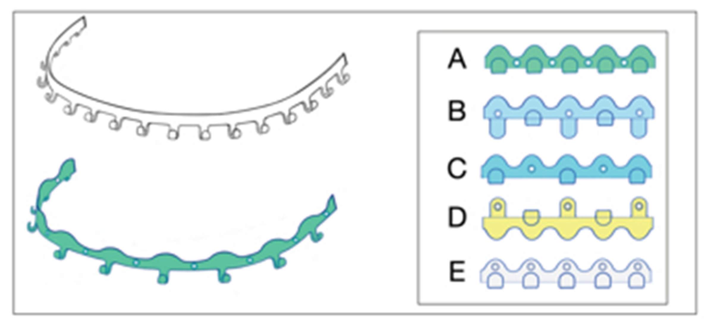
Figure 2.
Figure 2 A Legend. Clinical case example - Stryker SMARTLock Hybrid MMF System (regular size) in situ in a right condylar base fracture of the mandible. The arch bars are not shortened; several support legs (‘lugs’) have been bent along the length of their vertical axis to superimpose the screw receiving holes over the interradicular spaces; all holes except from the right lower 2nd molar are filled with bone screws; the screws are lined up below the mucogingival junction in the upper jaw; in the mandible the vestibules get shallow along the posterior bucco-alveolar sulcus, so these screws are placed in the mobile mucosa; in the anterior vestibulum the screws are located low to reach down into the opening interradicular spaces; with such deep placement the tooth equators cannot be attained. Preinjury occlusion with a lateral crossbite on the left is reestablished and maintained with anterior criss-cross elastic loop intermaxillary fixation. Note the kinking at the base of several bent supporting legs (‘lugs’). Figure 2 B Legend: Previous case cont’d. Immediate postoperative panoramic x-ray after placement of SMARTLock arch bars. Miniplate fixation of right condylar base fracture (ORIF). Interradicular position of all arch bar retaining screws. In the upper right quadrant 2 screws projecting over maxillary sinus. Eyelet of supporting leg (‘lug’) over right lower 2nd molar empty. Source/Origin of Figure 2 A and B: Photograph collection – C.P. Cornelius.
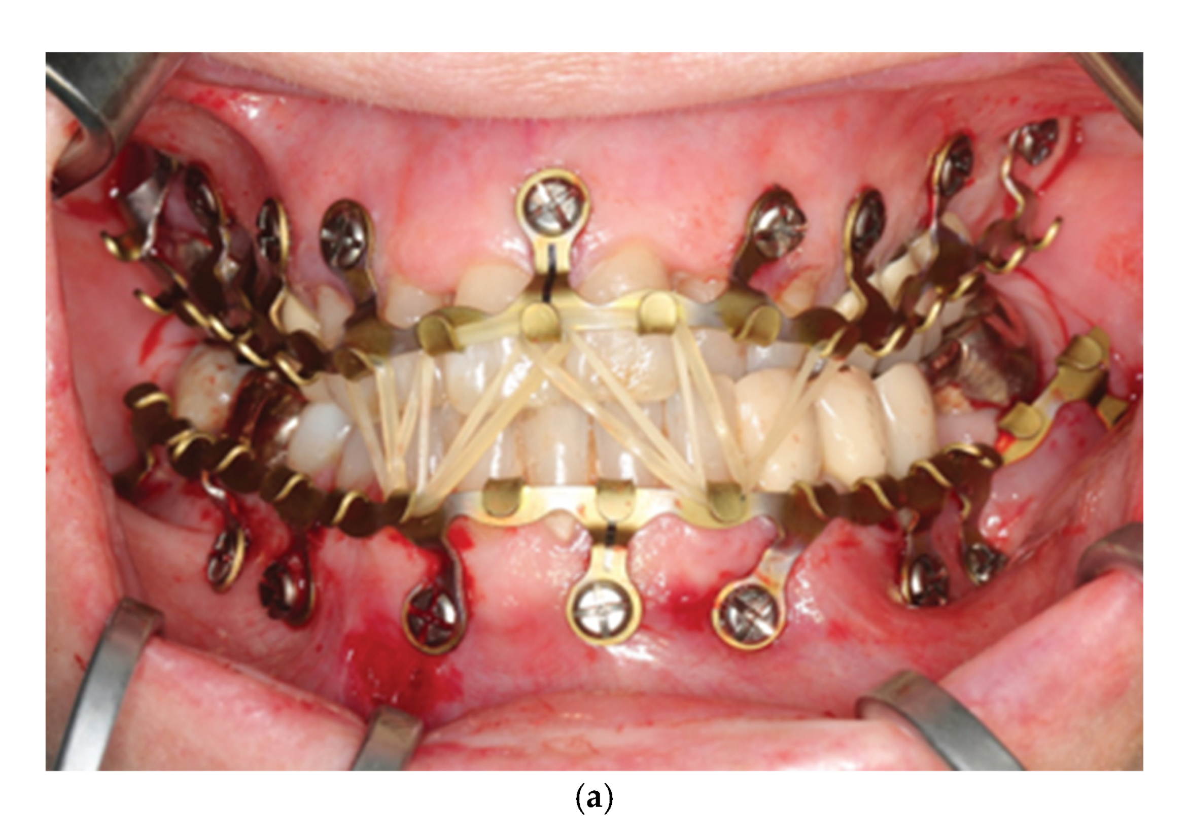
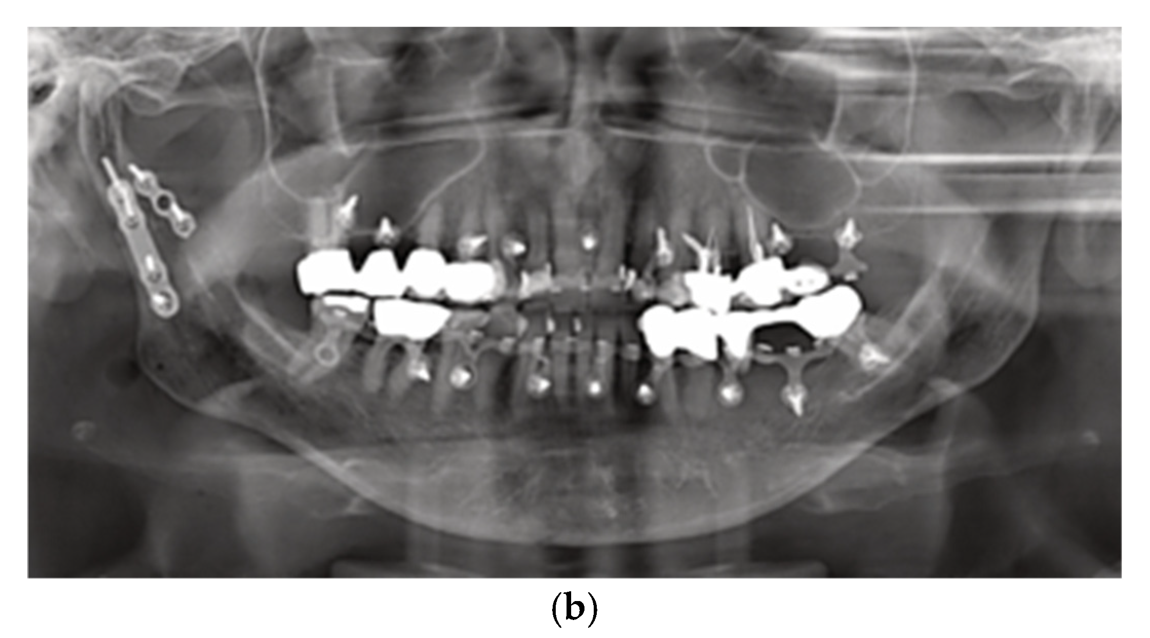
Figure 3.
Arrangement of OmniMax arch bars (plates) for application on the mandible and maxillae together with self-drilling locking screws. The plates are preformed by in-plane bending into slight curves. The screws are placed for fixation in the anterolateral transition and the posterior portion of the jaws. At best no more than two slots in sequence are left empty.
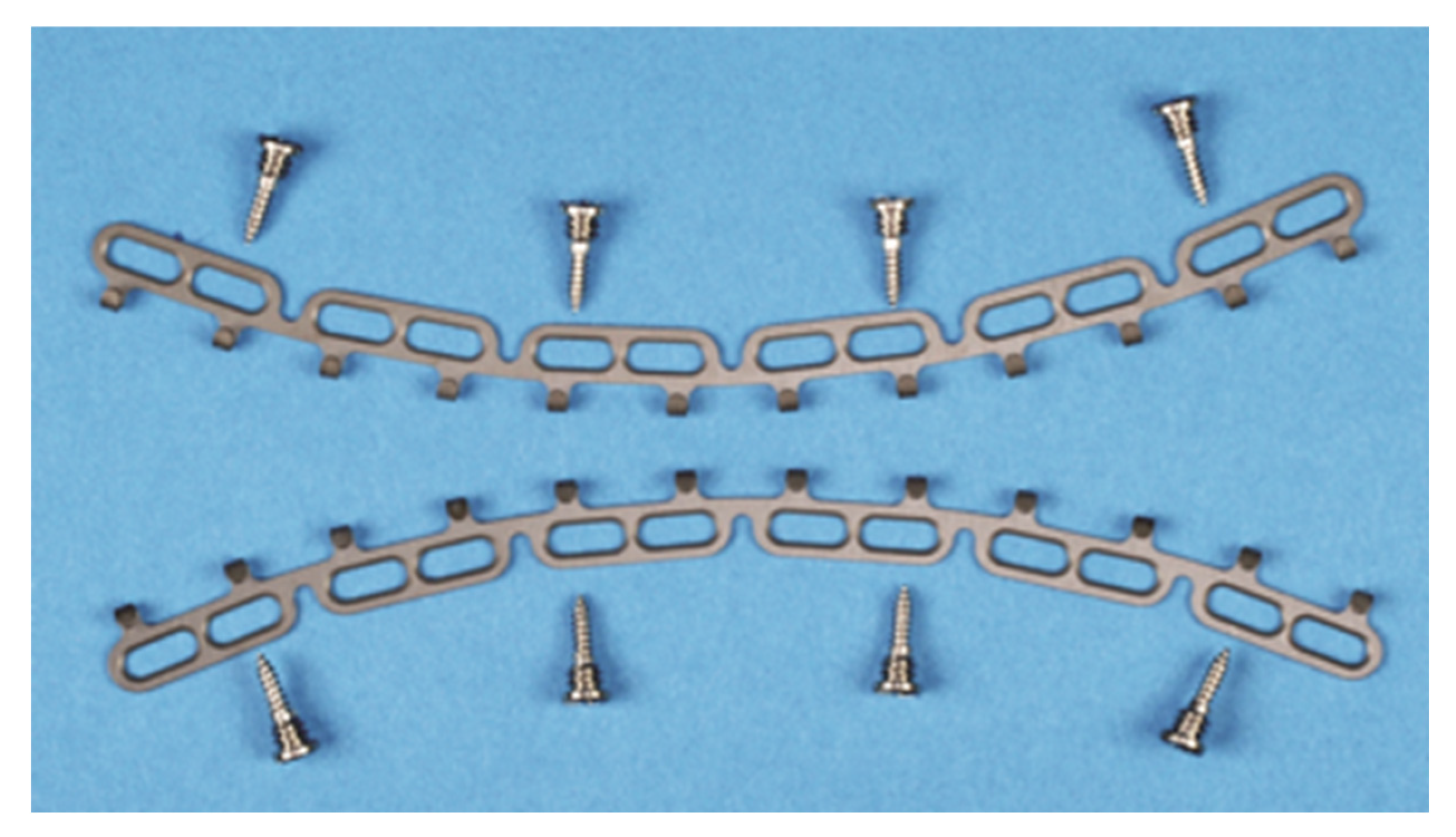
Figure 4.
Figure 4 A Legend: Clinical case example – Zimmer Biomet OmniMax MMF System in situ after a left condylar base fracture of the mandible. The lengths of the arch bars has been adjusted to encompass the dental arch from premolars to premolars. Multiple elastic loops for intermaxillary fixation interconnecting hooks and – exceptionally on protruding screw heads on the posterior left side. Of Note: The plate standoff mechanism has not been properly utilized for the posterior screws on the left, allowing the use of an elastic loop around these screws – not really intended for this purpose. The vertical placement of the devices is not ideal. Figure 4 B Legend: Previous case cont’d. Postoperative panoramic x-ray after placement of OmniMax arch bars. Miniplate fixation of left condylar base fracture (ORIF). All arch bar retaining screws are in interradicular positions. Source/Origin of Figure 3, Figure 4 A and Figure 4 B: Photograph collection – C.P. Cornelius.
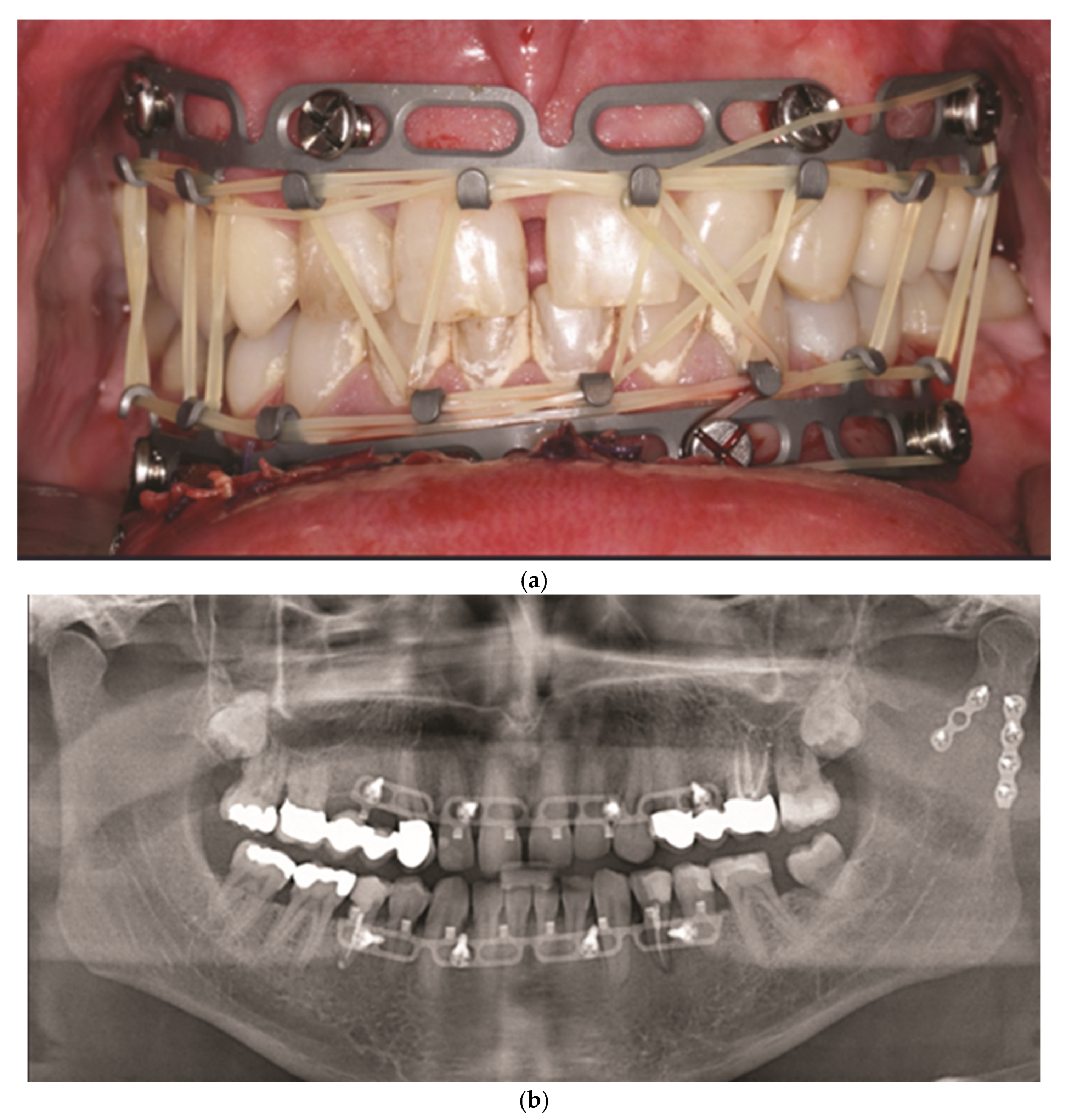
Figure 5.
Figure 5 A Legend: Clinical case example – intraoperative view of Zimmer Biomet OmniMax MMF devices divided into 4 segments for treatment of a triple mandibular fracture – bilateral condylar base and symphyseal midline. A dental splint (Titanium Trauma Splint, Medartis, Basel Switzerland) resin bonded (acid etching technique) to the outer surfaces of the teeth of the anterior maxillary arch supports the repositioned medial upper incisors. The two maxillary segments represent the shortest possible plate variant consisting of a single mounting tab containing two slot apertures. 2.0 four-hole miniplate visible in open anterior vestibulum approach. Of note: The standoff mechanism has been implemented for all screws – annular screw grooves fully seated in the slots. Figure 5 B Legend: Previous case cont’d. Postoperative panoramic x-ray after placement of OmniMax arch bars, ORIF – via transoral vestibular and preauricular transparotid approaches. Miniplate fixation of the condylar base fractures. Four-hole superior border (tension band) miniplate fixation in combination with a six-hole 2.4 inferior border plate The arch bar retaining screws appear inserted correctly in the interradicular spaces. Source/Origin of Figure 5 A and Figure 5 B: Photograph collection – C.P. Cornelius.

Figure 6.
Figure 6 A: Full arch assembly of L1 MMF arch bar / slider plates and intermaxillary wire ligatures – model – right lateral view. The maxillary bar sections above the incisors and premolars as well as the mandibular bar sections below the lower lateral incisors are void of tabs and gaps (‘teeth’); the angulation of the lateral slider plates and montage under tension maintains the purposed interdigitation between their slots and the arch bar rack. Note: suboptimal asymmetrical vertical placement of lower lateral arch bar sections subsequent to in plane bending alongside the free gingival margins and tooth necks (periodontally unfavorable). Source/origin of Figure 6 A: Courtesy of KLS Martin, Tuttlingen, Germany. Legend to Figure 6 B: Full arch assembly of L1 MMF arch bar / slider plates and intermaxillary wire ligatures – model - frontal view. Angulation of slider plates in upper incisor / canine regions; apart from a midline slider plate the lower incisor and canine region are spared from slider plates accounting for the high risk of tooth root injuries due to narrow interradicular spaces. Legend to Figure 6 C: Full arch assembly of L1 MMF arch bar / slider plates and intermaxillary wire ligatures – model – left lateral view. The slider plate below the lower canine is not properly engaged in the mating bar rack resulting from a too parallel montage – a flaw – in long-term yielding to forces and potentially hazarding stability. Source/origin of Figure 6 A, 6 B, 6 C: L1 MMF System provided by courtesy of KLS Martin, Tuttlingen, Germany – Model montage by C.P. Cornelius.
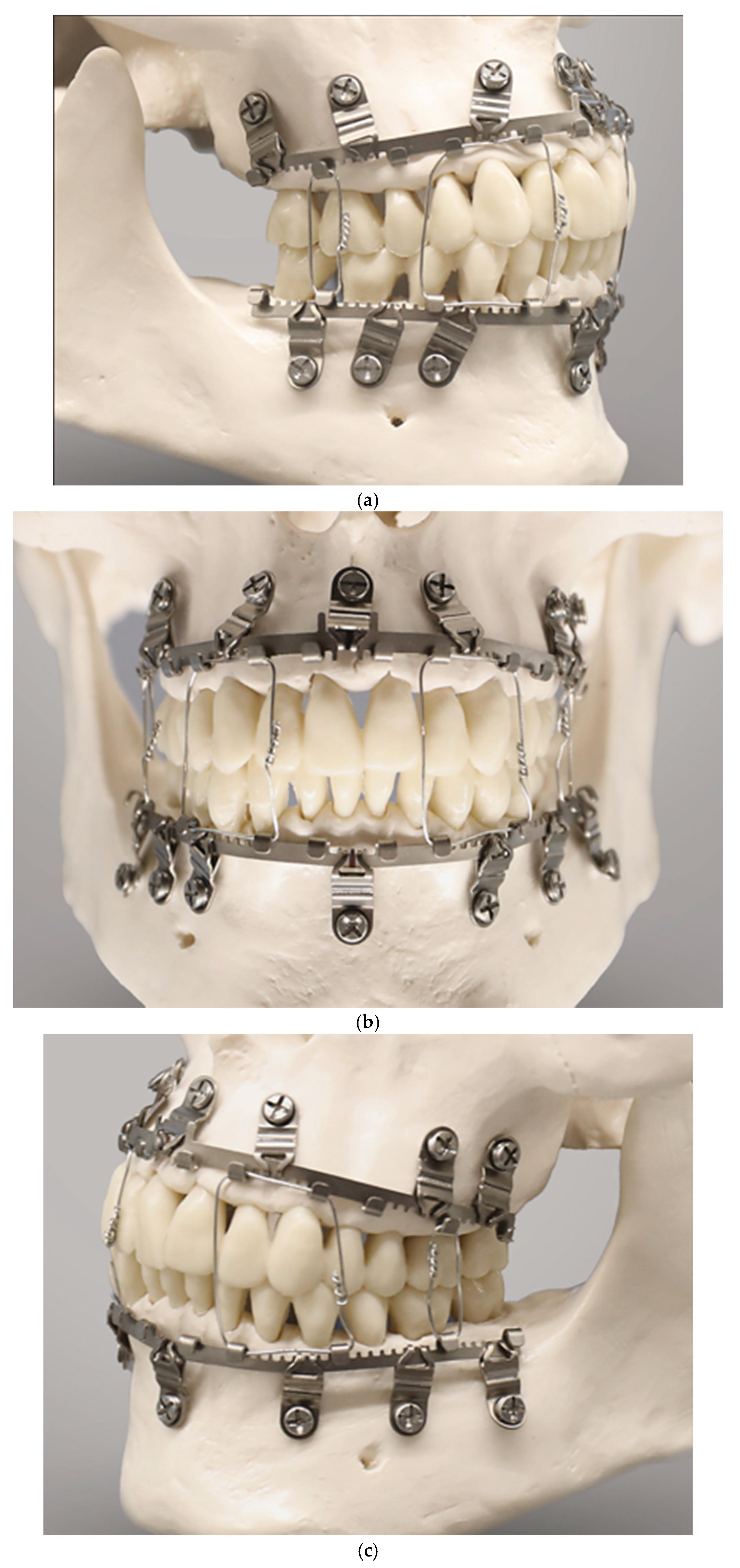
Figure 7.
Slider plate snapped in the trident midline halt of the central arch bar section– the shield at the end of the coupling portion abuts the front of the main body like a clip. Interior leeway space between and beyond the extension legs of the coupling portion (blue). (Inset top left) Slider plate unfolded to display its three components without overlapping: coupling portion with hour-glass slot design (light grey), main body (dark grey), screw receiving hole portion (rouge). (Inset top right) Transverse cross-sections of mounting plates snapped on arch bars oriented inversely for the mandible and maxillae. Room to move the mounting plates during coupling/removal maneuvers is highly limited antero-posteriorly but open vertically. Source/Origin of Figure 7: Modified from 2nd version for the embodiment in Patent No. US 10,470,806 B2 –12 November 2019 [15]. Schematic drawing – C.P. Cornelius.
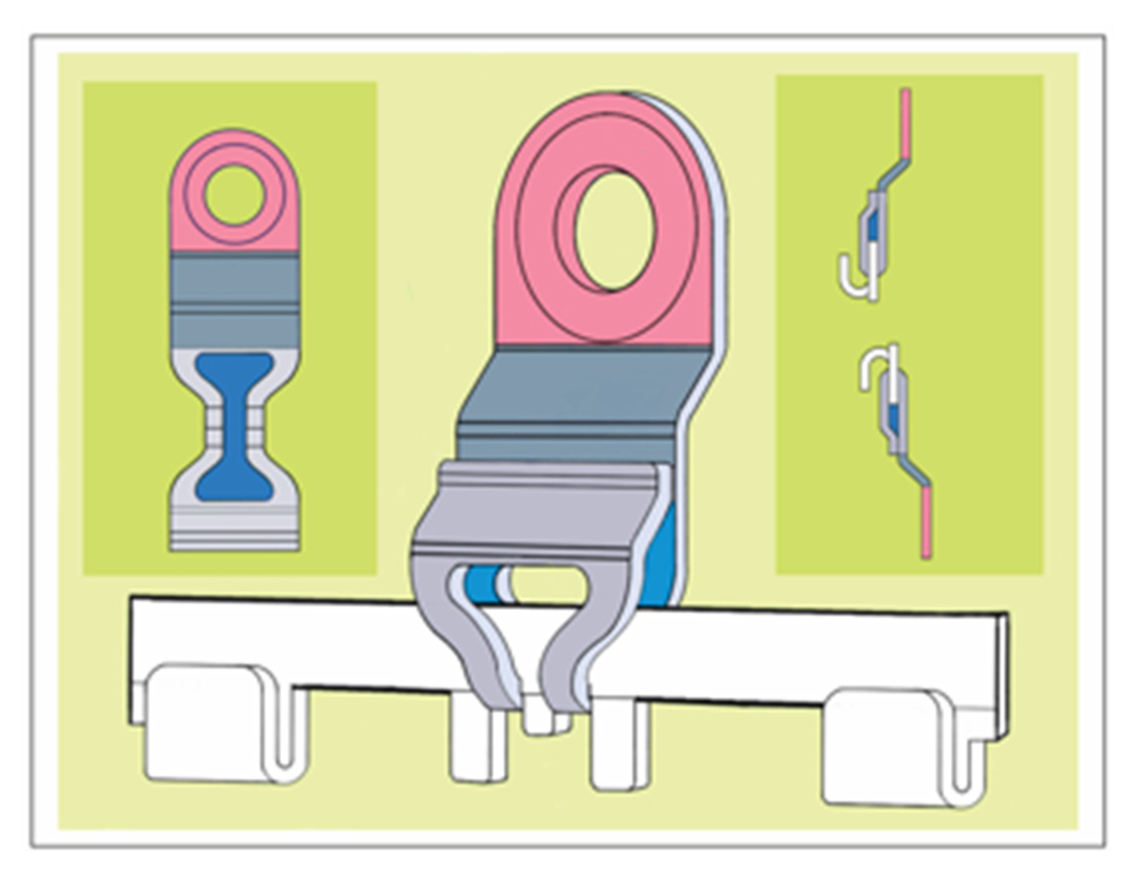
Figure 8.
Schemes of a SMARTLock arch bar - oriented and conformed in curvature for maxillary installation, (top left) SMARTLock hybrid bar embodiment – (top right) Superimposition with Erich type arch bar– note: hook lengths are extended vertically, (bottom left) Superimposition with conventional Erich arch bar, (bottom right) SMARTLock hybrid bar – cutaway illustration subdividing the platform bar and the lugs according to the ‘Erich with lugs’. Source/origin of Figure 8: Schematic Drawing – C.P. Cornelius.
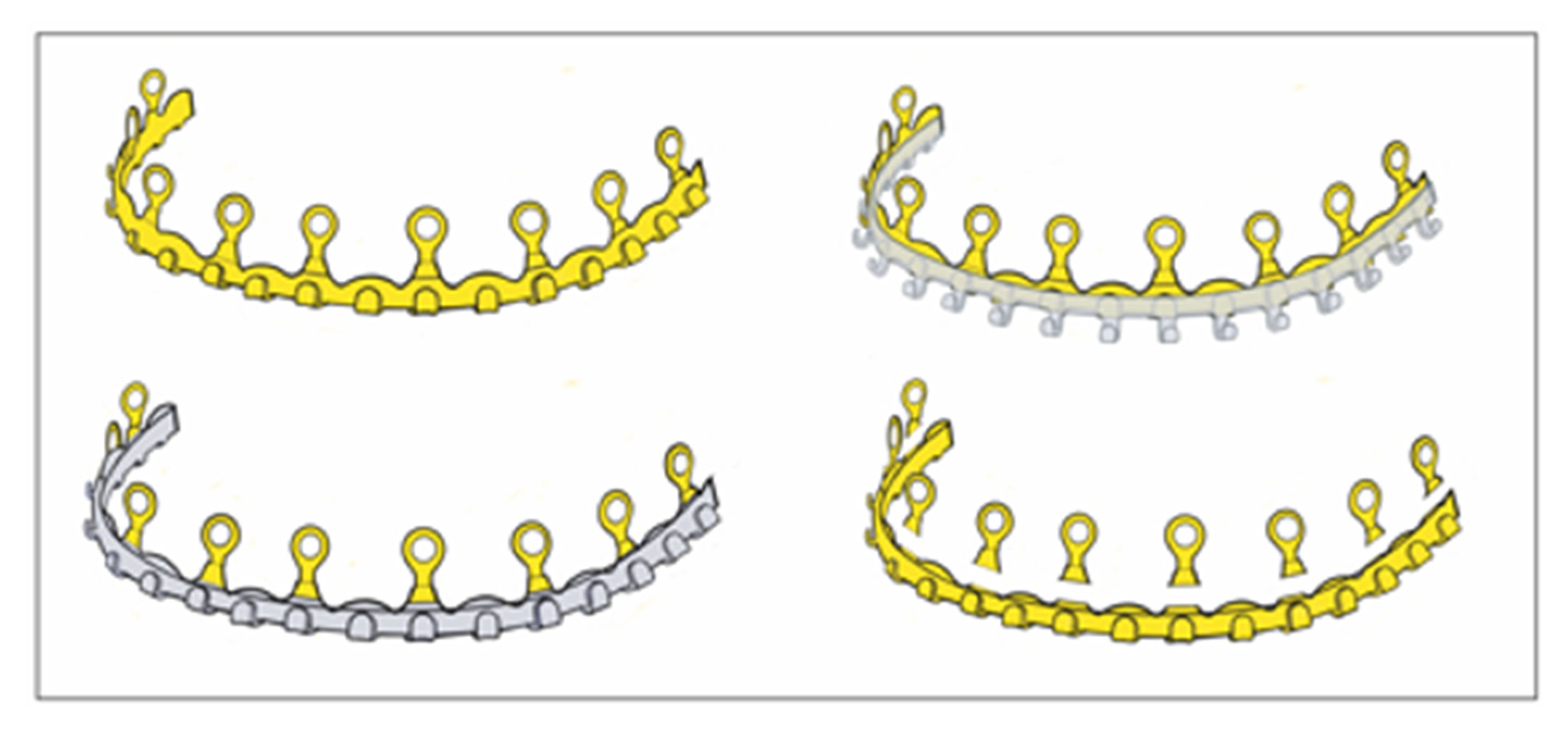
Figure 9.
SMARTLock lug /ring opening – Maneuverability (left) Single lug on a short bar segment – frontal view, (middle) Single lug, footing and attached bar – lateral profile/cross section. The vertical height of the lug, i.e., the radius or length between the center of the screw hole and mid of the footing (green arrows) and the material properties (thickness, rigidity, hardness, elasticity, elongation at rupture, etc.) predetermine the extent of movements in the frontal plane – precondition: static position of the bar. The radius length can be modified with the angulation of the footing plate. Thus a crescent surface area gets into reach of the screw receiving hole. Color coding: footing portion with buckling (dark grey), screw receiving hole portion (rouge), crescentic surface area (light grey) (inset - right) Synoptic scheme: target board with cross hairs and arrows demonstrating possible lug/eyelet movements to locate the screw receiving (bone anchor) hole into a safe interradicular zone: vertical translation, rotation around longitudinal z-axis, anteroposterior (longitudinal/sagittal) translation, minimal rotation around vertical y-axis. Source/origin of Figure 9: Schematic Drawing – C.P. Cornelius.
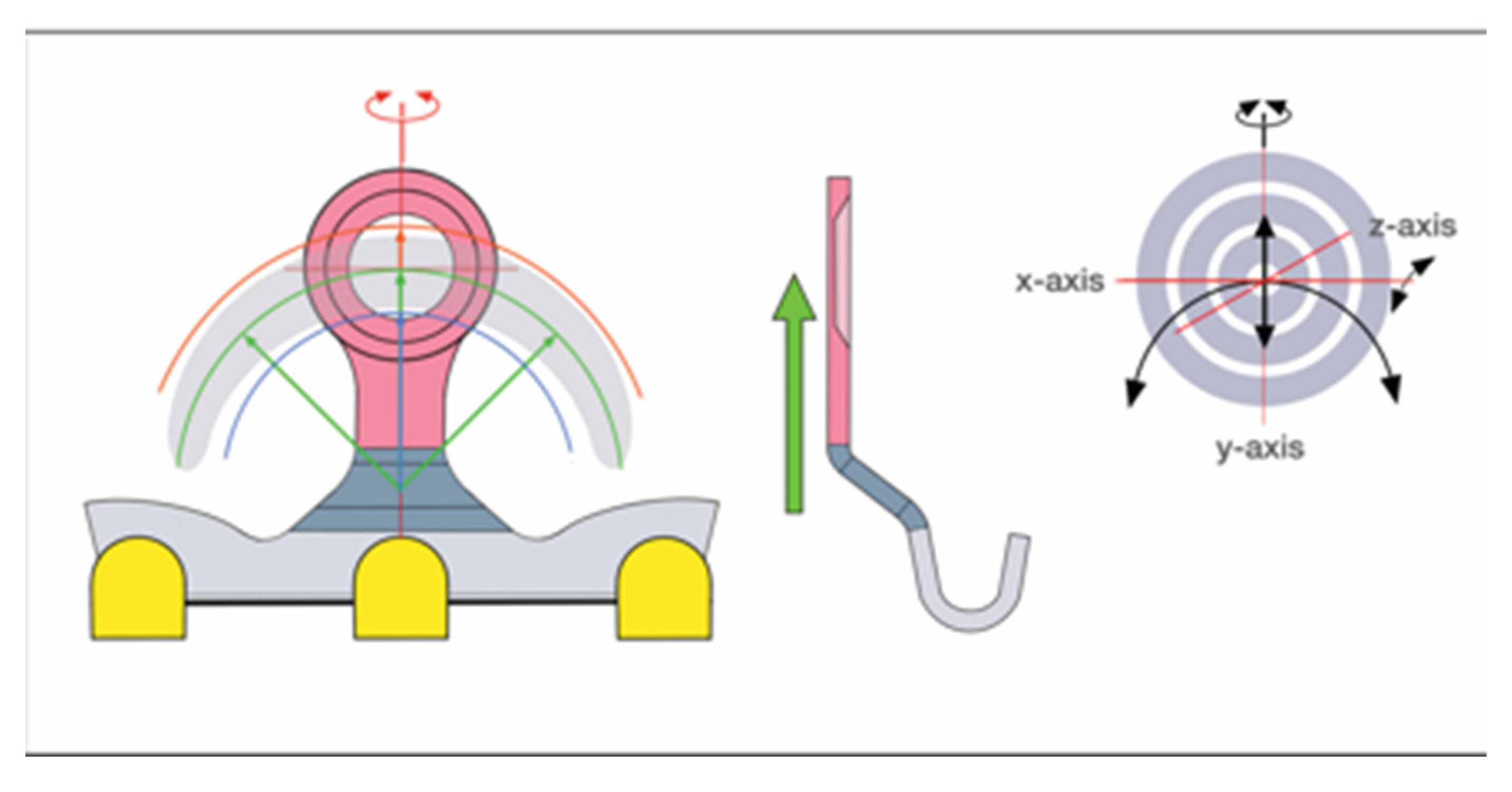
Figure 11.
Schemes of the OmniMax arch bar - (top left) Single bar segment - frontal view, both slots loaded with screws (center and bottom left) bar segment as part of a row, only one slot receives a screw for fixation into an interradicular space. (top right) Stylized 3 bar segments in a row with 2 pivoting junctions in between. The segments can be hinged along all segments in three spatial axes. (center right) A rotational movement around any of the axes - clockwise around the z-axis in this example – takes the next (third) segment along into the same direction. (bottom right) Readjustment of the third segment by a “counter”– clockwise rotation. Color coding: left-right sliding options within a slot (green arrows ), screw receiving slot portions (rouge), pivoting junctions (light blue). (inset - center far right) Synoptic scheme: target board with crosshairs demonstrating possible movements inside the slots to locate a safe zone for a screw insertion: transverse/horizontal translation along the x-axis. Source/origin of Figure 11: Schematic Drawing – C.P. Cornelius.
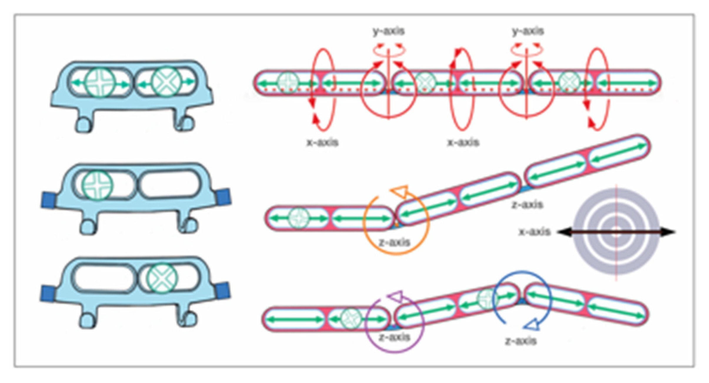
Figure 14.
Matrix Wave System embodiment (‘Plate’) - oriented and conformed in curvature for maxillary application – stylized schemes according to the MWP embodiment. (Patents No.: US 9,820,77 B2 – 21 November 2017 [46] and US 10,130,404 B2 – 20 November 2018 [48]) (left) MWP - oriented and conformed in curvature for maxillary application with the bone receiving (bone anchor) holes between crests (on top). (right) MWP superimposing an interrupted conventional Erich arch bar. The MWP abandons the band-like Erich arch bar configuration in favor of a periodic sinus wave; in contrast to the serpentine MWP a continuous band structure is capable to embrace the dental arch rigidly and this is frequently put forward as ‘tension band’ function. Source/origin of Figure 14: Schematic Drawing – C.P. Cornelius.
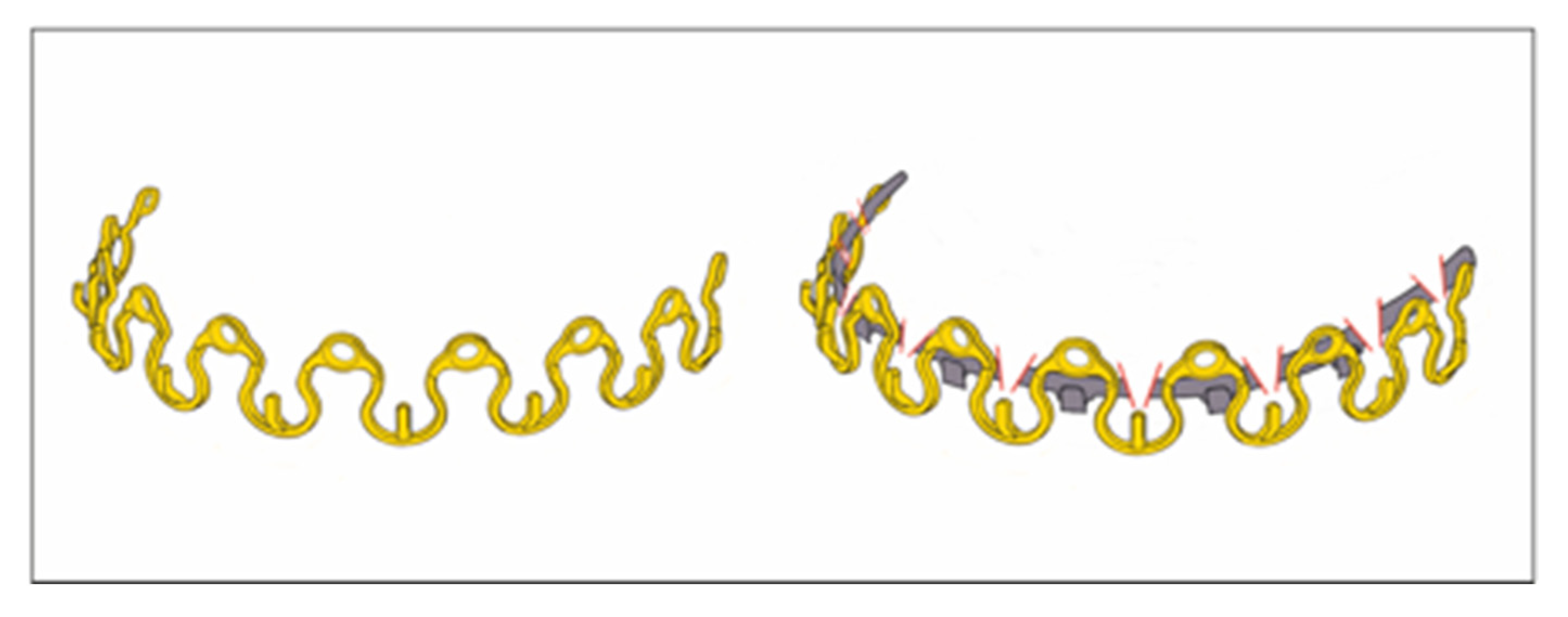
Figure 15.
Stylized scheme according to the MWP embodiment (Patents No.: US 9,820,77 B2 – 21 November 2017 [46] and US 10,130,404 B2 – 20 November 2018 [48]. (top left) one wavelength (λ)/ Omega MWP segment – can be tailored for omnidirectional placement of screw receiving holes and/or cleat (bottom left) stretching (blue double arrow) or squeezing (maroon inverted double arrows) in the Omega MWP segment exemplifies just a way to alter its winding , i.e., vertical height in relation to width in one single plane. (top center) two wavelength MWP partition to outline the potential movements of the central screw receiving hole plateau/flatbed panel (rouge) in all six degrees of freedom – rotational axes are indicated (bottom center) - indication of 3-dimensional translational motions; for instance - squeezing of the medial limbs (maroon arrows) increases the vertical height of the plateau with succedent transformation of the wave pattern. (inset - right) Synoptic scheme: target board with crosshairs demonstrating the potential movements of the mounting plates/screw receiving holes in six degrees of freedom to target a safe zone for a screw insertion. Source/origin of Figure 15: Schematic Drawing – C.P. Cornelius.
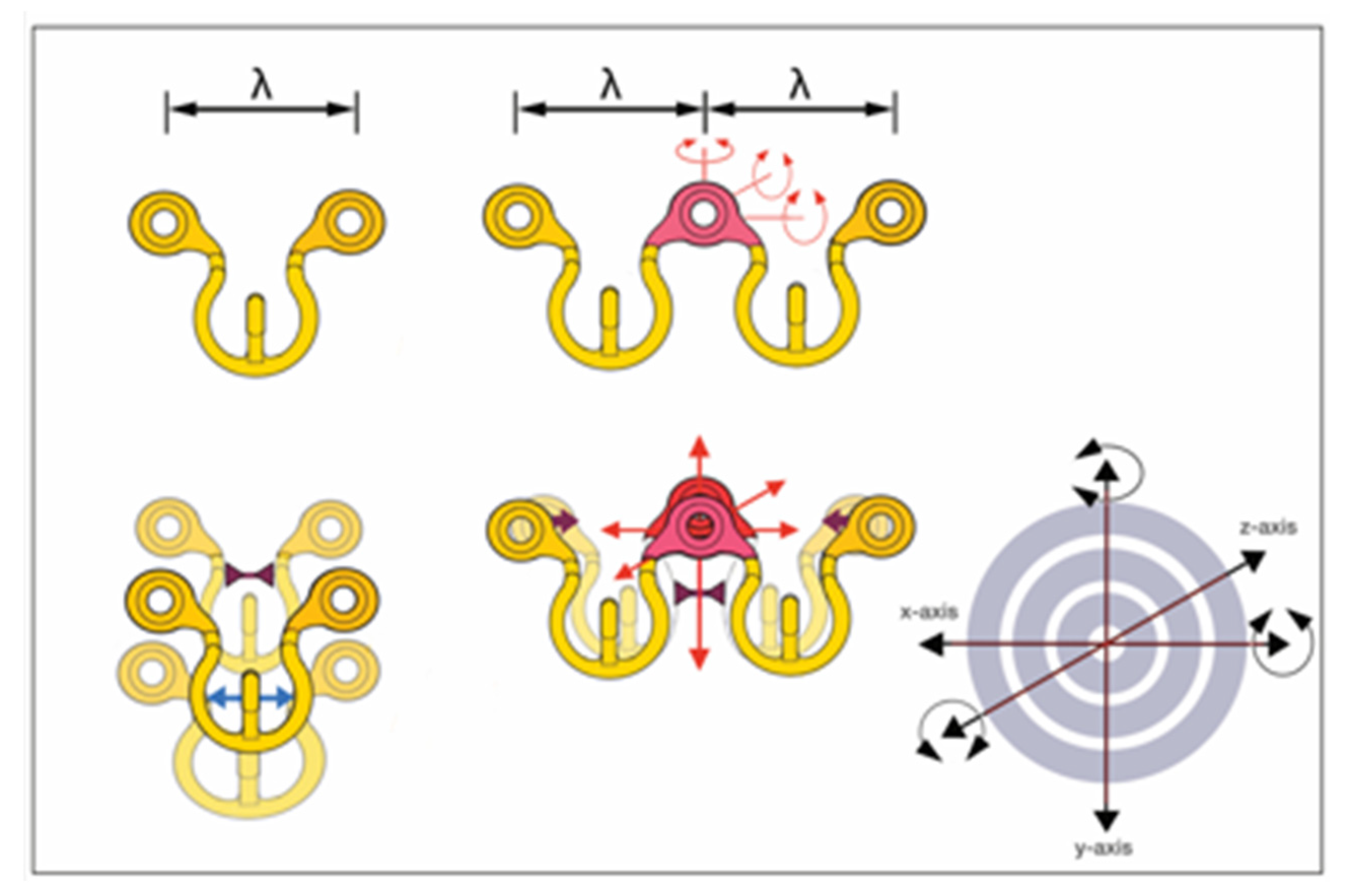
Figure 16.
Locking Screws of the League of commercial MMF Devices – frontal views at the same scale. (from left to right): Stryker SMARTLock – Stryker (gold); OmniMax – Zimmer Biomet, (silver) ; L1 MMF – KLS Martin (silver); Matrix Wave – Depuy-Synthes (gold). Double arrows indicate: Bone insertion threads (green); Locking heads / stop drums (red); groove /recess underneath screw heads (blue). The bone insertion threads begin below a neck or transgingival free part. [for more technical characteristics see text] Source/origin of Figure 16: Schematic Drawing – C.P. Cornelius.
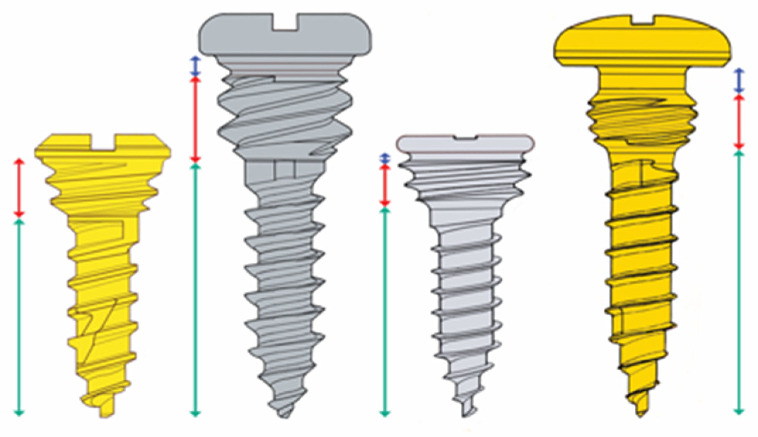
Figure 17.
Matrix Wave System full arch MMF set up – primary intermaxillary fixation with elastic loops across the cleats (hooks /tangs) next to the occlusal plane. Supplementary large span interarch fixation via the prominent heads of the bone fixation screws. (left) quadrangular wire cerclage cornered by the heads of two pairs of vis-a-vis screws to reinforce the elastic loop intermaxillary fixation. (right) longitudinal-oval and triangular wire cerclages around two or three opposing screw heads, cleat-to-screw elastic loop connections. Possible further connection variants (not shown) – screw-to-screw elastic loop, cleat-to-cleat wire cerclage, two screws-to-cleat and vice versa. Source/origin of Figure 17: Photograph collection – C.P. Cornelius.
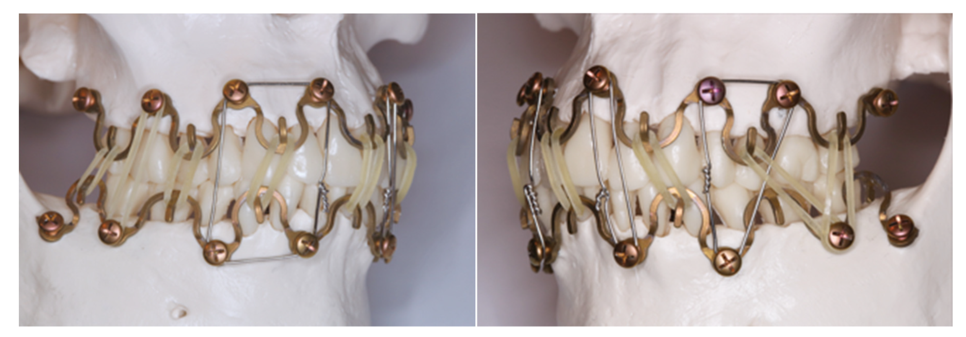

Table 1.
Self-made / Modified Hybrid Erich Arch Bars – Summary of Clinical Studies. Table 1 Legend: Patient age ≥ 18 years in all studies; Ø = not specified / no information; Hybrid = Modified Erich Arch Bar (EAB); [OHI-S] = Oral Hygiene Index-Simplified (Greene and Vermillion 1964) [12];[TGP-I] = Turesky-Gilmore (Glickman) Plaque-Index (1970) [13] (Modification of Quigley-Hein. Index - 1962) [14]; [Table 1 is attached as an Excel File: Self-made Hybrid Arch Bars_Table_1_Part II.xlsx].
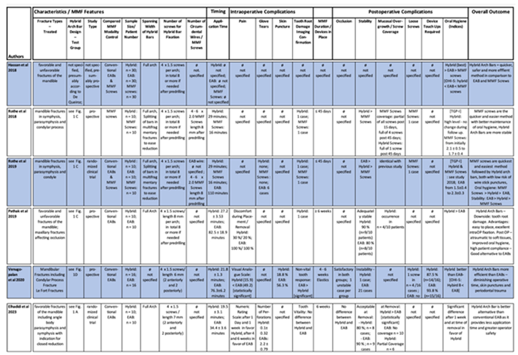 |
Table 2.
SMARTLock Hybrid MMF System - Summary of Clinical Studies. Table 2 Legend: Patient age ≥ 18 years in all studies; Ø = not specified / no information; Hybrid = SMARTLock hybrid MMF System; [OHI-S] = Oral Hygiene Index-Simplified (Greene and Vermillion 1964); Three studies used stainless steel facsimiles / replicas of the titanium SMARTLock hybrid MMF System bone fixation with conventional screws – Rani et al. 2018, Sankar et al. 2023, Burman et al. 2023. [Table 2 is attached as an Excel File: League_of_Commercial_Hybrid_MMF_Devices_Table_2_Part II.xlsx].
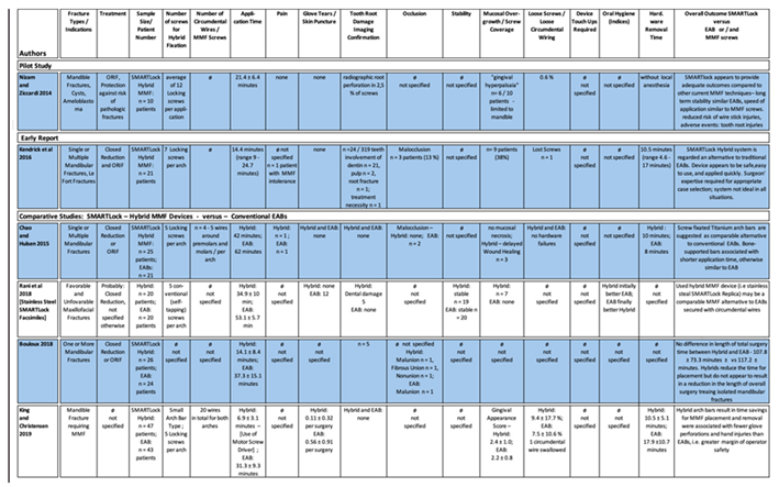 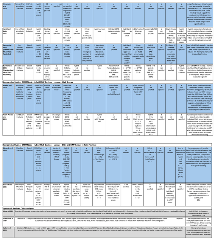
|
Table 3.
Synopsis – Placement sites for Orthodontic Miniscrews and likewise for Locking Screws for Hybrid Arch Bars and Commercial Hybrid MMF Systems.
Table 3.
Synopsis – Placement sites for Orthodontic Miniscrews and likewise for Locking Screws for Hybrid Arch Bars and Commercial Hybrid MMF Systems.
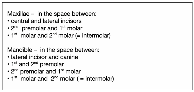 |
Disclaimer/Publisher’s Note: The statements, opinions and data contained in all publications are solely those of the individual author(s) and contributor(s) and not of MDPI and/or the editor(s). MDPI and/or the editor(s) disclaim responsibility for any injury to people or property resulting from any ideas, methods, instructions or products referred to in the content. |
© 2025 by the authors. Licensee MDPI, Basel, Switzerland. This article is an open access article distributed under the terms and conditions of the Creative Commons Attribution (CC BY) license (http://creativecommons.org/licenses/by/4.0/).
Copyright: This open access article is published under a Creative Commons CC BY 4.0 license, which permit the free download, distribution, and reuse, provided that the author and preprint are cited in any reuse.


