Submitted:
26 February 2025
Posted:
26 February 2025
You are already at the latest version
Abstract
Edge and fog computing have enhanced traditional client-server computing. However, the emergence of Smart Cities is rapidly changing this outlook because they must provide essential services, including ubiquitous communications, intelligent transport systems, advanced medical platforms, and urban infrastructure management. This demands a secure and resilient low-latency, high-bandwidth environment to provide a sustainable Quality of Service to applications and services. To meet this challenge, a new computing and networking ecosystem must be developed in which servers are managed and run from the edge of the Internet rather than from the centre as they currently are. This ecosystem is called the Intelligent Edge Environment (IEE) and is seen as the next major evolutionary step for the Internet. This journal article explores the development of this new paradigm. Firstly, the Reference Model for the IEE is detailed. Then, new mechanisms needed to build an Implementation Model of the IEE are discussed. The paper then examines the design of a new Internet to meet the challenges of developing Smart Cities.
Keywords:
Intelligent Edge Environment
; Reference and Implementation Frameworks
; Capabilities
; IPv6
; Smart Cities
1. Introduction
Mobile Edge Computing (MEC) has been successfully used to enable a better Quality of Service (QoS) to applications by offloading server processing to elements at the network edge. This has been enhanced by the deployment of new communication systems such as 5G and vehicular networks which help provide low latency connections. However, in order to develop applications and services for Smart Cities, a sustained low latency, high bandwidth ecosystem must be developed. One of the ways that this can be done is to manage and run services from the edge of the Internet by default rather than from the centre of the Internet as they current are. This represents a new computing and networking environment and is called the Intelligent Edge Environment or IEE which will replace the current Internet. This paper looks at the development of the IEE; it first looks at the IEE Reference Framework. It then examines the mechanisms needed to implement the IEE which will allow services to be managed from the edge of the Internet. Finally, the paper outlines a new networking paradigm which will be used to build a more flexible and intelligent Internet.
The contributions of this paper are as follows:
- A new Implementation Framework for the IEE is presented
- Mechanisms need to build the Implementation Framework are detailed
- A new Networking structure is discussed
- A new Internet system is shown.s
- Work needed to build a full blown prototype is discussed.
The rest of the paper is structured as follows: In Section 2, the IEE is discussed while Section 3 looks at the Related Work. Section 4 details the Implementation Framework while Section 5 highlights the work done on building the IEE. Section 6 explores the New Internet and Section 7 concludes the paper.
2. The IEE Reference Model
As shown in Figure 1, the IEE is composed of these 7 layers: Heterogeneous Networking Layer, Data Management Layer, the High-Performance Edge Cloud Systems, Service Management Framework, Microservices Layer, Application Framework Layer, and Application Layer. The details of the IEE have been explored in [1].
2.1. Intelligent Edge Environment Layers
The layers of the IEE are shown in Figure 2 and are briefly described below:
- Layer 1: Heterogeneous Networking Layer (HNL): This layer provides connections using various wireless technologies such as 4G, 5G, WiFi, and Cellular.
- Layer 2: Data Management Layer (DML): This layer plays a crucial role in handling vast amounts of data generated by edge devices such as Connected and Autonomous Vehicles (CAVs) and uses many structures such as blocks, files, databases, and ML algorithms to manage data.
- Layer 3: High-Performance Edge Cloud Systems (HPECS): This layer supports various cloud architectures and cloud types, including private, public, hybrid, and community clouds (AWS, Hadoop, etc.) using Virtual Machines (VMs) including VMware and Citrix ecosystems as well as video streaming, augmented and virtual reality, and autonomous systems.
- Layer 4: Service Management Framework (SMF): This layer manages services and servers within the system. It offers mobile service support by migrating and replicating services using various migration techniques such as Docker (containerization), KVM (virtualization), and Unikernels (specialized single-purpose virtual machines).
- Layer 5: Microservices Layer (MSL): This layer supports microservices and is responsible for independently deployable services. These services should be fast and small in order to be easily migrated.
- Layer 6: Application Framework Layer (AFL): This layer uses the Microservices Layer below to provide Applications Frameworks (AFs) to build applications for different environments such as Mobile Communications, Vehicular Networking, and IoT Smart Grids.
- Layer 7: Application Layer (AL): This layer allows applications that have been built using the Application Framework Layer to be installed on the system and made available to users. Through this layer, users get applications that use all the resources of the IEE.
For Smart Cities, the IEE may be viewed as a digital Ring Road which consists of Core Endpoints as shown in Figure 3
3. Related Work
There is an extensive topic and so we have divided it in several sections:
3.1. The Success and Failings of the Internet
The current Internet, which is based on the IP Suite of protocols including IP, TCP, UDP, ICMP, etc., has been very successful. However, this set of protocols have not evolved to provide the secure, sustainable, low latency, high bandwidth Internet needed to support Smart Cities. There are several reasons for this situation. Firstly, the Internet was invented as a communication system based on packet datagram technology, we have been trying to add key concepts of mobility, Quality of Service and security on top of communication systems which has been challenging. IPv6 [2], the newer version of IP, was developed to address some of these concerns, but the move to IPv6 has not been successful. However, IPv6 allowed the exploration of identifying network nodes using a Location/ID split paradigm [3]. Several groups experimented with this idea and showed that it was effective. To complicate matters further, we have seen the rolling out of middleboxes such as NAT Servers and Firewalls which have made it more difficult for the Internet to evolve, because it destroyed the end-to-end argument without replacing it with another network structure.
Software Defined Networking (SDN) [4], [5] which separates the Control and Data Forwarding planes, was supposed to add flexibility to network control and management. For the Southbound interface, the Openflow protocol has been specified. However, these benefits are yet to be fully realised with SDN because of a lack of standardised northbound interfaces. A new northbound interface called the Network Control Management Protocol (NMCP) [6] was explored to allow dynamic setup and fast handover of connections.
3.2. Mobile Edge Computing
Mobile Edge Computing has been used to do server processing at the edge of the network. The authors in [7] showed a comprehensive survey of Mobile Edge Computing (MEC), which brings computing and storage closer to mobile devices to support low-latency, computation-intensive applications in 5G and IoT environments. The efforts clearly showed that MEC could improve latency and energy efficiency. Service providers are, therefore, more willing to put resources at the edge of the Network. Two recent projects in this area are EDGELESS [8] and CODECO [9]. EDGELESS is an ongoing EU project focused on developing a secure edge-cloud platform that can dynamically adjust to ensure a high Quality of Service (QoS) for applications, while the CODECO project aims to enhance the container orchestration platform, Kubernetes, with a cognitive edge-cloud management framework designed to support real-time industrial applications. While these projects are interesting, the IEE is about building a new computing and networking ecosystem.
3.3. New Networking
In terms of networking, we are seeing the wide-scale deployment of 5G systems. Another significant development is the deployment of fibre in cities. This has dramatically reduced the latency and increased the bandwidth to urban homes. New vehicular technology such as 6G and IEEE 802.11bd, is also being deployed to support Connected and Autonomous Vehicles (CAVs). Support for CAVs with very strict communication requirements to support important applications is now a key requirement of Smart Cities.
3.4. IoT Devices for Smart Cities
Smart Cities will need billions of IoT devices. These devices need to be secured. However, since these are simple devices, end-to-end encryption using PKI cannot be used. Hence more networking support will be needed to make these systems secure.
3.5. Research Gap
The research discussed above clearly points to the need for an Intelligent Edge Environment which will allow services to be run and managed from the edge of the network. However, we also need to develop a new Internet architecture which is based on the edge computing paradigm.
4. Designing Implementation Framework
The IEE Reference Framework details the functions and their hierarchy in order to realise the IEE. However, an Implementation Framework is needed to detail the mechanisms and techniques needed to build a prototype of the IEE. There are key goals which need to be an integral part of this framework.
4.1. Design Approach
Firstly, the system needs to be secure. The system must be able to implement confidentiality, integrity and availability (CIA) which are the tenets of cyber-security. Secondly, the system must provide a low latency, high bandwidth environment to enable time-critical applications and services to be deployed. Finally, the system needs to support a number of different Application Frameworks including mobile communications, transport systems, and IoT smart grids. Using these goals, an Implementation Framework was designed as shown in Figure 4.
The system is built on traditional Operating Systems such as Linux, Android, etc. The rest of the layers of the Framework are discussed below:
4.2. Object Management System (OMS)
. The system revolves around objects as the basic system structure. Everything is represented as an object, including users, services, applications, files, and databases, etc. An object should also have a name, a type and a subtype or variant. An object can be represented using 72 bits, with 64 bits using the EUI-64 format and 8 bits as the Netadmin field as shown in Figure fig5 and Figure 6. To support mobility, the EUI-64 is globally unique. The Netadmin field is described as follows:
The NetAdmin field is detailed as follows:
- The Scope field, or SF, is two bits long and is used to indicate the accessible range of incoming requests for this object. So the value (0,0) denotes that the object is only accesssible by other objects on the same machine or the same LAN. The value,(0,1), represents site scope in which the node is only accessible by other objects at the same site. The value (1,0) is used to signal that only machines on the same domain are allowed to access the server. A value of (1,1) denotes that the object can be globally accessed.
- S or static bit is used to indicate that the device is stationary. This allows the networking infrastructure to cache routes to these devices such as servers.
- The M bit indicates whether the Node Id represents a multicast group. This may be used to deliver data to multiple machines on the same network, or to support global multicast mechanisms.
- The Interface number field, or INF, is used to indicate which interface is being used for a particular connection and is 4 bits long. A value of 0 means that the packet may be delivered to any one of the available interfaces on a device, while a value of 0xF is used as a broadcast mechanism and so the packet will be delivered to all the available interfaces simultaneously. An INF value of 0x1 tends to signify the primary interface for the device.
4.3. The Capability System
Intelligent Edge Environment (IEE) capabilities are crucial for secure and efficient access control. By utilizing role-based capabilities and advanced addressing systems like IPv6, the IEE can ensure robust access management and resource allocation while maintaining high levels of security and integrity. The IEE is a dynamic environment where security challenges are significantly higher than those in traditional computing environments. It was therefore decided that AAA should be based on the subject or user rather than the object. This approach is more scalable and suitable for modern, complex environments. Consequently, capabilities are used to provide AAA for the IEE, ensuring that security and access control mechanisms are effective and adaptable to the unique demands of edge computing [10].
4.3.1. Capabilities Structure
In the Intelligent Edge Environment (IEE), capabilities must be carefully managed and protected to prevent unauthorized creation or modification, and they should be easily revocable. The format of the capability-based system is shown in Figure 7, and its structure is explained below:
- Type Field (8 bits): This field specifies the type of object capability being used, such as users, digital assets, facilities, etc.
- SYS Field (4 bits): This field helps manage capabilities. The four bits within the SYS field are explained below.
- Property Field (12 bits): This field defines the properties of the object associated with the capability. It relates to the properties or functions of the object that the capability refers to.
- Object ID (72 bits): This field uniquely identifies the object in the system. It includes a EUI-64 identification field to identify the object and an 8-bit netadmin field to manage the object on a network.
- Random Bit Field (16 bits): This field provides unforgeability and helps uniquely identify the object. This field is generated after the type field, SYS field, property field, and Object ID field are created. When proxy certificates are created, a new random field is generated. This field also allows for easy revocation of capabilities by simply changing the random field and recomputing the hash field, hence revoking previous versions.
- Hash Field (16 bits): This field detects the tampering of capabilities. When a capability is created, the type field, SYS field, property field, and Object ID field are first generated, followed by the random bit field. These fields are then used to generate a SHA-1 hash, which is placed in the Hash Field of the capability.
As shown in Figure 6, the SYS field consists of the following bits:
- Private or P bit: Restricts the list of people holding the capability. With a public capability, only the capability for the object must be presented, allowing anyone to hold it without needing the identification of the subject, the person holding the capability. With a private capability, both the object’s capability and the subject’s capability must be presented to ensure the subject has the right to invoke the object.
- System or S bit: Indicates whether the object involved was created by the system or by an application or user. A system capability cannot be modified or deleted by users or applications.
- Master or M bit: Indicates that the capability was created by a Certificate Authority (CA). The master capability is usually created when the object is created. If this bit is not set, it means this is a proxy capability. Proxy capabilities are derived from master capabilities and cannot be derived from other proxy capabilities.
- Change or C bit: Indicates whether this capability can be changed. If this bit is set, proxy capabilities can be derived from the master capability. If this bit is not set, the capability cannot be modified, and proxy capabilities cannot be generated.
By adhering to these principles, Intelligent Edge Environments can maintain a high level of security and efficiency, ensuring that resources are managed effectively and that unauthorized access is prevented.
4.4. Secure Comms Layer
This layer is used to provide secure, low latency and high bandwidth between objects. This could be implemented using the following components.
4.4.1. Low-latency Transport Protocol
Low latency transport protocols (LLTPs) provide the latency required for time-critical applications and services. Because of the development of multiprocessors, which allow a lot of CPU cycles to be available in user space, LLTPs now can run in user-space.
4.4.2. Authentication and Encryption
To ensure totally secure communications, end-to-end authentication and encryption, the IPSec framework [11] can be used to implement secure encryption and authentication. In this situation the Object_ID forms part of the IPv6 address.
4.4.3. Secure Transactions
Transactional Security allows secure information exchange between communicating parties. This is done via a strongly typed Remote Procedure Call called SRPC in which both the type of parameter being used in the arguments as well as the value of the parameter are specified to allow correct interaction between the communicating parties. Servers can therefore ensure that valid arguments are being passed by clients while clients can check that the server has returned meaningful results.
4.5. Interactive Services Layer
This layer allows the interaction between the IEE system, services and applications. It is composed of the following entities which are then explained in detail below.
- Service Management Framework (SMF) This component manages service interaction. The SMF is used to register, request and migrate services in support of mobile users and applications throughout the IEE. Service Providers must register their services with the SMF. Once this is done, servers that implement the service are also added. When clients request a service, the SMF returns the security capabilities needed to access the service as well as a server that implements the service. If the client is mobile, the client can request that the service be migrated closer to the user if it is experiencing QoS problems with the service. The details of a prototype SMF are explored in [12].
- Data This component allows applications and services to access data from various systems including files, databases, or data blocks. The system will support different types of file formats as well as several database types.
- Streaming The system allows data to be streamed between two entities, including functions such as recording and playback. Different video formats will be supported and different Content Delivery Networks (CDNs) will be available.
- Events Management System (EMS) This is used to support events within system. An event is posted to a port where an event handler deals with the event. Event types and event handlers must be registered with the EMS. Events are handled in a flexible manner. The caller may choose to block until the event is dealt with. In addition, applications may asked to be notified if an event occurs.
- Traps, Triggers and Tripwires This allows the system to deal with critical situations such as resource shortages or network issues. These situations must be handled by the calling thread; it must not be blocked and its priority is increased to the highest priority while handling the situation.
- Monitor Support To support jobs that may require complex interaction between processes, support for monitors are provided. Monitors allow callers to wait within the monitor. The structure of a monitor is shown in Figure 9. Processes enter via the gate semaphore to wait on given events on the event-pending process queues. Only one process can be running in the monitor at any one time. When the process is finished, the process calls the exit function. This function will first check to see if there are any processes within the monitor which should be woken up. If not, it will signal the gate semaphore which will allow other processes to enter the monitor,
- GUI A basic Graphical User Interface Library is provided to allow window-based applications to be developed.
4.6. Application Framework layer
This layer allows Application Frameworks (AFs) to be built for different environments including mobile computing, vehicular networking and applications and smart IoT. These AFs make use of the Interactive Layer and provide Software Development Kits (SDKs) that allow applications for that particular environment to be built.
4.7. Application Layer
This layer runs that applications developed by using the Application Framework Layer.
5. Work Done on Building the IEE
Several parts of the framework detailed above have been studied through the doctoral research of students from the Middlesex University (MDX) VANET Research Group. The Intelligent Service migration using a proactive approach explored in [13] while secure service migration was investigated in [14] and detailed in [15]. The Capability System and the SRPC system was developed by [16] . In addition, a new user-space transport protocol called the Simple Lightweight Tranasport Protocol (SLTP) [17] has been developed and attempts are now being to fully deploy it. SLTP also provides mechanisms against replay and man-in-the-middle attacks.
6. The New Internet
The development of Smart Cities will entail the fusion of communication, transport, and IoT Infrastructures into a cohesive scalable model. The extensive deployment of fiber-optic networks, combined with the adoption of low-latency 5G technology, strengthens this infrastructure. This advancement enables seamless data exchange and facilitates real-time analytics. A key architecture for heterogeneous networking [18] is the Y comm Framework as shown in Figure 10, which provides a view of the Internet based on a Core network and a Peripheral network. This approach also provides explicit support for security, mobility, and QoS as shown in the relevant layers.
This approach as shown in Figure 11 represents a network architecture that connects Peripheral Wireless Networks (such as 2G, 3G, LTE, etc.) to a Core network through Core Endpoints in the Access Networks. Peripheral Wireless Networks are access networks that provide connectivity to end-users through various wireless technologies, and the Core network is the central part of the network that ensures Quality of Service (QoS) and secure connections. It manages and routes data between different peripheral networks via the Core Endpoints in the Access Networks.
This network structure is used to provide a new network paradigm for the Internet. To resolve the Internet’s ossification, a clear network structure is necessary to allow packets to be routed and to give a more detailed picture of network traffic and operations. We now explore this using the network structure discussed above.
6.1. Network Entities List
First, the list of network entities are detailed below.
- An endpoint is a device that sends and receives data but does not route packets, such as laptops and smartphones used to access the internet. An endpoint must be globally identifiable. The 72-bit Object_ID is used to identify endpoints.
- A network is a group of connected devices that use network technology to communicate with each other, such as Wi-Fi. A router in every network helps direct Internet traffic.
- A site is a set of co-located networks or multiple networks in the same location. A Site Manager manages different networks and endpoints at a given site.
- A domain is a set of sites which work together as an autonomous system via a Domain manager that interacts with the Site managers in that domain.
- Core Endpoints connect the Peripheral and Core networks and are responsible for moving traffic over the Core Internet. Domains are connected to Core Endpoints. A Core Endpoint Manager controls a number of Core Endpoints. For example, a Smart City would be expected to a Core-Endpoint Manager.
How these entities work together to provide communication is shown in Figure 12. When an endpoint is turned on or moves into a new network, it must register with a Site Manager that gives the endpoint a Network/Host address. The Site Manager also registers the endpoint with the Domain Manager which will in turn register the endpoint with the Core-Endpoint Manager. So the joining endpoint will receive its Network/Host ID, its Domain/Site ID as well as the Core Endpoint to which it is connected.
6.2. Routing Information in the New Internet
The present Internet uses IP addresses and IP headers to route packets. In this new world, the structure of the new Routing packet is shown below in Table 1. Though this new header contains more information about the path to the endpoint, it should reduce the time taken to move packets around as it should be easy to cache connection information for well-known endpoints. The breakdown of the Routing header is given below:
- Dest/Source Endpoint: This is the Object_ID discussed in the previous sections.
- Dest/Source Network/Host: This is a 32-bit entity, similar to an IPv4 address. Like IPv4, this parameter can be divided into Class A, B, and C network addresses.
-
Dest/Source Domain/Site: This is a 32-bit entity that can have classes similar to IPv4:
- -
- Class A = 24 bits - domain with 4 million sites, e.g., An ISP
- -
- Class B = 16 bits - domain with 64K sites, e.g., Smart City
- -
- Class C = 8 bits - domain with 256 sites, e.g., Global Company
- -
- Class D = 4 bits - domain with 16 sites, e.g., A regional company
- -
- Class E = 2 bits - domain with 4 sites, e.g., City Brand
- -
- Class F = 1 bit - domain with 1 site, e.g., a Corner Store
- Dest/Source Core Endpoint: Represented by a 32-bit quantity such as an IPv4 address. Core Endpoints may be assigned from a unique set of global IPv4 addresses.
Thus, the new Routing Header consists of:
This represents 42 bytes of data which is quite reasonable for such a detailed header.
6.2.1. Setting up a Connection in the New Internet
A network association between two endpoints by the Routing header must be set up before data packets can be exchanged. This is done using a PATH_FINDER message. The Object_IDs for both the source and destination must be known. A PATH_FINDER request packet with the Object_IDs is sent to the Site Manager of the sending endpoint. The Site Manager will first check if the Dest Object_ID is on the same site. If so, it sets the Dest Network/Host ID and return the PATH_FINDER packet back to the Source Endpoint. If this is not the case, the PATH_FINDER packet is sent to the Domain Manager. The Domain Manager will first check if the Dest Object_ID is is in its domain. If so, it sets the Source Domain/Site and Dest Network/Host ID parameters and returns the PATH_FINDER packet to the Source Endpoint. If this is not the case, the PATH_FINDER packet is sent to the Core Manager. If the Core Manager detects that the Dest Object_ID is in the same Core-Endpoint, it returns the Dest Domain/Site as well as Dest Network/Host information to the Source Endpoint. If not, the Core Endpoint Manager will talk with other Core Managers to find out which Core-Manager knows about the Dest Object_ID. Once this is resolved all the information is returned to the Source Endpoint. The Routing header is used to send data packets to the destination endpoint. For security reasons, this is done using VPNs. So a VPN is set up between the source endpoint and Source Core Endpoint. Another VPN is set up between the Source Core Endpoint and Destination Core Endpoint. Finally, another VPN is set up between the Destination Core Endpoint and the Destination endpoint. So all connections in the New Internet will be secure by default.
6.3. Analysing Network Connections
Using this approach, it would be easy to have a much more detailed analysis of network connections. This would allow a more detailed traffic analysis because we will be able to describe connections in terms of their boundary crossing as shown below:
- Intra-network – This connection does not cross a network boundary
- Inter-network – This connection crosses a network boundary
- Intra-site – This connection does not cross a site-boundary
- Inter-site – This connection crosses a site-boundary
- Intra-domain – This connection is within a domain
- Inter-domain- This link crosses several domains.
- Intra-Core-Endpoint – This connection is within a Core-Endpoint
- Inter-Core-Endpoint – This is a connection between two Core-Endpoints
6.4. Benefits of the New Approach
This new approach has several benefits. First, using the suggested network structure would allow for the gathering of much more data about flows and connections, using the different network managers in the system.This data will allow the identification of strong and weak connections and should result in much better resource and network management, resulting in a substantial decrease in Operating Costs (OPEX) for Internet Prime Carriers and Service Providers.
Secondly, this approach will allow much more efficient domain pairing. Currently, domain pairing occurs through centrally managed linx exchanges. This approach will allow pairings to happen at the core endpoints, which will significant reduce the flows towards the centre of the Internet. In addition, there will be no need for things like NAT, which though useful, has complicated the networking space. Firewalls will not be needed as the PATH_FINDER mechanism as well as the Scope Field in the OBject_ID should be able handle possible network access violations.
Finally, the approach will allow the use of AI and ML at various levels of the architecture [19], resulting in the ability to apply new algorithms and mechanisms, enabling continual improvement.
7. Conclusions and Future Work
This paper looked at the design, development, and implementation of the Intelligent Edge Environment, in which servers are run and managed from the edge of the network. This should lead to a new computing and networking ecosystem, which will enable a more efficient and dynamic Internet. Work is continuing to build a full-scale implementation of the new platform. The initial prototype will be developed as an overlay network on the current Internet. The IEE will provide significant techniques and mechanisms that will be used in the development of Smart Cities.
Author Contributions
Introduction, Methodology, Design G.K. and G.M writing, review and editing G.K., J.C., and G.M. All authors have read and agreed to the published version of the manuscript.
References
- Gayathri, K; Glenford, M; Jon, C, Building an Intelligent Edge Environment to Provide Essential Services for Smart Cities. Proceedings of MobiArch ’23, Spain,02 October 2023; Pages 13 - 18. [CrossRef]
- Deering S and Hinden R: 2460 in RFC 2460 - Internet Protocol, Version 6 (IPv6) Specification. IETF, December 1998.
- Kunishi M, Ishiyama K, Uehara K, Esai H and Teraoka F: LINA: A New Approach to Mobility in Wide Area Networks. IEICE Trans, Commun., vol E84-B, No 8, August 2002.
- Open Networking Foundation: Software Defined Networking: The New Norm for Networks. April 2012.
- Duan Q: Network-as-a-Service in Software Defined Networks for end-to-end QoS provisioning, Orocessing of the 23rd Conference on Wirelexs and Optical Communication (WOCC). Newarj, NJ, USA, IEEE, 2014, pp. 1-5.
- G. Mapp, F. Sardis and J. Crowcroft, "Developing an implementation framework for the Future Internet using the Y-Comm architecture, SDN and NFV," 2016 IEEE NetSoft Conference and Workshops (NetSoft), Seoul, Korea (South), 2016, pp. 43-47. [CrossRef]
- Pavel, M; and Zdenek, B. Mobile edge computing: A survey on architecture and computational offloading. IEEE Communications Surveys Tutorials 19, 3 ([n.d.]), 1628–1656. [CrossRef]
- Edgeless:Cognitive edge-cloud with serverless computing Available online:. Available online: https://edgelessproject.eu/ (accessed on 18-July-2024).
- CODECO:A novel Edge-Cloud orchestration framework, focusing on data-compute-network. Available online: https://he-codeco.eu/ (accessed on 18-July-2024).
- Vithanwattana N; Karthick G; Mapp G; George C; Samuels A; Securing future healthcare environments in a post-COVID-19 world: moving from frameworks to prototypes. J Reliab Intell Environ. 2022;8(3):299-315. [CrossRef] [PubMed]
- Doraswamy N and Harkins: IPSec: The New Security Standard for Internet, Intranets and Virtual Private Networks. Prentice Hall Security Series. Prentice Hall 2003.
- Ramirez J, Ezenwigbo A, Karthick G, Trestian R and Mapp G: A new service management framework for vehicular networks. 23rd Conference on Innovation in Clouds, Internet and Networks Paris 2020.
- Ezenwigbo, A. Exploring Intelligent Service Migration in a highly mobile network. PhD Thesis Middlesex University December 2022.
- Karthick, G. Exploring a resource allocation security protocol for secure service migration in commercial cloud environments. PhD Thesis Middlesex University January 2023.
- Karthick, G. and Mapp G. Developing a Secure Service Ecosystem to Implement the Intelligent Edge Environment for Smart Cities. Future Internet 2024, 16, 317. [Google Scholar] [CrossRef]
- Vithanwattana, N. Securing mHealth - Investigating the development of a novel information security framework. PhD Thesis Middlesex University February 2023.
- Ezenwigbo A, Paranthaman V V, Trestian R, Mapp G, Sardis F: Exploring a new transport protocol for vehicular networks. 2018 Fifth International Conference on Internet of Things: Systems, Management294 and Security, IEEE 2018, pp 287-294.
- Glenford M, Fatema S, David C, Jon C, and Javier B. 2007. Y-Comm: a global architecture for heterogeneous networking. In Proceedings of the 3rd international conference on Wireless internet (WICON ’07). ICST (Institute for Computer Sciences, Social-Informatics and Telecommunications Engineering), Brussels, BEL, Article 22, 1–5.
- Sani L, Iacob A, Cao Z, Marino B, Gao Y, Paulik T, Zhao W, Shen W F, Alexsandrov P, Qiu X, Lane N D. The Future pf Large Language Model Pre-training is Federated. Available online: https://arxiv.org/abs/2405.10853 (accessed on 21 February 2025).
Figure 1.
Intelligent Edge Environment.
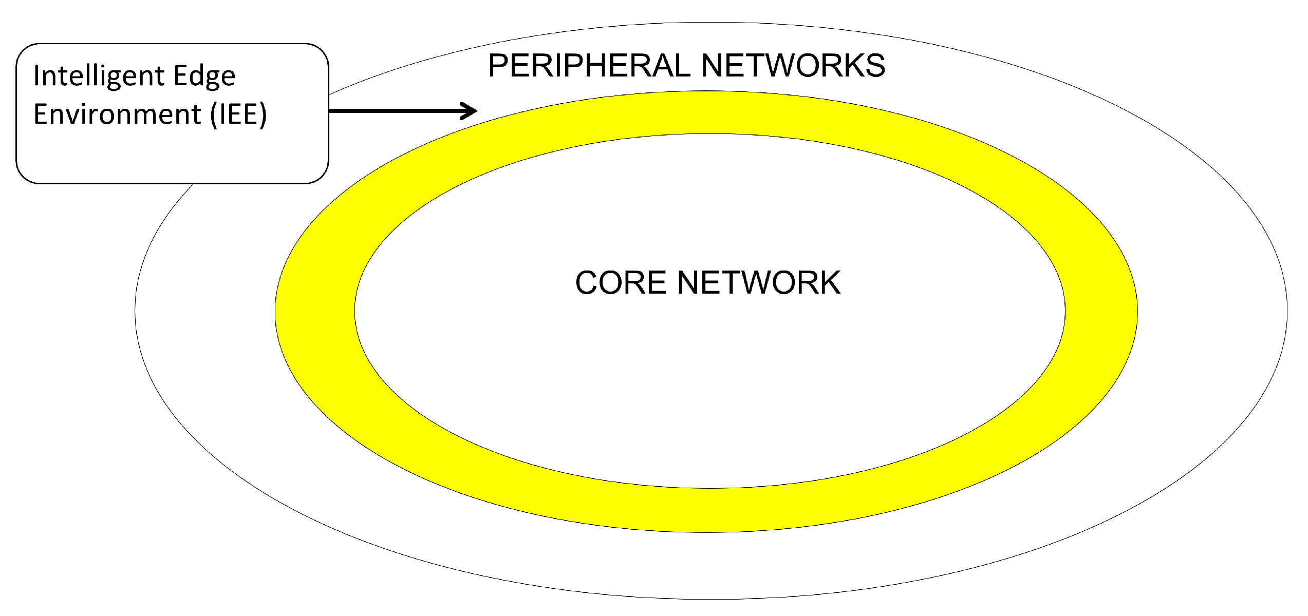
Figure 2.
Intelligent Edge Environment Layers.
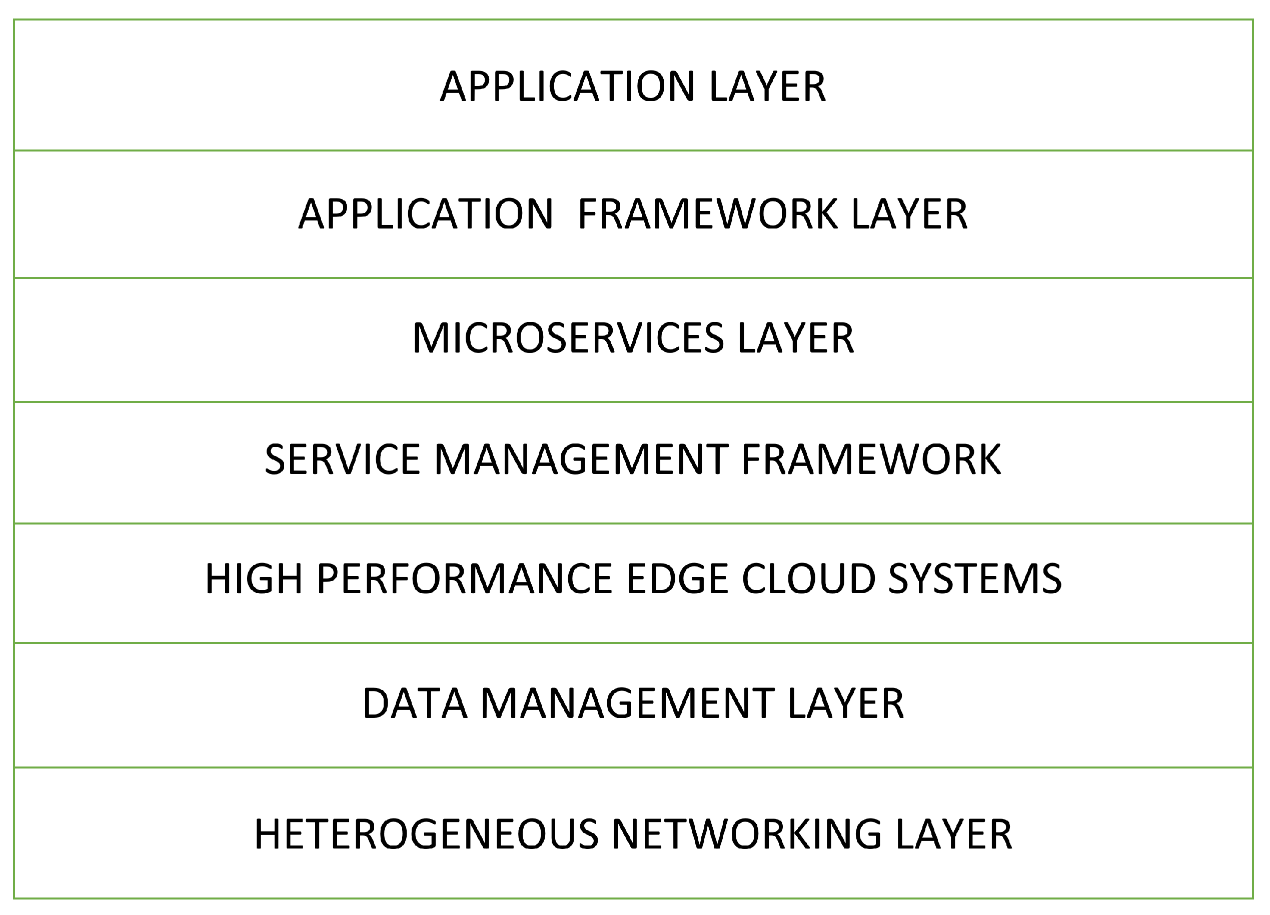
Figure 3.
IEE - Digital Ring.

Figure 4.
An Implement Framework for the IEE.
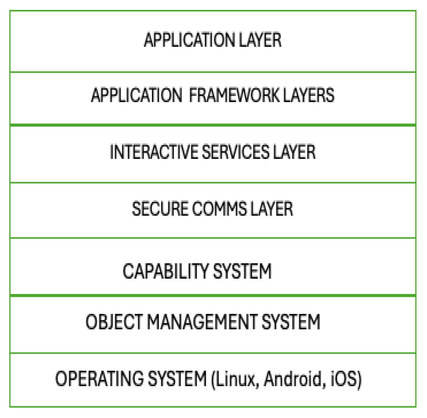
Figure 5.
72-bit OBJECT IDENTIFIER.

Figure 6.
NETADMIN.

Figure 7.
Capability Structure.

Figure 8.
Capability Structure - SYS FIELD.

Figure 9.
Monitor Structure.
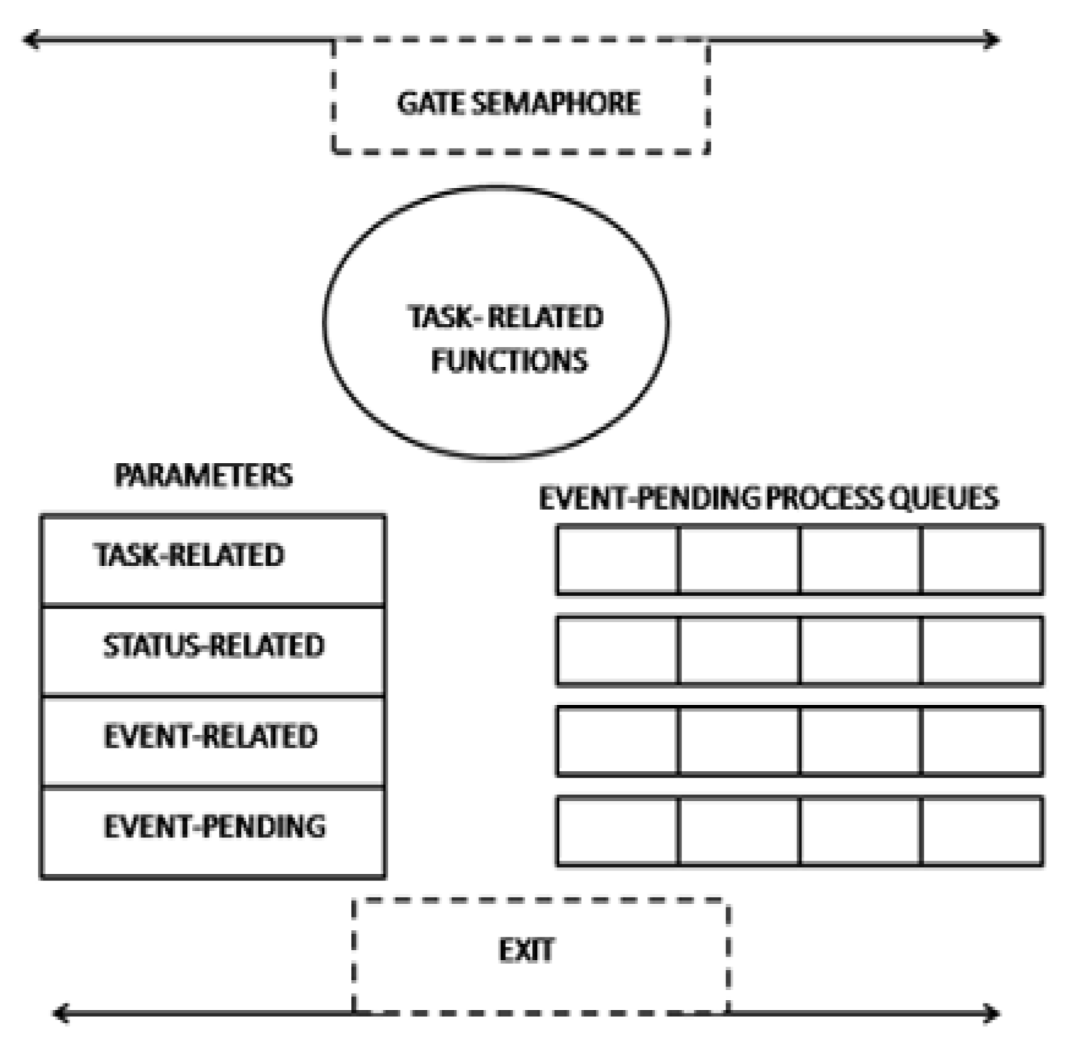
Figure 10.
Y-comm framework.
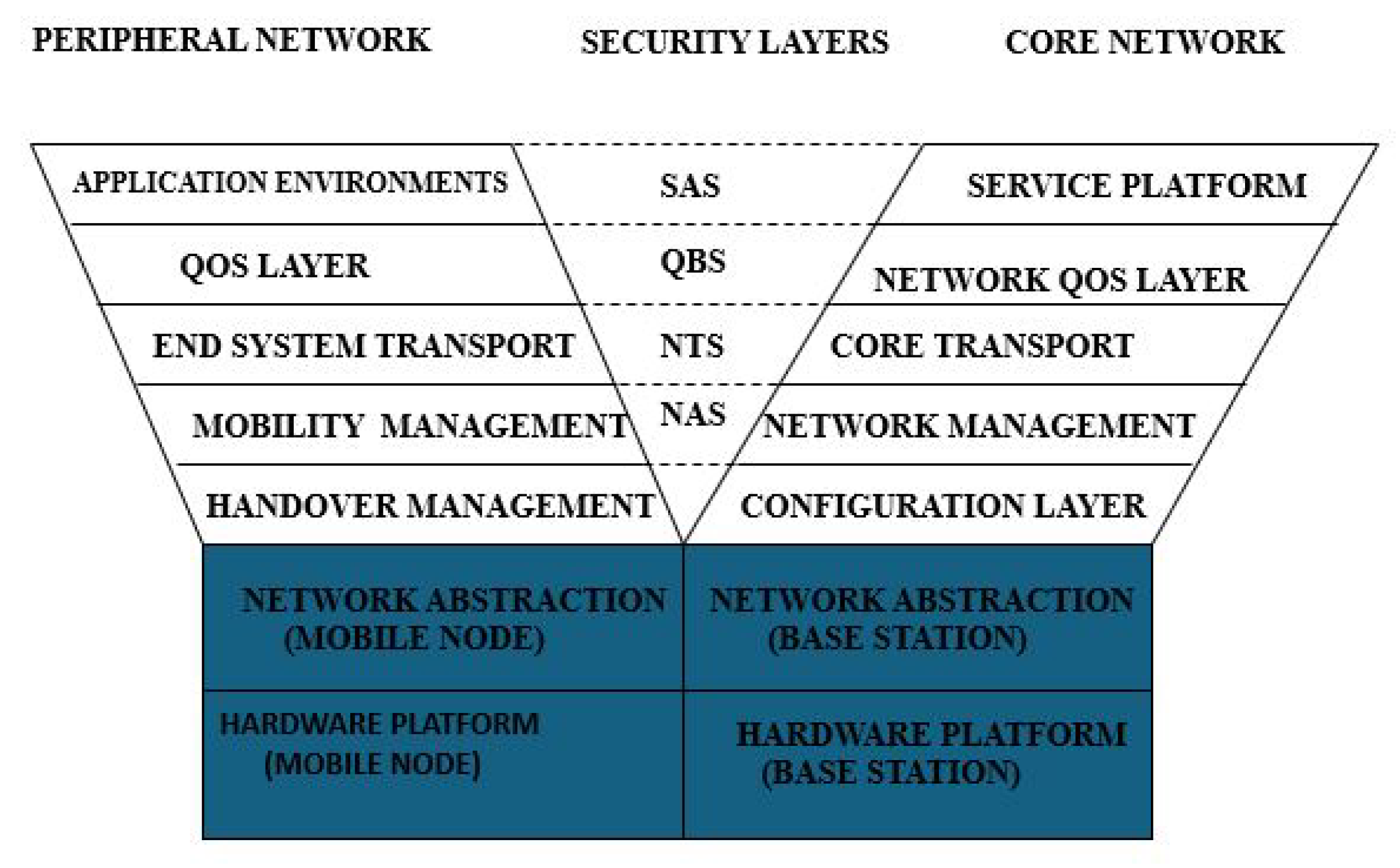
Figure 11.
Core Endpoints in the Access Networks.
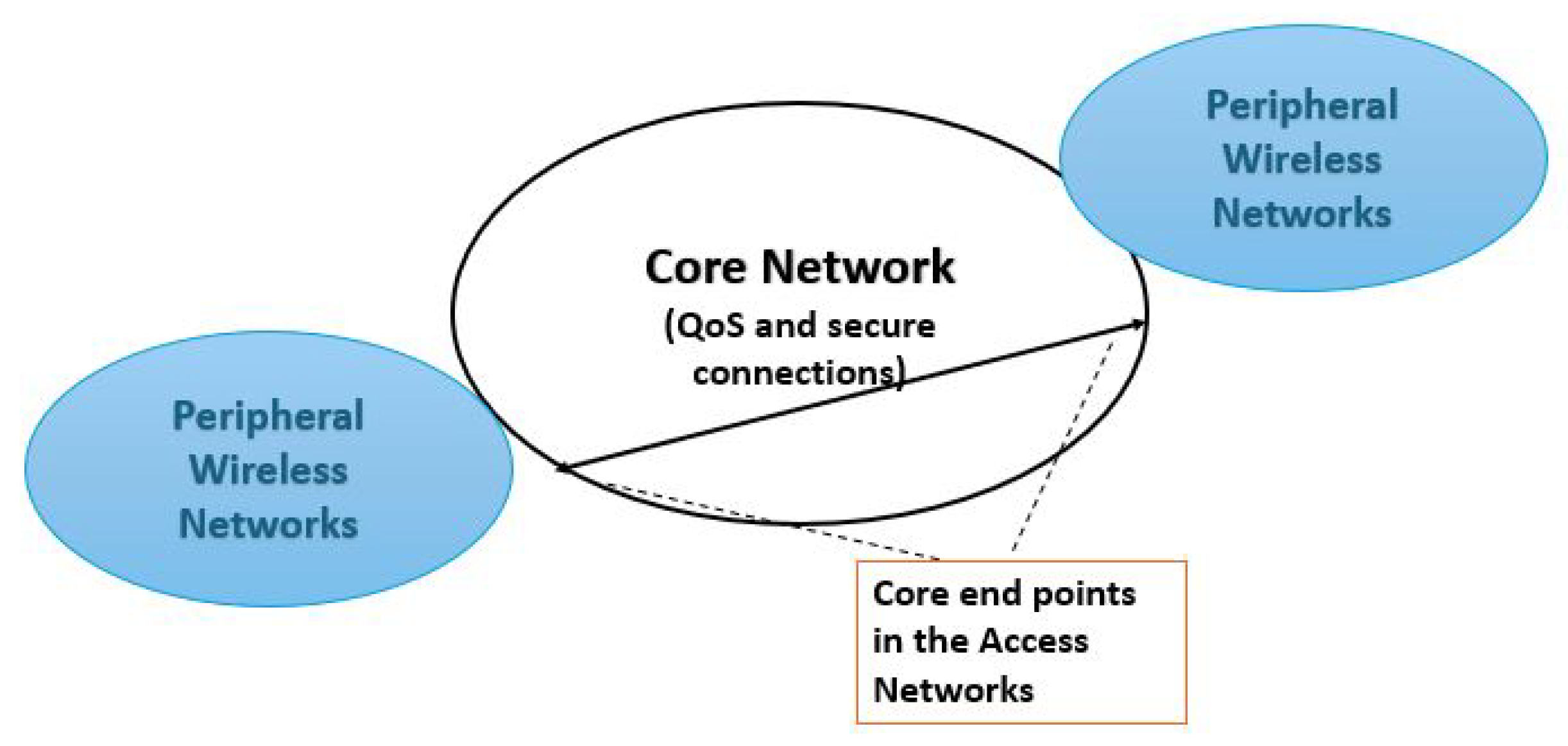
Figure 12.
Core End Points in the Access Networks.
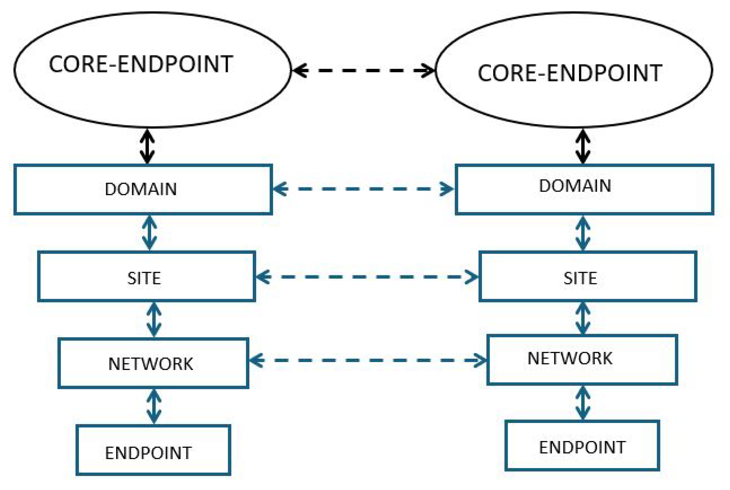

Table 1.
Routing Information to enable connections.
| Dest Parameters | Source Parameters |
|---|---|
| DEST ENDPOINT | SOURCE ENDPOINT |
| DEST HOST/NETWORK | SOURCE HOST/NETWORK |
| DEST SITE/DOMAIN | SOURCE SITE/DOMAIN |
| DEST COREPOINT | SOURCE COREPOINT |
Disclaimer/Publisher’s Note: The statements, opinions and data contained in all publications are solely those of the individual author(s) and contributor(s) and not of MDPI and/or the editor(s). MDPI and/or the editor(s) disclaim responsibility for any injury to people or property resulting from any ideas, methods, instructions or products referred to in the content. |
© 2025 by the authors. Licensee MDPI, Basel, Switzerland. This article is an open access article distributed under the terms and conditions of the Creative Commons Attribution (CC BY) license (http://creativecommons.org/licenses/by/4.0/).
Copyright: This open access article is published under a Creative Commons CC BY 4.0 license, which permit the free download, distribution, and reuse, provided that the author and preprint are cited in any reuse.


