Preprint
Review

This version is not peer-reviewed.

Recurrence of Primary Glomerular Disease Adter Kidney Transplantation: Incidence, Predictors, Characteristics and Treatment

A peer-reviewed article of this preprint also exists.

Submitted:

19 February 2025

Posted:

20 February 2025

You are already at the latest version

Abstract

In the application of the digital twin model of the digging face, the data transmission will be transmitted to the remote control platform through the physical hardware via the gateway, and this cross-system and cross-software data transmission mode will inevitably generate the transmission delay, which leads to a certain spatial-temporal deviation between the virtual scene of the remote control platform and the physical digging site. In this paper, by analyzing the operation process of roadheading equipment, a state evolution dynamics model construction method for roadheading equipment is proposed, which includes three stages, namely, discretization of positional state based on cutting path planning, event-driven construction of cutting state evolution map of roadheading equipment and real-time data-driven dynamics evolution of roadheading equipment, and the construction of roadheading equipment state evolution dynamics model provides the best solution for the roadheading equipment. The construction of the model provides theoretical basis and technical support for the construction and alignment of the digital twin multidimensional model of the roadheading equipment.

Keywords: 
;  ;  ;  ;  ;  

1. Introduction

China's coal mining industry is facing the challenge of insufficient level of mechanized mining, especially in roadway operations, where there are difficulties in multi-equipment cooperative work. At the same time, there is insufficient investment in intelligent rapid boring technology and its equipment, resulting in slow technological progress. These problems make the digging efficiency fail to synchronize with the coal mining efficiency. Therefore, solving the problem of mining imbalance has become particularly urgent and is an important issue that needs to be solved in China's coal mining industry[1].
In order to cope with the challenges facing the coal mining industry, the promotion of intelligent mining technology has become a common goal in the industry. This technology system covers digital coal seam modeling, virtual-real combination operation, data-based decision-making, real-time adjustment, virtual collision analysis, accurate cut-off prediction, and remote equipment control technology with human-machine collaboration. These technologies play a key role in the remote control of underground equipment in coal mines, and play a crucial role in solving key problems such as accurate identification of coal-rock interfaces, realization of efficient automated cutting, and real-time monitoring of abnormal status of equipment groups[2,3].
Digital twin is an innovative technology that accurately reflects the operational state of physical entities through real-time updated virtual models[4,5,6,7]. The key advantage of this technology is its interactivity and collaborative capability, where the virtual model is able to monitor the physical entity in real time using sensor data, realize dynamic mapping, and validate the control strategy in the virtual environment, and then control the physical entity[8]. This process involves communication and cooperation between physical devices, information exchange between virtual models, and synchronization and dynamic adjustment between virtual and physical models[9,10]. Although digital twins have achieved certain research results in the field of data acquisition and human-computer interaction, research on deep-level interaction and collaboration needs to be further deepened[11].
The concept of parallel system proposed by Prof. Feiyue Wang aims to optimize the goals of the actual system through the synergistic evolution, closed-loop feedback mechanism and two-way guidance between the actual system and the corresponding artificial virtual system[12,13]. Under this concept, the elusive “virtual” and “soft” elements of complex systems can be materialized and hardened through a series of quantifiable, executable, repeatable, and real-time computational experiments. This approach can effectively address multiple challenges in real-world complex systems, including, but not limited to, the unpredictability of behavior, the difficulty of decomposing and reducing structure, and the unrepeatability of experiments. Thus, parallel systems provide an innovative strategy for understanding and controlling complexity[14].
Prof. Tao Fei and his research team have carefully constructed a comprehensive digital twin connection and interaction theory system, which includes five key aspects, namely, perception, communication, mapping, linkage and integration, and provides an action guide for the effective application of digital twin technology. The “accurate, real-time, consistent, safe, and reliable” connection and interaction criteria proposed by them not only analyze each element in depth in the time dimension, but also establish theoretical links between elements in different dimensions, thus laying a solid foundation for the scientific and practicality of digital twin connection and interaction[15].
The article[16] proposes a multiresolution state-space discretization method incorporating pseudo-random networks for episodic unsupervised learning in Q-learning. This method is particularly suitable for closed-loop control of deformed or highly reconfigurable systems and can be used as an effective learning agent.
When the system encounters a large risk of latency or data loss, the gaps between data can be effectively filled by employing action interpolation to ensure continuous and smooth action simulation in the digital twin system, thus maintaining the realism of the virtual experience. In addition, by utilizing the memory truncation mode, the system is able to automatically perform data filling, retrieval, and real-time updating to mitigate the impact of data loss on the system performance and to improve the response speed and accuracy. The combined effect of these strategies enhances the stability and reliability of the digital twin system in the face of challenges, and provides efficient, secure, and intelligent technical support for related applications[17].
The event-driven control strategy is a periodic dynamic approach that uses carefully designed trigger conditions to optimize the control process. Only when these conditions are satisfied, the system updates the control instructions. This approach significantly reduces the communication frequency and eases the burden on the bus bandwidth, thus improving the efficiency and responsiveness of the whole system[18].
In the literature[19], the authors highlight that the goal of the Discrete Event Simulation (DES) model is to validate demand scenarios in non-automated processes through simulation and to optimize the decision making process. The article provides insights into the applicability of DES to non-automated processes in their digital twin role, especially with respect to the challenges faced when implementing Industry 4.0 solutions. The researchers propose a systematic approach to carry out DES projects that takes into account the integration with process data as well as the model updates necessary to adapt to changes in the real environment. The article details the application of DES models in real cases, covering the whole process from goal setting, system definition, conceptual model construction, computational model development, to model data updating, building interfaces with real processes, setting up future scenarios, executing periodic scenarios, and analyzing and decision making. Compared to traditional simulation projects, DES demonstrates the advantages of automated data collection, real-time or near-real-time analysis capabilities, wider range of applications, continuous decision support, user-friendly interface design, close integration with real processes, and different levels of autonomy when acting as a digital twin. These features make DES a powerful tool for decision support for complex process and system management in an Industry 4.0 environment.
In the literature[20], researchers present an innovative approach that builds a Digital Twin (DT) platform using a Deep Augmented Learning (DES) system connected to Internet of Things (IoT) devices. The purpose of this platform is to construct pathways for hospital patients, enabling near real-time monitoring and predictive simulation. In order to validate the effectiveness of this approach, the researchers also built an experimental platform to simulate real hospital behavior for testing. This proposed method provides a new technical tool for monitoring and predicting hospital patient pathways.
In the literature[21], researchers introduced an innovative Discrete Event Simulation (DES) tool to aid decision making in hospital space planning. The article demonstrates the application capabilities of this tool through a specific real-world example. The core functionality of this DES tool lies in the use of event simulation to validate demand scenarios for hospital space planning and integrates it with parametric design models, enabling its application in the Grasshopper plug-in for Rhinoceros CAD software. The tool consists of several key building blocks, including precise definition of space requirements, seamless compatibility with parametric modeling environments, and detailed simulation of patient flow. The development of this tool provides a new decision-aiding tool for hospital space planning.

2. Design Method

2.1. Dynamic Modeling of the State Evolution of Tunneling Equipment

Figure 1 shows the architecture of the state evolution dynamics model construction method for roadheading equipment, which mainly contains three parts, namely, the discretization of the positional state based on the cutting path planning, the event-driven construction of the cutting state evolution atlas of roadheading equipment, and the real-time data-driven dynamics evolution of the state evolution of roadheading equipment.
Based on the results of the truncated path planning, the critical state nodes are discretized unitarily, and each critical state node is described specifically and quantitatively by the fuselage positional state parameters and timestamps. This state description scheme is also applied to anomalous states as the basis for event state correlation.
The key state descriptions are used as node attributes to construct a state evolution map using Neo4j, and each state node should be internally bound to a trigger event based on the event state correlation results.
During the cutting operation, the positional key parameters of the boring equipment are collected in real time to monitor the operating status of the equipment, and the transmitted positional state parameters will be screened by the anomaly identification algorithm to determine whether anomalous perturbation events are occurring, and the anomalous state nodes caused by the events will be updated in the constructed state evolution mapping. In order to ensure the real-time feedback of the digital twin model to the physical device, a state leaping mechanism is introduced to regulate the alignment and synchronization of the virtual and real states.

2.2. Discretization of Positional States Based on Truncated Path Planning

Discrete state processing aims to translate the complexity of physical digging behavior into a measure that can be simulated and controlled in digital space. By dividing the continuous state space into discrete state nodes and analyzing these key nodes in depth, a precise grasp of the evolutionary path of the digging state is achieved.
Based on the cutting operation requirements, the S-shaped cutting path is planned to be implemented in the roadway section, as shown in Figure 2. The cutting head runs from coordinate SA to coordinate SH within a cross-section to complete the cutting work in the cross-section of the cross-section of the cross-section. In this process, the motion of the cutting head alternates between vertical and horizontal directions, and each node where the operation mode alternates is defined as a key state node. According to this cutting path, when the cutting state is discretized, it is divided into eight key state nodes from SA to SH as shown in the figure, and the quantitative description of each state node contains the 10 positional state parameters shown in Table 1.

2.3. Event-Driven Construction of Cutoff State Evolution Mapping for Roadheading Equipment

2.3.1. Roadheader Operation State Evolution Relationship and Mapping Construction

(1) Static map construction methods
As shown in Figure 3, according to the results of the discretization of the cut-off state, in the ideal case, the position of the cut-off equipment will be changed sequentially from state SA to SH.
The description of the relationship between the nodes of the graph can be based on the change value of the specific attitude parameter, for example, during the change of the equipment from state SA to state SB, the slewing angle of the rotary platform of the cutter arm changes unidirectionally by Δα units. During the transition from state SB to state SC, the lifting angle of the cutter arm changes unidirectionally by Δγ units. Accordingly, the inter-nodal relationship between the state nodes SA and SB can be expressed as α+=Δα, and the inter-nodal relationship between SB and SC can be expressed as γ+=Δγ.
(2) Dynamic Mapping Evolutionary Logic
In the process of tunneling operation, due to the complexity of the underground operating environment, the operation process will inevitably encounter a variety of disturbing events, which will have a certain impact on the cutting state resulting in cutting abnormalities. For example, as shown in Figure 4, in the cutting process from state SA to state SB, the reaction force of the cutting head may cause the machine body to slide sideways, and the constant state maintained by the broken ring itself, at this time, when cutting according to the established operation plan, it will not be able to ensure the effective cutting quality.
If the current fuselage slip event is regarded as an abnormal perturbation event, then the original fuselage attitude state evolution map must be dynamically changed in order to ensure the real reliability of the map feedback. The abnormal perturbation occurs during the transition from state SA to SB, then the relationship between the nodes of the mapping SA and SB will be changed, and a new abnormal state node will be added between the two due to the perturbation event. As shown in Figure 5, the planned state node at the moment before the anomalous state is generated will be recorded as the M1 intermediate state node, and at the same time, M1 will be used as the target node for the correction of this anomalous state in order to ensure that the evolution of the state node graph returns to normal.
During remote intelligent boring operations, abnormal disturbance events can cause the original cutting path to be disrupted at any time. In order to ensure the quality of the remote intelligent roadheading operation, adjustments must be made to restore the roadheading state to the intended route when the operation state is disturbed. In this context, the state evolution network of the boring face needs to realize closed-loop control when abnormal state branches appear, i.e., it automatically corrects the abnormal changes in the boring state caused by disturbances and returns to the planned operation path, as shown in Figure 6.
In the figure, M4 and M7 are both intermediate state nodes of the same type as M1 within the established state evolution path. In addition, the downtime mechanism at the time of perturbation enhances the executability of the state regression, and the anomalous state nodes return to the planned state evolution network with the intermediate state nodes as the evolution target.

2.3.2. Event State Model

The automated change of mapping relies on event triggering, which presupposes a certain judgment scheme for the occurrence of anomalies. Monitoring the acceleration change of the cutting key action is essential to determine whether the operational event has changed. Under normal operation, the cutting key action is performed at a uniform speed, and the fluctuation of acceleration can be used to determine whether the current state is abnormal or not. Taking the rotary motion of the platform as an example, the current rotary speed and acceleration can be calculated by the following formula, involving the current time and the specific rotary angle:
S α i = α i α i 1 ÷ T i T i 1
S α i = S α i S α i 1 ÷ T i T i 1
By monitoring these parameters, it is possible to determine whether the operational status is normal and to take appropriate measures to ensure the continuity and safety of operations. If there are abnormal fluctuations in acceleration, this may indicate a problem in the operation and require adjustment or shutdown for inspection.
Operational status S definitions include time stamp, slew angle, lift angle, and reach length. Changes in the acceleration of critical movements are usually caused by two reasons: movement adjustments that follow operating instructions, and movement deformations caused by external perturbations. In the movement change caused by control instructions, the operation state should be stable before and after the change, and each acceleration should be close to zero. The magnitude and duration of acceleration changes should be consistent with the control instructions, which helps to determine the precise range of action changes. The action deformation caused by the disturbance may cause irregular changes in acceleration. By observing whether the acceleration is zero, combined with the execution time of the control instructions, it can further determine whether the operation behavior is abnormal.
If the change in acceleration does not match the control command or remains non-zero outside of the control command execution period, it may indicate that the operational behavior is affected by the disturbance. At this time, corrective or adjustment measures need to be taken to ensure the quality and safety of the operation. Through this method, the operation status during remote intelligent digging can be effectively monitored and controlled to respond to various perturbation events in a timely manner.
The definition of events and the description method have a direct impact on the event detection and extraction program. The definition of events should cover the behaviors triggered by control instructions in the established operation plan, as well as the disturbing events caused by the complex underground environment, which are beyond the operation plan.
The core of event exploration lies in mastering and controlling the digging state, therefore, the description method of events can be determined based on the definition model of the state. The digging state is defined and described through two dimensions: time node and space position, and the state is discretized according to the operation plan. Each transition of the state node marks an important change of the key parameters of the roadheading equipment, which can be regarded as the triggering of a planned event. Therefore, an event can be understood as the cause of a state change. Based on the discretization of the state and the definition of key state nodes, events can be defined based on changes in key action parameters of the cutter arm.
As shown in Figure 7, each state node is preceded by a corresponding event node. Events a-h are triggered by the planned operation instructions, which cause the state of the tunneling operation to change in an orderly manner according to the established plan. Events E1, E4 and E7 are caused by parameter shifts due to unexpected situations, and the occurrence of such disturbing events leads to the shift of the operation state beyond the planned threshold, thus failing to guarantee the operation quality. Based on the correspondence between events and states, events can be defined vectorially, e.g., Ea = {a, SA}, E1 = {E1, 1}, etc. This definition method helps to clarify the relationship between events and state changes and provides a basis for event detection and processing. Through this method, the events in the boring process can be accurately captured and described, and then effective state control can be realized.

2.3.3. Storage Model for Events and States

Building a state evolution network requires storing and retrieving historical states, and event state models require libraries to record historical events. The perturbation event states that occurred in the previous intercept are incorporated into the existing state set as the starting state evolution network for the new intercept. With the accumulation of data from multiple intercepts, the state evolution network will be more comprehensive in covering the perturbation event states, thus improving the accuracy of the state evolution network-based roadheader position recognition and control.
The incoming established event states are based on key features of previous states, including threshold descriptions. To reduce the computational burden in the evolution process, the established event states and perturbed event states should be stored in a unified mode. However, the perturbation event states do not require threshold delineation, so the threshold descriptions of the key feature values are not included when storing such states. Therefore, a unified storage model should be designed for these two different categories of events. The event states are categorized and stored hierarchically according to the division of the state thresholds and the different stages of the truncation operation, using the threshold division results as the criteria for determining the state intervals, and the state descriptions are based on the current spatial and temporal attitude parameters, and the state points within different state intervals are defined as different types.
In the same truncation path, different perturbation states are categorized as the same type. For example, in Figure 8, the three potential perturbation event states derived during the transition from state SA to SB are all considered to be of type 1. Despite the fact that these events belong to the same type, there are significant differences between them. These differences arise because multiple error accumulations are experienced as the state deviates from the normal path, and the type and degree of error is influenced by the specific scenario, resulting in anomalies of the same type that may end up being very different. Therefore, the hierarchical classification storage scheme adopted is actually an organization of the irregular state evolution process.
As shown in Figure 9, the different truncation phases are categorized into different types that constitute the highest level of branching structure. Within each stage, the error categories are first categorized into three main categories based on the key parameters. Following this, two types, positive and negative deviation, are distinguished based on the direction of deviation of each parameter. Ultimately, the deviation intensity is determined based on the specific amount of deviation and further subdivided into deviation classes. In the storage process, the corresponding data hierarchical relationships are constructed in the database according to these types and levels. The establishment of each branch of deviation types is equivalent to providing index labels for time retrieval, and ultimately the depth of retrieval is determined based on the degree of deviation, thus determining the event tree structure of an event. This approach helps to improve the efficiency and accuracy of event retrieval.

2.4. Real-Time Data-Driven Dynamics Evolution of State Evolution of Roadheading Equipment

2.4.1. Anomaly Recognition Algorithm

The basis of model operation lies in the ability to identify anomalous states; how to identify event state types has been discussed above, and state identification, i.e., the method of identifying event state types, is critical to the endogenous evolution of the model's dynamics.
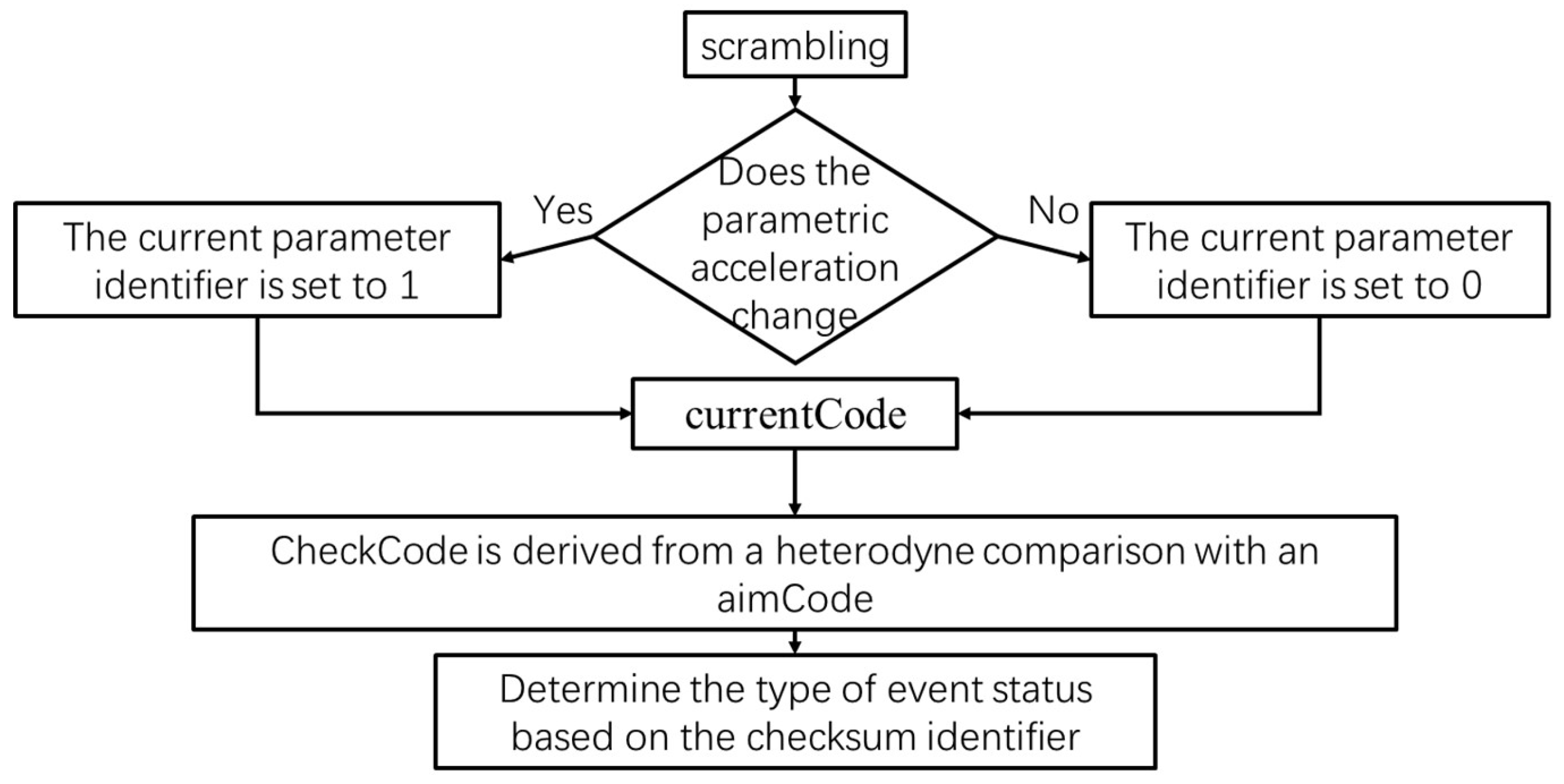
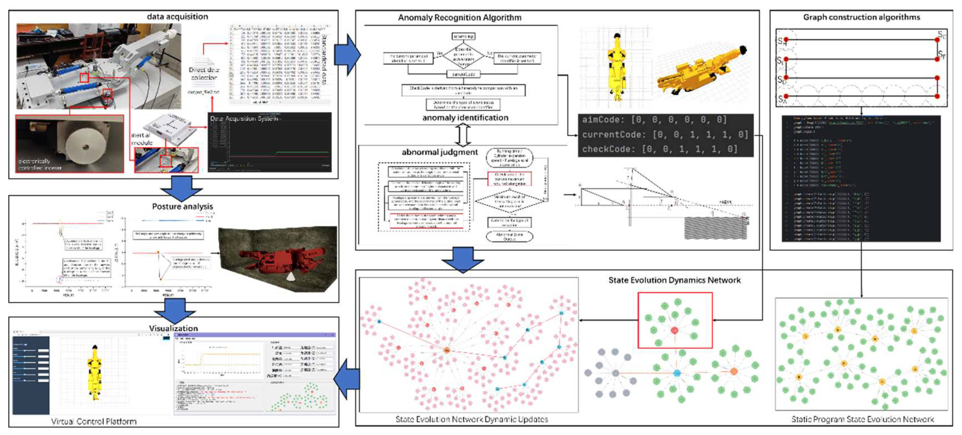
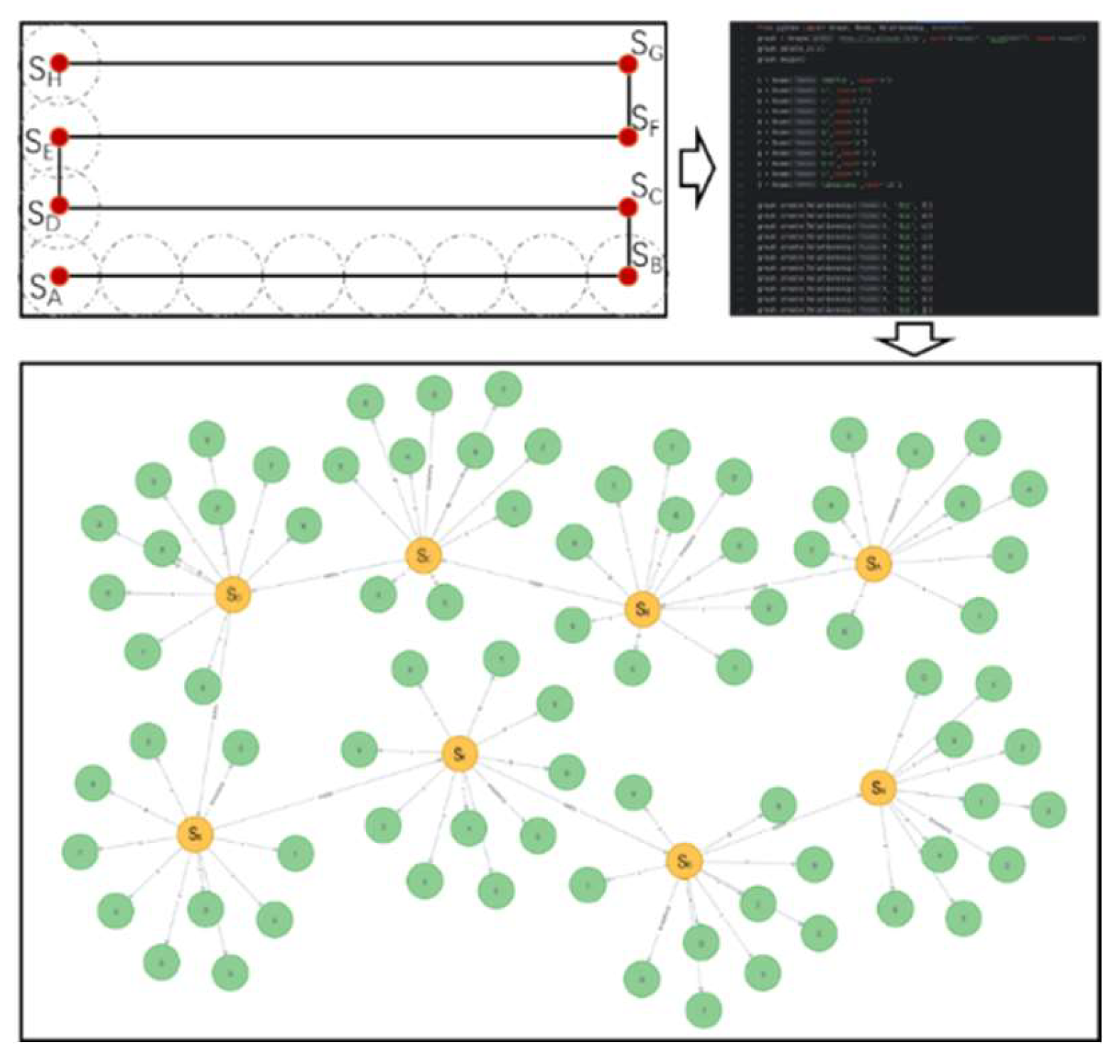
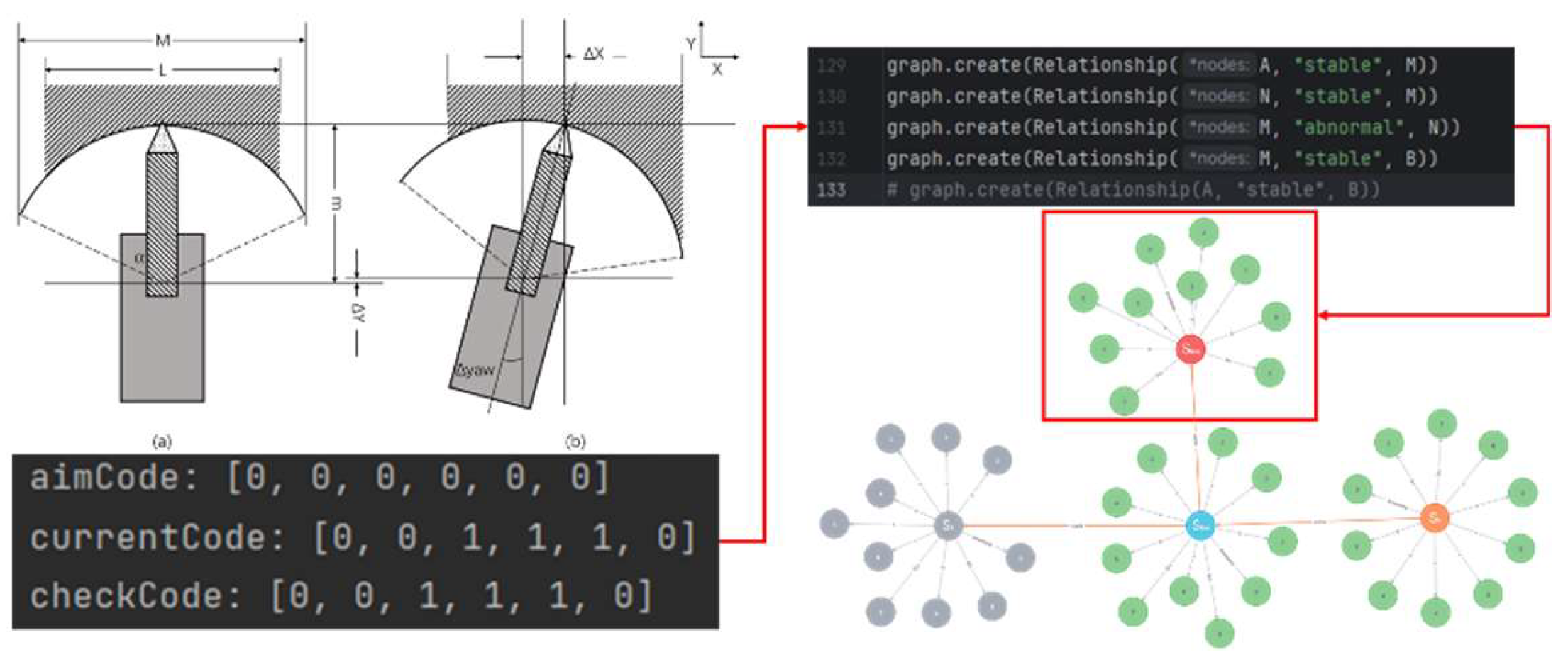
The state identification algorithm is shown in Figure 10. The anomaly type recognition algorithm consists of three state identifiers: aimCode, currentCode, and checkCode, which are consistently judged through an iso-or relationship. A 0 or 1 in these identifiers represents a change in the acceleration of a parameter at the current timestamp, with a change being a 1 and no change being a 0. The aimCode represents an airframe control command event at the current timestamp. For example, during the process of cutting operation from state S
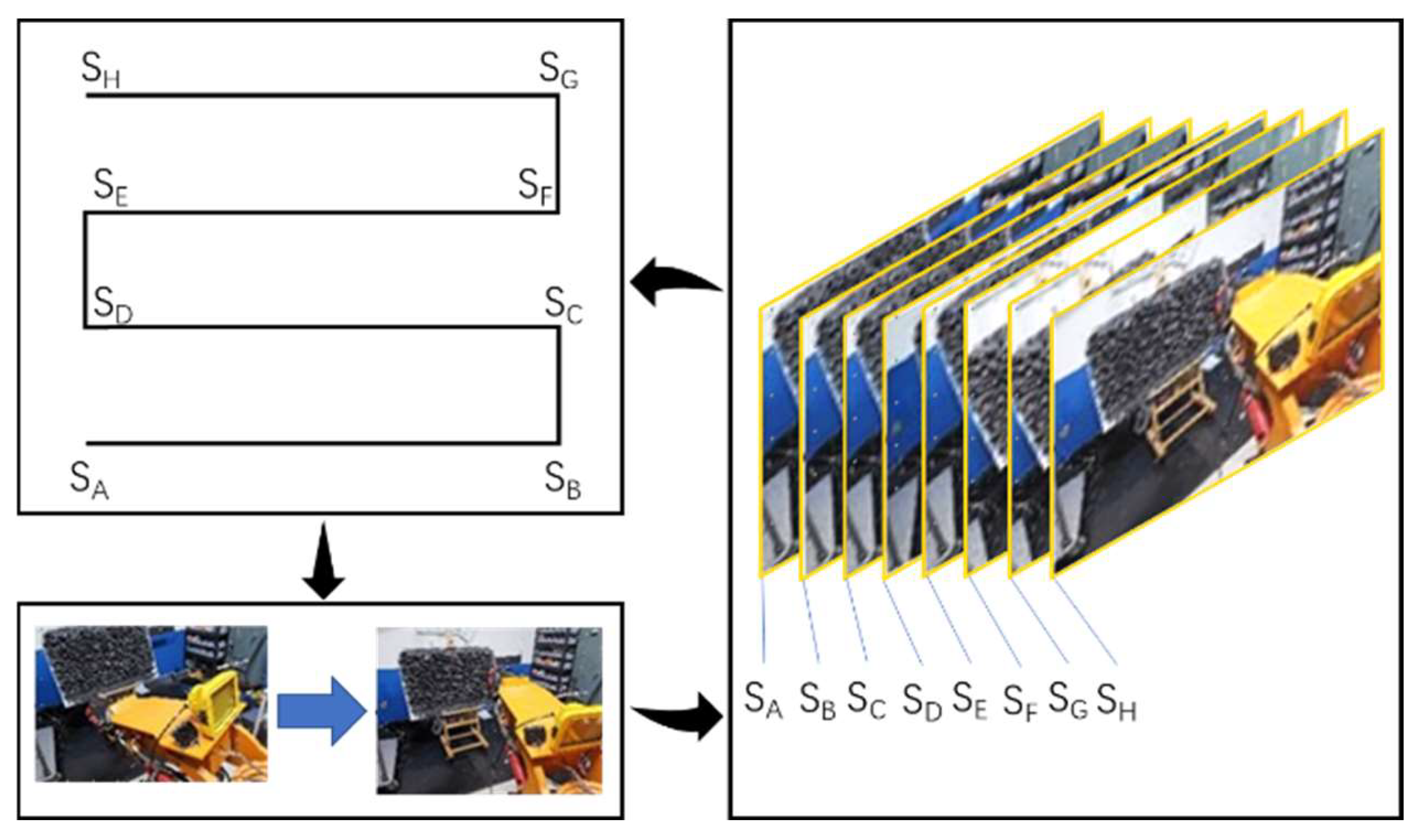
A to SB, the system needs to adjust the motion mode, stop slewing and start lifting the cutting arm, and the overall body position remains unchanged. Taking the case of not considering the cutting arm extension and retraction as an example, the system command event identifier at S
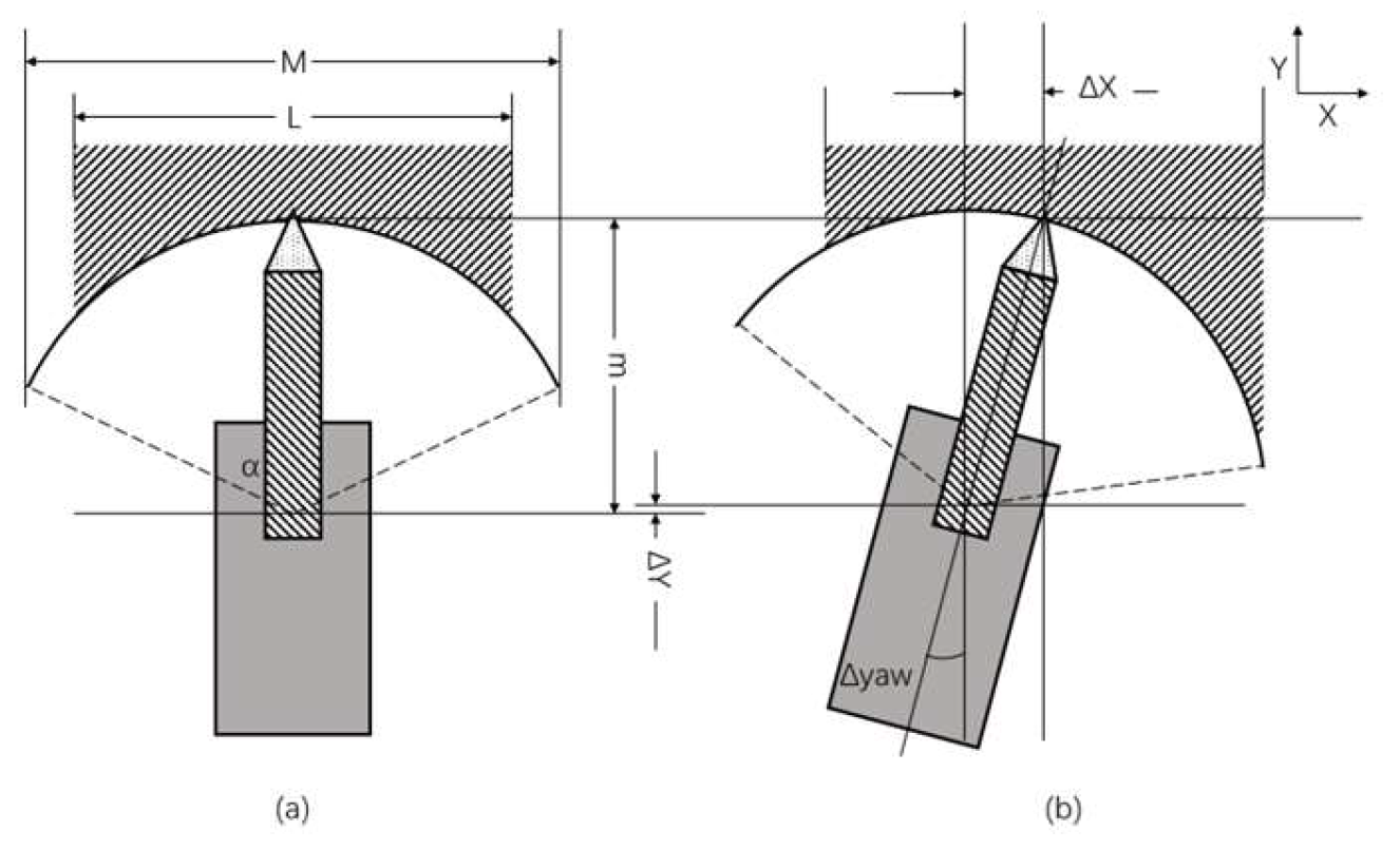
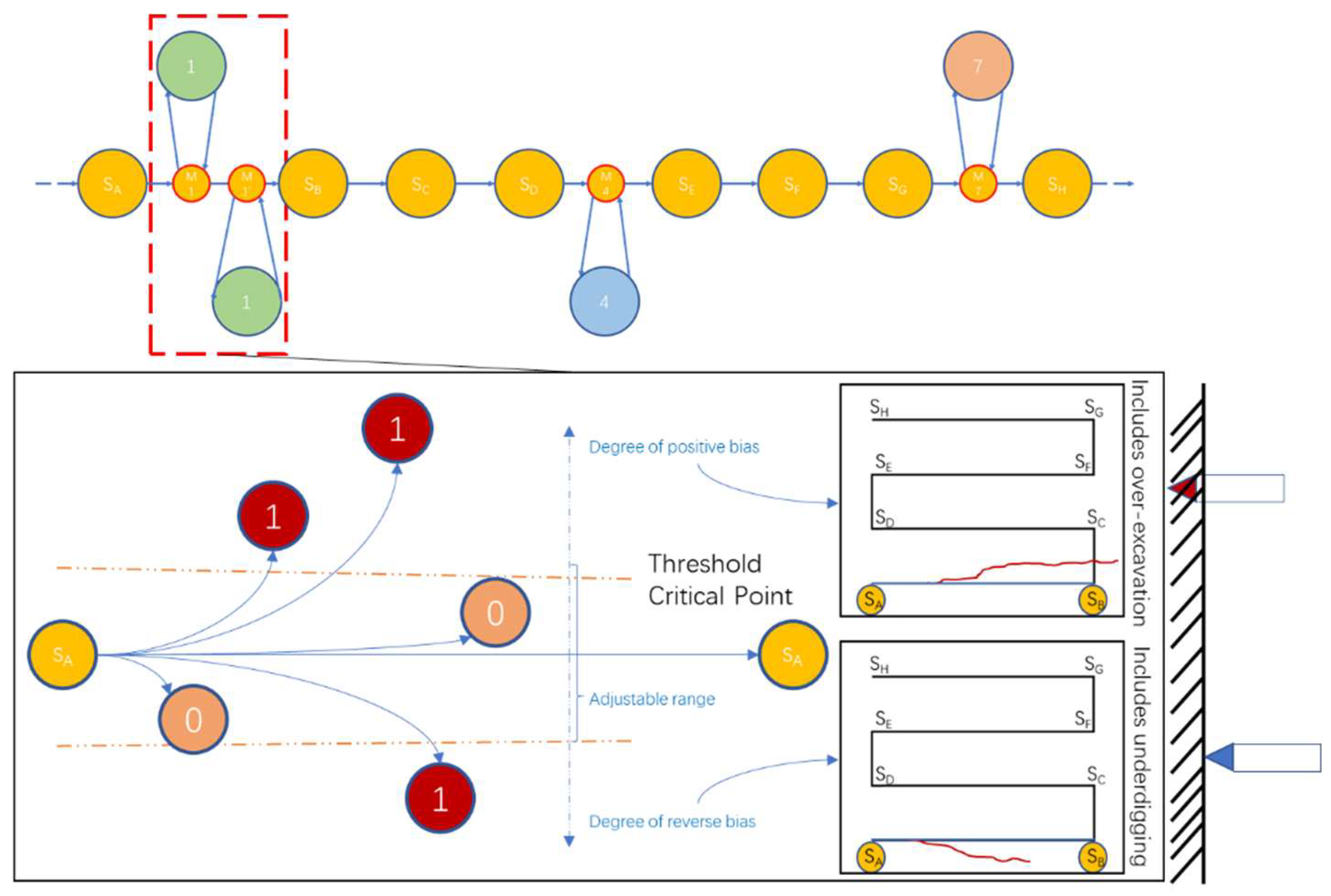
B should be T110000000, T stands for the time stamp of the system command, and the numbers from the left to the right represent the platform slewing acceleration, the cutting arm lifting angle acceleration, the cutting arm retraction and retraction, the spatial coordinates of X, Y and Z, the fuselage yaw angle H acceleration, the fuselage pitch angle P acceleration, and the fuselage roll angle B acceleration. The other parameters are 0 if they are unchanged, the rotary platform rotary angle acceleration becomes negative when the slewing stops, and the cutter arm lifting angle acceleration increases suddenly when the lifting starts. As shown in 
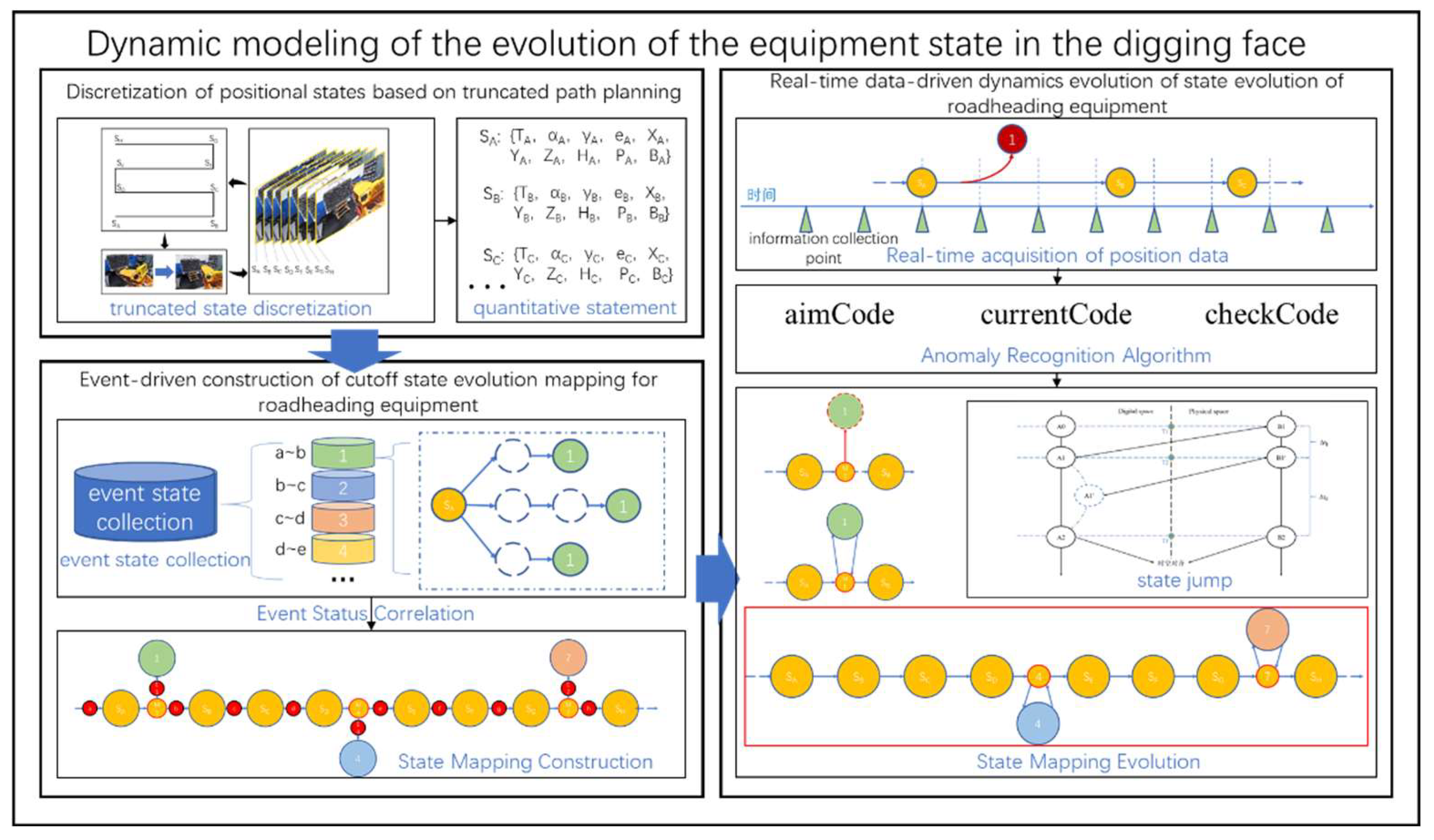
Figure 7, abnormal perturbations usually occur in non-system command bits. Under these conditions, when branch state node 1 is generated, the digging state should maintain the original operation state, i.e., the aimCode should be 000000000. if the current abnormality is the lifting angle abnormality, the corresponding acceleration of the lifting angle will change, i.e., the current state identification code currentCode is 010000000. Comparing aimCode and currentCode, we can get the specific variable of unplanned change, i.e. checkCode is 010000000. according to checkCode, we can determine the type of current event.
Before constructing the event triggering mechanism, it is crucial to clarify its role and the significance of its construction. The core objective of the mechanism is to ensure the synchronization of the virtual and real in the remote intelligent tunneling process. In the current synchronization scheme, the virtual control platform and the physical digging site synchronize their operations according to the instructions of the operation plan. If the digging site encounters disturbances that lead to unplanned changes in the operation status, the virtual-real synchronization that was originally maintained by synchronizing the operation instructions will be destroyed. The virtual tunneling scene needs to be adjusted according to the real data feedback from the physical tunneling site, but this process generates a time delay. If the virtual scene digging state is adjusted in real time according to the site data, the virtual digging scene will always lag behind the real digging site, which can not accurately reflect the current digging state, affecting the corrective decision-making of the remote intelligent digging system on digging anomalies. Event triggering mechanism identifies the disturbance event when it occurs and adjusts the virtual synchronization strategy.
When a change in the digging status is detected by acceleration comparison, the value of the specific parameter change is calculated and compared with the last two control instruction change nodes. If the established operation control instructions do not contain the current change, it means that the state change is caused by a disturbance event.
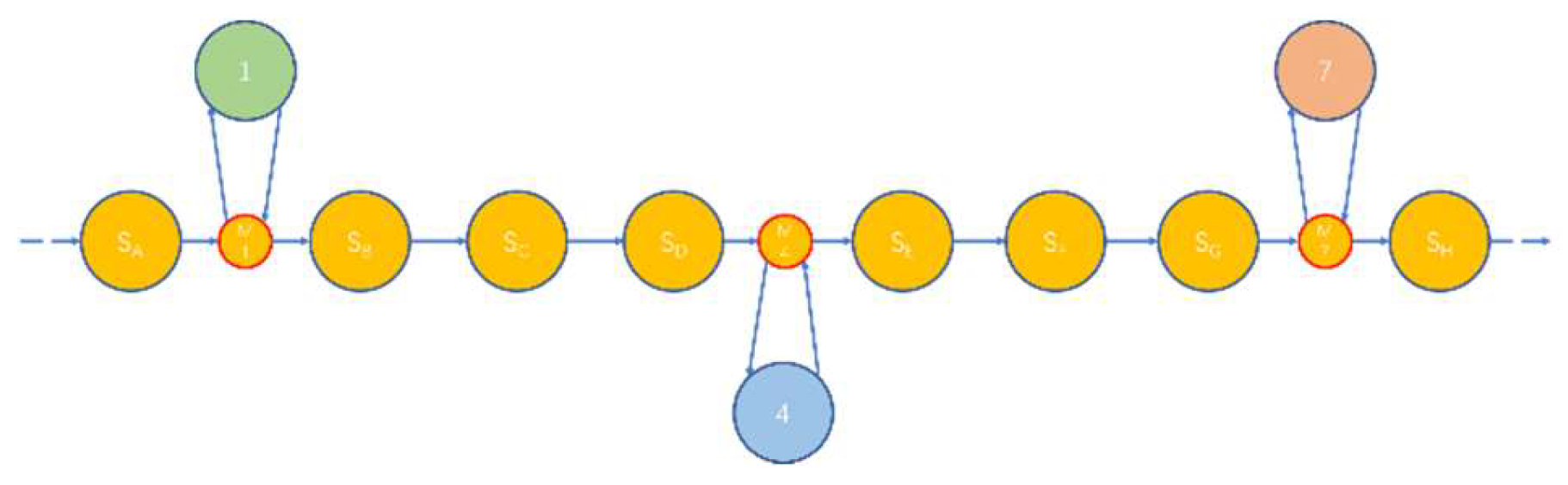
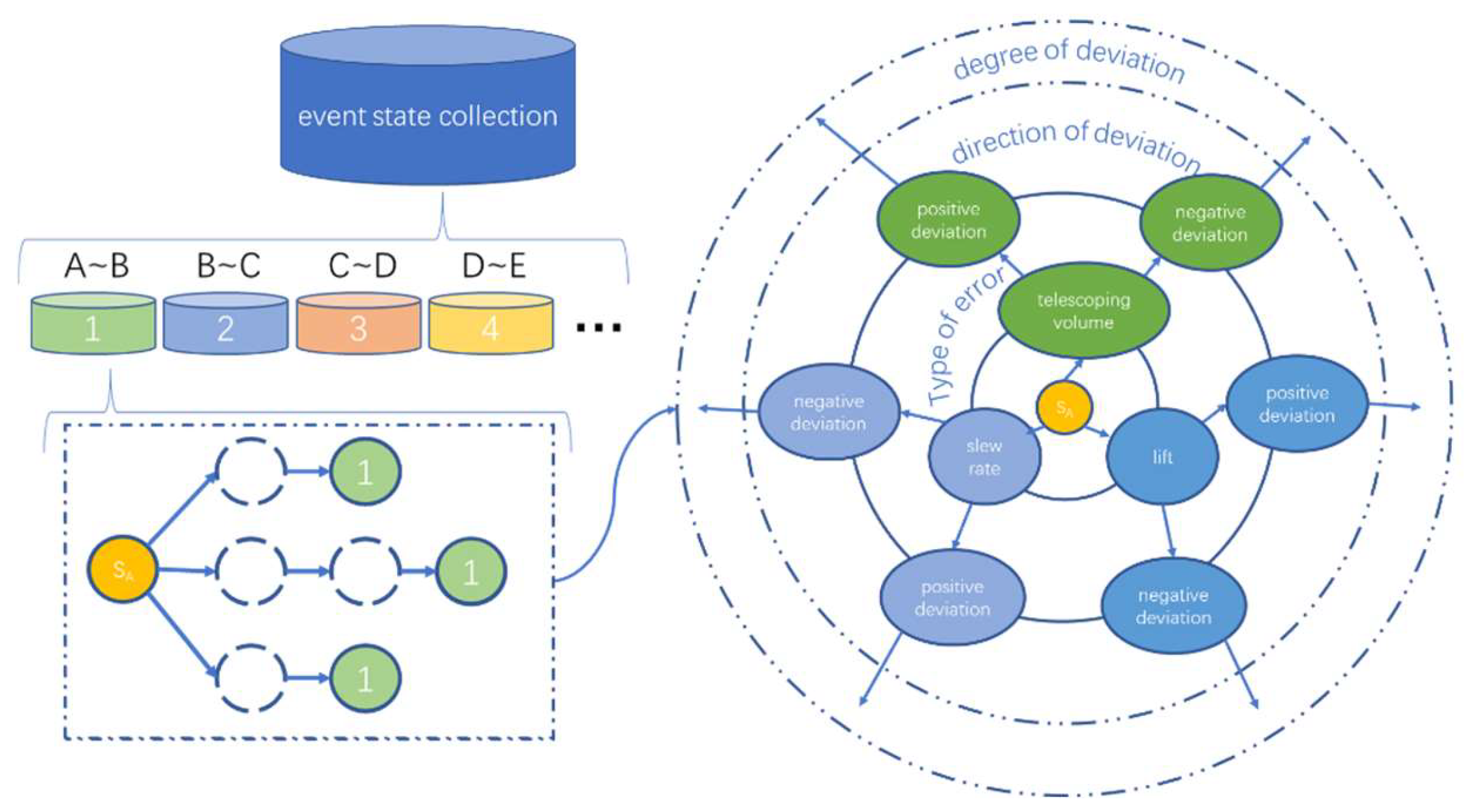
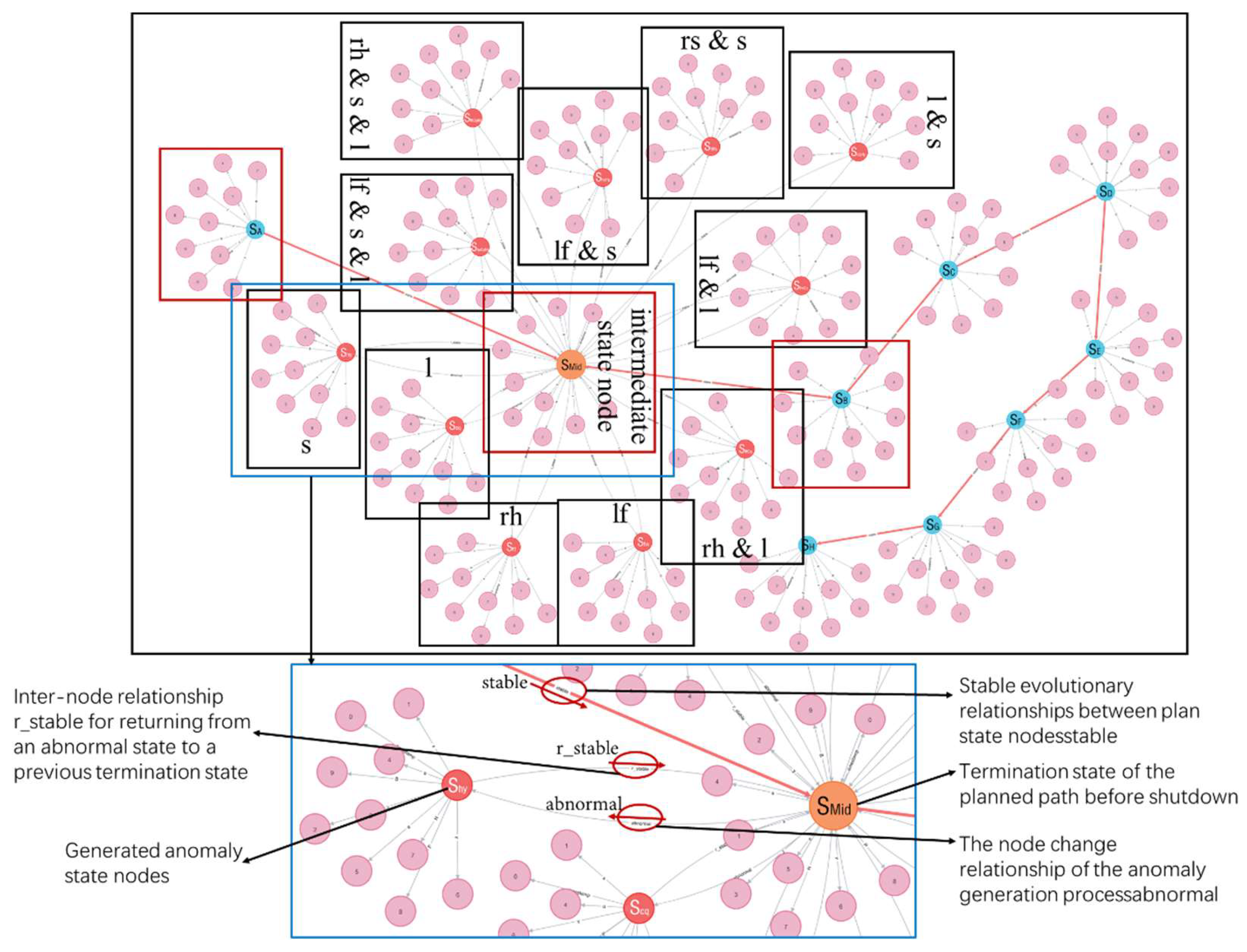
Determining the class of perturbation events is crucial to change the virtual real alignment strategy. The state evolution network contains various event trees, as shown in Figure 11. Based on the event tree structure after the current state change, according to the categorized hierarchical storage model, starting from the type of stage at which the event occurs, one by one, downward comparison with the event trees already existing in the network is filtered. If the same event tree exists in the formed state evolution network, the strategy to correct the current perturbation is determined based on the historical processing scheme of the corresponding event. If the search and comparison results show that it does not exist, a new strategy needs to be formulated based on the current specific situation, and the new event tree is bound to the current processing strategy and stored into the existing state evolution network.

2.4.2. Real-Time Data-Driven

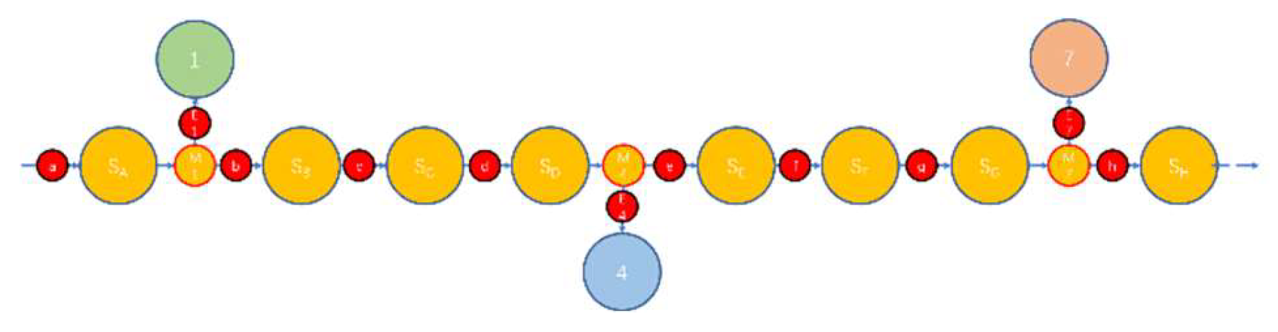
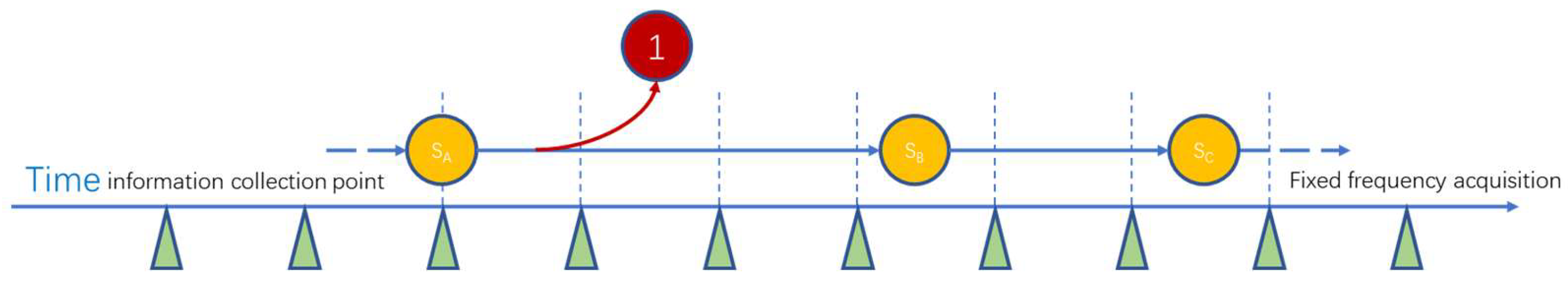
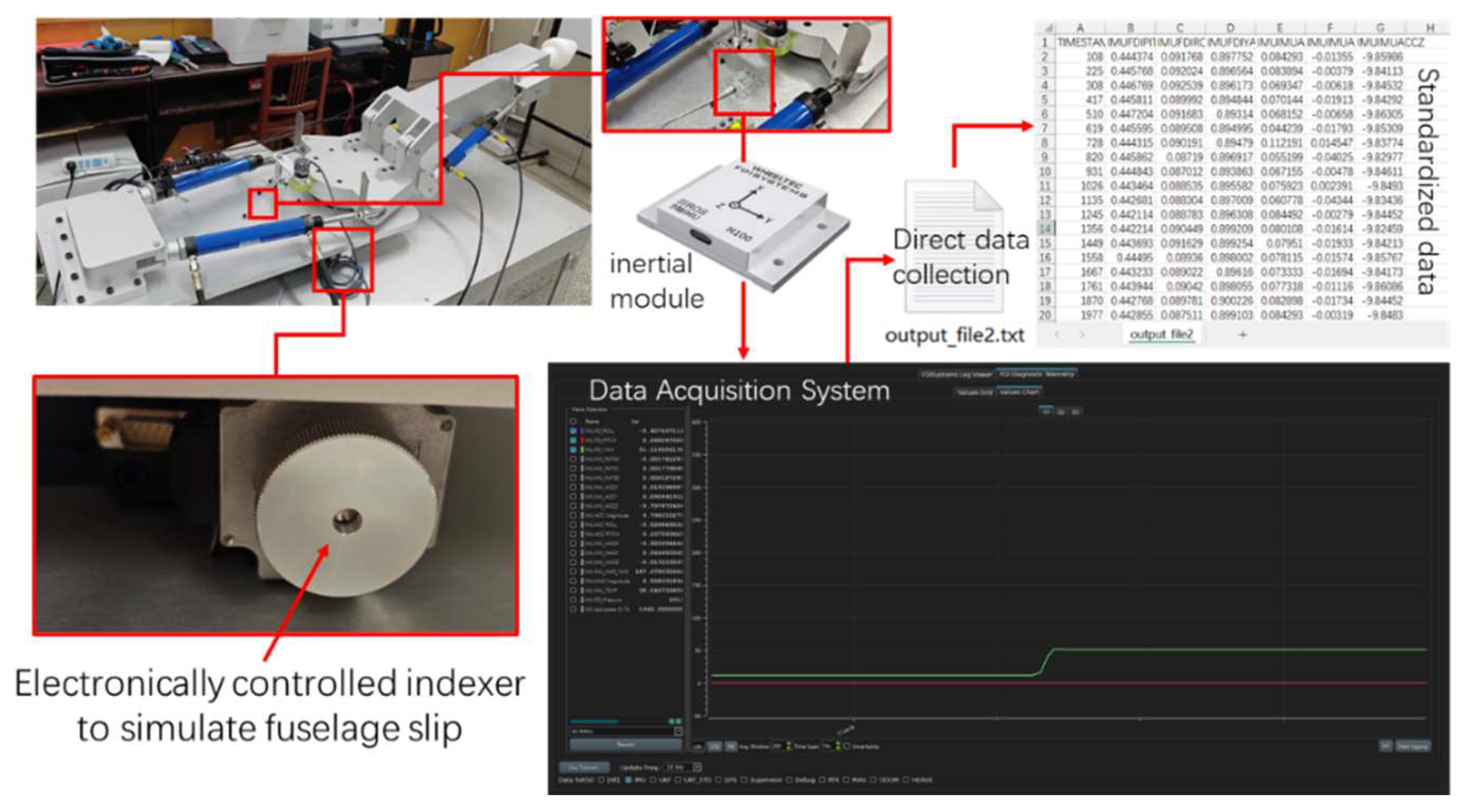
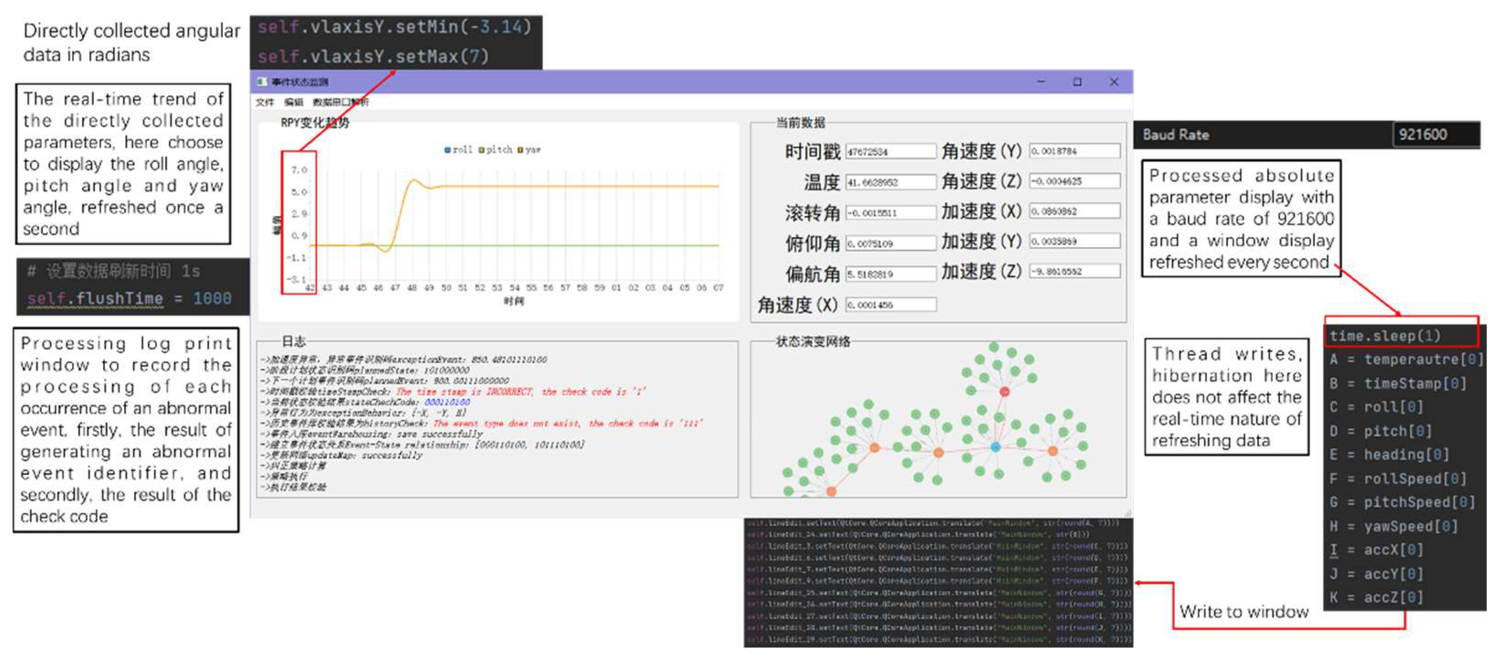
First, data are collected at a fixed frequency to monitor changes in equipment position parameters. The key parameters of the device, such as position, attitude, and velocity, can be accurately tracked mainly by periodically collecting them. A schematic diagram of real-time data acquisition is shown in Figure 12. The data acquisition system operates at a preset fixed frequency, e.g., once per second or multiple times per second, depending on the operating characteristics of the equipment and the required monitoring accuracy. Each time data is collected it is instantly processed and analyzed to determine if the equipment is in normal operating condition. If an abnormal change in a monitored parameter is detected, the system immediately triggers a subsequent processing program. This process is automated, ensuring a rapid response to abnormal conditions.
Detection of abnormal changes is accomplished by setting normal ranges or thresholds for parameters. As soon as a parameter falls outside these preset ranges, the system recognizes the abnormality and initiates the appropriate processing. This involves not only automatically adjusting equipment settings or performing operations such as emergency shutdowns, but also issuing alarms to notify operators to prevent potential equipment damage or production accidents.
In addition, the mechanism is able to record the exact time the anomaly occurred and the stage of operation the equipment was in. This is critical for subsequent troubleshooting and system optimization, as it provides detailed timeline and contextual information to help engineers analyze why the anomaly occurred and take targeted measures for improvement.
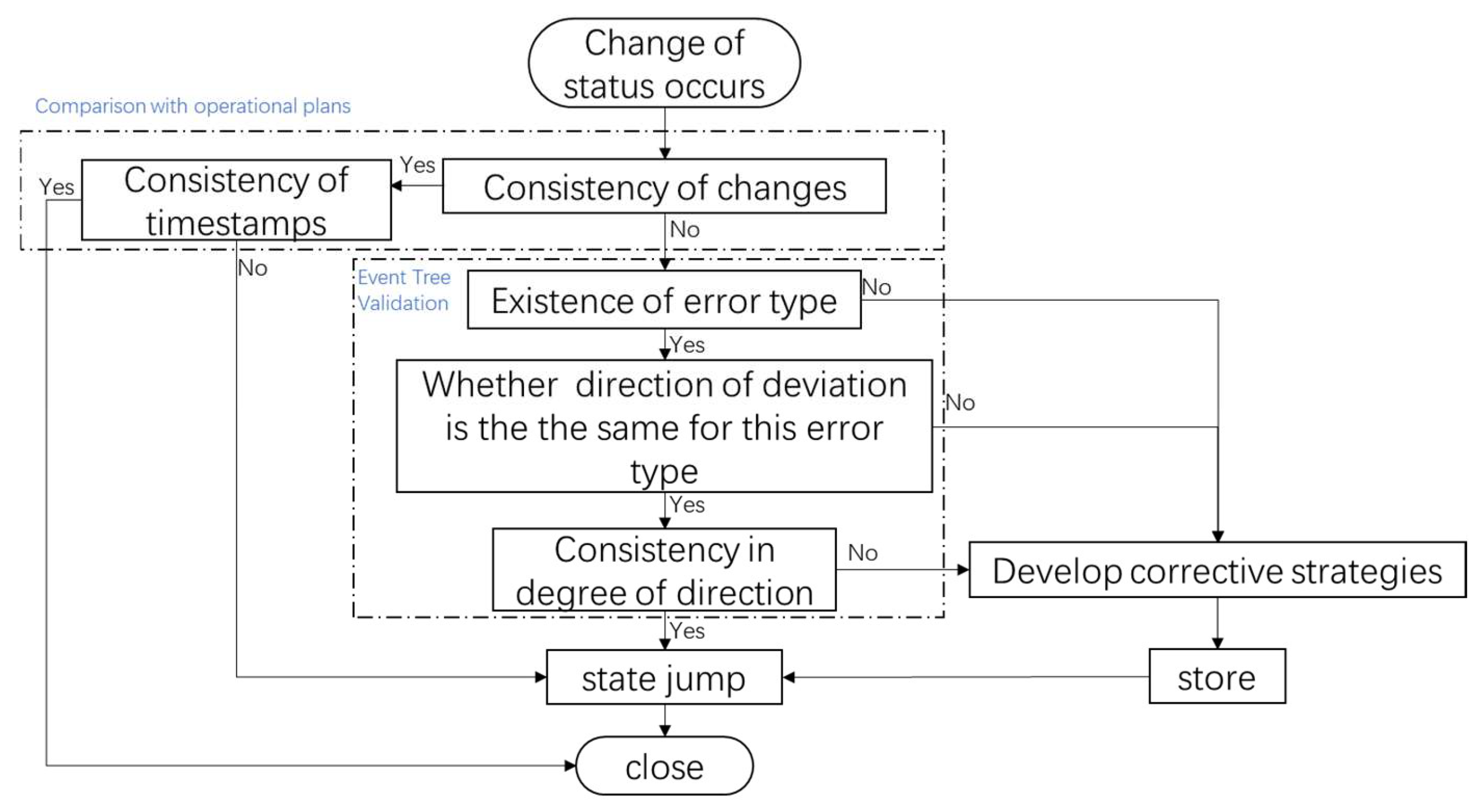
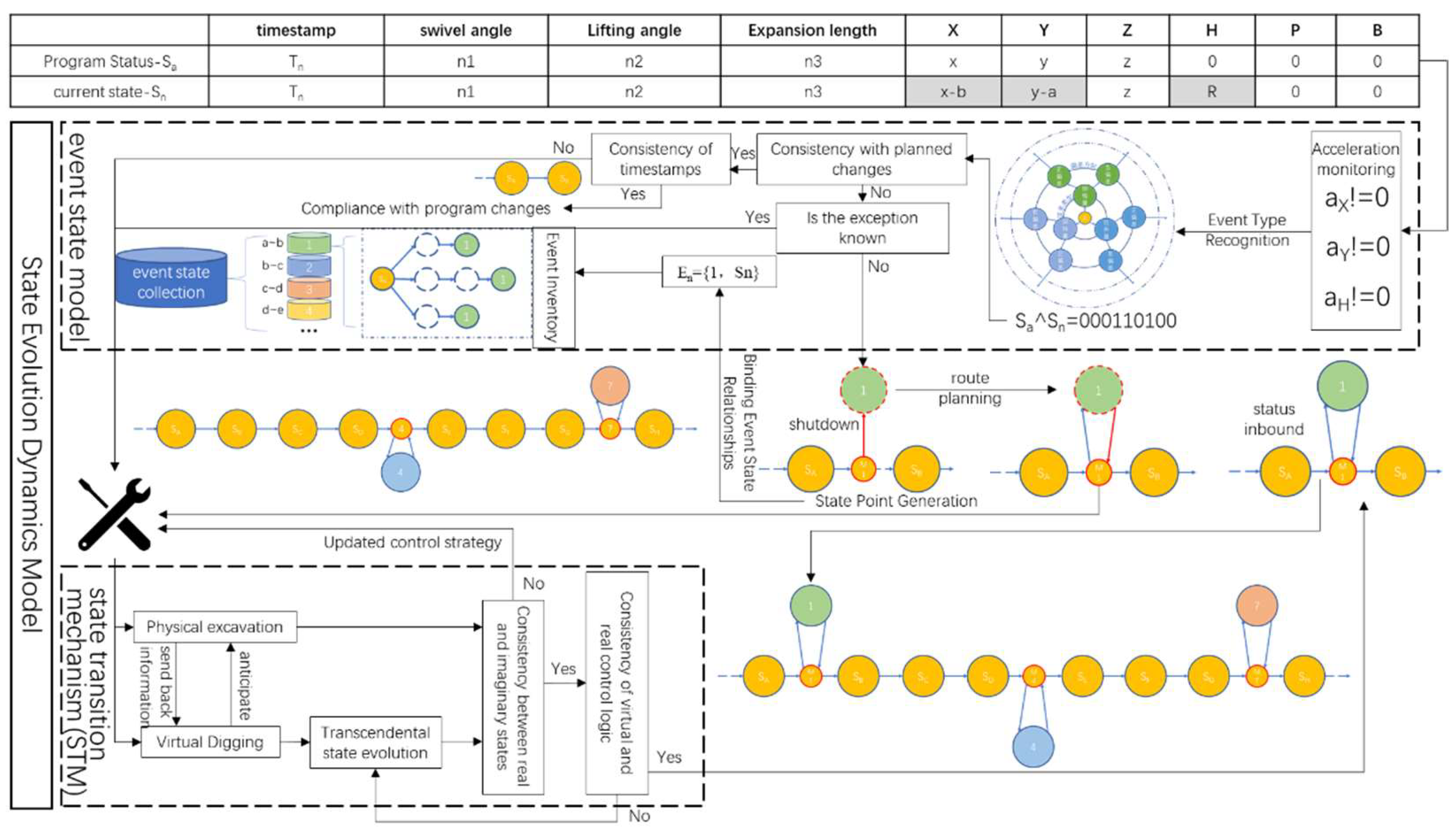
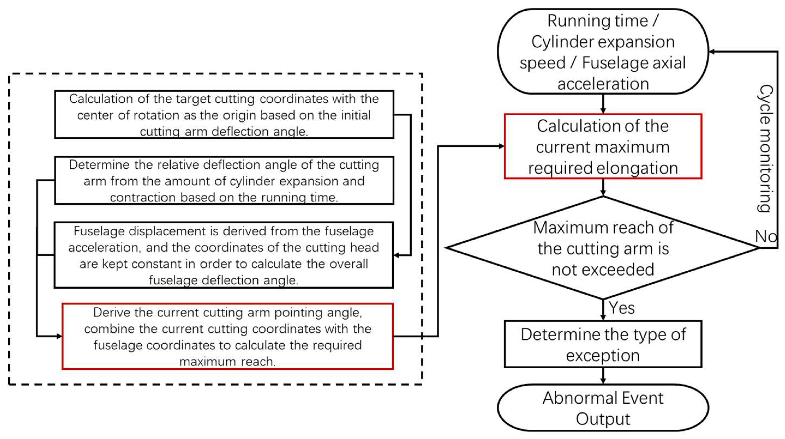
Real-time data drive will be used as a guarantee of the timeliness of the event triggering of the model in this paper, and the specific flow logic of the event triggering is shown in Figure 13, which sequentially connects the modules in series according to the flow direction of the perturbation event information, and the fuselage slipping event is used as an example to illustrate the operation mechanism of the state evolution dynamics model.
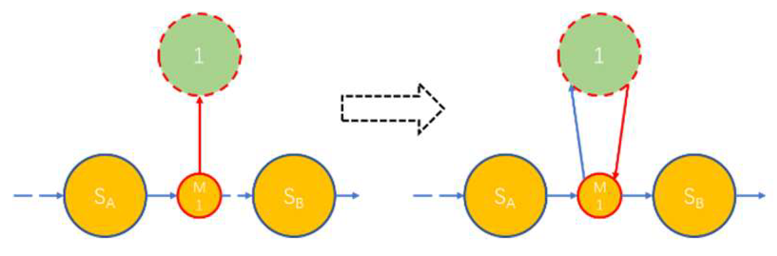
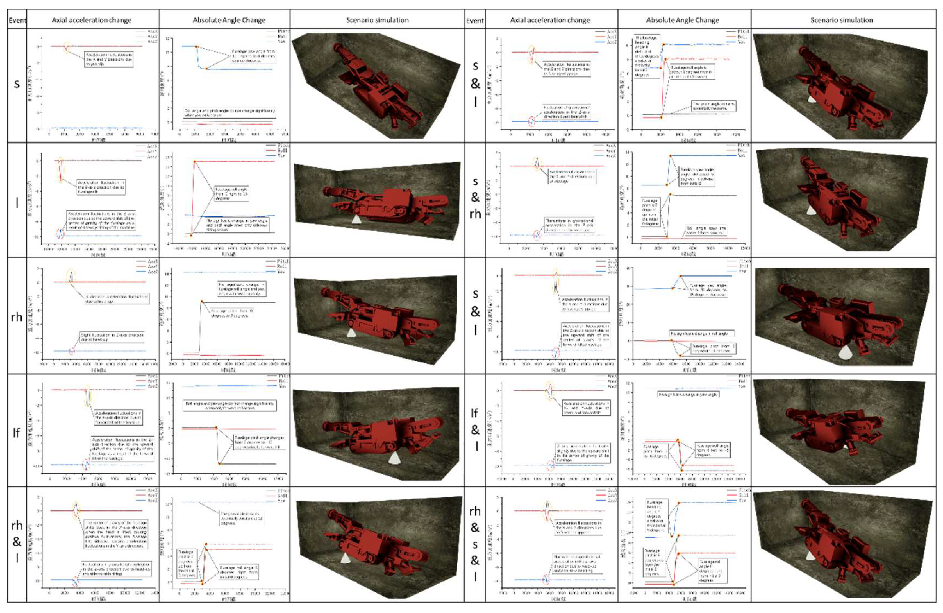
When fuselage slip occurs, the coordinate positions (X, Y) as well as the orientation (H) of the fuselage undergoes different degrees of change. At time point Tn, by monitoring the acceleration changes of X, Y and H, the event state model is able to recognize the truncated state transition. By performing the different-or-other (XOR) operation on the actual state parameters and the planned state parameters, a result of 000110100 is obtained.Based on this result, the type of perturbation of the current event can be identified and compared with the historical event database to determine if the event type has been recorded. If the event matching result indicates that the type is known, the corresponding historical processing scheme is immediately activated. Conversely, if the matching result indicates that the current event type is unprecedented, a new state node 1 is created in the state evolution dynamics model and the state is associated with the event type, the event state vector En={1, Sn} is constructed, and the event is recorded according to the storage rules of the event database.
A fuselage slip event results in a shift in fuselage coordinates (X, Y) and fuselage orientation (H). By monitoring the acceleration changes of X, Y and H at a specific moment Tn, the event state model is able to recognize the changes in the truncated state. The result 000110100 is obtained by performing a different-or-or (XOR) operation on the actual state parameters and the planned state parameters.Based on this result, the perturbation type of the current event can be determined and matched with the historical event library to determine if the event type has been recorded. If the matching result indicates that the event type is known, the corresponding historical processing scheme is automatically executed. If it is a new event type, a new state node 1 is created in the state evolution dynamics model and the state is bound to the event type to form the event state vector En={1, Sn} and saved to the event library.
Emerging state nodes, triggered by unknown events, generate branches in the original state evolution network. Depending on the details of the state offsets and the criteria of the job plan, a path needs to be planned to guide the current abnormal state back to the normal state before the next scheduled job change node. Based on the results of the path planning, a control strategy for the state change can be developed and implemented.
Regardless of whether the event is known or not, the quality of synchronization of the virtual intercept scene with the physical intercept scene needs to be ensured by the state leaping mechanism during the execution of the state correction policy. The virtual intercept and physical intercept will execute the control strategy simultaneously, and the physical intercept scene will continuously feedback state changes to the virtual control platform. The virtual cutoff model performs over-the-top state evolution based on the feedback information and control strategy to reduce the lag of virtual-real information transfer.
When the physical scene state evolves according to the control command to the moment corresponding to the superprior state, the virtual-reality consistency evaluation will be performed. The evaluation first checks the state similarity, if it does not meet the alignment criteria, the control strategy is adjusted according to the state deviation. If the similarity meets the criteria, the consistency of the control strategy is checked. If both the state and the control strategy are consistent at this moment, it indicates that the information transmission delay problem has been solved and the virtual-real synchronization has been achieved, and no further loop feedback and strategy adjustment is required. Virtual cutoff and physical cutoff will synchronize to adjust the cutoff state to within the planned range according to the latest control strategy, and the state evolution network records this change path to form a closed loop. After the disturbance event is processed, the new state evolution path will be used as a reference for future processing. As the process is triggered multiple times, the disturbance event types will be more comprehensive, the state evolution network will be more complete, and the efficiency and reliability of the state evolution dynamics model will be improved.

2.4.3. State Transition Mechanism (STM)

After the abnormal state is recognized, a state jumping mechanism is employed to ensure that the transition to the normal operating state is both rapid and smooth. To ensure the accuracy of the information feedback from the remote control platform, the state jump involves the synchronization of the physical digging site and the virtual control environment. This synchronized processing improves the accuracy and reliability of the jump process, enabling an efficient transition from abnormal to normal conditions. By keeping the data of the two environments synchronized in real time, the time delay of information transmission is minimized, which enhances the ability to instantly control the operation status.
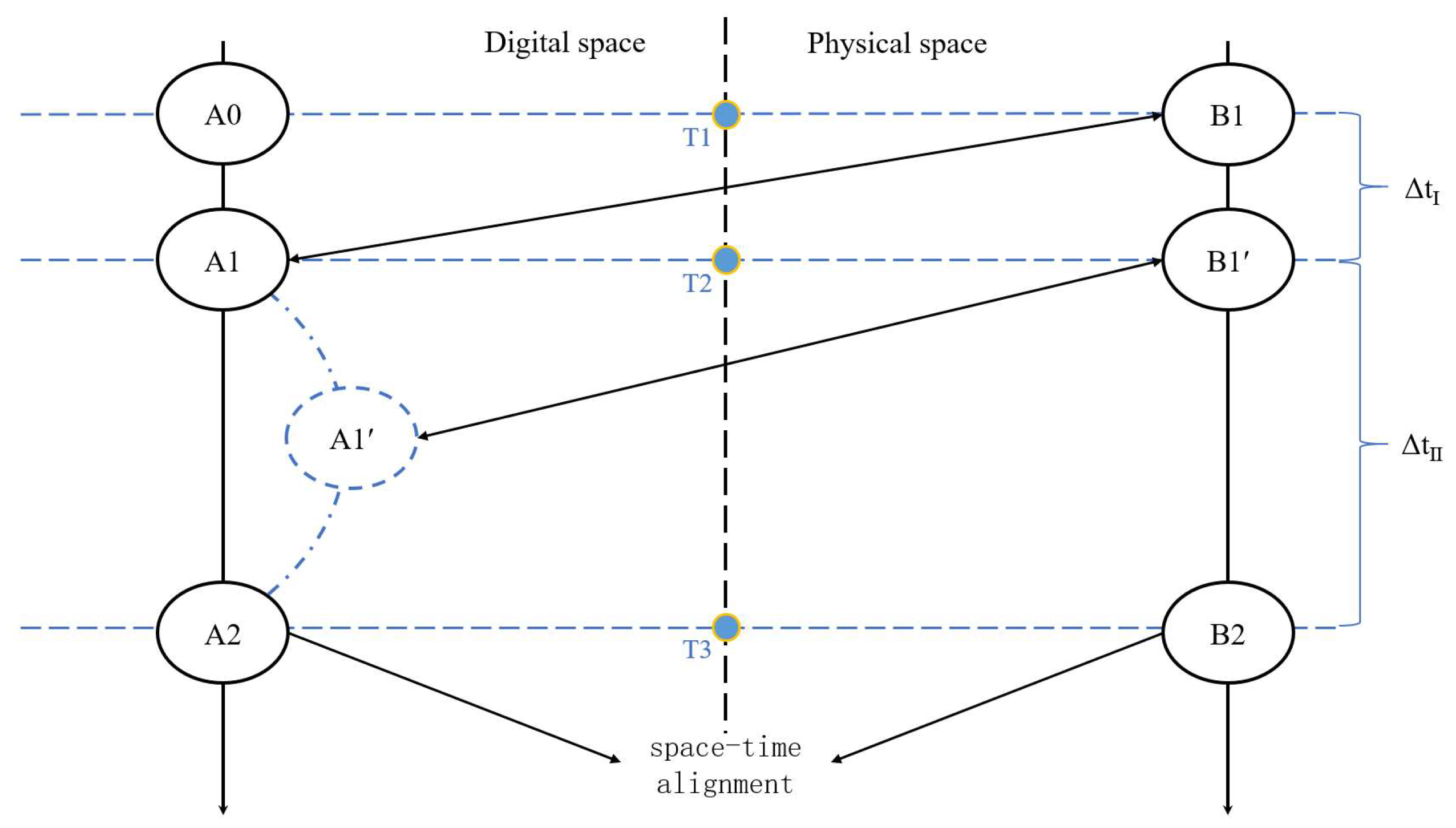
The leap process involves synchronization work in both spatial and temporal dimensions, including threshold synchronization and periodic synchronization. As shown in Figure 14, at the T1 moment, the physical spatial model executes a control instruction that is scheduled to perform a state change at the same time as the digital twin. However, the moment when the digital spatial model executes this instruction is not synchronized with the physical model due to the inherent time delay. The digital model completes the state change to A1 at the moment of T2, corresponding to the state of the physical model at the moment of T1 B. At this point, the digital space side is already behind ΔtⅠ compared to the time when the instruction was executed in the physical space, and the state of the physical model has transitioned to an intermediate state B1′.
In order to optimize the digital twin hysteresis problem caused by the inherent time delay, the digital model will predict the future state evolution of the physical model when the state change is performed at the T2 moment. The predicted state of the physical model will be changed to B2 at the moment of T3, and the digital model will take the predicted B2 as the goal of the state change, and take the moment of T3 as the endpoint of the change to carry out the state leap of the digital twin model. At this time, the digital model will no longer follow the state evolution route of the physical model via the intermediate state B1′, and the state of the object on one side of the digital space will be changed directly from A1 to A2 via ΔtⅡ.
After completing the leap, the bilateral spatial model state will reach a real sense of spatio-temporal synchronization at the T3 moment. By predicting and adjusting the state change target and time of the digital model, the effect of the inherent time delay on the digital twin lag can be effectively reduced, and more accurate spatio-temporal synchronization can be achieved.
Based on the state leap principle, threshold synchronization refers to the critical state B1′ that is reached at the moment of T2 if a side slip occurs in the body during the physical digging operation during the operation cycle. Once the sideslip exceeds the preset threshold, only adjusting the boring arm can no longer meet the operational requirements, and then a new disturbance event is considered to have occurred. The mapping relationship between the current event and the state is stored in the library and embedded into the state evolution network model. The physical operation must adjust the body parameters to return to the normal operation state. The state evolution path of the digital twin may deviate from the real digging site because the operation state experiencing the sudden perturbation is not in the original plan. In order to ensure the synchronization between reality and reality after a disturbance event, the corrective control commands of the physical tunneling operation need to be combined with the auxiliary guidance of the digital twin. Based on the current physical operation state, the digital twin predicts the future operation state of the physical object based on the corrective control instructions to carry out the super-prevolutionary state evolution, and adjusts the corrective control instructions appropriately according to the degree of compliance of the evolution results, and carries out the super-prevolutionary state evolution again. Through multiple cyclic leaps, the physical digging operation is finally brought back on track, realizing the temporal and spatial alignment of the bilateral space operation at the moment of T3.
Periodic synchronization, on the other hand, is to conduct a virtual-real consistency evaluation at the beginning of each intercept (an operation cycle) every time an operation instruction is issued, in order to enhance the reliability of virtual-real synchronization. By performing synchronization evaluation at the beginning of each operation cycle, possible deviations can be detected and corrected in time to ensure the consistency between reality and reality. This method helps to improve the accuracy and stability of the entire boring operation and reduce the risk of operational deviations due to disturbing events.

3. Experimental Eerification

3.1. Example of Application Based on Dynamic Modeling of The State Evolution of a Roadheader

Figure 15 shows the state evolution dynamics model feasibility validation experimental architecture, built to digging machine as the object of the physical platform, the use of Threejs and PyQt5 development of the host computer application to feed back the state of the physical platform, the interaction between the two information is analyzed and processed through the state evolution dynamics model.

3.2. Static Map Construction

According to the operation plan, predefined state nodes are embedded into the state evolution network. The initial state evolution network structure is constructed using Neo4j, as shown in Figure 16, and the values of the relevant parameters of the roadheader at each node are determined according to the planned truncation path in order to form static state nodes. During stable operation, the state evolution path will pass through each node from SA to SH in sequence.

3.3. Simulation and Analysis of Abnormal Events

Firstly, according to the anomalies of the fuselage position, they are categorized into four basic anomaly modes: fuselage slip, fuselage head-up, fuselage forward tilt and fuselage lateral tilt, and at the same time, they contain a variety of composite situations, and the anomalies that may occur in this phase are shown in Table 2.
It should be noted that the fuselage side tilt and slip cases have the possibility of anomalies occurring in two different directions, and the specific direction of attitude change will be derived from the data analysis.
The first step of the experiment will start with the simulation of anomalous events. As shown in Figure 17, the inertial guidance module can monitor the displacement and deflection of the fuselage in three axial directions, and the occurrence of the above abnormal events is simulated by directional interference of the inertial guidance module. Then a single abnormal event is used as the basis for analysis, and the composite event is split into several single events to be analyzed separately.
As an example, the analysis of the data taken after directional jamming of the inertial guidance is shown in Figure 18.
Figure 18 (a) shows the acceleration monitoring results of the three axes of the fuselage position, the Z-axis acceleration fluctuation indicates that the center of gravity of the fuselage is upward, and the X- and Y-axis acceleration fluctuation indicates that the fuselage is displaced in the X- and Y-axis directions. Figure 18(b) shows that the fuselage pitch angle changes from 0 degrees to -8 degrees, and the change of the absolute angle value of the pitch angle to a negative value can be obtained that the fuselage is tilted forward, and if the value of the absolute angle value changes in the opposite direction, it means that the fuselage lifts its head; the yaw angle of the fuselage changes from about 9 degrees to 16 degrees, and according to the direction of the change of the value of the absolute angle value, it can be obtained that the fuselage slips clockwise, and if the value of the absolute angle value changes in the opposite direction, it means that the fuselage slips in the opposite direction. If the absolute angle value changes in the opposite direction, it means that the fuselage slips in the counterclockwise direction; the roll angle of the fuselage changes from 0 degrees to 3 degrees, according to the direction of its absolute angle value changes, it can be concluded that the fuselage has a right tilt phenomenon, if the absolute angle value changes in the opposite direction, it means that the fuselage has a left tilt.
Therefore, the fuselage position situation after experiencing the current anomalous event can be obtained as shown in Figure 19, and the type of anomalous event is tilting right and forward during clockwise slip.
According to the same analysis method can be obtained to appeal all the abnormal events are analyzed as shown in Figure 20.

3.4. Abnormal Event Recognition Algorithm

The analysis of the data is all carried out by the event recognition algorithm, and the basic content of the event recognition algorithm is the identification of abnormal changes in the airframe position state data and the judgment of the abnormal threshold value.
(1) Abnormal Status Recognition
As shown in Figure 21, aimCode represents the control command event check code of the fuselage under the current time stamp, currentCode represents the current experience event check code, i.e. 001110, and checkCode represents the abnormal event check result. According to the event check result, it can be known that the current abnormal event causes the fuselage to be displaced in these two axes, and the fuselage heading angle is also shifted. Accordingly, the type of the abnormal event can be determined and the state evolution network can be dynamically updated. the SNew node represents the newly generated abnormal event state node, while the SMid node represents the state node that the fuselage should be in according to the plan at the time of perturbation. Once a perturbation event is detected on the airframe, operations will be suspended and SNew can be seen as instantaneously generated, while SMid is the target state node for airframe attitude correction.
(2) Abnormal degree judgment
Take a separate fuselage slip event as an example, the yaw angle of the fuselage changes after the slip, in order to satisfy the cut-off quality, in addition to the fuselage position as well as the slewing of the cut-off arm with the basic logic of the algorithm is shown in Figure 22.
As shown in Figure 23, first determine the relationship between cylinder expansion and angle change, θ is the angle between the straight line where the cylinder is located and the straight line where the center of rotation and the rear end of the cylinder on that side are located, and α is the angle between the radius of rotation where the cylinder on this side is located at the fixed point of the rotary platform and the straight line where the center of rotation is located and where the rear end of the cylinder on that side is located.
The variation of both θ and α with respect to cylinder expansion and contraction is as follows:
θ = cos 1 c + v t 2 + B 2 2 C 2 2 B c + v t
α = cos 1 B 2 + C 2 c + v t 2 2 B C
Then determine the relationship between the change of the pointing angle of the cutting arm, σ is the angle between the cutting arm and the coal arm, and set the initial operation, i.e., the cutting head is in the state SA when the angle is σ0, the target cutting width of the roadway is 2L, and the initial length of the cutting arm is S0, so that the relationship can be obtained:
δ = 90 + α β
L = cos δ 0 · S 0
Take the slewing center O of the rotary platform as the origin, and get the coordinates of the horizontal left endpoint PL and the right endpoint PR of the roadway interface in the Z-direction projection:
P L : S 0 · cos δ 0 ,   S 0 · sin δ 0
P R : S 0 · cos δ 0 ,   S 0 · sin δ 0
The cutting arm length required to meet the effective cutting in the current situation is calculated by setting the slewing center of the rotary platform to slip from O to O′ after the fuselage slip, Smax is the maximum length of the cutting arm required, at the moment when the slip occurs, the default slewing angle of the rotary platform is 0 (the slewing angle can also be calculated based on the timestamp acquisition to derive the result of the slip), and x, y are the relative displacements of the fuselage in the X, Y coordinate direction at the present time of the slip. x, y is the relative displacement of the current fuselage slip in the X, Y coordinate direction.
Combining PL and PR based on the coordinates of the origin O, can be obtained:
S m a x = S 0 · sin δ 0 + y 2 + S 0 · cos δ 0 + x 2
Substitute:
S m a x = c · sin π 2 + cos 1 B 2 + C 2 2 c + v t 2 2 B C β + y 2 + c · cos π 2 + cos 1 B 2 + C 2 2 c + v t 2 2 B C β + x 2
If the maximum required cutting arm length has exceeded the fixed length of the cutting arm of the fuselage that satisfies the safe cutting, it means that an abnormality has occurred in the current fuselage position, and the slip event experienced by the current fuselage can be regarded as a perturbation event.

3.5. Dynamic Mapping Update

When an anomaly occurs during state evolution, the anomaly state type code is matched against known perturbation states in the database. If a match is found, it is processed according to the historical scheme; if the same type of event is not found, a new state node is created in the state evolution network and a new event state is established to record the perturbation event into the database. Figure 16 demonstrates that the initial state evolution network generates new state nodes after experiencing a fuselage offset event, and the updated state evolution network structure is shown in Figure 24. In the transition from state SA to state SB, different anomalous events cause different perturbation state branches. The blue nodes connected by the red STABLE relationship are the initial state evolution network, i.e., the planned state evolution path, and the orange state node SMid is the last state node on the planned path before downtime, from which the abnormal state evolution crosses over to the unplanned evolution path. Red state nodes such as Shy, StthY and SttCqHy are newly generated anomalous event state nodes, and successful node generation implies that the event state has been deposited into the historical event repository of the event state model.
While dynamically updating the anomalous event state node in the state evolution network, the event state model will formulate and execute the fuselage attitude correction strategy based on the current fuselage position parameters with SMid as the target state node to ensure the quality of the subsequent cutoff operation. The evolutionary relationship STABLE from SNew to SMid is consistent with that of the conventional state evolution path, demonstrating the effectiveness of the state regression scheme after the correction of the abnormal state.
Figure 25 shows the constructed event state monitoring upper platform, which can monitor the changes of various parameters of the roadheader, the dynamics of the state evolution network, and the log records of the execution of control commands in real time, and in this case, it can provide visual feedback on the processing and processing results of the state evolution dynamics model after a perturbation event.

4. Results and Reflections

In this study, the monitoring, receiving and processing of the body position parameters, the operation of the abnormal event recognition algorithm and the abnormal event type recognition algorithm, and the dynamic update of the tunneling state evolution network are accomplished from the simulation of abnormal body disturbance events and the recognition and processing of abnormal events. The results of this case validate the feasibility of the state evolution dynamics model proposed in this paper, but there are also many limitations.
The shortcoming is that the model's current scope of application is mainly limited to the digging operation within a single section, and the adaptability and long-term stability of the model for the long-cycle operation of multiple sections still need to be further researched and verified. Future research will be devoted to expanding the applicability of the model, especially in complex and variable long-cycle roadheading operations, by improving the adaptive conditions of the model and optimizing the operation modes, so as to enhance the stability and robustness of the model. This will bring more innovation and value to the field of remote intelligent roadheading and promote the development of roadheading technology to a higher level.

4.1. Limitations Reflection

(1) Strong single-intercept scenario dependence: the model performs well in single-intercept operations, but the state evolution network complexity grows exponentially in long-period multiple-intercept scenarios, leading to an increase in computational resource consumption and a decrease in real-time performance.
(2) Insufficient algorithm robustness: the classification accuracy of the anomaly identification algorithm for composite perturbations (e.g., slip + sideways tilt + forward tilt) is low, and needs to be combined with machine learning to optimize the feature extraction logic.
(3) Simplified experimental scenarios: the current experiments only simulate a single model (cantilever roadheader) and a fixed roadway cross-section, and do not cover the full cross-section roadheader (TBM) or complex geological conditions.

4.2. Improvement Direction

(1) Introducing a lightweight model: Adopting federated learning or edge computing technology to distribute the state evolution network to multiple computing nodes to reduce the computational load of the multi-section scenario.
(2) Fusion of multi-source data: Combine geo-radar and inertial navigation data to enhance the prediction ability of disturbance events and reduce the proportion of passive response.
(3) Extended application validation: Cooperate with coal mining enterprises to deploy the model in real digging face to verify its applicability in extreme working conditions such as gas protrusion and surrounding rock fragmentation.

5. Conclusions

The state evolution dynamics model constructed in this paper relies on the event-triggered mechanism to effectively cope with the state fluctuations triggered by abnormal perturbations in remote intelligent tunneling, and realizes rapid response and accurate correction. The embedded state jumping mechanism greatly improves the real-time interaction between reality and reality of the digital twin model, injects strong power for event-driven tunneling operation, and significantly improves its efficiency and accuracy. As verified by the experimental cases, the model shows good feasibility in the endogenous evolution of state dynamics and event-driven remote intelligent roadheading mode, which provides a strong support for the intelligent development of roadheading workface and the main conclusions are as follows:
(1) Theoretical innovation: through the discretization of the positional state and the construction of the dynamic map, the event-driven mechanism is combined with the digital twin technology for the first time, which solves the defects of static mapping and passive response in the traditional model.
(2) Technological breakthrough: the state leaping mechanism can improve the accuracy of virtual and real synchronization through the over-advanced state prediction and threshold synchronization strategy, which provides a high real-time control basis for remote intelligent digging.
(3) Application value: the experiment verifies the effectiveness of the model in abnormal event identification, dynamic map updating and closed-loop control, which provides a landable technical solution for the research and development of intelligent roadheading equipment in coal mines.
However, the adaptability of the model in multi-intercept long-cycle operation still needs to be optimized. Future research will focus on breakthroughs in complex disturbance classification algorithms, distributed computing architecture design, and explore the deep integration with 5G + industrial Internet platform, to promote the leapfrog development of roadheading equipment from “single machine intelligence” to “group collaboration”.

References

  1. WANG Guofa, REN Huaiwei, ZHAO Guorui, DU Yibo, PANG Yihui, XU Yajun, ZHANG Desheng. Analysis and countermeasures of ten 'pain points' of intelligent coal mine[J]. Journal of Mine Automation, 2021, 47(6): 1-11. [CrossRef]
  2. ZHANG Xuhui, YANG Wenjuan, XUE Xusheng, et al. Challenges and developing of the intelligent remote controlon roadheaders in coal mine[J]. Journal of China Coal Society, 2022, 47(1): 579-597.
  3. Hu Yong. Mining roadheader slewing bearing failure analysis and preventive measures [J]. Journal of Coal mining machinery,2021,42(07):184-186. [CrossRef]
  4. Industry application of digital twin: from concept to implementation.
  5. Semeraro, C.; Lezoche, M.; Panetto, H.; Dassisti, M. Digital twin paradigm: A systematic literature review. COMPUT IND 2021, 130, 103469. [Google Scholar] [CrossRef]
  6. Jones, D.; Snider, C.; Nassehi, A.; Yon, J.; Hicks, B. Characterising the Digital Twin: A systematic literature review. CIRP J MANUF SCI TEC 2020, 29, 36–52. [Google Scholar] [CrossRef]
  7. Zhou, Y.; Fu, Z.; Zhang, J.; Li, W.; Gao, C. A Digital Twin-Based Operation Status Monitoring System for Port Cranes. SENSORS-BASEL 2022, 22. [Google Scholar] [CrossRef] [PubMed]
  8. Rosen, R.; von Wichert, G.; Lo, G.; Bettenhausen, K.D. About The Importance of Autonomy and Digital Twins for the Future of Manufacturing. IFAC-PapersOnLine 2015, 48, 567–572. [Google Scholar] [CrossRef]
  9. Schluse, M.; Priggemeyer, M.; Atorf, L.; Rossmann, J. Experimentable Digital Twins—Streamlining Simulation-Based Systems Engineering for Industry 4.0. IEEE T IND INFORM 2018, 14, 1722–1731. [Google Scholar] [CrossRef]
  10. Kuenzel, M.; Kraus, T.; Straub, S. In Collaborative Engineering - Main features and challenges of cross-company collaboration in engineering of products and services, 2019, 2019; IEEE: 2019; pp. 1-7.
  11. Fei, T.; et al. Five-dimension digital twin model and its ten applications. Computer Integrated Manufacturing Systems 2019, 25, 1–18. [Google Scholar]
  12. FEI-YUE WANG. Parallel control and digital twins:control theory revisited and reshaped. [J]. Chinese journal of intelligent science and technology, 2020, 2(3): 293-300. [CrossRef]
  13. WANG Fei-Yue. Parallel Control: A Method for Data-Driven and Computational Control. ACTA AUTOMATICA SINICA, 2013, 39(4): 293-302. [CrossRef]
  14. Z. Jun; X.U. Pei-Dong; W. Fei-Yue Parallel Systems and Digital Twins: A Data-driven Mathematical Representation and Computational Framework. Acta Automatica Sinica 2020, 46, 1346-1356.
  15. T. Fei; M.A. Xin; Q.I. Qinglin; L. Weiran; Z. He; Z. Chenyuan Theory and key technologies of digital twin connection and interaction. Computer Integrated Manufacturing Systems 2023, 29, 1-10.
  16. Amanda, L.; John, V.; Mrinal, K. Multiresolution state-space discretization for Q-Learning with pseudorandomized discretization. Journal of Control Theory and Applications 2011, 9, 431–439. [Google Scholar]
  17. L Yinghui.Development of experimental bench for cutting section of digital twin cantilever type roadheader based on similarity theory[D]. Anhui University of Science and Technology,2023. [CrossRef]
  18. Lin Zijie , Lu Guoping , Lv Wang , Wu Baolin. Adaptive Event-Triggered Control for Spacecraft Attitude Tracking[J]. Aerospace Control, 2021, 39(1): 32-39.
  19. Santos C H, D.Q.J.A. Use of simulation in the industry 4.0 context: Creation of a Digital Twin to optimise decision making on non-automated process. J SIMUL 2022.
  20. Karakra A, F.F.L.E. A discrete event simulation-based methodology for building a digital twin of patient pathways in the hospital for near real- time monitoring and predictive simulation. Digital Twin 2022. [Google Scholar] [CrossRef]
  21. Cubukcuoglu, C.; Nourian, P.; Sariyildiz, I.S.; Tasgetiren, M.F. A discrete event simulation procedure for validating programs of requirements: The case of hospital space planning. SOFTWAREX 2020, 12, 100539. [Google Scholar] [CrossRef]
Figure 1. Dynamic model of equipment state evolution in excavation face.
Preprints 149947 g001
Figure 2. Schematic of state discretization.
Preprints 149947 g002
Figure 3. Planned Operational State Evolution Network.
Preprints 149947 g003
Figure 4. Body slippage.
Preprints 149947 g004
Figure 5. State Branches.
Preprints 149947 g005
Figure 6. Closed-loop state evolution network.
Preprints 149947 g006
Figure 7. Key Event Status Schematic.
Preprints 149947 g007
Figure 8. Schematic diagram of the classification of event types.
Preprints 149947 g008
Figure 9. Schematic diagram of classification and hierarchical storage.
Preprints 149947 g009
Figure 10. Flow chart of disturbance recognition algorithm.
Preprints 149947 g010
Figure 11. Disturbance Event Recognition Flowchart.
Preprints 149947 g011
Figure 12. Real-time data acquisition.
Preprints 149947 g012
Figure 13. Disturbance Event Information Flowchart.
Preprints 149947 g013
Figure 14. State Jump Schematic.
Preprints 149947 g014
Figure 15. Experimental Architecture.
Preprints 149947 g015
Figure 16. Static graph construction.
Preprints 149947 g016
Figure 17. data acquisition.
Preprints 149947 g017
Figure 18. Trend of changes in body parameters.
Preprints 149947 g018
Figure 19. Scene simulation of tilting and leaning forward during sliding.
Preprints 149947 g019
Figure 20. Analysis of abnormal event scenarios.
Preprints 149947 g020
Figure 21. The process of generating abnormal states triggered by status identification codes.
Preprints 149947 g021
Figure 22. Abnormal event detection algorithm based on the maximum required elongation of the cutting arm.
Preprints 149947 g022
Figure 23. Maximum cutting arm elongation algorithm required after sliding.
Preprints 149947 g023
Figure 24. State evolution network dynamic update.
Preprints 149947 g024
Figure 25. Event Status Monitoring Platform.
Preprints 149947 g025
Table 1. Roadheader status parameters.
Timestamp Slalom Raise L&S Space Coordinate Divergence Pitch Roll
Parameters T α γ e X Y Z H P B
Table 2. Abnormal event type.
single event composite event Multiple composite events
slippage(s) Slippage & lean rise head & slippage & lean
Lean(l) Slippage & rise head lean forward & slippage & lean
rise head(rh) Slippage & lean forward
lean forward(lf) Lean & rise head
Lean & lean forward
Disclaimer/Publisher’s Note: The statements, opinions and data contained in all publications are solely those of the individual author(s) and contributor(s) and not of MDPI and/or the editor(s). MDPI and/or the editor(s) disclaim responsibility for any injury to people or property resulting from any ideas, methods, instructions or products referred to in the content.
Copyright: This open access article is published under a Creative Commons CC BY 4.0 license, which permit the free download, distribution, and reuse, provided that the author and preprint are cited in any reuse.
Prerpints.org logo

Preprints.org is a free preprint server supported by MDPI in Basel, Switzerland.

Subscribe

Disclaimer

Terms of Use

Privacy Policy

Privacy Settings

© 2025 MDPI (Basel, Switzerland) unless otherwise stated