Submitted:
18 February 2025
Posted:
18 February 2025
You are already at the latest version
Abstract
With the expansion of power system scale and the advancement of new energy grid integration, the performance verification of medium and high-voltage power equipment faces increasingly stringent requirements. This paper addresses the issues of low efficiency, poor reproducibility, and safety hazards in traditional large-scale testing by proposing a system model for a high-capacity test system and a measurement and control system solution based on power system power sources. By establishing simulation models of the main test circuits, the paper analyzes the short-circuit currents and Transient Recovery Voltage (TRV) waveforms of high-voltage switchgear and introduces a standardized method for configuring test circuits. This method has been validated through simulations and physical tests, demonstrating its feasibility and accuracy. Based on this, a standardized method for test circuits is proposed, and its feasibility is verified through practical testing. Additionally, an automated monitoring and control system is designed to streamline the testing process, reduce human intervention, and ensure the accuracy of test data, achieving full-process automation in test parameter selection, circuit connection, and data acquisition. This system significantly enhances testing efficiency, safety, and consistency, effectively improving the efficiency and reliability of inspections and testing for medium and high-voltage power equipment.
Keywords:
1. Introduction
- A standardized methodology for test circuit design;
- A ring network topology for test monitoring and control;
- Systematic solutions for test data acquisition, signal monitoring, and control schemes;
- Optimized procedures for high-capacity short-circuit testing.
2. Power Network-Based High-Capacity Test Circuit Design
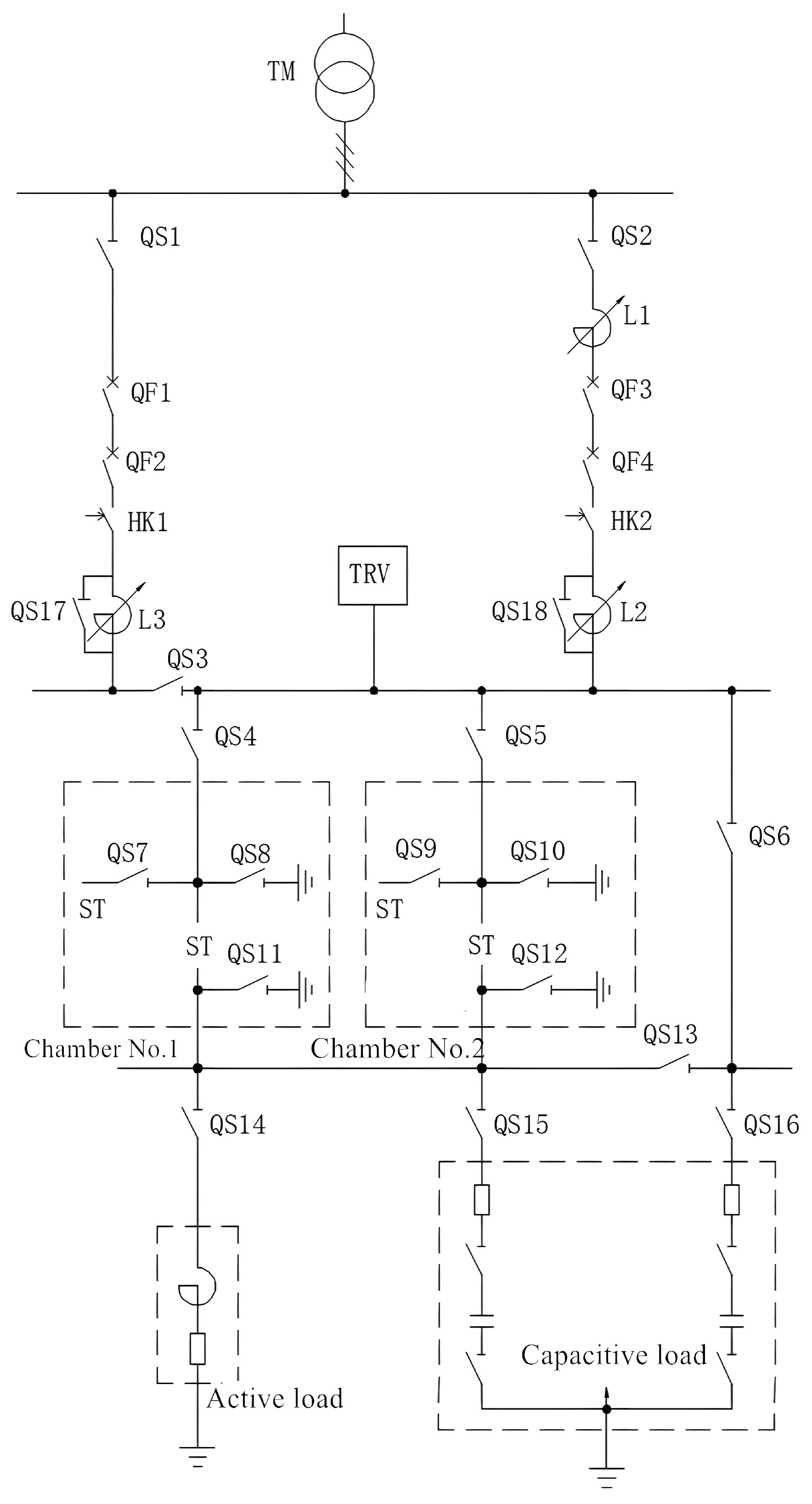
2.1. Main Test Circuit Architecture
2.1.1. Dual-Voltage Test Circuit Configuration (12kV/40.5kV)
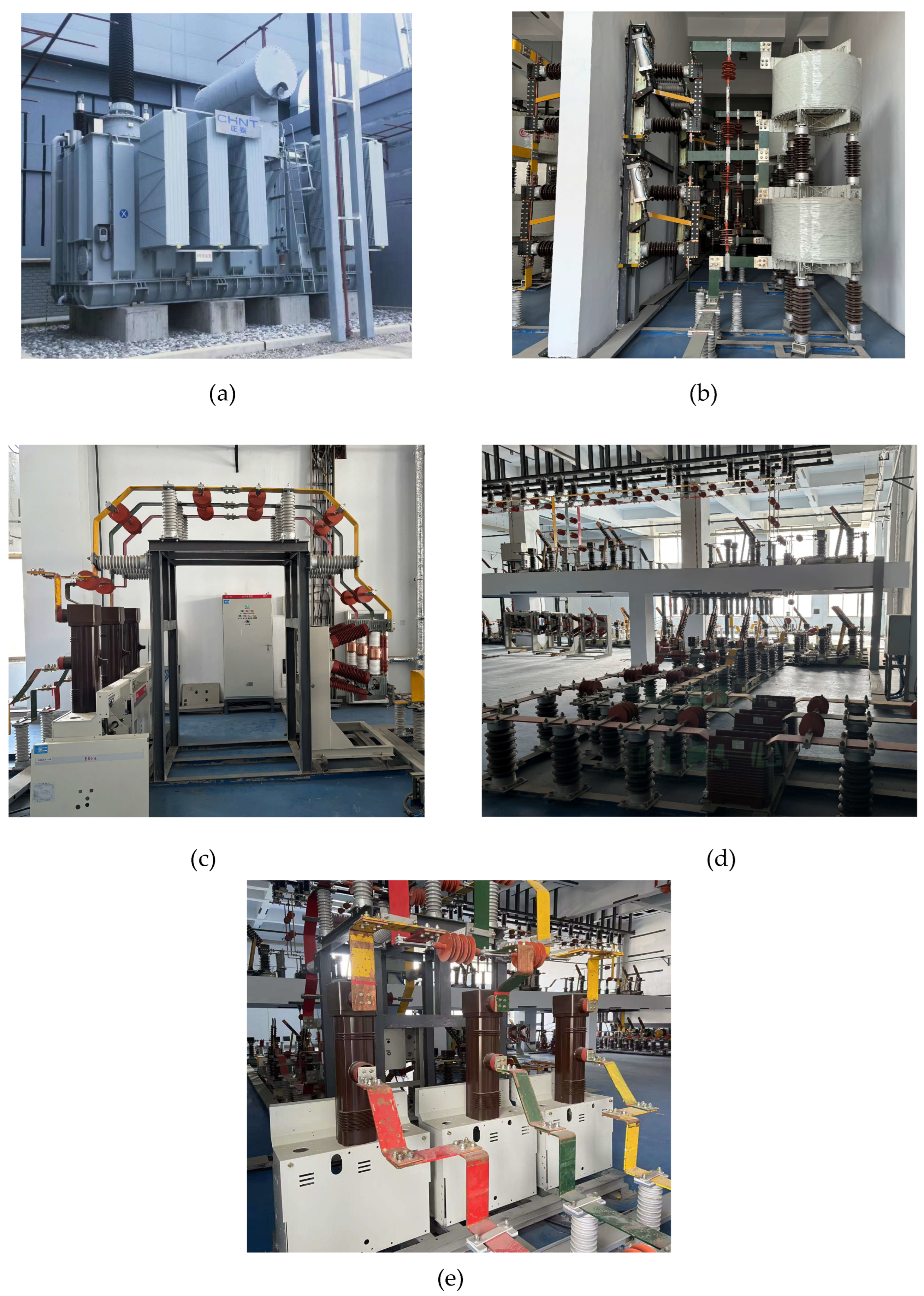
- Short-circuit transformer (TM), see Figure 2(a)
- Busbar system, see Figure 2(c) and (d)
- Disconnecting switch (QS1), see Figure 2(b) and (d)
- Protective circuit breaker (QF1), see Figure 2(c)
- Operating circuit breaker (QF2), see Figure 2(c)
- Phase-selection switch (HK1), see Figure 2(e)
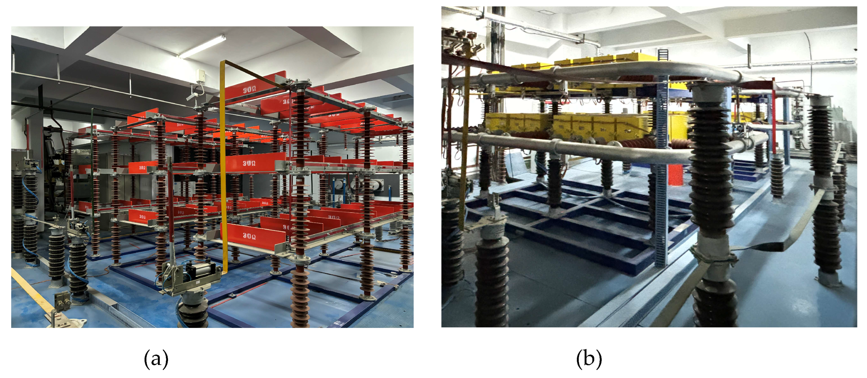
- Adjustable reactor (L3), see Figure 2(b)
- Three-phase short-circuit capacity of 330 kV busbar: 7,111 MVA
- Short-circuit transformer: Composed of three single-phase transformers, with specific parameters detailed in Table 1.
- Short-circuit transformer (TM)
- Busbar system
- Disconnecting switch (QS2)
- Current-limiting reactor (L1)
- Protective circuit breaker (QF3)
- Operating circuit breaker (QF4)
- Phase-selection switch (HK2)
- Adjustable reactor (L2)
2.1.2. Active Load and Capacitive Load
- Load switches
- Fuses
- AC contactors
- Two 40.5 kV back-to-back capacitor banks
- Continuous current rating: 1–1000 A
- High-voltage AC circuit breakers
- High-voltage AC load switches
- Applicable test parameters:
- Rated voltage range: 3.6–40.5 kV
- Capacitive current range: 1–1000 A.
2.1.3. TRV Equipment
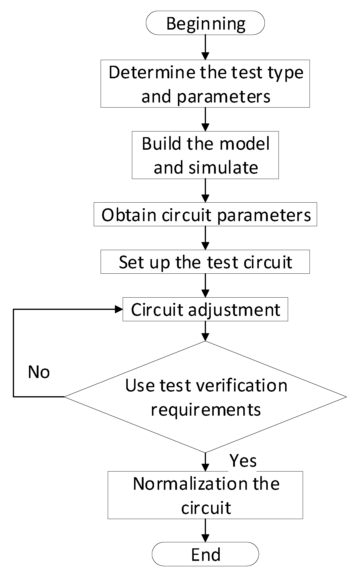
2.2. Standardization of Test Circuits
- Traditional tests rely on manual configuration of circuit parameters (such as impedance, TRV waveform, etc.), and operational differences often lead to inconsistent results. Standardization solves these problems through a predefined parameter library (Figure 4), enabling automated configuration.
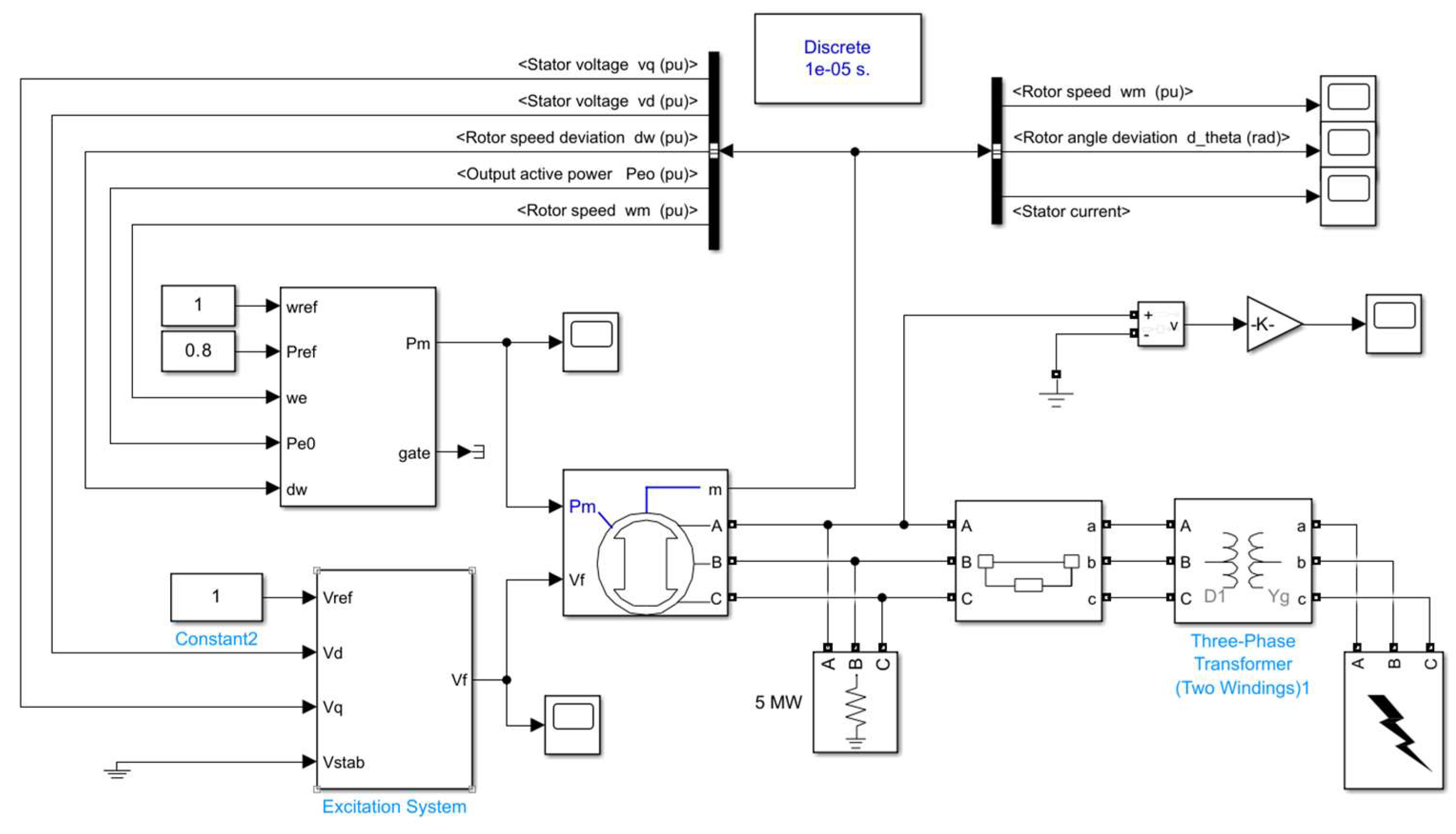
- The construction of the standardized circuit library adopts a dual approach combining simulation modeling and experimental verification (Figure 2). Key parameters (such as voltage, current, source/load impedance, TRV parameters, etc.) are obtained through MATLAB/Simulink simulation. Then, these results are verified through a physical test circuit, and the parameters are fine-tuned according to the measurement data. Finally, standardized circuit templates are established and stored. This library supports multiple test types (such as T60, T100a) and voltage levels (from 12kV to 40.5kV).
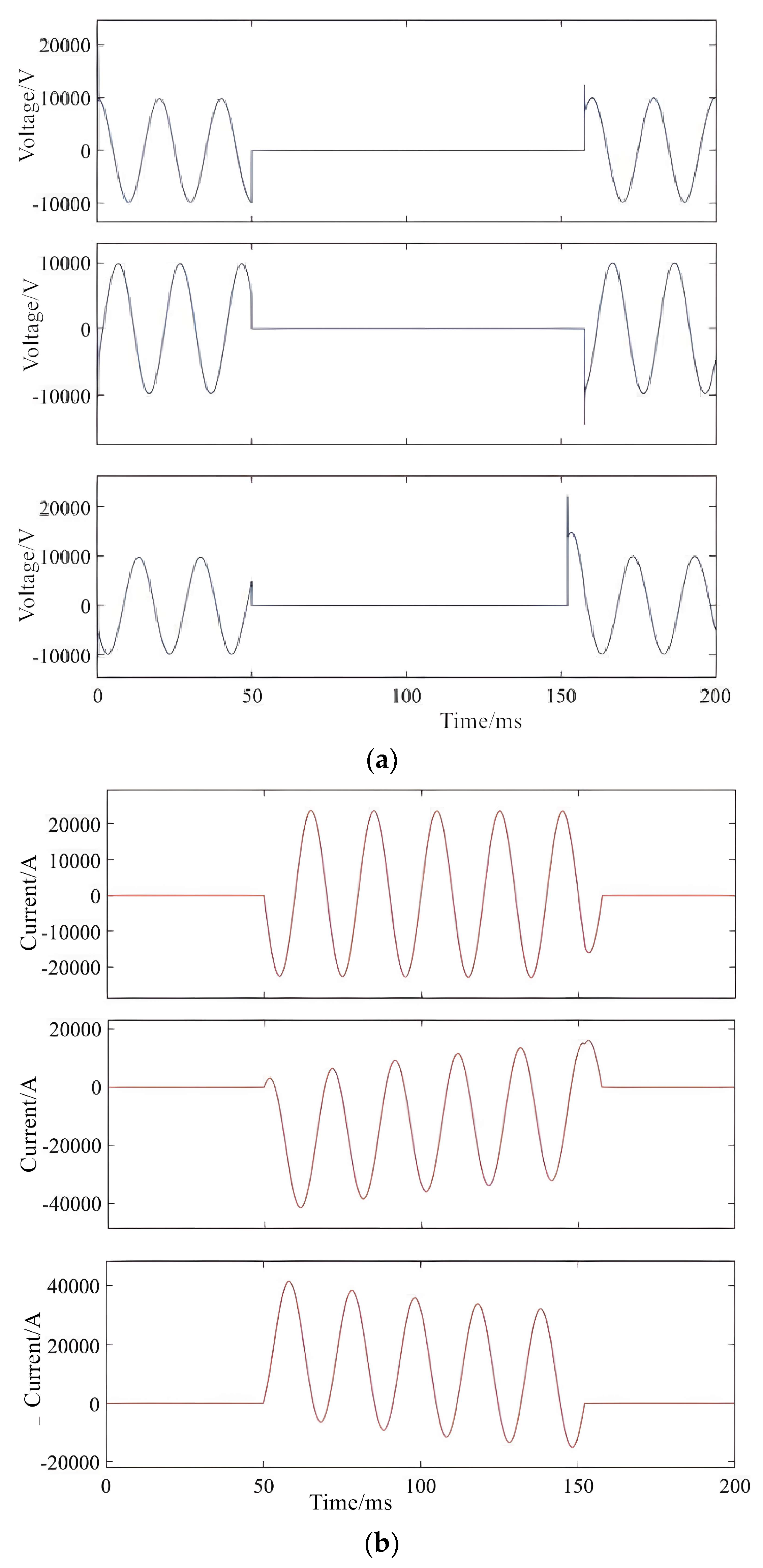
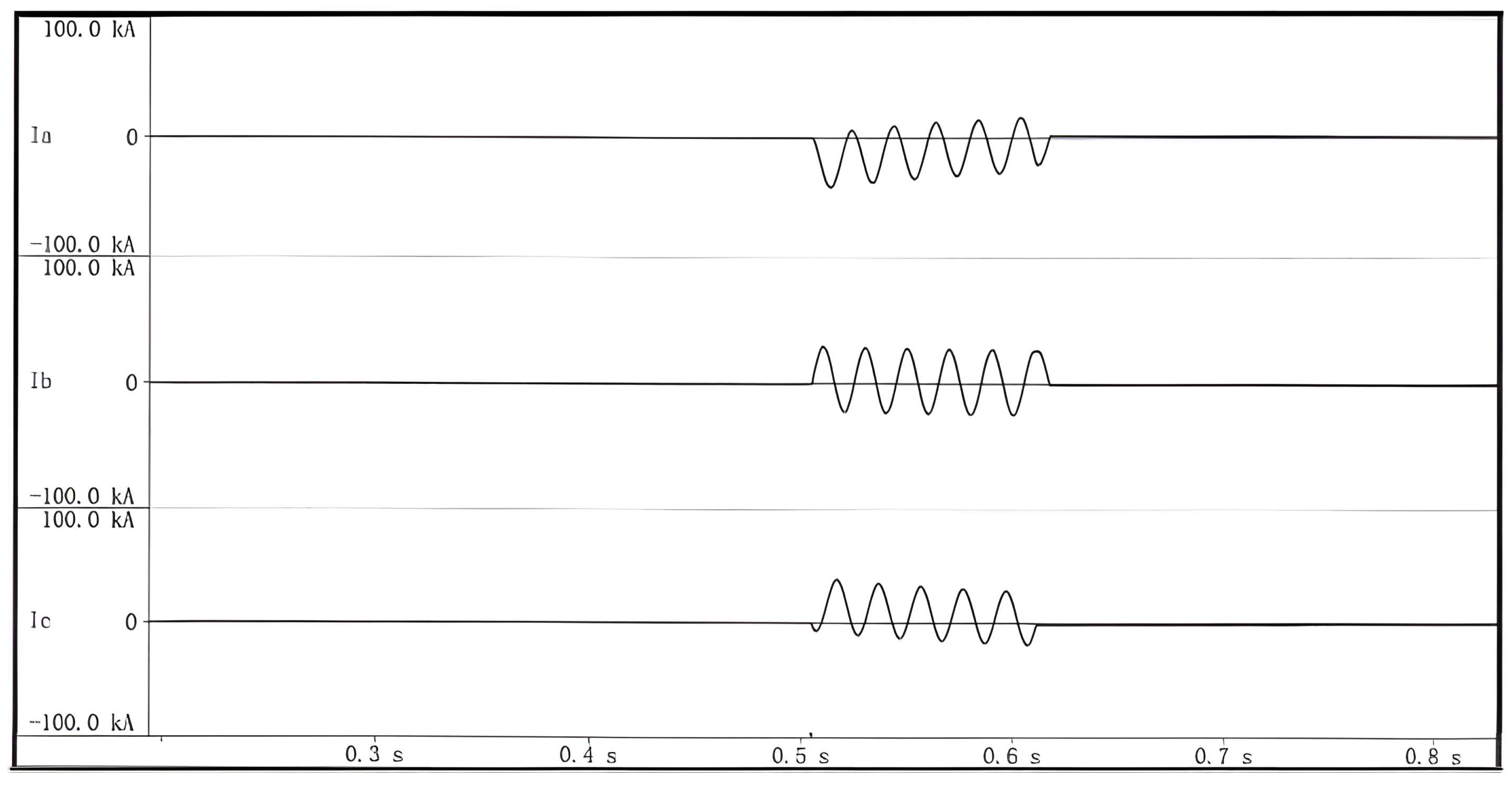
2.2.1. Simulation
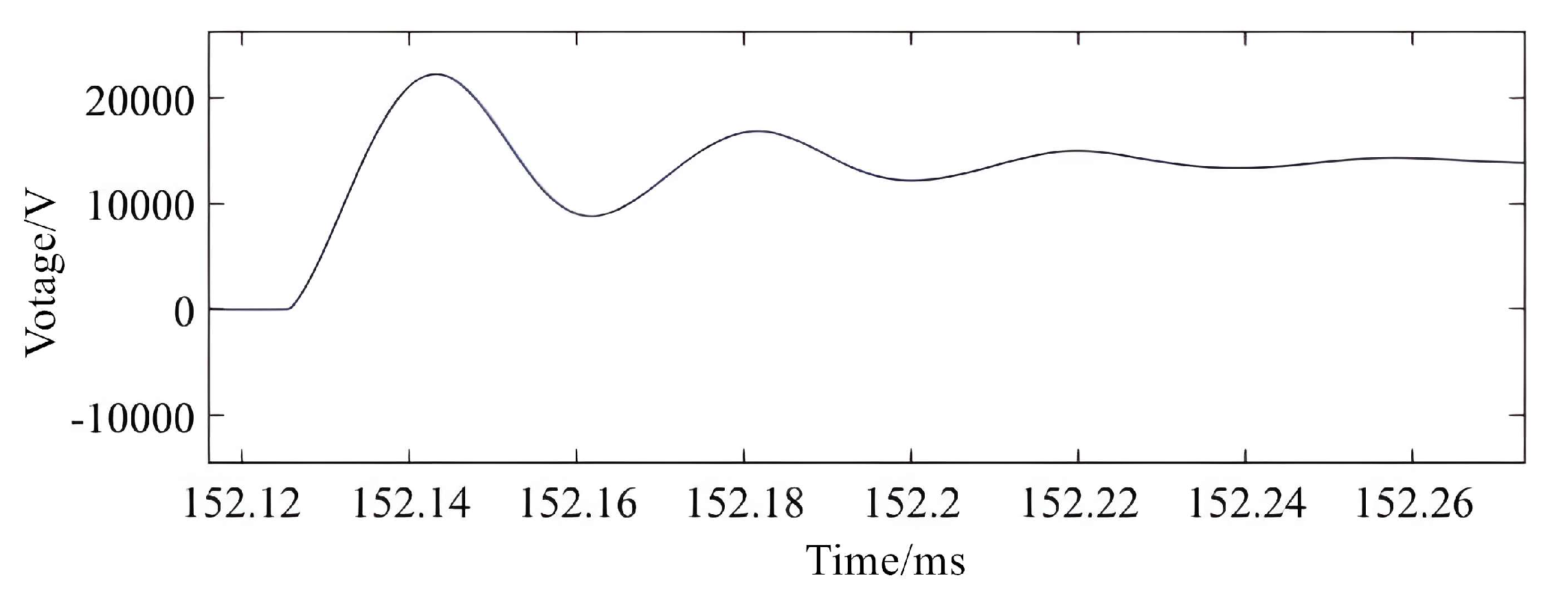
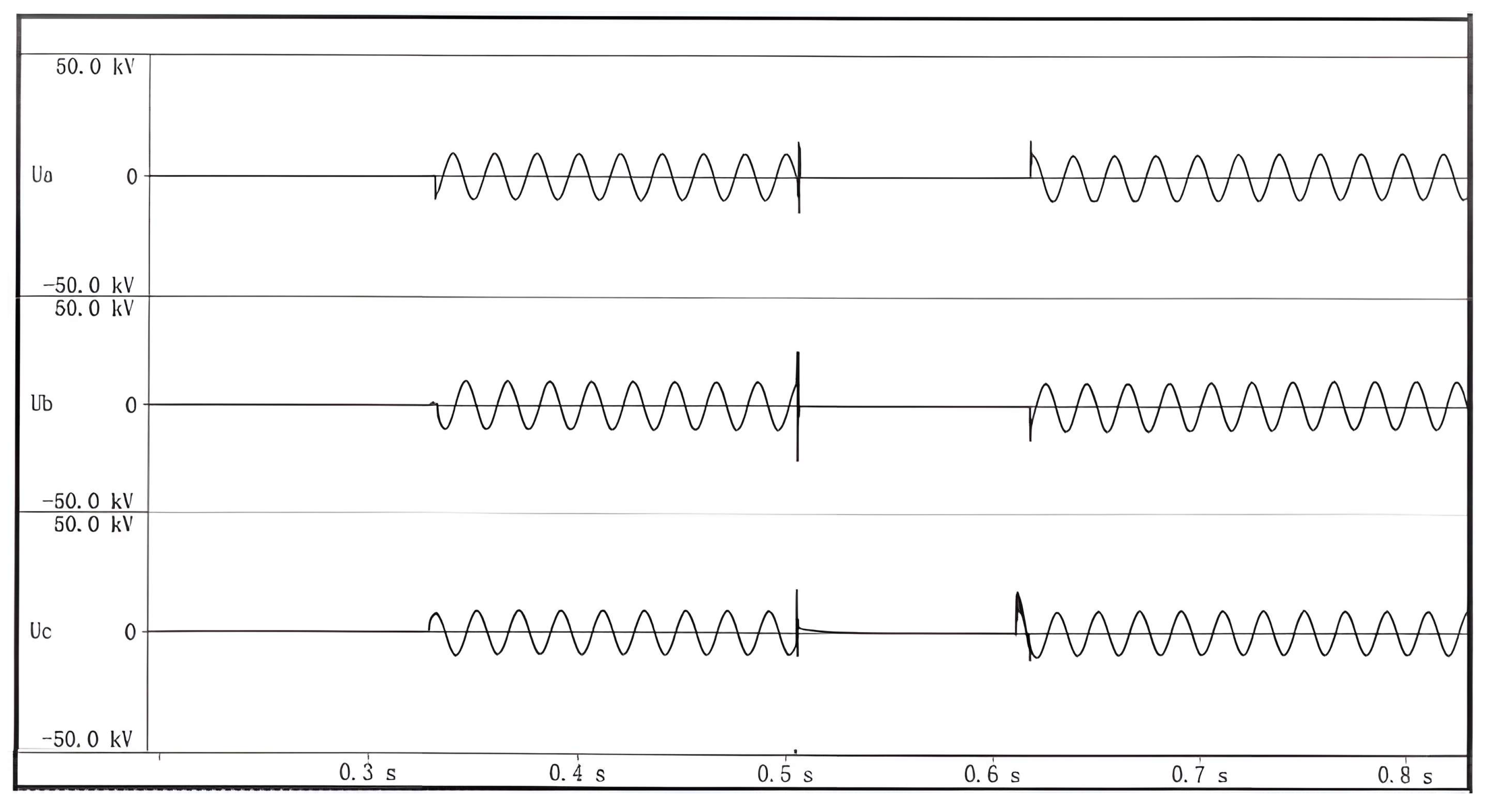
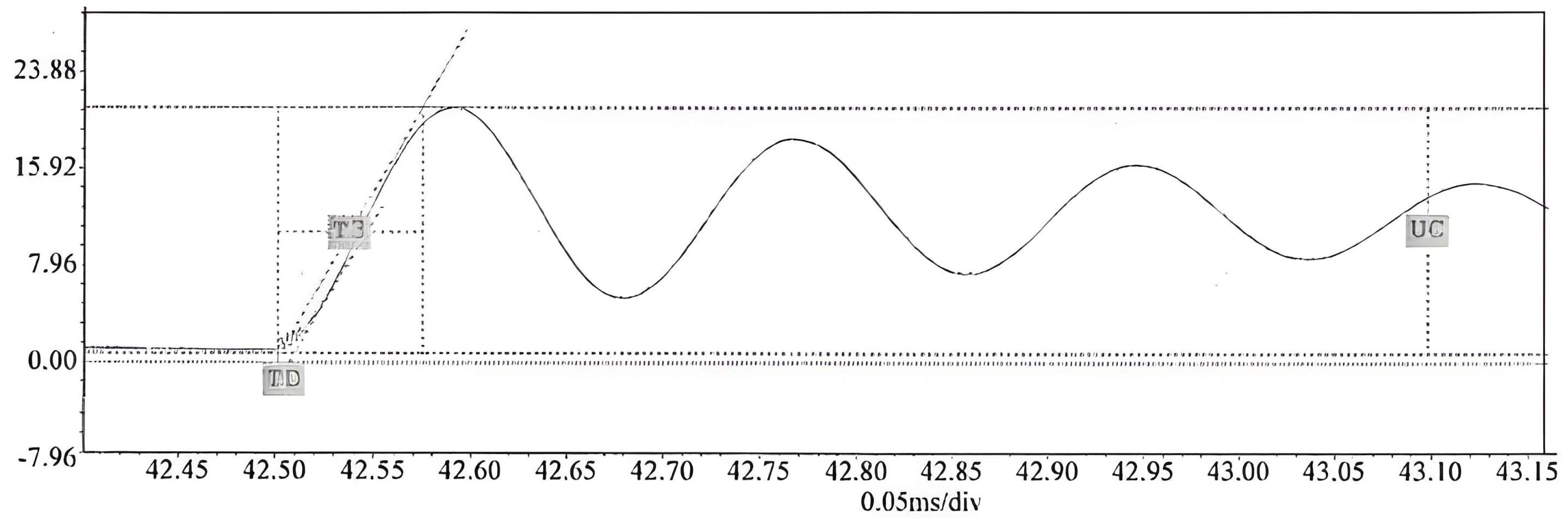
2.2.2. Simulation Result Verification
2.2.3. Comparison and Discussion
3. Test Data Acquisition and Monitoring Control System
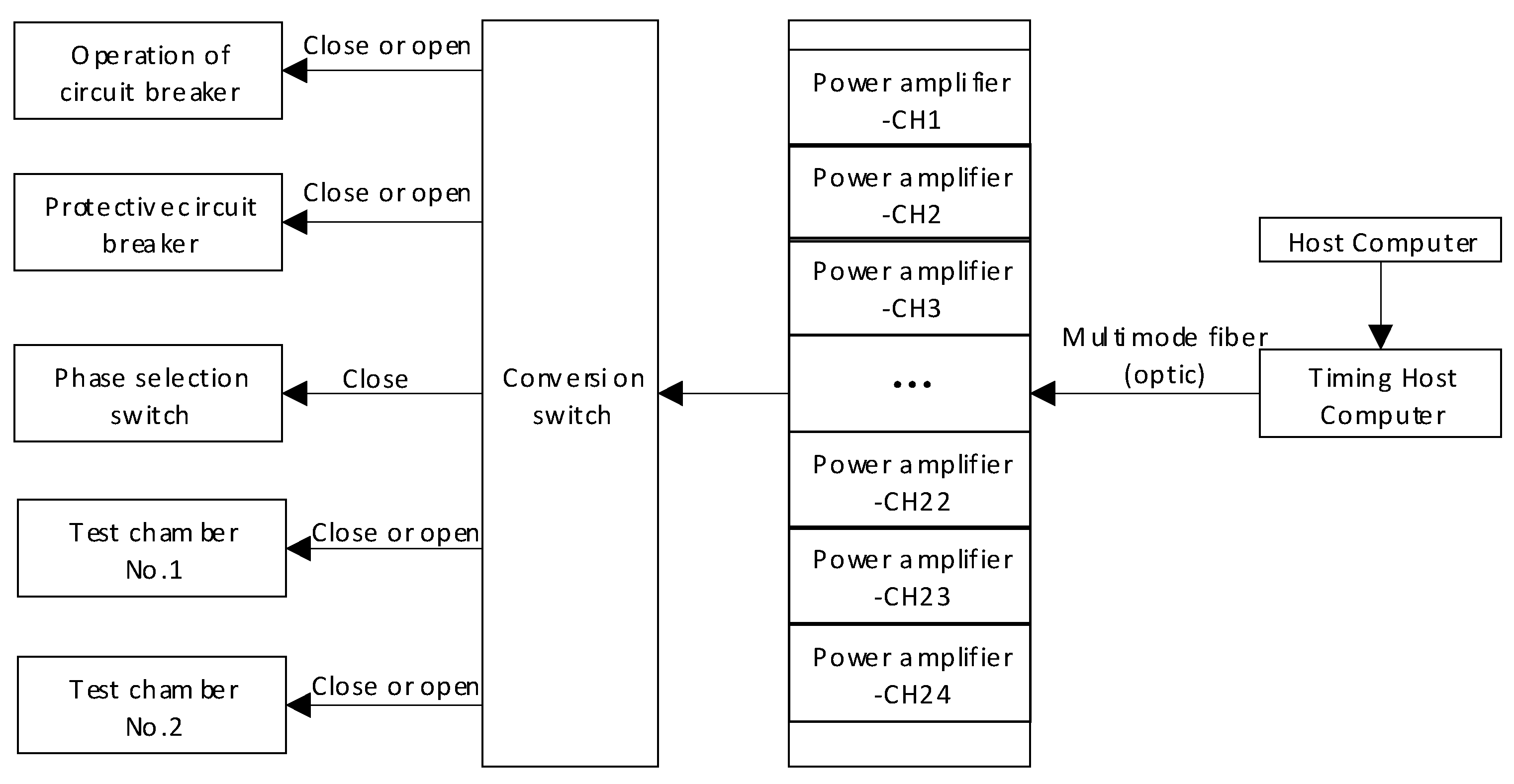
3.1. Secondary Monitoring and Control Scheme
3.1.1. Test Circuit Connection Control
3.1.2. Secondary Signal Monitoring and Control
3.1.3. Sequential Control
3.1.4. TRV Device Monitoring and Control
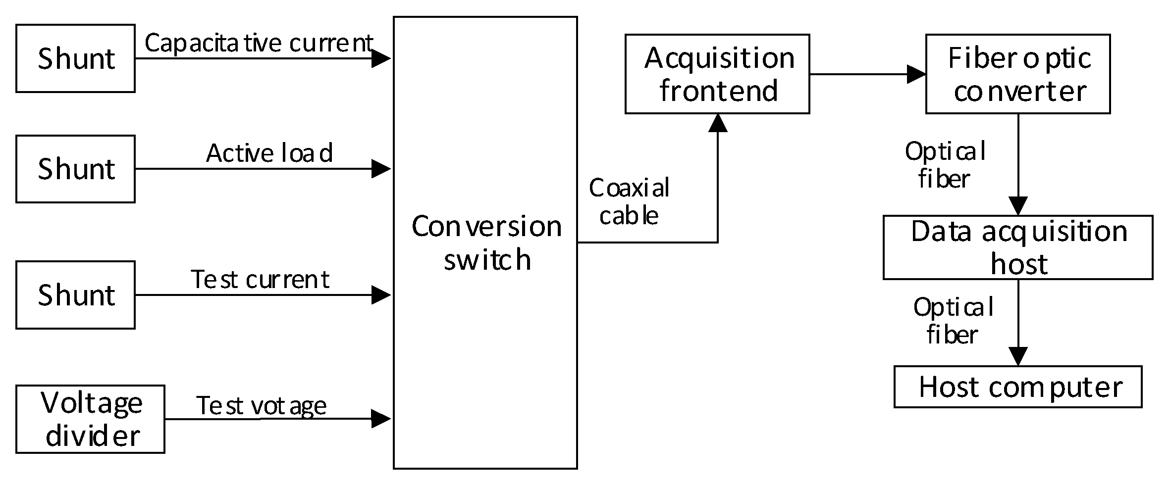
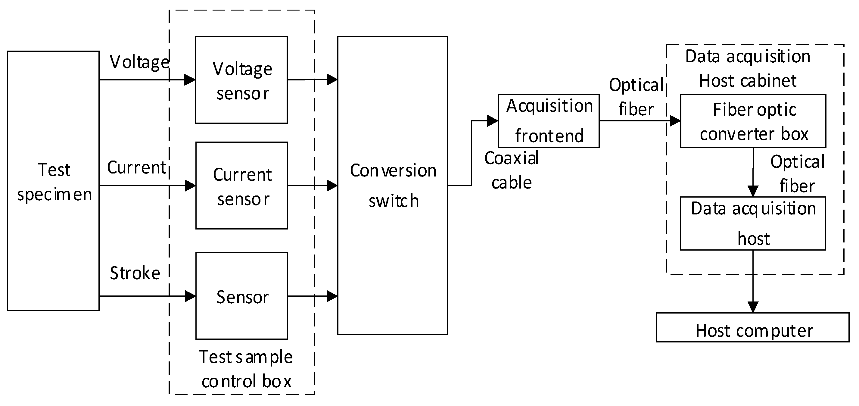
3.2. Test Data Acquisition System
3.3. Summary of the System's Advantages
- Pneumatic isolation switches are controlled by valve islands to achieve electrical isolation between the primary and secondary systems, eliminating switch failures caused by electromagnetic interference. The ring-shaped PROFINET network, combined with multimode optical fibers, enables efficient communication and strong anti-interference capabilities, ensuring stable data transmission.
- The sequential control technology precisely controls the test process, operates equipment in an orderly manner, and selects the closing phase angle, reducing human intervention and enhancing the repeatability and consistency of tests.
- It has high sampling rates, high precision, and multi-channel input capabilities, meeting the requirements for accurate measurement of multiple parameters in high-capacity tests.Equipment is arranged according to functions. Multimode optical fibers are used for data transmission to reduce electromagnetic interference, prevent high-voltage hazards, and ensure the stability of data acquisition and sequential control.
- Sensors are selected reasonably and connections are optimized. Anti-interference algorithms are integrated into the software to reduce electromagnetic interference, achieve voltage isolation, and ensure the safety of personnel.
- Testing: It accurately controls the action sequence of equipment, ensuring that the high-capacity test process is carried out in an orderly manner and guaranteeing the accuracy and reliability of tests. It optimizes test conditions, reduces the impact of differences in the closing phase angle on test results, and improves the accuracy and consistency of test results.
- It realizes automated operation, reduces human errors, and makes tests more standardized and normalized. It ensures that test conditions and procedures are consistent during operations at different times and by different personnel, providing reliable data for equipment performance evaluation.
4. High-Capacity Test Process Control
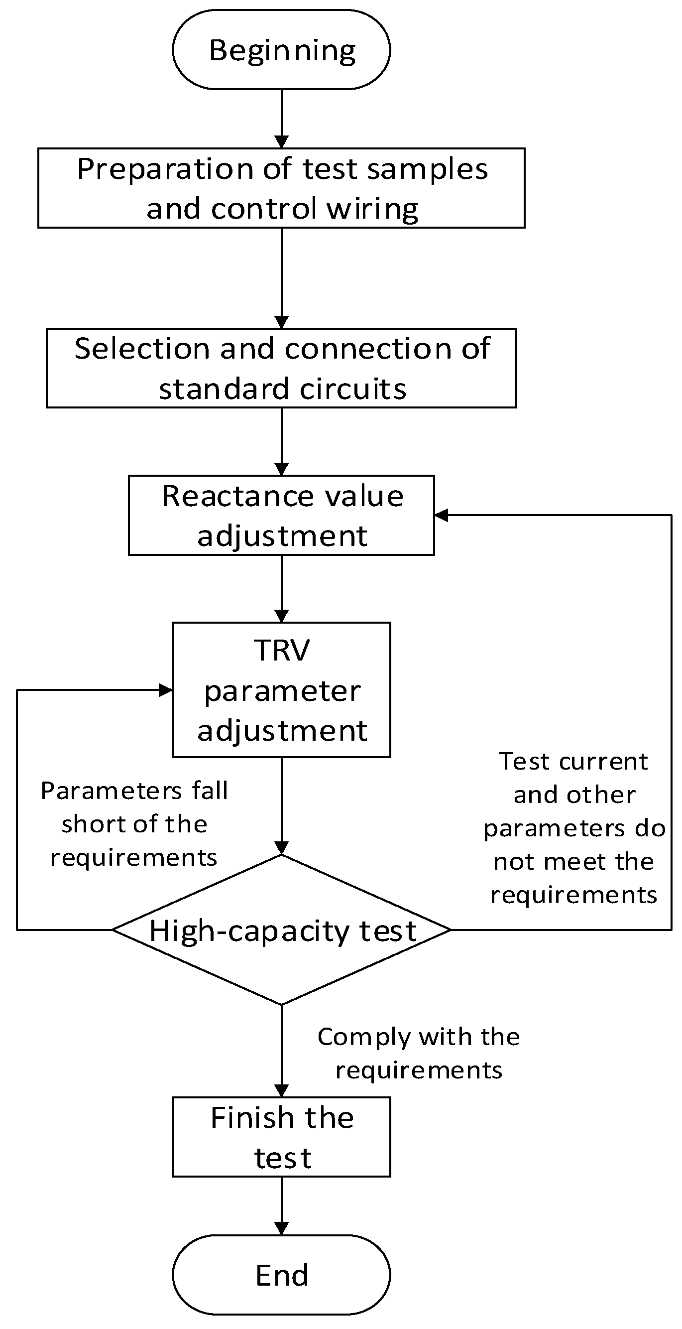
- Sample Preparation: based on the test plan, select the test sample and secure it in the test station. Connect the necessary data acquisition lines, sequential control lines, and other required connections.
- Parameter Input: input the test parameters into the control computer. The system automatically selects the standard circuit based on the parameters.
- Circuit Configuration: the program automatically closes the isolating switches to configure the circuit and selects the reactor value, adjusting the reactor's impedance accordingly.
- TRV Parameter adjustment: adjust the transient recovery voltage (TRV) parameters according to the test requirements and the expected TRV waveform.
- Parameter Fine-tuning: fine-tune the TRV and reactor parameters based on the preliminary test results.
- Test Completion: complete the test in accordance with the specified requirements.
5. Conclusions
- 1).
- Standardization of test circuits
- 2).
- Automation of test monitoring and control systems
Author Contributions
Funding
Data Availability Statement
Conflicts of Interest
References
- Jiang, B. Building a new power system for 30·60 goals: thoughts on china's power 4.0. Global energy interconnection 2021, 4, 534–541. [Google Scholar]
- Voropai, N.; Podkovalnikov, S.; Chudinova, L. The evolution of interstate power grid formation. Global energy interconnection 2021, 4, 335–353. [Google Scholar] [CrossRef]
- Sheng, G.H.; Qian, Y.; Luo, L.G.; et al. Key technologies and application prospects for operation and maintenance of power equipment in new power systems. High Voltage Engineering 2021, 47, 3072–3084. [Google Scholar]
- Chen, J.; Wang, Y.; Huang, H.; et al. Application research on live detection of partial discharge in 10kV switchgear based on multi-dimensional diagnosis technology. Distribution & Utilization 2016, 33, 64–68. [Google Scholar]
- Li, L. Application of intelligent monitoring and automation technology in power systems. Electronic technology 2024, 53, 328–329. [Google Scholar]
- Chen, Shuyong, Song, Shufang, Li, Lanxin; et al. Key technologies and prospects for the transformation of power systems towards carbon neutrality. proceedings of the CSEE (Proceedings of the Chinese Society for Electrical Engineering) 2021, 41, 3989–4003. [Google Scholar]
- Zhang, Q.; Wei, L.; Su, W.; et al. Commissioning of intelligent switchgear based on IEC61850 message simulation and analysis technology. High Voltage Apparatus 2014, 50, 91–95, 101. [Google Scholar]
- Li, G.; Yao, S.; Du, W.; et al. Research on the capacity test circuit of uhv circuit breakers. High Voltage Apparatus 2013, 49, 6–11. [Google Scholar]
- Zhang, Q.; Sun, H.; Tian, M.; et al. Current status and development trends of on-line insulation monitoring technology for high-voltage switchgear. High Voltage Apparatus 2023, 59, 1–11. [Google Scholar]
- Jiang, Z.; Yan, D.; Wang, P.; et al. Research on high-capacity test circuit for 550 kV/80 kA circuit breakers. High Voltage Apparatus 2023, 59, 200–206. [Google Scholar]
- Kang, Z. Design of control system for high-voltage high-capacity laboratory. Electrical Engineering & Electronics 2017, 11, 74–76. [Google Scholar]
- Dai, J.; Zhang, S.; Shen, J.; et al. Research on modeling method and one-click sequential control scheme for high-capacity test system. Global energy interconnection 2023, 6, 660–669. [Google Scholar]
- Chen, H.; Lin, J.; Luo, Y. Research on synchronous control system for synthetic testing. electric drive automation 2017, 39, 56–58. [Google Scholar]
- Synthetic testing of high-voltage alternating current circuit breakers: IEC 60427-2000. International electrotechnical commission, 2000.
- Wang, Y.; Zhang, J.; Pan, C.; et al. Review of research on multi-dimensional performance evaluation indexes for integrated smart energy. Global energy interconnection 2021, 4, 207–225. [Google Scholar]
- Chen, G.; Guo, W. Application of valve island technology in high-voltage high-capacity laboratory. automation instrumentation 2015, 36, 33–36. [Google Scholar]
- Li, G.; Gao, X.; Liu, H.; et al. High-capacity short-circuit breaking and making test technology for high-voltage ac circuit breakers. High voltage apparatus 2018, 54, 68–75. [Google Scholar]
- Gao, X.; Ji, X.; Ma, J.; et al. Analysis and discussion on short-circuit test procedures for high-capacity generator circuit breakers. High voltage apparatus 2017, 53, 172–177. [Google Scholar]
- Bai, Y.; Li, P.; Guan, Y.; Fang, C.; Guo, J.; Wang, Z.; Quan, H. Research on TRV breaking characteristics and suppression measures of high-capacity generator circuit breakers. High voltage apparatus 2024, 60, 92–100. [Google Scholar]
- Liu, Z.; Zhao, Q.; Huang, S.; et al. Brief overview of the control system in high power laboratories. High Voltage Apparatus 2018, 54, 237–241. [Google Scholar]
- Cao, L.; Zhu, X.; Wang, S. Research of computer aided analysis system in high power Lab. High Voltage Apparatus 2002, (02), 32–34. [Google Scholar]
- Chen, G.; Guo, W. Development of control system for impulse generator set based on s7-300. Electric automation 2015, 37, 87–89. [Google Scholar]
- Jiang, Z.; Yan, D.; Wang, P.; et al. Research on High power test circuit for 550 kV/80 kA circuit-breaker. High Voltage Apparatus 2023, 59, 200–206. [Google Scholar]
- Li, G.; Gao, X.; Liu, H.; et al. High-power short-circuit making and breaking test technology for high-voltage AC circuit breakers. High Voltage Apparatus 2018, 54, 68–75. [Google Scholar]
- Huang, S.; Gao, X.; Liu, H.; et al. Calculation of current zero di/dt and trv peak uc for asymmetric current interruption test t100a. High voltage apparatus 2015, 51, 163–167. [Google Scholar]
- Zhou, X.; Lin, Z.; Liu, C.; et al. Calculation of the envelope of transient recovery voltage waveform using the successive approximation method. High voltage apparatus 2018, 54, 159–163. [Google Scholar]

| No. | Technical parameter | Numerical value |
| 1 | Voltage ratio | 330/(2×60 + 2×12.5) kV |
| 2 | Rated capacity | 8,000 kVA |
| 3 | Impedance voltage (Uk) | 0.4% |
| 4 | Rated primary-side voltage | 330kV |
| 5 | Rated secondary-side voltage | 12kV;24kV;40.5kV |
| 6 | Maximum short-circuit capacity | 1828MVA |
| Uc | t3 | td | |
| Simulation results | 20.2kV | 23μs | 3μs |
| Test results | 20.6kV | 26μs | 4μs。 |
| Phase A current | Phase B current | Phase C current, | Proportion of DC component in phase A current | Proportion of DC component in phase B current | Proportion of DC component in Phase C current |
| 19.0kA | 18.9kA | 19.1kA | 3.1% | 8.3% | 5.2% |
| 19.0kA | 18.9kA | 19.1kA | 7.3% | 2.6% | 6.9%。 |
Disclaimer/Publisher’s Note: The statements, opinions and data contained in all publications are solely those of the individual author(s) and contributor(s) and not of MDPI and/or the editor(s). MDPI and/or the editor(s) disclaim responsibility for any injury to people or property resulting from any ideas, methods, instructions or products referred to in the content. |
© 2025 by the authors. Licensee MDPI, Basel, Switzerland. This article is an open access article distributed under the terms and conditions of the Creative Commons Attribution (CC BY) license (http://creativecommons.org/licenses/by/4.0/).


