
Submitted:
17 February 2025
Posted:
18 February 2025
You are already at the latest version
Abstract
The paper presents numerical study of the TLP-supported NREL 5MW wind turbine model under aligned and misaligned extreme wind-wave excitations. The analyses are conducted using OpenFAST dedicated software as well as specially developed simulation framework based on Comsol Multiphysics FEM model that was imported to MATLAB/Simulink environment using eigenvalue decomposition method. The Comsol/MATLAB/Simulink simulation model was equipped with 20 ton passive tuned vibration absorber (TVA) similarly to a standard OpenFAST’s solution, or with a controlled 10 ton TVA, utilising magnetorheological (MR) damper, operating simultaneously with the force actuator (forming hybrid H-MR-TVA), or independently – forming semiactive MR-TVA. The implementation of semiactive/hybrid 10 ton TVA tuned to tower 1st bending mode for the TLP-supported NREL 5MW wind turbine is a promising alternative to 20 ton passive TVA. Both, MR-TVA and H-MR-TVA, provide more favourable tower vibration mitigation results for aligned wind-wave conditions: the reduction of maximum tower deflection reaches 11.2% with respect to 20 ton passive TVA, and 14.9% with regard to structure without the TVA. The reduction of root-mean-square tower deflection is up to 4.2% / 2.9%, respectively, for along-the-waves critical direction. TVA stroke reduction reaches up to 18.6% (regarding 20 ton passive TVA). For misaligned excitations, controlled 10 ton TVA solutions excel in tower extreme deflection reduction as well as TVA stroke minimisation. The maximum tower deflections are reduced by up to 4.3% / 4.8% with regard to 20 ton passive TVA for 45° / 90° misalignments (respectively). This is accompanied with up to 22.2% / 34.4% stroke reduction (45° / 90° misalignment respectively). On the contrary, 20 ton passive TVA is slightly better in lowering the root-mean-square tower deflections: 0.1% / 2.3% for 45° / 90° misalignments. It is also worth emphasizing that maximum stroke of the selected H-MR-TVA variant does not exceed 2.427 m across all the regarded worst-case-scenario wind and wave excitations, which opens a field for more flexible 10 ton TVA location options, including tower sections that are favourable vibration mitigation solutions’ locations. The implementation of 10 ton passive TVA tuned to tower 1st bending mode is not recommended – the uncontrolled TVA of low mass ratio is ineffective for the regarded demanding excitation conditions. The results of the current research may be used for the design of the full-scale controlled TVA system serving the TLP-supported floating offshore NREL-5MW-class wind turbine structure.
Keywords:
floating offshore NREL 5MW wind turbine
; tension leg platform
; wind-wave misalignment
; structural vibration
; hybrid tuned vibration absorber
; magnetorheological damper
1. Introduction
Floating offshore wind turbines (FOWTs) have become a pivotal technology in the global transition to renewable energy, addressing the need to harness wind resources in deep-sea regions where traditional fixed-bottom installations are unfeasible due to economic and structural limitations [1,3]. Offshore locations provide significant advantages, including stronger and more consistent wind profiles compared to onshore or shallow-water environments, enabling higher energy yields over the turbine’s operational lifespan [2]. However, deploying wind turbines in these regions requires advanced support structures capable of withstanding harsh marine conditions, such as turbulent winds, high waves, and strong currents [3,5].
Among the floating support platforms, Tension Leg Platforms (TLPs) have gained particular recognition for their ability to provide exceptional stability in deep waters while minimizing environmental impact through a compact seabed footprint [4,6]. TLPs are designed with a buoyant hull tethered to the seabed using vertical mooring lines kept under constant tension. This tensioning minimizes vertical motions (heave) and rotational displacements (pitch and roll), critical for maintaining the operational reliability and efficiency of large-scale wind turbines, such as the widely referenced NREL 5MW model [5]. Stability provided by TLPs reduces fatigue loads on turbine components, increasing their lifespan and decreasing maintenance costs, which are often the largest operational expense in offshore wind systems [5,6]. Furthermore, TLPs are particularly suitable for deep-water environments exceeding 50 meters in depth, making them a versatile option for expanding wind energy production into areas previously considered inaccessible [4,6,11].
Despite these advantages, TLP-supported FOWTs face significant challenges associated with structural vibrations caused by environmental and operational forces [7,8]. Offshore environments are inherently dynamic, with wind turbulence, wave-induced motions, and ocean currents generating complex loads on turbine structures [4,9]. These external forces are further exacerbated by internal dynamics, including rotor imbalances, nacelle oscillations, and drivetrain vibrations, which interact with the platform-tower system, amplifying the structural response [7]. This interaction leads to coupled motions between the floating platform and the turbine tower, intensifying vibratory responses and increasing fatigue loads on critical components [8,9,13]. Without effective mitigation strategies, these vibrations can reduce energy production efficiency, compromise structural integrity, and result in costly repairs [6,9,14].
To address these issues, researchers have developed a variety of vibration control strategies, among which tuned vibration absorbers (TVAs) stand out as a promising solution [8,10]. TVAs are auxiliary systems that dissipate vibratory energy by introducing a secondary mass-spring-damper mechanism into the structure. Passive TVAs, which are tuned to specific frequencies, have been widely implemented in engineering applications due to their simplicity and cost-effectiveness [10]. However, their performance is limited in offshore environments where excitation frequencies vary significantly due to the stochastic nature of wind and wave loads [8].
Semi-active and hybrid TVAs have been developed to overcome these limitations by incorporating adaptive technologies such as magnetorheological (MR) dampers and active actuators, which allow for real-time adjustments to damping and stiffness properties [8,12,13,15]. Semi-active TVAs utilizing MR dampers represent a significant improvement over passive systems by providing dynamic adaptability to changing load conditions [8]. These systems have demonstrated the ability to reduce nacelle accelerations and tower base loads under irregular wave patterns and gusty wind scenarios, enhancing the stability of TLP-supported turbines [8,16]. Hybrid TVAs further extend these capabilities by integrating active actuators, enabling precise control over damping and stiffness while mitigating both low- and high-frequency vibrations simultaneously [8]. However, hybrid systems also introduce challenges related to increased complexity, energy consumption, and scalability, particularly for large-scale offshore wind applications [9,17].
Experimental validation has been critical to advancing vibration mitigation strategies for TLP-supported FOWTs [7,10,18]. Scaled model tests on TLP-supported NREL 5MW turbines have provided valuable insights into the dynamic behaviour of these systems under realistic environmental conditions [10,17,19]. These experiments have confirmed the effectiveness of advanced TVA configurations in reducing tower deflections, minimizing nacelle accelerations, and improving overall system stability [10]. Furthermore, integrating wave energy conversion devices like oscillating water columns (OWC) has added another layer of complexity that requires coupled control strategies to address both structural and hydrodynamic dynamics [7,20].
Theoretical advancements in TVA design and control algorithms have complemented experimental studies, enabling the optimization of vibration mitigation systems for offshore wind turbines [10]. Nonlinear control methods based on principles like the Pontryagin Maximum Principle have been employed to enhance hybrid TVA performance while minimizing energy consumption [9]. The use of quality indices that incorporate multiple performance metrics has facilitated the development of more robust vibration control systems [8]. These advancements pave the way for implementing adaptive vibration mitigation strategies capable of addressing unique challenges posed by TLP-supported FOWTs in offshore environments [7].
The continued development of vibration mitigation techniques is essential for enhancing the operational longevity and structural resilience of TLP-supported FOWTs. Recent studies have demonstrated that the implementation of nonlinear optimal-based reduced-stroke tuned vibration absorbers can significantly mitigate tower deflections, thereby improving fatigue resistance and extending the service life of turbine components [21]. Additionally, the effectiveness of passive tuned mass dampers in reducing dynamic loads due to wind-wave misalignment has been validated through both numerical and experimental investigations [22]. However, stroke limitations inherent to tuned mass dampers on floating structures introduce constraints that must be considered in design optimization processes [23]. Future research should focus on integrating adaptive control algorithms and multi-degree-of-freedom vibration suppression strategies to further enhance the robustness and adaptability of these mitigation systems under variable offshore conditions.
2. OpenFAST Model of the TLP-Supported NREL 5MW Wind Turbine
The dynamic behaviour of the TLP-supported NREL 5MW reference wind turbine was rigorously analysed using high-fidelity numerical simulations conducted in OpenFAST [24]. This advanced simulation tool incorporates aero-hydro-servo-elastic coupling, enabling a detailed examination of the complex interactions between aerodynamic, hydrodynamic, structural, and control system dynamics. The selected model, ‘5MW TLP’ represents a comprehensive framework for studying the intricate behaviour of floating offshore wind turbines (FOWTs) under realistic marine conditions (see Figure 1 and Table 1).
The simulation runtime of 1200 seconds provided a sufficiently long window for the system to exhibit its transient and steady-state dynamics. This duration ensured the extraction of meaningful data on time-domain responses, including tower deflections, and platform motions. The choice of runtime also supports fatigue analysis by offering insights into the cumulative loading experienced by the turbine components. A fixed time step of 12.5 ms was chosen for the simulations. This time step strikes a balance between computational cost and temporal resolution, ensuring that fast dynamic events, such as blade vibrations and control adjustments, are captured with high fidelity. The chosen value is consistent with OpenFAST's recommendations for analysing coupled aero-hydro-servo-elastic systems, minimising numerical errors while maintaining simulation efficiency.
Wind and wave forces were coupled in the simulations to reflect realistic offshore conditions. The interaction of these forces allowed for a detailed investigation of coupled excitations, particularly under scenarios where wind and wave directions were aligned. This alignment amplified structural responses, enabling the identification of critical load cases those with the highest potential to induce fatigue or structural instability. The varying wind directions were essential for comparative evaluations of the system's dynamic behaviour, providing a robust basis for assessing its reliability and operational limits. In addition to examining the system's response under operational loads, the analysis provided insights into the stability of the floating platform, particularly in the surge (along the waves) and sway (transversal) directions. These motions are closely tied to the integrity of the mooring system, which must balance platform stability against dynamic environmental forces. Similarly, tower responses, such as fore-aft and side-to-side displacements, were critical parameters for assessing the turbine's ability to withstand coupled wind and wave loads while maintaining its structural integrity over its operational lifetime.
To simulate realistic offshore conditions, the wind fields were generated based on a Weibull distribution with a scale parameter of 10 and a shape parameter of 2.0. This distribution resulted in a mean wind speed of 8.86 m/s and a standard deviation of 4.63 m/s at a hub height of 90 m above mean sea level. These wind profiles were designed to replicate typical offshore wind conditions, ensuring the relevance of the results to real-world scenarios. The aerodynamic thrust applied to the nacelle, denoted as Fe(t), was computed using rotor thrust characteristics derived from steady-state performance curves as a function of wind speed. The thrust asymmetry, resulting from the interaction of rotor blades with the tower, introduced continuous excitation of both fore-aft and side-to-side bending modes of the tower. This phenomenon is particularly critical at specific rotor azimuthal positions (e.g., 0°, 60°, 120°, etc.), where the aerodynamic loading peaks. Each realisation has a temporal resolution of 12.5 ms, ensuring high-fidelity representation of the coupled wind-wave excitation forces. The simulations focused on the most severe scenarios, where wind and wave forces were aligned (α=0ᵒ, see Figure 2), or misaligned (α=45ᵒ or α=90ᵒ), amplifying the vibratory response of the system.
The hydrodynamic forces acting on the TLP-supported wind turbine were modelled using the HydroDyn module in OpenFAST. This module is essential for accurately representing the interactions between the floating platform and the marine environment, particularly under irregular wave loading. The wave environment was simulated using the Bretschneider ocean wave spectrum, characterized by a significant wave height (Hs) of 2.5 m and a peak period (Tp) of 8.1 s. This spectrum was chosen to reflect realistic offshore conditions, ensuring accurate representation of wave-induced forces acting on the floating platform.
The interplay between aerodynamic and hydrodynamic forces produced significant structural vibrations in the turbine system. These vibrations were characterized by coupled motions of the floating platform and the tower, driven by the stochastic nature of the wind and wave fields. The fore-aft and side-to-side bending modes were found to dominate the tower dynamics, with the platform's surge and sway motions contributing to the overall system response. The data generated through these simulations provided a robust foundation for the subsequent analysis of vibration mitigation strategies, particularly the evaluation of tuned vibration absorbers (TVAs) and their effectiveness under realistic offshore conditions. By incorporating diverse environmental scenarios and leveraging the comprehensive modelling capabilities of OpenFAST, the study aims to address critical challenges associated with the operational stability and structural reliability of TLP-supported FOWTs in demanding marine environments.
The structural design of the turbine tower and the TLP floating platform was modelled with a high level of detail to capture the dynamic responses accurately. The tower's geometry was defined using 11 sections, representing the tower profile along its height. This segmentation allowed for precise modelling of variations in structural and material properties, ensuring that the simulation could accurately predict both localized and global dynamic behaviours under varying environmental loads. To account for energy dissipation within the tower, modal damping ratios were specified for the dominant vibration modes. These were set to 1% for the first and second fore-aft modes (along the waves propagation, x-direction) andalso for the first and second side-to-side modes (perpendicular to the waves propagation, y-direction) [25,26]. These modes capture the tower's response to wind and rotation-induced loadings, as well asplatform motions due to hydrodynamic loadings. The damping ratios reflect the inherent structural damping characteristics of the NREL 5MW reference wind turbine, ensuring that the dynamic responses observed in the simulation are realistic. Modal damping is critical in controlling vibrations and mitigating excessive displacements that could compromise the structural integrity or operational reliability of the turbine. The segmentation of the tower into 11 sections provided the basis for an accurate description of its geometry, including variations in diameter, thickness, and material properties along its height. This level of detail is essential for capturing the tower's flexibility and vibrational characteristics, which are influenced by both aerodynamic and hydrodynamic forces. The tower's shape and stiffness directly affect the distribution of stresses and the ability of the structure to withstand cyclic loading, particularly under coupled wind-wave excitation. By combining detailed geometric modelling with realistic damping parameters, the OpenFAST simulation framework effectively represents the tower's role as a key structural component of the turbine. It facilitates the analysis of interactions between the tower and other subsystems, including the floating platform and control mechanisms, under diverse environmental conditions. This detailed representation of the tower and platform provides a robust foundation for evaluating the turbine's operational stability and identifying potential areas for design optimization (particularly in terms of fatigue resistance and dynamic performance), as well as vibration control simulation platform synthesis, as for the current study (Figure 1).
Simulations were specifically designed to capture the effects of varying wind directions on the structural responses of the turbine tower and floating platform. Wind directions were considered at 0°, 45°, and 90° relative to the wave propagation direction, allowing for an evaluation of the system's behaviour under diverse load scenarios (Figure 2). To maintain aerodynamic efficiency and minimize misalignment losses, the nacelle yaw angle was adjusted during each simulation to align with the incoming wind. This setup mirrors operational strategies employed in real-world offshore wind farms, where yaw alignment plays a critical role in optimizing energy capture and reducing structural stresses.
The mooring system of the TLP-supported turbine was simulated using the MoorDyn module, which models the dynamic behaviour of mooring lines under environmental loads. This system plays a critical role in maintaining the stability of the floating platform, particularly in harsh offshore conditions where wind and wave forces can induce significant motions. The parameters of the mooring lines, presented in Table 2, are typical for offshore mooring lines used in floating wind turbine applications. The chosen diameter and mass provide sufficient weight and strength to withstand the tension induced by platform motions and environmental forces. The axial stiffness modulus ensures the lines can endure high tensile loads without excessive elongation, preserving the system's structural integrity and limiting platform displacements. The mooring system's geometry was defined using nodes positioned in three-dimensional space relative to the sea floor and platform. Each node's coordinates were specified to reflect the actual layout of the mooring lines: fixed points were anchored to the seabed, providing a secure base for the mooring lines, while platform attachment points were connected to the floating structure at strategic locations to distribute tension evenly across the platform. This spatial configuration ensures that the mooring system effectively counteracts environmental forces, balancing platform motions in surge (along the waves), sway (transversal), and heave (vertical) directions. The layout also minimizes the risk of excessive stress concentrations in the lines or attachments, contributing to the overall durability of the system. The interaction between the mooring lines and platform was dynamically simulated to capture the system's response to coupled wind-wave excitation. MoorDyn calculates the tension, elongation, and motion of each line in real-time, allowing for an accurate assessment of the platform's stability and the forces transmitted to the mooring anchors. By incorporating detailed line properties and spatial configurations, the simulation framework provides a robust analysis of the mooring system's performance. This approach ensures that the platform remains stable even under extreme environmental conditions, supporting the operational reliability of the TLP-supported wind turbine.

Table 1.
NREL 5MW baseline wind turbine parameters.
| Rotor Diameter | 126 m |
| Hub Height | 90m |
| Wind Speed: Cut-In, Rated, Cut-Out |
3.0, 11.4, 25.0 m/s |
| Rotor Speed: Cut-In, Rated | 6.9, 12.1 rpm |
| Rotor Mass | 110.2 t 240.0 t 347.5 t |
| Nacelle Dimension | 18 x 6 x 6 m |
Table 2.
TLP and mooring system parameters.
| Platform mass | 8600.41 t |
| Displacement | 12179.6 m3 |
| Vertical centre of gravity of the platform (below sea level) | –40.612 m |
| Draft, freeboard | 47.89, 10-12 m |
| Water depth | 200 m |
| Number of tendons | 8 |
| Nominal tendon pretension (each) | 3931 kN |
| Tendon diameter | 0.127 m |
| Tendon mass per unit length | 116.0 kg/m |
| Tendon axial stiffness modulus | 1.5×10⁹ N |
The hydrodynamic forces acting on the TLP-supported wind turbine were modelled using the HydroDyn module in OpenFAST. This module is essential for accurately representing the interactions between the floating platform and the marine environment, particularly under irregular wave loading. The wave environment was simulated using model no. 3, which corresponds to a white noise spectrum representation of irregular waves. This model captures the stochastic nature of wave forces, representing them as a broadband spectrum of energy distributed across different frequencies. Such an approach ensures that the simulations realistically mimic offshore conditions, where waves are rarely periodic but instead vary in amplitude and frequency over time. The selection of the white noise spectrum allows for high-fidelity representation of irregular wave excitation, providing critical insights into the platform's response under dynamic loading conditions. This wave model is particularly useful for analysing fatigue and stability in floating offshore wind turbines, as it introduces a wide range of frequencies that excite various structural modes. The water density was set to the default value specified in OpenFAST. This parameter, typically assumed to be 1025 kg/m³, represents the density of seawater in standard offshore conditions. The default value ensures consistency with other modules in OpenFAST and is representative of the physical properties of the marine environment where the turbine operates. The hydrodynamic forces generated by the irregular wave field interact with the floating platform, inducing motions in six degrees of freedom: surge, sway, heave, roll, pitch, and yaw. The HydroDyn module computes these forces based on the platform's geometry, water properties, and wave characteristics, ensuring accurate modelling of the coupled dynamic behaviour. The use of irregular wave modelling in combination with detailed platform dynamics enables the simulation to capture complex behaviours such as resonance effects, damping contributions from the mooring system, and the interaction of aerodynamic and hydrodynamic forces. This comprehensive approach provides critical insights into the system's stability and operational reliability under real-world offshore conditions. By leveraging HydroDyn's capabilities, the simulation framework ensures that the turbine's design and performance are rigorously tested against the challenges posed by dynamic marine environments. This enables robust assessments of the platform's stability, fatigue life, and suitability for deployment in offshore wind farms.
The aerodynamic forces acting on the turbine rotor and tower were modelled using the AeroDyn module, which provides a comprehensive framework for analysing the aerodynamic behaviour of wind turbines. The module accounts for both rotor dynamics and the interaction between the airflow and the tower structure, enabling detailed simulations of the turbine's performance under realistic wind conditions. The aerodynamic forces on the rotor blades were computed using the blade element momentum theory (BEMT), selected as the wake model. BEMT combines the principles of momentum conservation with blade element theory, allowing for precise calculations of lift and drag forces at different sections of the blade. This model accounts for variations in wind speed, blade pitch angles, and rotor geometry, providing an accurate representation of the aerodynamic loading on the turbine. By dividing the rotor blades into discrete elements, BEMT calculates the forces and moments acting on each section, enabling a detailed analysis of the rotor's performance under varying wind conditions. The choice of BEMT as the wake model ensures that the simulations capture both steady-state and transient aerodynamic effects, including those caused by changes in wind speed and direction. This level of detail is essential for evaluating the turbine's efficiency, stability, and structural loads. The influence of the tower on the airflow was explicitly included in the simulations. The AeroDyn module incorporates potential flow theory to model the aerodynamic interaction between the wind and the tower structure. This feature calculates the aerodynamic forces acting on the tower, accounting for the deflection and disturbance of the wind field caused by the tower's presence. Including the tower's aerodynamic influence is crucial for capturing the transient loading effects on the rotor blades as they pass through the wake of the tower. These effects, commonly referred to as tower shadow effects, lead to periodic variations in aerodynamic loading on the blades. Accurately modelling these interactions is vital for assessing the dynamic response of the turbine and identifying potential sources of fatigue in the blade and tower structures. By combining the BEMT rotor model with the tower influence model, the AeroDyn module provides a comprehensive simulation of the aerodynamic forces acting on the turbine. This integration enables the analysis of coupled aerodynamic and structural dynamics, which are critical for understanding the turbine's behaviour under realistic wind conditions. The detailed representation of aerodynamic parameters in AeroDyn ensures that the turbine's design and operational strategies are thoroughly evaluated, providing insights into performance optimization and structural reliability.
The control system of the wind turbine was modelled using the ServoDyn module in OpenFAST. This module provides a robust framework for simulating the operational control mechanisms of the turbine, including pitch control, generator torque control, and yaw alignment. In this study, special attention was given to the blade pitch control system, as it plays a critical role in regulating aerodynamic loads and maintaining turbine efficiency under varying wind conditions. The blade pitch control system was configured in mode 5, which corresponds to the use of a Bladed style DLL for advanced control functionality. This setup allows the turbine to utilize a dynamic pitch control algorithm, typically implemented in external software, to adjust the pitch angles of the rotor blades in response to changes in wind speed and load conditions. By employing the Bladed style DLL, the control system benefits from enhanced flexibility and precision, enabling real-time optimization of blade angles to maximise energy capture during low wind speeds and reduce excessive aerodynamic loads during high wind speeds. This advanced control mechanism ensures the turbine operates efficiently across its entire operational range. The blade pitch control system was activated at 0 seconds, meaning that the control logic was engaged from the start of the simulation. Immediate activation ensures that the blades are dynamically adjusted as soon as the simulation begins, allowing the system to respond to transient conditions, such as gusts or shifts in wind direction, right from the outset. The integration of the ServoDyn module with the aerodynamic (AeroDyn) and structural (ElastoDyn) modules ensures that the control system interacts seamlessly with the turbine's dynamics. The real-time adjustments to blade pitch angles influence the aerodynamic forces acting on the rotor, which in turn affect the structural loads on the tower and platform. This coupling is critical for accurately simulating the turbine's behaviour under realistic offshore wind conditions. The detailed modelling of the blade pitch control system in ServoDyn not only supports the evaluation of turbine performance but also provides insights into the effectiveness of advanced control strategies in reducing fatigue loads and extending the turbine's operational life.
Global simulation settings ensure that the time-domain responses of the turbine are accurately captured and that the results are reliable for subsequent analysis. The error level set to fatal ensures that any critical errors encountered during the simulation would immediately terminate the process; thus, the simulation results remain reliable and free from the propagation of errors that could compromise the validity of the analysis. The combination of a long simulation duration, high temporal resolution, and strict error handling guarantees the integrity of the outputs, and supports a robust evaluation of the turbine's structural and operational performance, providing critical insights for design optimization and reliability assessment.
The obtained simulation outputs provided a comprehensive dataset for analysing the structural and dynamic responses of the turbine. The primary focus was on the displacement and motion of the tower and platform, as these aspects are critical for assessing the turbine's structural integrity and operational reliability under coupled wind and wave loading. Several variables were selected as key indicators for analysis, providing insights into the aerodynamic, structural, and dynamic behaviour of the turbine system. The components of wind velocity at the rotor plane are represented by variables: Wind1VelX and Wind1VelY, used further in this study. Accurate measurement of these components is essential for evaluating the aerodynamic loading on the rotor blades. Variations in these values, influenced by turbulence and wind shear, directly impact rotor performance and structural loads on the tower. Analysing these components helps assess the effectiveness of the control system in managing aerodynamic loads and maintaining operational stability. The rotor angular velocity variable (RotSpeed variable) serves as a key performance indicator, reflecting the turbine’s ability to convert wind kinetic energy into mechanical energy. A stable rotor speed indicates efficient energy production and operational stability. Fluctuations in rotor speed are closely monitored to detect potential instabilities or anomalies in the control system. The fore-aft (along the waves propagation direction x) and side-to-side (transversal direction y) relative displacements of the tower tip, represented by TTDspFA and TTDspSS variables, respectively, are the system outputs used in the next section for analyses. These variables are critical for understanding the structural dynamics of the tower under coupled wind and wave excitation. Fore-aft displacement reflects the bending of the tower, influenced by x-direction aerodynamic forces and platform motions in surge. The resultant shear force at the nacelle yaw bearing is represented by YawBrFxp variable. Side-to-side displacement captures tower bending driven by y-direction aerodynamic loads and sway motions of the platform (the resultant nacelle yaw bearing shear force is YawBrFyp). In current study, main emphasis was placed on these tower relative displacements (bending deflections), as they are directly related to the long-term fatigue life of the tower – repeated cyclic loading in these modes can lead to material degradation and eventual structural failure. Tower tip displacements are the most critical for the operational stability of the nacelle and the integrity of the rotor system. Excessive displacements in these directions can compromise the turbine's performance and structural reliability, making them crucial metrics for design validation and optimization. By analysing these key variables, the study provides a robust understanding of the turbine's dynamic behaviour under realistic offshore conditions, and form a reliable basis for vibration controlsystem platform analysis, design, and synthesis. The insights gained are instrumental in optimizing the design, enhancing structural reliability, and ensuring the long-term operational efficiency of TLP-supported offshore wind turbines. The horizontal motions of the floating platform analysed here are described by PtfmSurge and PtfmSway variables, used in the next sections. Surge refers to the motion of the platform along the wave propagation direction, driven by longitudinal forces from the waves (HydroFxi variable) and x-component of aerodynamic forces. Sway represents motion perpendicular to the wave direction, influenced by y-component of aerodynamic forces and transversal wave loads (HydroFyi variable). These motions are essential for evaluating the platform's stability and the effectiveness of the mooring system. Excessive surge and sway motions can lead to misalignments of the rotor with the wind direction, reducing energy capture efficiency and increasing structural loads.
3. OpenFAST Analyses Results
The results of the numerical simulations conducted in OpenFAST are presented in this section. These simulations capture the dynamic responses of the TLP-supported NREL 5MW wind turbine under varying wind angles (0°, 45°, and 90°) relative to the wave direction. The analysis focuses on key structural and aerodynamic parameters that influence the turbine's stability, operational efficiency, and fatigue life.
Figure 3 illustrates the variations in wind velocity and rotor thrust over time, highlighting the impact of wind direction on aerodynamic loading. Figure 4 delves into the motions of the floating platform, specifically TLP surge and sway displacements, which are critical for understanding platform stability under different wind angles. Figure 5 explores the fore-aft (along the waves) and side-to-side (transversal) displacements of the tower tip, emphasizing the coupled effects of wind and wave excitations on tower dynamics.
Observing Figure 3 it can be seen that rotor thrust has smaller fluctuations for larger wind-wave alignment angles, especially α=90°, for which platform movement parallel to the wind has much smaller amplitude. Considering the platform movements, shown in Figure 4, a translational shift in surge may be observed for lower wind angles (especially α=0°), as well as greatest value of peak-peak surge. On the contrary, a shift in sway may be observed for higher angles (especially α=90°) that is associated with greatest value of peak-peak sway. Apart from this, surge and sway time histories exhibit some level of similarity for different alignment angles. The translational responses of the platform are dominated by the fundamental surge and sway natural frequencies, which, for the examined FOWT, are shown as peaks in the power spectral density (PSD) characteristics of Figure 6(a)(b) at 0.0171 Hz (surge) and 0.0146 Hz (sway), corresponding to periods of 58.5 and 68.5 seconds, respectively. These natural frequencies are strongly influenced by the mooring length (i.e. water depth), mooring tension and platform inertial characteristics. At higher frequencies the surge response (RAO) drops down, up to frequencies typically around 0.16 Hz, but there is also a peak (see Figure 6(a)), which corresponds to the coupling with the pitch motion of the platform. Indicative RAOs of surge motion wave been experimentally verified in [17]. When analysing Figure 5 it is clear that the along the waves (x-direction) tower deflections are critical (compared with transversal deflections) and become greater for larger alignment angles (especially for α=90° wind direction), while the transversal tower deflections become smaller. This is a result of relatively large aerodynamic damping for NREL 5MW wind turbine that may reach 7% for along-the-wind (rotor axle) direction, and is more than ten times smaller for perpendicular vibrations [27].
The presented results provide a comprehensive overview of the NREL 5MW wind turbine and TLP platform dynamic behaviour, offering insights into the interplay between aerodynamic and hydrodynamic forces, as well as their impact on structural responses. The presented data forms the basis for evaluating the effectiveness of the floating wind turbine design, and identifying critical areas for further optimisation, including synthesis of real-time controlled, TVA-based structural vibration reduction system.
4. Tuned Vibration Absorber (TVA) for NREL 5MW Wind Turbine
The implementation of the TVA for the NREL 5MW wind turbine is a strategic enhancement aimed at addressing the complex vibration phenomena characteristic of TLP-supported turbines operating in offshore environments. The TVA system is designed to counteract dynamic loads caused by coupled aerodynamic and hydrodynamic forces, significantly reducing structural fatigue and enhancing operational stability. The TVA features a dual-axis configuration, which allows simultaneous control over the critical fore-aft (along the waves) and side-to-side (transversal) modes of vibration (see Figure 2). This dual-axis capability is essential given the anisotropic nature of the forces acting on the turbine, where wind thrust predominantly affects the fore-aft direction while wave-induced motions and lateral wind loads impact the side-to-side dynamics.
This solution integrates seamlessly with the nacelle structure, positioned at a height of 90 m above the reference point to maximize its influence on the primary bending modes of the tower. The strategic placement of the TVA not only ensures effective mitigation of vibrations but also aligns with the turbine’s design philosophy of optimizing mass distribution and minimizing torsional effects. The TVA’s components are carefully tuned to match the natural frequencies of the tower's dominant modes, with specific parameters listed in the table. Additionally, the operational range ensures sufficient flexibility to accommodate extreme load scenarios without compromising the damper's structural integrity. Through its passive operation mode, the TVA reliably reduces tower deflections and nacelle accelerations, critical metrics for ensuring the long-term reliability of the wind turbine. In extreme cases, auxiliary stop-spring mechanisms are activated to provide additional resistance and protect the system from overloading. This layered approach to vibration mitigation underscores the robustness of the TVA as a key component in the overall stability strategy of the NREL 5MW wind turbine system (see Table 3).
The TVA utilised in this study is a dual-axis system with independent degrees of freedom (DOFs) in the fore-aft and side-to-side directions. This design is specifically engineered to address the complex vibration challenges posed by the coupled aerodynamic and hydrodynamic excitations characteristic of offshore environments. By operating independently in both axes, the TVA effectively mitigates the vibratory forces, ensuring stability and extending the structural lifespan of the wind turbine. The symmetrical distribution of the TVA’s mass is a critical feature that minimizes asymmetrical load effects on the turbine structure. This balance reduces the risk of secondary torsional vibrations and ensures consistent performance under varying load conditions. The key parameters of the OpenFAST’s TVA implementation, including its mass, spring stiffness, damping coefficient, and displacement range, are calibrated to match the dynamic requirements of the NREL 5MW wind turbine (Table 1). This tuning ensures the TVA counteracts the dominant structural vibration modes of the tower, enhancing its efficiency in energy absorption and damping. This characteristic is particularly valuable in the stochastic offshore environment, where wind and wave loads vary significantly over time. This dual-axis TVA design offers the flexibility required to handle transient and extreme environmental loads, maintaining its effectiveness even under severe conditions and protecting the turbine structure from excessive stresses. Its ability to operate independently in two critical directions makes it a cornerstone of the turbine’s vibration management strategy.
The TVA is strategically installed at a height of 90 m above the reference point, aligning with the approximate location of the nacelle in the NREL 5MW wind turbine. This strategic placement is based on a careful analysis of the tower's dynamic behaviour and the need to target its critical bending modes. By positioning the TVA at this elevation, it exerts maximum influence on the first bending modes, which are most susceptible to coupled aerodynamic and hydrodynamic excitations. The centralized placement within the nacelle structure ensures balanced load distribution and minimizes the risk of torsional vibrations, maintaining structural integrity and operational stability.
The placement at 90 m allows the TVA to directly address critical vibration modes, particularly those amplified by wind thrust and platform motions, enhancing the tower's ability to withstand dynamic loads and reducing fatigue stress. Additionally, the nacelle's location provides convenient access to the TVA, facilitating inspections, adjustments, or component replacements, which reduces downtime and maintenance costs. Centralized positioning ensures the TVA's operation does not introduce additional rotational forces that could interfere with the turbine’s overall stability. This precise integration results in a smoother and more predictable dynamic response. The placement of the TVA at this height is supported by detailed simulations and structural analyses, confirming its effectiveness in mitigating vibrations and enhancing the longevity of the turbine's key components. This integration represents a robust solution to the unique challenges posed by offshore wind turbine dynamics.
The TVA operates as a passive system within predefined displacement limits, effectively counteracting vibrations through its integrated spring-damper mechanism. This passive approach ensures that the TVA responds to structural oscillations with minimal external intervention, providing a reliable and efficient means of vibration mitigation. To enhance the passive TVA robustness under extreme load scenarios, it is equipped with stop-bumper mechanisms. These secondary components activate as the system approaches its displacement limits, providing additional stiffness and damping. This design feature protects the TVA and the turbine/nacelle structure from potential damage during extreme events, such as high wind gusts or severe wave impacts. The parameters of the stop-bumper mechanism, including stiffness and damping coefficient (see Table 3), ensure robust resistance to excessive deflections and efficient energy dissipation during high-displacement events. The combination of the primary spring-damper system and the auxiliary stop-bumpers creates a layered approach to vibration mitigation. This configuration enhances the TVA's ability to handle routine operational loads while also providing a fail-safe mechanism to maintain structural integrity under extreme conditions. By effectively managing both standard and exceptional dynamic loads, this passive TVA ensures the long-term stability and reliability of the NREL 5MW wind turbine. However, as it was recently proven [21], controlled TVA solutions may operate with reduced stroke length without compromising structure’s vibration attenuation properties by additional springs/dampers that lead to the TVA mistuning.
Apart from the 20 ton passive TVA regarded above, the previously studied 10 ton passive TVA, semi-active magnetorheological TVA (MR-TVA), and hybrid MR-TVA (H-MR-TVA) [13,21] is considered in the current work for comparison using a TLP-supported wind turbine Comsol/MATLAB/Simulink model, described in the next section.
5. Comsol/MATLAB/Simulink Model of the TLP-Supported NREL 5MW Wind Turbine with TVA
The implementation of a controlled, semi-active TVA using MRdamper (MR-TVA), as well as hybrid MR-TVA (H-MR-TVA) for the TLP-supported NREL 5MW wind turbine was based on the simulation model that was built using Comsol Multiphysics and MATLAB/Simulink environments. The reduced order model technique offered by Comsol Multiphysics is not operational for systems with any nonlinearity, while Comsol-Simulink full-order model co-simulation tool is not practically applicable for the regarded task due to its complexity and excitations’ rapidity (high derivatives of external inputs); in result, Comsol-Simulink co-simulation was extremely time-consuming and yielding error messages at time instants corresponding to sharp input changes at numerous points along the time axis. Thus, the proposed modelling method is developed as the original concept to address these issues.
The 3D beam element from the Structural Mechanics module under Comsol Multiphysics V6.3 environment was used to model the tower-TLP structure. All of the tower’s cross-section parameters [25,26] were averaged along its longitudinal dimension (z in Figure 7), while nacelle as lumped mass was assigned at its centre of gravity at 90 m height, this method resulting in accurate values of two initial tower bending modes’ frequencies along x and y direction (along the waves and transversal, respectively, see Figure 2): 3.2813 rd/s (0.5222 Hz) and 18.775 rd/s (2.9881 Hz; see Figure 7). The TLP cross-section and ballast parameters, along with tendons wire model (from Structural Mechanics library) with cumulativecross-section, mass, stiffness, and pretension were set according to [26]. An isotropic loss factor =2% was assigned to all structural materials, corresponding to the resultant modal damping ratio ≅1% (as ). The eigenvalue analysis of the structure was executed. Two initial bending modes for each of x and y directions were exported using probe table of eight point probes, incorporating x and y displacements and velocities at the tower tip (87.6 m above the tower base / OpenFAST’s reference point R, see Figure 8), and at the TVA location (90.0 m above the tower base). Using eigenvalue and eigenfrequency decomposition, 8th order state matrix was built for state-space MATLAB/Simulink model, while input matrix was tuned using OpenFAST 1200 seconds time series data, enabling horizontal x (i.e. along the waves) and y (transversal) direction forces at the tower tip (i.e. nacelle yaw bearing x and y forces), and forces from the MATLAB/Simulink hydrodynamics 4th order model. Tower tip fore-aft (x-) and side-to-side (y-)displacements and velocities were included in the state-space output matrix, while the hydrodynamics model yielded platform surge and sway outputs. The hydrodynamics model was tuned to the TLP surge fundamental frequency, based on OpenFAST output data and power spectral density (PSD) decomposition (see Figure 6). This model was fed with data from OpenFAST: x and y direction hydrodynamic forces Fhx, Fhy (HydroFxi, HydroFyi) acting on the TLP at the OpenFAST’s reference point R located at the mean sea level height (see Figure 8 for x-direction model), as well as x and y direction shear forces Fsx, Fsy (YawBrFxp, YawBrFyp) at the tower tip (nacelle yaw bearing), and included aerodynamic damping corrections (in both x and y directions) that are based on rotor speed (RotSpeed) and wind velocity (Wind1VelX or/and Wind1VelY) data from OpenFAST. For misaligned excitations of 45° / 90°, tower tip y-displacement bias correction of 0.10 m / 0.12 m (respectively) was necessary to match OpenFAST data. The TLP surge and sway displacements were designated by x0 and y0 (respectively), tower tip absolute displacements along the waves and transversal – by x1 and y1 (respectively), while TVA absolute displacements – by x2 and y2 (respectively; see Figure 8 for x-axis diagram). Thus, tower deflections, corresponding to OpenFAST’s variables, are equal to x1–x0 (along the waves, TTDspFA in OpenFAST), and y1–y0 (transversal, TTDspSS). Similarly, the TVA relative displacements are equal to x2–x1 (along the waves), and y2–y1 (transversal). Using so developed model, the quality indexes were determined, enabling its verification vs. OpenFAST numerical reference framework. The obtained results (see Table 4) exhibit high fidelity with respect to the OpenFAST-based results.
So built Comsol/MATLAB/Simulink model of the TLP-NREL 5MW FOWT was used for the TVA model implementation in the nacelle. As mentioned before, apart from OpenFAST’s passive 20 ton TVA, a 10 ton passive TVA, and previously developed MR-TVA/H-MR-TVA [13,21] is considered for analyses in the current research. The selection of 10 ton absorber mass is consistent with conditions described in [21,28]. A 10 ton TVA/MR-TVA/H-MR-TVA tuning frequency is selected to be equal to the 1st bending frequency of the model, i.e. 0.5222 Hz. The MR damper operated simultaneously with the force actuator in the TVA system, forming the hybrid H-MR-TVA (see Figure 8), or independently, forming the semiactive MR-TVA. The nominal MRdamper force was considered Fmrnom = 100 kN, while nominal force of active actuator was assumed Fanom1 = 7.1 kN (H-MR-TVAv1 version) or Fanom2 = 14.2 kN (H-MR-TVAv2 version). The resultant TVA parameters are presented in Table 5.
The dynamics of the MR damper and the force actuator (assumed to be of an electromagnetic type), including their operating characteristics nonlinearities, inertia (time constants) and time delays, were assumed in the Comsol/MATLAB/Simulink simulation model, the former also being embedded in the Hamilton-principle-based nonlinear control formulation and solution. This original recent development was proven to yield the most favourable results across all of the regarded passive, semi-active and hybrid TVAs, additionally assuring the lowest attained TVA stroke length [21].
6. Comsol/MATLAB/Simulink Analyses Results
Figure 9, Figure 10, Figure 11, Figure 12 and Figure 13 present the results obtained using Comsol/MATLAB/Simulink model: Figure 9 shows TLP surge and TLP sway time patterns, while Figure 10, Figure 11, Figure 12 and Figure 13 present tower tip displacements vs. time. Figure 9 and Figure 10 obtained for the system without the TVA exhibit close correlation with the respective OpenFAST data (see Figure 4 and Figure 5). The synthetic results are grouped in Table 6, Table 7, and Table 8 for 0°, 45°, and 90° wind-wave alignment, respectively.
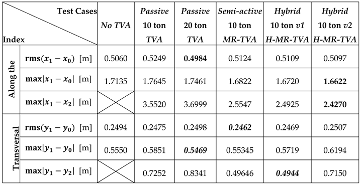
The obtained results prove the effectiveness and robustness of 10 ton controlled TVAs (MR-TVA and H-MR-TVA) in TLP-supported NREL 5MW tower deflection attenuation. For aligned wind and wave excitations (Table 6), H-MR-TVAv2 is the most favourable solution regarding the critical x-direction vibration, although both H-MR-TVAv1 and MR-TVA provide more beneficial properties than 20 ton passive TVA (with parameters based on OpenFAST solution) in terms of all: maximum tower deflection , root-mean-square tower deflection , and TVA maximum stroke . The maximum tower x-deflection reduction for H-MR-TVAv2 reaches 11.2% vs. 20 ton passive TVA, and 14.9% vs. structure without the TVA. The reduction of root-mean-square tower x-deflection is up to 4.2% / 2.9%, respectively. TVA stroke reduction is up to 18.6% regarding 20 ton passive TVA. For misaligned wind-wave excitations (Table 7 and Table 8), considering the critical x-direction vibration, all the controlled 10 ton TVA solutions provide more limited towermaximum deflections , as well as maximum TVA strokes , while 20 ton passive TVA is slightly better in lowering the root-mean-square tower deflections (0.1% for 45° / 2.3% for 90° misalignment). The maximum tower deflections using 10 ton controlled TVA are reduced by up to 4.3% / 4.8% with regard to 20 ton passive TVA for 45° / 90° misalignment (respectively). This is accompanied with up to 22.2% / 34.4% stroke reduction regarding 20 ton passive TVA (45° / 90° misalignment). The implementation of 10 ton passive TVA does not yield expected benefits. The uncontrolled solution combined with low mass ratio is ineffective for the regarded application.
Figure 14 shows spectral analysis of the obtained results for tower tip along the waves relative displacement (tower deflection), i.e. x1–x0. These graphs present the influence of the passive 20 ton TVA and 10 ton MR-TVA / H-MR-TVA in the frequency domain. Both, MR-TVA and H-MR-TVA, are most effective around their tuning frequency of 0.522 Hz. As OpenFAST design of passive TVA has a tuning frequency of 0.188 Hz, no evident dominance of this 20 ton TVA is visible in Figure 14(a)(b). On the contrary, it worsens the frequency response at 1st tower bending mode neighbourhood, at which both MR-TVA and H-MR-TVA excel.
7. Conclusions
The implementation of controlled 10 ton TVA tuned to tower 1st bending mode for the TLP-supported NREL 5MW wind turbine is a promising alternative to 20 ton passive TVA that is a standard OpenFAST’s solution. Both, semi-active MR-TVA and hybrid H-MR-TVA (v1 and v2 versions), provide more favourable tower vibration mitigation results for aligned wind-wave conditions: the reduction of maximum tower deflection reaches 11.2% vs. 20 ton passive TVA, and 14.9% vs. structure without the TVA. The reduction of root-mean-square tower deflection is up to 4.2% / 2.9%, respectively, for along-the-waves critical direction. TVA stroke reduction reaches up to 18.6% (regarding 20 ton passive TVA). For misaligned excitations, controlled 10 ton TVA solutions excel in tower extreme deflection reduction as well as TVA stroke minimisation. The maximum tower deflections are reduced by up to 4.3% / 4.8% with regard to 20 ton passive TVA for 45° / 90° misalignment (respectively). This is accompanied with up to 22.2% / 34.4% stroke reduction (45° / 90° misalignment respectively). On the contrary, 20 ton passive TVA is slightly better in lowering the root-mean-square tower deflections (0.1% for 45° / 2.3% for 90° misalignment), while OpenFAST studies suggest that its lower tuning frequency results in marginally greater effectiveness in reducing TLP surge/sway, which, however, was not the subject of the current study. It is also worth emphasizing that maximum stroke of H-MR-TVAv2 does not exceed 2.427 m across all the regarded worst-case-scenario wind and wave excitations, which opens a field for more flexible 10 ton TVA location options, including tower sections that are favourable vibration mitigation solutions’ locations. The implementation of 10 ton passive TVA tuned to tower 1st bending mode is not recommended. The uncontrolled solution combined with low mass ratio is ineffective for the regarded demanding excitation conditions.
Acknowledgments
The research project was supported by the program “Excellence initiative–research university” for the AGH University.
References
- Global Wind Energy Council (GWEC). Global Offshore Wind Report 2022; GWEC: Brussels, Belgium, 2022.
- Manwell, J.F.; McGowan, J.G.; Rogers, A.L. Wind Energy Explained: Theory, Design and Application; John Wiley & Sons: Hoboken, NJ, 2002.
- Henderson, A.R.; Witcher, D. Floating offshore wind energy—A review of the current status and an assessment of the prospects. Wind Eng. 2010. [CrossRef]
- Sclavounos, P.D.; Tracy, C.; Kim, M.H. Floating offshore wind turbines: Responses in a seastate, pareto optimal designs, and economic assessment. Renew. Energy 2008. [CrossRef]
- Jonkman, J.; Butterfield, S.; Musial, W.; Scott, G. Definition of a 5-MW Reference Wind Turbine for Offshore System Development; NREL/TP-500-38060; National Renewable Energy Laboratory: Golden, CO, 2009.
- Musial, W.; Butterfield, S.; Boone, A. Feasibility of Floating Platform Systems for Wind Turbines; National Renewable Energy Laboratory: Golden, CO, 2004.
- Wayman, E.N. Coupled Dynamics and Economic Analysis of Floating Wind Turbine Systems; Massachusetts Institute of Technology: Cambridge, 2006.
- Butterfield, S.; Musial, W.; Jonkman, J.; Sclavounos, P.; Wayman, E. Engineering challenges for floating offshore wind turbines. Renew. Energy 2007.
- Robertson, A.; Jonkman, J.; Masciola, M.; Song, H.; Goupee, A.; Coulling, A.; Luan, C. Definition of the Semisubmersible Floating System for Phase II of OC4; NREL/TP-5000-60601; National Renewable Energy Laboratory: Golden, CO, 2014.
- Roddier, D.; Cermelli, C.; Aubault, A.; Weinstein, A. WindFloat: A floating foundation for offshore wind turbines. Proceedings of ASME OMAE, 2011. [CrossRef]
- Wang, L.; Liang, Z.; Cai, M.; Zhang, Y.; Yan, J. Adaptive Structural Control of Floating Wind Turbine with Application of MR Damper. Energy Procedia 2019. [CrossRef]
- Demetriou, D.; Nikitas, N. A Novel Hybrid Semi-Active Mass Damper Configuration for Structural Applications. Appl. Sci. 2016. [CrossRef]
- Martynowicz, P. Experimental study on the optimal-based vibration control of a wind turbine tower using a small-scale electric drive with MR damper support. Energies 2022. [CrossRef]
- Bryson, A.E.; Ho, Y.C. Applied Optimal Control; Taylor & Francis: Abingdon, UK, 1975.
- Shen, Y.J.; Wang, L.; Yang, S.P.; Gao, G.S. Nonlinear dynamical analysis and parameters optimization of four semi-active on-off dynamic vibration absorbers. J. Vib. Control 2013. [CrossRef]
- Madsen, F.J.; Nielsen, T.R.L.; Kim, T.; Bredmose, H. Experimental analysis of the scaled DTU10MW TLP floating wind turbine with different control strategies. Renew. Energy 2020. [CrossRef]
- Katsaounis, G.M.; Polyzos, S.; Mavrakos, S.A. An Experimental Study of the Hydrodynamic Behavior of a TLP Platform for a 5MW Wind Turbine with OWC Devices. MARINE 2017.
- Jonkman, J.; Matha, D. A Quantitative Comparison of the Responses of Three Floating Platform Concepts. NREL/CP-500-46726, 2010.
- Konispoliatis, D.; Mavrakos, S.A. Hydrodynamic Analysis of an Array of Interacting Free-Floating Oscillating Water Column Devices. Ocean Eng. 2016. [CrossRef]
- Ioffe, A.D.; Tihomirov, V.M. Theory of Extremal Problems; North-Holland Publishing Company: Amsterdam, The Netherlands, 1979.
- Martynowicz, P.; Katsaounis, G.M.; Mavrakos, S.A. Comparison of Floating Offshore Wind Turbine Tower Deflection Mitigation Methods Using Nonlinear Optimal-Based Reduced-Stroke Tuned Vibration Absorber. Energies, 17(6), 1507, 2024. [CrossRef]
- Stewart, G.M.; Lackner, M.A. The Impact of Passive Tuned Mass Dampers and Wind–Wave Misalignment on Offshore Wind Turbine Loads. Engineering Structures, 73, 54–61, 2014. [CrossRef]
- Villoslada, D.; Santos, M.; Tomás-Rodríguez, M. TMD Stroke Limiting Influence on Barge-Type Floating Wind Turbines. Ocean Engineering, 248, 110781, 2022-Type Floating Wind Turbines. [CrossRef]
- Campaña-Alonso, G.; Martín-San-Román, R.; Méndez-López, B.; Benito-Cia, P.; Azcona-Armendáriz, J. "OF²: Coupling OpenFAST and OpenFOAM for High-Fidelity Aero-Hydro-Servo-Elastic FOWT Simulations." Wind Energy Science, 2023, 8, 1597–1611. [CrossRef]
- Jonkman, J.; Butterfield, S.; Musial, W.; Scott, G. Definition of a 5-MW Reference Wind Turbine for Offshore System Development, Technical Report NREL/TP-500-38060, February 2009.
- Matha, D. Model Development and Loads Analysis of an Offshore Wind Turbine on a Tension Leg Platform, with a Comparison to Other Floating Turbine Concepts. Supervisors: Jonkman, J.; Fischer, T. Subcontract Report, NREL/SR-500-45891.
- Jiang, J.; Lian, J.; Dong, X.; Zhou, H. Research on the along-wind aerodynamic damping and its effect on vibration control of offshore wind turbine, Ocean Engineering 274 (2023) 113993. [CrossRef]
- Stewart, G.; Lackner, M. Offshore Wind Turbine Load Reduction Employing Optimal Passive Tuned Mass Damping Systems. IEEE Trans. Control Syst. Technol. 2013, 21(4). [CrossRef]
Figure 1.
NREL 5MW reference wind turbine model in OpenFAST.
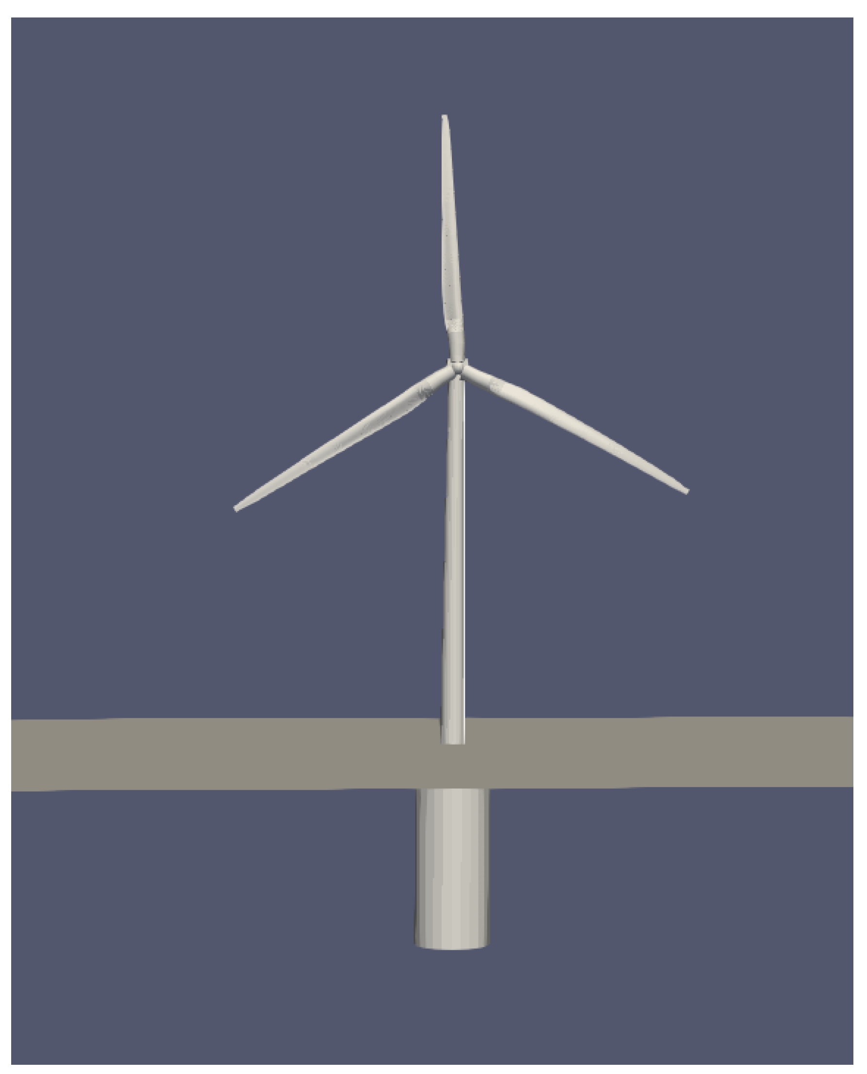
Figure 2.
NREL 5MW wind turbine model in OpenFAST – top view.
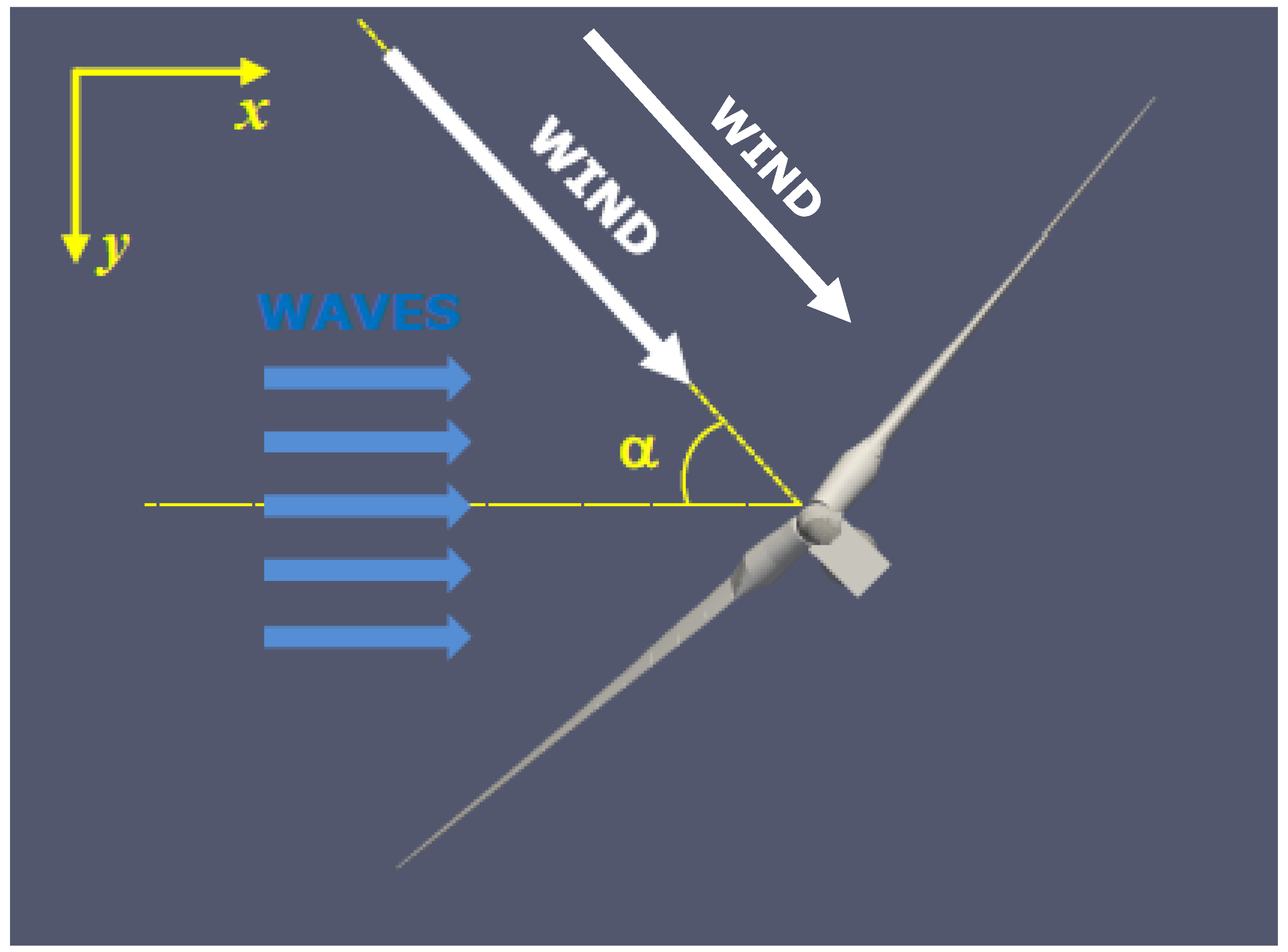
Figure 3.
Wind velocity and rotor thrust as a function of time for different wind alignments: (a) 0°, (b) 45°, (c) 90°.
Figure 3.
Wind velocity and rotor thrust as a function of time for different wind alignments: (a) 0°, (b) 45°, (c) 90°.
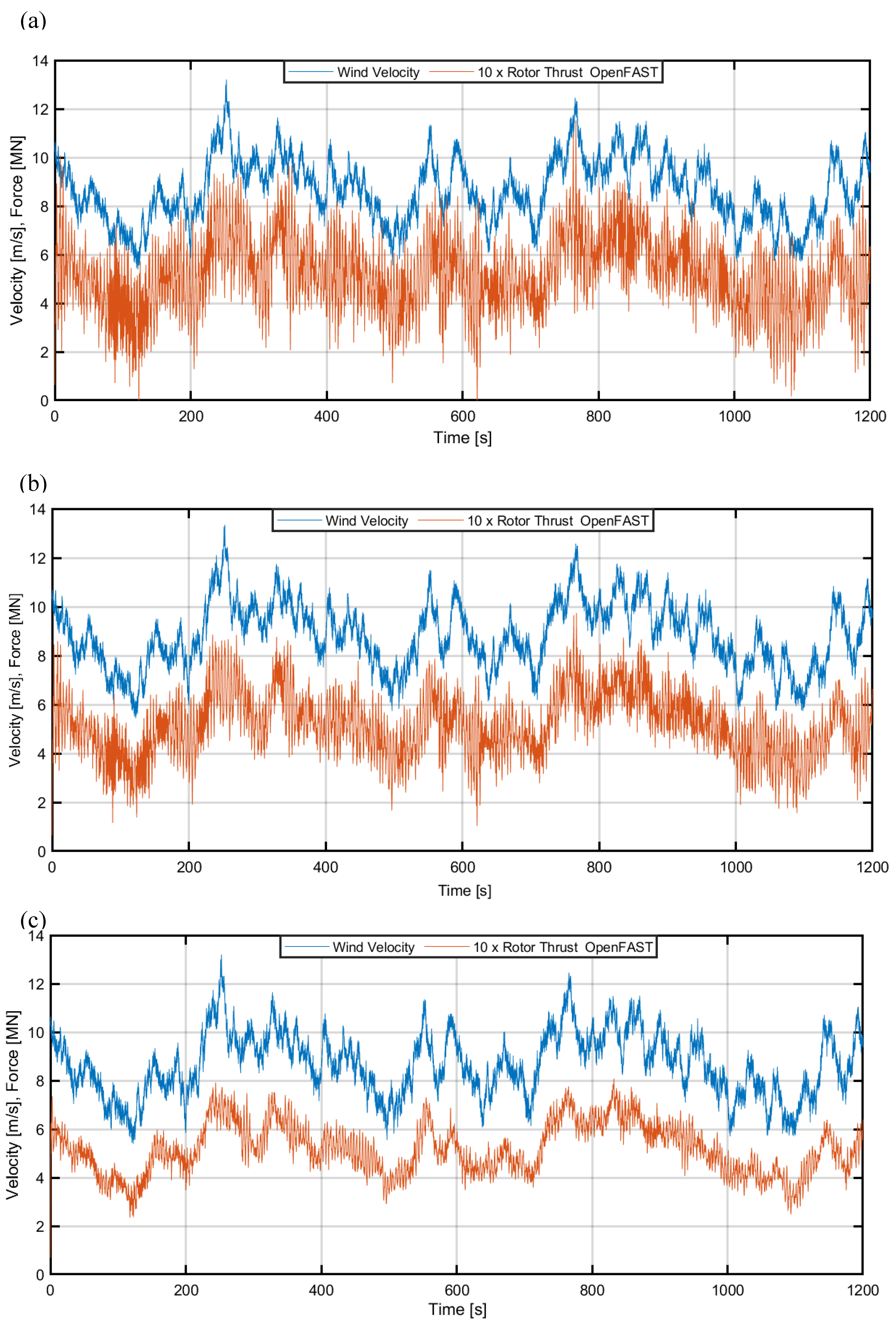
Figure 4.
TLP surge and TLP sway as a function of time for different wind alignments: (a) 0°, (b) 45°, (c) 90°.
Figure 4.
TLP surge and TLP sway as a function of time for different wind alignments: (a) 0°, (b) 45°, (c) 90°.
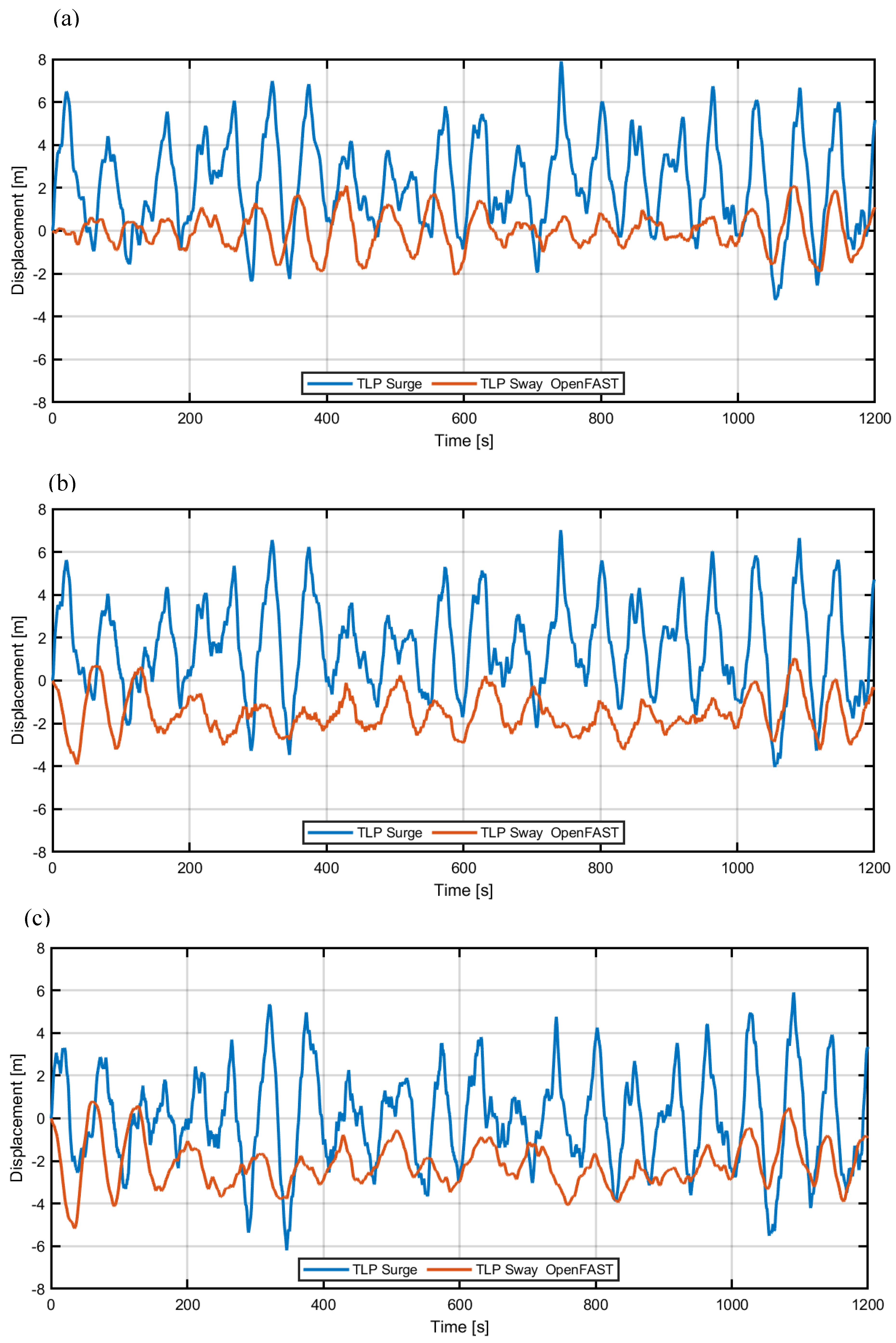
Figure 5.
Tower tip displacement (along the waves / transversal) as a function of time for different wind alignments: (a) 0°, (b) 45°, (c) 90°.
Figure 5.
Tower tip displacement (along the waves / transversal) as a function of time for different wind alignments: (a) 0°, (b) 45°, (c) 90°.
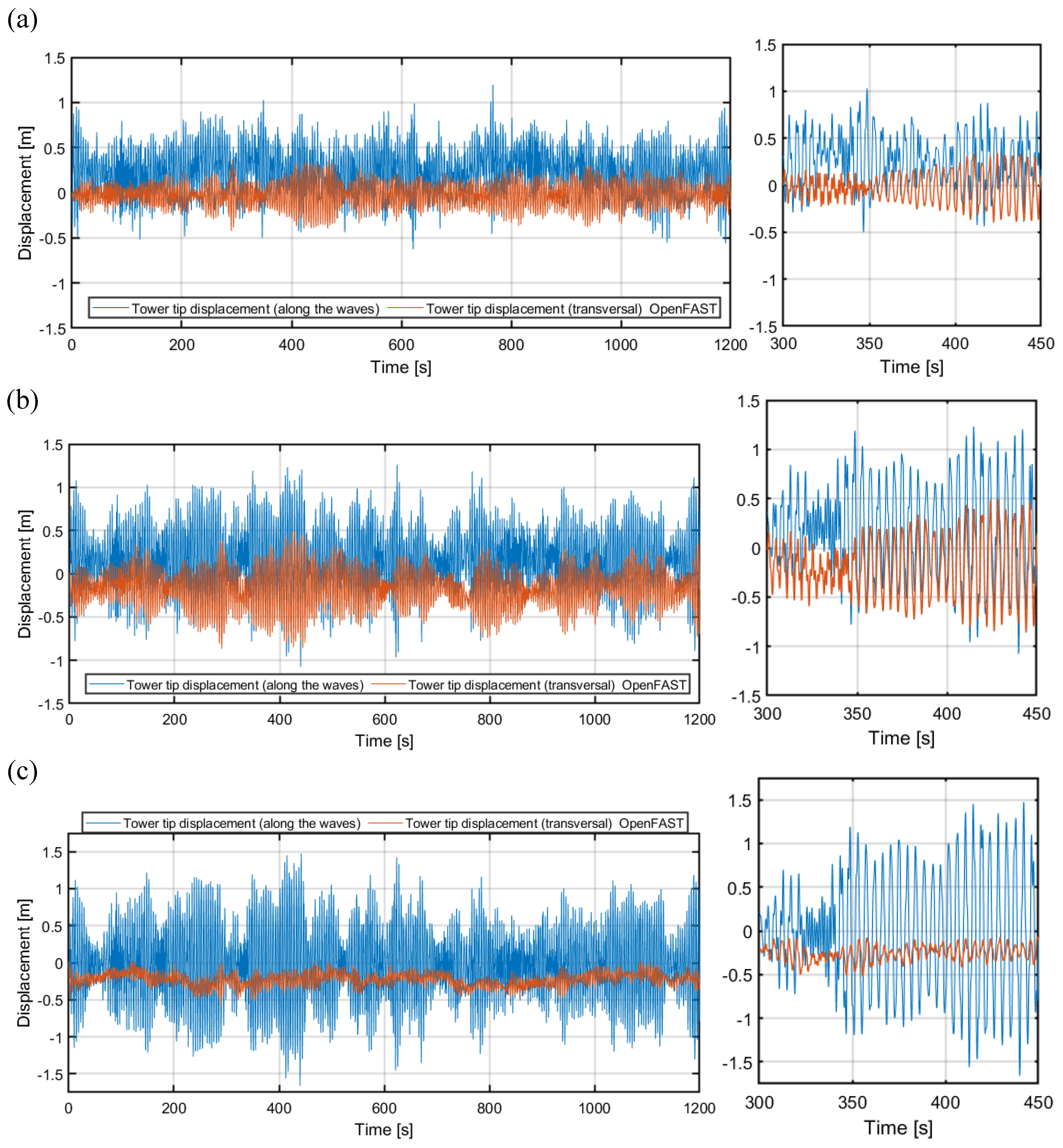
Figure 6.
Power spectral density: (a) platform surge, (b) platform sway.
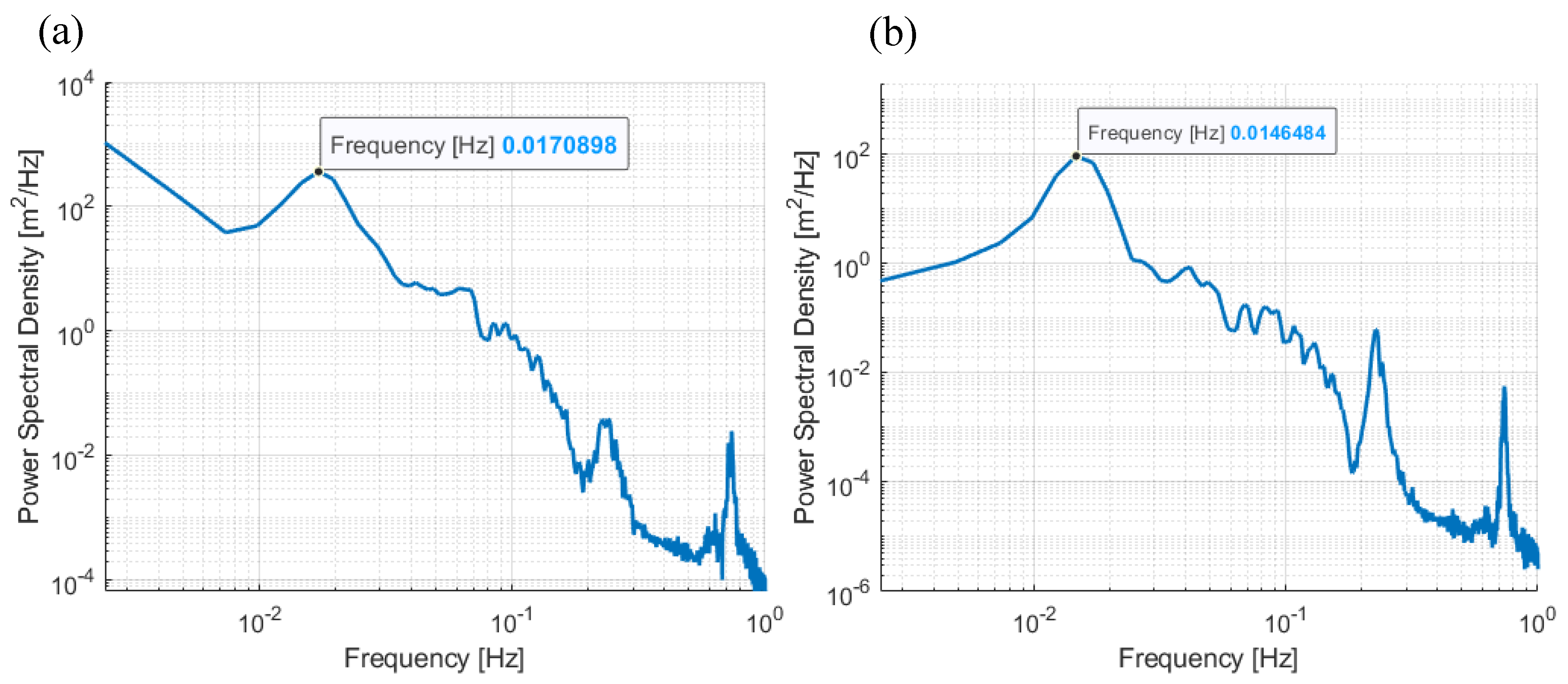
Figure 7.
Tower-nacelle-TLP mode shapes from Comsol Multiphysics: (a) 1st along the waves at 3.2813 rd/s, (b) 1st transversal at 3.2813 rd/s, (c) 2nd along the waves at 18.775 rd/s, (d) 2nd transversal at 18.775 rd/s.
Figure 7.
Tower-nacelle-TLP mode shapes from Comsol Multiphysics: (a) 1st along the waves at 3.2813 rd/s, (b) 1st transversal at 3.2813 rd/s, (c) 2nd along the waves at 18.775 rd/s, (d) 2nd transversal at 18.775 rd/s.
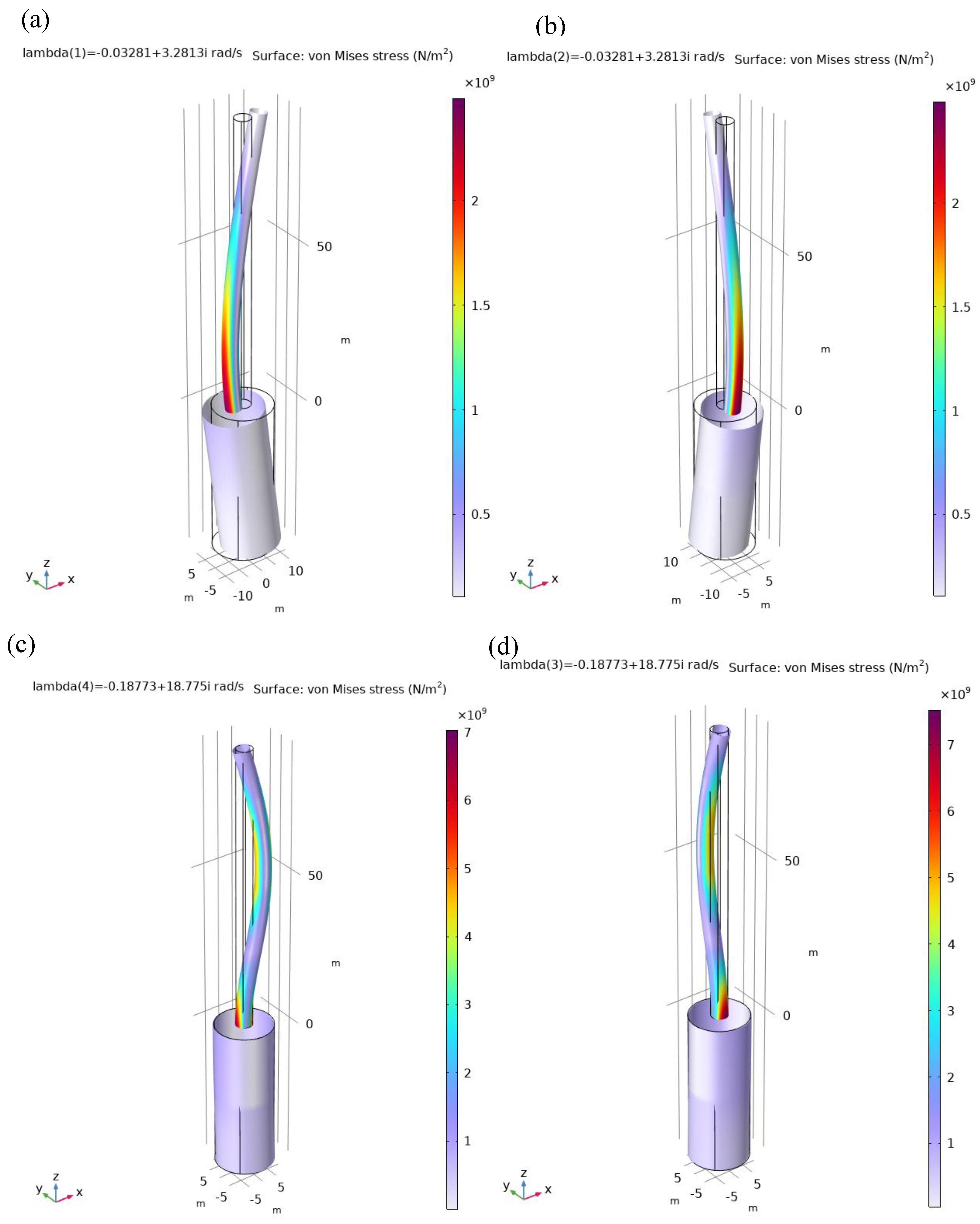
Figure 8.
The regarded model diagram along x-direction (y-direction similarity), including tower-nacelle model with two tower bending modes for each direction exported from Comsol Multiphysics and fundamental platform surge (sway) mode.
Figure 8.
The regarded model diagram along x-direction (y-direction similarity), including tower-nacelle model with two tower bending modes for each direction exported from Comsol Multiphysics and fundamental platform surge (sway) mode.
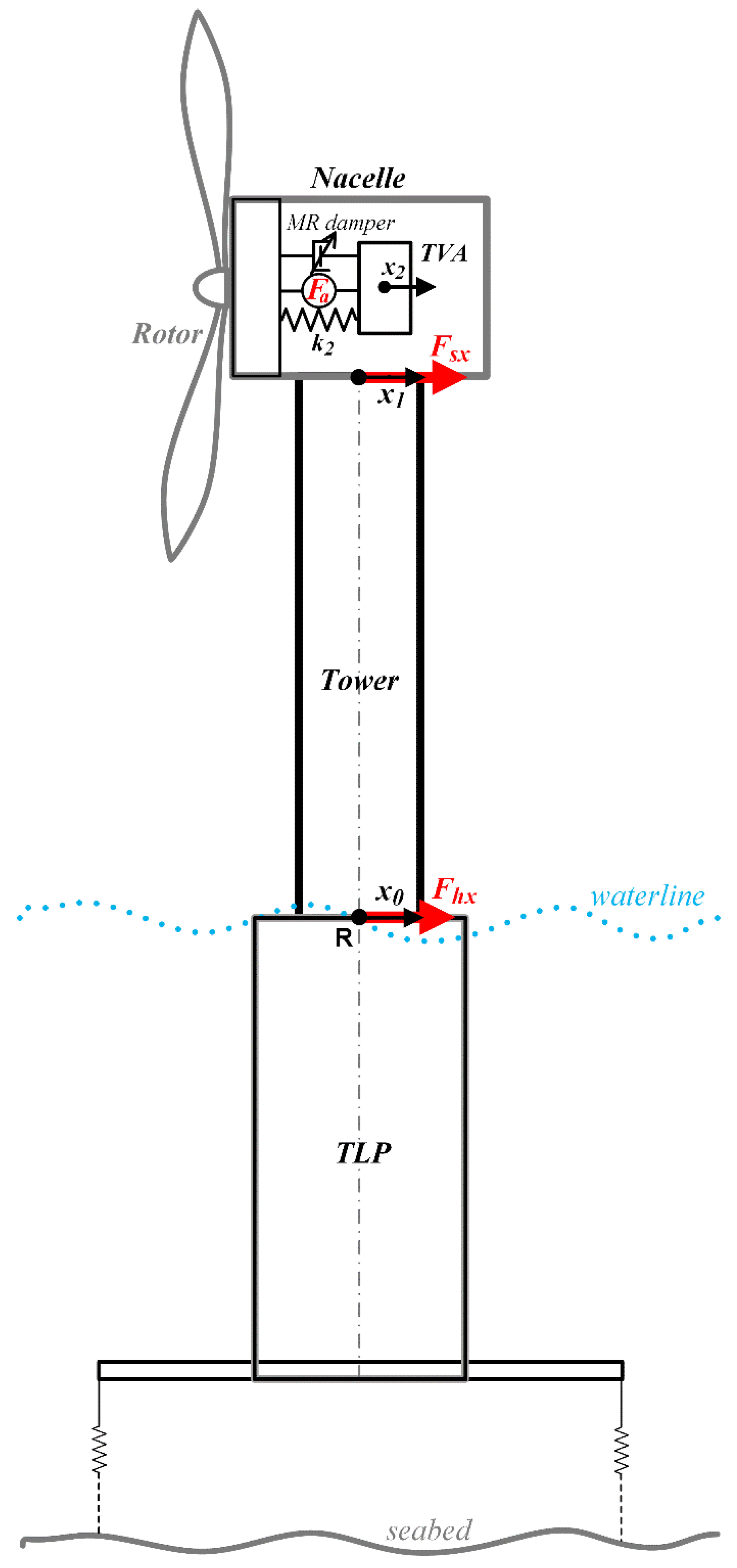
Figure 9.
TLP surge and TLP sway as a function of time for different wind alignments without the TVA: (a) 0°, (b) 45°, (c) 90°.
Figure 9.
TLP surge and TLP sway as a function of time for different wind alignments without the TVA: (a) 0°, (b) 45°, (c) 90°.
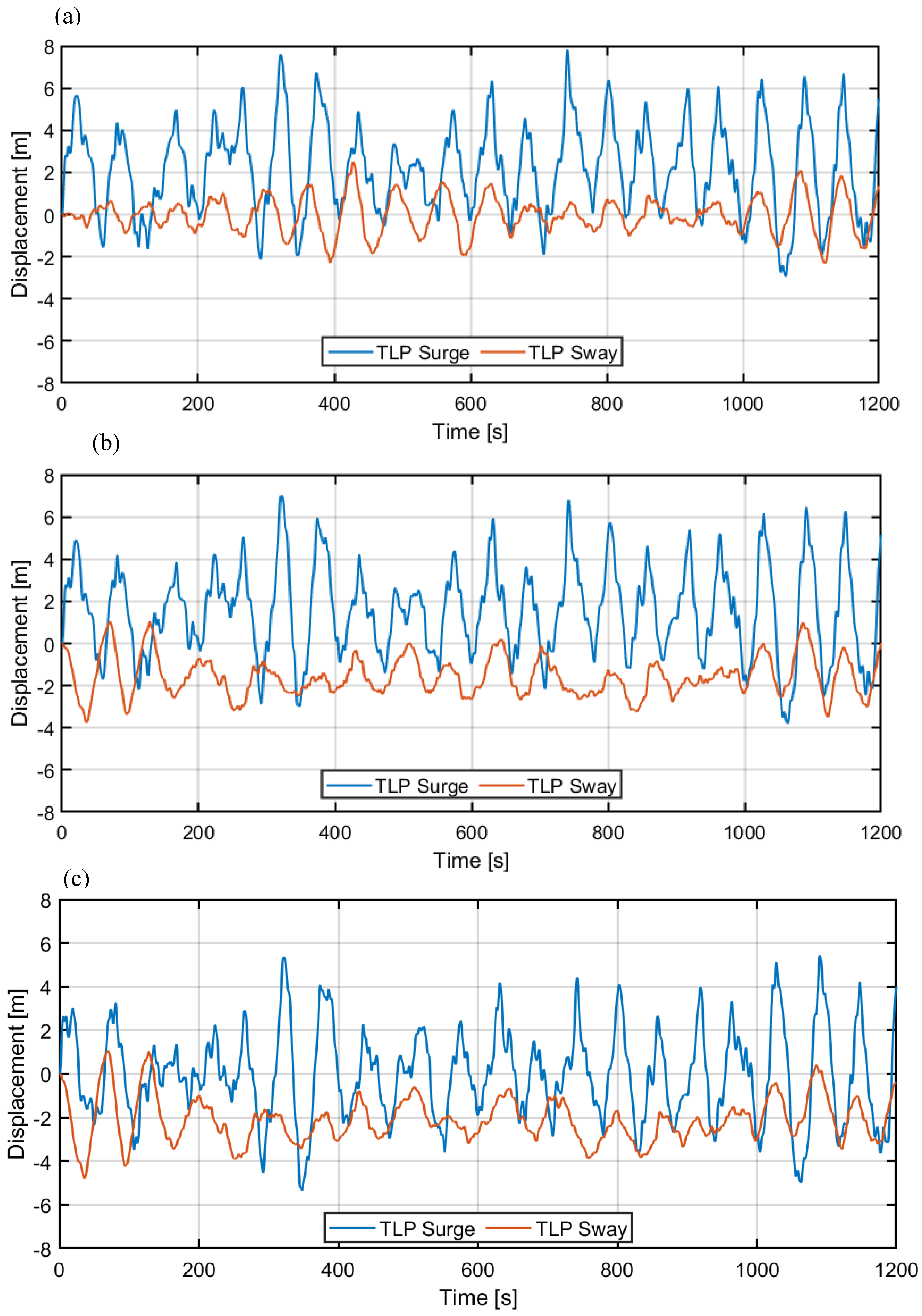
Figure 10.
Tower tip displacement (along the waves / transversal) as a function of time for different wind alignments without the TVA: (a) 0°, (b) 45°, (c) 90°.
Figure 10.
Tower tip displacement (along the waves / transversal) as a function of time for different wind alignments without the TVA: (a) 0°, (b) 45°, (c) 90°.
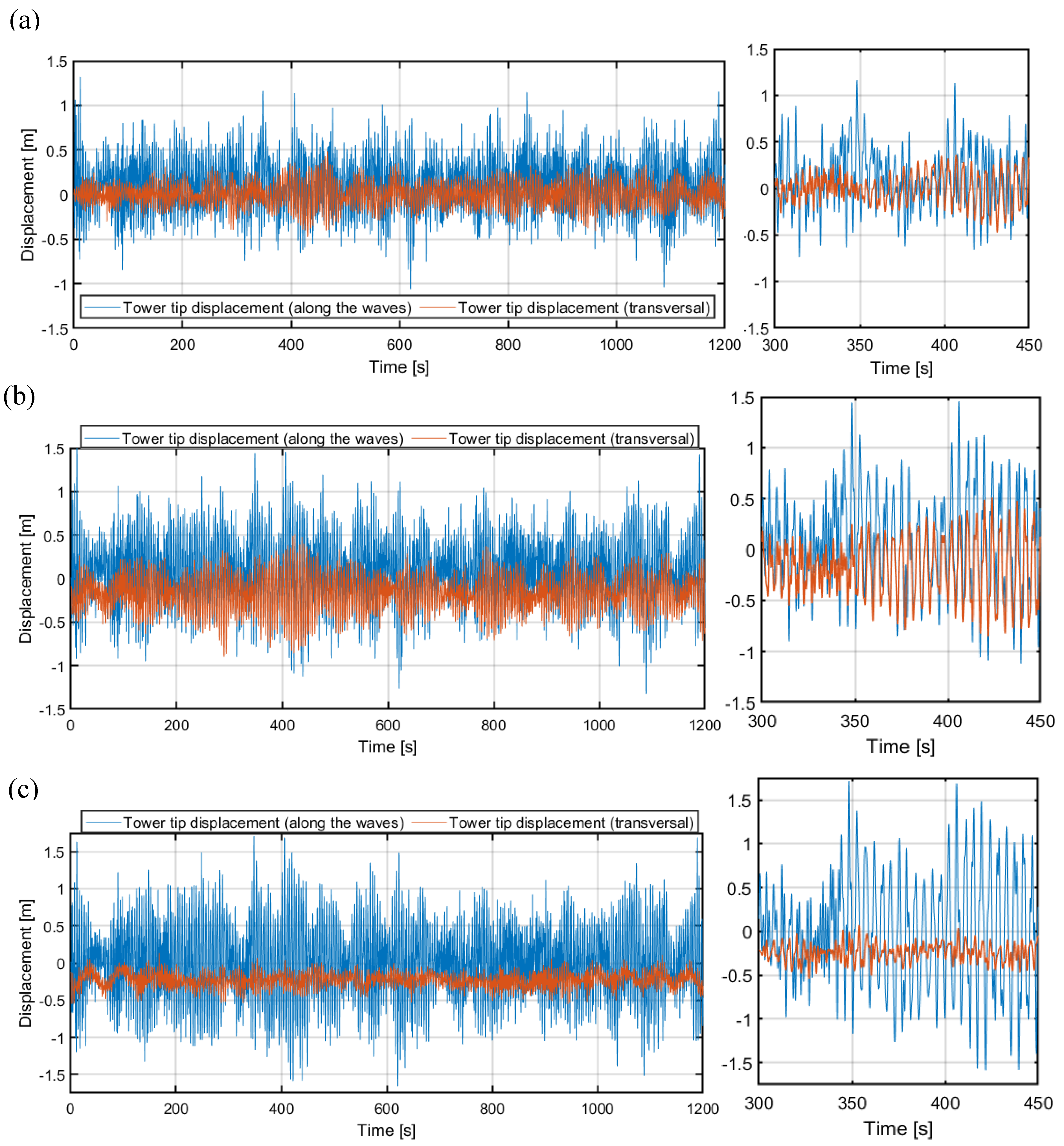
Figure 11.
Tower tip displacement (along the waves / transversal) as a function of time for different wind-wave alignments with 20 ton passive TVA: (a) 0°, (b) 45°, (c) 90°.
Figure 11.
Tower tip displacement (along the waves / transversal) as a function of time for different wind-wave alignments with 20 ton passive TVA: (a) 0°, (b) 45°, (c) 90°.
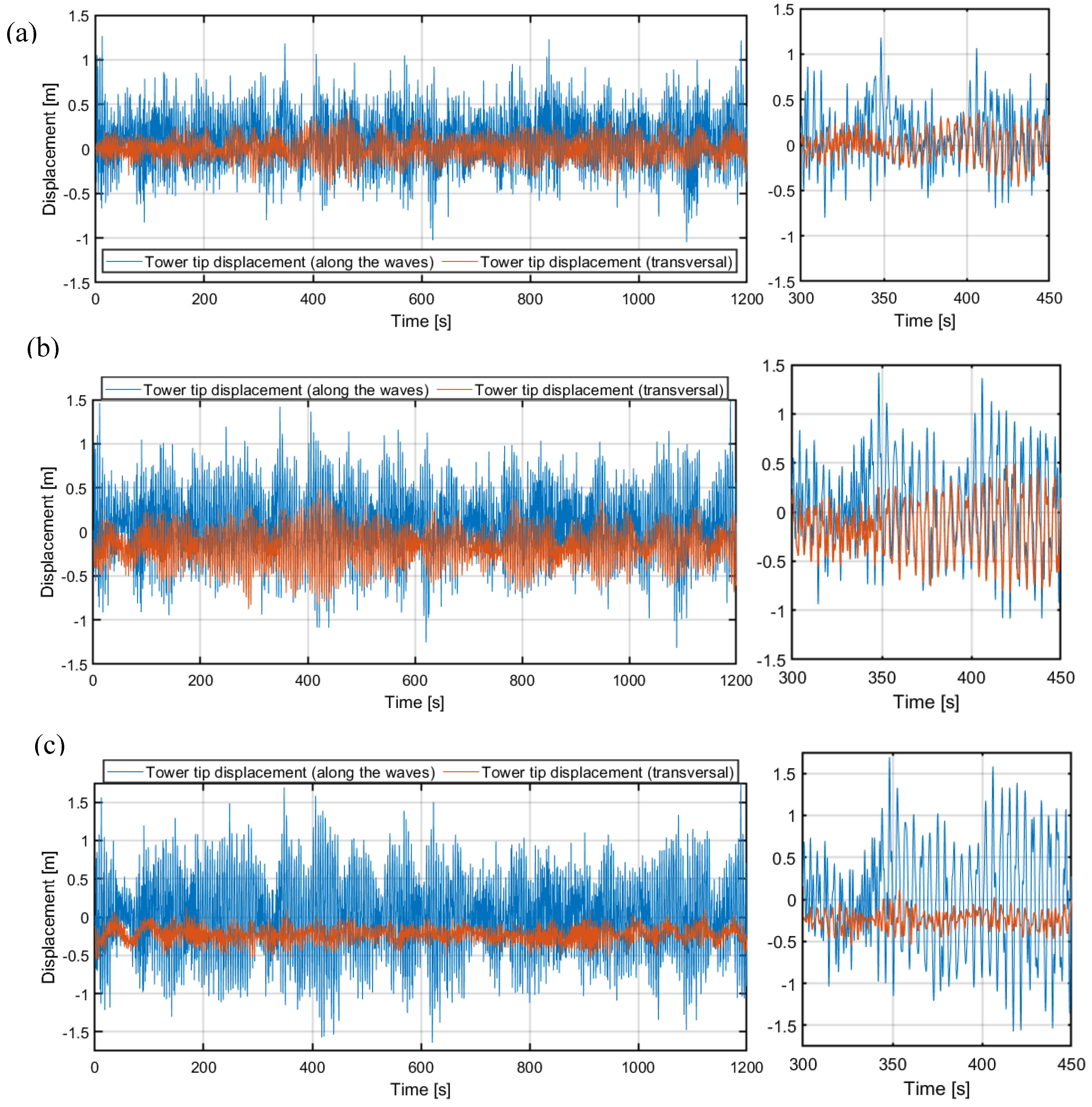
Figure 12.
Tower tip displacement (along the waves / transversal) as a function of time for different wind-wave alignments with 10 ton semi-active MR-TVA: (a) 0°, (b) 45°, (c) 90°.
Figure 12.
Tower tip displacement (along the waves / transversal) as a function of time for different wind-wave alignments with 10 ton semi-active MR-TVA: (a) 0°, (b) 45°, (c) 90°.
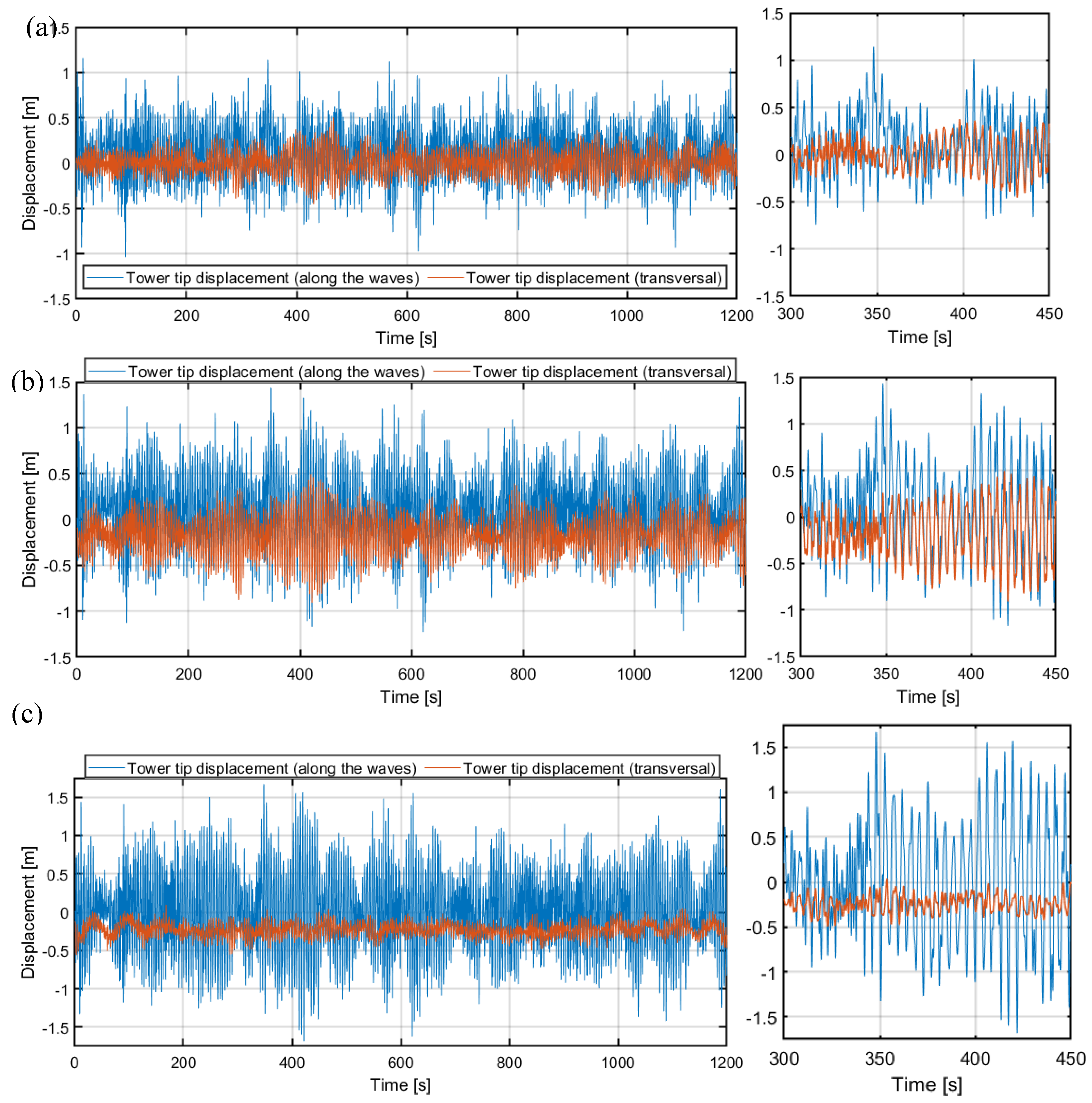
Figure 13.
Tower tip displacement (along the waves / transversal) as a function of time for different wind-wave alignments with 10 ton hybrid H-MR-TVA v2: (a) 0°, (b) 45°, (c) 90°.
Figure 13.
Tower tip displacement (along the waves / transversal) as a function of time for different wind-wave alignments with 10 ton hybrid H-MR-TVA v2: (a) 0°, (b) 45°, (c) 90°.
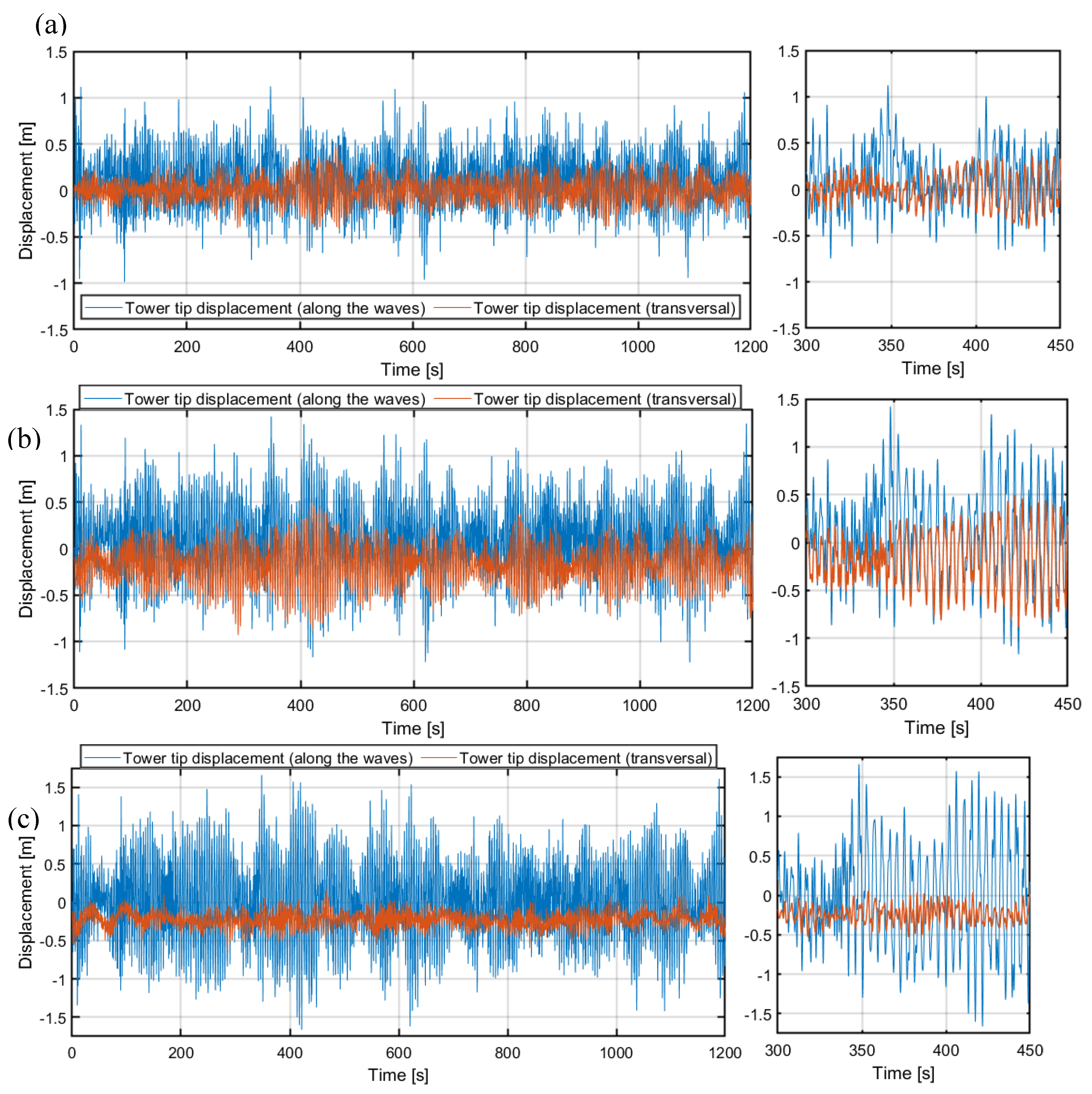
Figure 14.
PSD of tower tip displacement along the waves x1–x0 for different TVA configurations and wind alignments: (a) 0°, (b) 90°.
Figure 14.
PSD of tower tip displacement along the waves x1–x0 for different TVA configurations and wind alignments: (a) 0°, (b) 90°.
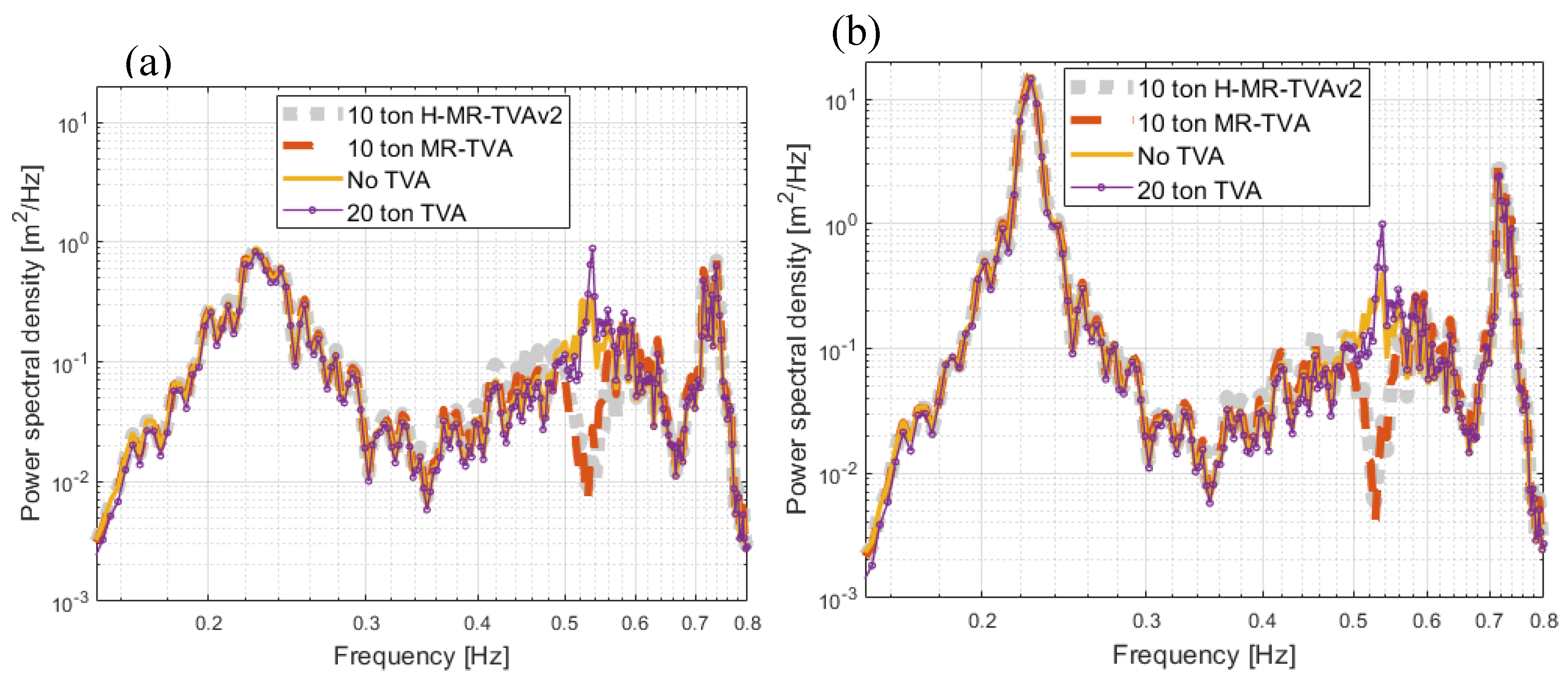
Table 3.
20 ton OpenFAST passive TVA parameters.
| TVA mass (for each axis X and Y) | 20 t |
| Spring stiffness | 28.0 kN/m |
| Damping coefficient | 2.8 kNs/m |
| Displacement limit | 10 m |
| Stop-bumper additional stiffness | 15.0 kN/m |
| Stop-bumper additional damping coeff. | 10.0 kNs/m |
| Installation height | 90 m |
Table 4.
Comsol Multiphysics – MATAB/Simulink vs. OpenFAST model verification.
|
Models α |
OpenFAST | Comsol Multiphysics –MATAB/Simulink | |||||
| Index | 0ᵒ | 45ᵒ | 90ᵒ | 0ᵒ | 45ᵒ | 90ᵒ | |
| Along the waves (x) | [m] | 3.0442 | 2.6302 | 2.2095 | 3.0546 | 2.6341 | 2.2393 |
| [m] | 7.9061 | 7.0154 | 6.1960 | 7.8123 | 6.9996 | 5.7403 | |
| [m] | 0.3429 | 0.3931 | 0.5028 | 0.3095 | 0.3921 | 0.5060 | |
| [m] | 1.1976 | 1.2608 | 1.6612 | 1.3190 | 1.5271 | 1.7135 | |
| Transversal (y) | [m] | 0.8452 | 1.8037 | 2.4395 | 0.8606 | 1.8328 | 2.4515 |
| [m] | 2.1009 | 3.9087 | 5.1601 | 2.5073 | 3.7537 | 5.0019 | |
| [m] | 0.1322 | 0.2785 | 0.2462 | 0.1344 | 0.2747 | 0.2494 | |
| [m] | 0.4206 | 0.8675 | 0.5812 | 0.4822 | 0.8986 | 0.5550 | |
Table 5.
10 ton passive TVA / (H-)MR-TVA parameters.
| m2 | 10.0 t |
| k2 | 102.7 kN/m |
| c2 | 5.886 kNs/m |
| Fmrnom | 100 kN (160 kN peak force) |
| Fanom1 | 7.1 kN (H-MR-TVAv1) |
| Fanom2 | 14.2 kN (H-MR-TVAv2) |
Table 6.
Synthetic results for 0° wind-wave alignment.
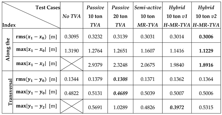
Table 7.
Synthetic results for 45° wind-wave alignment.
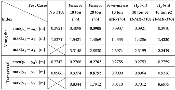
Table 8.
Synthetic results for 90° wind-wave alignment.
Disclaimer/Publisher’s Note: The statements, opinions and data contained in all publications are solely those of the individual author(s) and contributor(s) and not of MDPI and/or the editor(s). MDPI and/or the editor(s) disclaim responsibility for any injury to people or property resulting from any ideas, methods, instructions or products referred to in the content. |
© 2025 by the authors. Licensee MDPI, Basel, Switzerland. This article is an open access article distributed under the terms and conditions of the Creative Commons Attribution (CC BY) license (http://creativecommons.org/licenses/by/4.0/).
Copyright: This open access article is published under a Creative Commons CC BY 4.0 license, which permit the free download, distribution, and reuse, provided that the author and preprint are cited in any reuse.


